WO2022064939A1 - Carbon nanotube aqueous dispersion, conductive film, electrode, and solar cell and method for producing same - Google Patents
Carbon nanotube aqueous dispersion, conductive film, electrode, and solar cell and method for producing same Download PDFInfo
- Publication number
- WO2022064939A1 WO2022064939A1 PCT/JP2021/031242 JP2021031242W WO2022064939A1 WO 2022064939 A1 WO2022064939 A1 WO 2022064939A1 JP 2021031242 W JP2021031242 W JP 2021031242W WO 2022064939 A1 WO2022064939 A1 WO 2022064939A1
- Authority
- WO
- WIPO (PCT)
- Prior art keywords
- solar cell
- electrode
- conductive film
- cnt
- aqueous dispersion
- Prior art date
Links
- 239000006185 dispersion Substances 0.000 title claims abstract description 97
- OKTJSMMVPCPJKN-UHFFFAOYSA-N Carbon Chemical compound [C] OKTJSMMVPCPJKN-UHFFFAOYSA-N 0.000 title claims abstract description 96
- 239000002041 carbon nanotube Substances 0.000 title claims abstract description 59
- 229910021393 carbon nanotube Inorganic materials 0.000 title claims abstract description 41
- 238000004519 manufacturing process Methods 0.000 title claims description 31
- XLYOFNOQVPJJNP-UHFFFAOYSA-N water Substances O XLYOFNOQVPJJNP-UHFFFAOYSA-N 0.000 claims abstract description 48
- 239000006230 acetylene black Substances 0.000 claims abstract description 45
- 239000002270 dispersing agent Substances 0.000 claims abstract description 35
- 239000002109 single walled nanotube Substances 0.000 claims abstract description 24
- 238000000034 method Methods 0.000 claims description 52
- 239000002904 solvent Substances 0.000 claims description 39
- WEVYAHXRMPXWCK-UHFFFAOYSA-N Acetonitrile Chemical compound CC#N WEVYAHXRMPXWCK-UHFFFAOYSA-N 0.000 claims description 36
- 239000002562 thickening agent Substances 0.000 claims description 33
- PPBRXRYQALVLMV-UHFFFAOYSA-N Styrene Chemical compound C=CC1=CC=CC=C1 PPBRXRYQALVLMV-UHFFFAOYSA-N 0.000 claims description 22
- 239000008151 electrolyte solution Substances 0.000 claims description 22
- 238000001035 drying Methods 0.000 claims description 20
- 239000000126 substance Substances 0.000 claims description 20
- 239000000758 substrate Substances 0.000 claims description 18
- YEJRWHAVMIAJKC-UHFFFAOYSA-N 4-Butyrolactone Chemical compound O=C1CCCO1 YEJRWHAVMIAJKC-UHFFFAOYSA-N 0.000 claims description 16
- 239000003792 electrolyte Substances 0.000 claims description 15
- 239000007788 liquid Substances 0.000 claims description 15
- 229920002818 (Hydroxyethyl)methacrylate Polymers 0.000 claims description 11
- WOBHKFSMXKNTIM-UHFFFAOYSA-N Hydroxyethyl methacrylate Chemical compound CC(=C)C(=O)OCCO WOBHKFSMXKNTIM-UHFFFAOYSA-N 0.000 claims description 11
- 229920001577 copolymer Polymers 0.000 claims description 11
- 229920000642 polymer Polymers 0.000 claims description 9
- JLGLQAWTXXGVEM-UHFFFAOYSA-N triethylene glycol monomethyl ether Chemical compound COCCOCCOCCO JLGLQAWTXXGVEM-UHFFFAOYSA-N 0.000 claims description 8
- OOWFYDWAMOKVSF-UHFFFAOYSA-N 3-methoxypropanenitrile Chemical compound COCCC#N OOWFYDWAMOKVSF-UHFFFAOYSA-N 0.000 claims description 7
- 229910052799 carbon Inorganic materials 0.000 claims description 7
- 239000002071 nanotube Substances 0.000 claims 1
- 239000010408 film Substances 0.000 description 118
- 239000010410 layer Substances 0.000 description 90
- 238000006243 chemical reaction Methods 0.000 description 49
- 239000003054 catalyst Substances 0.000 description 36
- 230000003197 catalytic effect Effects 0.000 description 33
- 239000000975 dye Substances 0.000 description 24
- -1 polyoxyethylene Polymers 0.000 description 21
- 230000003287 optical effect Effects 0.000 description 20
- 239000004065 semiconductor Substances 0.000 description 19
- 239000010419 fine particle Substances 0.000 description 18
- 230000001235 sensitizing effect Effects 0.000 description 15
- 238000000576 coating method Methods 0.000 description 13
- 239000002356 single layer Substances 0.000 description 13
- 238000002156 mixing Methods 0.000 description 11
- 239000011248 coating agent Substances 0.000 description 10
- 230000001747 exhibiting effect Effects 0.000 description 10
- LFQSCWFLJHTTHZ-UHFFFAOYSA-N Ethanol Chemical compound CCO LFQSCWFLJHTTHZ-UHFFFAOYSA-N 0.000 description 9
- 238000004140 cleaning Methods 0.000 description 9
- 238000011156 evaluation Methods 0.000 description 9
- 229920003171 Poly (ethylene oxide) Polymers 0.000 description 8
- 230000001965 increasing effect Effects 0.000 description 8
- 239000002245 particle Substances 0.000 description 8
- 239000000243 solution Substances 0.000 description 7
- 239000004354 Hydroxyethyl cellulose Substances 0.000 description 6
- 229920000663 Hydroxyethyl cellulose Polymers 0.000 description 6
- WYURNTSHIVDZCO-UHFFFAOYSA-N Tetrahydrofuran Chemical compound C1CCOC1 WYURNTSHIVDZCO-UHFFFAOYSA-N 0.000 description 6
- 239000006229 carbon black Substances 0.000 description 6
- 235000019241 carbon black Nutrition 0.000 description 6
- 235000019447 hydroxyethyl cellulose Nutrition 0.000 description 6
- 150000002500 ions Chemical class 0.000 description 6
- 239000011112 polyethylene naphthalate Substances 0.000 description 6
- IAZDPXIOMUYVGZ-UHFFFAOYSA-N Dimethylsulphoxide Chemical class CS(C)=O IAZDPXIOMUYVGZ-UHFFFAOYSA-N 0.000 description 5
- KFZMGEQAYNKOFK-UHFFFAOYSA-N Isopropanol Chemical compound CC(C)O KFZMGEQAYNKOFK-UHFFFAOYSA-N 0.000 description 5
- ZMXDDKWLCZADIW-UHFFFAOYSA-N N,N-Dimethylformamide Chemical class CN(C)C=O ZMXDDKWLCZADIW-UHFFFAOYSA-N 0.000 description 5
- 230000000052 comparative effect Effects 0.000 description 5
- 229920003207 poly(ethylene-2,6-naphthalate) Polymers 0.000 description 5
- 229920005989 resin Polymers 0.000 description 5
- 239000011347 resin Substances 0.000 description 5
- 238000007650 screen-printing Methods 0.000 description 5
- IJGRMHOSHXDMSA-UHFFFAOYSA-N Atomic nitrogen Chemical compound N#N IJGRMHOSHXDMSA-UHFFFAOYSA-N 0.000 description 4
- 229920002134 Carboxymethyl cellulose Polymers 0.000 description 4
- XTHFKEDIFFGKHM-UHFFFAOYSA-N Dimethoxyethane Chemical compound COCCOC XTHFKEDIFFGKHM-UHFFFAOYSA-N 0.000 description 4
- LYCAIKOWRPUZTN-UHFFFAOYSA-N Ethylene glycol Chemical group OCCO LYCAIKOWRPUZTN-UHFFFAOYSA-N 0.000 description 4
- XEEYBQQBJWHFJM-UHFFFAOYSA-N Iron Chemical compound [Fe] XEEYBQQBJWHFJM-UHFFFAOYSA-N 0.000 description 4
- 238000001237 Raman spectrum Methods 0.000 description 4
- 125000000217 alkyl group Chemical group 0.000 description 4
- 239000012298 atmosphere Substances 0.000 description 4
- 125000004432 carbon atom Chemical group C* 0.000 description 4
- 239000003575 carbonaceous material Substances 0.000 description 4
- 239000001768 carboxy methyl cellulose Substances 0.000 description 4
- 235000010948 carboxy methyl cellulose Nutrition 0.000 description 4
- 239000008112 carboxymethyl-cellulose Substances 0.000 description 4
- 238000005229 chemical vapour deposition Methods 0.000 description 4
- 150000001875 compounds Chemical class 0.000 description 4
- 229920001940 conductive polymer Polymers 0.000 description 4
- GAEKPEKOJKCEMS-UHFFFAOYSA-N gamma-valerolactone Chemical compound CC1CCC(=O)O1 GAEKPEKOJKCEMS-UHFFFAOYSA-N 0.000 description 4
- 239000000463 material Substances 0.000 description 4
- 239000000203 mixture Substances 0.000 description 4
- RUOJZAUFBMNUDX-UHFFFAOYSA-N propylene carbonate Chemical compound CC1COC(=O)O1 RUOJZAUFBMNUDX-UHFFFAOYSA-N 0.000 description 4
- 150000003457 sulfones Chemical class 0.000 description 4
- 238000011282 treatment Methods 0.000 description 4
- 238000005406 washing Methods 0.000 description 4
- RYHBNJHYFVUHQT-UHFFFAOYSA-N 1,4-Dioxane Chemical compound C1COCCO1 RYHBNJHYFVUHQT-UHFFFAOYSA-N 0.000 description 3
- ZWEHNKRNPOVVGH-UHFFFAOYSA-N 2-Butanone Chemical compound CCC(C)=O ZWEHNKRNPOVVGH-UHFFFAOYSA-N 0.000 description 3
- QTBSBXVTEAMEQO-UHFFFAOYSA-N Acetic acid Chemical compound CC(O)=O QTBSBXVTEAMEQO-UHFFFAOYSA-N 0.000 description 3
- CSCPPACGZOOCGX-UHFFFAOYSA-N Acetone Chemical compound CC(C)=O CSCPPACGZOOCGX-UHFFFAOYSA-N 0.000 description 3
- XEKOWRVHYACXOJ-UHFFFAOYSA-N Ethyl acetate Chemical compound CCOC(C)=O XEKOWRVHYACXOJ-UHFFFAOYSA-N 0.000 description 3
- OKKJLVBELUTLKV-UHFFFAOYSA-N Methanol Chemical compound OC OKKJLVBELUTLKV-UHFFFAOYSA-N 0.000 description 3
- MUBZPKHOEPUJKR-UHFFFAOYSA-N Oxalic acid Chemical compound OC(=O)C(O)=O MUBZPKHOEPUJKR-UHFFFAOYSA-N 0.000 description 3
- 239000004372 Polyvinyl alcohol Substances 0.000 description 3
- DNIAPMSPPWPWGF-UHFFFAOYSA-N Propylene glycol Chemical compound CC(O)CO DNIAPMSPPWPWGF-UHFFFAOYSA-N 0.000 description 3
- VYPSYNLAJGMNEJ-UHFFFAOYSA-N Silicium dioxide Chemical compound O=[Si]=O VYPSYNLAJGMNEJ-UHFFFAOYSA-N 0.000 description 3
- GWEVSGVZZGPLCZ-UHFFFAOYSA-N Titan oxide Chemical compound O=[Ti]=O GWEVSGVZZGPLCZ-UHFFFAOYSA-N 0.000 description 3
- ZMANZCXQSJIPKH-UHFFFAOYSA-N Triethylamine Chemical compound CCN(CC)CC ZMANZCXQSJIPKH-UHFFFAOYSA-N 0.000 description 3
- 230000002378 acidificating effect Effects 0.000 description 3
- 230000005540 biological transmission Effects 0.000 description 3
- 239000002717 carbon nanostructure Substances 0.000 description 3
- KRKNYBCHXYNGOX-UHFFFAOYSA-N citric acid Chemical compound OC(=O)CC(O)(C(O)=O)CC(O)=O KRKNYBCHXYNGOX-UHFFFAOYSA-N 0.000 description 3
- 150000005676 cyclic carbonates Chemical class 0.000 description 3
- RTZKZFJDLAIYFH-UHFFFAOYSA-N ether Substances CCOCC RTZKZFJDLAIYFH-UHFFFAOYSA-N 0.000 description 3
- 150000002170 ethers Chemical class 0.000 description 3
- 229910052742 iron Inorganic materials 0.000 description 3
- 239000003273 ketjen black Substances 0.000 description 3
- 238000005259 measurement Methods 0.000 description 3
- 229920002451 polyvinyl alcohol Polymers 0.000 description 3
- 229920000036 polyvinylpyrrolidone Polymers 0.000 description 3
- 239000001267 polyvinylpyrrolidone Substances 0.000 description 3
- 235000013855 polyvinylpyrrolidone Nutrition 0.000 description 3
- 238000002360 preparation method Methods 0.000 description 3
- YLQBMQCUIZJEEH-UHFFFAOYSA-N tetrahydrofuran Natural products C=1C=COC=1 YLQBMQCUIZJEEH-UHFFFAOYSA-N 0.000 description 3
- OGIDPMRJRNCKJF-UHFFFAOYSA-N titanium oxide Inorganic materials [Ti]=O OGIDPMRJRNCKJF-UHFFFAOYSA-N 0.000 description 3
- UINDRJHZBAGQFD-UHFFFAOYSA-O 2-ethyl-3-methyl-1h-imidazol-3-ium Chemical compound CCC1=[NH+]C=CN1C UINDRJHZBAGQFD-UHFFFAOYSA-O 0.000 description 2
- RDKKQZIFDSEMNU-UHFFFAOYSA-N 2-ethylsulfonylpropane Chemical compound CCS(=O)(=O)C(C)C RDKKQZIFDSEMNU-UHFFFAOYSA-N 0.000 description 2
- QKPVEISEHYYHRH-UHFFFAOYSA-N 2-methoxyacetonitrile Chemical compound COCC#N QKPVEISEHYYHRH-UHFFFAOYSA-N 0.000 description 2
- ZCYVEMRRCGMTRW-UHFFFAOYSA-N 7553-56-2 Chemical compound [I] ZCYVEMRRCGMTRW-UHFFFAOYSA-N 0.000 description 2
- XKRFYHLGVUSROY-UHFFFAOYSA-N Argon Chemical compound [Ar] XKRFYHLGVUSROY-UHFFFAOYSA-N 0.000 description 2
- 238000004438 BET method Methods 0.000 description 2
- 229920000089 Cyclic olefin copolymer Polymers 0.000 description 2
- KMTRUDSVKNLOMY-UHFFFAOYSA-N Ethylene carbonate Chemical compound O=C1OCCO1 KMTRUDSVKNLOMY-UHFFFAOYSA-N 0.000 description 2
- VEXZGXHMUGYJMC-UHFFFAOYSA-N Hydrochloric acid Chemical compound Cl VEXZGXHMUGYJMC-UHFFFAOYSA-N 0.000 description 2
- SECXISVLQFMRJM-UHFFFAOYSA-N N-Methylpyrrolidone Chemical compound CN1CCCC1=O SECXISVLQFMRJM-UHFFFAOYSA-N 0.000 description 2
- 241000282320 Panthera leo Species 0.000 description 2
- ISWSIDIOOBJBQZ-UHFFFAOYSA-N Phenol Chemical compound OC1=CC=CC=C1 ISWSIDIOOBJBQZ-UHFFFAOYSA-N 0.000 description 2
- NBIIXXVUZAFLBC-UHFFFAOYSA-N Phosphoric acid Chemical compound OP(O)(O)=O NBIIXXVUZAFLBC-UHFFFAOYSA-N 0.000 description 2
- 229920001609 Poly(3,4-ethylenedioxythiophene) Polymers 0.000 description 2
- 239000004697 Polyetherimide Substances 0.000 description 2
- 239000004642 Polyimide Substances 0.000 description 2
- 239000004734 Polyphenylene sulfide Substances 0.000 description 2
- 238000001069 Raman spectroscopy Methods 0.000 description 2
- AUNGANRZJHBGPY-SCRDCRAPSA-N Riboflavin Chemical compound OC[C@@H](O)[C@@H](O)[C@@H](O)CN1C=2C=C(C)C(C)=CC=2N=C2C1=NC(=O)NC2=O AUNGANRZJHBGPY-SCRDCRAPSA-N 0.000 description 2
- QAOWNCQODCNURD-UHFFFAOYSA-N Sulfuric acid Chemical compound OS(O)(=O)=O QAOWNCQODCNURD-UHFFFAOYSA-N 0.000 description 2
- 229920010524 Syndiotactic polystyrene Polymers 0.000 description 2
- XLOMVQKBTHCTTD-UHFFFAOYSA-N Zinc monoxide Chemical compound [Zn]=O XLOMVQKBTHCTTD-UHFFFAOYSA-N 0.000 description 2
- 239000002253 acid Substances 0.000 description 2
- 125000001931 aliphatic group Chemical group 0.000 description 2
- 150000005215 alkyl ethers Chemical group 0.000 description 2
- 239000011230 binding agent Substances 0.000 description 2
- GDTBXPJZTBHREO-UHFFFAOYSA-N bromine Substances BrBr GDTBXPJZTBHREO-UHFFFAOYSA-N 0.000 description 2
- 229910052794 bromium Inorganic materials 0.000 description 2
- 239000000460 chlorine Substances 0.000 description 2
- 229910052801 chlorine Inorganic materials 0.000 description 2
- 229910001429 cobalt ion Inorganic materials 0.000 description 2
- 239000000470 constituent Substances 0.000 description 2
- 238000001816 cooling Methods 0.000 description 2
- 229910001431 copper ion Inorganic materials 0.000 description 2
- ZYGHJZDHTFUPRJ-UHFFFAOYSA-N coumarin Chemical compound C1=CC=C2OC(=O)C=CC2=C1 ZYGHJZDHTFUPRJ-UHFFFAOYSA-N 0.000 description 2
- JHIVVAPYMSGYDF-UHFFFAOYSA-N cyclohexanone Chemical compound O=C1CCCCC1 JHIVVAPYMSGYDF-UHFFFAOYSA-N 0.000 description 2
- 238000003795 desorption Methods 0.000 description 2
- SWXVUIWOUIDPGS-UHFFFAOYSA-N diacetone alcohol Chemical compound CC(=O)CC(C)(C)O SWXVUIWOUIDPGS-UHFFFAOYSA-N 0.000 description 2
- 238000007598 dipping method Methods 0.000 description 2
- 150000002148 esters Chemical class 0.000 description 2
- 229910052740 iodine Inorganic materials 0.000 description 2
- 239000011630 iodine Substances 0.000 description 2
- 229920000831 ionic polymer Polymers 0.000 description 2
- HSZCZNFXUDYRKD-UHFFFAOYSA-M lithium iodide Chemical compound [Li+].[I-] HSZCZNFXUDYRKD-UHFFFAOYSA-M 0.000 description 2
- 229910044991 metal oxide Inorganic materials 0.000 description 2
- 150000004706 metal oxides Chemical class 0.000 description 2
- BDAGIHXWWSANSR-UHFFFAOYSA-N methanoic acid Natural products OC=O BDAGIHXWWSANSR-UHFFFAOYSA-N 0.000 description 2
- 150000002825 nitriles Chemical class 0.000 description 2
- 229910052757 nitrogen Inorganic materials 0.000 description 2
- 229920002492 poly(sulfone) Polymers 0.000 description 2
- 229920001230 polyarylate Polymers 0.000 description 2
- 229920001601 polyetherimide Polymers 0.000 description 2
- 229920000139 polyethylene terephthalate Polymers 0.000 description 2
- 239000005020 polyethylene terephthalate Substances 0.000 description 2
- 229920001721 polyimide Polymers 0.000 description 2
- 229920000069 polyphenylene sulfide Polymers 0.000 description 2
- 239000011164 primary particle Substances 0.000 description 2
- 239000000565 sealant Substances 0.000 description 2
- 239000002002 slurry Substances 0.000 description 2
- 238000005507 spraying Methods 0.000 description 2
- 239000003115 supporting electrolyte Substances 0.000 description 2
- 238000010345 tape casting Methods 0.000 description 2
- 239000010409 thin film Substances 0.000 description 2
- VXUYXOFXAQZZMF-UHFFFAOYSA-N titanium(IV) isopropoxide Chemical compound CC(C)O[Ti](OC(C)C)(OC(C)C)OC(C)C VXUYXOFXAQZZMF-UHFFFAOYSA-N 0.000 description 2
- 229910052724 xenon Inorganic materials 0.000 description 2
- FHNFHKCVQCLJFQ-UHFFFAOYSA-N xenon atom Chemical compound [Xe] FHNFHKCVQCLJFQ-UHFFFAOYSA-N 0.000 description 2
- QGKMIGUHVLGJBR-UHFFFAOYSA-M (4z)-1-(3-methylbutyl)-4-[[1-(3-methylbutyl)quinolin-1-ium-4-yl]methylidene]quinoline;iodide Chemical compound [I-].C12=CC=CC=C2N(CCC(C)C)C=CC1=CC1=CC=[N+](CCC(C)C)C2=CC=CC=C12 QGKMIGUHVLGJBR-UHFFFAOYSA-M 0.000 description 1
- ISHFYECQSXFODS-UHFFFAOYSA-M 1,2-dimethyl-3-propylimidazol-1-ium;iodide Chemical compound [I-].CCCN1C=C[N+](C)=C1C ISHFYECQSXFODS-UHFFFAOYSA-M 0.000 description 1
- SXYRTDICSOVQNZ-UHFFFAOYSA-N 1-(2-methoxyethoxy)ethanol Chemical compound COCCOC(C)O SXYRTDICSOVQNZ-UHFFFAOYSA-N 0.000 description 1
- XNWFRZJHXBZDAG-UHFFFAOYSA-N 2-METHOXYETHANOL Chemical compound COCCO XNWFRZJHXBZDAG-UHFFFAOYSA-N 0.000 description 1
- POAOYUHQDCAZBD-UHFFFAOYSA-N 2-butoxyethanol Chemical compound CCCCOCCO POAOYUHQDCAZBD-UHFFFAOYSA-N 0.000 description 1
- LLYXJBROWQDVMI-UHFFFAOYSA-N 2-chloro-4-nitrotoluene Chemical compound CC1=CC=C([N+]([O-])=O)C=C1Cl LLYXJBROWQDVMI-UHFFFAOYSA-N 0.000 description 1
- ZNQVEEAIQZEUHB-UHFFFAOYSA-N 2-ethoxyethanol Chemical compound CCOCCO ZNQVEEAIQZEUHB-UHFFFAOYSA-N 0.000 description 1
- UUIMDJFBHNDZOW-UHFFFAOYSA-N 2-tert-butylpyridine Chemical compound CC(C)(C)C1=CC=CC=N1 UUIMDJFBHNDZOW-UHFFFAOYSA-N 0.000 description 1
- OSWFIVFLDKOXQC-UHFFFAOYSA-N 4-(3-methoxyphenyl)aniline Chemical compound COC1=CC=CC(C=2C=CC(N)=CC=2)=C1 OSWFIVFLDKOXQC-UHFFFAOYSA-N 0.000 description 1
- WKBOTKDWSSQWDR-UHFFFAOYSA-N Bromine atom Chemical compound [Br] WKBOTKDWSSQWDR-UHFFFAOYSA-N 0.000 description 1
- ZAMOUSCENKQFHK-UHFFFAOYSA-N Chlorine atom Chemical compound [Cl] ZAMOUSCENKQFHK-UHFFFAOYSA-N 0.000 description 1
- RYGMFSIKBFXOCR-UHFFFAOYSA-N Copper Chemical compound [Cu] RYGMFSIKBFXOCR-UHFFFAOYSA-N 0.000 description 1
- JPVYNHNXODAKFH-UHFFFAOYSA-N Cu2+ Chemical compound [Cu+2] JPVYNHNXODAKFH-UHFFFAOYSA-N 0.000 description 1
- AUNGANRZJHBGPY-UHFFFAOYSA-N D-Lyxoflavin Natural products OCC(O)C(O)C(O)CN1C=2C=C(C)C(C)=CC=2N=C2C1=NC(=O)NC2=O AUNGANRZJHBGPY-UHFFFAOYSA-N 0.000 description 1
- FEWJPZIEWOKRBE-JCYAYHJZSA-N Dextrotartaric acid Chemical compound OC(=O)[C@H](O)[C@@H](O)C(O)=O FEWJPZIEWOKRBE-JCYAYHJZSA-N 0.000 description 1
- RAXXELZNTBOGNW-UHFFFAOYSA-O Imidazolium Chemical compound C1=C[NH+]=CN1 RAXXELZNTBOGNW-UHFFFAOYSA-O 0.000 description 1
- HBBGRARXTFLTSG-UHFFFAOYSA-N Lithium ion Chemical compound [Li+] HBBGRARXTFLTSG-UHFFFAOYSA-N 0.000 description 1
- CERQOIWHTDAKMF-UHFFFAOYSA-M Methacrylate Chemical compound CC(=C)C([O-])=O CERQOIWHTDAKMF-UHFFFAOYSA-M 0.000 description 1
- NTIZESTWPVYFNL-UHFFFAOYSA-N Methyl isobutyl ketone Chemical compound CC(C)CC(C)=O NTIZESTWPVYFNL-UHFFFAOYSA-N 0.000 description 1
- UIHCLUNTQKBZGK-UHFFFAOYSA-N Methyl isobutyl ketone Natural products CCC(C)C(C)=O UIHCLUNTQKBZGK-UHFFFAOYSA-N 0.000 description 1
- GRYLNZFGIOXLOG-UHFFFAOYSA-N Nitric acid Chemical compound O[N+]([O-])=O GRYLNZFGIOXLOG-UHFFFAOYSA-N 0.000 description 1
- 239000002033 PVDF binder Substances 0.000 description 1
- 229920012266 Poly(ether sulfone) PES Polymers 0.000 description 1
- 239000002202 Polyethylene glycol Substances 0.000 description 1
- 239000004793 Polystyrene Substances 0.000 description 1
- XBDQKXXYIPTUBI-UHFFFAOYSA-M Propionate Chemical compound CCC([O-])=O XBDQKXXYIPTUBI-UHFFFAOYSA-M 0.000 description 1
- KJTLSVCANCCWHF-UHFFFAOYSA-N Ruthenium Chemical compound [Ru] KJTLSVCANCCWHF-UHFFFAOYSA-N 0.000 description 1
- 239000012327 Ruthenium complex Substances 0.000 description 1
- ITBPIKUGMIZTJR-UHFFFAOYSA-N [bis(hydroxymethyl)amino]methanol Chemical compound OCN(CO)CO ITBPIKUGMIZTJR-UHFFFAOYSA-N 0.000 description 1
- KXKVLQRXCPHEJC-UHFFFAOYSA-N acetic acid trimethyl ester Natural products COC(C)=O KXKVLQRXCPHEJC-UHFFFAOYSA-N 0.000 description 1
- 150000007513 acids Chemical class 0.000 description 1
- 239000012190 activator Substances 0.000 description 1
- 238000007605 air drying Methods 0.000 description 1
- 238000007754 air knife coating Methods 0.000 description 1
- 150000001298 alcohols Chemical class 0.000 description 1
- 125000005037 alkyl phenyl group Chemical group 0.000 description 1
- HSFWRNGVRCDJHI-UHFFFAOYSA-N alpha-acetylene Natural products C#C HSFWRNGVRCDJHI-UHFFFAOYSA-N 0.000 description 1
- 229910000147 aluminium phosphate Inorganic materials 0.000 description 1
- 150000001412 amines Chemical class 0.000 description 1
- 230000003712 anti-aging effect Effects 0.000 description 1
- 239000002518 antifoaming agent Substances 0.000 description 1
- 238000001241 arc-discharge method Methods 0.000 description 1
- 229910052786 argon Inorganic materials 0.000 description 1
- 229910021383 artificial graphite Inorganic materials 0.000 description 1
- 238000009835 boiling Methods 0.000 description 1
- XDXFALYQLCMAQN-WLHGVMLRSA-N butanedioic acid;(e)-but-2-enedioic acid Chemical compound OC(=O)CCC(O)=O.OC(=O)\C=C\C(O)=O XDXFALYQLCMAQN-WLHGVMLRSA-N 0.000 description 1
- 239000002134 carbon nanofiber Substances 0.000 description 1
- 150000001735 carboxylic acids Chemical class 0.000 description 1
- 239000012159 carrier gas Substances 0.000 description 1
- 150000001768 cations Chemical class 0.000 description 1
- 239000013626 chemical specie Substances 0.000 description 1
- 239000003795 chemical substances by application Substances 0.000 description 1
- XLJKHNWPARRRJB-UHFFFAOYSA-N cobalt(2+) Chemical compound [Co+2] XLJKHNWPARRRJB-UHFFFAOYSA-N 0.000 description 1
- 229910052802 copper Inorganic materials 0.000 description 1
- 239000010949 copper Substances 0.000 description 1
- 229960000956 coumarin Drugs 0.000 description 1
- 235000001671 coumarin Nutrition 0.000 description 1
- 125000004122 cyclic group Chemical group 0.000 description 1
- 238000000354 decomposition reaction Methods 0.000 description 1
- 238000007607 die coating method Methods 0.000 description 1
- 238000009826 distribution Methods 0.000 description 1
- 238000004070 electrodeposition Methods 0.000 description 1
- 239000008393 encapsulating agent Substances 0.000 description 1
- 230000002708 enhancing effect Effects 0.000 description 1
- 125000002534 ethynyl group Chemical group [H]C#C* 0.000 description 1
- 235000019253 formic acid Nutrition 0.000 description 1
- 239000007789 gas Substances 0.000 description 1
- 238000005227 gel permeation chromatography Methods 0.000 description 1
- 239000011521 glass Substances 0.000 description 1
- 125000003827 glycol group Chemical group 0.000 description 1
- 229910021389 graphene Inorganic materials 0.000 description 1
- 238000007756 gravure coating Methods 0.000 description 1
- 238000011899 heat drying method Methods 0.000 description 1
- 238000010438 heat treatment Methods 0.000 description 1
- 238000009775 high-speed stirring Methods 0.000 description 1
- 238000007654 immersion Methods 0.000 description 1
- AMGQUBHHOARCQH-UHFFFAOYSA-N indium;oxotin Chemical compound [In].[Sn]=O AMGQUBHHOARCQH-UHFFFAOYSA-N 0.000 description 1
- 239000011261 inert gas Substances 0.000 description 1
- 239000004615 ingredient Substances 0.000 description 1
- 150000002576 ketones Chemical class 0.000 description 1
- 238000000608 laser ablation Methods 0.000 description 1
- 229910001416 lithium ion Inorganic materials 0.000 description 1
- LBSANEJBGMCTBH-UHFFFAOYSA-N manganate Chemical compound [O-][Mn]([O-])(=O)=O LBSANEJBGMCTBH-UHFFFAOYSA-N 0.000 description 1
- 239000012528 membrane Substances 0.000 description 1
- DZVCFNFOPIZQKX-LTHRDKTGSA-M merocyanine Chemical compound [Na+].O=C1N(CCCC)C(=O)N(CCCC)C(=O)C1=C\C=C\C=C/1N(CCCS([O-])(=O)=O)C2=CC=CC=C2O\1 DZVCFNFOPIZQKX-LTHRDKTGSA-M 0.000 description 1
- 229910052751 metal Inorganic materials 0.000 description 1
- 239000002184 metal Substances 0.000 description 1
- 239000000434 metal complex dye Substances 0.000 description 1
- 229910001507 metal halide Inorganic materials 0.000 description 1
- 150000005309 metal halides Chemical class 0.000 description 1
- 239000002923 metal particle Substances 0.000 description 1
- 150000002739 metals Chemical class 0.000 description 1
- 229940043265 methyl isobutyl ketone Drugs 0.000 description 1
- 239000012046 mixed solvent Substances 0.000 description 1
- 229910021382 natural graphite Inorganic materials 0.000 description 1
- 229910017604 nitric acid Inorganic materials 0.000 description 1
- QJGQUHMNIGDVPM-UHFFFAOYSA-N nitrogen group Chemical group [N] QJGQUHMNIGDVPM-UHFFFAOYSA-N 0.000 description 1
- LYGJENNIWJXYER-UHFFFAOYSA-N nitromethane Chemical compound C[N+]([O-])=O LYGJENNIWJXYER-UHFFFAOYSA-N 0.000 description 1
- 235000006408 oxalic acid Nutrition 0.000 description 1
- 239000007800 oxidant agent Substances 0.000 description 1
- 239000003973 paint Substances 0.000 description 1
- 238000005192 partition Methods 0.000 description 1
- 125000002080 perylenyl group Chemical group C1(=CC=C2C=CC=C3C4=CC=CC5=CC=CC(C1=C23)=C45)* 0.000 description 1
- CSHWQDPOILHKBI-UHFFFAOYSA-N peryrene Natural products C1=CC(C2=CC=CC=3C2=C2C=CC=3)=C3C2=CC=CC3=C1 CSHWQDPOILHKBI-UHFFFAOYSA-N 0.000 description 1
- IEQIEDJGQAUEQZ-UHFFFAOYSA-N phthalocyanine Chemical class N1C(N=C2C3=CC=CC=C3C(N=C3C4=CC=CC=C4C(=N4)N3)=N2)=C(C=CC=C2)C2=C1N=C1C2=CC=CC=C2C4=N1 IEQIEDJGQAUEQZ-UHFFFAOYSA-N 0.000 description 1
- 239000002798 polar solvent Substances 0.000 description 1
- 229920000767 polyaniline Polymers 0.000 description 1
- 229920001748 polybutylene Polymers 0.000 description 1
- 239000004417 polycarbonate Substances 0.000 description 1
- 229920000515 polycarbonate Polymers 0.000 description 1
- 229920001223 polyethylene glycol Polymers 0.000 description 1
- 229920002223 polystyrene Polymers 0.000 description 1
- 229920000123 polythiophene Polymers 0.000 description 1
- 229920002981 polyvinylidene fluoride Polymers 0.000 description 1
- 150000004032 porphyrins Chemical class 0.000 description 1
- 239000003755 preservative agent Substances 0.000 description 1
- 238000003825 pressing Methods 0.000 description 1
- HNJBEVLQSNELDL-UHFFFAOYSA-N pyrrolidin-2-one Chemical compound O=C1CCCN1 HNJBEVLQSNELDL-UHFFFAOYSA-N 0.000 description 1
- 125000001453 quaternary ammonium group Chemical group 0.000 description 1
- 239000002994 raw material Substances 0.000 description 1
- 238000006479 redox reaction Methods 0.000 description 1
- 230000029058 respiratory gaseous exchange Effects 0.000 description 1
- 239000002151 riboflavin Substances 0.000 description 1
- 235000019192 riboflavin Nutrition 0.000 description 1
- 229960002477 riboflavin Drugs 0.000 description 1
- 229910052707 ruthenium Inorganic materials 0.000 description 1
- 150000003839 salts Chemical class 0.000 description 1
- 239000004576 sand Substances 0.000 description 1
- 239000000377 silicon dioxide Substances 0.000 description 1
- 238000001179 sorption measurement Methods 0.000 description 1
- 125000006850 spacer group Chemical group 0.000 description 1
- 238000003756 stirring Methods 0.000 description 1
- HXJUTPCZVOIRIF-UHFFFAOYSA-N sulfolane Chemical class O=S1(=O)CCCC1 HXJUTPCZVOIRIF-UHFFFAOYSA-N 0.000 description 1
- 150000003464 sulfur compounds Chemical class 0.000 description 1
- 239000004094 surface-active agent Substances 0.000 description 1
- 230000002195 synergetic effect Effects 0.000 description 1
- 238000001308 synthesis method Methods 0.000 description 1
- 229920003002 synthetic resin Polymers 0.000 description 1
- 239000000057 synthetic resin Substances 0.000 description 1
- 229940095064 tartrate Drugs 0.000 description 1
- 229920001187 thermosetting polymer Polymers 0.000 description 1
- 230000008719 thickening Effects 0.000 description 1
- XOLBLPGZBRYERU-UHFFFAOYSA-N tin dioxide Chemical compound O=[Sn]=O XOLBLPGZBRYERU-UHFFFAOYSA-N 0.000 description 1
- 229910001887 tin oxide Inorganic materials 0.000 description 1
- 238000009281 ultraviolet germicidal irradiation Methods 0.000 description 1
- 238000001291 vacuum drying Methods 0.000 description 1
- 229910052720 vanadium Inorganic materials 0.000 description 1
- LEONUFNNVUYDNQ-UHFFFAOYSA-N vanadium atom Chemical compound [V] LEONUFNNVUYDNQ-UHFFFAOYSA-N 0.000 description 1
- 229910001456 vanadium ion Inorganic materials 0.000 description 1
- 238000009834 vaporization Methods 0.000 description 1
- 230000008016 vaporization Effects 0.000 description 1
- 229920002554 vinyl polymer Polymers 0.000 description 1
- 239000001018 xanthene dye Substances 0.000 description 1
- YVTHLONGBIQYBO-UHFFFAOYSA-N zinc indium(3+) oxygen(2-) Chemical compound [O--].[Zn++].[In+3] YVTHLONGBIQYBO-UHFFFAOYSA-N 0.000 description 1
- 239000011787 zinc oxide Substances 0.000 description 1
Images
Classifications
-
- H—ELECTRICITY
- H01—ELECTRIC ELEMENTS
- H01G—CAPACITORS; CAPACITORS, RECTIFIERS, DETECTORS, SWITCHING DEVICES OR LIGHT-SENSITIVE DEVICES, OF THE ELECTROLYTIC TYPE
- H01G9/00—Electrolytic capacitors, rectifiers, detectors, switching devices, light-sensitive or temperature-sensitive devices; Processes of their manufacture
- H01G9/20—Light-sensitive devices
- H01G9/2022—Light-sensitive devices characterized by he counter electrode
-
- C—CHEMISTRY; METALLURGY
- C01—INORGANIC CHEMISTRY
- C01B—NON-METALLIC ELEMENTS; COMPOUNDS THEREOF; METALLOIDS OR COMPOUNDS THEREOF NOT COVERED BY SUBCLASS C01C
- C01B32/00—Carbon; Compounds thereof
- C01B32/15—Nano-sized carbon materials
- C01B32/158—Carbon nanotubes
- C01B32/168—After-treatment
- C01B32/174—Derivatisation; Solubilisation; Dispersion in solvents
-
- C—CHEMISTRY; METALLURGY
- C01—INORGANIC CHEMISTRY
- C01B—NON-METALLIC ELEMENTS; COMPOUNDS THEREOF; METALLOIDS OR COMPOUNDS THEREOF NOT COVERED BY SUBCLASS C01C
- C01B32/00—Carbon; Compounds thereof
- C01B32/15—Nano-sized carbon materials
- C01B32/158—Carbon nanotubes
- C01B32/159—Carbon nanotubes single-walled
-
- C—CHEMISTRY; METALLURGY
- C01—INORGANIC CHEMISTRY
- C01B—NON-METALLIC ELEMENTS; COMPOUNDS THEREOF; METALLOIDS OR COMPOUNDS THEREOF NOT COVERED BY SUBCLASS C01C
- C01B32/00—Carbon; Compounds thereof
- C01B32/15—Nano-sized carbon materials
- C01B32/158—Carbon nanotubes
- C01B32/168—After-treatment
-
- H—ELECTRICITY
- H01—ELECTRIC ELEMENTS
- H01L—SEMICONDUCTOR DEVICES NOT COVERED BY CLASS H10
- H01L31/00—Semiconductor devices sensitive to infrared radiation, light, electromagnetic radiation of shorter wavelength or corpuscular radiation and specially adapted either for the conversion of the energy of such radiation into electrical energy or for the control of electrical energy by such radiation; Processes or apparatus specially adapted for the manufacture or treatment thereof or of parts thereof; Details thereof
- H01L31/02—Details
- H01L31/0224—Electrodes
- H01L31/022408—Electrodes for devices characterised by at least one potential jump barrier or surface barrier
- H01L31/022425—Electrodes for devices characterised by at least one potential jump barrier or surface barrier for solar cells
-
- H—ELECTRICITY
- H10—SEMICONDUCTOR DEVICES; ELECTRIC SOLID-STATE DEVICES NOT OTHERWISE PROVIDED FOR
- H10K—ORGANIC ELECTRIC SOLID-STATE DEVICES
- H10K85/00—Organic materials used in the body or electrodes of devices covered by this subclass
- H10K85/20—Carbon compounds, e.g. carbon nanotubes or fullerenes
- H10K85/221—Carbon nanotubes
-
- H—ELECTRICITY
- H10—SEMICONDUCTOR DEVICES; ELECTRIC SOLID-STATE DEVICES NOT OTHERWISE PROVIDED FOR
- H10K—ORGANIC ELECTRIC SOLID-STATE DEVICES
- H10K30/00—Organic devices sensitive to infrared radiation, light, electromagnetic radiation of shorter wavelength or corpuscular radiation
- H10K30/80—Constructional details
- H10K30/81—Electrodes
- H10K30/82—Transparent electrodes, e.g. indium tin oxide [ITO] electrodes
- H10K30/821—Transparent electrodes, e.g. indium tin oxide [ITO] electrodes comprising carbon nanotubes
-
- Y—GENERAL TAGGING OF NEW TECHNOLOGICAL DEVELOPMENTS; GENERAL TAGGING OF CROSS-SECTIONAL TECHNOLOGIES SPANNING OVER SEVERAL SECTIONS OF THE IPC; TECHNICAL SUBJECTS COVERED BY FORMER USPC CROSS-REFERENCE ART COLLECTIONS [XRACs] AND DIGESTS
- Y02—TECHNOLOGIES OR APPLICATIONS FOR MITIGATION OR ADAPTATION AGAINST CLIMATE CHANGE
- Y02E—REDUCTION OF GREENHOUSE GAS [GHG] EMISSIONS, RELATED TO ENERGY GENERATION, TRANSMISSION OR DISTRIBUTION
- Y02E10/00—Energy generation through renewable energy sources
- Y02E10/50—Photovoltaic [PV] energy
- Y02E10/542—Dye sensitized solar cells
Definitions
- the present invention relates to a carbon nanotube aqueous dispersion, a conductive film, an electrode, a solar cell, and a method for manufacturing the same.
- CNT carbon nanotubes
- a technique for forming a conductive film by CNT has been conventionally studied.
- Such a conductive film is used for manufacturing an electrode of a solar cell such as a dye-sensitized solar cell, an organic thin film solar cell, or a perovskite solar cell.
- a conductive film containing CNT may be used as a catalyst layer contained in a counter electrode of an optical electrode.
- Patent Document 1 discloses a catalyst layer containing carbon nanotubes satisfying predetermined attributes and conductive carbon different from the carbon nanotubes. More specifically, in Patent Document 1, a dye-sensitized solar cell using a counter electrode having a conductive film formed by using an aqueous dispersion containing single-walled carbon nanotubes and Ketjen black as a catalyst layer is specified. Is being considered. Further, for example, in Patent Document 2, it is studied to form a catalyst layer by using carbon black and a fibrous carbon material, which are conductive carbon materials, although they are not CNTs.
- Patent Document 2 includes carbon black, a fibrous carbon material, and an organic binder, and the mass ratio (B / A) of the carbon black content A and the fibrous carbon material B is 10/90 or more.
- a photoelectric conversion element having a counter electrode within the range of 50/50 or less is disclosed. More specifically, carbon black, vapor-grown carbon fiber, and polyvinylidene fluoride are mixed with N-methylpyrrolidone to form a slurry, and the conductive film obtained by applying and drying the slurry on the surface of the substrate is used as a catalyst layer.
- a dye-sensitized solar cell provided with a counter electrode is specifically studied.
- the conductive film that has been studied conventionally has room for further improvement in conductivity and catalytic activity when used as a catalyst layer. Further, the conventional conductive film has room for further improvement in the energy conversion efficiency of the obtained solar cell (hereinafter, may be simply referred to as "conversion efficiency").
- an object of the present invention is to provide a carbon nanotube aqueous dispersion capable of forming a conductive film having excellent conductivity and catalytic activity when used as a catalyst layer and capable of exhibiting excellent conversion efficiency in a solar cell. ..
- Another object of the present invention is to provide a conductive film having excellent conductivity and catalytic activity when used as a catalyst layer and capable of exhibiting excellent conversion efficiency in a solar cell.
- an electrode capable of exerting excellent conversion efficiency in a solar cell.
- An object of the present invention is to provide a solar cell having excellent conversion efficiency and a method for manufacturing the same.
- the present inventor has made diligent studies to achieve the above object. First, the present inventor has found that among carbon nanotubes, when a single-walled carbon nanotube is used, the conductive film has excellent catalytic activity as a catalytic layer. However, as a result of the study by the present inventor, it is clear that the conductive film formed by using the carbon nanotube aqueous dispersion obtained by blending the single-walled carbon nanotubes has room for improvement in terms of conductivity. became. Therefore, the present inventor prepared a carbon nanotube aqueous dispersion by blending acetylene black in addition to the single-walled carbon nanotube, and the conductive film formed by using the carbon nanotube aqueous dispersion was only catalytically active. We have newly found that the conversion efficiency can be improved when a solar cell is formed, and the present invention has been completed.
- the present invention has an object to advantageously solve the above-mentioned problems, and the carbon nanotube water dispersion liquid of the present invention contains a single-walled carbon nanotube, acetylene black, a dispersant and water, and the single-walled water dispersion is contained.
- the content ratio of the carbon nanotubes and the acetylene black is 1.4 or less in terms of mass ratio (acetylene black / single-walled carbon nanotubes).
- the content ratio of the single-walled carbon nanotubes and acetylene black is 1.4 or less in terms of mass ratio (acetylene black / single-walled carbon nanotubes), when used as a conductive and catalytic layer. It is possible to form a conductive film having excellent catalytic activity and capable of exhibiting excellent conversion efficiency in a solar cell.
- the carbon nanotube aqueous dispersion of the present invention further contains a thickener. If the carbon nanotube aqueous dispersion contains a thickener, the conversion efficiency of the obtained solar cell can be further improved.
- the dispersant and the thickener are each made of a nonionic polymer. If a non-ionic polymer is used as the dispersant and the non-ionic polymer is also used as the thickener, the film strength of the conductive film can be increased and the conversion efficiency of the obtained solar cell can be further increased.
- the dispersant is a copolymer of styrene and methoxypolyethylene glycol methacrylate. If a copolymer of styrene and methoxypolyethylene glycol methacrylate is used as the dispersant, the conversion efficiency of the solar cell can be further improved.
- the present invention is aimed at advantageously solving the above-mentioned problems, and the conductive film of the present invention is characterized in that it is obtained by using any of the above-mentioned carbon nanotube aqueous dispersions.
- the conductive film formed from the above-mentioned CNT aqueous dispersion is excellent in conductivity and catalytic activity when used as a catalyst layer, and can exhibit excellent conversion efficiency in a solar cell.
- the present invention is intended to advantageously solve the above-mentioned problems, and the electrode of the present invention is characterized by including the above-mentioned conductive film.
- the electrode provided with the above-mentioned conductive film can make the solar cell exhibit excellent conversion efficiency.
- the electrode of the present invention can be suitably used as a counter electrode.
- the present invention is intended to solve the above-mentioned problems advantageously, and the solar cell of the present invention is characterized by including the above-mentioned electrodes.
- the solar cell provided with the above-mentioned electrodes is excellent in conversion efficiency.
- the present invention aims to advantageously solve the above problems, and in the method for manufacturing a solar cell of the present invention, the first electrode, the electrolyte layer, and the second electrode are laminated and arranged in this order.
- a method for manufacturing a solar cell wherein a conductive film is formed by applying and drying any of the above-mentioned carbon nanotube aqueous dispersions on a substrate to form a first electrode containing the conductive film. It is characterized by including a step and a step of forming an electrolyte layer between the first electrode and the second electrode by using an electrolytic solution containing an aprotonic polar substance as a solvent. According to the method for manufacturing a solar cell of the present invention, the solar cell of the present invention can be efficiently manufactured.
- the dispersant contained in the carbon nanotube water dispersion is soluble in the solvent contained in the electrolyte. If the dispersant contained in the carbon nanotube water dispersion is soluble in the solvent constituting the electrolytic solution, the dispersant, which is a resistance component contained in the conductive film, is added to the electrolytic solution in the solar cell. Since it can be eluted and removed from the conductive film, the photoelectric conversion efficiency of the obtained solar cell can be further increased.
- a certain compound is "soluble” in a solvent (aprotonic polar substance) at a concentration of 1% by mass in the solvent at a temperature of 23 ° C. It means that it dissolves in (the insoluble content cannot be visually confirmed), and "insoluble” means that it does not dissolve in the solvent at a concentration of 1% by mass at a temperature of 23 ° C. even after stirring for 24 hours (insoluble content). Can be visually confirmed).
- the carbon nanotube dispersion liquid further contains a thickener, and the thickener is insoluble in the solvent contained in the electrolytic solution.
- the thickener contained in the water dispersion of carbon nanotubes is insoluble in the solvent constituting the electrolytic solution, the thickener exhibits binding ability in the conductive film incorporated inside the solar cell. Therefore, the detachment of the conductive film from the substrate can be suppressed, and as a result, the conversion efficiency of the obtained solar cell can be improved.
- the aprotic polar substance is at least one selected from the group consisting of acetonitrile, ⁇ -butyrolactone, 3-methoxypropionitrile and triethylene glycol monomethyl ether. It is possible.
- a carbon nanotube aqueous dispersion liquid which is excellent in conductivity and catalytic activity when used as a catalyst layer and can form a conductive film capable of exhibiting excellent conversion efficiency in a solar cell. ..
- a conductive film having excellent conductivity and catalytic activity when used as a catalyst layer and capable of exhibiting excellent conversion efficiency in a solar cell.
- an electrode capable of exhibiting excellent conversion efficiency in a solar cell. According to the present invention, it is possible to provide a solar cell having excellent conversion efficiency and a method for manufacturing the same.
- the carbon nanotube water dispersion (CNT water dispersion) of the present invention can be used for manufacturing electrodes of solar cells such as dye-sensitized solar cells, organic thin-film solar cells, and perovskite solar cells. Specifically, it can be used to form a conductive film provided on the counter electrode. Further, the conductive film of the present invention is formed by using the aqueous dispersion of carbon nanotubes of the present invention. Further, the electrode of the present invention comprises the conductive film of the present invention.
- the solar cell of the present invention includes the electrode of the present invention, and can be efficiently manufactured by the method of manufacturing the solar cell of the present invention.
- the CNT water dispersion of the present invention contains single-walled carbon nanotubes, acetylene black, a dispersant and water, and if necessary, further contains other components.
- the content ratio of the single-walled carbon nanotubes and the acetylene black needs to be 1.4 or less in terms of mass ratio (acetylene black / single-walled carbon nanotubes).
- the CNT water dispersion liquid of the present invention it is possible to form a conductive film which is excellent in conductivity and catalytic activity when used as a catalyst layer, and which can exhibit excellent conversion efficiency in a solar cell.
- the single-walled CNT has a larger specific surface area value with respect to the blending amount than the multi-walled CNT. Therefore, the single-walled CNT can enhance the catalytic activity of the conductive film containing the single-walled CNT as a catalytic layer.
- the single-walled CNT may be used alone or in combination of two or more.
- the average diameter of the single-walled CNTs is preferably 1 nm or more, more preferably 2 nm or more, more preferably 10 nm or less, and even more preferably 6 nm or less.
- the average diameter of the single-walled CNTs is 1 nm or more, the dispersibility of the single-walled CNTs can be enhanced, and characteristics such as conductivity can be stably imparted to the conductive film.
- the average diameter of the single-walled CNT is 10 nm or less, the catalytic activity can be further enhanced when the conductive film is used as the catalyst layer.
- the "average diameter of carbon nanotubes" is determined by measuring the diameter (outer diameter) of 20 CNTs on a transmission electron microscope (TEM) image and calculating the average number. You can ask.
- the ratio (3 ⁇ / Av) of the value (3 ⁇ ) obtained by multiplying the standard deviation ( ⁇ : sample standard deviation) of the diameter by 3 with respect to the average diameter (Av) is more than 0.20 0.80. It is preferable to use a CNT of less than, more preferably a single layer CNT having a 3 ⁇ / Av of more than 0.25, and particularly preferably a CNT having a 3 ⁇ / Av of more than 0.40. If a single-walled CNT having 3 ⁇ / Av of more than 0.20 and less than 0.80 is used, the performance of the produced conductive film can be further improved.
- the average diameter (Av) and standard deviation ( ⁇ ) of the single-walled CNTs may be adjusted by changing the manufacturing method and manufacturing conditions of the single-walled CNTs, or single-walled CNTs obtained by different manufacturing methods may be used. It may be adjusted by combining a plurality of types.
- the CNT the one which takes a normal distribution when the diameter measured as described above is plotted on the horizontal axis and the frequency is plotted on the vertical axis and approximated by Gaussian is usually used.
- the average length of the single-walled CNT is preferably 10 ⁇ m or more, more preferably 50 ⁇ m or more, particularly preferably 80 ⁇ m or more, preferably 600 ⁇ m or less, and preferably 500 ⁇ m or less. It is more preferable, and it is particularly preferable that it is 400 ⁇ m or less.
- the average length is 10 ⁇ m or more, a conductive path can be formed in the conductive film with a small blending amount, and the strength of the conductive film is high.
- the average length is 600 ⁇ m or less, the applicability to the substrate can be improved when the dispersion liquid is applied.
- the average length of the single-walled CNTs is within the above range, the surface resistivity of the conductive film can be sufficiently lowered and high catalytic activity can be imparted to the conductive film.
- the "average length of carbon nanotubes" is determined by measuring the length of, for example, 20 single-walled CNTs on a scanning electron microscope (SEM) image and calculating an arithmetic mean value. You can ask.
- single-walled CNTs usually have an aspect ratio of more than 10.
- the aspect ratio of the single-layer CNT was measured by measuring the diameter and length of 100 randomly selected single-layer CNTs using a scanning electron microscope or a transmission electron microscope, and the ratio (length) between the diameter and the length. / Diameter) can be calculated by calculating the average value.
- the BET specific surface area of the single-layer CNT is preferably 400 m 2 / g or more, more preferably 600 m 2 / g or more, further preferably 800 m 2 / g or more, and 2000 m 2 / g or less. It is preferably 1800 m 2 / g or less, and even more preferably 1600 m 2 / g or less.
- the BET specific surface area of the single-walled CNT is 400 m 2 / g or more, the dispersibility of the single-walled CNT is enhanced, and when the single-walled CNT is used as an electrode for a solar cell and a conductive film obtained with a small blending amount. It is possible to impart characteristics such as catalytic activity in the above.
- the obtained conductive film can be imparted with properties such as conductivity and catalytic activity when used as an electrode for a solar cell.
- the coatability of the CNT water dispersion can be stabilized.
- the "BET specific surface area” refers to the nitrogen adsorption specific surface area measured by the BET method.
- the single-walled CNT has a peak of Radial Breathing Mode (RBM) when evaluated using Raman spectroscopy. It should be noted that RBM does not exist in the Raman spectrum of CNTs having three or more layers.
- the ratio (G / D ratio) of the G band peak intensity to the D band peak intensity in the Raman spectrum is preferably 1.0 or more and 100.0 or less, and 3.0 or more and 50.0. The following is more preferable.
- the obtained conductive film can be imparted with characteristics such as catalytic activity when used for a solar cell electrode.
- the single-walled CNT can be produced by using a known single-walled CNT synthesis method such as an arc discharge method, a laser ablation method, or a chemical vapor deposition method (CVD method) without particular limitation. ..
- a raw material compound and a carrier gas are supplied on a substrate having a catalyst layer for CNT production on the surface, and CNTs are synthesized by a chemical vapor deposition method (CVD method).
- CVD method chemical vapor deposition method
- the carbon nanotubes obtained by the super growth method may be referred to as "SGCNT".
- the aggregate of single-walled CNTs produced by the super-growth method may be composed of only SGCNTs, or in addition to SGCNTs, for example, other carbon nanostructures such as non-cylindrical carbon nanostructures. May include.
- the content ratio of the single-walled CNT and the acetylene black is the mass ratio (acetylene black / single-walled CNT) from the viewpoint of increasing the conversion efficiency of the obtained solar cell. It is required to be 1.4 or less, and preferably 1.0 or less.
- the lower limit of the mass ratio (acetylene black / single-walled CNT) is usually 0.1 or more.
- the content of the single-layer CNT in the CNT water dispersion is not particularly limited, but is preferably 0.01% by mass or more, preferably 0.1% by mass, assuming that the total mass of the CNT water dispersion is 100% by mass. % Or more, more preferably 0.5% by mass or more, further preferably 5.0% by mass or less, and particularly preferably 1.0% by mass or less.
- Acetylene black is a kind of carbon black obtained by thermally decomposing acetylene gas, and generally has a structure in which high-purity and spherical primary carbon fine particles are connected.
- the CNT water dispersion liquid contains acetylene black in addition to the single-walled CNT, the conductivity of the obtained conductive film is enhanced.
- acetylene black has a synergistic effect with single-walled CNTs because it exhibits high purity and high conductivity due to the significantly developed structure structure compared to other carbon blacks. Therefore, it is presumed that this is because a good conductive network can be formed.
- the CNT aqueous dispersion contains acetylene black in a range where the mass ratio (acetylene black / single-walled carbon nanotube) with the single-walled carbon nanotubes satisfies the above-mentioned ratio in the item of ⁇ single-walled carbon nanotubes>. Therefore, the content of acetylene black in the CNT aqueous dispersion can be appropriately set within a range in which the above mass ratio is satisfied, based on the content of the single-layer CNT.
- the average primary particle size of acetylene black is preferably 20 nm or more, more preferably 22 nm or more, preferably 50 nm or less, and more preferably 49 nm or less.
- the average particle size of acetylene black is determined by measuring the diameter (outer diameter) of 20 primary particles of acetylene black on a transmission electron microscope (TEM) image and calculating the average number of particles. Can be done. When the average particle size of acetylene black is within the above range, the conductivity of the obtained conductive film can be further enhanced.
- the BET specific surface area of acetylene black is preferably 20 m 2 / g or more, more preferably 30 m 2 / g or more, preferably 300 m 2 / g or less, more preferably 200 m 2 / g or less, and 150 m 2 / g or less. More preferred.
- the BET specific surface area of acetylene black can be measured according to the BET method. When the BET specific surface area of acetylene black is not less than the above lower limit, a good conductive network can be formed with a mass ratio of 1.4 or less with the single-layer carbon tube. Further, when the BET specific surface area of acetylene black is not more than the above upper limit value, a conductive network can be formed without significantly thickening the CNT aqueous dispersion.
- the dispersant is not particularly limited, and examples thereof include compounds capable of dispersing the above-mentioned single-walled CNTs in water.
- the dispersant may be used alone or in combination of two or more.
- a nonionic polymer is preferable as the dispersant from the viewpoint of increasing the film strength of the conductive film and further increasing the conversion efficiency of the obtained solar cell, and the copolymer of styrene and methoxypolyethylene glycol methacrylate, polyvinyl. Pyrrolidone is more preferred, and a copolymer of styrene and methoxypolyethylene glycol methacrylate is even more preferred.
- the copolymer of styrene and methoxypolyethylene glycol methacrylate further improves the conductivity of the conductive film and the catalytic activity when used as a catalyst layer, and further enhances the conversion efficiency of the solar cell.
- the n (integer) of the ethylene glycol chain portion “( CH2 - CH2 -O) n )” of the repeating unit derived from methacrylate is preferably 2 or more and 45 or less, and more preferably 9 or more and 23 or less. preferable.
- the copolymer of styrene and methoxypolyethylene glycol methacrylate further improves the conductivity of the conductive film and the catalytic activity when used as a catalyst layer, and further enhances the conversion efficiency of the solar cell, and has a weight average molecular weight. Is preferably 10,000 or more and 30,000 or less. In the present invention, the weight average molecular weight can be measured by using gel permeation chromatography.
- the CNT aqueous dispersion of the present invention can be suitably used for forming an electrode of a solar cell including an electrolytic solution containing an aprotic polar substance as a solvent.
- the above-mentioned solvent can be used.
- examples of the aprotonic polar substance used as the solvent of the electrolytic solution include 5-membered cyclic carbonates such as ethylene carbonate and propylene carbonate (propylene carbonate); 5-membered cyclic carbonates such as ⁇ -butyrolactone and ⁇ -valerolactone.
- Esters include aliphatic nitriles such as acetonitrile, 3-methoxypropionitrile, and methoxy acetonitrile; aliphatic chain ethers such as dimethoxyethane and triethylene glycol monomethyl ether; aliphatic cyclic ethers such as tetrahydrofuran and dioxane; ethyl isopropyl sulfone and the like.
- Alibrous sulfones such as sulfolanes; cyclic sulfones such as sulfolanes; aliphatic sulfoxides such as dimethylsulfoxides; dimethylformamides; ethylmethylimidazolium bistrifluoromethylsulfonylimides; These may be used alone or in combination of two or more. Among these, acetonitrile, ⁇ -butyrolactone, 3-methoxypropionitrile, and triethylene glycol monomethyl ether are preferable.
- Examples of the dispersant soluble in at least triethylene glycol monomethyl ether include polyvinylpyrrolidone, which is a copolymer of styrene and methoxypolyethylene glycol methacrylate.
- the content of the dispersant in the CNT aqueous dispersion is not particularly limited, but is preferably 50 parts by mass or more, more preferably 100 parts by mass or more, and 500 parts by mass per 100 parts by mass of the above-mentioned CNT.
- the amount is preferably parts or less, and more preferably 300 parts by mass or less.
- the thickener that can be arbitrarily added to the CNT aqueous dispersion is not particularly limited, and examples thereof include compounds that can impart viscosity to the CNT aqueous dispersion. If the CNT water dispersion liquid contains a thickener, the conversion efficiency of the obtained solar cell can be further improved.
- the thickener include cellulosic polymers (hydroxyethyl cellulose, carboxymethyl cellulose, etc.), polyethylene oxide, and polyvinyl alcohol. The thickener may be used alone or in combination of two or more.
- a nonionic polymer polyethylene oxide, hydroxyethyl cellulose, etc.
- the thickener from the viewpoint of further improving the film strength of the conductive film and the conversion efficiency of the solar cell.
- the CNT aqueous dispersion of the present invention can be suitably used for forming an electrode of a solar cell including an electrolytic solution containing an aprotic polar substance as a solvent.
- the above-mentioned solvent can be used.
- examples of the thickener insoluble in acetonitrile include cellulosic polymers (hydroxyethyl cellulose, carboxymethyl cellulose, etc.) and polyvinyl alcohol.
- examples of the thickener insoluble in at least ⁇ -butyrolactone and 3-methoxypropionitrile include cellulosic polymers (hydroxyethyl cellulose, carboxymethyl cellulose, etc.), polyethylene oxide, and polyvinyl alcohol.
- examples of the thickener insoluble in at least triethylene glycol monomethyl ether include cellulosic polymers (hydroxyethyl cellulose, carboxymethyl cellulose, etc.) and polyethylene oxide.
- the content of the thickener in the CNT aqueous dispersion is not particularly limited, but is preferably 5 parts by mass or more, more preferably 10 parts by mass or more, and 100 parts by mass, per 100 parts by mass of the above-mentioned CNT.
- the amount is preferably parts by mass or less, and more preferably 50 parts by mass or less.
- solvent at least water needs to be used, but a mixed solvent of water and a solvent miscible with water may be used.
- the solvent to be mixed with water include ethers (dioxane, tetrahydrofuran, methyl cellosolve, ethylene glycol dimethyl ether, ethylene glycol butyl ether, etc.), ether alcohols (ethoxyethanol, methoxyethoxyethanol, etc.), esters (methyl acetate, ethyl acetate, etc.).
- Ketones acetone, methylisobutylketone, cyclohexanone, methylethylketone, etc.
- alcohols methanol, ethanol, isopropanol, propylene glycol, ethylene glycol, diacetone alcohol, phenol, etc.
- lower carboxylic acids acetic acid, etc.
- amines Triethylamine, Trimethanolamine, etc.
- nitrogen-containing polar solvents N, N-dimethylformamide, nitromethane, N-methylpyrrolidone, acetonitrile, etc.
- sulfur compounds dimethylsulfoxide, etc.
- ⁇ Other ingredients examples include inorganic substances such as silica, metal particles, binders, conductive aids, surfactants, antifoaming agents, antiaging agents, preservatives and the like. As these, known ones may be used as appropriate. Further, these may be used alone or in combination of two or more.
- the method for preparing the CNT aqueous dispersion is not particularly limited, and for example, in the presence of a solvent containing water, known mixing / mixing with a single layer CNT, acetylene black, and a dispersant, and other components used as necessary.
- a solvent containing water known mixing / mixing with a single layer CNT, acetylene black, and a dispersant, and other components used as necessary.
- aqueous dispersion of a single-layer CNT can be obtained.
- Known mixing / dispersing treatments include, for example, wet jet mills such as nanomizers and ultimateizers, high-pressure homogenizers, ultrasonic dispersers, ball mills, sand grinders, dyno mills, spike mills, DCP mills, basket mills, paint conditioners, homomixers, etc.
- the temperature at the time of performing the mixing / dispersion treatment is not particularly limited, but is usually not more than the boiling point of the solvent containing water, preferably 60 ° C. or lower, more preferably 40 ° C. or lower, preferably ⁇ 10 ° C. or higher, more preferably. Is above 0 ° C. Within this range, the dispersibility of the single-walled CNT can be improved.
- the pH of the CNT aqueous dispersion is not particularly limited, but is preferably 0.1 or more, more preferably 0.2 or more, particularly preferably 0.5 or more, and less than 7 ( That is, it is preferably acidic), more preferably 6 or less, further preferably 5 or less, further preferably 4 or less, and particularly preferably 3 or less.
- an acidic substance may be added. Examples of the acidic substance include sulfuric acid, hydrochloric acid, nitric acid, citric acid, oxalic acid, tartrate acid, formic acid, phosphoric acid and the like.
- the conductive film of the present invention is formed by using the above-mentioned CNT aqueous dispersion of the present invention. Since the conductive film of the present invention is formed from the CNT aqueous dispersion of the present invention, it is excellent in conductivity and catalytic activity when used as a catalyst layer.
- the conductive film of the present invention can be suitably used as a member constituting an electrode (optical electrode, counter electrode) of a solar cell, and above all, can be suitably used as a member constituting a counter electrode.
- the thickness of the conductive film of the present invention is not particularly limited, but is usually 100 nm or more and 1 mm or less.
- the thickness of the conductive film is preferably 0.01 ⁇ m or more and 100 ⁇ m or less, and 0.1 ⁇ m or more and 20 ⁇ m or less. It is more preferably 0.5 ⁇ m or more and 10 ⁇ m or less. If the thickness of the conductive film is within the above range, the conductivity as an electrode and the catalytic performance are excellent, and when a plurality of solar cells (cells) are connected to each other to form a solar cell module, the overall series resistance Excellent balance.
- the method for producing the conductive film of the present invention is not particularly limited as long as it is the method using the above-mentioned CNT aqueous dispersion of the present invention.
- the conductive film of the present invention can be produced, for example, through a step of applying a CNT aqueous dispersion on a substrate (coating step) and a step of drying the CNT aqueous dispersion on the substrate (drying step). can.
- the manufacturing method may include steps (other steps) other than the coating step and the drying step.
- the above-mentioned CNT aqueous dispersion of the present invention is coated on the substrate.
- the base material the above-mentioned CNT aqueous dispersion can be applied, and the shape, constituent materials, and size (thickness, etc.) are not particularly limited as long as the obtained conductive film can be supported, and the purpose is Although it can be appropriately selected depending on the intended use, it is preferable to use the support used for the electrode of the present invention described later.
- a known application method can be adopted as a method of applying the CNT water dispersion liquid on the substrate.
- Examples thereof include a dipping method, a roll coating method, a gravure coating method, a knife coating method, an air knife coating method, a roll knife coating method, a die coating method, a screen printing method, a spray coating method, a gravure offset method, an inkjet method, and a spraying method. ..
- the screen printing method is preferable.
- the coating may be performed not only once but several times as needed, or two different coating methods may be combined.
- the coating thickness (wet thickness) when the CNT aqueous dispersion is applied onto the substrate is not particularly limited as long as the conductivity of the obtained conductive film is ensured, but is preferably 0.001 ⁇ m or more, and is 0. It is more preferably .005 ⁇ m or more, particularly preferably 0.01 ⁇ m or more, preferably 500 ⁇ m or less, more preferably 300 ⁇ m or less, and particularly preferably 200 ⁇ m or less. Further, when the CNT aqueous dispersion is applied onto the substrate, the amount of CNT applied per unit area of the substrate is preferably 0.001 mg / m 2 or more, preferably 0.005 mg / m 2 or more.
- the coating film of the CNT water dispersion liquid formed on the base material in the coating step is dried to obtain a laminate having the dried film of the CNT water dispersion liquid and the base material.
- the method for drying the CNT aqueous dispersion on the substrate is not particularly limited, and a known drying method can be adopted.
- a drying method include an air-drying method, a heat-drying method such as a heat roll drying method, a vacuum drying method, an infrared irradiation method, a light irradiation method such as a xenon lamp and a flash lamp, and an electromagnetic wave heating method such as microwaves. Be done.
- the drying temperature is not particularly limited as long as it can be removed by vaporization of a solvent containing water and the substrate is not deformed.
- the drying temperature is preferably 0 ° C. or higher, more preferably 15 ° C. or higher, further preferably 25 ° C.
- the drying time is not particularly limited, but is preferably 0.1 minutes or more, and preferably 150 minutes or less.
- the dry atmosphere is not particularly limited to a humid atmosphere, an atmosphere, an inert gas such as nitrogen or argon, or a vacuum or the like to reduce the pressure.
- the other steps are not particularly limited, and examples thereof include a step (cleaning step) of washing the dried film of the CNT aqueous dispersion obtained through the above-mentioned drying step with a cleaning solvent. That is, the dried film of the CNT aqueous dispersion obtained through the above-mentioned drying step can be used as it is as the conductive film of the present invention, or the dried film obtained through the washing step can be used as the conductive film of the present invention.
- the cleaning solvent used in the cleaning step is not particularly limited as long as it is a cleaning solvent that can remove the dispersant by coming into contact with the dry membrane, and water or the above-mentioned aprotic polar substance can be used.
- the CNT water dispersion liquid of the present invention contains a thickener in addition to the dispersant
- the above-mentioned aprotic polar substance as a cleaning solvent is used from the viewpoint of further enhancing the photoelectric conversion efficiency of the obtained solar cell. It is preferable to use.
- the cleaning is not particularly limited as long as it is a method in which the above-mentioned cleaning solvent can come into contact with the conductive film, and can be performed by using a known method such as coating or dipping.
- the washing may be performed in a plurality of times.
- drying can be carried out using a known method.
- the electrode of the present invention comprises the above-mentioned conductive film of the present invention. Since the electrode of the present invention includes the conductive film of the present invention, the solar cell can exhibit excellent conversion efficiency according to the electrode.
- the electrode of the present invention can be used as an electrode of a solar cell provided with a pair of electrodes (first electrode and second electrode). More specifically, the electrode of the present invention is suitably used as an electrode (optical electrode, counter electrode) of a dye-sensitized solar cell, particularly as a counter electrode of a dye-sensitized solar cell.
- the electrode of the present invention will be described by exemplifying a case where the electrode is a counter electrode of a dye-sensitized solar cell and the counter electrode includes the conductive film of the present invention as a catalyst layer. It is not limited to this.
- the counter electrode is an electrode for efficiently passing electrons entering from an external circuit to the electrolyte layer.
- the counter electrode includes, for example, a support, a conductive layer provided on the support, and a catalyst layer provided on the conductive layer.
- the conductive film of the present invention is used as the catalyst layer of the counter electrode as described above.
- ⁇ Support As the support of the counter electrode, a known one can be used. Specifically, as the support of the counter electrode, a support made of a transparent resin or a support made of glass can be used, and it is particularly preferable to use a support made of a transparent resin.
- the transparent resin include cycloolefin polymer (COP), polyethylene terephthalate (PET), polyethylene naphthalate (PEN), syndiotactic polystyrene (SPS), polyphenylene sulfide (PPS), polycarbonate (PC), polyarylate (PAr), and the like. Examples thereof include synthetic resins such as polysulfone (PSF), polyethersulfone (PES), polyetherimide (PEI), and transparent polyimide (PI).
- PSF polysulfone
- PES polyethersulfone
- PEI polyetherimide
- PI transparent polyimide
- a known conductive film can be used as the conductive layer of the counter electrode.
- Known conductive polymers include conductive polymers made of oxides such as indium tin oxide (ITO) and indium zinc oxide (IZO), PEDOT [poly (3,4-ethylenedioxythiophene)] / PSS (polystyrene sulfone).
- Conductive polymers made of conductive polymers such as polythiophenes and polyanilines (acids), conductive films containing conductive carbon such as natural graphite, activated carbon, artificial graphite, graphene, CNT (excluding the conductive films of the present invention). ) Can be used.
- the conductive film of the present invention as the catalyst layer of the counter electrode.
- the method for forming the conductive layer and the catalyst layer is not particularly limited, and a known method can be used.
- the conductive film of the present invention is used as the catalyst layer
- the CNT aqueous dispersion of the present invention is applied onto a support having a conductive layer such as an ITO film (on the ITO film) and dried to obtain the support.
- the conductive layer (ITO film) and the catalyst layer can be laminated in this order.
- the solar cell of the present invention includes the electrodes of the present invention described above. Since the solar cell of the present invention includes the electrodes of the present invention described above, it is excellent in conversion efficiency. More specifically, the solar cell of the present invention has a structure in which the first electrode, the electrolyte layer, and the second electrode are laminated in this order. Specifically, the solar cell of the present invention is preferably a dye-sensitized solar cell.
- the schematic structure of the solar cell of the present invention will be described by taking as an example the case where the solar cell is a dye-sensitized solar cell, but the present invention is not limited thereto.
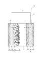
- the dye-sensitized solar cell 100 has a light electrode 10, an electrolyte layer 20, and a counter electrode 30, and the electrolyte layer 20 faces the light electrode 10. It is located between the electrode 30 and the electrode 30.
- the optical electrode 10 is adsorbed on the surface of the semiconductor fine particles of the support 10a, the conductive layer 10b provided on the support 10a, the porous semiconductor fine particle layer 10c made of the semiconductor fine particles, and the porous semiconductor fine particle layer 10c.
- the sensitizing dye layer 10d made of the sensitizing dye is provided, and the porous semiconductor fine particle layer 10c and the sensitizing dye layer 10d are formed on the conductive layer 10b.
- the counter electrode 30 includes a support 30a, a conductive layer 30b provided on the support 30a, and a catalyst layer 30c provided on the conductive layer 30b. Further, the conductive layer 10b of the optical electrode 10 and the conductive layer 30b of the counter electrode 30 are connected via an external circuit 40.
- the dye-sensitized solar cell as the solar cell of the present invention includes the above-mentioned electrode of the present invention as at least one of the optical electrode 10 and the counter electrode 30.
- the dye-sensitized solar cell preferably includes the conductive film of the present invention as the catalyst layer 30c of the counter electrode 30.
- the optical electrode 10 is an electrode that can emit electrons to an external circuit by receiving light. As described above, the optical electrode 10 is provided on the surface of the support 10a, the conductive layer 10b provided on the support, the porous semiconductor fine particle layer 10c made of semiconductor fine particles, and the semiconductor fine particles of the porous semiconductor fine particle layer. It is provided with a sensitizing dye layer 10d made of the adsorbed sensitizing dye.
- the support 10a and the conductive layer 10b of the optical electrode known ones can be used. Specifically, as the support 10a of the optical electrode, the same one as described above can be used as the "support of the counter electrode", and as the conductive layer 10b of the optical electrode, the "conductive layer of the counter electrode". The same as those described above can be used.
- the porous semiconductor fine particle layer 10c of the optical electrode can be formed by using, for example, particles (semiconductor fine particles) of a metal oxide such as titanium oxide, zinc oxide, and tin oxide.
- a metal oxide such as titanium oxide, zinc oxide, and tin oxide.
- One type of metal oxide particles may be used alone, or two or more types may be used in combination.
- the porous semiconductor fine particle layer 10c can be formed by a pressing method, a hydrothermal decomposition method, an electrophoretic electrodeposition method, a binder-free coating method, or the like.
- the sensitizing dye that adsorbs to the surface of the semiconductor fine particles of the porous semiconductor fine particle layer 10c to form the sensitizing dye layer 10d cyanine dye, merocyanine dye, oxonol dye, xanthene dye, squalylium dye, polymethine dye, and coumarin.
- organic dyes such as dyes, riboflavin dyes and perylene dyes; metal complex dyes such as phthalocyanine complexes and porphyrin complexes of metals such as iron, copper and ruthenium; and the like.
- the sensitizing dye one type may be used alone, or two or more types may be used in combination.
- the sensitizing dye layer 10d may be formed by, for example, a method of immersing the porous semiconductor fine particle layer 10c in a solution of the sensitizing dye, a method of applying a solution of the sensitizing dye on the porous semiconductor fine particle layer 10c, or the like. Can be formed.
- the electrolyte layer 20 usually contains a supporting electrolyte, a redox pair (a pair of chemical species that can be reversibly converted into an oxide and a reduced form in the redox reaction), a solvent and the like.
- a redox pair a pair of chemical species that can be reversibly converted into an oxide and a reduced form in the redox reaction
- examples of the supporting electrolyte include salts containing cations such as lithium ion, imidazolium ion, and quaternary ammonium ion. These may be used individually by 1 type and may be used in combination of 2 or more type.
- the redox pair may be any as long as it can reduce the oxidized sensitizing dye, and chlorine compound-chlorine, iodine compound-iodine, bromine compound-bromine, and tallium ion (III) -tallium ion (I).
- a solution (electrolyte solution) containing the constituent components is applied onto the optical electrode 10, a cell having the optical electrode 10 and the counter electrode 30 is prepared, and the electrolytic solution is injected into the gap thereof. It can be formed by squeezing.
- the method for manufacturing a solar cell of the present invention is a method for manufacturing a solar cell in which a first electrode, an electrolyte layer, and a second electrode are laminated and arranged in this order, and the above-mentioned method of the present invention is described on a substrate.
- An aprotonic polar substance is used as a solvent between the step of applying and drying the CNT aqueous dispersion to form a conductive film and forming the first electrode containing the conductive film, and between the first electrode and the second electrode. It is characterized by including a step of forming an electrolyte layer using the electrolytic solution contained in the above.
- the solar cell of the present invention having excellent conversion efficiency can be efficiently manufactured.
- a 5-membered cyclic carbonate such as ethylene carbonate and propylene carbonate (propylene carbonate); a 5-membered cyclic ester such as ⁇ -butyrolactone and ⁇ -valerolactone; acetonitrile, 3-methoxypropio.
- Alibo nitriles such as nitrile and methoxy acetonitrile; aliphatic chain ethers such as dimethoxyethane and triethylene glycol monomethyl ether; aliphatic cyclic ethers such as tetrahydrofuran and dioxane; aliphatic sulfones such as ethyl isopropyl sulfone; cyclic such as sulfone.
- Sulfones; aliphatic sulfoxides such as dimethylsulfoxide; dimethylformamides; aprotonic polar substances such as ethylmethylimidazolium bistrifluoromethylsulfonylimide can be used.
- acetonitrile, ⁇ -butyrolactone, 3-methoxypropionitrile, and triethylene glycol monomethyl ether are preferable as the aprotic polar substance.
- the dispersant contained in the CNT aqueous dispersion of the present invention is soluble in the solvent (aprotic polar substance) contained in the electrolytic solution. If the dispersant contained in the CNT water dispersion is soluble in the solvent, the dispersant, which is a resistance component contained in the conductive film, is eluted from the conductive film in the solar cell. Since it can be removed, the photoelectric conversion efficiency of the solar cell can be further increased.
- the CNT aqueous dispersion of the present invention further contains a thickener, and the thickener is insoluble in the solvent (aprotic polar substance) contained in the electrolytic solution. If the thickener contained in the CNT water dispersion is insoluble in the solvent constituting the electrolytic solution, the thickener exhibits binding ability in the conductive film incorporated in the solar cell. Desorption of the conductive film from the substrate can be suppressed, and as a result, the conversion efficiency of the solar cell can be improved.
- solar cell module By connecting the above-mentioned solar cells of the present invention in series and / or in parallel, a solar cell module can be obtained.
- the solar cells of the present invention are arranged on a flat surface or a curved surface, a non-conductive partition wall is provided between the batteries, and the optical electrode and the counter electrode of each battery are conductive. It can be obtained by electrically connecting using a member.
- the solar cell module including the solar cell of the present invention is excellent in conversion efficiency and reliability.
- the number of solar cells used to form the solar cell module is not particularly limited, and can be appropriately determined according to the target voltage.
- a pseudo-sunlight irradiation device (PEC-L11 type, manufactured by Pexel Technologies Co., Ltd.) in which an AM1.5G filter was attached to a 150 W xenon lamp light source was used. The amount of light was adjusted to 1 sun (AM1.5G, 100mW / cm 2 (JIS C8912 class A)).
- the manufactured dye-sensitized solar cell was connected to a source meter (2400 type source meter, manufactured by Keithley), and the following current-voltage characteristics were measured. Under 1 sun light irradiation, the output current was measured while changing the bias voltage from 0 V to 0.8 V in units of 0.01 V.
- the output current was measured by integrating the values from 0.05 seconds to 0.15 seconds after changing the voltage in each voltage step. A measurement was also performed in which the bias voltage was changed from 0.8 V to 0 V in the reverse direction, and the average value of the measurements in the forward direction and the reverse direction was taken as the photocurrent. From the above measurement results of current-voltage characteristics, short-circuit current density (Jsc; unit is [mA / cm 2 ]), open circuit voltage (Voc; unit is [V]), curve factor (FF; unitless amount), and energy. The conversion efficiency ( ⁇ ; unit is%) was calculated.
- the value of the short-circuit current density (Jsc; unit is [mA / cm 2 ]) corresponds to the catalytic activity of the conductive film
- the value of the curve factor (FF; unitless amount) corresponds to the conductivity of the conductive film.
- Equivalent to. Catalytic activity, conductivity, and conversion efficiency were each evaluated according to the following criteria.
- ⁇ Catalytic activity >> A: 10.0 or more B: 9.0 or more and less than 10.0 C: less than 9.0
- Conductivity A: 0.60 or more B: 0.55 or more and less than 0.60 C: less than 0.55
- Conversion efficiency >> A: 4.0 or more B: 3.5 or more and less than 4.0 C: less than 3.5
- Example 1 ⁇ Preparation of CNT water dispersion> Single-layer CNT (manufactured by Nippon Zeon, product name "SG101"; BET specific surface area: 1264 m 2 / g; G / D ratio: 3.8) 2.0 g, acetylene black (manufactured by Denka, Denka) in a 500 mL polymer.
- the obtained mixture was stirred with a homomixer at 6000 rpm for 30 minutes while cooling the polybin to 25 ° C. to obtain a crude dispersion.
- the obtained crude dispersion was subjected to 10 Pass treatment at 100 MPa with a wet jet mill (manufactured by Yoshida Kikai Kogyo Co., Ltd., product name "NanoVeta (registered trademark)") while cooling the dispersion to 25 ° C, and then CNT water dispersion.
- the CNT aqueous dispersion prepared as described above is applied onto an ITO-PEN film (50 mm ⁇ 50 mm, 15 ⁇ / ⁇ ) by a screen printing method using a 100 mesh screen, and is applied to an inert oven (Yamato Kagaku Co., Ltd.).
- the coating film was formed by drying in an air atmosphere at 125 ° C. for 15 minutes. This coating film is dried at 60 ° C. under reduced pressure for 2 hours, and is provided with a support made of polyethylene naphthalate, an ITO film as a conductive layer, and a conductive film of the present invention as a catalyst layer in this order. Was produced.
- the appearance (film strength) of the conductive film was evaluated using this counter electrode.
- the results are shown in Table 1.
- a ruthenium complex manufactured by Solaronics Co., Ltd .: trade name N719 was used as the sensitizing dye, and ethanol was used as the solvent to prepare a sensitizing dye solution (concentration 0.3 mM).
- An isopropyl alcohol solution of titanium isopropoxide having a concentration of 5 mM is applied on an ITO-PEN film (50 mm ⁇ 50 mm 15 ⁇ / ⁇ ) by the bar coat method, and dried in an inert oven (manufactured by Yamato Scientific Co., Ltd.) at 150 ° C. for 15 minutes. I let you.
- thermosetting Ag paste manufactured by Toyochem Co., Ltd.
- print using a screen printing machine SFA-PC610CTN manufactured by Celia
- heat in an inert oven manufactured by Yamato Kagaku Co., Ltd.
- An electrode thickness 8 ⁇ m
- a water-based titanium oxide paste PECC-AW1-01 manufactured by Pexel Technologies Co., Ltd.
- Pexel Technologies Co., Ltd. a water-based titanium oxide paste
- the ITO-PEN film on which the porous semiconductor layer was formed was placed in a sensitizing dye solution (each vat of 50 cm) prepared as described above, and immersed at 40 ° C. for 2 hours. After the immersion, the mixture was washed with an ethanol solution and dried under reduced pressure at 40 ° C. for 24 hours to prepare a photoelectrode.
- a sensitizing dye solution each vat of 50 cm
- iodine is 0.05 mol / L
- lithium iodide is 0.1 mol / L
- t-butyl pyridine is 0.5 mol / L
- 1,2-dimethyl-3propylimidazolium iodide is 0.6 mol / L.
- acetonitrile as a solvent to obtain an electrolytic solution.
- the electrolytic solution obtained as described above was applied to the optical electrode.
- the counter electrode was installed in a vacuum bonding device, superposed in a vacuum, UV irradiation was performed with a metal halide lamp at an integrated light intensity of 3000 mJ / cm 2 , and the encapsulant was cured to perform bonding.
- a dye-sensitized solar cell as a solar cell was manufactured by opening the vacuum to atmospheric pressure. Then, using this solar cell, the catalytic activity, conductivity, and conversion efficiency were evaluated. The results are shown in Table 1.
- Example 2 In the preparation of the CNT aqueous dispersion, various operations and the same operations as in Example 1 were performed except that the blending amount of acetylene black was halved and the mass ratio (acetylene black / single-walled carbon nanotube) was changed to 0.5. Evaluation was performed. The results are shown in Table 1.
- Example 3 In preparing the CNT aqueous dispersion, 0.4 g of acetylene black (manufactured by Denka, Denka Black (registered trademark), "FX-35", average particle size: 23 nm, BET specific surface area: 133 m 2 / g) was blended. The same operations and evaluations as in Example 1 were performed except that the mass ratio (acetylene black / single-walled carbon nanotube) was set to 0.2. The results are shown in Table 1.
- Example 4 Same as Example 1 except that 2.0 g of single-walled CNT (manufactured by Kusumoto Kasei Co., Ltd., "TUBALL (registered trademark)", BET specific surface area: 1192 m 2 / g, G / D ratio: 62.8) was blended. Various operations and evaluations were performed. The results are shown in Table 1.
- Example 1 (Comparative Example 1) Various operations and evaluations similar to those in Example 1 were performed except that acetylene black was not blended. The results are shown in Table 1.
- Example 2 Various operations and evaluations similar to those in Example 1 were performed except that the blending amount of acetylene black was changed to 3.0 g so that the mass ratio (acetylene black / single-walled carbon nanotube) was 1.5. .. The results are shown in Table 1.
- Example 4 (Comparative Example 4) Example 1 and Example 1 except that 2.0 g of multi-walled CNT (manufactured by KUMHO, "K-nanos", BET specific surface area: 245 m 2 / g, G / D ratio: 0.8) was blended instead of the single-walled CNT. Similar operations and evaluations were performed. The results are shown in Table 1.
- Example 5 Same as Example 1 except that 2.0 g of multi-walled CNT (manufactured by Nanocil, "NC7000", BET specific surface area: 234 m 2 / g, G / D ratio: 0.6) was blended instead of the single-walled CNT. Various operations and evaluations were performed. The results are shown in Table 1.
- SGCNT indicates “SG101” which is a single-walled CNT manufactured by Zeon Corporation.
- Tuball indicates “TUBALL (registered trademark)” which is a single-walled CNT manufactured by Kusumoto Kasei Co., Ltd.
- K-nanos indicates “K-nanos” which is a multi-walled CNT manufactured by KUMHO.
- NC7000 indicates “NC7000” which is a multi-walled CNT manufactured by Nanocyl.
- HS-100 indicates “Denka Black (registered trademark) HS-100” which is an acetylene black manufactured by Denka Co., Ltd.
- FX-35 indicates "Denka Black (registered trademark) FX-35” which is an acetylene black manufactured by Denka Co., Ltd.
- ECP refers to "carbon ECP", which is a Ketjen black manufactured by Lion Specialty Chemicals.
- a carbon nanotube aqueous dispersion liquid which is excellent in conductivity and catalytic activity when used as a catalyst layer and can form a conductive film capable of exhibiting excellent conversion efficiency in a solar cell. ..
- a conductive film having excellent conductivity and catalytic activity when used as a catalyst layer and capable of exhibiting excellent conversion efficiency in a solar cell it is possible to provide an electrode capable of exhibiting excellent conversion efficiency in a solar cell. According to the present invention, it is possible to provide a solar cell having excellent conversion efficiency.
Landscapes
- Chemical & Material Sciences (AREA)
- Engineering & Computer Science (AREA)
- Materials Engineering (AREA)
- Nanotechnology (AREA)
- Organic Chemistry (AREA)
- Inorganic Chemistry (AREA)
- Power Engineering (AREA)
- Microelectronics & Electronic Packaging (AREA)
- Sustainable Energy (AREA)
- Physics & Mathematics (AREA)
- Condensed Matter Physics & Semiconductors (AREA)
- Electromagnetism (AREA)
- General Physics & Mathematics (AREA)
- Computer Hardware Design (AREA)
- Sustainable Development (AREA)
- Life Sciences & Earth Sciences (AREA)
- Carbon And Carbon Compounds (AREA)
- Hybrid Cells (AREA)
- Photovoltaic Devices (AREA)
Abstract
Description
また、例えば特許文献2では、CNTではないが、導電性炭素材料であるカーボンブラック及び繊維状炭素材料を用いて、触媒層を形成することが検討されている。実際に特許文献2では、カーボンブラックと、繊維状炭素材料と、有機バインダとを含み、カーボンブラックの含有質量Aと繊維状炭素材料Bとの質量比(B/A)が、10/90以上50/50以下の範囲内である対向電極を備える、光電変換素子が開示されている。より詳細には、カーボンブラック、気相成長炭素繊維、及びポリフッ化ビニリデンをN-メチルピロリドンと混合し、スラリーとして、かかるスラリーを基盤表面に塗工及び乾燥して得た導電膜を触媒層とする対向電極を備える色素増感型太陽電池について具体的に検討されている。 For example, Patent Document 1 discloses a catalyst layer containing carbon nanotubes satisfying predetermined attributes and conductive carbon different from the carbon nanotubes. More specifically, in Patent Document 1, a dye-sensitized solar cell using a counter electrode having a conductive film formed by using an aqueous dispersion containing single-walled carbon nanotubes and Ketjen black as a catalyst layer is specified. Is being considered.
Further, for example, in Patent Document 2, it is studied to form a catalyst layer by using carbon black and a fibrous carbon material, which are conductive carbon materials, although they are not CNTs. In fact, Patent Document 2 includes carbon black, a fibrous carbon material, and an organic binder, and the mass ratio (B / A) of the carbon black content A and the fibrous carbon material B is 10/90 or more. A photoelectric conversion element having a counter electrode within the range of 50/50 or less is disclosed. More specifically, carbon black, vapor-grown carbon fiber, and polyvinylidene fluoride are mixed with N-methylpyrrolidone to form a slurry, and the conductive film obtained by applying and drying the slurry on the surface of the substrate is used as a catalyst layer. A dye-sensitized solar cell provided with a counter electrode is specifically studied.
また、本発明は、導電性及び触媒層として用いた場合の触媒活性に優れるとともに、太陽電池に優れた変換効率を発揮させ得る導電膜の提供を目的とする。
更に、本発明は、太陽電池に優れた変換効率を発揮させ得る電極の提供を目的とする。
そして、本発明は、変換効率に優れる太陽電池及びその製造方法の提供を目的とする。 Therefore, an object of the present invention is to provide a carbon nanotube aqueous dispersion capable of forming a conductive film having excellent conductivity and catalytic activity when used as a catalyst layer and capable of exhibiting excellent conversion efficiency in a solar cell. ..
Another object of the present invention is to provide a conductive film having excellent conductivity and catalytic activity when used as a catalyst layer and capable of exhibiting excellent conversion efficiency in a solar cell.
Furthermore, it is an object of the present invention to provide an electrode capable of exerting excellent conversion efficiency in a solar cell.
An object of the present invention is to provide a solar cell having excellent conversion efficiency and a method for manufacturing the same.
なお、本明細書において、ある化合物(分散剤、増粘剤)が溶媒(非プロトン性極性物質)に対して「溶解性」であるとは、温度23℃において当該溶媒に1質量%の濃度で溶解する(不溶分が目視で確認できない)ことをいい、「非溶解性」であるとは、温度23℃において当該溶媒に1質量%の濃度で、24時間撹拌後も溶解しない(不溶分が目視で確認できる)ことをいう。 Here, in the method for manufacturing a solar cell of the present invention, it is preferable that the dispersant contained in the carbon nanotube water dispersion is soluble in the solvent contained in the electrolyte. If the dispersant contained in the carbon nanotube water dispersion is soluble in the solvent constituting the electrolytic solution, the dispersant, which is a resistance component contained in the conductive film, is added to the electrolytic solution in the solar cell. Since it can be eluted and removed from the conductive film, the photoelectric conversion efficiency of the obtained solar cell can be further increased.
In the present specification, a certain compound (dispersant, thickener) is "soluble" in a solvent (aprotonic polar substance) at a concentration of 1% by mass in the solvent at a temperature of 23 ° C. It means that it dissolves in (the insoluble content cannot be visually confirmed), and "insoluble" means that it does not dissolve in the solvent at a concentration of 1% by mass at a temperature of 23 ° C. even after stirring for 24 hours (insoluble content). Can be visually confirmed).
また、本発明によれば、導電性及び触媒層として用いた場合の触媒活性に優れるとともに、太陽電池に優れた変換効率を発揮させ得る導電膜を提供することができる。
更に、本発明によれば、太陽電池に優れた変換効率を発揮させ得る電極を提供することができる。
そして、本発明によれば、変換効率に優れる太陽電池及びその製造方法を提供することができる。 According to the present invention, it is possible to provide a carbon nanotube aqueous dispersion liquid which is excellent in conductivity and catalytic activity when used as a catalyst layer and can form a conductive film capable of exhibiting excellent conversion efficiency in a solar cell. ..
Further, according to the present invention, it is possible to provide a conductive film having excellent conductivity and catalytic activity when used as a catalyst layer and capable of exhibiting excellent conversion efficiency in a solar cell.
Further, according to the present invention, it is possible to provide an electrode capable of exhibiting excellent conversion efficiency in a solar cell.
According to the present invention, it is possible to provide a solar cell having excellent conversion efficiency and a method for manufacturing the same.
本発明のCNT水分散液は、単層カーボンナノチューブ、アセチレンブラック、分散剤および水を含み、必要に応じて、その他の成分を更に含む。カーボンナノチューブ水分散液においては、単層カーボンナノチューブとアセチレンブラックとの含有割合が、質量比(アセチレンブラック/単層カーボンナノチューブ)で1.4以下であることを必要とする。 (Carbon nanotube water dispersion)
The CNT water dispersion of the present invention contains single-walled carbon nanotubes, acetylene black, a dispersant and water, and if necessary, further contains other components. In the carbon nanotube aqueous dispersion, the content ratio of the single-walled carbon nanotubes and the acetylene black needs to be 1.4 or less in terms of mass ratio (acetylene black / single-walled carbon nanotubes).
単層CNTは、多層CNTと比較して、配合量に対する比表面積の値が大きい。そのため、単層CNTは、当該単層CNTを含む導電膜の、触媒層としての触媒活性を高めることができる。そして、単層CNTは、1種単独で使用してもよいし、2種以上を併用してもよい。 <Single-walled carbon nanotubes>
The single-walled CNT has a larger specific surface area value with respect to the blending amount than the multi-walled CNT. Therefore, the single-walled CNT can enhance the catalytic activity of the conductive film containing the single-walled CNT as a catalytic layer. The single-walled CNT may be used alone or in combination of two or more.
なお、本発明において、「カーボンナノチューブの平均直径」は、透過型電子顕微鏡(TEM)画像上で、例えば、20本のCNTについて直径(外径)を測定し、個数平均値を算出することで求めることができる。 The average diameter of the single-walled CNTs is preferably 1 nm or more, more preferably 2 nm or more, more preferably 10 nm or less, and even more preferably 6 nm or less. When the average diameter of the single-walled CNTs is 1 nm or more, the dispersibility of the single-walled CNTs can be enhanced, and characteristics such as conductivity can be stably imparted to the conductive film. Further, when the average diameter of the single-walled CNT is 10 nm or less, the catalytic activity can be further enhanced when the conductive film is used as the catalyst layer.
In the present invention, the "average diameter of carbon nanotubes" is determined by measuring the diameter (outer diameter) of 20 CNTs on a transmission electron microscope (TEM) image and calculating the average number. You can ask.
なお、単層CNTの平均直径(Av)及び標準偏差(σ)は、単層CNTの製造方法や製造条件を変更することにより調整してもよいし、異なる製法で得られた単層CNTを複数種類組み合わせることにより調整してもよい。 Further, as a single-layer CNT, the ratio (3σ / Av) of the value (3σ) obtained by multiplying the standard deviation (σ: sample standard deviation) of the diameter by 3 with respect to the average diameter (Av) is more than 0.20 0.80. It is preferable to use a CNT of less than, more preferably a single layer CNT having a 3σ / Av of more than 0.25, and particularly preferably a CNT having a 3σ / Av of more than 0.40. If a single-walled CNT having 3σ / Av of more than 0.20 and less than 0.80 is used, the performance of the produced conductive film can be further improved.
The average diameter (Av) and standard deviation (σ) of the single-walled CNTs may be adjusted by changing the manufacturing method and manufacturing conditions of the single-walled CNTs, or single-walled CNTs obtained by different manufacturing methods may be used. It may be adjusted by combining a plurality of types.
なお、本発明において、「カーボンナノチューブの平均長さ」は、走査型電子顕微鏡(SEM)画像上で、例えば、20本の単層CNTについて長さを測定し、算術平均値を算出することで求めることができる。 The average length of the single-walled CNT is preferably 10 μm or more, more preferably 50 μm or more, particularly preferably 80 μm or more, preferably 600 μm or less, and preferably 500 μm or less. It is more preferable, and it is particularly preferable that it is 400 μm or less. When the average length is 10 μm or more, a conductive path can be formed in the conductive film with a small blending amount, and the strength of the conductive film is high. When the average length is 600 μm or less, the applicability to the substrate can be improved when the dispersion liquid is applied. Therefore, if the average length of the single-walled CNTs is within the above range, the surface resistivity of the conductive film can be sufficiently lowered and high catalytic activity can be imparted to the conductive film.
In the present invention, the "average length of carbon nanotubes" is determined by measuring the length of, for example, 20 single-walled CNTs on a scanning electron microscope (SEM) image and calculating an arithmetic mean value. You can ask.
なお、本発明において、「BET比表面積」とは、BET法を用いて測定した窒素吸着比表面積を指す。 The BET specific surface area of the single-layer CNT is preferably 400 m 2 / g or more, more preferably 600 m 2 / g or more, further preferably 800 m 2 / g or more, and 2000 m 2 / g or less. It is preferably 1800 m 2 / g or less, and even more preferably 1600 m 2 / g or less. When the BET specific surface area of the single-walled CNT is 400 m 2 / g or more, the dispersibility of the single-walled CNT is enhanced, and when the single-walled CNT is used as an electrode for a solar cell and a conductive film obtained with a small blending amount. It is possible to impart characteristics such as catalytic activity in the above. Further, when the BET specific surface area of the single-walled CNT is 2000 m 2 / g or less, the obtained conductive film can be imparted with properties such as conductivity and catalytic activity when used as an electrode for a solar cell. In addition, the coatability of the CNT water dispersion can be stabilized.
In the present invention, the "BET specific surface area" refers to the nitrogen adsorption specific surface area measured by the BET method.
そして、スーパーグロース法により製造された単層CNTの集合体は、SGCNTのみから構成されていてもよいし、SGCNTに加え、例えば、非円筒形状の炭素ナノ構造体等の他の炭素ナノ構造体を含んでいてもよい。 The single-walled CNT can be produced by using a known single-walled CNT synthesis method such as an arc discharge method, a laser ablation method, or a chemical vapor deposition method (CVD method) without particular limitation. .. Specifically, for single-walled CNTs, for example, a raw material compound and a carrier gas are supplied on a substrate having a catalyst layer for CNT production on the surface, and CNTs are synthesized by a chemical vapor deposition method (CVD method). In accordance with the method of dramatically improving the catalytic activity of the catalyst layer by allowing a trace amount of oxidizing agent (catalyst activator) to be present in the system (super growth method; see International Publication No. 2006/011655). It can be manufactured efficiently. In the following, the carbon nanotubes obtained by the super growth method may be referred to as "SGCNT".
The aggregate of single-walled CNTs produced by the super-growth method may be composed of only SGCNTs, or in addition to SGCNTs, for example, other carbon nanostructures such as non-cylindrical carbon nanostructures. May include.
アセチレンブラックとは、アセチレンガスを熱分解して得られるカーボンブラックの一種であり、概して、高純度かつ球形の一次炭素微粒子が連なってなる構造を有している。CNT水分散液が単層CNTに加えて、アセチレンブラックを含有することで、得られる導電膜の導電性が高まる。その理由は明らかではないが、アセチレンブラックは、他のカーボンブラックに比べて高純度かつストラクチャ構造が著しく発達していることに起因した高い導電性を示すため、単層CNTと相乗効果を呈することで、良好な導電ネットワークを形成することができるためであると推察される。 <Acetylene Black>
Acetylene black is a kind of carbon black obtained by thermally decomposing acetylene gas, and generally has a structure in which high-purity and spherical primary carbon fine particles are connected. When the CNT water dispersion liquid contains acetylene black in addition to the single-walled CNT, the conductivity of the obtained conductive film is enhanced. Although the reason is not clear, acetylene black has a synergistic effect with single-walled CNTs because it exhibits high purity and high conductivity due to the significantly developed structure structure compared to other carbon blacks. Therefore, it is presumed that this is because a good conductive network can be formed.
分散剤としては、特に限定されることなく、上述した単層CNTを水中で分散させ得る化合物が挙げられる。例えば、分散剤としては、スチレンとメトキシポリエチレングリコールメタクリレートとの共重合体、ポリビニルピロリドン、ポリオキシエチレン=アルキルエーテル(アルキル基の炭素数は、好ましくは8以上20以下である。)、ポリオキシエチレン=アルキルフェニルエーテル(アルキル基の炭素数は、好ましくは8以上9以下である。)が挙げられる。なお分散剤は、1種を単独で用いてもよく、2種以上を組み合わせて用いてもよい。 <Dispersant>
The dispersant is not particularly limited, and examples thereof include compounds capable of dispersing the above-mentioned single-walled CNTs in water. For example, examples of the dispersant include a copolymer of styrene and methoxypolyethylene glycol methacrylate, polyvinylpyrrolidone, polyoxyethylene = alkyl ether (the number of carbon atoms of the alkyl group is preferably 8 or more and 20 or less), and polyoxyethylene. = Alkyl phenyl ether (the number of carbon atoms of the alkyl group is preferably 8 or more and 9 or less). The dispersant may be used alone or in combination of two or more.
また、スチレンとメトキシポリエチレングリコールメタクリレートとの共重合体は、導電膜の導電性及び触媒層として用いた場合の触媒活性を一層向上させつつ、太陽電池の変換効率を更に高める観点から、重量平均分子量が10000以上30000以下であることが好ましい。
なお、本発明において、重量平均分子量は、ゲル浸透クロマトグラフィーを用いて測定することができる。 The copolymer of styrene and methoxypolyethylene glycol methacrylate further improves the conductivity of the conductive film and the catalytic activity when used as a catalyst layer, and further enhances the conversion efficiency of the solar cell. The n (integer) of the ethylene glycol chain portion “( CH2 - CH2 -O) n )” of the repeating unit derived from methacrylate is preferably 2 or more and 45 or less, and more preferably 9 or more and 23 or less. preferable.
Further, the copolymer of styrene and methoxypolyethylene glycol methacrylate further improves the conductivity of the conductive film and the catalytic activity when used as a catalyst layer, and further enhances the conversion efficiency of the solar cell, and has a weight average molecular weight. Is preferably 10,000 or more and 30,000 or less.
In the present invention, the weight average molecular weight can be measured by using gel permeation chromatography.
これらは、1種単独で使用してもよいし、2種以上を併用してもよい。そしてこれらの中でも、アセトニトリル、γ-ブチロラクトン、3-メトキシプロピオニトリル、及びトリエチレングリコールモノメチルエーテルが好ましい。 Here, examples of the aprotonic polar substance used as the solvent of the electrolytic solution include 5-membered cyclic carbonates such as ethylene carbonate and propylene carbonate (propylene carbonate); 5-membered cyclic carbonates such as γ-butyrolactone and γ-valerolactone. Esters; aliphatic nitriles such as acetonitrile, 3-methoxypropionitrile, and methoxy acetonitrile; aliphatic chain ethers such as dimethoxyethane and triethylene glycol monomethyl ether; aliphatic cyclic ethers such as tetrahydrofuran and dioxane; ethyl isopropyl sulfone and the like. Alibrous sulfones; cyclic sulfones such as sulfolanes; aliphatic sulfoxides such as dimethylsulfoxides; dimethylformamides; ethylmethylimidazolium bistrifluoromethylsulfonylimides;
These may be used alone or in combination of two or more. Among these, acetonitrile, γ-butyrolactone, 3-methoxypropionitrile, and triethylene glycol monomethyl ether are preferable.
また、少なくともトリエチレングリコールモノメチルエーテルに対して溶解性の分散剤としては、例えば、スチレンとメトキシポリエチレングリコールメタクリレートとの共重合体、ポリビニルピロリドンが挙げられる。 Examples of the dispersant soluble in at least acetonitrile, γ-butyrolactone, and 3-methoxypropionitrile include the above-mentioned copolymer of styrene and methoxypolyethylene glycol methacrylate, polyvinylpyrrolidone, and polyoxyethylene = alkyl ether ( The number of carbon atoms of the alkyl group is preferably 8 or more and 20 or less), and polyoxyethylene = alkylphenyl ether (the number of carbon atoms of the alkyl group is preferably 8 or more and 9 or less).
Examples of the dispersant soluble in at least triethylene glycol monomethyl ether include polyvinylpyrrolidone, which is a copolymer of styrene and methoxypolyethylene glycol methacrylate.
CNT水分散液に任意に添加することができる増粘剤としては、特に限定されることなく、CNT水分散液に粘性を付与し得る化合物が挙げられる。CNT水分散液が増粘剤を含有していれば、得られる太陽電池の変換効率を一層向上させ得る。例えば、増粘剤としては、セルロース系ポリマー(ヒドロキシエチルセルロース、カルボキシメチルセルロースなど)、ポリエチレンオキサイド、ポリビニルアルコールが挙げられる。なお増粘剤は、1種を単独で用いてもよく、2種以上を組み合わせて用いてもよい。 <Thickener>
The thickener that can be arbitrarily added to the CNT aqueous dispersion is not particularly limited, and examples thereof include compounds that can impart viscosity to the CNT aqueous dispersion. If the CNT water dispersion liquid contains a thickener, the conversion efficiency of the obtained solar cell can be further improved. For example, examples of the thickener include cellulosic polymers (hydroxyethyl cellulose, carboxymethyl cellulose, etc.), polyethylene oxide, and polyvinyl alcohol. The thickener may be used alone or in combination of two or more.
ここで、少なくともアセトニトリルに対して非溶解性の増粘剤としては、例えば、セルロース系ポリマー(ヒドロキシエチルセルロース、カルボキシメチルセルロースなど)、ポリビニルアルコールが挙げられる。
また、少なくともγ-ブチロラクトン、3-メトキシプロピオニトリルに対して非溶解性の増粘剤としては、例えば、セルロース系ポリマー(ヒドロキシエチルセルロース、カルボキシメチルセルロースなど)、ポリエチレンオキサイド、ポリビニルアルコールが挙げられる。
さらに、少なくともトリエチレングリコールモノメチルエーテルに対して非溶解性の増粘剤としては、例えば、セルロース系ポリマー(ヒドロキシエチルセルロース、カルボキシメチルセルロースなど)、ポリエチレンオキサイドが挙げられる。 Further, the CNT aqueous dispersion of the present invention can be suitably used for forming an electrode of a solar cell including an electrolytic solution containing an aprotic polar substance as a solvent. In this case, the above-mentioned solvent can be used. On the other hand, it is preferable to use a thickener that is insoluble. If the thickener contained in the CNT water dispersion is insoluble in the solvent constituting the electrolytic solution, the thickener exhibits binding ability in the conductive film incorporated in the solar cell. Desorption of the conductive film from the substrate can be suppressed, and as a result, the conversion efficiency of the solar cell can be improved.
Here, examples of the thickener insoluble in acetonitrile include cellulosic polymers (hydroxyethyl cellulose, carboxymethyl cellulose, etc.) and polyvinyl alcohol.
Examples of the thickener insoluble in at least γ-butyrolactone and 3-methoxypropionitrile include cellulosic polymers (hydroxyethyl cellulose, carboxymethyl cellulose, etc.), polyethylene oxide, and polyvinyl alcohol.
Further, examples of the thickener insoluble in at least triethylene glycol monomethyl ether include cellulosic polymers (hydroxyethyl cellulose, carboxymethyl cellulose, etc.) and polyethylene oxide.
溶媒としては、少なくとも水を用いる必要があるが、水と、水と混和する溶媒との混合溶媒を用いてもよい。水と混和する溶媒としては、例えば、エーテル類(ジオキサン、テトラヒドロフラン、メチルセロソルブ、エチレングリコールジメチルエーテル、エチレングリコールブチルエーテル等)、エーテルアルコール(エトキシエタノール、メトキシエトキシエタノール等)、エステル類(酢酸メチル、酢酸エチル等)、ケトン類(アセトン、メチルイソブチルケトン、シクロヘキサノン、メチルエチルケトン等)、アルコール類(メタノール、エタノール、イソプロパノール、プロピレングリコール、エチレングリコール、ジアセトンアルコール、フェノール等)、低級カルボン酸(酢酸等)、アミン類(トリエチルアミン、トリメタノールアミン等)、窒素含有極性溶媒(N,N-ジメチルホルムアミド、ニトロメタン、N-メチルピロリドン、アセトニトリル等)、硫黄化合物類(ジメチルスルホキシド等)を挙げることができる。これらは、1種を単独で用いてもよく、2種以上を組み合わせて用いてもよい。 <Solvent>
As the solvent, at least water needs to be used, but a mixed solvent of water and a solvent miscible with water may be used. Examples of the solvent to be mixed with water include ethers (dioxane, tetrahydrofuran, methyl cellosolve, ethylene glycol dimethyl ether, ethylene glycol butyl ether, etc.), ether alcohols (ethoxyethanol, methoxyethoxyethanol, etc.), esters (methyl acetate, ethyl acetate, etc.). Etc.), Ketones (acetone, methylisobutylketone, cyclohexanone, methylethylketone, etc.), alcohols (methanol, ethanol, isopropanol, propylene glycol, ethylene glycol, diacetone alcohol, phenol, etc.), lower carboxylic acids (acetic acid, etc.), amines (Triethylamine, Trimethanolamine, etc.), nitrogen-containing polar solvents (N, N-dimethylformamide, nitromethane, N-methylpyrrolidone, acetonitrile, etc.), sulfur compounds (dimethylsulfoxide, etc.) can be mentioned. These may be used individually by 1 type and may be used in combination of 2 or more type.
その他の成分としては、シリカ等の無機物、金属粒子、結着剤、導電助剤、界面活性化剤、消泡剤、老化防止剤、防腐剤等が挙げられる。これらは、既知のものを適宜使用すればよい。またこれらは、1種を単独で用いてもよく、2種以上を組み合わせて用いてもよい。 <Other ingredients>
Examples of other components include inorganic substances such as silica, metal particles, binders, conductive aids, surfactants, antifoaming agents, antiaging agents, preservatives and the like. As these, known ones may be used as appropriate. Further, these may be used alone or in combination of two or more.
CNT水分散液の調製方法は特に限定されず、例えば、水を含む溶媒の存在下、単層CNT、アセチレンブラック、及び分散剤、並びに必要に応じて用いられるその他成分に対して既知の混合・分散処理を施すことで単層CNTの水分散液を得ることができる。既知の混合・分散処理としては、例えば、ナノマイザーやアルティマイザーなど湿式ジェットミル、高圧ホモジナイザー、超音波分散機、ボールミル、サンドグラインダー、ダイノミル、スパイクミル、DCPミル、バスケットミル、ペイントコンディショナー、ホモミキサー等の高速撹拌装置などを用いる方法が挙げられる。
混合・分散処理を行う際の温度は、特に限定されないが、通常、水を含む溶媒の沸点以下であり、好ましくは60℃以下、より好ましくは40℃以下、好ましくは-10℃以上、より好ましくは0℃以上である。この範囲であれば、単層CNTの分散性を向上させることができる。 <Preparation method>
The method for preparing the CNT aqueous dispersion is not particularly limited, and for example, in the presence of a solvent containing water, known mixing / mixing with a single layer CNT, acetylene black, and a dispersant, and other components used as necessary. By performing the dispersion treatment, an aqueous dispersion of a single-layer CNT can be obtained. Known mixing / dispersing treatments include, for example, wet jet mills such as nanomizers and ultimateizers, high-pressure homogenizers, ultrasonic dispersers, ball mills, sand grinders, dyno mills, spike mills, DCP mills, basket mills, paint conditioners, homomixers, etc. A method using a high-speed stirring device or the like can be mentioned.
The temperature at the time of performing the mixing / dispersion treatment is not particularly limited, but is usually not more than the boiling point of the solvent containing water, preferably 60 ° C. or lower, more preferably 40 ° C. or lower, preferably −10 ° C. or higher, more preferably. Is above 0 ° C. Within this range, the dispersibility of the single-walled CNT can be improved.
なお、CNT水分散液のpHを下げるためには、酸性物質を添加すればよい。酸性物質としては、例えば、硫酸、塩酸、硝酸、クエン酸、シュウ酸、酒石酸、ギ酸、リン酸、などが挙げられる。 The pH of the CNT aqueous dispersion is not particularly limited, but is preferably 0.1 or more, more preferably 0.2 or more, particularly preferably 0.5 or more, and less than 7 ( That is, it is preferably acidic), more preferably 6 or less, further preferably 5 or less, further preferably 4 or less, and particularly preferably 3 or less. By setting the pH of the CNT water dispersion within the above range, the stability of the CNT water dispersion can be improved.
In order to lower the pH of the CNT aqueous dispersion, an acidic substance may be added. Examples of the acidic substance include sulfuric acid, hydrochloric acid, nitric acid, citric acid, oxalic acid, tartrate acid, formic acid, phosphoric acid and the like.
本発明の導電膜は、上述した本発明のCNT水分散液を用いて形成される。そして、本発明の導電膜は、本発明のCNT水分散液から形成されているので、導電性及び触媒層として用いた場合の触媒活性に優れる。
そして、本発明の導電膜は、太陽電池の電極(光電極、対向電極)を構成する部材として好適に用いることができ、中でも、対向電極を構成する部材として好適に用いることができる。 (Conducting film)
The conductive film of the present invention is formed by using the above-mentioned CNT aqueous dispersion of the present invention. Since the conductive film of the present invention is formed from the CNT aqueous dispersion of the present invention, it is excellent in conductivity and catalytic activity when used as a catalyst layer.
The conductive film of the present invention can be suitably used as a member constituting an electrode (optical electrode, counter electrode) of a solar cell, and above all, can be suitably used as a member constituting a counter electrode.
本発明の導電膜の厚みは、特に限定されないが、通常、100nm以上1mm以下である。そして、太陽電池(特には、色素増感型太陽電池)の電極として用いる場合の、導電膜の厚みは、0.01μm以上100μm以下であることが好ましく、0.1μm以上20μm以下であることがより好ましく、0.5μm以上10μm以下であることがさらに好ましい。導電膜の厚みが上述した範囲内であれば、電極としての導電性と触媒性能に優れ、また、複数の太陽電池(セル)を相互に接続して太陽電池モジュールとした場合に全体の直列抵抗等のバランスに優れる。 <Characteristics>
The thickness of the conductive film of the present invention is not particularly limited, but is usually 100 nm or more and 1 mm or less. When used as an electrode of a solar cell (particularly, a dye-sensitized solar cell), the thickness of the conductive film is preferably 0.01 μm or more and 100 μm or less, and 0.1 μm or more and 20 μm or less. It is more preferably 0.5 μm or more and 10 μm or less. If the thickness of the conductive film is within the above range, the conductivity as an electrode and the catalytic performance are excellent, and when a plurality of solar cells (cells) are connected to each other to form a solar cell module, the overall series resistance Excellent balance.
本発明の導電膜を製造する方法は、上述した本発明のCNT水分散液を用いる方法であれば特に限定されない。本発明の導電膜は、例えば、CNT水分散液を基材上に塗布する工程(塗布工程)と、基材上のCNT水分散液を乾燥する工程(乾燥工程)とを経て製造することができる。なお、当該製造方法は、塗布工程及び乾燥工程以外の工程(その他の工程)を含んでいてもよい。 <Manufacturing method>
The method for producing the conductive film of the present invention is not particularly limited as long as it is the method using the above-mentioned CNT aqueous dispersion of the present invention. The conductive film of the present invention can be produced, for example, through a step of applying a CNT aqueous dispersion on a substrate (coating step) and a step of drying the CNT aqueous dispersion on the substrate (drying step). can. The manufacturing method may include steps (other steps) other than the coating step and the drying step.
塗布工程では、上述した本発明のCNT水分散液を基材上に塗布する。 <Applying process>
In the coating step, the above-mentioned CNT aqueous dispersion of the present invention is coated on the substrate.
例えば、ディッピング法、ロールコート法、グラビアコート法、ナイフコート法、エアナイフコート法、ロールナイフコート法、ダイコート法、スクリーン印刷法、スプレーコート法、グラビアオフセット法、インクジェット法、噴霧法等が挙げられる。これらの中でも、スクリーン印刷法が好ましい。
また塗布は、1回だけでなく必要に応じて何度か行ってもよく、異なる2種類の塗布方法を組み合わせてもよい。 Then, as a method of applying the CNT water dispersion liquid on the substrate, a known application method can be adopted.
Examples thereof include a dipping method, a roll coating method, a gravure coating method, a knife coating method, an air knife coating method, a roll knife coating method, a die coating method, a screen printing method, a spray coating method, a gravure offset method, an inkjet method, and a spraying method. .. Among these, the screen printing method is preferable.
Further, the coating may be performed not only once but several times as needed, or two different coating methods may be combined.
また、CNT水分散液を基材上に塗布する際の、基材の単位面積当たりのCNTの塗布量としては、0.001mg/m2以上であることが好ましく、0.005mg/m2以上であることがより好ましく、0.01mg/m2以上であることが特に好ましく、50g/m2以下であることが好ましく、10g/m2以下であることがより好ましく、3g/m2以下であることが特に好ましい。 The coating thickness (wet thickness) when the CNT aqueous dispersion is applied onto the substrate is not particularly limited as long as the conductivity of the obtained conductive film is ensured, but is preferably 0.001 μm or more, and is 0. It is more preferably .005 μm or more, particularly preferably 0.01 μm or more, preferably 500 μm or less, more preferably 300 μm or less, and particularly preferably 200 μm or less.
Further, when the CNT aqueous dispersion is applied onto the substrate, the amount of CNT applied per unit area of the substrate is preferably 0.001 mg / m 2 or more, preferably 0.005 mg / m 2 or more. It is more preferably 0.01 mg / m 2 or more, particularly preferably 50 g / m 2 or less, more preferably 10 g / m 2 or less, and 3 g / m 2 or less. It is particularly preferable to have.
乾燥工程では、塗布工程において基材上に形成されたCNT水分散液の塗膜を乾燥して、CNT水分散液の乾燥膜と、基材とを備える積層体を得る。 <Drying process>
In the drying step, the coating film of the CNT water dispersion liquid formed on the base material in the coating step is dried to obtain a laminate having the dried film of the CNT water dispersion liquid and the base material.
乾燥温度は、水を含む溶媒の気化による除去が可能であり、かつ、基材が変形しない温度であれば特に限定されない。乾燥温度は、0℃以上であることが好ましく、15℃以上であることがより好ましく、25℃以上であることがさらに好ましく、80℃以上であることが特に好ましく、250℃以下であることが好ましく、200℃以下であることがより好ましく、150℃以下であることが特に好ましい。
乾燥時間は、特に限定されないが、0.1分間以上であることが好ましく、150分間以下であることが好ましい。
乾燥雰囲気は、加湿雰囲気、大気中、窒素、アルゴンなどの不活性ガス中、真空など減圧化など特に限定されない。 Here, the method for drying the CNT aqueous dispersion on the substrate is not particularly limited, and a known drying method can be adopted. Examples of such a drying method include an air-drying method, a heat-drying method such as a heat roll drying method, a vacuum drying method, an infrared irradiation method, a light irradiation method such as a xenon lamp and a flash lamp, and an electromagnetic wave heating method such as microwaves. Be done.
The drying temperature is not particularly limited as long as it can be removed by vaporization of a solvent containing water and the substrate is not deformed. The drying temperature is preferably 0 ° C. or higher, more preferably 15 ° C. or higher, further preferably 25 ° C. or higher, particularly preferably 80 ° C. or higher, and more preferably 250 ° C. or lower. It is preferably 200 ° C. or lower, more preferably 150 ° C. or lower, and particularly preferably 150 ° C. or lower.
The drying time is not particularly limited, but is preferably 0.1 minutes or more, and preferably 150 minutes or less.
The dry atmosphere is not particularly limited to a humid atmosphere, an atmosphere, an inert gas such as nitrogen or argon, or a vacuum or the like to reduce the pressure.
その他の工程としては、特に限定されないが、上述した乾燥工程を経て得られるCNT水分散液の乾燥膜を洗浄用溶媒で洗浄する工程(洗浄工程)が挙げられる。即ち、上述した乾燥工程を経て得られるCNT水分散液の乾燥膜をそのまま本発明の導電膜として用いることもできるし、更に洗浄工程を経た乾燥膜を本発明の導電膜として用いることもできる。 <Other processes>
The other steps are not particularly limited, and examples thereof include a step (cleaning step) of washing the dried film of the CNT aqueous dispersion obtained through the above-mentioned drying step with a cleaning solvent. That is, the dried film of the CNT aqueous dispersion obtained through the above-mentioned drying step can be used as it is as the conductive film of the present invention, or the dried film obtained through the washing step can be used as the conductive film of the present invention.
洗浄工程において用いる洗浄用溶媒としては、乾燥膜に接触することで分散剤を除去しうる洗浄用溶媒であれば特に限定されず、水又は上述した非プロトン性極性物質を用いることができる。中でも、本発明のCNT水分散液が分散剤に加えて増粘剤も含有する場合には、得られる太陽電池の光電変換効率を一層高める観点から、洗浄用溶媒として上述した非プロトン性極性物質を用いることが好ましい。 By performing the cleaning step, at least a part of the dispersant contained in the dry film of the CNT water dispersion can be removed.
The cleaning solvent used in the cleaning step is not particularly limited as long as it is a cleaning solvent that can remove the dispersant by coming into contact with the dry membrane, and water or the above-mentioned aprotic polar substance can be used. Above all, when the CNT water dispersion liquid of the present invention contains a thickener in addition to the dispersant, the above-mentioned aprotic polar substance as a cleaning solvent is used from the viewpoint of further enhancing the photoelectric conversion efficiency of the obtained solar cell. It is preferable to use.
本発明の電極は、上述した本発明の導電膜を備える。そして、本発明の電極は、本発明の導電膜を備えているので、当該電極によれば、太陽電池に優れた変換効率を発揮させることができる。
そして、本発明の電極は、一対の電極(第一電極及び第二電極)を備える太陽電池の電極に用いることができる。より具体的には、本発明の電極は、色素増感型太陽電池の電極(光電極、対向電極)、特には色素増感型太陽電池の対向電極として好適に用いられる。 (electrode)
The electrode of the present invention comprises the above-mentioned conductive film of the present invention. Since the electrode of the present invention includes the conductive film of the present invention, the solar cell can exhibit excellent conversion efficiency according to the electrode.
The electrode of the present invention can be used as an electrode of a solar cell provided with a pair of electrodes (first electrode and second electrode). More specifically, the electrode of the present invention is suitably used as an electrode (optical electrode, counter electrode) of a dye-sensitized solar cell, particularly as a counter electrode of a dye-sensitized solar cell.
対向電極は、外部の回路から入ってきた電子を電解質層に効率よく渡すための電極である。対向電極は、例えば、支持体と、支持体上に設けられた導電層と、導電層上に設けられた触媒層とを備えている。そして、本発明の好適な一態様としては、上述した通り対向電極の触媒層として本発明の導電膜を用いる。 <Counter electrode>
The counter electrode is an electrode for efficiently passing electrons entering from an external circuit to the electrolyte layer. The counter electrode includes, for example, a support, a conductive layer provided on the support, and a catalyst layer provided on the conductive layer. As a preferred embodiment of the present invention, the conductive film of the present invention is used as the catalyst layer of the counter electrode as described above.
対向電極の支持体としては、既知のものを用いることができる。具体的には、対向電極の支持体としては、透明樹脂からなる支持体やガラスからなる支持体を用いることができ、特に透明樹脂からなる支持体を用いることが好ましい。透明樹脂としては、シクロオレフィンポリマー(COP)、ポリエチレンテレフタレート(PET)、ポリエチレンナフタレート(PEN)、シンジオタクチックポリスチレン(SPS)、ポリフェニレンスルフィド(PPS)、ポリカーボネート(PC)、ポリアリレート(PAr)、ポリスルホン(PSF)、ポリエーテルスルホン(PES)、ポリエーテルイミド(PEI)、透明ポリイミド(PI)等の合成樹脂が挙げられる。 << Support >>
As the support of the counter electrode, a known one can be used. Specifically, as the support of the counter electrode, a support made of a transparent resin or a support made of glass can be used, and it is particularly preferable to use a support made of a transparent resin. Examples of the transparent resin include cycloolefin polymer (COP), polyethylene terephthalate (PET), polyethylene naphthalate (PEN), syndiotactic polystyrene (SPS), polyphenylene sulfide (PPS), polycarbonate (PC), polyarylate (PAr), and the like. Examples thereof include synthetic resins such as polysulfone (PSF), polyethersulfone (PES), polyetherimide (PEI), and transparent polyimide (PI).
対向電極の導電層としては、既知の導電膜を用いることができる。既知の導電膜としては、インジウムスズ酸化物(ITO)やインジウム亜鉛酸化物(IZO)等の酸化物よりなる導電膜、PEDOT〔ポリ(3,4-エチレンジオキシチオフェン)〕/PSS(ポリスチレンスルホン酸)などの、ポリチオフェン類やポリアニリン類などの導電性高分子よりなる導電膜、天然黒鉛、活性炭、人造黒鉛、グラフェン、CNTなどの導電性カーボンを含有する導電膜(本発明の導電膜を除く)を用いることができる。 << Conductive layer and catalyst layer >>
A known conductive film can be used as the conductive layer of the counter electrode. Known conductive polymers include conductive polymers made of oxides such as indium tin oxide (ITO) and indium zinc oxide (IZO), PEDOT [poly (3,4-ethylenedioxythiophene)] / PSS (polystyrene sulfone). Conductive polymers made of conductive polymers such as polythiophenes and polyanilines (acids), conductive films containing conductive carbon such as natural graphite, activated carbon, artificial graphite, graphene, CNT (excluding the conductive films of the present invention). ) Can be used.
本発明の太陽電池は、上述した本発明の電極を備える。本発明の太陽電池は、上述した本発明の電極を備えているので、変換効率に優れる。より具体的には、本発明の太陽電池は、第一電極、電解質層、及び、第二電極がこの順に積層配置されてなる構造を有するものである。具体的には、本発明の太陽電池は、好ましくは色素増感型太陽電池である。 (Solar cell)
The solar cell of the present invention includes the electrodes of the present invention described above. Since the solar cell of the present invention includes the electrodes of the present invention described above, it is excellent in conversion efficiency. More specifically, the solar cell of the present invention has a structure in which the first electrode, the electrolyte layer, and the second electrode are laminated in this order. Specifically, the solar cell of the present invention is preferably a dye-sensitized solar cell.
本発明の太陽電池としての色素増感型太陽電池は、光電極10及び対向電極30の少なくとも一方として、上述した本発明の電極を備える。そして、色素増感型太陽電池は、上述した通り対向電極30の触媒層30cとして本発明の導電膜を備えることが好ましい。 <Optical electrode and counter electrode>
The dye-sensitized solar cell as the solar cell of the present invention includes the above-mentioned electrode of the present invention as at least one of the
なお、多孔質半導体微粒子層10cは、プレス法、水熱分解法、泳動電着法、バインダーフリーコーティング法等により、形成することができる。 The porous semiconductor
The porous semiconductor
なお、増感色素層10dは、例えば、増感色素の溶液中に多孔質半導体微粒子層10cを浸漬する方法や、増感色素の溶液を多孔質半導体微粒子層10c上に塗布する方法等により、形成することができる。 Further, as the sensitizing dye that adsorbs to the surface of the semiconductor fine particles of the porous semiconductor
The sensitizing
電解質層20は、通常、支持電解質、酸化還元対(酸化還元反応において可逆的に酸化体及び還元体の形で相互に変換しうる一対の化学種)、溶媒等を含有している。 <Electrolyte layer>
The
また、酸化還元対としては、酸化された増感色素を還元し得るものであればよく、塩素化合物-塩素、ヨウ素化合物-ヨウ素、臭素化合物-臭素、タリウムイオン(III)-タリウムイオン(I)、ルテニウムイオン(III)-ルテニウムイオン(II)、銅イオン(II)-銅イオン(I)、鉄イオン(III)-鉄イオン(II)、コバルトイオン(III)-コバルトイオン(II)、バナジウムイオン(III)-バナジウムイオン(II)、マンガン酸イオン-過マンガン酸イオン、フェリシアン化物-フェロシアン化物、キノン-ヒドロキノン、フマル酸-コハク酸等が挙げられる。これらは、1種を単独で用いてもよく、2種以上を組み合わせて用いてもよい。
さらに、溶媒としては、上述した非プロトン性極性物質を用いることができる。これらは、1種を単独で用いてもよく、2種以上を組み合わせて用いてもよい。 Here, examples of the supporting electrolyte include salts containing cations such as lithium ion, imidazolium ion, and quaternary ammonium ion. These may be used individually by 1 type and may be used in combination of 2 or more type.
The redox pair may be any as long as it can reduce the oxidized sensitizing dye, and chlorine compound-chlorine, iodine compound-iodine, bromine compound-bromine, and tallium ion (III) -tallium ion (I). , Luthenium Ion (III) -Lutenium Ion (II), Copper Ion (II) -Copper Ion (I), Iron Ion (III) -Iron Ion (II), Cobalt Ion (III) -Cobalt Ion (II), Vanadium Examples thereof include ion (III) -vanadium ion (II), manganate ion-permanganate ion, ferricyanide-ferrocyanide, quinone-hydroquinone, fumaric acid-succinic acid and the like. These may be used individually by 1 type and may be used in combination of 2 or more type.
Further, as the solvent, the above-mentioned aprotic polar substance can be used. These may be used individually by 1 type and may be used in combination of 2 or more type.
本発明の太陽電池の製造方法は、第一電極、電解質層、及び、第二電極がこの順に積層配置されてなる、太陽電池の製造方法であって、基材上に、上述した本発明のCNT水分散液を塗布及び乾燥して導電膜を形成し、該導電膜を含む第一電極を形成する工程と、第一電極と、第二電極との間に、非プロトン性極性物質を溶媒として含有する電解液を用いて、電解質層を形成する工程と、を含む、ことを特徴とする。かかる本発明の製造方法によれば、変換効率に優れる本発明の太陽電池を効率的に製造することができる。電解液としては、上記したように、エチレンカーボネート及びプロピレンカーボネート(炭酸プロピレン)等の5員環環状カーボネート;γ-ブチロラクトン、γ-バレロラクトン等の5員環環状エステル;アセトニトリル、3-メトキシプロピオニトリル、及びメトキシアセトニトリル等の脂肪族ニトリル;ジメトキシエタン及びトリエチレングリコールモノメチルエーテル等の脂肪族鎖状エーテル;テトラヒドロフラン及びジオキサン等の脂肪族環状エーテル;エチルイソプロピルスルホン等の脂肪族スルホン;スルホラン等の環状スルホン;ジメチルスルホキシド等の脂肪族スルホキシド;ジメチルホルムアミド;エチルメチルイミダゾリウムビストリフルオロメチルスルホニルイミドなどの非プロトン性極性物質を用いることができる。これらの中でも、非プロトン性極性物質としてはアセトニトリル、γ-ブチロラクトン、3-メトキシプロピオニトリル、及びトリエチレングリコールモノメチルエーテルが好ましい。 (Manufacturing method of solar cells)
The method for manufacturing a solar cell of the present invention is a method for manufacturing a solar cell in which a first electrode, an electrolyte layer, and a second electrode are laminated and arranged in this order, and the above-mentioned method of the present invention is described on a substrate. An aprotonic polar substance is used as a solvent between the step of applying and drying the CNT aqueous dispersion to form a conductive film and forming the first electrode containing the conductive film, and between the first electrode and the second electrode. It is characterized by including a step of forming an electrolyte layer using the electrolytic solution contained in the above. According to the manufacturing method of the present invention, the solar cell of the present invention having excellent conversion efficiency can be efficiently manufactured. As the electrolytic solution, as described above, a 5-membered cyclic carbonate such as ethylene carbonate and propylene carbonate (propylene carbonate); a 5-membered cyclic ester such as γ-butyrolactone and γ-valerolactone; acetonitrile, 3-methoxypropio. Alibo nitriles such as nitrile and methoxy acetonitrile; aliphatic chain ethers such as dimethoxyethane and triethylene glycol monomethyl ether; aliphatic cyclic ethers such as tetrahydrofuran and dioxane; aliphatic sulfones such as ethyl isopropyl sulfone; cyclic such as sulfone. Sulfones; aliphatic sulfoxides such as dimethylsulfoxide; dimethylformamides; aprotonic polar substances such as ethylmethylimidazolium bistrifluoromethylsulfonylimide can be used. Among these, acetonitrile, γ-butyrolactone, 3-methoxypropionitrile, and triethylene glycol monomethyl ether are preferable as the aprotic polar substance.
上述した本発明の太陽電池を直列及び/又は並列に接続することで、太陽電池モジュールとすることができる。
ここで、太陽電池モジュールは、例えば、本発明の太陽電池を平面状又は曲面上に配列し、各電池間に非導電性の隔壁を設けるとともに、各電池の光電極や対向電極を導電性の部材を用いて電気的に接続することで得ることができる。
そして、本発明の太陽電池を備える太陽電池モジュールは、変換効率及び信頼性に優れている。
なお、太陽電池モジュールの形成に使用する太陽電池の数は特に限定されず、目的の電圧に応じて適宜決定することができる。 (Solar cell module)
By connecting the above-mentioned solar cells of the present invention in series and / or in parallel, a solar cell module can be obtained.
Here, in the solar cell module, for example, the solar cells of the present invention are arranged on a flat surface or a curved surface, a non-conductive partition wall is provided between the batteries, and the optical electrode and the counter electrode of each battery are conductive. It can be obtained by electrically connecting using a member.
The solar cell module including the solar cell of the present invention is excellent in conversion efficiency and reliability.
The number of solar cells used to form the solar cell module is not particularly limited, and can be appropriately determined according to the target voltage.
対向電極(PEN+ITO膜+導電膜)の導電膜について、任意の1cm2の箇所を目視観察し、下記のサイズのピンホールの発生の有無を確認した。そして、以下の基準に従って評価した。よりサイズの大きいピンホールの発生が無いほど、導電膜の膜強度が高いことを意味する。
A:0.5mm以上のピンホールの発生無し
B:0.5mm以上1.0mm未満のピンホールの発生有り
C:1.0mm以上のピンホールの発生有り <Appearance of conductive film (pinhole)>
With respect to the conductive film of the counter electrode (PEN + ITO film + conductive film), an arbitrary 1 cm 2 portion was visually observed to confirm the presence or absence of pinholes of the following sizes. Then, it was evaluated according to the following criteria. The absence of the occurrence of larger pinholes means that the film strength of the conductive film is higher.
A: No pinhole of 0.5 mm or more B: Pinhole of 0.5 mm or more and less than 1.0 mm C: Pinhole of 1.0 mm or more
光源として、150Wキセノンランプ光源にAM1.5Gフィルタを装着した擬似太陽光照射装置(PEC-L11型、ペクセル・テクノロジーズ社製)を用いた。光量は、1sun(AM1.5G、100mW/cm2(JIS C8912のクラスA))に調整した。作製した色素増感型太陽電池をソースメータ(2400型ソースメータ、Keithley社製)に接続し、以下の電流電圧特性の測定を行なった。
1sunの光照射下、バイアス電圧を0Vから0.8Vまで0.01V単位で変化させながら出力電流を測定した。出力電流の測定は、各電圧ステップにおいて、電圧を変化させた後、0.05秒後から0.15秒後までの値を積算することで行った。バイアス電圧を、逆方向に0.8Vから0Vまで変化させる測定も行い、順方向と逆方向の測定の平均値を光電流とした。
上記の電流電圧特性の測定結果より、短絡電流密度(Jsc;単位は[mA/cm2])、開放電圧(Voc;単位は[V])、曲線因子(FF;無単位量)、およびエネルギー変換効率(η;単位は%)を算出した。ここで、短絡電流密度(Jsc;単位は[mA/cm2])の値は、導電膜の触媒活性に相当し、曲線因子(FF;無単位量)の値は、導電膜の導電性に相当する。触媒活性、導電性、及び変換効率は、それぞれ以下の基準に従って評価した。
<<触媒活性>>
A:10.0以上
B:9.0以上10.0未満
C:9.0未満
<<導電性>>
A:0.60以上
B:0.55以上0.60未満
C:0.55未満
<<変換効率>>
A:4.0以上
B:3.5以上4.0未満
C:3.5未満 <Catalytic activity, conductivity, and conversion efficiency>
As a light source, a pseudo-sunlight irradiation device (PEC-L11 type, manufactured by Pexel Technologies Co., Ltd.) in which an AM1.5G filter was attached to a 150 W xenon lamp light source was used. The amount of light was adjusted to 1 sun (AM1.5G, 100mW / cm 2 (JIS C8912 class A)). The manufactured dye-sensitized solar cell was connected to a source meter (2400 type source meter, manufactured by Keithley), and the following current-voltage characteristics were measured.
Under 1 sun light irradiation, the output current was measured while changing the bias voltage from 0 V to 0.8 V in units of 0.01 V. The output current was measured by integrating the values from 0.05 seconds to 0.15 seconds after changing the voltage in each voltage step. A measurement was also performed in which the bias voltage was changed from 0.8 V to 0 V in the reverse direction, and the average value of the measurements in the forward direction and the reverse direction was taken as the photocurrent.
From the above measurement results of current-voltage characteristics, short-circuit current density (Jsc; unit is [mA / cm 2 ]), open circuit voltage (Voc; unit is [V]), curve factor (FF; unitless amount), and energy. The conversion efficiency (η; unit is%) was calculated. Here, the value of the short-circuit current density (Jsc; unit is [mA / cm 2 ]) corresponds to the catalytic activity of the conductive film, and the value of the curve factor (FF; unitless amount) corresponds to the conductivity of the conductive film. Equivalent to. Catalytic activity, conductivity, and conversion efficiency were each evaluated according to the following criteria.
<< Catalytic activity >>
A: 10.0 or more
B: 9.0 or more and less than 10.0 C: less than 9.0 << Conductivity >>
A: 0.60 or more B: 0.55 or more and less than 0.60 C: less than 0.55 << Conversion efficiency >>
A: 4.0 or more B: 3.5 or more and less than 4.0 C: less than 3.5
顕微レーザラマン分光光度計(サーモフィッシャーサイエンティフィック(株)製Nicolet Almega XR)を使用し、繊維状炭素ナノ構造体のラマンスペクトルを計測した。そして、得られたラマンスペクトルについて、1590cm-1近傍で観察されたGバンドピークの強度と、1340cm-1近傍で観察されたDバンドピークの強度とを求め、G/D比を算出した。 <G / D ratio>
The Raman spectrum of the fibrous carbon nanostructure was measured using a microlaser Raman spectrophotometer (Nicollet Almega XR manufactured by Thermo Fisher Scientific Co., Ltd.). Then, with respect to the obtained Raman spectrum, the intensity of the G band peak observed near 1590 cm -1 and the intensity of the D band peak observed near 1340 cm -1 were obtained, and the G / D ratio was calculated.
<CNT水分散液の調製>
500mLのポリビンに、単層CNT(日本ゼオン社製、製品名「SG101」;BET比表面積:1264m2/g;G/D比:3.8)2.0g、アセチレンブラック(デンカ社製、デンカブラック(登録商標)、「HS-100」、平均粒子径:48nm、BET比表面積:39m2/g)2.0g、分散剤としてのスチレンとメトキシポリエチレングリコールメタクリレートの共重合体(楠本化成社製、製品名「ディスパロン(登録商標)AQ-380」、アセトニトリルに対して溶解性、重量平均分子量15000、エチレングリコール鎖の部分「(CH2-CH2-O)n)」のn=23)の純分として5.0g(単層CNT100部当たり300部)、増粘剤としてのヒドロキシエチルセルロース(ダイセルファインケム社製、製品名「SP600」、アセトニトリルに対して非溶解性)1.0g(単層CNT100部当たり50部)、及び純水400gを投入し、混合物を得た。
得られた混合物を、ホモミキサーで6000rpm、30分間、水浴でポリビンを25℃に冷却しながら撹拌して粗分散液を得た。
得られた粗分散液を湿式ジェットミル(吉田機械興業社製、製品名「ナノヴェイタ(登録商標)」)で、分散液を25℃に冷却しながら、100MPaで10Pass処理をし、CNT水分散液を得た。
<対向電極の作製>
上述のようにして調製したCNT水分散液を、ITO-PENフィルム(50mm×50mm、15Ω/□)上に、100メッシュのスクリーンを用いたスクリーン印刷法により塗布して、イナートオーブン(ヤマト科学社製)で、大気雰囲気、125℃、15分間乾燥させて、塗膜を形成した。この塗膜を60℃、減圧下、2時間の条件で乾燥して、ポリエチレンナフタレートからなる支持体、導電層としてのITO膜、及び触媒層としての本発明の導電膜をこの順に備える対向電極を作製した。この対向電極を用いて、導電膜の外観(膜強度)を評価した。結果を表1に示す。
<光電極の作製>
増感色素としてルテニウム錯体(ソラロニクス社製:商品名N719)を用い、溶媒としてエタノールを用いて、増感色素溶液(濃度0.3mM)を準備した。
ITO-PENフィルム(50mm×50mm 15Ω/□)上に、濃度5mMのチタンイソプロポキシドのイソプロピルアルコール溶液をバーコート法により塗布し、イナートオーブン(ヤマト科学社製)で、150℃、15分間乾燥させた。熱硬化性のAgペースト(トーヨーケム株式会社製)を用いて、スクリーン印刷機(セリア製SFA-PC610CTN)を用いて印刷し、イナートオーブン(ヤマト科学社製)で、130℃、30分間加熱し取り出し電極(厚み8μm)を形成し、さらに、水系の酸化チタンペースト(ペクセル・テクノロジーズ株式会社製、PECC-AW1-01)を使用し、スクリーン印刷機で、塗布し、イナートオーブン(ヤマト科学株式会社製)で150℃、15分間乾燥させ、多孔質半導体層を形成した(酸化チタン層の厚みは、8μmであった)。
この多孔質半導体層を形成したITO-PENフィルムを、上述のようにして調製した増感色素溶液(50cm各のバット)に入れ、40℃、2時間浸漬した。浸漬後、エタノール溶液で洗浄し、40℃/24時間、減圧下で乾燥をして、光電極を作製した。
<太陽電池の製造>
ヨウ素0.05mol/L、ヨウ化リチウム0.1mol/L、t-ブチルピリジン0.5mol/L、および1,2-ジメチル-3プロピルイミダゾリウムヨージド0.6mol/Lとなるように、これらを溶媒としてのアセトニトリルに溶解して、電解液を得た。
真空貼り合せ装置にて、上記光電極上に、シール剤(ポリブチレン系光硬化性樹脂と8質量%の25μmの絶縁性スペーサー樹脂)を貼り合せ後のシール剤幅が0.9mm、高さが30μmになるようにディスペンサーで、1周囲むように塗布した後、上述のようにして得られた電解液を光電極に塗布した。上記対向電極を真空貼り合せ装置に設置し、真空中で重ねあわせを行い、メタルハライドランプによりUV照射を積算光量3000mJ/cm2で行って封止材を硬化させて、貼り合せを行った。真空中から大気圧に開放して、太陽電池としての色素増感型太陽電池を製造した。そして、この太陽電池を用いて、触媒活性、導電性、変換効率を評価した。結果を表1に示す。 (Example 1)
<Preparation of CNT water dispersion>
Single-layer CNT (manufactured by Nippon Zeon, product name "SG101"; BET specific surface area: 1264 m 2 / g; G / D ratio: 3.8) 2.0 g, acetylene black (manufactured by Denka, Denka) in a 500 mL polymer. Black (registered trademark), "HS-100", average particle size: 48 nm, BET specific surface area: 39 m 2 / g) 2.0 g, a copolymer of styrene as a dispersant and methoxypolyethylene glycol methacrylate (manufactured by Kusumoto Kasei Co., Ltd.) , Product name "Disparon (registered trademark) AQ-380", solubility in acetonitrile, weight average molecular weight 15000, part of polyethylene glycol chain "( CH2 - CH2 -O) n )" n = 23) Pure content 5.0 g (300 parts per 100 parts of single layer CNT), hydroxyethyl cellulose as thickener (manufactured by Daicel FineChem, product name "SP600", insoluble in acetonitrile) 1.0 g (single layer CNT100) 50 parts per part) and 400 g of pure water were added to obtain a mixture.
The obtained mixture was stirred with a homomixer at 6000 rpm for 30 minutes while cooling the polybin to 25 ° C. to obtain a crude dispersion.
The obtained crude dispersion was subjected to 10 Pass treatment at 100 MPa with a wet jet mill (manufactured by Yoshida Kikai Kogyo Co., Ltd., product name "NanoVeta (registered trademark)") while cooling the dispersion to 25 ° C, and then CNT water dispersion. Got
<Manufacturing of counter electrode>
The CNT aqueous dispersion prepared as described above is applied onto an ITO-PEN film (50 mm × 50 mm, 15 Ω / □) by a screen printing method using a 100 mesh screen, and is applied to an inert oven (Yamato Kagaku Co., Ltd.). The coating film was formed by drying in an air atmosphere at 125 ° C. for 15 minutes. This coating film is dried at 60 ° C. under reduced pressure for 2 hours, and is provided with a support made of polyethylene naphthalate, an ITO film as a conductive layer, and a conductive film of the present invention as a catalyst layer in this order. Was produced. The appearance (film strength) of the conductive film was evaluated using this counter electrode. The results are shown in Table 1.
<Manufacturing of optical electrode>
A ruthenium complex (manufactured by Solaronics Co., Ltd .: trade name N719) was used as the sensitizing dye, and ethanol was used as the solvent to prepare a sensitizing dye solution (concentration 0.3 mM).
An isopropyl alcohol solution of titanium isopropoxide having a concentration of 5 mM is applied on an ITO-PEN film (50 mm × 50 mm 15 Ω / □) by the bar coat method, and dried in an inert oven (manufactured by Yamato Scientific Co., Ltd.) at 150 ° C. for 15 minutes. I let you. Using a thermosetting Ag paste (manufactured by Toyochem Co., Ltd.), print using a screen printing machine (SFA-PC610CTN manufactured by Celia), heat in an inert oven (manufactured by Yamato Kagaku Co., Ltd.) at 130 ° C. for 30 minutes, and then take out. An electrode (thickness 8 μm) is formed, and a water-based titanium oxide paste (PECC-AW1-01 manufactured by Pexel Technologies Co., Ltd.) is used and applied with a screen printing machine, and then applied to an inertia oven (manufactured by Yamato Kagaku Co., Ltd.). ) Was dried at 150 ° C. for 15 minutes to form a porous semiconductor layer (the thickness of the titanium oxide layer was 8 μm).
The ITO-PEN film on which the porous semiconductor layer was formed was placed in a sensitizing dye solution (each vat of 50 cm) prepared as described above, and immersed at 40 ° C. for 2 hours. After the immersion, the mixture was washed with an ethanol solution and dried under reduced pressure at 40 ° C. for 24 hours to prepare a photoelectrode.
<Manufacturing of solar cells>
These are such that iodine is 0.05 mol / L, lithium iodide is 0.1 mol / L, t-butyl pyridine is 0.5 mol / L, and 1,2-dimethyl-3propylimidazolium iodide is 0.6 mol / L. Was dissolved in acetonitrile as a solvent to obtain an electrolytic solution.
After bonding a sealant (polybutylene-based photocurable resin and 8% by mass of 25 μm insulating spacer resin) on the optical electrode in a vacuum bonding device, the sealant width is 0.9 mm and the height is 30 μm. After applying the mixture so as to be around one circumference, the electrolytic solution obtained as described above was applied to the optical electrode. The counter electrode was installed in a vacuum bonding device, superposed in a vacuum, UV irradiation was performed with a metal halide lamp at an integrated light intensity of 3000 mJ / cm 2 , and the encapsulant was cured to perform bonding. A dye-sensitized solar cell as a solar cell was manufactured by opening the vacuum to atmospheric pressure. Then, using this solar cell, the catalytic activity, conductivity, and conversion efficiency were evaluated. The results are shown in Table 1.
CNT水分散液の調製に際し、アセチレンブラックの配合量を半量として、質量比(アセチレンブラック/単層カーボンナノチューブ)が0.5となるように変更した以外は、実施例1と同様の各種操作及び評価を行った。結果を表1に示す。 (Example 2)
In the preparation of the CNT aqueous dispersion, various operations and the same operations as in Example 1 were performed except that the blending amount of acetylene black was halved and the mass ratio (acetylene black / single-walled carbon nanotube) was changed to 0.5. Evaluation was performed. The results are shown in Table 1.
CNT水分散液の調製に際し、アセチレンブラック(デンカ社製、デンカブラック(登録商標)、「FX-35」、平均粒子径:23nm、BET比表面積:133m2/g)0.4gを配合して、質量比(アセチレンブラック/単層カーボンナノチューブ)が0.2となるようにした以外は、実施例1と同様の各種操作及び評価を行った。結果を表1に示す。 (Example 3)
In preparing the CNT aqueous dispersion, 0.4 g of acetylene black (manufactured by Denka, Denka Black (registered trademark), "FX-35", average particle size: 23 nm, BET specific surface area: 133 m 2 / g) was blended. The same operations and evaluations as in Example 1 were performed except that the mass ratio (acetylene black / single-walled carbon nanotube) was set to 0.2. The results are shown in Table 1.
単層CNT(楠本化成社製、「TUBALL(登録商標)」、BET比表面積:1192m2/g、G/D比:62.8)2.0gを配合した以外は、実施例1と同様の各種操作及び評価を行った。結果を表1に示す。 (Example 4)
Same as Example 1 except that 2.0 g of single-walled CNT (manufactured by Kusumoto Kasei Co., Ltd., "TUBALL (registered trademark)", BET specific surface area: 1192 m 2 / g, G / D ratio: 62.8) was blended. Various operations and evaluations were performed. The results are shown in Table 1.
アセチレンブラックを配合しなかった以外は、実施例1と同様の各種操作及び評価を行った。結果を表1に示す。 (Comparative Example 1)
Various operations and evaluations similar to those in Example 1 were performed except that acetylene black was not blended. The results are shown in Table 1.
アセチレンブラックの配合量を3.0gに変更して、質量比(アセチレンブラック/単層カーボンナノチューブ)が1.5となるようにした以外は、実施例1と同様の各種操作及び評価を行った。結果を表1に示す。 (Comparative Example 2)
Various operations and evaluations similar to those in Example 1 were performed except that the blending amount of acetylene black was changed to 3.0 g so that the mass ratio (acetylene black / single-walled carbon nanotube) was 1.5. .. The results are shown in Table 1.
アセチレンブラックに代えて、ケッチェンブラック(ライオン・スペャリティ・ケミカル社製、「カーボンECP」、平均粒子径:30nm、BET比表面積:800m2/g)1.0gを配合した以外は、実施例2と同様の各種操作及び評価を行った。結果を表1に示す。 (Comparative Example 3)
Example 2 except that 1.0 g of Ketjen Black (manufactured by Lion Specialty Chemical Co., Ltd., "Carbon ECP", average particle size: 30 nm, BET specific surface area: 800 m 2 / g) was blended in place of acetylene black. Various operations and evaluations similar to the above were performed. The results are shown in Table 1.
単層CNTに代えて多層CNT(KUMHO社製、「K-nanos」、BET比表面積:245m2/g、G/D比:0.8)2.0gを配合した以外は、実施例1と同様の各種操作及び評価を行った。結果を表1に示す。 (Comparative Example 4)
Example 1 and Example 1 except that 2.0 g of multi-walled CNT (manufactured by KUMHO, "K-nanos", BET specific surface area: 245 m 2 / g, G / D ratio: 0.8) was blended instead of the single-walled CNT. Similar operations and evaluations were performed. The results are shown in Table 1.
単層CNTに代えて多層CNT(Nanocyl社製、「NC7000」、BET比表面積:234m2/g、G/D比:0.6)2.0gを配合した以外は、実施例1と同様の各種操作及び評価を行った。結果を表1に示す。 (Comparative Example 5)
Same as Example 1 except that 2.0 g of multi-walled CNT (manufactured by Nanocil, "NC7000", BET specific surface area: 234 m 2 / g, G / D ratio: 0.6) was blended instead of the single-walled CNT. Various operations and evaluations were performed. The results are shown in Table 1.
「SGCNT」は、日本ゼオン社製の単層CNTである「SG101」を示し、
「Tuball」は、楠本化成社製の単層CNTである「TUBALL(登録商標)」を示し、
「K-nanos」は、KUMHO社製の多層CNTである「K-nanos」を示し、
「NC7000」は、Nanocyl社製の多層CNTである「NC7000」を示し、
「HS-100」は、デンカ社製のアセチレンブラックである「デンカブラック(登録商標)HS-100」を示し、
「FX-35」は、デンカ社製のアセチレンブラックである「デンカブラック(登録商標)FX-35」を示し、
「ECP」は、ライオン・スペャリティ・ケミカル社製のケッチェンブラックである「カーボンECP」を示す。 In addition, in Tables 1 and 2 shown below,
"SGCNT" indicates "SG101" which is a single-walled CNT manufactured by Zeon Corporation.
"Tuball" indicates "TUBALL (registered trademark)" which is a single-walled CNT manufactured by Kusumoto Kasei Co., Ltd.
"K-nanos" indicates "K-nanos" which is a multi-walled CNT manufactured by KUMHO.
"NC7000" indicates "NC7000" which is a multi-walled CNT manufactured by Nanocyl.
"HS-100" indicates "Denka Black (registered trademark) HS-100" which is an acetylene black manufactured by Denka Co., Ltd.
"FX-35" indicates "Denka Black (registered trademark) FX-35" which is an acetylene black manufactured by Denka Co., Ltd.
"ECP" refers to "carbon ECP", which is a Ketjen black manufactured by Lion Specialty Chemicals.

また、本発明によれば、導電性及び触媒層として用いた場合の触媒活性に優れるとともに、太陽電池に優れた変換効率を発揮させ得る導電膜を提供することができる。
更に、本発明によれば、太陽電池に優れた変換効率を発揮させ得る電極を提供することができる。
そして、本発明によれば、変換効率に優れる太陽電池を提供することができる。 According to the present invention, it is possible to provide a carbon nanotube aqueous dispersion liquid which is excellent in conductivity and catalytic activity when used as a catalyst layer and can form a conductive film capable of exhibiting excellent conversion efficiency in a solar cell. ..
Further, according to the present invention, it is possible to provide a conductive film having excellent conductivity and catalytic activity when used as a catalyst layer and capable of exhibiting excellent conversion efficiency in a solar cell.
Further, according to the present invention, it is possible to provide an electrode capable of exhibiting excellent conversion efficiency in a solar cell.
According to the present invention, it is possible to provide a solar cell having excellent conversion efficiency.
30 対向電極
20 電解質層
10a,30a 支持体
10b,30b 導電層
10c 多孔質半導体微粒子層
10d 増感色素層
30c 触媒層
40 回路
100 色素増感型太陽電池 10
Claims (12)
- 単層カーボンナノチューブ、アセチレンブラック、分散剤および水を含み、前記単層カーボンナノチューブと前記アセチレンブラックとの含有割合が、質量比(アセチレンブラック/単層カーボンナノチューブ)で1.4以下である、カーボンナノチューブ水分散液。 Carbon containing single-walled carbon nanotubes, acetylene black, dispersant and water, and the content ratio of the single-walled carbon nanotubes to the acetylene black is 1.4 or less in terms of mass ratio (acetylene black / single-walled carbon nanotubes). Nanotube water dispersion.
- 増粘剤を更に含む、請求項1に記載のカーボンナノチューブ水分散液。 The carbon nanotube aqueous dispersion according to claim 1, further comprising a thickener.
- 前記分散剤および前記増粘剤が、それぞれ非イオン性ポリマーからなる、請求項2に記載のカーボンナノチューブ水分散液。 The carbon nanotube water dispersion liquid according to claim 2, wherein the dispersant and the thickener are each made of a nonionic polymer.
- 前記分散剤がスチレンとメトキシポリエチレングリコールメタクリレートとの共重合体である、請求項1~3の何れかに記載のカーボンナノチューブ水分散液。 The carbon nanotube aqueous dispersion according to any one of claims 1 to 3, wherein the dispersant is a copolymer of styrene and methoxypolyethylene glycol methacrylate.
- 請求項1~4の何れかに記載のカーボンナノチューブ水分散液を用いて得られる、導電膜。 A conductive film obtained by using the carbon nanotube aqueous dispersion liquid according to any one of claims 1 to 4.
- 請求項5に記載の導電膜を備える、電極。 An electrode comprising the conductive film according to claim 5.
- 対向電極である、請求項6に記載の電極。 The electrode according to claim 6, which is a counter electrode.
- 請求項6又は7に記載の電極を備える、太陽電池。 A solar cell comprising the electrode according to claim 6 or 7.
- 第一電極、電解質層、及び、第二電極がこの順に積層配置されてなる、太陽電池の製造方法であって、
基材上に、請求項1~4の何れかに記載のカーボンナノチューブ水分散液を塗布及び乾燥して導電膜を形成し、該導電膜を含む第一電極を形成する工程と、
前記第一電極と、前記第二電極との間に、非プロトン性極性物質を溶媒として含有する電解液を用いて、電解質層を形成する工程と、を含む、太陽電池の製造方法。 A method for manufacturing a solar cell in which a first electrode, an electrolyte layer, and a second electrode are laminated in this order.
A step of applying the carbon nanotube aqueous dispersion liquid according to any one of claims 1 to 4 on a substrate and drying it to form a conductive film, and forming a first electrode containing the conductive film.
A method for manufacturing a solar cell, comprising a step of forming an electrolyte layer between the first electrode and the second electrode using an electrolytic solution containing an aprotic polar substance as a solvent. - 前記カーボンナノチューブ水分散液に含有される分散剤が、前記電解液に含まれる前記溶媒に対して溶解性である、請求項9に記載の太陽電池の製造方法。 The method for manufacturing a solar cell according to claim 9, wherein the dispersant contained in the water dispersion of carbon nanotubes is soluble in the solvent contained in the electrolytic solution.
- 前記カーボンナノチューブ分散液が更に増粘剤を含有し、該増粘剤が、前記電解液に含まれる前記溶媒に対して非溶解性である、請求項9又は10に記載の太陽電池の製造方法。 The method for producing a solar cell according to claim 9 or 10, wherein the carbon nanotube dispersion further contains a thickener, and the thickener is insoluble in the solvent contained in the electrolytic solution. ..
- 前記非プロトン性極性物質が、アセトニトリル、γ-ブチロラクトン、3-メトキシプロピオニトリルおよびトリエチレングリコールモノメチルエーテルからなる群から選択される少なくとも1つである、請求項9~11のいずれかに記載の太陽電池の製造方法。 The invention according to any one of claims 9 to 11, wherein the aprotic polar substance is at least one selected from the group consisting of acetonitrile, γ-butyrolactone, 3-methoxypropionitrile and triethylene glycol monomethyl ether. How to make a solar cell.
Priority Applications (4)
| Application Number | Priority Date | Filing Date | Title |
|---|---|---|---|
| US18/043,909 US20240025749A1 (en) | 2020-09-24 | 2021-08-25 | Carbon nanotube water dispersion, conductive film, electrode, and solar cell and method of producing same |
| CN202180052314.4A CN115989191A (en) | 2020-09-24 | 2021-08-25 | Carbon nanotube aqueous dispersion, conductive film, electrode, solar cell, and method for producing same |
| EP21872071.2A EP4219397A1 (en) | 2020-09-24 | 2021-08-25 | Carbon nanotube aqueous dispersion, conductive film, electrode, and solar cell and method for producing same |
| JP2022551216A JPWO2022064939A1 (en) | 2020-09-24 | 2021-08-25 |
Applications Claiming Priority (2)
| Application Number | Priority Date | Filing Date | Title |
|---|---|---|---|
| JP2020-160189 | 2020-09-24 | ||
| JP2020160189 | 2020-09-24 |
Publications (1)
| Publication Number | Publication Date |
|---|---|
| WO2022064939A1 true WO2022064939A1 (en) | 2022-03-31 |
Family
ID=80845105
Family Applications (1)
| Application Number | Title | Priority Date | Filing Date |
|---|---|---|---|
| PCT/JP2021/031242 WO2022064939A1 (en) | 2020-09-24 | 2021-08-25 | Carbon nanotube aqueous dispersion, conductive film, electrode, and solar cell and method for producing same |
Country Status (5)
| Country | Link |
|---|---|
| US (1) | US20240025749A1 (en) |
| EP (1) | EP4219397A1 (en) |
| JP (1) | JPWO2022064939A1 (en) |
| CN (1) | CN115989191A (en) |
| WO (1) | WO2022064939A1 (en) |
Citations (7)
| Publication number | Priority date | Publication date | Assignee | Title |
|---|---|---|---|---|
| WO2006011655A1 (en) | 2004-07-27 | 2006-02-02 | National Institute Of Advanced Industrial Scienceand Technology | Single-layer carbon nanotube and alinged single-layer carbon nanotube bulk structure, and their production process, production apparatus and use |
| WO2012036172A1 (en) * | 2010-09-13 | 2012-03-22 | 保土谷化学工業株式会社 | Carbon microfiber dispersion liquid |
| WO2015190108A1 (en) * | 2014-06-13 | 2015-12-17 | 日本ゼオン株式会社 | Dye-sensitized-solar-cell opposite electrode, dye-sensitized solar cell, and solar cell module |
| JP2016004836A (en) * | 2014-06-13 | 2016-01-12 | 日本ゼオン株式会社 | Conductive film for dye-sensitized solar cell, electrode for dye-sensitized solar cell, dye-sensitized solar cell and solar cell module |
| WO2020067429A1 (en) * | 2018-09-28 | 2020-04-02 | 株式会社大阪ソーダ | Carbon nanotube dispersion |
| WO2020158507A1 (en) * | 2019-02-01 | 2020-08-06 | 日本ゼオン株式会社 | Dispersion liquid, conductive film and method for producing same, electrode, and solar cell |
| WO2021106660A1 (en) * | 2019-11-28 | 2021-06-03 | 日本ゼオン株式会社 | Carbon nanotube aqueous dispersion, conductive film, electrode, and solar cell |
-
2021
- 2021-08-25 US US18/043,909 patent/US20240025749A1/en active Pending
- 2021-08-25 EP EP21872071.2A patent/EP4219397A1/en active Pending
- 2021-08-25 JP JP2022551216A patent/JPWO2022064939A1/ja active Pending
- 2021-08-25 CN CN202180052314.4A patent/CN115989191A/en active Pending
- 2021-08-25 WO PCT/JP2021/031242 patent/WO2022064939A1/en active Application Filing
Patent Citations (7)
| Publication number | Priority date | Publication date | Assignee | Title |
|---|---|---|---|---|
| WO2006011655A1 (en) | 2004-07-27 | 2006-02-02 | National Institute Of Advanced Industrial Scienceand Technology | Single-layer carbon nanotube and alinged single-layer carbon nanotube bulk structure, and their production process, production apparatus and use |
| WO2012036172A1 (en) * | 2010-09-13 | 2012-03-22 | 保土谷化学工業株式会社 | Carbon microfiber dispersion liquid |
| WO2015190108A1 (en) * | 2014-06-13 | 2015-12-17 | 日本ゼオン株式会社 | Dye-sensitized-solar-cell opposite electrode, dye-sensitized solar cell, and solar cell module |
| JP2016004836A (en) * | 2014-06-13 | 2016-01-12 | 日本ゼオン株式会社 | Conductive film for dye-sensitized solar cell, electrode for dye-sensitized solar cell, dye-sensitized solar cell and solar cell module |
| WO2020067429A1 (en) * | 2018-09-28 | 2020-04-02 | 株式会社大阪ソーダ | Carbon nanotube dispersion |
| WO2020158507A1 (en) * | 2019-02-01 | 2020-08-06 | 日本ゼオン株式会社 | Dispersion liquid, conductive film and method for producing same, electrode, and solar cell |
| WO2021106660A1 (en) * | 2019-11-28 | 2021-06-03 | 日本ゼオン株式会社 | Carbon nanotube aqueous dispersion, conductive film, electrode, and solar cell |
Also Published As
| Publication number | Publication date |
|---|---|
| CN115989191A (en) | 2023-04-18 |
| JPWO2022064939A1 (en) | 2022-03-31 |
| EP4219397A1 (en) | 2023-08-02 |
| US20240025749A1 (en) | 2024-01-25 |
Similar Documents
| Publication | Publication Date | Title |
|---|---|---|
| EP3157027B1 (en) | Counter electrode for dye-sensitized solar cell, dye-sensitized solar cell, and solar cell module | |
| Yeh et al. | A low-cost counter electrode of ITO glass coated with a graphene/Nafion® composite film for use in dye-sensitized solar cells | |
| Dembele et al. | Effect of multi-walled carbon nanotubes on the stability of dye sensitized solar cells | |
| Mei et al. | High-performance dye-sensitized solar cells with gel-coated binder-free carbon nanotube films as counter electrode | |
| Cai et al. | Direct application of commercial fountain pen ink to efficient dye-sensitized solar cells | |
| Shih et al. | Electropolymerized polyaniline/graphene nanoplatelet/multi-walled carbon nanotube composites as counter electrodes for high performance dye-sensitized solar cells | |
| US20190066933A1 (en) | Transparent conductive film, photoelectrode for dye-sensitized solar cell, touch panel, and dye-sensitized solar cell | |
| WO2021106660A1 (en) | Carbon nanotube aqueous dispersion, conductive film, electrode, and solar cell | |
| Sedghi | Effect of multi walled carbon nanotubes as counter electrode on dye sensitized solar cells | |
| Chew et al. | Performance studies of ZnO and multi walled carbon nanotubes-based counter electrodes with gel polymer electrolyte for dye-sensitized solar cell | |
| Ito et al. | Porous carbon layers for counter electrodes in dye-sensitized solar cells: Recent advances and a new screen-printing method | |
| WO2020158507A1 (en) | Dispersion liquid, conductive film and method for producing same, electrode, and solar cell | |
| Venkatesan et al. | Performance enhancement effects of dispersed graphene oxide sponge nanofillers on the liquid electrolytes of dye-sensitized solar cells | |
| Yao et al. | Enhancing photovoltaic performances of dye-sensitized solar cells by multi-layered nanostructured titanium oxide photoelectrode | |
| WO2022064939A1 (en) | Carbon nanotube aqueous dispersion, conductive film, electrode, and solar cell and method for producing same | |
| WO2023085215A1 (en) | Solar cell electrode, solar cell, and solar cell module | |
| JP2016004836A (en) | Conductive film for dye-sensitized solar cell, electrode for dye-sensitized solar cell, dye-sensitized solar cell and solar cell module | |
| JP7276364B2 (en) | Counter electrode for photoelectric conversion element, dye-sensitized solar cell and solar cell module | |
| JP6221787B2 (en) | Method for producing conductive laminate, method for producing counter electrode for dye-sensitized solar cell, method for producing dye-sensitized solar cell, and method for producing solar cell module | |
| JP6155615B2 (en) | Counter electrode for dye-sensitized solar cell, dye-sensitized solar cell, and solar cell module | |
| JP6613556B2 (en) | Conductive composition, dye-sensitized solar cell electrode and method for producing the same, and dye-sensitized solar cell | |
| JP2010182467A (en) | Manufacturing method of dye-sensitized photoelectric conversion element and dye-sensitized solar cell | |
| WO2017170524A1 (en) | Solar cell electrode and method for manufacturing same, and solar cell | |
| JP2020123480A (en) | Method for producing conductive film, method for producing counter electrode for dye-sensitized solar cell, method for producing photoelectrode for dye-sensitized solar cell, and method for producing wiring |
Legal Events
| Date | Code | Title | Description |
|---|---|---|---|
| 121 | Ep: the epo has been informed by wipo that ep was designated in this application |
Ref document number: 21872071 Country of ref document: EP Kind code of ref document: A1 |
|
| ENP | Entry into the national phase |
Ref document number: 2022551216 Country of ref document: JP Kind code of ref document: A |
|
| WWE | Wipo information: entry into national phase |
Ref document number: 18043909 Country of ref document: US |
|
| NENP | Non-entry into the national phase |
Ref country code: DE |
|
| ENP | Entry into the national phase |
Ref document number: 2021872071 Country of ref document: EP Effective date: 20230424 |