WO2022064903A1 - Endoscope - Google Patents
Endoscope Download PDFInfo
- Publication number
- WO2022064903A1 WO2022064903A1 PCT/JP2021/030248 JP2021030248W WO2022064903A1 WO 2022064903 A1 WO2022064903 A1 WO 2022064903A1 JP 2021030248 W JP2021030248 W JP 2021030248W WO 2022064903 A1 WO2022064903 A1 WO 2022064903A1
- Authority
- WO
- WIPO (PCT)
- Prior art keywords
- cylinder
- coil member
- connecting cylinder
- endoscope
- notch
- Prior art date
Links
- 238000005452 bending Methods 0.000 claims abstract description 90
- 230000002093 peripheral effect Effects 0.000 claims description 26
- 230000007257 malfunction Effects 0.000 abstract 1
- 238000003780 insertion Methods 0.000 description 13
- 230000037431 insertion Effects 0.000 description 13
- 238000003466 welding Methods 0.000 description 7
- 230000002452 interceptive effect Effects 0.000 description 5
- XLYOFNOQVPJJNP-UHFFFAOYSA-N water Substances O XLYOFNOQVPJJNP-UHFFFAOYSA-N 0.000 description 3
- 230000007547 defect Effects 0.000 description 2
- 230000003287 optical effect Effects 0.000 description 2
- 230000000295 complement effect Effects 0.000 description 1
- 239000000470 constituent Substances 0.000 description 1
- 238000005286 illumination Methods 0.000 description 1
- 238000003384 imaging method Methods 0.000 description 1
- 230000001678 irradiating effect Effects 0.000 description 1
- 229910044991 metal oxide Inorganic materials 0.000 description 1
- 150000004706 metal oxides Chemical class 0.000 description 1
- 238000012986 modification Methods 0.000 description 1
- 230000004048 modification Effects 0.000 description 1
- 230000000149 penetrating effect Effects 0.000 description 1
- 239000004065 semiconductor Substances 0.000 description 1
Images


Classifications
-
- A—HUMAN NECESSITIES
- A61—MEDICAL OR VETERINARY SCIENCE; HYGIENE
- A61B—DIAGNOSIS; SURGERY; IDENTIFICATION
- A61B1/00—Instruments for performing medical examinations of the interior of cavities or tubes of the body by visual or photographical inspection, e.g. endoscopes; Illuminating arrangements therefor
- A61B1/005—Flexible endoscopes
- A61B1/0051—Flexible endoscopes with controlled bending of insertion part
- A61B1/0057—Constructional details of force transmission elements, e.g. control wires
-
- A—HUMAN NECESSITIES
- A61—MEDICAL OR VETERINARY SCIENCE; HYGIENE
- A61B—DIAGNOSIS; SURGERY; IDENTIFICATION
- A61B1/00—Instruments for performing medical examinations of the interior of cavities or tubes of the body by visual or photographical inspection, e.g. endoscopes; Illuminating arrangements therefor
- A61B1/005—Flexible endoscopes
- A61B1/0051—Flexible endoscopes with controlled bending of insertion part
- A61B1/0055—Constructional details of insertion parts, e.g. vertebral elements
-
- A—HUMAN NECESSITIES
- A61—MEDICAL OR VETERINARY SCIENCE; HYGIENE
- A61B—DIAGNOSIS; SURGERY; IDENTIFICATION
- A61B1/00—Instruments for performing medical examinations of the interior of cavities or tubes of the body by visual or photographical inspection, e.g. endoscopes; Illuminating arrangements therefor
- A61B1/005—Flexible endoscopes
- A61B1/008—Articulations
-
- G—PHYSICS
- G02—OPTICS
- G02B—OPTICAL ELEMENTS, SYSTEMS OR APPARATUS
- G02B23/00—Telescopes, e.g. binoculars; Periscopes; Instruments for viewing the inside of hollow bodies; Viewfinders; Optical aiming or sighting devices
- G02B23/24—Instruments or systems for viewing the inside of hollow bodies, e.g. fibrescopes
- G02B23/2476—Non-optical details, e.g. housings, mountings, supports
Definitions
- the present invention relates to an endoscope including a first curved portion and a second curved portion that can be curved.
- an endoscope in which an insertion portion inserted into a body cavity has an active bending portion (first bending portion) and a passive bending portion (second bending portion) sequentially from the tip side has become widespread.
- the insertion portion is configured to make a gradual change in curvature by reducing the curvature value at the time of bending toward the passive bending portion from the active bending portion.
- the endoscope is disclosed.
- Patent Document 2 discloses an endoscope capable of bending the active bending portion and the passive bending portion in four directions by operating the operation portion.
- the active bending portion and the passive bending portion each include a plurality of joint cylinders and are connected via a connecting cylinder. Further, a coil member through which a wire for bending the active bending portion is inserted is fixed to the connecting cylinder by welding, for example. Since the coil member is excellent in deformability and resilience, it does not hinder bending and restoration at the connecting portion between the active bending portion and the passive bending portion.
- the present invention has been made in view of such circumstances, and an object thereof is an active bending portion and a passive bending even when the coil member is fixed and the deformation of the coil member is restricted. It is an object of the present invention to provide an endoscope capable of preventing a defect in bending at a connecting portion of the portions.
- the endoscope according to the present invention is an endoscope in which a bendable first curved portion and a second curved portion are sequentially arranged from the tip, and the endoscope includes a connecting cylinder for connecting the first curved portion and the second curved portion.
- the first curved portion and the second curved portion each include a plurality of joint cylinders, and a coil member through which a wire for bending the first curved portion is inserted is fixed to the connecting cylinder.
- a notch is formed in the vicinity of the coil member to increase the degree of freedom of rotation of the predetermined joint cylinder of the second curved portion that is connected to the connecting cylinder and rotates.
- the notch is formed in the vicinity of the coil member in the predetermined joint cylinder or the connecting cylinder, and the notch causes interference between the coil member and the predetermined joint cylinder. It can be eliminated or the coil member can prevent the predetermined joint cylinder from being prevented from rotating, and the degree of freedom of rotation of the predetermined joint cylinder is increased.
- the present invention even when the coil member is fixed and the deformation of the coil member is restricted, it is possible to prevent a defect in bending at the connecting portion between the active bending portion and the passive bending portion.
- FIG. 1 It is an external view of the endoscope which concerns on Embodiment 1 of this invention. It is sectional drawing of the active bending part and the passive bending part along the axial direction of the insertion part. It is sectional drawing which shows the articulated cylinder, the articulated cylinder, and the articulated state of the articular cylinder. It is a perspective view which shows the appearance of a joint cylinder. It is sectional drawing which shows the articulated cylinder, the articulated cylinder, and the articulated state of the articular cylinder of the endoscope which concerns on Embodiment 2. FIG. It is sectional drawing which shows the articulated cylinder, the articulated cylinder, and the articulated state of the articular cylinder of the endoscope which concerns on Embodiment 3. FIG.
- FIG. 7 is a cross-sectional view taken along the line VIII-VIII of FIG. It is sectional drawing which shows the articulated cylinder, the articulated cylinder, and the articulated state of the articular cylinder of the endoscope which concerns on Embodiment 5.
- FIG. 7 is a cross-sectional view taken along the line VIII-VIII of FIG. It is sectional drawing which shows the articulated cylinder, the articulated cylinder, and the articulated state of the articular cylinder of the endoscope which concerns on Embodiment 5.
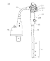
- FIG. 1 is an external view of the endoscope 10 according to the first embodiment of the present invention.
- the endoscope 10 of the present embodiment has an imaging means, an insertion unit 14 inserted into the body cavity of the subject, an operation unit 20 for operating the insertion unit 14, a processor (not shown), a light source device, and a light source device (not shown). It is provided with a connector portion 24 connected to an air supply / water supply device or the like.
- the insertion unit 14 is connected to the operation unit 20 via the folding unit 16, and the operation unit 20 is connected to the connector unit 24 via the universal cord 25.
- the universal cord 25 has flexibility, and is an electric wire that sends an electric signal from the image pickup means of the insertion portion 14 to the connector portion 24, a water channel through which water sent from the connector portion 24 passes, and an air passage through which air passes. And include.
- the operation unit 20 has a grip portion 205, a button 201 that receives an instruction such as water supply or air supply from the user, and a bending knob 21 that operates the bending of the active bending portion 9, which will be described later.
- the grip portion 205 has a substantially cylindrical shape, and the diameter is reduced toward the insertion portion 14.
- the grip portion 205 is provided with a channel inlet 22 for inserting a treatment tool or the like near the insertion portion 14.
- the insertion portion 14 has a small diameter cylindrical shape and is configured to be bendable.
- the insertion portion 14 has a tip portion 13, an active curved portion 9 (first curved portion), a passive curved portion 8 (second curved portion), and a flexible portion 11 in order from the tip side.
- the tip portion 13 has an image pickup unit (not shown) including an image pickup means such as a CCD (Charge Coupled Device) and a CMOS (Complementary Metal Oxide Semiconductor), a circuit board for driving the image pickup means, and an observation optical system. is doing. Further, the tip portion 13 has an irradiation unit (not shown) including an irradiation, an illumination optical system, and the like for irradiating an observation target portion in the body cavity.
- the active bending portion 9 can be actively curved. That is, the active bending portion 9 is curved in four directions according to the operation of the bending knob 21.
- the passively curved portion 8 is passively curved. That is, the passively curved portion 8 is curved in any of the four directions by contact with the subject.
- the flexible portion 11 has flexibility and can be flexed.
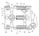
- FIG. 2 is a cross-sectional view of the active bending portion 9 and the passive bending portion 8 along the axial direction of the insertion portion 14.
- FIG. 2 shows a boundary portion between the active bending portion 9 and the passive bending portion 8.
- the active bending portion 9 has a plurality of joint cylinders 30.
- the plurality of joint cylinders 30 are connected side by side in a row.
- Each joint cylinder 30 has a substantially cylindrical shape, and is pivotally attached to adjacent joint cylinders 30 so as to be able to rotate up, down, left, and right.
- each joint cylinder 30 is provided with a pair of bearings 31 that receive one rotation axis on one end side in the axial direction, and another rotation orthogonal to the one rotation axis on the other end side in the axial direction.
- a pair of bearings 32 that receive the shaft are provided.
- the pair of bearings 31 and the pair of bearings 32 have a substantially disk shape having a through hole in the central portion, and extend in the axial direction of the joint cylinder 30.
- the plurality of joint cylinders 30 are connected so that the pair of bearings 31 and the pair of bearings 32 are alternately positioned in the arrangement direction.
- the passive bending portion 8 has a plurality of joint cylinders 40.
- the plurality of joint cylinders 40 are connected side by side in a row.
- Each joint cylinder 40 has a substantially cylindrical shape, and is pivotally attached to adjacent joint cylinders 40 so as to be able to rotate up, down, left, and right.
- each joint cylinder 40 is provided with a pair of bearings 41 that receive one rotation axis on one end side in the axial direction, and another rotation orthogonal to the one rotation axis on the other end side in the axial direction.
- a pair of bearings 42 that receive the shaft are provided.
- the pair of bearings 41 and the pair of bearings 42 have a substantially disk shape having a through hole in the center, and are displaced in the circumferential direction with respect to the pair of bearings 31 and the pair of bearings 32, and the joint cylinder 40. It is extended in the axial direction of.
- the plurality of joint cylinders 40 are connected so that the pair of bearings 41 and the pair of bearings 42 are alternately positioned in the arrangement direction.
- each operation wire 90 for bending the active bending portion 9 is inserted inside the flexible portion 11, the active bending portion 9, and the passive bending portion 8.
- One end of each operation wire 90 is fixed to the end 13 side of the tip portion 13 of the active bending portion 9, and the other end is connected to the bending knob 21 of the operation portion 20.
- the outside of the plurality of joint cylinders 30 and the plurality of joint cylinders 40 is covered with curved rubber.
- a connecting cylinder 50 is interposed between the active bending portion 9 and the passive bending portion 8. That is, the most active bending of the joint cylinder 30 on the passive bending portion 8 side (hereinafter referred to as the joint cylinder 30A) among the plurality of joint cylinders 30 of the active bending portion 9 and the most active bending of the plurality of joint cylinders 40 of the passive bending portion 8.
- the joint cylinder 40 (hereinafter referred to as the joint cylinder 40A) on the portion 9 side is connected via the connecting cylinder 50.
- FIG. 3 is a cross-sectional view showing a connected state of the joint cylinder 30A, the connecting cylinder 50, and the joint cylinder 40A (predetermined joint cylinder).
- FIG. 3 is an enlarged view of the portion surrounded by the broken line circle in FIG.
- Wire guides 33 for holding the operation wire 90 are provided at four locations on the inner peripheral surface of the joint cylinder 30A.
- the joint cylinder 30A is formed with four through holes 34 that penetrate the joint cylinder 30A in and out in order to fix the wire guide 33.
- the through holes 34 are provided at equal intervals in the circumferential direction of the joint cylinder 30A.
- Each wire guide 33 is engaged with a through hole 34.
- the wire guide 33 includes a ring-shaped holding portion 331 and a cylindrically-shaped fitted portion 332 extending outward in the radial direction of the holding portion 331.
- the fitted portion 332 is internally fitted in the through hole 34, and the operation wire 90 is inserted into the holding portion 331.
- Two of the four wire guides 33 facing each other are provided in the vicinity of the pair of bearings 31.
- the connecting cylinder 50 has a substantially cylindrical shape, and a pair of bearings 51 pivotally attached to a pair of bearings 31 of the joint cylinder 30A are extended in the axial direction at one end on the joint cylinder 30A side.
- the pair of bearings 51 have a substantially disk shape having a through hole in the center. In the connecting cylinder 50, the farther in the circumferential direction from the pair of bearings 51, the smaller the axial dimension.
- coil members 60 for guiding the operation wire 90 are provided at four places.
- the coil members 60 are provided at equal intervals in the circumferential direction of the connecting cylinder 50.
- the coil member 60 is fixed to the inner peripheral surface of the connecting cylinder 50 by welding. That is, the welded portion 53 is interposed between the coil member 60 and the connecting cylinder 50.
- Each coil member 60 has a pipe shape in which a coil wire is tightly wound.
- Each coil member 60 extends along the axial direction of the connecting cylinder 50, and the end portion of the coil member 60 protrudes from the other end of the connecting cylinder 50 and reaches the inside of the joint cylinder 40A.
- the operation wire 90 is inserted through the coil member 60.
- a pair of bearings 52 pivotally attached to a pair of bearings 41 of the joint cylinder 40A are extended in the axial direction at the other end on the joint cylinder 40A side.
- the pair of bearings 52 have a disk shape having a through hole in the center.
- the pair of bearings 52 are provided between the adjacent coil members 60.
- FIG. 4 is a perspective view showing the appearance of the joint cylinder 40A.
- the joint cylinder 40A has a substantially cylindrical shape, and the pair of bearings 41 is provided at one end on the connecting cylinder 50 side, and is pivotally attached to the pair of bearings 52 of the connecting cylinder 50. Therefore, the joint cylinder 40A rotates around an axial center penetrating the pair of bearings 41.
- the bearing 41 is flat and includes a semicircular protrusion 412 and a semicircular base 413 having a diameter larger than that of the protrusion 412, and a through hole 411 is formed in the central portion.
- the bearing 41 is arranged slightly on the axial center side of the outer peripheral surface of the joint cylinder 40A, and a guide step 414 is formed between the base portion 413 and the outer peripheral surface of the joint cylinder 40A. The height of the guide step 414 becomes lower as it is closer to the one end of the joint cylinder 40A.
- the base portion 413 projects slightly on the axial center side of the inner peripheral surface of the joint cylinder 40A.
- a step (not shown) similar to the guide step 414 is formed between the base portion 413 and the inner peripheral surface of the joint cylinder 40A.
- each notch 43 has, for example, a semicircular shape having a diameter larger than the diameter of the coil member 60.
- the notch 43 is formed so as to be spaced apart from each other by two between the pair of bearings 41.
- each notch 43 is configured to be arranged in the vicinity of the coil member 60 of the connecting cylinder 50.
- the notch 43 is formed at a position corresponding to the coil member 60 (welded portion 53) in the circumferential direction of the joint cylinder 40A.
- the pair of bearings 42 are provided at the other end of the joint cylinder 40A.
- the bearing 42 is flat and includes a semicircular protrusion 422 and a semicircular base 423 having a diameter larger than that of the protrusion 422, and a through hole 421 is formed in the central portion.
- the bearing 42 is arranged slightly radially outward from the outer peripheral surface of the joint cylinder 40A, and a step 424 is formed between the base portion 423 and the outer peripheral surface of the joint cylinder 40A. The height of the step 424 becomes higher as it is closer to the other end of the joint cylinder 40A.
- the base 423 is arranged slightly outside the inner peripheral surface of the joint cylinder 40A.
- a step (not shown) similar to the step 424 is formed between the base 423 and the inner peripheral surface of the joint cylinder 40A.
- the bearing 52 of the connecting cylinder 50 is guided by the guide step 414 of the joint cylinder 40A, is arranged on the coaxial center with the bearing 41, and is pivotally attached rotatably. Further, when the joint cylinder 40A is connected to the adjacent joint cylinder 40, the bearing 42 of the joint cylinder 40A is rotatably pivotally attached to the bearing of the adjacent joint cylinder 40.
- the coil member 60 is fixed to the inner peripheral surface of the connecting cylinder 50 by welding. Therefore, in the coil member 60, the welded portion cannot be deformed, the freely deformable portion is limited to the end portion on the joint cylinder 40A side, and the degree of freedom of deformation of the coil member 60 is significantly inferior. Therefore, the rotation of the joint cylinder 40A pivotally attached to the connecting cylinder 50 and rotating may be hindered by interference with the coil member 60 (welded portion).
- the endoscope 10 of the first embodiment is in the vicinity of the coil member 60 of the connecting cylinder 50 in the joint cylinder 40A, and is attached to the coil member 60 in the circumferential direction of the joint cylinder 40A.
- a notch 43 is formed at the corresponding position. Therefore, it is possible to reliably prevent the joint cylinder 40A from interfering with the coil member 60 when the joint cylinder 40A rotates. Therefore, in the endoscope 10 of the first embodiment, the operation wire 90 is surely guided by the coil member 60 having a long natural length, and the bending and restoration are performed at the connecting portion of the active bending portion 9 and the passive bending portion 8. It is possible to prevent problems from occurring.
- the notch 43 has a semicircular shape has been described as an example, but the present invention is not limited to this, and may be a rectangle, for example. Further, in the above description, the case where four notches 43 are formed at one end of the joint cylinder 40A has been described as an example, but the present invention is not limited to this. The number of notches 43 may be 5 or more, and may be 3 or less. Further, in the above, the case where all four notches 43 have the same shape has been described as an example, but the present invention is not limited to this, and the shapes and sizes of the four notches 43 may be different from each other. good.
- the notch 43 is provided as an example in order to prevent interference with the coil member 60.
- it is not limited to this. Needless to say, for example, it can be applied even when the coil member 60 is formed at the connecting portion between the passive bending portion 8 and the flexible portion 11.
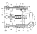
- FIG. 5 is a cross-sectional view showing a connected state of the joint cylinder 30A, the connecting cylinder 50, and the joint cylinder 40A of the endoscope 10 according to the second embodiment. Similar to the endoscope 10 of the first embodiment, the joint cylinder 40A is pivotally attached to the connecting cylinder 50, and the joint cylinder 30A is also pivotally attached to the connecting cylinder 50. Further, the coil member 60 is welded to the inner peripheral surface of the connecting cylinder 50, and the coil member 60 extends to the inside of the joint cylinder 40A.
- each notch 54 is, for example, a chamfered rectangle, and the dimension of the connecting cylinder 50 in the circumferential direction is larger than the diameter of the coil member 60.
- the cutouts 54 are formed at equal intervals in the circumferential direction of the connecting cylinder 50.
- Each notch 54 is arranged in the vicinity of the coil member 60. Specifically, the notch 54 is formed at a position corresponding to the coil member 60 in the circumferential direction of the connecting cylinder 50 in the axial direction of the connecting cylinder 50 from the other end on the joint cylinder 40A side.
- the coil member 60 is fixed to the inner peripheral surface of the connecting cylinder 50 by welding, the welded portion of the coil member 60 cannot be deformed. Therefore, the interference with the coil member 60 may hinder the rotation of the joint cylinder 40A.
- the notch 54 is formed in the connecting cylinder 50 at a position corresponding to the coil member 60 in the circumferential direction of the connecting cylinder 50. .. Therefore, in the coil member 60, the portion where the deformation is restricted by welding is reduced. Moreover, it is possible to secure a wide distance from the joint cylinder 30A side edge 541 of the notch 54 to the joint cylinder 40A. Therefore, when the joint cylinder 40A rotates, it can rotate without interfering with the welded portion of the coil member 60 and without being blocked by the coil member 60.
- the operation wire 90 is surely guided by the coil member 60 having a long natural length, and the bending and restoration are performed at the connecting portion of the active bending portion 9 and the passive bending portion 8. It is possible to prevent problems from occurring.
- the notch 54 is rectangular has been described as an example, but the present invention is not limited to this, and for example, it may have a semicircular shape.
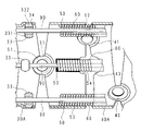
- FIG. 6 is a cross-sectional view showing a connected state of the joint cylinder 30A, the connecting cylinder 50, and the joint cylinder 40A of the endoscope 10 according to the third embodiment. Similar to the endoscope 10 of the first embodiment, the joint cylinder 40A is pivotally attached to the connecting cylinder 50, and the joint cylinder 30A is also pivotally attached to the connecting cylinder 50. Further, the coil member 60 is welded to the inner peripheral surface of the connecting cylinder 50, and the coil member 60 extends to the inside of the joint cylinder 40A.
- each notch 54 is, for example, a rectangle.
- the notch 54 has already been described in the second embodiment, and detailed description thereof will be omitted.
- each notch 43 has, for example, a semicircular shape.
- the notch 43 has already been described in the first embodiment, and detailed description thereof will be omitted.
- the coil member 60 is fixed to the inner peripheral surface of the connecting cylinder 50 by welding, the welded portion of the coil member 60 cannot be deformed. Therefore, the rotation of the joint cylinder 40A may be hindered by the interference with the welded portion of the coil member 60.
- the notch 54 is formed in the connecting cylinder 50 at a position corresponding to the coil member 60 in the circumferential direction of the connecting cylinder 50. .. Further, in the joint cylinder 40A, a notch 43 is formed at a position corresponding to the coil member 60 in the circumferential direction.
- the joint cylinder 40A can rotate without interfering with the welded portion of the coil member 60 and without being blocked by the coil member 60. Therefore, in the endoscope 10 of the third embodiment, the operation wire 90 is surely guided by the coil member 60 having a long natural length, and the bending and restoration are performed at the connecting portion of the active bending portion 9 and the passive bending portion 8. It is possible to prevent problems from occurring.
- FIG. 7 is a cross-sectional view showing a connected state of the joint cylinder 30A, the connecting cylinder 50, and the joint cylinder 40A of the endoscope 10 according to the fourth embodiment
- FIG. 8 is a cross-sectional view taken along the line VIII-VIII of FIG. Is. Similar to the endoscope 10 of the first embodiment, the joint cylinder 40A is pivotally attached to the connecting cylinder 50, and the joint cylinder 30A is also pivotally attached to the connecting cylinder 50.
- the endoscope 10 of the fourth embodiment includes a fixing annulus 55 for fixing the coil member 60.
- the fixing ring 55 has a cylindrical shape, and the axial dimension of the fixing ring 55 is smaller than the axial dimension of the connecting cylinder 50. Further, the outer diameter of the fixing ring 55 is slightly smaller than the inner diameter of the connecting cylinder 50, and is fitted inside the connecting cylinder 50.
- the fixing annulus 55 is screwed to the connecting cylinder 50 by a screw 56.
- the coil member 60 is provided with coil members 60 at four locations on the inner peripheral surface of the fixing ring 55.
- the coil members 60 are provided at equal intervals in the circumferential direction of the fixing ring 55.
- the coil member 60 is welded to the inner peripheral surface of the fixing annulus 55. That is, as shown in FIG. 8, a welded portion 53 is interposed between the coil member 60 and the fixing ring 55, and the outer peripheral surface of the fixing ring 55 is covered with the connecting cylinder 50.
- the operation wire 90 is inserted through the coil member 60.
- each notch 43 has, for example, a semicircular shape.
- the notch 43 has already been described in the first embodiment, and detailed description thereof will be omitted.
- the coil member 60 is fixed to the inner peripheral surface of the fixing ring 55 by welding, the welded portion of the coil member 60 cannot be deformed. Therefore, the rotation of the joint cylinder 40A may be hindered by the interference with the welded portion of the coil member 60.
- a notch 43 is formed at a position corresponding to the coil member 60 in the circumferential direction in the joint cylinder 40A. Therefore, the joint cylinder 40A can rotate without interfering with the welded portion of the coil member 60 and without being blocked by the coil member 60. Therefore, in the endoscope 10 of the fourth embodiment, the operation wire 90 is surely guided by the coil member 60 having a long natural length, and the bending and restoration are performed at the connecting portion of the active bending portion 9 and the passive bending portion 8. It is possible to prevent problems from occurring.
- FIG. 9 is a cross-sectional view showing a connected state of the joint cylinder 30A, the connecting cylinder 50, and the joint cylinder 40A of the endoscope 10 according to the fifth embodiment. Similar to the endoscope 10 of the first embodiment, the joint cylinder 40A is pivotally attached to the connecting cylinder 50, and the joint cylinder 30A is also pivotally attached to the connecting cylinder 50. Further, as in the fourth embodiment, the fixing ring 55 is provided, and the coil member 60 is welded to the inner peripheral surface of the fixing ring 55.
- each notch 54 is, for example, a rectangle.
- the notch 54 has already been described in the second embodiment, and detailed description thereof will be omitted.
- each notch 43 has, for example, a semicircular shape.
- the notch 43 has already been described in the first embodiment, and detailed description thereof will be omitted.
- the coil member 60 is welded to the inner peripheral surface of the fixing ring 55, the welded portion of the coil member 60 cannot be deformed. Therefore, the rotation of the joint cylinder 40A may be hindered by the interference with the welded portion of the coil member 60.
- the notch 54 is formed in the connecting cylinder 50, and the notch 43 is formed in the joint cylinder 40A. Therefore, the joint cylinder 40A can rotate without interfering with the welded portion of the coil member 60 and without being blocked by the coil member 60. Therefore, in the endoscope 10 of the fifth embodiment, the operation wire 90 is surely guided by the coil member 60 having a long natural length, and the bending and restoration are performed at the connecting portion of the active bending portion 9 and the passive bending portion 8. It is possible to prevent problems from occurring.
Landscapes
- Health & Medical Sciences (AREA)
- Life Sciences & Earth Sciences (AREA)
- Surgery (AREA)
- Physics & Mathematics (AREA)
- Optics & Photonics (AREA)
- Medical Informatics (AREA)
- Heart & Thoracic Surgery (AREA)
- Biophysics (AREA)
- Nuclear Medicine, Radiotherapy & Molecular Imaging (AREA)
- Pathology (AREA)
- Radiology & Medical Imaging (AREA)
- Veterinary Medicine (AREA)
- Engineering & Computer Science (AREA)
- Biomedical Technology (AREA)
- Public Health (AREA)
- General Health & Medical Sciences (AREA)
- Molecular Biology (AREA)
- Animal Behavior & Ethology (AREA)
- Rehabilitation Therapy (AREA)
- Astronomy & Astrophysics (AREA)
- General Physics & Mathematics (AREA)
- Endoscopes (AREA)
- Instruments For Viewing The Inside Of Hollow Bodies (AREA)
Abstract
The present invention prevents a malfunction in bending of a connection part between an active bending part and a passive bending part. An endoscope in which an active bending part and a passive bending part which are bendable are positioned in order from the distal end, the endoscope comprising a connecting cylinder (50) for connecting the active bending part and the passive bending part, wherein the active bending part and the passive bending part each include a plurality of joint cylinders (30, 40), a coil member (60) in which an operating wire (90) for bending operation of the active bending part is inserted is fixed to the connecting cylinder (50), and a notch (43) for increasing the rotational degree of freedom of a joint cylinder (40A) of the passive bending part which rotates and is connected to the connecting cylinder (50) is formed in the vicinity of the coil member (60).
Description
本発明は、湾曲可能である第1湾曲部及び第2湾曲部を備える内視鏡に関する。
本出願は、2020年9月25日出願の日本出願第2020-160963号に基づく優先権を主張し、前記これらの日本出願に記載された全ての記載内容を援用するものである。 The present invention relates to an endoscope including a first curved portion and a second curved portion that can be curved.
This application claims priority based on Japanese Application No. 2020-160963 filed on September 25, 2020, and incorporates all the contents described in these Japanese applications.
従来、体腔内に挿入される挿入部が、先端側から能動湾曲部(第1湾曲部)及び受動湾曲部(第2湾曲部)を順次有する内視鏡が広く普及している。
Conventionally, an endoscope in which an insertion portion inserted into a body cavity has an active bending portion (first bending portion) and a passive bending portion (second bending portion) sequentially from the tip side has become widespread.
例えば、特許文献1には、前記能動湾曲部から前記受動湾曲部に向かうことにつれて、湾曲時の曲率値が小さくなるようにすることによって、前記挿入部が緩やかな曲率変化をなすように構成された内視鏡が開示されている。
For example, in Patent Document 1, the insertion portion is configured to make a gradual change in curvature by reducing the curvature value at the time of bending toward the passive bending portion from the active bending portion. The endoscope is disclosed.
また、特許文献2には、ユーザが操作部を操作することによって、前記能動湾曲部及び前記受動湾曲部を夫々4方向に湾曲操作できる内視鏡が開示されている。
Further, Patent Document 2 discloses an endoscope capable of bending the active bending portion and the passive bending portion in four directions by operating the operation portion.
前記能動湾曲部及び前記受動湾曲部は夫々複数の関節円筒を含み、連結円筒を介して連結されている。また、前記能動湾曲部を湾曲操作するためのワイヤが挿通するコイル部材が例えば溶接によって前記連結円筒に固定されている。コイル部材は変形性及び復元性に優れているので、前記能動湾曲部及び前記受動湾曲部の連結部における湾曲及び復元を阻害しない。
The active bending portion and the passive bending portion each include a plurality of joint cylinders and are connected via a connecting cylinder. Further, a coil member through which a wire for bending the active bending portion is inserted is fixed to the connecting cylinder by welding, for example. Since the coil member is excellent in deformability and resilience, it does not hinder bending and restoration at the connecting portion between the active bending portion and the passive bending portion.
一方、上述の如く、前記コイル部材が溶接固定されている場合は、溶接部分では前記コイル部材の変形が制限されるので、前記能動湾曲部又は前記受動湾曲部の関節円筒が前記コイル部材と干渉する場合は、前記能動湾曲部又は前記受動湾曲部の連結部における湾曲及び復元の妨げになり得る。
しかし、特許文献1及び特許文献2の内視鏡では、このような問題に対して工夫しておらず、解決することができない。 On the other hand, as described above, when the coil member is welded and fixed, the deformation of the coil member is restricted at the welded portion, so that the joint cylinder of the active bending portion or the passive bending portion interferes with the coil member. If this is the case, it may interfere with bending and restoration at the active bending portion or the connecting portion of the passive bending portion.
However, the endoscopes of Patent Document 1 and Patent Document 2 have not devised such a problem and cannot solve it.
本発明は、斯かる事情に鑑みてなされたものであり、その目的とするところは、コイル部材が固定され、コイル部材の変形が制限されている場合であっても、能動湾曲部及び受動湾曲部の連結部における湾曲に不具合が生じることを未然に防止できる内視鏡を提供することにある。
The present invention has been made in view of such circumstances, and an object thereof is an active bending portion and a passive bending even when the coil member is fixed and the deformation of the coil member is restricted. It is an object of the present invention to provide an endoscope capable of preventing a defect in bending at a connecting portion of the portions.
本発明に係る内視鏡は、湾曲可能である第1湾曲部及び第2湾曲部が先端から順次配置され、前記第1湾曲部及び前記第2湾曲部を連結させる連結円筒を備える内視鏡において、前記第1湾曲部及び前記第2湾曲部は夫々複数の関節円筒を含み、前記連結円筒には、前記第1湾曲部を湾曲操作するためのワイヤが挿通されるコイル部材が固定されており、前記連結円筒に連結されて回動する前記第2湾曲部の所定関節円筒の回動自由度を高める切り欠きが前記コイル部材の近傍に形成されている。
The endoscope according to the present invention is an endoscope in which a bendable first curved portion and a second curved portion are sequentially arranged from the tip, and the endoscope includes a connecting cylinder for connecting the first curved portion and the second curved portion. The first curved portion and the second curved portion each include a plurality of joint cylinders, and a coil member through which a wire for bending the first curved portion is inserted is fixed to the connecting cylinder. A notch is formed in the vicinity of the coil member to increase the degree of freedom of rotation of the predetermined joint cylinder of the second curved portion that is connected to the connecting cylinder and rotates.
本発明にあっては、前記切り欠きが、前記所定関節円筒又は前記連結円筒における前記コイル部材の近傍に形成されており、斯かる切り欠きによって、前記コイル部材と前記所定関節円筒との干渉が解消され、又はコイル部材に前記所定関節円筒の回動が阻止されることを抑制でき、前記所定関節円筒の回動自由度が高まる。
In the present invention, the notch is formed in the vicinity of the coil member in the predetermined joint cylinder or the connecting cylinder, and the notch causes interference between the coil member and the predetermined joint cylinder. It can be eliminated or the coil member can prevent the predetermined joint cylinder from being prevented from rotating, and the degree of freedom of rotation of the predetermined joint cylinder is increased.
本発明によれば、コイル部材が固定され、コイル部材の変形が制限されている場合であっても、能動湾曲部及び受動湾曲部の連結部における湾曲に不具合が生じることを未然に防止できる。
According to the present invention, even when the coil member is fixed and the deformation of the coil member is restricted, it is possible to prevent a defect in bending at the connecting portion between the active bending portion and the passive bending portion.
以下に、本発明の実施の形態に係る内視鏡について、図面に基づいて詳述する。
The endoscope according to the embodiment of the present invention will be described in detail below with reference to the drawings.
(実施の形態1)
図1は、本発明の実施の形態1に係る内視鏡10の外観図である。本実施の形態の内視鏡10は、撮像手段を有し、被検者の体腔内に挿入される挿入部14と、挿入部14を操作する操作部20と、図示しないプロセッサ、光源装置及び送気送水装置等に接続されるコネクタ部24とを備える。
挿入部14は、折止部16を介して操作部20に接続されており、操作部20はユニバーサルコード25を介してコネクタ部24に接続されている。 (Embodiment 1)
FIG. 1 is an external view of theendoscope 10 according to the first embodiment of the present invention. The endoscope 10 of the present embodiment has an imaging means, an insertion unit 14 inserted into the body cavity of the subject, an operation unit 20 for operating the insertion unit 14, a processor (not shown), a light source device, and a light source device (not shown). It is provided with a connector portion 24 connected to an air supply / water supply device or the like.
Theinsertion unit 14 is connected to the operation unit 20 via the folding unit 16, and the operation unit 20 is connected to the connector unit 24 via the universal cord 25.
図1は、本発明の実施の形態1に係る内視鏡10の外観図である。本実施の形態の内視鏡10は、撮像手段を有し、被検者の体腔内に挿入される挿入部14と、挿入部14を操作する操作部20と、図示しないプロセッサ、光源装置及び送気送水装置等に接続されるコネクタ部24とを備える。
挿入部14は、折止部16を介して操作部20に接続されており、操作部20はユニバーサルコード25を介してコネクタ部24に接続されている。 (Embodiment 1)
FIG. 1 is an external view of the
The
ユニバーサルコード25は、柔軟性を有しており、挿入部14の前記撮像手段からの電気信号をコネクタ部24に送る電気線と、コネクタ部24から送られる水が通る水路及び空気が通る気路とを含む。
The universal cord 25 has flexibility, and is an electric wire that sends an electric signal from the image pickup means of the insertion portion 14 to the connector portion 24, a water channel through which water sent from the connector portion 24 passes, and an air passage through which air passes. And include.
操作部20は、把持部205と、給水又は給気等の指示をユーザから受け付けるボタン201と、後述する能動湾曲部9の湾曲を操作する湾曲ノブ21とを有している。
The operation unit 20 has a grip portion 205, a button 201 that receives an instruction such as water supply or air supply from the user, and a bending knob 21 that operates the bending of the active bending portion 9, which will be described later.
把持部205は略円筒形状を有しており、挿入部14に向かって縮径している。把持部205には挿入部14側寄りに、処置具等を挿入するためのチャンネル入口22が設けられている。
The grip portion 205 has a substantially cylindrical shape, and the diameter is reduced toward the insertion portion 14. The grip portion 205 is provided with a channel inlet 22 for inserting a treatment tool or the like near the insertion portion 14.
挿入部14は、細径の円筒形状を有しており、湾曲可能に構成されている。挿入部14は先端側から順に先端部13、能動湾曲部9(第1湾曲部)、受動湾曲部8(第2湾曲部)及び可撓部11を有している。
The insertion portion 14 has a small diameter cylindrical shape and is configured to be bendable. The insertion portion 14 has a tip portion 13, an active curved portion 9 (first curved portion), a passive curved portion 8 (second curved portion), and a flexible portion 11 in order from the tip side.
先端部13は、CCD(Charge Coupled Device)、CMOS(Complementary Metal Oxide Semiconductor)等の撮像手段、該撮像手段を駆動するための回路基板、観察光学系等を含む撮像ユニット(図示せず)を有している。また、先端部13は、体腔内の観察対象部位を照射する照射、照明光学系等を含む照明ユニット(図示せず)を有している。
The tip portion 13 has an image pickup unit (not shown) including an image pickup means such as a CCD (Charge Coupled Device) and a CMOS (Complementary Metal Oxide Semiconductor), a circuit board for driving the image pickup means, and an observation optical system. is doing. Further, the tip portion 13 has an irradiation unit (not shown) including an irradiation, an illumination optical system, and the like for irradiating an observation target portion in the body cavity.
能動湾曲部9は能動的に湾曲可能である。即ち、能動湾曲部9は湾曲ノブ21の操作に応じて4方向に湾曲される。一方、受動湾曲部8は受動的に湾曲される。即ち、受動湾曲部8は被検体との接触によって4方向の何れかに湾曲する。可撓部11は可撓性を有し、撓むことができる。
The active bending portion 9 can be actively curved. That is, the active bending portion 9 is curved in four directions according to the operation of the bending knob 21. On the other hand, the passively curved portion 8 is passively curved. That is, the passively curved portion 8 is curved in any of the four directions by contact with the subject. The flexible portion 11 has flexibility and can be flexed.
図2は、挿入部14の軸方向に沿う、能動湾曲部9及び受動湾曲部8の断面図である。特に、図2は、能動湾曲部9と受動湾曲部8との境界部分を示している。
FIG. 2 is a cross-sectional view of the active bending portion 9 and the passive bending portion 8 along the axial direction of the insertion portion 14. In particular, FIG. 2 shows a boundary portion between the active bending portion 9 and the passive bending portion 8.
能動湾曲部9は、複数の関節円筒30を有している。複数の関節円筒30は一列に並んで連結されている。各関節円筒30は略円筒形状を有しており、上下左右へ回動できるように隣り合う関節円筒30と枢着されている。
The active bending portion 9 has a plurality of joint cylinders 30. The plurality of joint cylinders 30 are connected side by side in a row. Each joint cylinder 30 has a substantially cylindrical shape, and is pivotally attached to adjacent joint cylinders 30 so as to be able to rotate up, down, left, and right.
また、各関節円筒30は軸方向の一端側に、一の回動軸を受ける一対の軸受31が設けられ、軸方向の他端側に、前記一の回動軸と直交する他の回動軸を受ける一対の軸受32が設けられている。前記一対の軸受31及び前記一対の軸受32は、中央部に貫通孔を有する略円板形状をなし、関節円筒30の軸方向に延設されている。
複数の関節円筒30は、並び方向において、前記一対の軸受31及び前記一対の軸受32が交互に位置されるように連結されている。 Further, eachjoint cylinder 30 is provided with a pair of bearings 31 that receive one rotation axis on one end side in the axial direction, and another rotation orthogonal to the one rotation axis on the other end side in the axial direction. A pair of bearings 32 that receive the shaft are provided. The pair of bearings 31 and the pair of bearings 32 have a substantially disk shape having a through hole in the central portion, and extend in the axial direction of the joint cylinder 30.
The plurality ofjoint cylinders 30 are connected so that the pair of bearings 31 and the pair of bearings 32 are alternately positioned in the arrangement direction.
複数の関節円筒30は、並び方向において、前記一対の軸受31及び前記一対の軸受32が交互に位置されるように連結されている。 Further, each
The plurality of
受動湾曲部8は、複数の関節円筒40を有している。複数の関節円筒40は一列に並んで連結されている。各関節円筒40は略円筒形状を有しており、上下左右へ回動できるように隣り合う関節円筒40と枢着されている。
The passive bending portion 8 has a plurality of joint cylinders 40. The plurality of joint cylinders 40 are connected side by side in a row. Each joint cylinder 40 has a substantially cylindrical shape, and is pivotally attached to adjacent joint cylinders 40 so as to be able to rotate up, down, left, and right.
また、各関節円筒40は軸方向の一端側に、一の回動軸を受ける一対の軸受41が設けられ、軸方向の他端側に、前記一の回動軸と直交する他の回動軸を受ける一対の軸受42が設けられている。前記一対の軸受41及び前記一対の軸受42は、中央部に貫通孔を有する略円板形状をなし、一対の軸受31及び前記一対の軸受32に対して周方向にずれており、関節円筒40の軸方向に延設されている。複数の関節円筒40は、並び方向において、一対の軸受41及び一対の軸受42が交互に位置されるように連結されている。
Further, each joint cylinder 40 is provided with a pair of bearings 41 that receive one rotation axis on one end side in the axial direction, and another rotation orthogonal to the one rotation axis on the other end side in the axial direction. A pair of bearings 42 that receive the shaft are provided. The pair of bearings 41 and the pair of bearings 42 have a substantially disk shape having a through hole in the center, and are displaced in the circumferential direction with respect to the pair of bearings 31 and the pair of bearings 32, and the joint cylinder 40. It is extended in the axial direction of. The plurality of joint cylinders 40 are connected so that the pair of bearings 41 and the pair of bearings 42 are alternately positioned in the arrangement direction.
可撓部11、能動湾曲部9及び受動湾曲部8の内側には、能動湾曲部9を湾曲操作する操作ワイヤ90が4本挿通されている。各操作ワイヤ90の一端は、能動湾曲部9の先端部13側端部に固定され、他端は、操作部20の湾曲ノブ21に接続されている。複数の関節円筒30及び複数の関節円筒40の外側は、湾曲ゴムによって被覆されている。
Four operation wires 90 for bending the active bending portion 9 are inserted inside the flexible portion 11, the active bending portion 9, and the passive bending portion 8. One end of each operation wire 90 is fixed to the end 13 side of the tip portion 13 of the active bending portion 9, and the other end is connected to the bending knob 21 of the operation portion 20. The outside of the plurality of joint cylinders 30 and the plurality of joint cylinders 40 is covered with curved rubber.
能動湾曲部9及び受動湾曲部8の間には連結円筒50が介在している。即ち、能動湾曲部9の複数の関節円筒30のうち最も受動湾曲部8側の関節円筒30(以下、関節円筒30Aと称する)と、受動湾曲部8の複数の関節円筒40のうち最も能動湾曲部9側の関節円筒40(以下、関節円筒40Aと称する)とが連結円筒50を介して連結されている。
A connecting cylinder 50 is interposed between the active bending portion 9 and the passive bending portion 8. That is, the most active bending of the joint cylinder 30 on the passive bending portion 8 side (hereinafter referred to as the joint cylinder 30A) among the plurality of joint cylinders 30 of the active bending portion 9 and the most active bending of the plurality of joint cylinders 40 of the passive bending portion 8. The joint cylinder 40 (hereinafter referred to as the joint cylinder 40A) on the portion 9 side is connected via the connecting cylinder 50.
図3は、関節円筒30A、連結円筒50及び関節円筒40A(所定関節円筒)の連結状態を示す断面図である。図3は、図2にて破線の円で囲まれた部分を拡大して示している。
FIG. 3 is a cross-sectional view showing a connected state of the joint cylinder 30A, the connecting cylinder 50, and the joint cylinder 40A (predetermined joint cylinder). FIG. 3 is an enlarged view of the portion surrounded by the broken line circle in FIG.
関節円筒30Aの内周面には、操作ワイヤ90を保持するワイヤガイド33が4箇所に設けられている。関節円筒30Aには、ワイヤガイド33を固定するために、関節円筒30Aを内外に貫通する貫通孔34が4箇所に形成されている。貫通孔34は、関節円筒30Aの周方向に、等間隔にて設けられている。各ワイヤガイド33は貫通孔34に係合されている。
Wire guides 33 for holding the operation wire 90 are provided at four locations on the inner peripheral surface of the joint cylinder 30A. The joint cylinder 30A is formed with four through holes 34 that penetrate the joint cylinder 30A in and out in order to fix the wire guide 33. The through holes 34 are provided at equal intervals in the circumferential direction of the joint cylinder 30A. Each wire guide 33 is engaged with a through hole 34.
ワイヤガイド33は、リング状の保持部331と、保持部331の径方向に外方へ延出された円柱形状の被嵌合部332とを含む。被嵌合部332が貫通孔34に内嵌され、保持部331内に操作ワイヤ90が挿通される。
4つのワイヤガイド33のうち対向する2つのワイヤガイド33は、一対の軸受31の近傍に設けられている。 Thewire guide 33 includes a ring-shaped holding portion 331 and a cylindrically-shaped fitted portion 332 extending outward in the radial direction of the holding portion 331. The fitted portion 332 is internally fitted in the through hole 34, and the operation wire 90 is inserted into the holding portion 331.
Two of the four wire guides 33 facing each other are provided in the vicinity of the pair ofbearings 31.
4つのワイヤガイド33のうち対向する2つのワイヤガイド33は、一対の軸受31の近傍に設けられている。 The
Two of the four wire guides 33 facing each other are provided in the vicinity of the pair of
連結円筒50は、略円筒形状をなしており、関節円筒30A側の一端に、関節円筒30Aの一対の軸受31と枢着する一対の軸受51が軸方向に延設されている。一対の軸受51は中央部に貫通孔を有する略円板形状をなしている。連結円筒50では、一対の軸受51から周方向で遠い程、軸方向の寸法が小さくなる。
The connecting cylinder 50 has a substantially cylindrical shape, and a pair of bearings 51 pivotally attached to a pair of bearings 31 of the joint cylinder 30A are extended in the axial direction at one end on the joint cylinder 30A side. The pair of bearings 51 have a substantially disk shape having a through hole in the center. In the connecting cylinder 50, the farther in the circumferential direction from the pair of bearings 51, the smaller the axial dimension.
また、連結円筒50の内周面には、操作ワイヤ90を案内するコイル部材60が4箇所に設けられている。コイル部材60は、連結円筒50の周方向に、等間隔にて設けられている。例えば、コイル部材60は連結円筒50の内周面に溶接によって固定されている。即ち、コイル部材60と連結円筒50との間には溶接部53が介在する。
Further, on the inner peripheral surface of the connecting cylinder 50, coil members 60 for guiding the operation wire 90 are provided at four places. The coil members 60 are provided at equal intervals in the circumferential direction of the connecting cylinder 50. For example, the coil member 60 is fixed to the inner peripheral surface of the connecting cylinder 50 by welding. That is, the welded portion 53 is interposed between the coil member 60 and the connecting cylinder 50.
各コイル部材60は、コイル線材を密着巻きしたパイプ状をなしている。各コイル部材60は連結円筒50の軸方向に沿って延び、コイル部材60の端部は、連結円筒50の他端からはみ出て、関節円筒40Aの内側まで至る。操作ワイヤ90がコイル部材60に挿通されている。
Each coil member 60 has a pipe shape in which a coil wire is tightly wound. Each coil member 60 extends along the axial direction of the connecting cylinder 50, and the end portion of the coil member 60 protrudes from the other end of the connecting cylinder 50 and reaches the inside of the joint cylinder 40A. The operation wire 90 is inserted through the coil member 60.
更に、連結円筒50では、関節円筒40A側の他端に、関節円筒40Aの一対の軸受41と枢着する一対の軸受52が軸方向に延設されている。一対の軸受52は中央部に貫通孔を有する円板形状をなしている。一対の軸受52は、隣り合うコイル部材60の間に設けられている。
Further, in the connecting cylinder 50, a pair of bearings 52 pivotally attached to a pair of bearings 41 of the joint cylinder 40A are extended in the axial direction at the other end on the joint cylinder 40A side. The pair of bearings 52 have a disk shape having a through hole in the center. The pair of bearings 52 are provided between the adjacent coil members 60.
図4は、関節円筒40Aの外見を示す斜視図である。
関節円筒40Aは、略円筒形状をなしており、連結円筒50側の一端に、前記一対の軸受41が設けられており、連結円筒50の一対の軸受52と枢着している。よって、関節円筒40Aは一対の軸受41を貫く軸心の周りを回動する。 FIG. 4 is a perspective view showing the appearance of thejoint cylinder 40A.
Thejoint cylinder 40A has a substantially cylindrical shape, and the pair of bearings 41 is provided at one end on the connecting cylinder 50 side, and is pivotally attached to the pair of bearings 52 of the connecting cylinder 50. Therefore, the joint cylinder 40A rotates around an axial center penetrating the pair of bearings 41.
関節円筒40Aは、略円筒形状をなしており、連結円筒50側の一端に、前記一対の軸受41が設けられており、連結円筒50の一対の軸受52と枢着している。よって、関節円筒40Aは一対の軸受41を貫く軸心の周りを回動する。 FIG. 4 is a perspective view showing the appearance of the
The
軸受41は扁平であり、半円形状の突出部412と、突出部412よりも大径の半円形状の基部413とを含み、中央部には貫通孔411が形成されている。軸受41は、関節円筒40Aの外周面よりも少し軸心側に配置されており、基部413と、関節円筒40Aの外周面との間には案内段差414が形成されている。案内段差414の高さは、関節円筒40Aの前記一端に近い程低くなる。
The bearing 41 is flat and includes a semicircular protrusion 412 and a semicircular base 413 having a diameter larger than that of the protrusion 412, and a through hole 411 is formed in the central portion. The bearing 41 is arranged slightly on the axial center side of the outer peripheral surface of the joint cylinder 40A, and a guide step 414 is formed between the base portion 413 and the outer peripheral surface of the joint cylinder 40A. The height of the guide step 414 becomes lower as it is closer to the one end of the joint cylinder 40A.
上述の如く、軸受41が関節円筒40Aの外周面よりも少し軸心側に配置されているので、基部413は関節円筒40Aの内周面よりも少し軸心側に突出している。これにより、基部413と関節円筒40Aの内周面との間にも案内段差414と同様の段差(図示せず)が形成されている。
As described above, since the bearing 41 is arranged slightly on the axial center side of the outer peripheral surface of the joint cylinder 40A, the base portion 413 projects slightly on the axial center side of the inner peripheral surface of the joint cylinder 40A. As a result, a step (not shown) similar to the guide step 414 is formed between the base portion 413 and the inner peripheral surface of the joint cylinder 40A.
また、関節円筒40Aの前記一端には、関節円筒40Aの回動自由度を高める、4つの切り欠き43(第1切り欠き)が形成されている。各切り欠き43は、例えばコイル部材60の径よりも大きい径の半円形状を有する。
Further, at one end of the joint cylinder 40A, four notches 43 (first notch) are formed to increase the degree of freedom of rotation of the joint cylinder 40A. Each notch 43 has, for example, a semicircular shape having a diameter larger than the diameter of the coil member 60.
切り欠き43は、一対の軸受41の間に2つずつ間隔を開けて形成されている。関節円筒40Aが連結円筒50と連結された場合、各切り欠き43が連結円筒50のコイル部材60の近傍に配置されるように、構成されている。詳しくは、切り欠き43は関節円筒40Aの周方向においてコイル部材60(溶接部53)に対応する位置に形成されている。
The notch 43 is formed so as to be spaced apart from each other by two between the pair of bearings 41. When the joint cylinder 40A is connected to the connecting cylinder 50, each notch 43 is configured to be arranged in the vicinity of the coil member 60 of the connecting cylinder 50. Specifically, the notch 43 is formed at a position corresponding to the coil member 60 (welded portion 53) in the circumferential direction of the joint cylinder 40A.
更に、上述の如く、関節円筒40Aの前記他端には前記一対の軸受42が設けられている。軸受42は扁平であり、半円形状の突出部422と、突出部422よりも大径の半円形状の基部423とを含み、中央部には貫通孔421が形成されている。軸受42は、関節円筒40Aの外周面よりも少し径方向へ外側に配置されており、基部423と、関節円筒40Aの外周面との間には段差424が形成されている。段差424の高さは、関節円筒40Aの前記他端に近い程高くなる。
Further, as described above, the pair of bearings 42 are provided at the other end of the joint cylinder 40A. The bearing 42 is flat and includes a semicircular protrusion 422 and a semicircular base 423 having a diameter larger than that of the protrusion 422, and a through hole 421 is formed in the central portion. The bearing 42 is arranged slightly radially outward from the outer peripheral surface of the joint cylinder 40A, and a step 424 is formed between the base portion 423 and the outer peripheral surface of the joint cylinder 40A. The height of the step 424 becomes higher as it is closer to the other end of the joint cylinder 40A.
このように、軸受42が関節円筒40Aの外周面よりも少し径方向へ外側に配置されているので、基部423は関節円筒40Aの内周面よりも少し外側に配置されている。これにより、基部423と関節円筒40Aの内周面との間にも段差424と同様の段差(図示せず)が形成されている。
As described above, since the bearing 42 is arranged slightly radially outside the outer peripheral surface of the joint cylinder 40A, the base 423 is arranged slightly outside the inner peripheral surface of the joint cylinder 40A. As a result, a step (not shown) similar to the step 424 is formed between the base 423 and the inner peripheral surface of the joint cylinder 40A.
関節円筒40Aが連結円筒50と連結される際、連結円筒50の軸受52が、関節円筒40Aの案内段差414に案内されて軸受41と同軸心上に配置されて回動可能に枢着する。また、関節円筒40Aが隣り合う関節円筒40と連結される際、関節円筒40Aの軸受42が隣り合う関節円筒40の軸受と回動可能に枢着する。
When the joint cylinder 40A is connected to the connecting cylinder 50, the bearing 52 of the connecting cylinder 50 is guided by the guide step 414 of the joint cylinder 40A, is arranged on the coaxial center with the bearing 41, and is pivotally attached rotatably. Further, when the joint cylinder 40A is connected to the adjacent joint cylinder 40, the bearing 42 of the joint cylinder 40A is rotatably pivotally attached to the bearing of the adjacent joint cylinder 40.
上述の如く、コイル部材60が連結円筒50の内周面に溶接によって固定されている。よって、コイル部材60においては、溶接部分は変形ができず、自由変形可能な部分は関節円筒40A側の端部に制限され、コイル部材60の変形自由度が大きく劣る。従って、連結円筒50に枢着されて回動する関節円筒40Aは、コイル部材60(溶接部分)との干渉により、その回動が阻害される恐れがある。
As described above, the coil member 60 is fixed to the inner peripheral surface of the connecting cylinder 50 by welding. Therefore, in the coil member 60, the welded portion cannot be deformed, the freely deformable portion is limited to the end portion on the joint cylinder 40A side, and the degree of freedom of deformation of the coil member 60 is significantly inferior. Therefore, the rotation of the joint cylinder 40A pivotally attached to the connecting cylinder 50 and rotating may be hindered by interference with the coil member 60 (welded portion).
これに対して、実施の形態1の内視鏡10は、上述の如く、関節円筒40Aにおいて、連結円筒50のコイル部材60の近傍であって、関節円筒40Aの周方向にてコイル部材60に対応する位置に、切り欠き43が形成されている。従って、関節円筒40Aが回動する際に、関節円筒40Aがコイル部材60と干渉することを確実に防ぐことができる。
よって、実施の形態1の内視鏡10では、自然長が長いコイル部材60を用いて確実に操作ワイヤ90を案内しつつ、能動湾曲部9及び受動湾曲部8の連結部にて湾曲及び復元に不具合が生じることを未然に抑制できる。 On the other hand, as described above, theendoscope 10 of the first embodiment is in the vicinity of the coil member 60 of the connecting cylinder 50 in the joint cylinder 40A, and is attached to the coil member 60 in the circumferential direction of the joint cylinder 40A. A notch 43 is formed at the corresponding position. Therefore, it is possible to reliably prevent the joint cylinder 40A from interfering with the coil member 60 when the joint cylinder 40A rotates.
Therefore, in theendoscope 10 of the first embodiment, the operation wire 90 is surely guided by the coil member 60 having a long natural length, and the bending and restoration are performed at the connecting portion of the active bending portion 9 and the passive bending portion 8. It is possible to prevent problems from occurring.
よって、実施の形態1の内視鏡10では、自然長が長いコイル部材60を用いて確実に操作ワイヤ90を案内しつつ、能動湾曲部9及び受動湾曲部8の連結部にて湾曲及び復元に不具合が生じることを未然に抑制できる。 On the other hand, as described above, the
Therefore, in the
以上においては、切り欠き43が半円形状を有する場合を例に挙げて説明したが、これに限定されるものではなく、例えば矩形であっても良い。
また、以上においては、関節円筒40Aの前記一端に4つの切り欠き43が形成されている場合を例に挙げて説明したが、これに限定されるものではない。切り欠き43の数は5つ以上であっても良く、3つ以下であっても良い。
更に、以上においては、4つの切り欠き43が全て同じ形状である場合を例に挙げて説明したが、これに限定されるものではなく、それぞれの形状や大きさが異なるように構成しても良い。 In the above, the case where thenotch 43 has a semicircular shape has been described as an example, but the present invention is not limited to this, and may be a rectangle, for example.
Further, in the above description, the case where fournotches 43 are formed at one end of the joint cylinder 40A has been described as an example, but the present invention is not limited to this. The number of notches 43 may be 5 or more, and may be 3 or less.
Further, in the above, the case where all fournotches 43 have the same shape has been described as an example, but the present invention is not limited to this, and the shapes and sizes of the four notches 43 may be different from each other. good.
また、以上においては、関節円筒40Aの前記一端に4つの切り欠き43が形成されている場合を例に挙げて説明したが、これに限定されるものではない。切り欠き43の数は5つ以上であっても良く、3つ以下であっても良い。
更に、以上においては、4つの切り欠き43が全て同じ形状である場合を例に挙げて説明したが、これに限定されるものではなく、それぞれの形状や大きさが異なるように構成しても良い。 In the above, the case where the
Further, in the above description, the case where four
Further, in the above, the case where all four
また、以上においては、能動湾曲部9及び受動湾曲部8の連結部にコイル部材60が形成されている場合、コイル部材60との干渉を防ぐために切り欠き43を設けることを例に挙げて説明したがこれに限定されるものではない。例えば、受動湾曲部8と可撓部11との連結部にコイル部材60が形成されている場合にも適用可能であることは言うまでもない。
Further, in the above, when the coil member 60 is formed at the connecting portion of the active bending portion 9 and the passive bending portion 8, the notch 43 is provided as an example in order to prevent interference with the coil member 60. However, it is not limited to this. Needless to say, for example, it can be applied even when the coil member 60 is formed at the connecting portion between the passive bending portion 8 and the flexible portion 11.
(実施の形態2)
図5は、実施の形態2に係る内視鏡10の関節円筒30A、連結円筒50及び関節円筒40Aの連結状態を示す断面図である。実施の形態1の内視鏡10と同様、関節円筒40Aが連結円筒50に枢着されており、関節円筒30Aも連結円筒50に枢着されている。また、コイル部材60が連結円筒50の内周面に溶接されており、コイル部材60は関節円筒40Aの内側まで延びている。 (Embodiment 2)
FIG. 5 is a cross-sectional view showing a connected state of thejoint cylinder 30A, the connecting cylinder 50, and the joint cylinder 40A of the endoscope 10 according to the second embodiment. Similar to the endoscope 10 of the first embodiment, the joint cylinder 40A is pivotally attached to the connecting cylinder 50, and the joint cylinder 30A is also pivotally attached to the connecting cylinder 50. Further, the coil member 60 is welded to the inner peripheral surface of the connecting cylinder 50, and the coil member 60 extends to the inside of the joint cylinder 40A.
図5は、実施の形態2に係る内視鏡10の関節円筒30A、連結円筒50及び関節円筒40Aの連結状態を示す断面図である。実施の形態1の内視鏡10と同様、関節円筒40Aが連結円筒50に枢着されており、関節円筒30Aも連結円筒50に枢着されている。また、コイル部材60が連結円筒50の内周面に溶接されており、コイル部材60は関節円筒40Aの内側まで延びている。 (Embodiment 2)
FIG. 5 is a cross-sectional view showing a connected state of the
実施の形態2の内視鏡10では、連結円筒50において、関節円筒40A側の他端に、関節円筒40Aの回動自由度を高める、4つの切り欠き54(第2切り欠き)が形成されている。各切り欠き54は、例えば面取りされた矩形であり、連結円筒50の周方向における寸法がコイル部材60の径よりも大きい。切り欠き54は、連結円筒50の周方向に等間隔にて形成されている。
In the endoscope 10 of the second embodiment, four notches 54 (second notches) are formed at the other end of the connecting cylinder 50 on the joint cylinder 40A side to increase the degree of freedom of rotation of the joint cylinder 40A. ing. Each notch 54 is, for example, a chamfered rectangle, and the dimension of the connecting cylinder 50 in the circumferential direction is larger than the diameter of the coil member 60. The cutouts 54 are formed at equal intervals in the circumferential direction of the connecting cylinder 50.
各切り欠き54は、コイル部材60の近傍に配置されている。詳しくは、切り欠き54は連結円筒50の周方向においてコイル部材60に対応する位置に、関節円筒40A側の他端から連結円筒50の軸方向に形成されている。
Each notch 54 is arranged in the vicinity of the coil member 60. Specifically, the notch 54 is formed at a position corresponding to the coil member 60 in the circumferential direction of the connecting cylinder 50 in the axial direction of the connecting cylinder 50 from the other end on the joint cylinder 40A side.
上述の如く、コイル部材60が連結円筒50の内周面に溶接によって固定されているので、コイル部材60における溶接部分は変形ができない。従って、コイル部材60との干渉により、関節円筒40Aの回動が阻害される恐れがある。
As described above, since the coil member 60 is fixed to the inner peripheral surface of the connecting cylinder 50 by welding, the welded portion of the coil member 60 cannot be deformed. Therefore, the interference with the coil member 60 may hinder the rotation of the joint cylinder 40A.
これに対して、実施の形態2の内視鏡10は、上述の如く、連結円筒50において、連結円筒50の周方向にてコイル部材60に対応する位置に、切り欠き54が形成されている。従って、コイル部材60において、溶接により変形が制限された部分が少なくなっている。かつ、切り欠き54の関節円筒30A側縁541から、関節円筒40Aまでの間隔を広く確保することができる。よって、関節円筒40Aは、回動する際に、コイル部材60の溶接部分と干渉せず、コイル部材60に阻止されることなく、回動できる。
従って、実施の形態2の内視鏡10では、自然長が長いコイル部材60を用いて確実に操作ワイヤ90を案内しつつ、能動湾曲部9及び受動湾曲部8の連結部にて湾曲及び復元に不具合が生じることを未然に抑制できる。 On the other hand, in theendoscope 10 of the second embodiment, as described above, the notch 54 is formed in the connecting cylinder 50 at a position corresponding to the coil member 60 in the circumferential direction of the connecting cylinder 50. .. Therefore, in the coil member 60, the portion where the deformation is restricted by welding is reduced. Moreover, it is possible to secure a wide distance from the joint cylinder 30A side edge 541 of the notch 54 to the joint cylinder 40A. Therefore, when the joint cylinder 40A rotates, it can rotate without interfering with the welded portion of the coil member 60 and without being blocked by the coil member 60.
Therefore, in theendoscope 10 of the second embodiment, the operation wire 90 is surely guided by the coil member 60 having a long natural length, and the bending and restoration are performed at the connecting portion of the active bending portion 9 and the passive bending portion 8. It is possible to prevent problems from occurring.
従って、実施の形態2の内視鏡10では、自然長が長いコイル部材60を用いて確実に操作ワイヤ90を案内しつつ、能動湾曲部9及び受動湾曲部8の連結部にて湾曲及び復元に不具合が生じることを未然に抑制できる。 On the other hand, in the
Therefore, in the
以上においては、切り欠き54が矩形である場合を例に挙げて説明したが、これに限定されるものではなく、例えば半円形状を有しても良い。
In the above, the case where the notch 54 is rectangular has been described as an example, but the present invention is not limited to this, and for example, it may have a semicircular shape.
実施の形態1と同様の部分については、同一の符号を付して詳細な説明を省略する。
The same parts as those in the first embodiment are designated by the same reference numerals and detailed description thereof will be omitted.
(実施の形態3)
図6は、実施の形態3に係る内視鏡10の関節円筒30A、連結円筒50及び関節円筒40Aの連結状態を示す断面図である。実施の形態1の内視鏡10と同様、関節円筒40Aが連結円筒50に枢着されており、関節円筒30Aも連結円筒50に枢着されている。また、コイル部材60が連結円筒50の内周面に溶接されており、コイル部材60は関節円筒40Aの内側まで延びている。 (Embodiment 3)
FIG. 6 is a cross-sectional view showing a connected state of thejoint cylinder 30A, the connecting cylinder 50, and the joint cylinder 40A of the endoscope 10 according to the third embodiment. Similar to the endoscope 10 of the first embodiment, the joint cylinder 40A is pivotally attached to the connecting cylinder 50, and the joint cylinder 30A is also pivotally attached to the connecting cylinder 50. Further, the coil member 60 is welded to the inner peripheral surface of the connecting cylinder 50, and the coil member 60 extends to the inside of the joint cylinder 40A.
図6は、実施の形態3に係る内視鏡10の関節円筒30A、連結円筒50及び関節円筒40Aの連結状態を示す断面図である。実施の形態1の内視鏡10と同様、関節円筒40Aが連結円筒50に枢着されており、関節円筒30Aも連結円筒50に枢着されている。また、コイル部材60が連結円筒50の内周面に溶接されており、コイル部材60は関節円筒40Aの内側まで延びている。 (Embodiment 3)
FIG. 6 is a cross-sectional view showing a connected state of the
実施の形態3の内視鏡10では、連結円筒50において、関節円筒40A側の他端に、関節円筒40Aの回動自由度を高める、4つの切り欠き54(第2切り欠き)が形成されている。各切り欠き54は、例えば矩形である。切り欠き54については、実施の形態2で既に説明しており、詳しい説明は省略する。
In the endoscope 10 of the third embodiment, four notches 54 (second notches) are formed at the other end of the connecting cylinder 50 on the joint cylinder 40A side to increase the degree of freedom of rotation of the joint cylinder 40A. ing. Each notch 54 is, for example, a rectangle. The notch 54 has already been described in the second embodiment, and detailed description thereof will be omitted.
また、関節円筒40Aの連結円筒50側の一端には、関節円筒40Aの回動自由度を高める、4つの切り欠き43(第1切り欠き)が形成されている。各切り欠き43は、例えば半円形状を有する。切り欠き43については、実施の形態1で既に説明しており、詳しい説明は省略する。
Further, at one end of the joint cylinder 40A on the connecting cylinder 50 side, four notches 43 (first notch) are formed to increase the degree of freedom of rotation of the joint cylinder 40A. Each notch 43 has, for example, a semicircular shape. The notch 43 has already been described in the first embodiment, and detailed description thereof will be omitted.
上述の如く、コイル部材60が連結円筒50の内周面に溶接によって固定されているので、コイル部材60における溶接部分は変形ができない。従って、コイル部材60の溶接部分との干渉により、関節円筒40Aの回動が阻害される恐れがある。
As described above, since the coil member 60 is fixed to the inner peripheral surface of the connecting cylinder 50 by welding, the welded portion of the coil member 60 cannot be deformed. Therefore, the rotation of the joint cylinder 40A may be hindered by the interference with the welded portion of the coil member 60.
これに対して、実施の形態3の内視鏡10は、上述の如く、連結円筒50において、連結円筒50の周方向にてコイル部材60に対応する位置に、切り欠き54が形成されている。また、関節円筒40Aにおいて、周方向にてコイル部材60に対応する位置に、切り欠き43が形成されている。
On the other hand, in the endoscope 10 of the third embodiment, as described above, the notch 54 is formed in the connecting cylinder 50 at a position corresponding to the coil member 60 in the circumferential direction of the connecting cylinder 50. .. Further, in the joint cylinder 40A, a notch 43 is formed at a position corresponding to the coil member 60 in the circumferential direction.
よって、関節円筒40Aは、コイル部材60の溶接部分と干渉することなく、コイル部材60に阻止されることなく、回動できる。従って、実施の形態3の内視鏡10では、自然長が長いコイル部材60を用いて確実に操作ワイヤ90を案内しつつ、能動湾曲部9及び受動湾曲部8の連結部にて湾曲及び復元に不具合が生じることを未然に抑制できる。
Therefore, the joint cylinder 40A can rotate without interfering with the welded portion of the coil member 60 and without being blocked by the coil member 60. Therefore, in the endoscope 10 of the third embodiment, the operation wire 90 is surely guided by the coil member 60 having a long natural length, and the bending and restoration are performed at the connecting portion of the active bending portion 9 and the passive bending portion 8. It is possible to prevent problems from occurring.
実施の形態1と同様の部分については、同一の符号を付して詳細な説明を省略する。
The same parts as those in the first embodiment are designated by the same reference numerals and detailed description thereof will be omitted.
(実施の形態4)
図7は、実施の形態4に係る内視鏡10の関節円筒30A、連結円筒50及び関節円筒40Aの連結状態を示す断面図であり、図8は、図7のVIII-VIII線による断面図である。実施の形態1の内視鏡10と同様、関節円筒40Aが連結円筒50に枢着されており、関節円筒30Aも連結円筒50に枢着されている。 (Embodiment 4)
FIG. 7 is a cross-sectional view showing a connected state of thejoint cylinder 30A, the connecting cylinder 50, and the joint cylinder 40A of the endoscope 10 according to the fourth embodiment, and FIG. 8 is a cross-sectional view taken along the line VIII-VIII of FIG. Is. Similar to the endoscope 10 of the first embodiment, the joint cylinder 40A is pivotally attached to the connecting cylinder 50, and the joint cylinder 30A is also pivotally attached to the connecting cylinder 50.
図7は、実施の形態4に係る内視鏡10の関節円筒30A、連結円筒50及び関節円筒40Aの連結状態を示す断面図であり、図8は、図7のVIII-VIII線による断面図である。実施の形態1の内視鏡10と同様、関節円筒40Aが連結円筒50に枢着されており、関節円筒30Aも連結円筒50に枢着されている。 (Embodiment 4)
FIG. 7 is a cross-sectional view showing a connected state of the
実施の形態4の内視鏡10は、コイル部材60を固定するための固定用円環55を備えている。固定用円環55は、円筒形状を有しており、固定用円環55の軸方向の寸法は、連結円筒50の軸方向の寸法より小さい。また、固定用円環55の外径は連結円筒50の内径より少し小さく、連結円筒50に内嵌されている。例えば、固定用円環55はネジ56によって連結円筒50にネジ止めされている。
The endoscope 10 of the fourth embodiment includes a fixing annulus 55 for fixing the coil member 60. The fixing ring 55 has a cylindrical shape, and the axial dimension of the fixing ring 55 is smaller than the axial dimension of the connecting cylinder 50. Further, the outer diameter of the fixing ring 55 is slightly smaller than the inner diameter of the connecting cylinder 50, and is fitted inside the connecting cylinder 50. For example, the fixing annulus 55 is screwed to the connecting cylinder 50 by a screw 56.
コイル部材60は、固定用円環55の内周面には、コイル部材60が4箇所に設けられている。コイル部材60は、固定用円環55の周方向に、等間隔にて設けられている。例えば、コイル部材60は固定用円環55の内周面に溶接されている。即ち、図8に示すように、コイル部材60と固定用円環55との間には溶接部53が介在し、固定用円環55の外周面は連結円筒50によって覆われている。操作ワイヤ90がコイル部材60に挿通されている。
The coil member 60 is provided with coil members 60 at four locations on the inner peripheral surface of the fixing ring 55. The coil members 60 are provided at equal intervals in the circumferential direction of the fixing ring 55. For example, the coil member 60 is welded to the inner peripheral surface of the fixing annulus 55. That is, as shown in FIG. 8, a welded portion 53 is interposed between the coil member 60 and the fixing ring 55, and the outer peripheral surface of the fixing ring 55 is covered with the connecting cylinder 50. The operation wire 90 is inserted through the coil member 60.
実施の形態4の内視鏡10では、関節円筒40Aの連結円筒50側の一端に、関節円筒40Aの回動自由度を高める、4つの切り欠き43(第1切り欠き)が形成されている。各切り欠き43は、例えば半円形状を有する。切り欠き43については、実施の形態1で既に説明しており、詳しい説明は省略する。
In the endoscope 10 of the fourth embodiment, four notches 43 (first notches) are formed at one end of the joint cylinder 40A on the connecting cylinder 50 side to increase the degree of freedom of rotation of the joint cylinder 40A. .. Each notch 43 has, for example, a semicircular shape. The notch 43 has already been described in the first embodiment, and detailed description thereof will be omitted.
上述の如く、コイル部材60が固定用円環55の内周面に溶接によって固定されているので、コイル部材60における溶接部分は変形ができない。従って、コイル部材60の溶接部分との干渉により、関節円筒40Aの回動が阻害される恐れがある。
As described above, since the coil member 60 is fixed to the inner peripheral surface of the fixing ring 55 by welding, the welded portion of the coil member 60 cannot be deformed. Therefore, the rotation of the joint cylinder 40A may be hindered by the interference with the welded portion of the coil member 60.
これに対して、実施の形態4の内視鏡10は、関節円筒40Aにおいて、周方向にてコイル部材60に対応する位置に、切り欠き43が形成されている。よって、関節円筒40Aは、コイル部材60の溶接部分と干渉することなく、コイル部材60に阻止されることなく、回動できる。従って、実施の形態4の内視鏡10では、自然長が長いコイル部材60を用いて確実に操作ワイヤ90を案内しつつ、能動湾曲部9及び受動湾曲部8の連結部にて湾曲及び復元に不具合が生じることを未然に抑制できる。
On the other hand, in the endoscope 10 of the fourth embodiment, a notch 43 is formed at a position corresponding to the coil member 60 in the circumferential direction in the joint cylinder 40A. Therefore, the joint cylinder 40A can rotate without interfering with the welded portion of the coil member 60 and without being blocked by the coil member 60. Therefore, in the endoscope 10 of the fourth embodiment, the operation wire 90 is surely guided by the coil member 60 having a long natural length, and the bending and restoration are performed at the connecting portion of the active bending portion 9 and the passive bending portion 8. It is possible to prevent problems from occurring.
実施の形態1と同様の部分については、同一の符号を付して詳細な説明を省略する。
The same parts as those in the first embodiment are designated by the same reference numerals and detailed description thereof will be omitted.
(実施の形態5)
図9は、実施の形態5に係る内視鏡10の関節円筒30A、連結円筒50及び関節円筒40Aの連結状態を示す断面図である。実施の形態1の内視鏡10と同様、関節円筒40Aが連結円筒50に枢着されており、関節円筒30Aも連結円筒50に枢着されている。また、実施の形態4と同様、固定用円環55を備え、コイル部材60が固定用円環55の内周面に溶接されている。 (Embodiment 5)
FIG. 9 is a cross-sectional view showing a connected state of thejoint cylinder 30A, the connecting cylinder 50, and the joint cylinder 40A of the endoscope 10 according to the fifth embodiment. Similar to the endoscope 10 of the first embodiment, the joint cylinder 40A is pivotally attached to the connecting cylinder 50, and the joint cylinder 30A is also pivotally attached to the connecting cylinder 50. Further, as in the fourth embodiment, the fixing ring 55 is provided, and the coil member 60 is welded to the inner peripheral surface of the fixing ring 55.
図9は、実施の形態5に係る内視鏡10の関節円筒30A、連結円筒50及び関節円筒40Aの連結状態を示す断面図である。実施の形態1の内視鏡10と同様、関節円筒40Aが連結円筒50に枢着されており、関節円筒30Aも連結円筒50に枢着されている。また、実施の形態4と同様、固定用円環55を備え、コイル部材60が固定用円環55の内周面に溶接されている。 (Embodiment 5)
FIG. 9 is a cross-sectional view showing a connected state of the
実施の形態5の内視鏡10では、連結円筒50において、関節円筒40A側の他端に、関節円筒40Aの回動自由度を高める、4つの切り欠き54(第2切り欠き)が形成されている。各切り欠き54は、例えば矩形である。切り欠き54については、実施の形態2で既に説明しており、詳しい説明は省略する。
In the endoscope 10 of the fifth embodiment, four notches 54 (second notches) are formed at the other end of the connecting cylinder 50 on the joint cylinder 40A side to increase the degree of freedom of rotation of the joint cylinder 40A. ing. Each notch 54 is, for example, a rectangle. The notch 54 has already been described in the second embodiment, and detailed description thereof will be omitted.
また、関節円筒40Aの連結円筒50側の一端には、関節円筒40Aの回動自由度を高める、4つの切り欠き43(第1切り欠き)が形成されている。各切り欠き43は、例えば半円形状を有する。切り欠き43については、実施の形態1で既に説明しており、詳しい説明は省略する。
Further, at one end of the joint cylinder 40A on the connecting cylinder 50 side, four notches 43 (first notch) are formed to increase the degree of freedom of rotation of the joint cylinder 40A. Each notch 43 has, for example, a semicircular shape. The notch 43 has already been described in the first embodiment, and detailed description thereof will be omitted.
上述の如く、コイル部材60が固定用円環55の内周面に溶接されているので、コイル部材60における溶接部分は変形ができない。従って、コイル部材60の溶接部分との干渉により、関節円筒40Aの回動が阻害される恐れがある。
As described above, since the coil member 60 is welded to the inner peripheral surface of the fixing ring 55, the welded portion of the coil member 60 cannot be deformed. Therefore, the rotation of the joint cylinder 40A may be hindered by the interference with the welded portion of the coil member 60.
これに対して、実施の形態5の内視鏡10は、連結円筒50に切り欠き54が形成されており、関節円筒40Aに切り欠き43が形成されている。よって、関節円筒40Aは、コイル部材60の溶接部分と干渉することなく、コイル部材60に阻止されることなく、回動できる。従って、実施の形態5の内視鏡10では、自然長が長いコイル部材60を用いて確実に操作ワイヤ90を案内しつつ、能動湾曲部9及び受動湾曲部8の連結部にて湾曲及び復元に不具合が生じることを未然に抑制できる。
On the other hand, in the endoscope 10 of the fifth embodiment, the notch 54 is formed in the connecting cylinder 50, and the notch 43 is formed in the joint cylinder 40A. Therefore, the joint cylinder 40A can rotate without interfering with the welded portion of the coil member 60 and without being blocked by the coil member 60. Therefore, in the endoscope 10 of the fifth embodiment, the operation wire 90 is surely guided by the coil member 60 having a long natural length, and the bending and restoration are performed at the connecting portion of the active bending portion 9 and the passive bending portion 8. It is possible to prevent problems from occurring.
実施の形態1と同様の部分については、同一の符号を付して詳細な説明を省略する。
The same parts as those in the first embodiment are designated by the same reference numerals and detailed description thereof will be omitted.
実施の形態1~5で記載されている技術的特徴(構成要件)はお互いに組み合わせ可能であり、組み合わせすることにより、新しい技術的特徴を形成することができる。
今回開示された実施形態はすべての点で例示であって、制限的なものではないと考えられるべきである。本発明の範囲は、上記した意味ではなく、請求の範囲によって示され、請求の範囲と均等の意味及び範囲内でのすべての変更が含まれることが意図される。 The technical features (constituent requirements) described in the first to fifth embodiments can be combined with each other, and by combining them, new technical features can be formed.
The embodiments disclosed this time should be considered to be exemplary in all respects and not restrictive. The scope of the present invention is shown by the scope of claims, not the above-mentioned meaning, and is intended to include all modifications within the meaning and scope equivalent to the scope of claims.
8 受動湾曲部
9 能動湾曲部
10 内視鏡
13 先端部
14 挿入部
30,30A,40,40A 関節円筒
43 切り欠き
50 連結円筒
54 切り欠き
60 コイル部材
90 操作ワイヤ
8Passive bending part 9 Active bending part 10 Endoscope 13 Tip part 14 Insertion part 30, 30A, 40, 40A Joint cylinder 43 Notch 50 Connecting cylinder 54 Notch 60 Coil member 90 Operation wire
9 能動湾曲部
10 内視鏡
13 先端部
14 挿入部
30,30A,40,40A 関節円筒
43 切り欠き
50 連結円筒
54 切り欠き
60 コイル部材
90 操作ワイヤ
8
Claims (6)
- 湾曲可能である第1湾曲部及び第2湾曲部が先端から順次配置され、前記第1湾曲部及び前記第2湾曲部を連結させる連結円筒を備える内視鏡において、
前記第1湾曲部及び前記第2湾曲部は夫々複数の関節円筒を含み、
前記連結円筒には、前記第1湾曲部を湾曲操作するためのワイヤが挿通されるコイル部材が固定されており、
前記連結円筒に連結されて回動する前記第2湾曲部の所定関節円筒の回動自由度を高める切り欠きが前記コイル部材の近傍に形成されていることを特徴とする内視鏡。 In an endoscope provided with a connecting cylinder in which a bendable first curved portion and a second curved portion are sequentially arranged from the tip and the first curved portion and the second curved portion are connected to each other.
The first curved portion and the second curved portion each include a plurality of articulated cylinders.
A coil member through which a wire for bending the first bending portion is inserted is fixed to the connecting cylinder.
An endoscope characterized in that a notch that increases the degree of freedom of rotation of a predetermined joint cylinder of the second curved portion that is connected to and rotates by the connecting cylinder is formed in the vicinity of the coil member. - 前記コイル部材は前記連結円筒の内周面に固定され、前記連結円筒の軸方向に延びており、
前記切り欠きは、
前記所定関節円筒の前記連結円筒側の縁において前記コイル部材に対応する位置に形成された第1切り欠きを含むことを特徴とする請求項1に記載の内視鏡。 The coil member is fixed to the inner peripheral surface of the connecting cylinder and extends in the axial direction of the connecting cylinder.
The notch is
The endoscope according to claim 1, wherein the endoscope includes a first notch formed at a position corresponding to the coil member at the edge of the predetermined joint cylinder on the side of the connecting cylinder. - 前記コイル部材は前記連結円筒の内周面に固定され、前記連結円筒の軸方向に延びており、
前記切り欠きは、
前記連結円筒の前記所定関節円筒側の縁において前記コイル部材に対応する位置に形成された第2切り欠きを含むことを特徴とする請求項1に記載の内視鏡。 The coil member is fixed to the inner peripheral surface of the connecting cylinder and extends in the axial direction of the connecting cylinder.
The notch is
The endoscope according to claim 1, wherein the endoscope includes a second notch formed at a position corresponding to the coil member at the edge of the connecting cylinder on the side of the predetermined joint cylinder. - 前記切り欠きは、
前記連結円筒の前記所定関節円筒側の縁において前記コイル部材に対応する位置に形成された第2切り欠きを含むことを特徴とする請求項2に記載の内視鏡。 The notch is
The endoscope according to claim 2, wherein the endoscope includes a second notch formed at a position corresponding to the coil member at the edge of the connecting cylinder on the side of the predetermined joint cylinder. - 前記第1切り欠きは、前記コイル部材の径よりも大きい径の半円形であることを特徴とする請求項2又は4に記載の内視鏡。 The endoscope according to claim 2 or 4, wherein the first notch is a semicircle having a diameter larger than the diameter of the coil member.
- 前記第2切り欠きは、前記連結円筒の周方向における寸法が前記コイル部材の径よりも長い面取りされた矩形状を有することを特徴とする請求項3又は4に記載の内視鏡。
The endoscope according to claim 3 or 4, wherein the second notch has a chamfered rectangular shape whose dimension in the circumferential direction of the connecting cylinder is longer than the diameter of the coil member.
Priority Applications (3)
| Application Number | Priority Date | Filing Date | Title |
|---|---|---|---|
| CN202180030103.0A CN115460964A (en) | 2020-09-25 | 2021-08-18 | Endoscope and method for operating the same |
| US17/918,769 US20230126649A1 (en) | 2020-09-25 | 2021-08-18 | Endoscope |
| EP21872035.7A EP4134726A4 (en) | 2020-09-25 | 2021-08-18 | Endoscope |
Applications Claiming Priority (2)
| Application Number | Priority Date | Filing Date | Title |
|---|---|---|---|
| JP2020-160963 | 2020-09-25 | ||
| JP2020160963A JP2022054012A (en) | 2020-09-25 | 2020-09-25 | Endoscope |
Publications (1)
| Publication Number | Publication Date |
|---|---|
| WO2022064903A1 true WO2022064903A1 (en) | 2022-03-31 |
Family
ID=80845100
Family Applications (1)
| Application Number | Title | Priority Date | Filing Date |
|---|---|---|---|
| PCT/JP2021/030248 WO2022064903A1 (en) | 2020-09-25 | 2021-08-18 | Endoscope |
Country Status (5)
| Country | Link |
|---|---|
| US (1) | US20230126649A1 (en) |
| EP (1) | EP4134726A4 (en) |
| JP (1) | JP2022054012A (en) |
| CN (1) | CN115460964A (en) |
| WO (1) | WO2022064903A1 (en) |
Citations (8)
| Publication number | Priority date | Publication date | Assignee | Title |
|---|---|---|---|---|
| JPH04176430A (en) * | 1990-11-08 | 1992-06-24 | Olympus Optical Co Ltd | Endoscope |
| JPH11192199A (en) * | 1998-01-06 | 1999-07-21 | Olympus Optical Co Ltd | Endoscope |
| JP2001087219A (en) * | 1999-09-22 | 2001-04-03 | Fuji Photo Optical Co Ltd | Angle part of endoscope |
| JP2002078674A (en) * | 2000-09-08 | 2002-03-19 | Fuji Photo Optical Co Ltd | Curved surface structure of endoscope |
| JP2002191549A (en) * | 2000-12-25 | 2002-07-09 | Fuji Photo Optical Co Ltd | Structure for connecting angle part of endoscope |
| JP2006006402A (en) * | 2004-06-22 | 2006-01-12 | Fujinon Corp | Endoscope |
| JP2013202304A (en) | 2012-03-29 | 2013-10-07 | Olympus Medical Systems Corp | Insertion device |
| JP2020160963A (en) | 2019-03-27 | 2020-10-01 | 株式会社オービック | Manufacturing process management device, manufacturing process management method, and manufacturing process management program |
Family Cites Families (3)
| Publication number | Priority date | Publication date | Assignee | Title |
|---|---|---|---|---|
| JP2006068393A (en) * | 2004-09-03 | 2006-03-16 | Olympus Corp | Endoscope |
| US10029073B2 (en) * | 2012-11-13 | 2018-07-24 | Abbott Cardiovascular Systems, Inc. | Steerable assembly for surgical catheter |
| US10874832B2 (en) * | 2016-02-15 | 2020-12-29 | St. Jude Medical, Cardiology Division, Inc. | Deflectable catheter shaft |
-
2020
- 2020-09-25 JP JP2020160963A patent/JP2022054012A/en active Pending
-
2021
- 2021-08-18 CN CN202180030103.0A patent/CN115460964A/en active Pending
- 2021-08-18 EP EP21872035.7A patent/EP4134726A4/en active Pending
- 2021-08-18 WO PCT/JP2021/030248 patent/WO2022064903A1/en unknown
- 2021-08-18 US US17/918,769 patent/US20230126649A1/en active Pending
Patent Citations (8)
| Publication number | Priority date | Publication date | Assignee | Title |
|---|---|---|---|---|
| JPH04176430A (en) * | 1990-11-08 | 1992-06-24 | Olympus Optical Co Ltd | Endoscope |
| JPH11192199A (en) * | 1998-01-06 | 1999-07-21 | Olympus Optical Co Ltd | Endoscope |
| JP2001087219A (en) * | 1999-09-22 | 2001-04-03 | Fuji Photo Optical Co Ltd | Angle part of endoscope |
| JP2002078674A (en) * | 2000-09-08 | 2002-03-19 | Fuji Photo Optical Co Ltd | Curved surface structure of endoscope |
| JP2002191549A (en) * | 2000-12-25 | 2002-07-09 | Fuji Photo Optical Co Ltd | Structure for connecting angle part of endoscope |
| JP2006006402A (en) * | 2004-06-22 | 2006-01-12 | Fujinon Corp | Endoscope |
| JP2013202304A (en) | 2012-03-29 | 2013-10-07 | Olympus Medical Systems Corp | Insertion device |
| JP2020160963A (en) | 2019-03-27 | 2020-10-01 | 株式会社オービック | Manufacturing process management device, manufacturing process management method, and manufacturing process management program |
Non-Patent Citations (1)
| Title |
|---|
| See also references of EP4134726A4 |
Also Published As
| Publication number | Publication date |
|---|---|
| CN115460964A (en) | 2022-12-09 |
| US20230126649A1 (en) | 2023-04-27 |
| EP4134726A4 (en) | 2024-03-27 |
| EP4134726A1 (en) | 2023-02-15 |
| JP2022054012A (en) | 2022-04-06 |
Similar Documents
| Publication | Publication Date | Title |
|---|---|---|
| US9677599B2 (en) | Insertion body, insertion apparatus, rotation unit and rotative force transmission unit | |
| JP2009233186A (en) | Connection structure of flexible tube to connector section in electronic endoscope | |
| JP6894752B2 (en) | Medical treatment tools and surgical systems | |
| JP6043027B2 (en) | Endoscope | |
| JP5384860B2 (en) | Precision rotation transmission mechanism and optical scanning probe | |
| US20190269300A1 (en) | Bending operation mechanism of endoscope | |
| WO2014208333A1 (en) | Spiral unit and guide device | |
| WO2022064903A1 (en) | Endoscope | |
| JP5467183B1 (en) | Insertion device and rotating cylindrical member | |
| JP5838311B2 (en) | Endoscope device | |
| WO2017010128A1 (en) | Drive force transmission mechanism for medical device | |
| JP2018143583A (en) | Endoscope | |
| JP6177035B2 (en) | Endoscope | |
| WO2024048255A1 (en) | Endoscope | |
| JP6956472B2 (en) | Wire fixing structure | |
| JPWO2016203818A1 (en) | Endoscope | |
| JP4681941B2 (en) | Insertion shape detection probe | |
| JP6697291B2 (en) | Endoscope bending tube | |
| JP6230766B1 (en) | Insertion device, mounting tool and driving force transmission unit | |
| JP6843704B2 (en) | Fixed structure of wire in endoscope | |
| JP2005185704A (en) | Endoscope | |
| CN219021093U (en) | Tube for endoscope, guide sheath, insertion section, and endoscope | |
| EP3207853A1 (en) | Endoscope | |
| WO2021156978A1 (en) | Flexible manipulator, rotation mechanism | |
| US11925324B2 (en) | Insertion apparatus and endoscope |
Legal Events
| Date | Code | Title | Description |
|---|---|---|---|
| 121 | Ep: the epo has been informed by wipo that ep was designated in this application |
Ref document number: 21872035 Country of ref document: EP Kind code of ref document: A1 |
|
| ENP | Entry into the national phase |
Ref document number: 2021872035 Country of ref document: EP Effective date: 20221108 |
|
| NENP | Non-entry into the national phase |
Ref country code: DE |