WO2022059799A1 - Information processing device and program - Google Patents
Information processing device and program Download PDFInfo
- Publication number
- WO2022059799A1 WO2022059799A1 PCT/JP2021/034649 JP2021034649W WO2022059799A1 WO 2022059799 A1 WO2022059799 A1 WO 2022059799A1 JP 2021034649 W JP2021034649 W JP 2021034649W WO 2022059799 A1 WO2022059799 A1 WO 2022059799A1
- Authority
- WO
- WIPO (PCT)
- Prior art keywords
- information processing
- lesion
- area
- image
- anatomical region
- Prior art date
Links
Images


Classifications
-
- G—PHYSICS
- G01—MEASURING; TESTING
- G01T—MEASUREMENT OF NUCLEAR OR X-RADIATION
- G01T1/00—Measuring X-radiation, gamma radiation, corpuscular radiation, or cosmic radiation
- G01T1/16—Measuring radiation intensity
- G01T1/161—Applications in the field of nuclear medicine, e.g. in vivo counting
-
- G—PHYSICS
- G06—COMPUTING; CALCULATING OR COUNTING
- G06T—IMAGE DATA PROCESSING OR GENERATION, IN GENERAL
- G06T7/00—Image analysis
Definitions
- the present invention relates to an information processing device and a program.
- Patent Document 1 a technique for supporting a diagnosis based on an image of a test result by a computer has been proposed.
- Patent Document 2 proposes a technique for supporting this.
- PET positron emission tomography
- FDG fluorodeoxyglucose: fluorodeoxyglucose
- the present invention has decided to provide an information processing device and a program capable of automatically identifying a lesion from the result of a PET examination and supporting a diagnosis by a doctor.
- an information processing apparatus that identifies a lesion based on a positron emission tomography examination.
- This information processing device includes an image acquisition unit and a lesion identification unit.
- the image acquisition unit is configured to be able to acquire an image including an anatomical region taken by a positron emission tomography apparatus.
- the lesion identification part is configured so that the lesion part can be identified from the part where the positron emitting nuclides are accumulated in the image based on the learned data by machine learning.
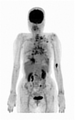
- An example of an image taken by the positron emission tomography apparatus 2 is shown.
- An example of an anatomical region specified by the region specifying unit 104 is shown.
- FIG. 1 It is a figure for demonstrating teacher data. It is a figure for demonstrating teacher data. It is a figure for demonstrating teacher data. It is a figure for demonstrating teacher data. It is a figure for demonstrating teacher data. It is a figure for demonstrating teacher data. It is a figure for demonstrating teacher data. It is a figure for demonstrating teacher data. It is a figure for demonstrating teacher data. It is a figure for demonstrating teacher data. It is a figure for demonstrating teacher data. It is a figure which showed the example of the lesion part identified by the lesion identification part 102. It is a figure which showed the example of the lesion part identified by the lesion identification part 102. It is a figure for demonstrating case 1. FIG. It is a figure for demonstrating case 1. FIG. It is a figure for demonstrating case 1. FIG. It is a figure for demonstrating case 1. FIG. It is a figure for demonstrating case 1. FIG. It is a figure for demonstrating case 1. FIG. It is a figure for demonstrating case 1.
- FIG. It is a figure for demonstrating case 1.
- FIG. It is a figure for demonstrating case 1.
- FIG. It is a figure for demonstrating case 2.
- the program for realizing the software appearing in the present embodiment may be provided as a non-transitory recording medium (Non-Transity Computer-Readable Medium) that can be read by a computer, or may be downloaded from an external server. It may be provided as possible, or it may be provided so that the program is started by an external computer and the function is realized by the client terminal (so-called cloud computing).
- Non-Transity Computer-Readable Medium Non-Transity Computer-Readable Medium
- the "part" may include, for example, a combination of hardware resources implemented by a circuit in a broad sense and information processing of software specifically realized by these hardware resources. ..
- various information is handled in this embodiment, and these information are, for example, physical values of signal values representing voltage and current, and signal values as a bit aggregate of a binary number composed of 0 or 1. It is represented by high-low or quantum superposition (so-called qubit), and communication / operation can be executed on a circuit in a broad sense.
- a circuit in a broad sense is a circuit realized by at least appropriately combining a circuit, a circuit, a processor, a memory, and the like. That is, an integrated circuit for a specific application (Application Specific Integrated Circuit: ASIC), a programmable logic device (for example, a simple programmable logic device (Simple Programmable Logic Device: SPLD), a composite programmable logic device (Complex Program)) It includes a programmable gate array (Field Programmable Gate Array: FPGA) and the like.
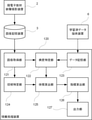
- FIG. 1 is a diagram showing an outline of the configuration of the information processing device 1 according to the embodiment of the present invention. As shown in the figure, the information processing device 1 has a processing unit 11, a storage unit 12, a temporary storage unit 13, an external device connection unit 14, and a communication unit 15, and these components are included. Is electrically connected to the inside of the information processing apparatus 1 via the communication bus 16.
- the processing unit 11 is realized by, for example, a central processing unit (CPU), operates according to a predetermined program stored in the storage unit 12, and realizes various functions.
- CPU central processing unit
- the storage unit 12 is a non-volatile storage medium that stores various information. This is realized by a storage device such as a hard disk drive (Hard Disk Drive: HDD) or a solid state drive (Solid State Drive: SSD).
- the storage unit 12 may be arranged in another device capable of communicating with the information processing device 1.
- the temporary storage unit 13 is a volatile storage medium. This is realized by, for example, a memory such as a random access memory (Random Access Memory: RAM), and temporarily stores information (arguments, arrays, etc.) required when the processing unit 11 operates.
- a memory such as a random access memory (Random Access Memory: RAM)
- RAM Random Access Memory
- the external device connection unit 14 is a connection unit conforming to a standard such as a universal serial bus (Universal Serial Bus: USB) or a high-definition multimedia interface (High-Definition Multimedia Interface: HDMI), and is an input device such as a keyboard or the like.
- a display device such as a monitor can be connected.
- the communication unit 15 is, for example, a communication means conforming to a local area network (LAN) standard, and realizes communication between the information processing device 1 and a local area network or a network such as the Internet via the information processing device 1. ..
- LAN local area network
- the information processing device 1 can be a computer for a general-purpose server, a personal computer, or the like, and the information processing device 1 can be configured by using a plurality of computers.
- the functions of the information processing device 1 will be described.
- the information processing apparatus 100 or the information processing apparatus 110 is realized by the information processing apparatus 1 operating according to the program.
- This program causes the information processing device 1 which is a computer to function as the information processing device 100 or the information processing device 110.
- Both the information processing device 100 and the information processing device 110 are information processing devices that identify the lesion portion based on the positron emission tomography examination.
- FIG. 2 is a block diagram showing a functional configuration of the information processing apparatus 100. Further, FIG. 3 is a block diagram showing a functional configuration of the information processing apparatus 110, and FIG. 4 is a block diagram showing a functional configuration of the information processing apparatus 120.
- the information processing apparatus 100 outputs an image acquisition unit 101, a lesion identification unit 102, a data storage unit 103, an area identification unit 104, an area calculation unit 105, an index calculation unit 106, and the like.
- a unit 107 is provided.
- the image acquisition unit 101 is configured to be able to acquire an image including an anatomical region photographed by the positron emission tomography apparatus 2 from the image storage apparatus 3.
- the image acquisition unit 101 can also be configured to acquire an image directly from the positron emission tomography apparatus 2 without going through the image storage apparatus 3.
- the image acquired by the image acquisition unit 101 is, for example, as shown in FIG. FIG. 5 shows an example of an image taken by the positron emission tomography apparatus 2.
- the anatomical region is a region representing a part or the whole of an anatomical structure such as an organ or tissue of the body, and here, the anatomical region is assumed to include the whole body of the subject.
- the information processing apparatus 100 can support the diagnosis by using only the chest, only the abdomen, and only the liver as the anatomical region.
- the lesion identification portion 102 is configured so that the lesion portion can be identified from the portion where the positron emitting nuclides are accumulated in the image acquired by the image acquisition unit 101 based on the learned data by machine learning.
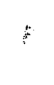
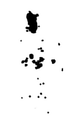
- the result of identifying the lesion portion by the lesion identification portion 102 is, for example, as shown in FIG. FIG. 6 shows an example of an image of the lesion portion identified by the lesion identification portion 102.
- the data storage unit 103 stores the learned data.
- the trained data is generated by machine learning using an image including an anatomical region taken by the positron emission tomography apparatus 2 and instruction information indicating a lesion in the image as teacher data.
- This instruction information is the one in which the lesion is instructed by a specialist.
- a deep learning algorithm called Semantic Segmentation is used. This semantic segmentation associates labels and categories with all pixels in an image, and is used to recognize a group of pixels that form a characteristic category. The details of the teacher data will be described later.
- the trained data stored in the data storage unit 103 may be periodically acquired from the trained data providing device 4 and updated.
- the region specifying unit 104 is configured to be able to identify the anatomical region in the image. If the anatomical region is whole body, the identified results will be, for example, as shown in FIG. FIG. 7 shows an example of an anatomical region specified by the region identification unit 104.
- the area calculation unit 105 is configured to be able to calculate the area of the lesion portion specified by the lesion identification unit 102 in the image acquired by the image acquisition unit 101 and the area of the anatomical region specified by the region identification unit 104.
- the area of the anatomical area is the projected area of the subject in the image acquired by the image acquisition unit 101, and preferably the area of the anatomical area is the frontal projection of the subject in the image acquired by the image acquisition unit 101.
- the area calculation unit 105 may calculate the area of the lesion based on the contour of the lesion, and may calculate the area of the anatomical region based on the contour of the anatomical region.
- the area of the lesion may be calculated based on the number of pixels, and the area of the anatomical region may be calculated based on the number of pixels of the anatomical region.
- the index calculation unit 106 is configured to be able to calculate an index from the area of the lesion portion specified by the lesion identification unit 102 in the image acquired by the image acquisition unit 101 and the area of the anatomical region specified by the region identification unit 104.
- the index is the ratio of the area of the lesion to the area of the anatomical area. Specifically, the index is the total area of the lesion divided by the area of the anatomical region, the total area of the lesion is 529.5, and the area of the whole body, which is the anatomical region, is 32729. If it is 0, the index is 0.0162.
- the output unit 107 displays the index calculated by the index calculation unit 106 on a display device (not shown), outputs data such as CSV (Comma Separated Value), or prints out on paper via a printing device (not shown). .. At this time, the output unit 107 may output the image acquired by the image acquisition unit 101 together with the index.
- CSV Common Separated Value
- the information processing apparatus 110 includes an image acquisition unit 111, a lesion identification unit 112, a data acquisition unit 113, an area identification unit 114, an area calculation unit 115, and an index calculation unit 116.
- the output unit 117 is provided.
- the image acquisition unit 111, the lesion identification unit 112, the area identification unit 114, the area calculation unit 115, the index calculation unit 116, and the output unit 117 are the image acquisition unit 101, the lesion identification unit 102, and the area of the information processing apparatus 100, respectively. Since the functions are the same as those of the specific unit 104, the area calculation unit 105, the index calculation unit 106, and the output unit 107, the description thereof is omitted here.
- the data acquisition unit 113 is configured to be able to acquire learned data from the learned data providing device 5 via a communication network.
- the trained data acquired from the trained data providing device 5 is the same type as the trained data stored in the data storage unit 103 of the information processing device 100, and is the latest trained data.
- the information processing apparatus 120 includes an image acquisition unit 121, a lesion identification unit 122, a data storage unit 123, an area identification unit 124, a volume calculation unit 125, and an index calculation unit 126. , And an output unit 127.
- the image acquisition unit 121 is configured to be able to acquire an image including an anatomical region photographed by the positron emission tomography apparatus 2 from the image storage apparatus 3.
- the image acquisition unit 121 can also be configured to acquire an image directly from the positron emission tomography apparatus 2 without going through the image storage apparatus 3.
- the lesion identification portion 122 is configured so that the lesion portion can be identified from the portion where the positron emitting nuclides are accumulated in the image acquired by the image acquisition unit 121 based on the learned data by machine learning.
- the data storage unit 123 stores the learned data.
- the trained data is generated by machine learning using an image including an anatomical region taken by the positron emission tomography apparatus 2 and instruction information indicating a lesion in the image as teacher data.
- This instruction information is the one in which the lesion is instructed by a specialist.
- the area specifying unit 124 is configured to be able to specify the anatomical region in the image acquired by the image acquisition unit 121. This image is a three-dimensional image.
- the volume calculation unit 125 is configured to be able to calculate the volume of the lesion portion specified by the lesion identification unit 122 in the image acquired by the image acquisition unit 121 and the volume of the anatomical region specified by the region identification unit 124.
- the volume of the anatomical region is the integrated volume of the tomographic image of the subject in the image acquired by the image acquisition unit 121.
- the volume calculation unit 125 may calculate the volume of the lesion based on the contour of the lesion, and may calculate the volume of the anatomical region based on the contour of the anatomical region.
- the volume of the lesion may be calculated based on the number of pixels of the tomographic image, and the volume of the anatomical region may be calculated based on the number of pixels of the anatomical region.
- the index calculation unit 126 is configured to be able to calculate an index from the volume of the lesion portion specified by the lesion identification unit 122 and the volume of the anatomical region specified by the region identification unit 124.
- the index is the ratio of the volume of the lesion to the volume of the anatomical area.
- the output unit 127 displays the index calculated by the index calculation unit 126 on a display device (not shown), outputs data such as CSV, and prints out on paper through a printing device (not shown).
- a data acquisition unit similar to the data acquisition unit 113 of the information processing apparatus 110 may be provided.
- FIG. 8 is an activity diagram showing an operation flow of the information processing apparatus 100. Since the operation of the information processing apparatus 110 can be inferred from the operation of the information processing apparatus 100, the description of the operation of the information processing apparatus 110 will be omitted.
- an input unit accepts an input of identification information (A101).
- the identification information includes information for identifying the subject (examinee, patient), a reception number for imaging by the positron emission tomography apparatus 2, and the operation differs depending on the facility, but an image taken by the positron emission tomography apparatus 2. Can be identified.
- the image acquisition unit 101 acquires an image taken by the positron emission tomography device 2 from the image storage device 3 (A102).
- the lesion identification unit 102 identifies the lesion portion from the image taken by the positron emission tomography apparatus 2 (A103), and the area calculation unit 105 calculates the area of the lesion portion (A104). ..
- the area specifying unit 104 identifies the anatomical area (A105), and the area calculation unit 105 calculates the area of the area (A106). It should be noted that these processes do not necessarily have to be performed in parallel, and the processes may be performed in the order of A103, A104, A105, A106, the order of A103, A105, A104, A106, or the like.
- the index calculation unit 106 calculates the index based on the area of the lesion and the area of the anatomical region (A107), the output unit 107 outputs the index (A108), and the information processing apparatus 100 operates. To finish.
- teacher data is an image taken by a positron emission tomography device and data that a specialist or the like points out that the lesion is a lesion among the accumulated parts of FDG contained in the image, for example, marking data that marks the lesion. It is composed of a set of.
- marking data is used as teacher data for data without lesions.
- the marking of the lesion portion corresponds to labeling (labeling whether or not the lesion is a lesion) for the accumulated portion of FDG.
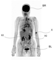
- the image taken by the positron emission tomography apparatus shown in FIG. 9 and the marking data shown in FIG. 10 form a set.
- the marking data mainly corresponds to the part where FDG is accumulated in the image taken by the positron emission tomography apparatus, excluding the brain BR, the kidney KI, and the bladder BL.
- the marking data mainly corresponds to the part where FDG is accumulated in the image taken by the positron emission tomography apparatus, excluding the brain BR, the heart HE, the kidney KI, and the bladder BL. Since the liver LI is basically a place where FDG is weakly accumulated, a strong FDG accumulation portion generated in the liver LI is marked as a lesion.
- the marking data mainly corresponds to the part where FDG is accumulated in the image taken by the positron emission tomography apparatus, excluding the brain BR, the kidney KI, and the bladder BL.
- the non-physiological accumulation part X is not a brain or kidney where FDG is generally accumulated, but a slight leak at the injection site of FDG, and a specialist or the like judges that it is not a lesion part. , Not marked.
- the marking data mainly corresponds to the part where FDG is accumulated in the image taken by the positron emission tomography apparatus, excluding the brain BR, the heart HE, the kidney KI, and the bladder BL.
- the image taken by the positron emission tomography apparatus shown in FIG. 17 and the marking data shown in FIG. 18 form a set.
- the marking data corresponds mainly to the portion where FDG is accumulated in the image taken by the positron emission tomography apparatus, excluding the brain BR, the heart HE, the kidney KI, and the bladder BL. Since it is determined that there is no lesion in the image taken by the positron emission tomography apparatus shown in 12A, the marking data is blank.
- the accumulation of FDG in areas other than the lesion does not always show the same tendency.
- the accumulation in the cardiac HE is performed. Accumulation of FDG is observed, but in the examples shown in FIGS. 13 and 14, there are cases where accumulation of FDG is not observed in the heart, so it is of great significance to use machine learning.
- an information processing device having a function of extracting an integrated portion of FDG from an image taken by a positron emission tomography apparatus and a function of specifying the contour of the extracted integrated portion is used by a specialist.
- Etc. can be made to create teacher data only by instructing the specified contour with a pointing device such as a mouse or a touch pen.
- FIGS. 19 and 20 show examples of lesions identified by the lesion identification portion 102.
- 19 and 20 are views showing an example of a lesion portion identified by the lesion identification portion 102.
- the lesion portion shown in FIG. 19 is a lesion portion identified by the lesion identification portion 102 from the image shown in FIG. 9, and the lesion portion shown in FIG. 20 is identified by the lesion identification portion 102 from the image shown in FIG. It is a lesion that has been damaged.
- FIGS. 27 to 30 are diagrams for explaining case 2
- FIGS. 31 to 34 are diagrams for explaining case 3.
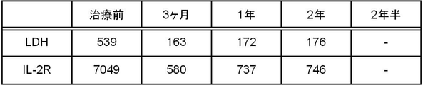
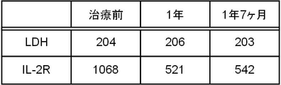
- Cases 1 to 3 are FDG-PET images taken (Interim PET) for the purpose of determining the therapeutic effect during treatment, and also LDH (serum lactate dehydrogenase) and IL-2R. (Interleukin 2 receptor) is being measured.
- FIG. 21 is an FDG-PET image taken in Case 1
- FIG. 22 shows the values of LDH and IL-2R.
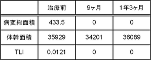
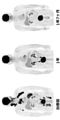
- FIG. 23 shows an image in which the lesion portion is identified by the information processing apparatus 1
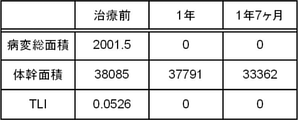
- FIG. 24 shows the result of calculating the total area of the lesion portion, the trunk area, and the TLI from the image. be.
- TLI Total Lesson Index
- FIG. 27 is an FDG-PET image taken in Case 2
- FIG. 28 shows the values of LDH and IL-2R.
- FIG. 29 shows an image in which the lesion portion is identified by the information processing apparatus 1
- FIG. 30 shows the result of calculating the total area of the lesion portion, the trunk area, and the TLI from the image. be.
- FIG. 31 is an FDG-PET image taken in Case 3
- FIG. 32 shows the values of LDH and IL-2R.
- FIG. 33 shows an image in which the lesion portion is identified by the information processing apparatus 1, and
- FIG. 34 shows the result of calculating the total area of the lesion portion, the trunk area, and the TLI from the image. be.
- the information processing apparatus includes a region specifying unit, a volume calculation unit, and an index calculation unit.
- the region specifying unit is configured to be able to specify an anatomical region in the image, and the image is three-dimensional. It is an image, the volume calculation unit is configured to be able to calculate the volume of the lesion and the volume of the anatomical region, the index calculation unit is configured to be able to calculate the index, and the index is the index.
- An information processing device that is the ratio of the volume of the lesion to the volume of the anatomical region. In the information processing device, the volume of the anatomical region is the integrated volume of the tomographic image of the subject in the image.
- the volume calculation unit calculates the volume of the lesion portion based on the contour of the lesion portion, and calculates the volume of the anatomical region based on the contour of the anatomical region.
- Processing equipment In the information processing apparatus, the volume calculation unit calculates the volume of the lesion based on the number of pixels of the tomographic image of the lesion, and the volume calculation unit calculates the volume of the lesion based on the number of pixels of the anatomical region.
- An information processing device that calculates the volume.
- the information processing apparatus includes an area specifying unit, an area calculation unit, and an index calculation unit.
- the area specifying unit is configured to be able to specify an anatomical region in the image, and the area calculation unit is configured.
- the area of the lesion and the area of the anatomical region can be calculated.
- the area of the anatomical region is the projected area of the subject in the image, and the index calculation unit calculates the index.
- An information processing device that is configured to be possible and the index is the ratio of the area of the lesion to the area of the anatomical region.
- the area of the anatomical region is the front projection area of the subject in the image.
- the area calculation unit calculates the area of the lesion based on the contour of the lesion, and calculates the area of the anatomical region based on the contour of the anatomical region. Processing equipment.
- the area calculation unit calculates the area of the lesion based on the number of pixels of the lesion, and calculates the area of the anatomical region based on the number of pixels of the anatomical region.
- Information processing equipment In the information processing device, the anatomical region is an information processing device including the whole body of the subject.
- the information processing device includes a data storage unit, and the data storage unit is an information processing device that stores the learned data.
- the information processing device includes a data acquisition unit, and the data acquisition unit is an information processing device configured to be able to acquire the trained data from the trained data providing device via a communication network.
- the learned data is generated by machine learning using an image including an anatomical region taken by the positron radiation tomography apparatus and instruction information indicating a lesion in the image as teacher data.
- the instruction information is an information processing device in which a lesion portion is instructed by a specialist.
- the lesion can be automatically identified from the test result of the positron emission tomography apparatus, the test result can be easily grasped even by a specialist, even if the specialist is not a specialist. , The labor required to grasp the inspection result can be reduced.
- the lesion can be quantitatively evaluated, so that it is possible to grasp the state transition of cancer or inflammation in the same manner as grasping the result of the blood test, for example.
- Information processing device 2 Positive electron radiation tomography device 3: Image storage device 4: Learned data providing device 5: Learned data providing device 6: Learned data providing device 11: Processing unit 12: Storage unit 13: Temporary storage Unit 14: External device connection unit 15: Communication unit 16: Communication bus 100: Information processing device 101: Image acquisition unit 102: Disease identification unit 103: Data storage unit 104: Area identification unit 105: Area calculation unit 106: Index calculation unit 107: Output unit 110: Information processing device 111: Image acquisition unit 112: Disease identification unit 113: Data acquisition unit 114: Area identification unit 115: Area calculation unit 116: Index calculation unit 117: Output unit 120: Information processing device 121: Image acquisition unit 122: Disease identification unit 123: Data acquisition unit 124: Area identification unit 125: Volume calculation unit 126: Index calculation unit 127: Output unit BL: Bladder BR: Brain HE: Heart KI: Kidney LI: Liver X: Non Physiological accumulation part
Abstract
[Problem] To provide an information processing device and program capable of supporting a diagnosis performed by a doctor, by automatically identifying a lesioned portion from the result of a positron emission tomography (PET) examination. [Solution] One aspect of the present invention provides an information processing device for identifying a lesioned portion on the basis of a positron emission tomography examination. The information processing device is provided with an image acquiring unit, and a lesion identifying unit. The image acquiring unit is configured to be capable of acquiring an image including an anatomical region imaged by a positron emission tomography device. The lesion identifying unit is configured to be capable of identifying a lesioned portion from a part of the image in which positron-emitting radionuclides are accumulated, on the basis of trained data obtained by machine learning.
Description
本発明は、情報処理装置及びプログラムに関する。
The present invention relates to an information processing device and a program.
近年、検査結果の画像に基づく診断をコンピュータにより支援する技術が提案されている(例えば、特許文献1を参照)。
In recent years, a technique for supporting a diagnosis based on an image of a test result by a computer has been proposed (see, for example, Patent Document 1).
また、最近では、医療分野においても、ディープラーニング等を利用して画像の特徴を認識することが望まれており、これを支援するための技術も提案されている(例えば、特許文献2を参照)。
Recently, in the medical field as well, it is desired to recognize the features of an image by using deep learning or the like, and a technique for supporting this has been proposed (see, for example, Patent Document 2). ).
ところで、画像を利用する検査には、ブドウ糖のアナログ分子に陽電子放出核種F-18を標識したFDG(fluorodeoxyglucose:フルオロデオキシグルコース)という薬剤を用いたPET(positron emission tomography:陽電子放射断層撮影)検査がある。このPET検査は、癌や炎症といった病変部に集積し、画像から病変を見付けるのを容易にしている。
By the way, PET (positron emission tomography) inspection using a drug called FDG (fluorodeoxyglucose: fluorodeoxyglucose) in which an analog molecule of glucose is labeled with positron emitting nuclei F-18 is one of the inspections using images. be. This PET examination accumulates in lesions such as cancer and inflammation, making it easier to find lesions from images.
しかしながら、脳や心臓などの臓器は元々ブドウ糖代謝が盛んであるため、FDGの生理的な集積が認められる。また、FDGは尿に排泄されるため、腎臓や尿管、膀胱にもFDGが集積している。そのため、PET検査では、病変部を自動的に抽出する事が難しい。このことから、全身の病変の広がりを定量化することが出来ない。
However, since glucose metabolism is originally active in organs such as the brain and heart, physiological accumulation of FDG is observed. In addition, since FDG is excreted in urine, FDG is also accumulated in the kidney, ureter, and bladder. Therefore, it is difficult to automatically extract the lesion in the PET examination. Therefore, it is not possible to quantify the spread of lesions throughout the body.
本発明では上記事情を鑑み、PET検査の結果から病変部を自動的に特定し、医師による診断を支援することのできる情報処理装置及びプログラムを提供することとした。
In view of the above circumstances, the present invention has decided to provide an information processing device and a program capable of automatically identifying a lesion from the result of a PET examination and supporting a diagnosis by a doctor.
本発明の一態様によれば、陽電子放射断層撮影検査に基づいて病変部の特定を行う情報処理装置が提供される。この情報処理装置は、画像取得部と、病変特定部とを備える。画像取得部は、陽電子放射断層撮影装置が撮影した解剖学的領域を含む画像を取得可能に構成される。病変特定部は、機械学習による学習済データに基づいて、画像中の陽電子放出核種が集積された部分から病変部を特定可能に構成される。
According to one aspect of the present invention, there is provided an information processing apparatus that identifies a lesion based on a positron emission tomography examination. This information processing device includes an image acquisition unit and a lesion identification unit. The image acquisition unit is configured to be able to acquire an image including an anatomical region taken by a positron emission tomography apparatus. The lesion identification part is configured so that the lesion part can be identified from the part where the positron emitting nuclides are accumulated in the image based on the learned data by machine learning.
本発明の一態様によれば、PET検査の結果に基づく診断を支援し、医師の負荷を低減することが可能となる。
According to one aspect of the present invention, it is possible to support the diagnosis based on the result of the PET examination and reduce the burden on the doctor.
以下、図面を用いて本発明の実施形態について説明する。以下に示す実施形態中で示した各種特徴事項は、互いに組み合わせ可能である。
Hereinafter, embodiments of the present invention will be described with reference to the drawings. The various features shown in the embodiments shown below can be combined with each other.
ところで、本実施形態に登場するソフトウェアを実現するためのプログラムは、コンピュータが読み取り可能な非一時的な記録媒体(Non-Transitory Computer-Readable Medium)として提供されてもよいし、外部のサーバからダウンロード可能に提供されてもよいし、外部のコンピュータで当該プログラムを起動させてクライアント端末でその機能を実現(いわゆるクラウドコンピューティング)するように提供されてもよい。
By the way, the program for realizing the software appearing in the present embodiment may be provided as a non-transitory recording medium (Non-Transity Computer-Readable Medium) that can be read by a computer, or may be downloaded from an external server. It may be provided as possible, or it may be provided so that the program is started by an external computer and the function is realized by the client terminal (so-called cloud computing).
また、本実施形態において「部」とは、例えば、広義の回路によって実施されるハードウェア資源と、これらのハードウェア資源によって具体的に実現されうるソフトウェアの情報処理とを合わせたものも含みうる。また、本実施形態においては様々な情報を取り扱うが、これら情報は、例えば電圧・電流を表す信号値の物理的な値、0又は1で構成される2進数のビット集合体としての信号値の高低、又は量子的な重ね合わせ(いわゆる量子ビット)によって表され、広義の回路上で通信・演算が実行されうる。
Further, in the present embodiment, the "part" may include, for example, a combination of hardware resources implemented by a circuit in a broad sense and information processing of software specifically realized by these hardware resources. .. In addition, various information is handled in this embodiment, and these information are, for example, physical values of signal values representing voltage and current, and signal values as a bit aggregate of a binary number composed of 0 or 1. It is represented by high-low or quantum superposition (so-called qubit), and communication / operation can be executed on a circuit in a broad sense.
また、広義の回路とは、回路(Circuit)、回路類(Circuitry)、プロセッサ(Processor)、及びメモリ(Memory)等を少なくとも適当に組み合わせることによって実現される回路である。すなわち、特定用途向け集積回路(Application Specific Integrated Circuit:ASIC)、プログラマブル論理デバイス(例えば、単純プログラマブル論理デバイス(Simple Programmable Logic Device:SPLD)、複合プログラマブル論理デバイス(Complex Programmable Logic Device:CPLD)、及びフィールドプログラマブルゲートアレイ(Field Programmable Gate Array:FPGA))等を含むものである。
Further, a circuit in a broad sense is a circuit realized by at least appropriately combining a circuit, a circuit, a processor, a memory, and the like. That is, an integrated circuit for a specific application (Application Specific Integrated Circuit: ASIC), a programmable logic device (for example, a simple programmable logic device (Simple Programmable Logic Device: SPLD), a composite programmable logic device (Complex Program)) It includes a programmable gate array (Field Programmable Gate Array: FPGA) and the like.
1.情報処理装置の構成
図1は、本発明の実施形態に係る情報処理装置1の構成の概略を示した図である。同図に示すように、情報処理装置1は、処理部11と、記憶部12と、一時記憶部13と、外部装置接続部14と、通信部15とを有しており、これらの構成要素が情報処理装置1の内部において通信バス16を介して電気的に接続されている。 1. 1. Configuration of Information Processing Device FIG. 1 is a diagram showing an outline of the configuration of the information processing device 1 according to the embodiment of the present invention. As shown in the figure, the information processing device 1 has aprocessing unit 11, a storage unit 12, a temporary storage unit 13, an external device connection unit 14, and a communication unit 15, and these components are included. Is electrically connected to the inside of the information processing apparatus 1 via the communication bus 16.
図1は、本発明の実施形態に係る情報処理装置1の構成の概略を示した図である。同図に示すように、情報処理装置1は、処理部11と、記憶部12と、一時記憶部13と、外部装置接続部14と、通信部15とを有しており、これらの構成要素が情報処理装置1の内部において通信バス16を介して電気的に接続されている。 1. 1. Configuration of Information Processing Device FIG. 1 is a diagram showing an outline of the configuration of the information processing device 1 according to the embodiment of the present invention. As shown in the figure, the information processing device 1 has a
処理部11は、例えば、中央処理装置(Central Processing Unit:CPU)により実現されるもので、記憶部12に記憶された所定のプログラムに従って動作し、種々の機能を実現する。
The processing unit 11 is realized by, for example, a central processing unit (CPU), operates according to a predetermined program stored in the storage unit 12, and realizes various functions.
記憶部12は、様々な情報を記憶する不揮発性の記憶媒体である。これは、例えばハードディスクドライブ(Hard Disk Drive:HDD)やソリッドステートドライブ(Solid State Drive:SSD)等のストレージデバイスにより実現される。なお、記憶部12は、情報処理装置1と通信可能な別の装置に配するようにすることも可能である。
The storage unit 12 is a non-volatile storage medium that stores various information. This is realized by a storage device such as a hard disk drive (Hard Disk Drive: HDD) or a solid state drive (Solid State Drive: SSD). The storage unit 12 may be arranged in another device capable of communicating with the information processing device 1.
一時記憶部13は、揮発性の記憶媒体である。これは、例えばランダムアクセスメモリ(Random Access Memory:RAM)等のメモリにより実現され、処理部11が動作する際に一時的に必要な情報(引数、配列等)を記憶する。
The temporary storage unit 13 is a volatile storage medium. This is realized by, for example, a memory such as a random access memory (Random Access Memory: RAM), and temporarily stores information (arguments, arrays, etc.) required when the processing unit 11 operates.
外部装置接続部14は、例えばユニバーサルシリアルバス(Universal Serial Bus:USB)や高精細度マルチメディアインターフェース(High-Definition Multimedia Interface:HDMI)といった規格に準じた接続部であり、キーボード等の入力装置やモニタ等の表示装置を接続可能としている。
The external device connection unit 14 is a connection unit conforming to a standard such as a universal serial bus (Universal Serial Bus: USB) or a high-definition multimedia interface (High-Definition Multimedia Interface: HDMI), and is an input device such as a keyboard or the like. A display device such as a monitor can be connected.
通信部15は、例えばローカルエリアネットワーク(Local Area Network:LAN)規格に準じた通信手段であり、情報処理装置1とローカルエリアネットワークやこれを介したインターネット等のネットワークとの間の通信を実現する。
The communication unit 15 is, for example, a communication means conforming to a local area network (LAN) standard, and realizes communication between the information processing device 1 and a local area network or a network such as the Internet via the information processing device 1. ..
なお、情報処理装置1には、汎用のサーバ向けのコンピュータやパーソナルコンピュータ等を利用することが可能であり、複数のコンピュータを用いて情報処理装置1を構成することも可能である。
The information processing device 1 can be a computer for a general-purpose server, a personal computer, or the like, and the information processing device 1 can be configured by using a plurality of computers.
2.情報処理装置の機能
次に、情報処理装置1の機能について説明する。なお、ここでは、情報処理装置1がプログラムにしたがって動作することで、情報処理装置100又は情報処理装置110を実現させるものとする。このプログラムは、コンピュータである情報処理装置1を情報処理装置100又は情報処理装置110として機能させるものである。情報処理装置100と情報処理装置110は、いずれも、陽電子放射断層撮影検査に基づいて病変部の特定を行う情報処理装置である。 2. 2. Functions of Information Processing Device Next, the functions of the information processing device 1 will be described. Here, it is assumed that theinformation processing apparatus 100 or the information processing apparatus 110 is realized by the information processing apparatus 1 operating according to the program. This program causes the information processing device 1 which is a computer to function as the information processing device 100 or the information processing device 110. Both the information processing device 100 and the information processing device 110 are information processing devices that identify the lesion portion based on the positron emission tomography examination.
次に、情報処理装置1の機能について説明する。なお、ここでは、情報処理装置1がプログラムにしたがって動作することで、情報処理装置100又は情報処理装置110を実現させるものとする。このプログラムは、コンピュータである情報処理装置1を情報処理装置100又は情報処理装置110として機能させるものである。情報処理装置100と情報処理装置110は、いずれも、陽電子放射断層撮影検査に基づいて病変部の特定を行う情報処理装置である。 2. 2. Functions of Information Processing Device Next, the functions of the information processing device 1 will be described. Here, it is assumed that the
図2は、情報処理装置100の機能的な構成を示すブロック図である。また、図3は、情報処理装置110の機能的な構成を示すブロック図であり、図4は、情報処理装置120の機能的な構成を示すブロック図である。
FIG. 2 is a block diagram showing a functional configuration of the information processing apparatus 100. Further, FIG. 3 is a block diagram showing a functional configuration of the information processing apparatus 110, and FIG. 4 is a block diagram showing a functional configuration of the information processing apparatus 120.
図2に示すように、情報処理装置100は、画像取得部101と、病変特定部102と、データ記憶部103と、領域特定部104と、面積算出部105と、指標算出部106と、出力部107とを備える。
As shown in FIG. 2, the information processing apparatus 100 outputs an image acquisition unit 101, a lesion identification unit 102, a data storage unit 103, an area identification unit 104, an area calculation unit 105, an index calculation unit 106, and the like. A unit 107 is provided.
画像取得部101は、画像記憶装置3から陽電子放射断層撮影装置2が撮影した解剖学的領域を含む画像を取得可能に構成される。なお、画像取得部101は、画像記憶装置3を介さずに陽電子放射断層撮影装置2から直接画像を取得するように構成することもできる。画像取得部101が取得する画像は、例えば、図5に示すようなものである。図5は、陽電子放射断層撮影装置2が撮影した画像の例を示したものである。
The image acquisition unit 101 is configured to be able to acquire an image including an anatomical region photographed by the positron emission tomography apparatus 2 from the image storage apparatus 3. The image acquisition unit 101 can also be configured to acquire an image directly from the positron emission tomography apparatus 2 without going through the image storage apparatus 3. The image acquired by the image acquisition unit 101 is, for example, as shown in FIG. FIG. 5 shows an example of an image taken by the positron emission tomography apparatus 2.
解剖学的領域は、体の臓器または組織などの解剖学的な構造物の一部または全体を表す領域であり、ここでは、解剖学的領域は、被験者の全身を含むものとする。もちろん、情報処理装置100は、胸部のみ、腹部のみ、肝臓のみを解剖学的領域として、診断の支援をすることが可能である。
The anatomical region is a region representing a part or the whole of an anatomical structure such as an organ or tissue of the body, and here, the anatomical region is assumed to include the whole body of the subject. Of course, the information processing apparatus 100 can support the diagnosis by using only the chest, only the abdomen, and only the liver as the anatomical region.
病変特定部102は、機械学習による学習済データに基づいて、画像取得部101が取得した画像中の陽電子放出核種が集積された部分から病変部を特定可能に構成される。病変特定部102による病変部の特定結果は、例えば、図6に示すようなものとなる。図6は、病変特定部102が特定した病変部の画像の例を示したものである。
The lesion identification portion 102 is configured so that the lesion portion can be identified from the portion where the positron emitting nuclides are accumulated in the image acquired by the image acquisition unit 101 based on the learned data by machine learning. The result of identifying the lesion portion by the lesion identification portion 102 is, for example, as shown in FIG. FIG. 6 shows an example of an image of the lesion portion identified by the lesion identification portion 102.
データ記憶部103は、学習済データを記憶する。学習済データは、陽電子放射断層撮影装置2が撮影した解剖学的領域を含む画像と、該画像中の病変部を指示する指示情報とを教師データとした機械学習により生成される。この指示情報は、専門医により病変部が指示されたものである。機械学習には、例えば、セマンティック セグメンテーション(Semantic Segmentation)と称されるディープラーニング (Deep Learning) のアルゴリズムを用いる。このセマンティック セグメンテーションは、画像内の全画素にラベルやカテゴリを関連付けるもので、特徴的なカテゴリを形成する画素の集まりを認識するために使用されるものである。なお、教師データの詳細についは、後述する。また、データ記憶部103に記憶される学習済データは、定期的に学習済データ提供装置4から最新のものを取得して更新するようにしてもよい。
The data storage unit 103 stores the learned data. The trained data is generated by machine learning using an image including an anatomical region taken by the positron emission tomography apparatus 2 and instruction information indicating a lesion in the image as teacher data. This instruction information is the one in which the lesion is instructed by a specialist. For machine learning, for example, a deep learning algorithm called Semantic Segmentation is used. This semantic segmentation associates labels and categories with all pixels in an image, and is used to recognize a group of pixels that form a characteristic category. The details of the teacher data will be described later. Further, the trained data stored in the data storage unit 103 may be periodically acquired from the trained data providing device 4 and updated.
領域特定部104は、画像中の解剖学的領域を特定可能に構成される。解剖学的領域が全身である場合、特定された結果は、例えば、図7に示すようなものとなる。図7は、領域特定部104が特定した解剖学的領域の例を示したものである。
The region specifying unit 104 is configured to be able to identify the anatomical region in the image. If the anatomical region is whole body, the identified results will be, for example, as shown in FIG. FIG. 7 shows an example of an anatomical region specified by the region identification unit 104.
面積算出部105は、画像取得部101が取得した画像中の病変特定部102が特定した病変部の面積と領域特定部104が特定した解剖学的領域の面積とを算出可能に構成される。解剖学的領域の面積は、画像取得部101が取得した画像中の被験者の投影面積であり、好ましくは、解剖学的領域の面積は、画像取得部101が取得した画像中の被験者の正面投影面積である。面積算出部105は、病変部の輪郭に基づいて該病変部の面積を算出し、解剖学的領域の輪郭に基づいて該解剖学的領域の面積を算出するようにしてもよく、病変部の画素数に基づいて該病変部の面積を算出し、解剖学的領域の画素数に基づいて該解剖学的領域の面積を算出するようにしてもよい。
The area calculation unit 105 is configured to be able to calculate the area of the lesion portion specified by the lesion identification unit 102 in the image acquired by the image acquisition unit 101 and the area of the anatomical region specified by the region identification unit 104. The area of the anatomical area is the projected area of the subject in the image acquired by the image acquisition unit 101, and preferably the area of the anatomical area is the frontal projection of the subject in the image acquired by the image acquisition unit 101. The area. The area calculation unit 105 may calculate the area of the lesion based on the contour of the lesion, and may calculate the area of the anatomical region based on the contour of the anatomical region. The area of the lesion may be calculated based on the number of pixels, and the area of the anatomical region may be calculated based on the number of pixels of the anatomical region.
指標算出部106は、画像取得部101が取得した画像中の病変特定部102が特定した病変部の面積と領域特定部104が特定した解剖学的領域の面積とから指標を算出可能に構成される。指標は、病変部の面積と解剖学的領域の面積との比である。具体的には、指標は、病変部の総面積を解剖学的領域の面積で除したものであり、病変部の総面積が529.5で、解剖学的領域である全身の面積が32729.0であれば、指標は、0.0162となる。
The index calculation unit 106 is configured to be able to calculate an index from the area of the lesion portion specified by the lesion identification unit 102 in the image acquired by the image acquisition unit 101 and the area of the anatomical region specified by the region identification unit 104. To. The index is the ratio of the area of the lesion to the area of the anatomical area. Specifically, the index is the total area of the lesion divided by the area of the anatomical region, the total area of the lesion is 529.5, and the area of the whole body, which is the anatomical region, is 32729. If it is 0, the index is 0.0162.
出力部107は、指標算出部106が算出した指標を、図示しない表示装置に表示したり、CSV(Comma Separated Value)などのデータ出力をしたり、図示しない印刷装置を介して紙面に印刷出力する。このとき、出力部107は、画像取得部101が取得した画像を指標と併せて出力するようにしてもよい。
The output unit 107 displays the index calculated by the index calculation unit 106 on a display device (not shown), outputs data such as CSV (Comma Separated Value), or prints out on paper via a printing device (not shown). .. At this time, the output unit 107 may output the image acquired by the image acquisition unit 101 together with the index.
また、図3に示すように、情報処理装置110は、画像取得部111と、病変特定部112と、データ取得部113と、領域特定部114と、面積算出部115と、指標算出部116と、出力部117とを備える。なお、画像取得部111、病変特定部112、領域特定部114、面積算出部115、指標算出部116、出力部117は、それぞれ、情報処理装置100の画像取得部101、病変特定部102、領域特定部104、面積算出部105、指標算出部106、出力部107と同様の機能部であるため、ここでの説明は省略する。
Further, as shown in FIG. 3, the information processing apparatus 110 includes an image acquisition unit 111, a lesion identification unit 112, a data acquisition unit 113, an area identification unit 114, an area calculation unit 115, and an index calculation unit 116. , The output unit 117 is provided. The image acquisition unit 111, the lesion identification unit 112, the area identification unit 114, the area calculation unit 115, the index calculation unit 116, and the output unit 117 are the image acquisition unit 101, the lesion identification unit 102, and the area of the information processing apparatus 100, respectively. Since the functions are the same as those of the specific unit 104, the area calculation unit 105, the index calculation unit 106, and the output unit 107, the description thereof is omitted here.
データ取得部113は、通信ネットワークを介して学習済データ提供装置5から学習済データを取得可能に構成される。学習済データ提供装置5から取得する学習済データは、情報処理装置100のデータ記憶部103が記憶している学習済データと同種のもので、最新の学習済データである。
The data acquisition unit 113 is configured to be able to acquire learned data from the learned data providing device 5 via a communication network. The trained data acquired from the trained data providing device 5 is the same type as the trained data stored in the data storage unit 103 of the information processing device 100, and is the latest trained data.
また、図4に示すように、情報処理装置120は、画像取得部121と、病変特定部122と、データ記憶部123と、領域特定部124と、体積算出部125と、指標算出部126と、出力部127とを備える。
Further, as shown in FIG. 4, the information processing apparatus 120 includes an image acquisition unit 121, a lesion identification unit 122, a data storage unit 123, an area identification unit 124, a volume calculation unit 125, and an index calculation unit 126. , And an output unit 127.
画像取得部121は、画像記憶装置3から陽電子放射断層撮影装置2が撮影した解剖学的領域を含む画像を取得可能に構成される。なお、画像取得部121は、画像記憶装置3を介さずに陽電子放射断層撮影装置2から直接画像を取得するように構成することもできる。
The image acquisition unit 121 is configured to be able to acquire an image including an anatomical region photographed by the positron emission tomography apparatus 2 from the image storage apparatus 3. The image acquisition unit 121 can also be configured to acquire an image directly from the positron emission tomography apparatus 2 without going through the image storage apparatus 3.
病変特定部122は、機械学習による学習済データに基づいて、画像取得部121が取得した画像中の陽電子放出核種が集積された部分から病変部を特定可能に構成される。
The lesion identification portion 122 is configured so that the lesion portion can be identified from the portion where the positron emitting nuclides are accumulated in the image acquired by the image acquisition unit 121 based on the learned data by machine learning.
データ記憶部123は、学習済データを記憶する。学習済データは、陽電子放射断層撮影装置2が撮影した解剖学的領域を含む画像と、該画像中の病変部を指示する指示情報とを教師データとした機械学習により生成される。この指示情報は、専門医により病変部が指示されたものである。
The data storage unit 123 stores the learned data. The trained data is generated by machine learning using an image including an anatomical region taken by the positron emission tomography apparatus 2 and instruction information indicating a lesion in the image as teacher data. This instruction information is the one in which the lesion is instructed by a specialist.
領域特定部124は、画像取得部121が取得した画像中の解剖学的領域を特定可能に構成される。この画像は、3次元画像である。
The area specifying unit 124 is configured to be able to specify the anatomical region in the image acquired by the image acquisition unit 121. This image is a three-dimensional image.
また、体積算出部125は、画像取得部121が取得した画像中の病変特定部122が特定した病変部の体積と領域特定部124が特定した解剖学的領域の体積とを算出可能に構成される。解剖学的領域の体積は、画像取得部121が取得した画像中の被験者の断層画像の積算体積である。
体積算出部125は、病変部の輪郭に基づいて該病変部の体積を算出し、解剖学的領域の輪郭に基づいて該解剖学的領域の体積を算出するようにしてもよく、病変部の断層画像の画素数に基づいて該病変部の体積を算出し、解剖学的領域の画素数に基づいて該解剖学的領域の体積を算出するようにしてもよい。 Further, thevolume calculation unit 125 is configured to be able to calculate the volume of the lesion portion specified by the lesion identification unit 122 in the image acquired by the image acquisition unit 121 and the volume of the anatomical region specified by the region identification unit 124. To. The volume of the anatomical region is the integrated volume of the tomographic image of the subject in the image acquired by the image acquisition unit 121.
Thevolume calculation unit 125 may calculate the volume of the lesion based on the contour of the lesion, and may calculate the volume of the anatomical region based on the contour of the anatomical region. The volume of the lesion may be calculated based on the number of pixels of the tomographic image, and the volume of the anatomical region may be calculated based on the number of pixels of the anatomical region.
体積算出部125は、病変部の輪郭に基づいて該病変部の体積を算出し、解剖学的領域の輪郭に基づいて該解剖学的領域の体積を算出するようにしてもよく、病変部の断層画像の画素数に基づいて該病変部の体積を算出し、解剖学的領域の画素数に基づいて該解剖学的領域の体積を算出するようにしてもよい。 Further, the
The
指標算出部126は、病変特定部122が特定した病変部の体積と領域特定部124が特定した解剖学的領域の体積とから指標を算出可能に構成される。指標は、病変部の体積と解剖学的領域の体積との比である。
The index calculation unit 126 is configured to be able to calculate an index from the volume of the lesion portion specified by the lesion identification unit 122 and the volume of the anatomical region specified by the region identification unit 124. The index is the ratio of the volume of the lesion to the volume of the anatomical area.
出力部127は、指標算出部126が算出した指標を、図示しない表示装置に表示したり、CSVなどのデータ出力をしたり、図示しない印刷装置を介して紙面に印刷出力する。なお、データ記憶部123に代えて、情報処理装置110のデータ取得部113と同様のデータ取得部を備えるようにしてもよい。
The output unit 127 displays the index calculated by the index calculation unit 126 on a display device (not shown), outputs data such as CSV, and prints out on paper through a printing device (not shown). Instead of the data storage unit 123, a data acquisition unit similar to the data acquisition unit 113 of the information processing apparatus 110 may be provided.
3.情報処理装置の動作
次に、情報処理装置100の動作について説明する。図8は、情報処理装置100の動作の流れを示すアクティビティ図である。なお、情報処理装置110の動作については、情報処理装置100の動作から類推可能であるため、情報処理装置110の動作の説明については省略する。 3. 3. Operation of Information Processing Device Next, the operation of theinformation processing device 100 will be described. FIG. 8 is an activity diagram showing an operation flow of the information processing apparatus 100. Since the operation of the information processing apparatus 110 can be inferred from the operation of the information processing apparatus 100, the description of the operation of the information processing apparatus 110 will be omitted.
次に、情報処理装置100の動作について説明する。図8は、情報処理装置100の動作の流れを示すアクティビティ図である。なお、情報処理装置110の動作については、情報処理装置100の動作から類推可能であるため、情報処理装置110の動作の説明については省略する。 3. 3. Operation of Information Processing Device Next, the operation of the
情報処理装置100は、動作を開始すると、まず、図示しない入力部が、識別情報の入力を受け付ける(A101)。識別情報は、被験者(受診者、患者)を識別する情報や、陽電子放射断層撮影装置2による撮影の受付番号等であり、施設によりその運用は異なるが、陽電子放射断層撮影装置2が撮影した画像を識別できるものである。
When the information processing apparatus 100 starts operation, first, an input unit (not shown) accepts an input of identification information (A101). The identification information includes information for identifying the subject (examinee, patient), a reception number for imaging by the positron emission tomography apparatus 2, and the operation differs depending on the facility, but an image taken by the positron emission tomography apparatus 2. Can be identified.
情報処理装置100は、識別情報を受け付けると、画像取得部101が画像記憶装置3から陽電子放射断層撮影装置2が撮影した画像を取得する(A102)。
When the information processing device 100 receives the identification information, the image acquisition unit 101 acquires an image taken by the positron emission tomography device 2 from the image storage device 3 (A102).
続いて、情報処理装置100は、病変特定部102が、陽電子放射断層撮影装置2が撮影した画像から病変部を特定し(A103)、面積算出部105が病変部の面積を算出する(A104)。このとき、領域特定部104が解剖学的領域を特定し(A105)、面積算出部105が当該領域の面積を算出する(A106)。なお、これらの処理は、必ずしも並列で行う必要はなく、A103、A104、A105、A106の順や、A103、A105、A104、A106の順等で処理を行うようにすることもできる。
Subsequently, in the information processing apparatus 100, the lesion identification unit 102 identifies the lesion portion from the image taken by the positron emission tomography apparatus 2 (A103), and the area calculation unit 105 calculates the area of the lesion portion (A104). .. At this time, the area specifying unit 104 identifies the anatomical area (A105), and the area calculation unit 105 calculates the area of the area (A106). It should be noted that these processes do not necessarily have to be performed in parallel, and the processes may be performed in the order of A103, A104, A105, A106, the order of A103, A105, A104, A106, or the like.
そして、指標算出部106が、病変部の面積と解剖学的領域の面積に基づいて指標を算出し(A107)、出力部107が指標を出力して(A108)、情報処理装置100は、動作を終了する。
Then, the index calculation unit 106 calculates the index based on the area of the lesion and the area of the anatomical region (A107), the output unit 107 outputs the index (A108), and the information processing apparatus 100 operates. To finish.
4.教師データ
次に、教師データについて説明する。図9乃至図18は、教師データを説明するための図である。教師データは、陽電子放射断層撮影装置により撮影された画像と、当該画像に含まれるFDGの集積部分のうち、専門医等が病変部である旨を指摘したデータ、例えば、病変部をマーキングしたマーキングデータの組により構成される。また、脳や心臓、腎臓や尿管や膀胱などの正常部位へのFDGの集積を病変でないと認識させる精度を上げるために、病変部のないデータに対して、マーキングのない白紙データを教師データとして利用する。なお、病変部のマーキングは、FDGの集積部分に対するラベリング(病変部であるか否かのラベル設定)に相当する。 4. Teacher data Next, teacher data will be described. 9 to 18 are diagrams for explaining teacher data. The teacher data is an image taken by a positron emission tomography device and data that a specialist or the like points out that the lesion is a lesion among the accumulated parts of FDG contained in the image, for example, marking data that marks the lesion. It is composed of a set of. In addition, in order to improve the accuracy of recognizing the accumulation of FDG in normal parts such as the brain, heart, kidneys, ureters, and bladder as non-lesions, blank data without markings is used as teacher data for data without lesions. Use as. The marking of the lesion portion corresponds to labeling (labeling whether or not the lesion is a lesion) for the accumulated portion of FDG.
次に、教師データについて説明する。図9乃至図18は、教師データを説明するための図である。教師データは、陽電子放射断層撮影装置により撮影された画像と、当該画像に含まれるFDGの集積部分のうち、専門医等が病変部である旨を指摘したデータ、例えば、病変部をマーキングしたマーキングデータの組により構成される。また、脳や心臓、腎臓や尿管や膀胱などの正常部位へのFDGの集積を病変でないと認識させる精度を上げるために、病変部のないデータに対して、マーキングのない白紙データを教師データとして利用する。なお、病変部のマーキングは、FDGの集積部分に対するラベリング(病変部であるか否かのラベル設定)に相当する。 4. Teacher data Next, teacher data will be described. 9 to 18 are diagrams for explaining teacher data. The teacher data is an image taken by a positron emission tomography device and data that a specialist or the like points out that the lesion is a lesion among the accumulated parts of FDG contained in the image, for example, marking data that marks the lesion. It is composed of a set of. In addition, in order to improve the accuracy of recognizing the accumulation of FDG in normal parts such as the brain, heart, kidneys, ureters, and bladder as non-lesions, blank data without markings is used as teacher data for data without lesions. Use as. The marking of the lesion portion corresponds to labeling (labeling whether or not the lesion is a lesion) for the accumulated portion of FDG.
例えば、図9に示す陽電子放射断層撮影装置により撮影された画像と、図10に示すマーキングデータが組となる。マーキングデータは、陽電子放射断層撮影装置により撮影された画像中のFDGが集積された部分のうち、主として、脳BR、腎臓KI、膀胱BLを除いた部分に相当する。
For example, the image taken by the positron emission tomography apparatus shown in FIG. 9 and the marking data shown in FIG. 10 form a set. The marking data mainly corresponds to the part where FDG is accumulated in the image taken by the positron emission tomography apparatus, excluding the brain BR, the kidney KI, and the bladder BL.
また、図11に示す陽電子放射断層撮影装置により撮影された画像と、図12に示すマーキングデータが組となる。マーキングデータは、陽電子放射断層撮影装置により撮影された画像中のFDGが集積された部分のうち、主として、脳BR、心臓HE、腎臓KI、膀胱BLを除いた部分に相当する。肝臓LIは、基本的にFDGが弱く集積する場所であるため、肝臓LIに生じている強いFDGの集積部分が、病変部としてマーキングされる。
Further, the image taken by the positron emission tomography apparatus shown in FIG. 11 and the marking data shown in FIG. 12 form a set. The marking data mainly corresponds to the part where FDG is accumulated in the image taken by the positron emission tomography apparatus, excluding the brain BR, the heart HE, the kidney KI, and the bladder BL. Since the liver LI is basically a place where FDG is weakly accumulated, a strong FDG accumulation portion generated in the liver LI is marked as a lesion.
また、図13に示す陽電子放射断層撮影装置により撮影された画像と、図14に示すマーキングデータが組となる。マーキングデータは、陽電子放射断層撮影装置により撮影された画像中のFDGが集積された部分のうち、主として、脳BR、腎臓KI、膀胱BLを除いた部分に相当する。また、非生理的集積部Xは、一般的にFDGが集積される脳や腎臓等ではなく、FDGの注射部位でのわずかな漏れであり、専門医等が病変部ではないと判断しているため、マーキングはされていない。
Further, the image taken by the positron emission tomography apparatus shown in FIG. 13 and the marking data shown in FIG. 14 form a set. The marking data mainly corresponds to the part where FDG is accumulated in the image taken by the positron emission tomography apparatus, excluding the brain BR, the kidney KI, and the bladder BL. In addition, the non-physiological accumulation part X is not a brain or kidney where FDG is generally accumulated, but a slight leak at the injection site of FDG, and a specialist or the like judges that it is not a lesion part. , Not marked.
また、図15に示す陽電子放射断層撮影装置により撮影された画像と、図16に示すマーキングデータが組となる。マーキングデータは、陽電子放射断層撮影装置により撮影された画像中のFDGが集積された部分のうち、主として、脳BR、心臓HE、腎臓KI、膀胱BLを除いた部分に相当する。
Further, the image taken by the positron emission tomography apparatus shown in FIG. 15 and the marking data shown in FIG. 16 form a set. The marking data mainly corresponds to the part where FDG is accumulated in the image taken by the positron emission tomography apparatus, excluding the brain BR, the heart HE, the kidney KI, and the bladder BL.
また、図17に示す陽電子放射断層撮影装置により撮影された画像と、図18に示すマーキングデータが組となる。マーキングデータは、陽電子放射断層撮影装置により撮影された画像中のFDGが集積された部分のうち、主として、脳BR、心臓HE、腎臓KI、膀胱BLを除いた部分に相当するが、Fig.12Aに示す陽電子放射断層撮影装置により撮影された画像には、病変部は存在しないと判断されているため、マーキングデータは白紙となる。
Further, the image taken by the positron emission tomography apparatus shown in FIG. 17 and the marking data shown in FIG. 18 form a set. The marking data corresponds mainly to the portion where FDG is accumulated in the image taken by the positron emission tomography apparatus, excluding the brain BR, the heart HE, the kidney KI, and the bladder BL. Since it is determined that there is no lesion in the image taken by the positron emission tomography apparatus shown in 12A, the marking data is blank.
図9乃至図18から明らかなように、病変部以外へのFDGの集積は、必ずしも、同様の傾向を示すとは限らず、例えば、図15及び図16に示した例では、心臓HEへのFDGの集積が認められるが、図13及び図14に示した例では、心臓へのFDGの集積が認められないといった事例が生じるため、機械学習を利用することには大きな意味がある。
As is clear from FIGS. 9 to 18, the accumulation of FDG in areas other than the lesion does not always show the same tendency. For example, in the examples shown in FIGS. 15 and 16, the accumulation in the cardiac HE is performed. Accumulation of FDG is observed, but in the examples shown in FIGS. 13 and 14, there are cases where accumulation of FDG is not observed in the heart, so it is of great significance to use machine learning.
また、教師データの生成に際しては、陽電子放射断層撮影装置が撮影した画像から、FDGの集積部分を抽出する機能と、抽出された集積部の輪郭を特定する機能を有する情報処理装置を用い、専門医等は、特定された輪郭内をマウス等のポインティングデバイスやタッチペン等で指示するだけで、教師データを作成するようにすることもできる。
In addition, when generating teacher data, an information processing device having a function of extracting an integrated portion of FDG from an image taken by a positron emission tomography apparatus and a function of specifying the contour of the extracted integrated portion is used by a specialist. Etc. can be made to create teacher data only by instructing the specified contour with a pointing device such as a mouse or a touch pen.
なお、参考までに、図19及び図20に病変特定部102により特定された病変部の例を示す。図19及び図20は、病変特定部102により特定された病変部の例を示した図である。図19に示した病変部は、図9に示した画像から病変特定部102が特定した病変部であり、図20に示した病変部は、図11に示した画像から病変特定部102が特定した病変部である。
For reference, FIGS. 19 and 20 show examples of lesions identified by the lesion identification portion 102. 19 and 20 are views showing an example of a lesion portion identified by the lesion identification portion 102. The lesion portion shown in FIG. 19 is a lesion portion identified by the lesion identification portion 102 from the image shown in FIG. 9, and the lesion portion shown in FIG. 20 is identified by the lesion identification portion 102 from the image shown in FIG. It is a lesion that has been damaged.
5.病変部特定の例
次に、情報処理装置1により病変部を特定した結果の例を3例説明する。図21乃至図26は、症例1を説明するための図であり、図27乃至図30は、症例2を説明するための図、図31乃至図34は、症例3を説明するための図である。症例1乃至症例3は、いずれも、治療の途中で、治療効果を判定する目的でFDG-PETを撮影したもの(Interim PET)で、併せて、LDH(血清乳酸脱水素酵素)とIL-2R(インターロイキン2受容体)を測定している。 5. Example of lesion identification Next, three examples of the result of identifying the lesion by the information processing apparatus 1 will be described. 21 to 26 are diagrams for explaining case 1, FIGS. 27 to 30 are diagrams for explainingcase 2, and FIGS. 31 to 34 are diagrams for explaining case 3. be. Cases 1 to 3 are FDG-PET images taken (Interim PET) for the purpose of determining the therapeutic effect during treatment, and also LDH (serum lactate dehydrogenase) and IL-2R. (Interleukin 2 receptor) is being measured.
次に、情報処理装置1により病変部を特定した結果の例を3例説明する。図21乃至図26は、症例1を説明するための図であり、図27乃至図30は、症例2を説明するための図、図31乃至図34は、症例3を説明するための図である。症例1乃至症例3は、いずれも、治療の途中で、治療効果を判定する目的でFDG-PETを撮影したもの(Interim PET)で、併せて、LDH(血清乳酸脱水素酵素)とIL-2R(インターロイキン2受容体)を測定している。 5. Example of lesion identification Next, three examples of the result of identifying the lesion by the information processing apparatus 1 will be described. 21 to 26 are diagrams for explaining case 1, FIGS. 27 to 30 are diagrams for explaining
5-1.症例1
図21は、症例1のFDG-PET撮影画像であり、図22は、LDHとIL-2Rの値を示したものである。図23は、情報処理装置1により病変部を特定した画像を示したものであり、図24は、その画像から、病変部の総面積と体幹面積、TLIを算出した結果を示したものである。TLI(Total Lesion Index)は、病変部の総面積(図25を参照)を体幹面積(図26を参照)で除した値である。 5-1. Case 1
FIG. 21 is an FDG-PET image taken in Case 1, and FIG. 22 shows the values of LDH and IL-2R. FIG. 23 shows an image in which the lesion portion is identified by the information processing apparatus 1, and FIG. 24 shows the result of calculating the total area of the lesion portion, the trunk area, and the TLI from the image. be. TLI (Total Lesson Index) is a value obtained by dividing the total area of the lesion (see FIG. 25) by the trunk area (see FIG. 26).
5-2.症例2
図27は、症例2のFDG-PET撮影画像であり、図28は、LDHとIL-2Rの値を示したものである。図29は、情報処理装置1により病変部を特定した画像を示したものであり、図30は、その画像から、病変部の総面積と体幹面積、TLIを算出した結果を示したものである。 5-2.Case 2
FIG. 27 is an FDG-PET image taken inCase 2, and FIG. 28 shows the values of LDH and IL-2R. FIG. 29 shows an image in which the lesion portion is identified by the information processing apparatus 1, and FIG. 30 shows the result of calculating the total area of the lesion portion, the trunk area, and the TLI from the image. be.
図27は、症例2のFDG-PET撮影画像であり、図28は、LDHとIL-2Rの値を示したものである。図29は、情報処理装置1により病変部を特定した画像を示したものであり、図30は、その画像から、病変部の総面積と体幹面積、TLIを算出した結果を示したものである。 5-2.
FIG. 27 is an FDG-PET image taken in
5-3.症例3
図31は、症例3のFDG-PET撮影画像であり、図32は、LDHとIL-2Rの値を示したものである。図33は、情報処理装置1により病変部を特定した画像を示したものであり、図34は、その画像から、病変部の総面積と体幹面積、TLIを算出した結果を示したものである。 5-3.Case 3
FIG. 31 is an FDG-PET image taken inCase 3, and FIG. 32 shows the values of LDH and IL-2R. FIG. 33 shows an image in which the lesion portion is identified by the information processing apparatus 1, and FIG. 34 shows the result of calculating the total area of the lesion portion, the trunk area, and the TLI from the image. be.
図31は、症例3のFDG-PET撮影画像であり、図32は、LDHとIL-2Rの値を示したものである。図33は、情報処理装置1により病変部を特定した画像を示したものであり、図34は、その画像から、病変部の総面積と体幹面積、TLIを算出した結果を示したものである。 5-3.
FIG. 31 is an FDG-PET image taken in
6.その他
本発明は、次に記載の各態様で提供されてもよい。
前記情報処理装置において、領域特定部と、体積算出部と、指標算出部とを備え、前記領域特定部は、前記画像中の解剖学的領域を特定可能に構成され、前記画像は、3次元画像であり、前記体積算出部は、前記病変部の体積と前記解剖学的領域の体積とを算出可能に構成され、前記指標算出部は、指標を算出可能に構成され、前記指標は、前記病変部の体積と前記解剖学的領域の体積との比である情報処理装置。
前記情報処理装置において、前記解剖学的領域の体積は、前記画像中の被験者の断層画像の積算体積である情報処理装置。
前記情報処理装置において、前記体積算出部は、前記病変部の輪郭に基づいて該病変部の体積を算出し、前記解剖学的領域の輪郭に基づいて該解剖学的領域の体積を算出する情報処理装置。
前記情報処理装置において、前記体積算出部は、前記病変部の断層画像の画素数に基づいて該病変部の体積を算出し、前記解剖学的領域の画素数に基づいて該解剖学的領域の体積を算出する情報処理装置。
前記情報処理装置において、領域特定部と、面積算出部と、指標算出部とを備え、前記領域特定部は、前記画像中の解剖学的領域を特定可能に構成され、前記面積算出部は、前記病変部の面積と前記解剖学的領域の面積とを算出可能に構成され、前記解剖学的領域の面積は、前記画像中の被験者の投影面積であり、前記指標算出部は、指標を算出可能に構成され、前記指標は、前記病変部の面積と前記解剖学的領域の面積との比である情報処理装置。
前記情報処理装置において、前記解剖学的領域の面積は、前記画像中の被験者の正面投影面積である情報処理装置。
前記情報処理装置において、前記面積算出部は、前記病変部の輪郭に基づいて該病変部の面積を算出し、前記解剖学的領域の輪郭に基づいて該解剖学的領域の面積を算出する情報処理装置。
前記情報処理装置において、前記面積算出部は、前記病変部の画素数に基づいて該病変部の面積を算出し、前記解剖学的領域の画素数に基づいて該解剖学的領域の面積を算出する情報処理装置。
前記情報処理装置において、前記解剖学的領域は、被験者の全身を含む情報処理装置。
前記情報処理装置において、データ記憶部を備え、前記データ記憶部は、前記学習済データを記憶する情報処理装置。
前記情報処理装置において、データ取得部を備え、前記データ取得部は、通信ネットワークを介して学習済データ提供装置から前記学習済データを取得可能に構成される情報処理装置。
前記情報処理装置において、前記学習済データは、陽電子放射断層撮影装置が撮影した解剖学的領域を含む画像と、該画像中の病変部を指示する指示情報とを教師データとした機械学習により生成される情報処理装置。
前記情報処理装置において、前記指示情報は、専門医により病変部が指示されたものである情報処理装置。
コンピュータを情報処理装置として動作させるプログラムであって、コンピュータを前記情報処理装置として機能させるプログラム。1乃至前記情報処理装置として機能させるプログラム。
もちろん、この限りではない。 6. Others The present invention may be provided in each of the following embodiments.
The information processing apparatus includes a region specifying unit, a volume calculation unit, and an index calculation unit. The region specifying unit is configured to be able to specify an anatomical region in the image, and the image is three-dimensional. It is an image, the volume calculation unit is configured to be able to calculate the volume of the lesion and the volume of the anatomical region, the index calculation unit is configured to be able to calculate the index, and the index is the index. An information processing device that is the ratio of the volume of the lesion to the volume of the anatomical region.
In the information processing device, the volume of the anatomical region is the integrated volume of the tomographic image of the subject in the image.
In the information processing apparatus, the volume calculation unit calculates the volume of the lesion portion based on the contour of the lesion portion, and calculates the volume of the anatomical region based on the contour of the anatomical region. Processing equipment.
In the information processing apparatus, the volume calculation unit calculates the volume of the lesion based on the number of pixels of the tomographic image of the lesion, and the volume calculation unit calculates the volume of the lesion based on the number of pixels of the anatomical region. An information processing device that calculates the volume.
The information processing apparatus includes an area specifying unit, an area calculation unit, and an index calculation unit. The area specifying unit is configured to be able to specify an anatomical region in the image, and the area calculation unit is configured. The area of the lesion and the area of the anatomical region can be calculated. The area of the anatomical region is the projected area of the subject in the image, and the index calculation unit calculates the index. An information processing device that is configured to be possible and the index is the ratio of the area of the lesion to the area of the anatomical region.
In the information processing device, the area of the anatomical region is the front projection area of the subject in the image.
In the information processing apparatus, the area calculation unit calculates the area of the lesion based on the contour of the lesion, and calculates the area of the anatomical region based on the contour of the anatomical region. Processing equipment.
In the information processing apparatus, the area calculation unit calculates the area of the lesion based on the number of pixels of the lesion, and calculates the area of the anatomical region based on the number of pixels of the anatomical region. Information processing equipment.
In the information processing device, the anatomical region is an information processing device including the whole body of the subject.
The information processing device includes a data storage unit, and the data storage unit is an information processing device that stores the learned data.
The information processing device includes a data acquisition unit, and the data acquisition unit is an information processing device configured to be able to acquire the trained data from the trained data providing device via a communication network.
In the information processing apparatus, the learned data is generated by machine learning using an image including an anatomical region taken by the positron radiation tomography apparatus and instruction information indicating a lesion in the image as teacher data. Information processing equipment to be processed.
In the information processing device, the instruction information is an information processing device in which a lesion portion is instructed by a specialist.
A program that operates a computer as an information processing device, and is a program that causes the computer to function as the information processing device. 1 to a program that functions as the information processing device.
Of course, this is not the case.
また、上記のプログラムを格納する、コンピュータ読み取り可能な非一時的な記録媒体として提供してもよい。
It may also be provided as a computer-readable non-temporary recording medium that stores the above program.
以上のように、本発明によれば、陽電子放射断層撮影装置の検査結果から病変部を自動的特定できるため、専門医でなくとも、検査結果を容易に把握することができ、専門医であっても、検査結果の把握に要する労力を低減することができる。また、指標を用いた場合には、病変部を定量的に評価できるため、例えば、血液検査の結果を把握するのと同様に、癌や炎症の状態遷移を把握することが可能となる。
As described above, according to the present invention, since the lesion can be automatically identified from the test result of the positron emission tomography apparatus, the test result can be easily grasped even by a specialist, even if the specialist is not a specialist. , The labor required to grasp the inspection result can be reduced. In addition, when the index is used, the lesion can be quantitatively evaluated, so that it is possible to grasp the state transition of cancer or inflammation in the same manner as grasping the result of the blood test, for example.
1 :情報処理装置
2 :陽電子放射断層撮影装置
3 :画像記憶装置
4 :学習済データ提供装置
5 :学習済データ提供装置
6 :学習済データ提供装置
11 :処理部
12 :記憶部
13 :一時記憶部
14 :外部装置接続部
15 :通信部
16 :通信バス
100 :情報処理装置
101 :画像取得部
102 :病変特定部
103 :データ記憶部
104 :領域特定部
105 :面積算出部
106 :指標算出部
107 :出力部
110 :情報処理装置
111 :画像取得部
112 :病変特定部
113 :データ取得部
114 :領域特定部
115 :面積算出部
116 :指標算出部
117 :出力部
120 :情報処理装置
121 :画像取得部
122 :病変特定部
123 :データ取得部
124 :領域特定部
125 :体積算出部
126 :指標算出部
127 :出力部
BL :膀胱
BR :脳
HE :心臓
KI :腎臓
LI :肝臓
X :非生理的集積部
1: Information processing device 2: Positive electron radiation tomography device 3: Image storage device 4: Learned data providing device 5: Learned data providing device 6: Learned data providing device 11: Processing unit 12: Storage unit 13: Temporary storage Unit 14: External device connection unit 15: Communication unit 16: Communication bus 100: Information processing device 101: Image acquisition unit 102: Disease identification unit 103: Data storage unit 104: Area identification unit 105: Area calculation unit 106: Index calculation unit 107: Output unit 110: Information processing device 111: Image acquisition unit 112: Disease identification unit 113: Data acquisition unit 114: Area identification unit 115: Area calculation unit 116: Index calculation unit 117: Output unit 120: Information processing device 121: Image acquisition unit 122: Disease identification unit 123: Data acquisition unit 124: Area identification unit 125: Volume calculation unit 126: Index calculation unit 127: Output unit BL: Bladder BR: Brain HE: Heart KI: Kidney LI: Liver X: Non Physiological accumulation part
Claims (15)
- 陽電子放射断層撮影検査に基づいて病変部の特定を行う情報処理装置であって、
画像取得部と、病変特定部とを備え、
前記画像取得部は、陽電子放射断層撮影装置が撮影した解剖学的領域を含む画像を取得可能に構成され、
前記病変特定部は、機械学習による学習済データに基づいて、前記画像中の陽電子放出核種が集積された部分から病変部を特定可能に構成される
情報処理装置。 An information processing device that identifies lesions based on positron emission tomography.
It has an image acquisition part and a lesion identification part,
The image acquisition unit is configured to be able to acquire an image including an anatomical region taken by a positron emission tomography apparatus.
The lesion identification portion is an information processing device configured to be able to identify the lesion portion from a portion in the image in which positron emitting nuclides are accumulated, based on learned data by machine learning. - 請求項1に記載の情報処理装置において、
領域特定部と、体積算出部と、指標算出部とを備え、
前記領域特定部は、前記画像中の解剖学的領域を特定可能に構成され、
前記画像は、3次元画像であり、
前記体積算出部は、前記病変部の体積と前記解剖学的領域の体積とを算出可能に構成され、
前記指標算出部は、指標を算出可能に構成され、
前記指標は、前記病変部の体積と前記解剖学的領域の体積との比である
情報処理装置。 In the information processing apparatus according to claim 1,
It has a region identification unit, a volume calculation unit, and an index calculation unit.
The region specifying portion is configured so that the anatomical region in the image can be identified.
The image is a three-dimensional image and is
The volume calculation unit is configured to be able to calculate the volume of the lesion and the volume of the anatomical region.
The index calculation unit is configured so that the index can be calculated.
The index is an information processing device which is a ratio of the volume of the lesion to the volume of the anatomical region. - 請求項2に記載の情報処理装置において、
前記解剖学的領域の体積は、前記画像中の被験者の断層画像の積算体積である
情報処理装置。 In the information processing apparatus according to claim 2,
The volume of the anatomical region is an information processing apparatus which is the integrated volume of the tomographic image of the subject in the image. - 請求項2又は請求項3に記載の情報処理装置において、
前記体積算出部は、前記病変部の輪郭に基づいて該病変部の体積を算出し、前記解剖学的領域の輪郭に基づいて該解剖学的領域の体積を算出する
情報処理装置。 In the information processing apparatus according to claim 2 or claim 3.
The volume calculation unit is an information processing device that calculates the volume of the lesion based on the contour of the lesion and calculates the volume of the anatomical region based on the contour of the anatomical region. - 請求項2又は請求項3に記載の情報処理装置において、
前記体積算出部は、前記病変部の断層画像の画素数に基づいて該病変部の体積を算出し、前記解剖学的領域の画素数に基づいて該解剖学的領域の体積を算出する
情報処理装置。 In the information processing apparatus according to claim 2 or claim 3.
The volume calculation unit calculates the volume of the lesion based on the number of pixels of the tomographic image of the lesion, and calculates the volume of the anatomical region based on the number of pixels of the anatomical region. Device. - 請求項1に記載の情報処理装置において、
領域特定部と、面積算出部と、指標算出部とを備え、
前記領域特定部は、前記画像中の解剖学的領域を特定可能に構成され、
前記面積算出部は、前記病変部の面積と前記解剖学的領域の面積とを算出可能に構成され、
前記解剖学的領域の面積は、前記画像中の被験者の投影面積であり、
前記指標算出部は、指標を算出可能に構成され、
前記指標は、前記病変部の面積と前記解剖学的領域の面積との比である
情報処理装置。 In the information processing apparatus according to claim 1,
It has an area identification unit, an area calculation unit, and an index calculation unit.
The region specifying portion is configured so that the anatomical region in the image can be identified.
The area calculation unit is configured to be able to calculate the area of the lesion and the area of the anatomical region.
The area of the anatomical region is the projected area of the subject in the image.
The index calculation unit is configured so that the index can be calculated.
The index is an information processing device which is a ratio of the area of the lesion to the area of the anatomical region. - 請求項6に記載の情報処理装置において、
前記解剖学的領域の面積は、前記画像中の被験者の正面投影面積である
情報処理装置。 In the information processing apparatus according to claim 6,
The area of the anatomical region is an information processing apparatus that is the front projection area of the subject in the image. - 請求項6又は請求項7に記載の情報処理装置において、
前記面積算出部は、前記病変部の輪郭に基づいて該病変部の面積を算出し、前記解剖学的領域の輪郭に基づいて該解剖学的領域の面積を算出する
情報処理装置。 In the information processing apparatus according to claim 6 or 7.
The area calculation unit is an information processing device that calculates the area of the lesion based on the contour of the lesion and calculates the area of the anatomical region based on the contour of the anatomical region. - 請求項6又は請求項7に記載の情報処理装置において、
前記面積算出部は、前記病変部の画素数に基づいて該病変部の面積を算出し、前記解剖学的領域の画素数に基づいて該解剖学的領域の面積を算出する
情報処理装置。 In the information processing apparatus according to claim 6 or 7.
The area calculation unit is an information processing device that calculates the area of the lesion based on the number of pixels of the lesion and calculates the area of the anatomical region based on the number of pixels of the anatomical region. - 請求項1乃至請求項9のいずれか1項に記載の情報処理装置において、
前記解剖学的領域は、被験者の全身を含む
情報処理装置。 The information processing apparatus according to any one of claims 1 to 9.
The anatomical area is an information processing device including the whole body of the subject. - 請求項1乃至請求項10のいずれか1項に記載の情報処理装置において、
データ記憶部を備え、
前記データ記憶部は、前記学習済データを記憶する
情報処理装置。 The information processing apparatus according to any one of claims 1 to 10.
Equipped with a data storage unit
The data storage unit is an information processing device that stores the learned data. - 請求項1乃至請求項10のいずれか1項に記載の情報処理装置において、
データ取得部を備え、
前記データ取得部は、通信ネットワークを介して学習済データ提供装置から前記学習済データを取得可能に構成される
情報処理装置。 The information processing apparatus according to any one of claims 1 to 10.
Equipped with a data acquisition unit
The data acquisition unit is an information processing device configured to be able to acquire the learned data from the learned data providing device via a communication network. - 請求項1乃至請求項12のいずれか1項に記載の情報処理装置において、
前記学習済データは、陽電子放射断層撮影装置が撮影した解剖学的領域を含む画像と、該画像中の病変部を指示する指示情報とを教師データとした機械学習により生成される
情報処理装置。 The information processing apparatus according to any one of claims 1 to 12.
The trained data is an information processing device generated by machine learning using an image including an anatomical region taken by a positron emission tomography device and instruction information indicating a lesion in the image as teacher data. - 請求項13に記載の情報処理装置において、
前記指示情報は、専門医により病変部が指示されたものである
情報処理装置。 In the information processing apparatus according to claim 13,
The instruction information is an information processing device in which a lesion is instructed by a specialist. - コンピュータを情報処理装置として動作させるプログラムであって、
コンピュータを請求項1乃至請求項14のいずれか1項に記載の情報処理装置として機能させる
プログラム。
1乃至請求項8のいずれか1項に記載の情報処理装置として機能させる
プログラム。
A program that operates a computer as an information processing device.
A program that causes a computer to function as the information processing device according to any one of claims 1 to 14.
A program that functions as the information processing apparatus according to any one of claims 1 to 8.
Priority Applications (1)
| Application Number | Priority Date | Filing Date | Title |
|---|---|---|---|
| JP2022550644A JPWO2022059799A1 (en) | 2020-09-18 | 2021-09-21 |
Applications Claiming Priority (2)
| Application Number | Priority Date | Filing Date | Title |
|---|---|---|---|
| JP2020-157226 | 2020-09-18 | ||
| JP2020157226 | 2020-09-18 |
Publications (1)
| Publication Number | Publication Date |
|---|---|
| WO2022059799A1 true WO2022059799A1 (en) | 2022-03-24 |
Family
ID=80776760
Family Applications (1)
| Application Number | Title | Priority Date | Filing Date |
|---|---|---|---|
| PCT/JP2021/034649 WO2022059799A1 (en) | 2020-09-18 | 2021-09-21 | Information processing device and program |
Country Status (2)
| Country | Link |
|---|---|
| JP (1) | JPWO2022059799A1 (en) |
| WO (1) | WO2022059799A1 (en) |
Citations (7)
| Publication number | Priority date | Publication date | Assignee | Title |
|---|---|---|---|---|
| JP2005118510A (en) * | 2003-10-15 | 2005-05-12 | Lexi:Kk | Program for measurement and observation of bleeding, tumor, bruise, etc of brain |
| JP2019033924A (en) * | 2017-08-17 | 2019-03-07 | 富士フイルム株式会社 | Learning data generation support device, method for operating learning data generation support device and learning data generation support program |
| JP2019149005A (en) * | 2018-02-27 | 2019-09-05 | 富士フイルム株式会社 | Medical document creation support apparatus, method, and program |
| JP2020043927A (en) * | 2018-09-14 | 2020-03-26 | 富士フイルム株式会社 | Medical image processing apparatus, method and program |
| JP2020054580A (en) * | 2018-10-01 | 2020-04-09 | 富士フイルム株式会社 | Apparatus, method, and program for training discriminator discriminating disease region, discriminator discriminating disease region, disease region discrimination apparatus, and disease region discrimination program |
| JP2020062355A (en) * | 2018-10-19 | 2020-04-23 | キヤノンメディカルシステムズ株式会社 | Image processing apparatus, data generation apparatus, and program |
| WO2020085336A1 (en) * | 2018-10-25 | 2020-04-30 | 富士フイルム株式会社 | Weighted image generation device, method, and program, classifier learning device, method, and program, region extraction device, method, and program, and classifier |
-
2021
- 2021-09-21 JP JP2022550644A patent/JPWO2022059799A1/ja active Pending
- 2021-09-21 WO PCT/JP2021/034649 patent/WO2022059799A1/en active Application Filing
Patent Citations (7)
| Publication number | Priority date | Publication date | Assignee | Title |
|---|---|---|---|---|
| JP2005118510A (en) * | 2003-10-15 | 2005-05-12 | Lexi:Kk | Program for measurement and observation of bleeding, tumor, bruise, etc of brain |
| JP2019033924A (en) * | 2017-08-17 | 2019-03-07 | 富士フイルム株式会社 | Learning data generation support device, method for operating learning data generation support device and learning data generation support program |
| JP2019149005A (en) * | 2018-02-27 | 2019-09-05 | 富士フイルム株式会社 | Medical document creation support apparatus, method, and program |
| JP2020043927A (en) * | 2018-09-14 | 2020-03-26 | 富士フイルム株式会社 | Medical image processing apparatus, method and program |
| JP2020054580A (en) * | 2018-10-01 | 2020-04-09 | 富士フイルム株式会社 | Apparatus, method, and program for training discriminator discriminating disease region, discriminator discriminating disease region, disease region discrimination apparatus, and disease region discrimination program |
| JP2020062355A (en) * | 2018-10-19 | 2020-04-23 | キヤノンメディカルシステムズ株式会社 | Image processing apparatus, data generation apparatus, and program |
| WO2020085336A1 (en) * | 2018-10-25 | 2020-04-30 | 富士フイルム株式会社 | Weighted image generation device, method, and program, classifier learning device, method, and program, region extraction device, method, and program, and classifier |
Also Published As
| Publication number | Publication date |
|---|---|
| JPWO2022059799A1 (en) | 2022-03-24 |
Similar Documents
| Publication | Publication Date | Title |
|---|---|---|
| CN109035284B (en) | Heart CT image segmentation method, device, equipment and medium based on deep learning | |
| JP6685319B2 (en) | Method and apparatus for quantitative flow analysis | |
| JP5263997B2 (en) | Medical report creation device, medical report creation method, and medical report creation program | |
| US11139067B2 (en) | Medical image display device, method, and program | |
| JP7027046B2 (en) | Medical image imaging device and method | |
| US11580642B2 (en) | Disease region extraction apparatus, disease region extraction method, and disease region extraction program | |
| US10806392B2 (en) | Cartilage quantification device, cartilage quantification method, and cartilage quantification program | |
| CN1895185B (en) | Method for displaying information of checking region of checked object and influence of drug in vivo. | |
| US8045773B2 (en) | Method for segmenting a myocardial wall and device for detecting a coronary artery with pathological changes | |
| WO2019176407A1 (en) | Learning assisting device, learning assisting method, learning assisting program, region-of-interest discriminating device, region-of-interest discriminating method, region-of-interest discriminating program, and learned model | |
| JP6929695B2 (en) | Medical diagnostic imaging equipment and management equipment | |
| JP6785976B2 (en) | Brain image normalization device, method and program | |
| US11334990B2 (en) | Information processing apparatus, information processing method, and program | |
| JP6734111B2 (en) | Finding information creation device and system | |
| WO2022059799A1 (en) | Information processing device and program | |
| EP3597107A1 (en) | Topogram-based fat quantification for a computed tomography examination | |
| US11645767B2 (en) | Capturing a misalignment | |
| JP2007113945A (en) | Method, program, and apparatus for processing image | |
| JP6956514B2 (en) | X-ray CT device and medical information management device | |
| JP6788113B2 (en) | Medical image processing equipment, methods and programs | |
| JP7436698B2 (en) | Medical image processing device, method and program | |
| EP4210068A1 (en) | Medical information processing system, medical information processing method, and program | |
| US20240037738A1 (en) | Image processing apparatus, image processing method, and image processing program | |
| US20240037739A1 (en) | Image processing apparatus, image processing method, and image processing program | |
| US20220398752A1 (en) | Medical image registration method and apparatus |
Legal Events
| Date | Code | Title | Description |
|---|---|---|---|
| 121 | Ep: the epo has been informed by wipo that ep was designated in this application |
Ref document number: 21869481 Country of ref document: EP Kind code of ref document: A1 |
|
| ENP | Entry into the national phase |
Ref document number: 2022550644 Country of ref document: JP Kind code of ref document: A |
|
| NENP | Non-entry into the national phase |
Ref country code: DE |
|
| 122 | Ep: pct application non-entry in european phase |
Ref document number: 21869481 Country of ref document: EP Kind code of ref document: A1 |