WO2022059231A1 - Automatic analysis device - Google Patents
Automatic analysis device Download PDFInfo
- Publication number
- WO2022059231A1 WO2022059231A1 PCT/JP2021/009030 JP2021009030W WO2022059231A1 WO 2022059231 A1 WO2022059231 A1 WO 2022059231A1 JP 2021009030 W JP2021009030 W JP 2021009030W WO 2022059231 A1 WO2022059231 A1 WO 2022059231A1
- Authority
- WO
- WIPO (PCT)
- Prior art keywords
- reagent
- automatic analyzer
- unit
- reference member
- bottle
- Prior art date
Links
Images


Classifications
-
- G—PHYSICS
- G01—MEASURING; TESTING
- G01N—INVESTIGATING OR ANALYSING MATERIALS BY DETERMINING THEIR CHEMICAL OR PHYSICAL PROPERTIES
- G01N35/00—Automatic analysis not limited to methods or materials provided for in any single one of groups G01N1/00 - G01N33/00; Handling materials therefor
- G01N35/02—Automatic analysis not limited to methods or materials provided for in any single one of groups G01N1/00 - G01N33/00; Handling materials therefor using a plurality of sample containers moved by a conveyor system past one or more treatment or analysis stations
- G01N35/04—Details of the conveyor system
-
- G—PHYSICS
- G01—MEASURING; TESTING
- G01N—INVESTIGATING OR ANALYSING MATERIALS BY DETERMINING THEIR CHEMICAL OR PHYSICAL PROPERTIES
- G01N35/00—Automatic analysis not limited to methods or materials provided for in any single one of groups G01N1/00 - G01N33/00; Handling materials therefor
- G01N35/10—Devices for transferring samples or any liquids to, in, or from, the analysis apparatus, e.g. suction devices, injection devices
-
- B—PERFORMING OPERATIONS; TRANSPORTING
- B01—PHYSICAL OR CHEMICAL PROCESSES OR APPARATUS IN GENERAL
- B01L—CHEMICAL OR PHYSICAL LABORATORY APPARATUS FOR GENERAL USE
- B01L3/00—Containers or dishes for laboratory use, e.g. laboratory glassware; Droppers
- B01L3/52—Containers specially adapted for storing or dispensing a reagent
- B01L3/523—Containers specially adapted for storing or dispensing a reagent with means for closing or opening
-
- G—PHYSICS
- G01—MEASURING; TESTING
- G01N—INVESTIGATING OR ANALYSING MATERIALS BY DETERMINING THEIR CHEMICAL OR PHYSICAL PROPERTIES
- G01N35/00—Automatic analysis not limited to methods or materials provided for in any single one of groups G01N1/00 - G01N33/00; Handling materials therefor
-
- G—PHYSICS
- G01—MEASURING; TESTING
- G01N—INVESTIGATING OR ANALYSING MATERIALS BY DETERMINING THEIR CHEMICAL OR PHYSICAL PROPERTIES
- G01N35/00—Automatic analysis not limited to methods or materials provided for in any single one of groups G01N1/00 - G01N33/00; Handling materials therefor
- G01N35/00584—Control arrangements for automatic analysers
- G01N35/00594—Quality control, including calibration or testing of components of the analyser
- G01N35/00613—Quality control
- G01N35/00623—Quality control of instruments
-
- B—PERFORMING OPERATIONS; TRANSPORTING
- B01—PHYSICAL OR CHEMICAL PROCESSES OR APPARATUS IN GENERAL
- B01L—CHEMICAL OR PHYSICAL LABORATORY APPARATUS FOR GENERAL USE
- B01L2200/00—Solutions for specific problems relating to chemical or physical laboratory apparatus
- B01L2200/16—Reagents, handling or storing thereof
-
- G—PHYSICS
- G01—MEASURING; TESTING
- G01N—INVESTIGATING OR ANALYSING MATERIALS BY DETERMINING THEIR CHEMICAL OR PHYSICAL PROPERTIES
- G01N35/00—Automatic analysis not limited to methods or materials provided for in any single one of groups G01N1/00 - G01N33/00; Handling materials therefor
- G01N2035/00346—Heating or cooling arrangements
- G01N2035/00435—Refrigerated reagent storage
-
- G—PHYSICS
- G01—MEASURING; TESTING
- G01N—INVESTIGATING OR ANALYSING MATERIALS BY DETERMINING THEIR CHEMICAL OR PHYSICAL PROPERTIES
- G01N35/00—Automatic analysis not limited to methods or materials provided for in any single one of groups G01N1/00 - G01N33/00; Handling materials therefor
- G01N35/00584—Control arrangements for automatic analysers
- G01N35/00594—Quality control, including calibration or testing of components of the analyser
- G01N35/00613—Quality control
- G01N35/00623—Quality control of instruments
- G01N2035/00643—Quality control of instruments detecting malfunctions in conveying systems
-
- G—PHYSICS
- G01—MEASURING; TESTING
- G01N—INVESTIGATING OR ANALYSING MATERIALS BY DETERMINING THEIR CHEMICAL OR PHYSICAL PROPERTIES
- G01N35/00—Automatic analysis not limited to methods or materials provided for in any single one of groups G01N1/00 - G01N33/00; Handling materials therefor
- G01N35/02—Automatic analysis not limited to methods or materials provided for in any single one of groups G01N1/00 - G01N33/00; Handling materials therefor using a plurality of sample containers moved by a conveyor system past one or more treatment or analysis stations
- G01N35/04—Details of the conveyor system
- G01N2035/0439—Rotary sample carriers, i.e. carousels
- G01N2035/0443—Rotary sample carriers, i.e. carousels for reagents
-
- G—PHYSICS
- G01—MEASURING; TESTING
- G01N—INVESTIGATING OR ANALYSING MATERIALS BY DETERMINING THEIR CHEMICAL OR PHYSICAL PROPERTIES
- G01N35/00—Automatic analysis not limited to methods or materials provided for in any single one of groups G01N1/00 - G01N33/00; Handling materials therefor
- G01N35/02—Automatic analysis not limited to methods or materials provided for in any single one of groups G01N1/00 - G01N33/00; Handling materials therefor using a plurality of sample containers moved by a conveyor system past one or more treatment or analysis stations
- G01N35/04—Details of the conveyor system
- G01N2035/0474—Details of actuating means for conveyors or pipettes
- G01N2035/0491—Position sensing, encoding; closed-loop control
Definitions
- sample biological samples such as blood and urine
- an automatic analyzer that enables analysis of more analysis items.
- Patent Document 1 describes a plurality of reaction vessels.
- a first reagent storage means for storing the reagent used for the reaction and a second reagent storage for auxiliary use. It is described that the reagent storage means and the reagent transfer means for transporting the reagent from the second reagent storage means to the first reagent storage means are provided.
- Reagents used in biochemical automatic analyzers and immunoassays are affixed to reagent bottles by a reading mechanism such as an RFID reader or barcode reader installed inside the device after the operator installs the reagent bottle on the reagent disk. It is generally managed by acquiring the identification information.
- the present invention is an automatic analyzer capable of automatically carrying in and out a reagent bottle, which can reduce the burden on the operator and prevent the device from stopping as compared with the conventional one. offer.
- the present invention includes a plurality of means for solving the above problems, and one example thereof is an automatic analyzer, which is a reagent storage unit for storing a reagent bottle containing a reagent to be reacted with a sample, and the above-mentioned reagent storage unit.
- a reagent transport section for transporting a reagent bottle to the reagent storage section, a reference member provided in the reagent storage section or the reagent transport section, and the reference member among the reagent storage section and the reagent transport section are provided. It is provided on the side not provided, and is provided with a sensor for detecting the reference member and a control unit for adjusting the transfer parameters of the reagent transfer unit based on the position of the reference member detected by the sensor. It is characterized by.
- FIGS. 1 to 20 Examples of the automatic analyzer of the present invention will be described with reference to FIGS. 1 to 20.
- the same or corresponding components may be designated by the same or similar reference numerals, and repeated description of these components may be omitted.
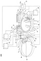
- FIG. 1 is a perspective view of the automatic analyzer of this embodiment.
- the automatic analyzer 1000 is a device for dispensing a sample and a reagent into a reaction vessel 2 and reacting them, and measuring the reacted liquid, which is a reaction disk 1, a reagent disk 9, and a sample.
- Reaction vessels 2 are lined up on the circumference of the reaction disk 1.
- a sample transport mechanism 17 for moving the rack 16 on which the sample container 15 is placed is installed near the reaction disk 1.
- a sample dispensing mechanism 11 that can rotate and move up and down is installed between the reaction disk 1 and the sample transport mechanism 17, and is provided with a sample probe 11a.
- a sample syringe 19 is connected to the sample probe 11a. The sample probe 11a moves while drawing an arc around the axis of rotation to dispense the sample from the sample container 15 to the reaction container 2.
- the reagent disk 9 has a structure in which a plurality of reagent bottles 10 containing reagents can be stored on the circumference. The details will be described later.
- This reagent disc 9 is kept cold and is covered with a cover provided with a suction port 111 (see FIG. 2).
- no device for example, RFID sensor or the like for obtaining information on the reagent in the reagent bottle 10 recorded on the RFID tag attached to the reagent bottle 10 is provided inside the reagent disk 9. It shall not be.
- a reagent dispensing mechanism 7 and 8 that can rotate and move up and down are installed between the reaction disk 1 and the reagent disk 9, and are equipped with reagent probes 7a and 8a, respectively.
- a reagent syringe 18 is connected to the reagent probes 7a and 8a. The reagent probes 7a and 8a move while drawing an arc around the axis of rotation, access the inside of the reagent disk 9 from the suction port 111, and dispense the reagent from the reagent bottle 10 to the reaction vessel 2.
- a cleaning mechanism 3, a light source 4a, a spectrophotometer 4, and stirring mechanisms 5 and 6 are further arranged around the reaction disk 1.
- a cleaning pump 20 is connected to the cleaning mechanism 3.
- Cleaning tanks 32, 33, 13, 30, and 31 are installed within the operating range of the reagent dispensing mechanism 7, 8, the sample dispensing mechanism 11, and the stirring mechanism 5, 6, respectively.
- the sample container 15 contains a sample, is placed on the rack 16, and is carried by the sample transport mechanism 17. Further, each mechanism is connected to the controller 21.
- the controller 21 is composed of a computer or the like, controls the operation of each mechanism in the automatic analyzer 1000, and performs arithmetic processing for obtaining the concentration of a predetermined component in the sample.
- the sample analysis process by the automatic analyzer 1000 as described above is generally executed in the following order.
- the sample in the sample container 15 placed on the rack 16 transported near the reaction disk 1 by the sample transfer mechanism 17 is subjected to the reaction container 2 on the reaction disk 1 by the sample probe 11a of the sample dispensing mechanism 11. Dispense into.
- the reagent used for analysis is dispensed from the reagent bottle 10 on the reagent disk 9 to the reaction vessel 2 into which the sample was previously dispensed by the reagent dispensing mechanisms 7 and 8.
- the stirring mechanism 5 stirs the mixed solution of the sample and the reagent in the reaction vessel 2.
- the light generated from the light source 4a is passed through the reaction vessel 2 containing the mixed solution after stirring, and the luminous intensity of the transmitted light is measured by the spectrophotometer 4.
- the luminous intensity measured by the spectrophotometer 4 is transmitted to the controller 21 via the A / D converter and the interface. Then, a calculation is performed by the controller 21, the concentration of a predetermined component in the sample is obtained, and the result is displayed on the display unit 21a or the like or stored in a storage unit (not shown).
- FIG. 2 is a diagram showing an outline of the autoloader mechanism 100.
- FIG. 3 is a schematic view of the gripper mechanism.
- FIG. 4 is a schematic view showing the relationship between the rib of the reagent disk or the reagent mounting portion and the reagent bottle.
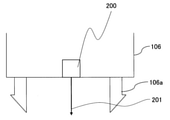
- FIG. 5 is a schematic view of a sensor provided in the gripper mechanism.
- a lid 112 is attached to the position of the reagent probe suction port of the reagent bottle 10 to seal the inside, and when the lid 112 is set in the automatic analyzer 1000, the lid 112 is removed and installed in the device. Is common.
- the autoloader mechanism 100 is arranged on the upper part of the reagent disc 9 and has a configuration as shown in FIG. In FIG. 2, the autoloader mechanism 100 includes a reagent loading unit 103, a reagent loading mechanism 102, a reagent transfer mechanism 101, a needle cleaning tank 108, a needle drying port 109, an RFID sensor 115, a support column 117, and a metal plate 118. Each of these mechanisms except the support column 117 is attached to one metal plate 118.
- the reagent loading unit 103 is a part for the operator to install the reagent bottle 10 when charging the reagent bottle 10 into the automatic analyzer 1000, and the reagent loading unit 103 is vertically oriented on FIG. 2 by the reagent loading mechanism 102. It works on.
- the operating range of the reagent loading unit 103 is set within the apparatus by fixing it on the metal plate 118 on which the autoloader mechanism 100 is arranged.
- the reagent loading unit 103 has a structure in which a plurality of reagent bottles 10 can be installed in a straight line, and is, for example, a tray having a plurality of reagent bottle slots for installing the reagent bottles 10.
- the reagent mounting unit 103 moves on the rail by the power of a motor or the like along a guide installed between the charging position of the reagent bottle 10 into the device and the standby position of the reagent mounting unit 103. It is configured to be able to.
- the reagent transfer mechanism 101 is a mechanism for transporting the reagent bottle 10 installed in the reagent loading unit 103 into the reagent disk 9, or installing the reagent bottle 10 in the reagent disk 9 in the reagent loading unit 103.
- the reagent transfer mechanism 101 includes a gripper mechanism 106 for gripping the reagent bottle 10, a lid opening mechanism 104 for making a notch-shaped hole in the lid 112 of the reagent bottle 10, and a vertical drive motor 132 for moving the lid opening mechanism 104 up and down. Further, the horizontal drive motor 131 for driving the gripper mechanism 106 and the lid opening mechanism 104 in the left-right direction on FIG. 2 is a component.
- the reagent transfer mechanism 101 operates in the left-right direction on FIG. 2 between the position of the reagent mounting portion 103 in FIG. 2 and the position of the opening / closing cover 113. That is, the reagent loading portion 103 moves in the vertical direction on FIG. 2, and the reagent transport mechanism 101 operates in the horizontal direction on FIG. 2, so that the operating directions are orthogonal to each other. Further, in the reagent transport mechanism 101, a position where the reagent bottle 10 is gripped by the gripper mechanism 106 and a position where the reagent bottle 10 is carried in and out of the reagent disk 9 are arranged linearly.
- the lid opening mechanism 104 is provided with a needle 105 for making a notch in the lid 112 of the reagent bottle 10.
- the needle 105 is washed after making a notch in the lid 112 in the needle washing tank 108 arranged parallel to the operating direction of the reagent transporting mechanism 101, and the reagent is transported in the next step.
- the washing water is removed by the needle drying port 109 arranged parallel to the operating direction of the mechanism 101.
- the needle cleaning tank 108 and the needle drying port 109 are arranged parallel to the operating direction of the reagent transport mechanism 101.
- the gripper mechanism 106 has a hooking claw 106a for gripping the reagent bottle 10, and the hooking claw 106a is hooked on the notch portion of the reagent bottle 10 to grip the reagent bottle 10. do.
- the opening / closing cover 113 is a cover for preventing the cold air inside the cooled reagent disk 9 from escaping, and is normally in a closed state.
- the opening / closing cover 113 opens, and operates so that the reagent bottle 10 can be carried in and out of the reagent disc 9.
- the RFID sensor 115 is arranged on the operation path of the reagent mounting unit 103, and obtains the information of the reagent in the reagent bottle 10 recorded on the RFID tag attached to the reagent bottle 10.
- the reagent information is information such as the type and filling amount of the reagent contained in the reagent bottle. Further, instead of the RFID sensor 115, a mechanism capable of reading a bar code and reading reagent information such as a bar code reader can be provided.
- the operator wants to carry the new reagent bottle 10 into the reagent disk 9 of the device, first press the button switch (not shown) of the device for the first time.
- the device recognizes that the first press of the button switch has been performed by the operator.
- the reagent loading mechanism 102 operates, the reagent loading unit 103 starts to move from the standby position, and moves to the front of the device (lower side in FIG. 2).
- the operator After the reagent loading unit 103 arrives in front of the device, the operator installs the reagent bottle 10 in the reagent loading unit 103. After installing the required number of reagent bottles 10 in the reagent loading unit 103, the operator presses the button switch again.
- the reagent information is read by the RFID sensor 115 mounted on the autoloader mechanism 100.
- the reagent information is read, it is displayed on the display unit 21a that the reagent information is provisionally registered.
- the reagent mounting unit 103 moves to the lower position of the lid opening mechanism 104.
- the lid opening mechanism 104 descends toward the lid 112 of the reagent bottle 10, and the needle 105 opens a notch in the lid 112 to the extent that the reagent probes 7a and 8a can be inserted.
- the lid opening mechanism 104 rises, and the reagent transfer mechanism 101 moves to the position of the needle cleaning tank 108 to wash the needle 105, and cleans the needle 105. After that, it moves to the needle drying port 109 and the needle 105 is dried.
- the reagent loading mechanism 102 operates the reagent loading unit 103 to move the notched reagent bottle 10 to the lower position of the gripper mechanism 106. After that, the gripper mechanism 106 is lowered to grab the reagent bottle 10, and then the open / close cover 113 is opened. After that, as the gripper mechanism 106 rises, it moves to the position of the open opening / closing cover 113, and carries in the reagent bottle 10 carried to the position of the empty reagent disk 9. After carrying in, the gripper mechanism 106 is returned to the position of the reagent mounting portion 103 again.
- the opening / closing cover 113 When the opening / closing cover 113 is normally closed, it is recognized that the reagent bottle 10 is normally installed on the reagent disk 9, and the registration of the reagent information is completed. At this time, the display unit 21a attached to the apparatus displays that the reagent information has been fully registered from the provisional registration state.
- the above is the reading of the reagent information from the installation of the reagent bottle 10 in the autoloader mechanism 100, the operation of drilling the lid 112 of the reagent bottle 10, the operation of carrying in the reagent disk 9, and the registration of the reagent information.
- the reagent bottle 10 is carried out according to the following flow.
- the carry-out timing of the reagent bottle 10 may be carried out even during the analysis after the completion of the final dispensing of the reagent dispensing mechanisms 7 and 8 or after the output of the analysis result.
- the controller 21 opens the open / close cover 113. Further, the reagent transfer mechanism 101 moves to the position of the open / close cover 113. Next, the empty reagent bottle 10 is gripped by the gripper mechanism 106. In parallel with this, the reagent loading unit 103 moves from the standby position, and the empty reagent bottle slot of the reagent mounting unit 103 stops at a position below the orbit of the gripper mechanism 106.
- the reagent transfer mechanism 101 moves to the position of the reagent loading mechanism 102 while holding the empty reagent bottle 10 by the gripper mechanism 106. In parallel with this, the opening / closing cover 113 is closed. At that time, it is determined that the reagent bottle 10 has been normally carried out, and the display unit 21a indicates that the registered reagent information has been deleted. After that, the empty reagent bottle 10 is placed in the empty reagent bottle slot of the reagent loading portion 103 by the gripper mechanism 106. After that, the reagent loading mechanism 102 returns to the standby position.
- the display unit 21a or the like notifies the operator that the empty reagent bottle 10 can be taken out.
- the operator Upon receiving this notification, the operator takes out the empty reagent bottle 10 out of the device.
- the reagent disk 9 is used. Provide one or several empty reagent slots for the number that can be installed. Then, the reagent bottle 10 installed in the reagent mounting section 103 is carried into the reagent disk 9 without making a cut in the lid 112, and the empty reagent bottle 10 is grasped by the gripper mechanism 106 and placed on the reagent mounting section 103. After that, the operator carries out the empty reagent bottle 10. After carrying out, the reagent bottle 10 without a notch installed in the reagent disk 9 can be returned to the empty reagent slot again. Similar operation is possible if an empty slot is provided in the reagent mounting portion 103.
- the reagent bottle 10 When the position of the reagent bottle 10 is displaced with respect to the gripper mechanism 106 in the operation of the reagent disk 9 and the reagent mounting portion 103, the reagent bottle 10 is gripped by the gripper mechanism 106 at a position different from the originally gripped portion. There is a pity that stable grip cannot be performed. In addition, when the deviation becomes large, in the worst case, it may not be possible to grasp it.
- the lid 112 is operated to open a notch to the extent that the reagent probes 7a and 8a can be inserted into the lid 112 with the needle 105.
- the notch is opened at a position deviated from the center position of the reagent, and there is a pity that an unnecessary load is applied to the reagent probes 7a and 8a at the time of suction.
- the notch cannot be opened, or the notch is made in an unnecessary part and the contact between the reagent and the outside air becomes large, so that the deterioration of the reagent may progress. There is.
- the reagent disk 9 is provided with a rib 300 for partitioning the reagent bottle 10 on the installation surface 500 of the reagent disk 9, and the reagent mounting portion 103 also partitions the reagent bottle 10 on the installation surface 600.
- Ribs 400 are provided.
- the gap 900 between the ribs 300, 400 and the reagent bottle 10 shown in FIG. 4 is set to 0.5 mm or less in consideration of the above-mentioned risk.
- the gripper mechanism is used when the positional relationship between the reagent disk 9 and the gripper mechanism 106 and the reagent mounting portion 103 and the gripper mechanism 106 is broken.
- the reagent bottle 10 may run on the rib 300. Further, there is a possibility that the reagent bottle 10 rides on the rib 400 in the same operation with respect to the reagent mounting portion 103.
- a sensor (light source 210 + detector 211) is provided in the gripper mechanism 106, and the rib 300 provided in the reagent disk 9 or the reagent mounting portion 103 is provided.
- the idea was to detect the provided rib 400 and automatically adjust the positions of the reagent disk 9 and the gripper mechanism 106 or the reagent mounting portion 103 and the gripper mechanism 106.
- the reference member is not limited to the ribs 300 and 400, and a marker or a concave-convex shape for installing a reagent can be used, and the sensor is not limited to the reflective type, and a camera, a laser displacement meter, or the like can be used.
- the members and sensors that serve as the standard for the above, the idea was that any type other than the originally provided configuration could be used, either a stationary type or a removable type.
- the senor 200 is provided in the gripper mechanism 106 of the reagent transfer mechanism 101.
- the sensor 200 includes a light source 210 and a detector 211, and by using triangulation, the distance from the sensor 200 to the target surface can be grasped.
- the controller 21 adjusts the transfer parameters of the reagent transfer mechanism 101 based on the positions of the ribs 300 and ribs 400 detected by the reflection type sensor 200.
- the sensor 200 may be incorporated in the gripper mechanism 106 or may be removable.
- the removable structure is not particularly limited, and various known means can be adopted. This makes it very easy to apply the technique of the present invention to an existing device.
- the senor 200 is performed on the assumption that the optical axis 201 is located at the center of the gripper mechanism 106.
- the senor 200 may be located anywhere in the gripper mechanism 106, but in that case, it is necessary to further reflect the distance from the optical axis 201 of the sensor 200 to the center of the gripper mechanism 106 as a correction value in the following description. be.
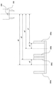
- FIG. 6 is a schematic view showing the ribs of the reagent disk and the reagent mounting portion.
- FIG. 7 is a schematic view showing a cross-sectional view of the reagent disk and the gripper mechanism in the X direction, and
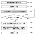
- FIG. 8 is a flowchart for automatically adjusting the position of the gripper mechanism (X direction) with respect to the reagent disk.
- FIG. 9 is a schematic view showing a cross-sectional view of the reagent disk and the gripper mechanism in the Y direction, and FIG.
- FIG. 10 is a flowchart for automatically adjusting the position of the reagent disk (in the ⁇ direction) with respect to the gripper mechanism.
- FIG. 11 is a schematic view showing a cross-sectional view of the reagent disk and the gripper mechanism in the Z direction
- FIG. 12 is a flowchart for automatically adjusting the position of the gripper mechanism (Z direction) with respect to the reagent disk.
- each configuration on the installation surface 500 of the reagent disk 9 and the installation surface 600 of the reagent mounting portion 103 will be described with reference to FIG.
- a plurality of reagent bottles 10 can be placed concentrically, and ribs 300a and 300b for setting installation positions from the inner peripheral side to the inner peripheral side in the radial direction.
- ribs 300c and 300d for setting the installation position on the outer peripheral side are provided.
- ribs 300e and 300f are provided on the inner peripheral side
- ribs 300g and 300h are provided on the outer peripheral side, respectively.
- the installation position on the outer peripheral side is set by 300c, 300g, 300d, and 300h.
- the reagent mounting unit 103 is configured so that five reagent bottles 10 can be mounted in FIG. 6, and ribs 400a, 400b, 400c, 400d, and 400e are provided from the lower middle side of FIG. A wall having a height higher than that of the rib is provided on the back side of the rib 400e. Ribs 400f and 400g are provided on the side surface sides of these ribs 400a, 400b, 400c, 400d and 400e.
- the moving direction of the reagent mounting portion 103 is the X direction
- the moving direction of the gripper mechanism 106 is the Y direction
- the vertical direction of the paper surface of FIG. 6 is the Z direction.
- the direction of the rotation component on the XY plane is the ⁇ direction.
- step S120 the reagent disc 9 and the gripper mechanism 106 are moved to the standby position to start the operation.
- step S121 open the open / close cover 113
- step S121 open the open / close cover 113
- step S121 open the open / close cover 113
- the gripper mechanism 106 is operated in the direction of the opening / closing cover 113.
- the horizontal drive motor 131 of the gripper mechanism 106 is a stepping motor
- the horizontal drive motor 131 is driven by one pulse (step S122), and after the movement, the sensor 200 is used to confirm the presence / absence of detection of the rib 300a. (Step S123).
- step S122 If it is not detected, the process is returned to step S122, and the horizontal drive motor 131 is driven by one pulse again.
- the distance a1 from the standby position of the gripper mechanism 106 to the rib 300a is grasped and managed from the total number of pulses given when the controller 21 is detected (step S124).
- the drive motor When the drive motor is equipped with an encoder capable of grasping the rotation speed and the position, it is possible to grasp the above-mentioned distances a1 and a2 by operating the drive motor at a constant speed. Compared to stepping motors, it is possible to shorten the time required to grasp each distance.
- the center position between the rib 300a and the rib 300b and the center position a3 between the rib 300c and the rib 300d which are the installation positions of the reagent bottle 10, are fixed values and can be grasped from the processes of steps S120 to S124.
- the distance a5 obtained by adding the distance a3 to the distance a1 and the distance a6 obtained by adding the distance a3 to the distance a2 are the stop positions of the gripper mechanism 106 with respect to the reagent disk 9. Therefore, the controller 21 sets the stop positions a5 and a6 in the X direction with respect to the reagent disk 9 of the gripper mechanism 106 (step S125), and closes the open / close cover 113 (step S126).
- step S130 Immediately after the adjustment of the stop positions a5 and a6 described above is completed, or after a predetermined time has elapsed, the controller 21 again puts the reagent disk 9 and the gripper mechanism 106 into the standby position as shown in FIGS. 9 and 10. Move (step S130).
- step S131 the open / close cover 113 is opened (step S131).
- the gripper mechanism 106 is moved to the reagent bottle 10 installation position a5 on the inner peripheral side of the reagent disc 9 (step S132).
- the position to be moved at this time is the one set in step S125.
- the reagent disk drive motor (not shown) is driven by one pulse (step S133), and after rotation, the presence or absence of detection of the rib 300e is confirmed using the sensor 200 (step S134).
- the reagent disk 9 and the reagent disk drive motor are connected by a gear or a belt, but in consideration of backlash in the gear or the belt, the rotation direction of the reagent disk 9 and the reagent disk drive motor described above is the reagent disk. 9 and the direction of movement of the reagent disk drive motor to the standby position are the same.
- step S133 If the sensor 200 does not detect it, the process is returned to step S133, and the reagent disk drive motor is driven by one pulse.
- the distance b1 from the standby position of the reagent disk 9 to the rib 300e is grasped and managed from the total number of pulses given at the time of detection (step S135).
- steps S131 to S135 By applying the operations of steps S131 to S135 to the reagent bottle 10 installation position a6 on the outer peripheral side of the reagent disk 9, it is possible to grasp the distance b2 from the standby position of the reagent disk 9 to the rib 300 g.
- the drive motor When the drive motor is equipped with an encoder capable of grasping the rotation speed and the position, it is possible to grasp the above-mentioned distances b1 and b2 by operating the drive motor at a constant speed. Compared to stepping motors, it is possible to shorten the time required to grasp each distance.
- the center positions b3 between the ribs 300e and 300f and the center positions b3 between the ribs 300g and 300h, which are the installation positions of the reagent bottle 10, are fixed values.
- the distance b5 obtained by subtracting the distance b3 from the distance b1 and the distance b6 obtained by subtracting the distance b3 from the distance b2 are the stop positions of the reagent disk 9 with respect to the gripper mechanism 106. Therefore, the controller 21 sets the stop positions b5 and b6 in the ⁇ direction with respect to the reagent disk 9 of the gripper mechanism 106 (step S136). After that, the opening / closing cover 113 is closed (step S137).
- step S140 the reagent disc 9 and the gripper mechanism 106 are moved to the standby position, and the operation is started (step S140).
- step S141 the open / close cover 113 is opened (step S141).
- the gripper mechanism 106 is moved to the stop position a5 set in step S125 described above (step S142), and the reagent disk 9 is horizontally moved to the stop position b5 set in step S136 described above (step). S143).
- the stop position of the gripper mechanism 106 may be a6, and the stop position of the reagent disc 9 may be b6.
- step S144 the distance c1 from the standby position of the gripper mechanism 106 in the vertical direction to the reagent bottle installation surface 500 of the reagent disk 9 is grasped.
- the grasped distance is managed by the controller 21 (step S145).
- c2 is defined as the height obtained by adding the height of the reagent bottle 10 and the cushioning amount of the gripper mechanism 106 required for hooking the hooking claw 106a to the notch portion of the reagent bottle 10.
- the height c3 of the gripper mechanism 106 when installing the reagent bottle 10 on the disk 9 and when gripping the reagent bottle 10 from the reagent disk 9 is a value obtained by subtracting c2 from the distance c1 acquired from the above sensor, and c3 is the gripper mechanism.
- This is the stop position of 106 in the vertical direction. Therefore, the controller 21 sets the stop position c3 of the gripper mechanism 106 in the Z direction (step S146). After that, the opening / closing cover 113 is closed (step S147).
- FIG. 13 is a schematic view showing a cross-sectional view of the reagent mounting portion and the gripper mechanism in the Y direction
- FIG. 14 is a flowchart for automatically adjusting the position of the reagent mounting portion (Y direction) with respect to the gripper mechanism.
- FIG. 15 is a schematic view showing a cross-sectional view of the reagent mounting portion and the gripper mechanism in the X direction
- FIG. 16 is a flowchart for automatically adjusting the position of the gripper mechanism (X direction) with respect to the reagent mounting portion.
- FIG. 17 is a schematic view showing a cross-sectional view of the reagent mounting portion and the gripper mechanism in the Z direction
- FIG. 18 is a flowchart for automatically adjusting the position of the gripper mechanism (Z direction) with respect to the reagent mounting portion.
- step S150 the reagent mounting portion 103 and the gripper mechanism 106 are moved to the standby position, and the operation is started (step S150).
- the gripper mechanism 106 is operated in the direction of the opening / closing cover 113 and stopped on the orbit of the reagent mounting portion 103 (step S151).
- the stop position of the gripper mechanism 106 is a temporary position where the adjustment value is not reflected.
- step S152 when the drive motor 134 of the reagent mounting unit 103 is a stepping motor, the drive motor 134 is driven by one pulse to move the reagent mounting unit 103 toward the device (step S152), and after the movement, the sensor 200 is used. , Confirm the presence / absence of detection of the rib 400a (step S153).
- step S152 If the sensor 200 does not detect it, the process returns to step S152 and the drive motor 134 is driven by one pulse.
- the controller 21 grasps and manages the distance d1 from the standby position of the reagent mounting unit 103 to the rib 400a from the total number of pulses given at the time of detection (step S154).
- the drive motor When the drive motor is equipped with an encoder capable of grasping the rotation speed and the position, it is possible to grasp the above-mentioned distances d1 to d5 by operating the drive motor at a constant speed. Compared to stepping motors, it is possible to shorten the time required to grasp each distance.
- the center distance d6 between the rib 400a and the rib 400b which is the installation position of the reagent bottle 10, is a fixed value.
- the distance d7 obtained by adding the distance d6 to the distance d1 grasped from the above-mentioned operation is the stop position of the reagent mounting position of the reagent mounting unit 103 with respect to the gripper mechanism 106. Therefore, the controller 21 sets the stop position d7 in the Y direction of the reagent mounting unit 103 (step S155).
- step S160 After the adjustment of the stop position of the reagent mounting unit 103 in the Y direction is completed, the reagent mounting unit 103 and the gripper mechanism 106 are moved to the standby position as shown in FIGS. 15 and 16 (step S160).
- step S161 the reagent mounting position of the reagent loading unit 103 is moved to the above-mentioned stop position d7 (step S161).
- step S162 the horizontal drive motor 131 of the gripper mechanism 106 is driven by one pulse to move the gripper mechanism 106 toward the open / close cover 113 (step S162).
- step S163 After moving, the presence or absence of detection of the rib 400f is confirmed using the sensor 200 (step S163).
- step S162 If the sensor 200 does not detect it, the process returns to step S162 and the horizontal drive motor 131 is driven by one pulse.
- the controller 21 grasps and manages the distance e1 from the standby position of the gripper mechanism 106 to the rib 400f from the total number of pulses given at the time of detection (step S164).
- the drive motor When the drive motor is equipped with an encoder capable of grasping the rotation speed and the position, the distance e1 can be grasped by operating the drive motor at a constant speed, and the stepping motor can be grasped. It is possible to shorten the time required to grasp each distance.
- the center distance e2 between the rib 400f and 400 g which is the installation position of the reagent bottle 10, is a fixed value.
- the distance e3 obtained by adding the distance e2 to the distance e1 grasped from the above-mentioned operation is the stop position of the gripper mechanism 106 with respect to the reagent mounting portion 103. Therefore, the controller 21 defines the stop position e3 in the X direction with respect to the reagent mounting portion 103 of the gripper mechanism 106 (step S165).
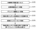
- step S170 the reagent mounting portion 103 and the gripper mechanism 106 are moved to the standby position, and the operation is started (step S170).
- the reagent mounting unit 103 is moved to the stop position d7 set in step S155 described above (step S171), and the gripper mechanism 106 is horizontally moved to the stop position e3 set in step S165 described above (step). S172).
- step S173 the distance f1 from the standby position of the gripper mechanism 106 in the vertical direction to the reagent bottle mounting surface 600 of the reagent mounting unit 103 is grasped.
- the grasped distance is managed by the controller 21 (step S174).
- f2 is defined as the height obtained by adding the height of the reagent bottle 10 and the cushioning amount of the gripper mechanism 106 required for hooking the hooking claw 106a to the notch of the reagent bottle 10
- the height f3 of the gripper mechanism 106 when the reagent bottle 10 is installed on the mounting unit 103 and when the reagent bottle 10 is gripped from the reagent mounting unit 103 is a value obtained by subtracting f2 from the distance f1 acquired from the above sensor, and f3 is This is the stop position of the gripper mechanism 106 in the vertical direction. Therefore, the controller 21 sets the stop position f3 in the Z direction of the gripper mechanism 106 (step S175).
- the lid 112 attached to the reagent bottle 10, the needle cleaning tank 108, and the needle drying port 109 may be provided with a taper. Further, the needle 105 may also be provided with a taper.
- the horizontal direction of the needle cleaning tank 108 and the needle drying port 109 is not essential, but may be performed.
- the needle 105 may be provided with a cushioning material. Therefore, even if some misalignment of the lid 112, the needle cleaning tank 108, and the needle drying port 109 with respect to the needle 105 occurs in the vertical direction, it can be corrected.
- the position adjustment of the mechanism 104 is not essential, but may be performed.
- FIG. 19 is a schematic view showing a cross-sectional view of the reagent disk and the gripper mechanism in the Z direction
- FIG. 20 is a flowchart showing an operation of confirming the height and inclination of the reagent bottle mounting surface 500 of the reagent disk using the gripper mechanism. be.
- the reagent disc 9 also has the problems described below.
- the reagent disc 9 is generally manufactured by integral molding or by dividing parts, but since it has a large shape and the support point is only the center of rotation of the reagent disc 9, it is subject to gravity. As a result, it is conceivable that the reagent bottle installation surface of the reagent disk 9 will be distorted.
- Distortion of the reagent bottle mounting surface 500 of the reagent disk 9 shown in FIG. 19 may affect the reagent dispensing performance of the reagent probes 7a and 8a.
- the reagent probes 7a and 8a move while drawing an arc around the rotation axis, access the inside of the reagent disk 9 from the suction port 111, and dispense the reagent from the reagent bottle 10 to the reaction vessel 2. conduct.
- the distortion of the reagent disk 9 causes a variation in the height of each reagent bottle mounting surface 500, and even if the same reagent bottle 10 is used, the liquid level of each reagent bottle 10 as seen from the reagent probes 7a and 8a There is a difference in height, which may affect the reagent dispensing performance. Further, if the reagent bottle installation surface 500 is tilted, the reagent probes 7a and 8a cannot be inserted into the notch of the lid 112, which may lead to bending of the probe and stoppage of the device.
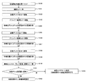
- the reagent disc 9 and the gripper mechanism 106 are moved to the standby position, and the adjustment is started (step S180).
- step S181 the open / close cover 113 is opened (step S181).
- the reagent disc 9 is moved to b5 (step S182), and the gripper mechanism 106 is moved to a7 (step S183).
- the sensor 200 is used to grasp the distance g1 from the gripper mechanism 106 to the reagent bottle installation surface 500 (step S184).
- the reagent disk 9 is moved from b5 to the position b7 (omitted for convenience of illustration) rotated by a very small amount (for example, one step) (step S185), and the gripper mechanism 106 is moved to a8 (step S186). ..
- the sensor 200 is used to grasp the distance g2 from the gripper mechanism 106 to the reagent bottle installation surface 500 (step S187).
- the reagent disk 9 is moved from b5 to the position b8 (omitted for convenience of illustration) rotated by a very small amount (for example, -1 step) (step S188).
- the sensor 200 is used to grasp the distance g3 from the gripper mechanism 106 to the reagent bottle installation surface 500 (step S189).
- the distances grasped in steps S184, S187, and S189 are managed by the controller 21, and the open / close cover 113 is closed (step S190).
- the reagent disk 9 does not have the reagent bottle 10 for the above-mentioned operation.
- the range is narrowed down to a place where the reagent bottle 10 is not installed, and the reagent bottle installation surface. It is possible to detect whether there is any abnormality in the height and inclination of the.
- the height and inclination of the reagent bottle installation surface 500 are grasped, and it is determined whether or not there is an abnormality in the height and inclination of the reagent bottle installation surface 500 (step). S191). For example, it is determined based on conditions such as whether or not the differences between the distances g1, g2, and g3 are all less than a predetermined value.
- step S192 when it is determined that there is no abnormality, the reagent bottle installation surface 500 is left usable (step S192), and the process is terminated.
- the data such as the horizontal position, the vertical position, and the height and inclination of the reagent bottle mounting surface of the reagent disk 9 with respect to the gripper mechanism 106 of the reagent transfer mechanism 101 with respect to the reagent disk 9 or the reagent mounting unit 103 obtained from the above are obtained from the controller 21. Manage at.
- the controller 21 determines whether or not there is an abnormality or a failure state of the reagent loading unit 103, the reagent disk 9, or the reagent transport mechanism 101 from the acquired data of the change with time of the distance, and when the controller 21 deviates from the reference range. If an abnormality is found, such as exceeding the threshold value, an alarm is issued.
- controller 21 predicts the time when the reagent loading unit 103, the reagent disk 9, or the reagent transport mechanism 101 is determined to be in an abnormal or failed state based on the change over time, and issues an alarm. can.
- the stop position of the reagent mounting unit 103, the reagent disk 9, and the reagent transfer mechanism 101 is expected to change due to deterioration over time, so the life of each component is predicted from the transition of the acquired position data. And an alarm can be issued.
- the device can be used as usual.
- an alarm is set to recommend replacement of the corresponding part, and the device can be used as usual.
- an alarm is set to stop the registration and deletion function of the reagent, and the function of the autoloader mechanism 100 is stopped.
- the controller 21 stops only the operation of the reagent transfer mechanism 101, and an alarm indicating that the transfer of the reagent bottle 10 by the reagent transfer mechanism 101 is stopped. Can be triggered. At this time, the other mechanisms can be operated as usual, and analysis is possible as long as the amount of the reagent in the installed reagent bottle 10 is not exhausted.
- the check function of each mechanism described above is an example, but by providing the check function described above, it is possible to detect an abnormality in the device and prevent an abnormal state such as a device stop during analysis.
- the reagent bottle 10 is basically installed only at the time of loading and unloading, no special consideration is required as compared with the reagent disk 9.
- the rib 300 provided on the reagent disk 9, the rib 400 provided on the reagent mounting portion 103, and the rib 300 provided on the reagent transport mechanism 101 Since it is provided with a reflection type sensor 200 for detecting 400 and a controller 21 for adjusting the transfer parameters of the reagent transfer mechanism 101 based on the positions of the ribs 300 and 400 detected by the reflection type sensor 200. It is possible to automatically grasp the relative positional relationship (horizontal / height) between the reagent disk 9 and the mechanism related to the loading / unloading of the reagent bottle on the device side, and reflect the adjustment value to each mechanism unit.
- the reagent bottle 10 can be normally installed on the reagent disc 9 more stably than in the conventional case.
- the reflection type sensor 200 can adjust the horizontal movement parameter of the reagent transfer mechanism 101 by measuring the distance from the standby position in the horizontal direction of the reagent transfer mechanism 101 to the ribs 300 and 400.
- the horizontal movement amount of the reagent transfer mechanism 101 based on the distance from the standby position to the ribs 300 and 400, the horizontal movement of the reagent transfer mechanism 101 without performing manual maintenance or the like is performed.
- the distance can be adjusted, and stable reagent bottle 10 can be transported.
- the reflection type sensor 200 can adjust the movement parameter of the reagent transfer mechanism 101 in the vertical direction by measuring the distance from the standby position of the reagent transfer mechanism 101 in the vertical direction to the ribs 300 and 400.
- the vertical movement of the reagent transfer mechanism 101 can be performed without performing manual maintenance or the like.
- the distance can be adjusted, and stable reagent bottle 10 can be transported.
- the position shift due to deterioration over time can be automatically grasped, and measures such as reflecting the shift amount in the adjustment value can be taken before a malfunction such as a failure occurs. Therefore, it is possible to suppress the abnormal stoppage of the device during the analysis as compared with the conventional case.
- the reagent loading unit 103, the reagent disk 9, or the reagent transport mechanism 101 is determined to be in an abnormal or failed state based on the change over time, and issuing an alarm, a failure or the like can be detected earlier. You can take measures before a problem occurs.
- the height and inclination of the installation surface 500 are obtained from the time course of the distance from the standby position to the rib 300 at a plurality of places, and the abnormality or failure state of the reagent disk 9 is determined from the inclination, so that the reagent disk 9 itself It is possible to automatically determine the presence or absence of aging deterioration.
- the reagent disk 9 itself becomes unusable by issuing an alarm by predicting the time when the reagent disk 9 is determined to be in an abnormal or failed state from the change over time. It will be easier to suppress than before.
- the reagent bottle 10 to the reagent discs 9 other than the reagent discs 9 determined to have an abnormality is added.
- the analysis is completely stopped only because the reagent disk 9 having an abnormality exists. It can be suppressed.
- an automatic analyzer provided with an autoloader mechanism 100 for automatically carrying the reagent bottle 10 into the reagent disk 9 has been described as an example, but the autoloader mechanism 100 is not necessarily in the form shown in FIG. It is not necessary to have the present invention, and the present invention can be applied as long as it has at least one location where the drive shafts intersect.
- the reagent disk 9 or the reagent mounting unit 103 is not the gripper mechanism 106 but the reagent disk 9 or the reagent mounting unit 103.
- a sensor 200 is provided on the side, and the transfer parameters of the reagent transfer mechanism 101 can be controlled based on the position of the reference member provided in the reagent transfer mechanism 101. Even in such an embodiment, the same effect as that of the above-described embodiment can be obtained.
- the reference member is the ribs 300 and 400 for partitioning the reagent bottle 10
- a marker provided on the reagent transfer mechanism 101, the reagent disk 9, or the reagent mounting portion 103 is described.
- at least one of the concave shape and the convex shape indicating the position where the reagent bottle 10 is installed can be used as the reference member, and the same effect can be obtained.
- the reference member is a marker, it can be made removable. If it is removable in this way, the present invention can be easily applied to existing devices, and it is only necessary to attach it when adjustment is required, so that it may interfere with the operation during normal analysis operation. It can be assumed that there is almost no sex.
- the reflection type sensor 200 in which the sensor is composed of the light source 210 and the detector 211 that detects the light emitted from the light source 210 and reflected by the reference member has been described.
- the sensor is a reflection type sensor 200. Instead, it can be at least one of a camera that captures an image of the reference member and a laser displacement meter that measures the distance to the reference member.
- Reagent transfer mechanism (reagent transfer unit) 102 ... Reagent mounting mechanism 103 ... Reagent mounting part 104 ... Lid opening mechanism 105 ... Needle 106 ... Gripper mechanism 106a ... Hooking claw 108 ... Needle cleaning tank 109 ... Needle drying port 111 ... Suction port 112 ... Lid 113 ... Opening / closing cover 115 ... RFID sensor 117 ... Support 118 ... Metal plate 131 ... Horizontal drive motor 132 ... Vertical drive motor 134 ... Drive motor 200 ... Sensor 201 ... Optical axis 210 ... Light source 211 ... Detector 300, 300a, 300b, 300c, 300d, 300e, 300f , 300g, 300hi ...
- Rib (reagent disc) 400, 400a, 400b, 400c, 400d, 400e, 400f, 400g ... Rib (reagent mounting part) 500 ... Reagent bottle installation surface (reagent disc) 600 . Reagent bottle installation surface (reagent mounting part) 900 ... Gap between rib and reagent bottle 1000 ... Automatic analyzer
Abstract
This automatic analysis device comprises: ribs 300 provided to a reagent disc 9, or ribs 400 provided to a reagent loading part 103; a reflective sensor 200 that is provided to a reagent transport mechanism 101 and detects the ribs 300, 400; and a controller 21 that adjusts the transport parameters of the reagent transport mechanism 101 on the basis of the positions of the ribs 300, 400 that are detected by the reflective sensor 200. Thus provided is an automatic analysis device that can automatically load and unload reagent bottles, and can reduce the burden on an operator and suppress stoppages of the device in comparison to conventional devices.
Description
血液,尿などの生体サンプル(以下「検体」と記載)の分析を行う自動分析装置に関し、特に、より多くの分析項目の分析を可能とする自動分析装置に関する。
Regarding an automatic analyzer that analyzes biological samples such as blood and urine (hereinafter referred to as "sample"), in particular, an automatic analyzer that enables analysis of more analysis items.
試薬登録、試薬交換等の作業によるオペレータの負担を軽減すると共に、分析中に試薬不足を発生させず、分析中断を最小化する自動分析装置の一例として、特許文献1には、複数の反応容器に検体と試薬を各々分注して反応させ、反応した液体を測定する自動分析装置において、反応に使用する試薬を保管する第1の試薬保管手段と、試薬を補助用に保管する第2の試薬保管手段と、第2の試薬保管手段から第1の試薬保管手段に試薬を搬送する試薬搬送手段と、を備えたことが記載されている。
As an example of an automatic analyzer that reduces the burden on the operator due to operations such as reagent registration and reagent exchange, does not cause reagent shortage during analysis, and minimizes analysis interruption, Patent Document 1 describes a plurality of reaction vessels. In an automatic analyzer that dispenses and reacts a sample and a reagent to each other and measures the reacted liquid, a first reagent storage means for storing the reagent used for the reaction and a second reagent storage for auxiliary use. It is described that the reagent storage means and the reagent transfer means for transporting the reagent from the second reagent storage means to the first reagent storage means are provided.
生化学自動分析装置や免疫自動分析装置で使用する試薬は、オペレーターが試薬ディスクに試薬ボトルを設置してから、装置内に設置されたRFIDリーダやバーコードリーダなどの読み取機構で試薬ボトルに貼付けされている識別情報を取得することで管理するのが一般的である。
Reagents used in biochemical automatic analyzers and immunoassays are affixed to reagent bottles by a reading mechanism such as an RFID reader or barcode reader installed inside the device after the operator installs the reagent bottle on the reagent disk. It is generally managed by acquiring the identification information.
これに対し、近年、特許文献1に記載されたような、自動で試薬ボトルを搬入・搬出する機構を用いて試薬ディスク機構へ試薬ボトルを設置し、試薬の管理を行うことが知られている。
On the other hand, in recent years, it is known that a reagent bottle is installed in a reagent disk mechanism by using a mechanism for automatically loading and unloading a reagent bottle as described in Patent Document 1 to manage reagents. ..
特許文献1に記載されたような試薬ボトルの自動の搬入・搬出技術は、試薬登録や試薬交換等の作業によるオペレーターの負担を軽減すると共に、分析中の試薬不足を発生させず、分析中断を最小化する、との利点がある。
The automatic loading / unloading technology for reagent bottles as described in Patent Document 1 reduces the burden on the operator due to work such as reagent registration and reagent exchange, and does not cause a shortage of reagents during analysis, so analysis is interrupted. It has the advantage of being minimized.
ここで、近年の自動分析装置の分析速度の向上に伴い、試薬の消費量が多くなり、試薬ボトル交換のインターバルも短くなってきている。
Here, with the improvement of the analysis speed of the automatic analyzer in recent years, the consumption of reagents has increased and the interval of reagent bottle replacement has become shorter.
そのような中で試薬の管理を正確に行うためには、試薬ボトルが試薬ディスクに正常に設置する技術が重要となってくるが、試薬ボトル搬入・搬出機構および試薬ディスク機構の相対位置関係は、各部品の製作ばらつきなどにより一定とならない。そのため、製品ごとに機構部の調整を行う必要があり、調整作業者の大きな負担となっている。
Under such circumstances, in order to manage reagents accurately, the technology to normally install the reagent bottles on the reagent discs is important, but the relative positional relationship between the reagent bottle loading / unloading mechanism and the reagent disc mechanism is , It is not constant due to manufacturing variations of each part. Therefore, it is necessary to adjust the mechanical part for each product, which is a heavy burden on the adjustment worker.
また、摺動部の経年劣化により各機構の位置ずれが発生することが避けられないが、位置ずれが生じると試薬ボトルの設置異常となったり、最悪の場合は試薬ディスクの動作不良による装置の動作停止に陥る恐れがあることから、対策をとる必要がある。
In addition, it is inevitable that the misalignment of each mechanism will occur due to the deterioration of the sliding parts over time. Since there is a risk of operation stoppage, it is necessary to take measures.
本発明は、試薬ボトルを自動で搬出・搬入すること可能な自動分析装置において、従来に比べて作業者の負担を軽減するとともに装置の停止に陥ることを抑制することが可能な自動分析装置を提供する。
INDUSTRIAL APPLICABILITY The present invention is an automatic analyzer capable of automatically carrying in and out a reagent bottle, which can reduce the burden on the operator and prevent the device from stopping as compared with the conventional one. offer.
本発明は、上記課題を解決する手段を複数含んでいるが、その一例を挙げるならば、自動分析装置であって、検体と反応させる試薬を収容した試薬ボトルを保管する試薬保管部と、前記試薬ボトルを前記試薬保管部に搬送する試薬搬送部と、前記試薬保管部あるいは前記試薬搬送部に設けられている基準部材と、前記試薬保管部および前記試薬搬送部のうち前記基準部材が設けられていない側に設けられており、前記基準部材を検知するセンサと、前記センサにより検知された基準部材の位置に基づいて、前記試薬搬送部の搬送パラメータを調整する制御部と、を備えたことを特徴とする。
The present invention includes a plurality of means for solving the above problems, and one example thereof is an automatic analyzer, which is a reagent storage unit for storing a reagent bottle containing a reagent to be reacted with a sample, and the above-mentioned reagent storage unit. A reagent transport section for transporting a reagent bottle to the reagent storage section, a reference member provided in the reagent storage section or the reagent transport section, and the reference member among the reagent storage section and the reagent transport section are provided. It is provided on the side not provided, and is provided with a sensor for detecting the reference member and a control unit for adjusting the transfer parameters of the reagent transfer unit based on the position of the reference member detected by the sensor. It is characterized by.
本発明によれば、従来に比べて作業者の負担を軽減するとともに装置の停止に陥ることを抑制することができる。上記した以外の課題、構成および効果は、以下の実施例の説明により明らかにされる。
According to the present invention, it is possible to reduce the burden on the operator and prevent the device from stopping as compared with the conventional case. Issues, configurations and effects other than those mentioned above will be clarified by the description of the following examples.
本発明の自動分析装置の実施例について図1乃至図20を用いて説明する。なお、本明細書で用いる図面において、同一のまたは対応する構成要素には同一、または類似の符号を付け、これらの構成要素については繰り返しの説明を省略する場合がある。
Examples of the automatic analyzer of the present invention will be described with reference to FIGS. 1 to 20. In the drawings used in the present specification, the same or corresponding components may be designated by the same or similar reference numerals, and repeated description of these components may be omitted.
最初に、自動分析装置の全体構成について図1を用いて説明する。図1は本実施形態の自動分析装置の斜視図である。
First, the overall configuration of the automatic analyzer will be described with reference to FIG. FIG. 1 is a perspective view of the automatic analyzer of this embodiment.
図1において、自動分析装置1000は、検体と試薬を反応容器2に各々分注して反応させ、この反応させた液体を測定するための装置であって、反応ディスク1、試薬ディスク9、検体搬送機構17、試薬分注機構7,8、試薬用シリンジ18、サンプル分注機構11、検体用シリンジ19、洗浄機構3、光源4a、分光光度計4、撹拌機構5,6、洗浄用ポンプ20、洗浄槽13,30,31,32,33、コントローラ21、オートローダー機構100(図2参照)を備えている。
In FIG. 1, the automatic analyzer 1000 is a device for dispensing a sample and a reagent into a reaction vessel 2 and reacting them, and measuring the reacted liquid, which is a reaction disk 1, a reagent disk 9, and a sample. Transfer mechanism 17, reagent dispensing mechanism 7, 8, reagent syringe 18, sample dispensing mechanism 11, sample syringe 19, cleaning mechanism 3, light source 4a, spectrophotometer 4, stirring mechanism 5, 6, cleaning pump 20 , A cleaning tank 13, 30, 31, 32, 33, a controller 21, and an autoloader mechanism 100 (see FIG. 2).
反応ディスク1には反応容器2が円周上に並んでいる。反応ディスク1の近くには検体容器15を載せたラック16を移動する検体搬送機構17が設置されている。
Reaction vessels 2 are lined up on the circumference of the reaction disk 1. A sample transport mechanism 17 for moving the rack 16 on which the sample container 15 is placed is installed near the reaction disk 1.
反応ディスク1と検体搬送機構17の間には、回転および上下動可能なサンプル分注機構11が設置されており、サンプルプローブ11aを備えている。サンプルプローブ11aには検体用シリンジ19が接続されている。サンプルプローブ11aは回転軸を中心に円弧を描きながら移動して検体容器15から反応容器2への検体分注を行う。
A sample dispensing mechanism 11 that can rotate and move up and down is installed between the reaction disk 1 and the sample transport mechanism 17, and is provided with a sample probe 11a. A sample syringe 19 is connected to the sample probe 11a. The sample probe 11a moves while drawing an arc around the axis of rotation to dispense the sample from the sample container 15 to the reaction container 2.
試薬ディスク9の中には試薬を収容した試薬ボトル10が円周上に複数保管することが可能な構造となっている。その詳細は後述する。
The reagent disk 9 has a structure in which a plurality of reagent bottles 10 containing reagents can be stored on the circumference. The details will be described later.
この試薬ディスク9は保冷されており、吸引口111(図2参照)が設けられたカバーによって覆われている。本実施例の試薬ディスク9では、その内側には、試薬ボトル10に取り付けられたRFIDタグに記録された試薬ボトル10内の試薬の情報を入手するための機器(例えばRFIDセンサ等)は一切設けられていないものとする。
This reagent disc 9 is kept cold and is covered with a cover provided with a suction port 111 (see FIG. 2). In the reagent disk 9 of this embodiment, no device (for example, RFID sensor or the like) for obtaining information on the reagent in the reagent bottle 10 recorded on the RFID tag attached to the reagent bottle 10 is provided inside the reagent disk 9. It shall not be.
反応ディスク1と試薬ディスク9の間には回転および上下動可能な試薬分注機構7,8が設置されており、それぞれ試薬プローブ7a,8aを備えている。試薬プローブ7a,8aには試薬用シリンジ18が接続されている。試薬プローブ7a,8aは回転軸を中心に円弧を描きながら移動して、吸引口111から試薬ディスク9内にアクセスし、試薬ボトル10から反応容器2への試薬の分注を行う。
A reagent dispensing mechanism 7 and 8 that can rotate and move up and down are installed between the reaction disk 1 and the reagent disk 9, and are equipped with reagent probes 7a and 8a, respectively. A reagent syringe 18 is connected to the reagent probes 7a and 8a. The reagent probes 7a and 8a move while drawing an arc around the axis of rotation, access the inside of the reagent disk 9 from the suction port 111, and dispense the reagent from the reagent bottle 10 to the reaction vessel 2.
反応ディスク1の周囲には、更に、洗浄機構3、光源4a、分光光度計4、撹拌機構5,6が配置されている。洗浄機構3には洗浄用ポンプ20が接続されている。試薬分注機構7,8、サンプル分注機構11、撹拌機構5,6の動作範囲上に洗浄槽32,33,13,30,31がそれぞれ設置されている。検体容器15には検体が含まれ、ラック16に載せられて検体搬送機構17によって運ばれる。また、各機構はコントローラ21に接続されている。
A cleaning mechanism 3, a light source 4a, a spectrophotometer 4, and stirring mechanisms 5 and 6 are further arranged around the reaction disk 1. A cleaning pump 20 is connected to the cleaning mechanism 3. Cleaning tanks 32, 33, 13, 30, and 31 are installed within the operating range of the reagent dispensing mechanism 7, 8, the sample dispensing mechanism 11, and the stirring mechanism 5, 6, respectively. The sample container 15 contains a sample, is placed on the rack 16, and is carried by the sample transport mechanism 17. Further, each mechanism is connected to the controller 21.
コントローラ21は、コンピュータ等から構成され、自動分析装置1000内の各機構の動作を制御するとともに、検体中の所定の成分の濃度を求める演算処理を行う。
The controller 21 is composed of a computer or the like, controls the operation of each mechanism in the automatic analyzer 1000, and performs arithmetic processing for obtaining the concentration of a predetermined component in the sample.
以上が自動分析装置1000の全体的な構成である。
The above is the overall configuration of the automated analyzer 1000.
上述のような自動分析装置1000による検体の分析処理は、一般的に以下の順に従い実行される。
The sample analysis process by the automatic analyzer 1000 as described above is generally executed in the following order.
まず、検体搬送機構17によって反応ディスク1近くに搬送されたラック16の上に載置された検体容器15内の検体を、サンプル分注機構11のサンプルプローブ11aにより反応ディスク1上の反応容器2へと分注する。次に、分析に使用する試薬を、試薬ディスク9上の試薬ボトル10から試薬分注機構7,8により先に検体を分注した反応容器2に対して分注する。続いて、撹拌機構5で反応容器2内の検体と試薬との混合液の撹拌を行う。
First, the sample in the sample container 15 placed on the rack 16 transported near the reaction disk 1 by the sample transfer mechanism 17 is subjected to the reaction container 2 on the reaction disk 1 by the sample probe 11a of the sample dispensing mechanism 11. Dispense into. Next, the reagent used for analysis is dispensed from the reagent bottle 10 on the reagent disk 9 to the reaction vessel 2 into which the sample was previously dispensed by the reagent dispensing mechanisms 7 and 8. Subsequently, the stirring mechanism 5 stirs the mixed solution of the sample and the reagent in the reaction vessel 2.
その後、光源4aから発生させた光を撹拌後の混合液の入った反応容器2を透過させ、透過光の光度を分光光度計4により測定する。分光光度計4により測定された光度を、A/Dコンバータおよびインターフェイスを介してコントローラ21に送信する。そしてコントローラ21によって演算を行い、検体中の所定の成分の濃度を求め、結果を表示部21a等にて表示させたり、記憶部(図示省略)に記憶させる。
After that, the light generated from the light source 4a is passed through the reaction vessel 2 containing the mixed solution after stirring, and the luminous intensity of the transmitted light is measured by the spectrophotometer 4. The luminous intensity measured by the spectrophotometer 4 is transmitted to the controller 21 via the A / D converter and the interface. Then, a calculation is performed by the controller 21, the concentration of a predetermined component in the sample is obtained, and the result is displayed on the display unit 21a or the like or stored in a storage unit (not shown).
次にオートローダー機構100の構成について図2乃至図5を参照して説明する。図2はオートローダー機構100の概要を示す図である。図3はグリッパー機構の概略図である。図4は試薬ディスクあるいは試薬搭載部のリブと試薬ボトルとの関係を示した概略図である。図5はグリッパー機構に設けられたセンサの概略図である。
Next, the configuration of the autoloader mechanism 100 will be described with reference to FIGS. 2 to 5. FIG. 2 is a diagram showing an outline of the autoloader mechanism 100. FIG. 3 is a schematic view of the gripper mechanism. FIG. 4 is a schematic view showing the relationship between the rib of the reagent disk or the reagent mounting portion and the reagent bottle. FIG. 5 is a schematic view of a sensor provided in the gripper mechanism.
上述したように、試薬ボトル10の試薬プローブ吸引口位置には内部を密閉するために蓋112が取りつけられており、自動分析装置1000内にセットする時に蓋112を取り外して装置内に設置することが一般的である。
As described above, a lid 112 is attached to the position of the reagent probe suction port of the reagent bottle 10 to seal the inside, and when the lid 112 is set in the automatic analyzer 1000, the lid 112 is removed and installed in the device. Is common.
しかし、近年、蓋112に切り込み状の穴を開けて、試薬プローブ7a,8aを切り込み状の穴に挿入して試薬ボトル10内の試薬を吸引する方法がある。試薬は蓋112の開口部が僅かな切り込みとなるため、試薬は外気との接触が最小となり、試薬の劣化は従来と比較して改善される。
However, in recent years, there is a method of making a notch-shaped hole in the lid 112, inserting the reagent probes 7a and 8a into the notch-shaped hole, and sucking the reagent in the reagent bottle 10. Since the opening of the lid 112 of the reagent has a slight notch, the contact of the reagent with the outside air is minimized, and the deterioration of the reagent is improved as compared with the conventional case.
このような場合に、オペレーターは未開封の新品の試薬ボトル10を自動分析装置1000内に設置すれば、試薬ボトル10の蓋112に穴を開けて自動で試薬ディスク9に設置まで行われる。そのための機構がオートローダー機構100である。
In such a case, if the operator installs an unopened new reagent bottle 10 in the automatic analyzer 1000, a hole is made in the lid 112 of the reagent bottle 10 and the reagent disc 9 is automatically installed. The mechanism for that is the autoloader mechanism 100.
オートローダー機構100は、試薬ディスク9の上部に配置され、図2に示すような構成となっている。図2において、オートローダー機構100は、試薬搭載部103、試薬搭載機構102、試薬搬送機構101、ニードル洗浄槽108、ニードル乾燥口109、RFIDセンサ115、支柱117、金属板118を備えており、1枚の金属板118に支柱117を除くこれらの各機構が取り付けられた構成となっている。
The autoloader mechanism 100 is arranged on the upper part of the reagent disc 9 and has a configuration as shown in FIG. In FIG. 2, the autoloader mechanism 100 includes a reagent loading unit 103, a reagent loading mechanism 102, a reagent transfer mechanism 101, a needle cleaning tank 108, a needle drying port 109, an RFID sensor 115, a support column 117, and a metal plate 118. Each of these mechanisms except the support column 117 is attached to one metal plate 118.
試薬搭載部103は、自動分析装置1000内に試薬ボトル10を投入する際にオペレーターが試薬ボトル10を設置するための部分であり、試薬搭載機構102によって試薬搭載部103は図2上で上下方向に動作される。試薬搭載部103の動作範囲はオートローダー機構100が配置される金属板118上に留めることで装置内に収まるようにする。
The reagent loading unit 103 is a part for the operator to install the reagent bottle 10 when charging the reagent bottle 10 into the automatic analyzer 1000, and the reagent loading unit 103 is vertically oriented on FIG. 2 by the reagent loading mechanism 102. It works on. The operating range of the reagent loading unit 103 is set within the apparatus by fixing it on the metal plate 118 on which the autoloader mechanism 100 is arranged.
試薬搭載部103は、複数の試薬ボトル10を直線上に設置可能な構造となっており、例えば、試薬ボトル10を設置するための試薬ボトルスロットを複数有するトレーである。
The reagent loading unit 103 has a structure in which a plurality of reagent bottles 10 can be installed in a straight line, and is, for example, a tray having a plurality of reagent bottle slots for installing the reagent bottles 10.
試薬搭載機構102は、試薬ボトル10の装置内への投入位置と試薬搭載部103の待機位置との間に設置されたガイドに沿ってレール上を試薬搭載部103がモータ等の動力によって移動することができるよう構成されている。
In the reagent loading mechanism 102, the reagent mounting unit 103 moves on the rail by the power of a motor or the like along a guide installed between the charging position of the reagent bottle 10 into the device and the standby position of the reagent mounting unit 103. It is configured to be able to.
試薬搬送機構101は、試薬搭載部103に設置された試薬ボトル10を試薬ディスク9内に搬送する、あるいは試薬ディスク9内の試薬ボトル10を試薬搭載部103に設置するための機構である。
The reagent transfer mechanism 101 is a mechanism for transporting the reagent bottle 10 installed in the reagent loading unit 103 into the reagent disk 9, or installing the reagent bottle 10 in the reagent disk 9 in the reagent loading unit 103.
この試薬搬送機構101は、試薬ボトル10を把持するグリッパー機構106、試薬ボトル10の蓋112に切り込み状の穴を開ける蓋開栓機構104、蓋開栓機構104を上下動させる上下駆動モータ132、およびグリッパー機構106や蓋開栓機構104を図2上で左右方向に駆動させる水平駆動モータ131を構成部品としている。
The reagent transfer mechanism 101 includes a gripper mechanism 106 for gripping the reagent bottle 10, a lid opening mechanism 104 for making a notch-shaped hole in the lid 112 of the reagent bottle 10, and a vertical drive motor 132 for moving the lid opening mechanism 104 up and down. Further, the horizontal drive motor 131 for driving the gripper mechanism 106 and the lid opening mechanism 104 in the left-right direction on FIG. 2 is a component.
試薬搬送機構101は、図2における試薬搭載部103の位置から開閉カバー113の位置の間を図2上で左右方向に動作する。すなわち、試薬搭載部103は図2上で上下方向に移動し、試薬搬送機構101は図2上で水平方向に動作するため、動作方向が直交するように構成されている。また、試薬搬送機構101は、グリッパー機構106によって試薬ボトル10を把持する位置と、試薬ボトル10を試薬ディスク9に搬入、搬出する位置とが直線状に配置されている。
The reagent transfer mechanism 101 operates in the left-right direction on FIG. 2 between the position of the reagent mounting portion 103 in FIG. 2 and the position of the opening / closing cover 113. That is, the reagent loading portion 103 moves in the vertical direction on FIG. 2, and the reagent transport mechanism 101 operates in the horizontal direction on FIG. 2, so that the operating directions are orthogonal to each other. Further, in the reagent transport mechanism 101, a position where the reagent bottle 10 is gripped by the gripper mechanism 106 and a position where the reagent bottle 10 is carried in and out of the reagent disk 9 are arranged linearly.
蓋開栓機構104は、試薬ボトル10の蓋112に切り込みを入れるためのニードル105が取り付けられている。蓋開栓機構104では、蓋112に切り込みを入れた後のニードル105の洗浄を試薬搬送機構101の動作方向に対して平行に配置されたニードル洗浄槽108で行い、次の工程で、試薬搬送機構101の動作方向に対して平行に配置されたニードル乾燥口109にて洗浄水の除去を行う。これにより、試薬ボトル10の蓋112の切り込みを入れるときに、洗浄水で試薬を薄めないように構成されている。ここで図2に示されているように、ニードル洗浄槽108とニードル乾燥口109は、試薬搬送機構101の動作方向に対して平行に配置されている。
The lid opening mechanism 104 is provided with a needle 105 for making a notch in the lid 112 of the reagent bottle 10. In the lid opening mechanism 104, the needle 105 is washed after making a notch in the lid 112 in the needle washing tank 108 arranged parallel to the operating direction of the reagent transporting mechanism 101, and the reagent is transported in the next step. The washing water is removed by the needle drying port 109 arranged parallel to the operating direction of the mechanism 101. As a result, when making a notch in the lid 112 of the reagent bottle 10, the reagent is not diluted with washing water. Here, as shown in FIG. 2, the needle cleaning tank 108 and the needle drying port 109 are arranged parallel to the operating direction of the reagent transport mechanism 101.
グリッパー機構106は、図3に示すように、試薬ボトル10を把持するための引っかけ爪106aを有しており、この引っかけ爪106aを試薬ボトル10の切欠き部に引っかけることで試薬ボトル10を把持する。
As shown in FIG. 3, the gripper mechanism 106 has a hooking claw 106a for gripping the reagent bottle 10, and the hooking claw 106a is hooked on the notch portion of the reagent bottle 10 to grip the reagent bottle 10. do.
開閉カバー113は、保冷された試薬ディスク9内部の冷気を逃がさないようにするためのカバーであり、通常は閉じた状態である。試薬搬送機構101が試薬ディスク9にアクセスする際には開閉カバー113が開き、試薬ディスク9への試薬ボトル10の搬入・搬出を行うことができるように動作する。
The opening / closing cover 113 is a cover for preventing the cold air inside the cooled reagent disk 9 from escaping, and is normally in a closed state. When the reagent transport mechanism 101 accesses the reagent disc 9, the opening / closing cover 113 opens, and operates so that the reagent bottle 10 can be carried in and out of the reagent disc 9.
RFIDセンサ115は、試薬搭載部103の動作経路上に配置されており、試薬ボトル10に取り付けられたRFIDタグに記録された試薬ボトル10内の試薬の情報を入手する。なお、試薬情報とは、試薬ボトルに入っている試薬の種類や充填量などの情報である。また、RFIDセンサ115の替わりに、例えばバーコードを読み取りバーコードリーダ等の試薬情報を読み取れる機構を設けることができる。
The RFID sensor 115 is arranged on the operation path of the reagent mounting unit 103, and obtains the information of the reagent in the reagent bottle 10 recorded on the RFID tag attached to the reagent bottle 10. The reagent information is information such as the type and filling amount of the reagent contained in the reagent bottle. Further, instead of the RFID sensor 115, a mechanism capable of reading a bar code and reading reagent information such as a bar code reader can be provided.
以上がオートローダー機構100の構成である。
The above is the configuration of the autoloader mechanism 100.
次に、オペレーターが試薬ボトル10を試薬搭載部103に設置してから試薬ディスク9へ搬入するまでの動作について説明する。
Next, the operation from the operator installing the reagent bottle 10 on the reagent loading unit 103 to carrying it into the reagent disk 9 will be described.
オペレーターが新規の試薬ボトル10を装置の試薬ディスク9に搬入したい場合は、まず装置のボタンスイッチ(図示省略)の第1回目の押下を行う。装置は、オペレーターによってボタンスイッチの第1回目の押下が行われたことを認識する。これにより、試薬搭載機構102が動作し、試薬搭載部103が待機位置から動きだし、装置手前(図2下側)に移動する。
When the operator wants to carry the new reagent bottle 10 into the reagent disk 9 of the device, first press the button switch (not shown) of the device for the first time. The device recognizes that the first press of the button switch has been performed by the operator. As a result, the reagent loading mechanism 102 operates, the reagent loading unit 103 starts to move from the standby position, and moves to the front of the device (lower side in FIG. 2).
試薬搭載部103が装置手前に到着した後、オペレーターは試薬ボトル10を試薬搭載部103に設置する。試薬ボトル10の必要数を試薬搭載部103に設置した後、オペレーターはボタンスイッチを再度押下する。
After the reagent loading unit 103 arrives in front of the device, the operator installs the reagent bottle 10 in the reagent loading unit 103. After installing the required number of reagent bottles 10 in the reagent loading unit 103, the operator presses the button switch again.
オペレーターがボタンスイッチを押下したことを認識した後は、オートローダー機構100に搭載されているRFIDセンサ115により試薬情報を読み取る。試薬情報を読み取った際に、表示部21aに試薬情報が仮登録されたことが表示される。
After recognizing that the operator has pressed the button switch, the reagent information is read by the RFID sensor 115 mounted on the autoloader mechanism 100. When the reagent information is read, it is displayed on the display unit 21a that the reagent information is provisionally registered.
試薬情報読み取り後、試薬搭載部103は蓋開栓機構104の下方位置に移動する。次いで、蓋開栓機構104が試薬ボトル10の蓋112に向けて下降して、ニードル105で蓋112に試薬プローブ7a,8aが挿入できる程度の切り込みを開ける。試薬ボトル10の蓋112に切り込みを入れた後、蓋開栓機構104は上昇し、ニードル105を洗浄するために試薬搬送機構101がニードル洗浄槽108の位置に移動し、ニードル105を洗浄する。その後、ニードル乾燥口109に移動しニードル105の乾燥を実施する。
After reading the reagent information, the reagent mounting unit 103 moves to the lower position of the lid opening mechanism 104. Next, the lid opening mechanism 104 descends toward the lid 112 of the reagent bottle 10, and the needle 105 opens a notch in the lid 112 to the extent that the reagent probes 7a and 8a can be inserted. After making a notch in the lid 112 of the reagent bottle 10, the lid opening mechanism 104 rises, and the reagent transfer mechanism 101 moves to the position of the needle cleaning tank 108 to wash the needle 105, and cleans the needle 105. After that, it moves to the needle drying port 109 and the needle 105 is dried.
乾燥後、試薬搭載機構102は試薬搭載部103を動作させ、切り込みを入れた試薬ボトル10をグリッパー機構106の下方位置に移動させる。その後、グリッパー機構106が下降し、試薬ボトル10を掴み、その後、開閉カバー113を開ける。その後、グリッパー機構106が上昇するとともに、開いた開閉カバー113の位置まで移動し、空きの試薬ディスク9の位置に運搬した試薬ボトル10を搬入する。搬入後は再度、グリッパー機構106を試薬搭載部103の位置に戻す。
After drying, the reagent loading mechanism 102 operates the reagent loading unit 103 to move the notched reagent bottle 10 to the lower position of the gripper mechanism 106. After that, the gripper mechanism 106 is lowered to grab the reagent bottle 10, and then the open / close cover 113 is opened. After that, as the gripper mechanism 106 rises, it moves to the position of the open opening / closing cover 113, and carries in the reagent bottle 10 carried to the position of the empty reagent disk 9. After carrying in, the gripper mechanism 106 is returned to the position of the reagent mounting portion 103 again.
以上の動作を、試薬搭載部103に搭載され、試薬ディスク9に搬入する必要がある全ての試薬ボトル10に対して繰り返し行う。試薬搭載部103に設置され、搬入する必要がある試薬ボトル10を試薬ディスク9に全て搬入した後、開閉カバー113を閉める。
The above operation is repeated for all the reagent bottles 10 that are mounted on the reagent loading unit 103 and need to be carried into the reagent disc 9. After all the reagent bottles 10 installed in the reagent loading section 103 and need to be carried in are carried into the reagent disk 9, the opening / closing cover 113 is closed.
開閉カバー113が正常に閉まったことにより、試薬ディスク9に試薬ボトル10が正常に設置されたことが認識され、試薬情報の登録が完了となる。この際、装置に付属している表示部21aには試薬情報が仮登録状態から本登録されたことが表示される。
When the opening / closing cover 113 is normally closed, it is recognized that the reagent bottle 10 is normally installed on the reagent disk 9, and the registration of the reagent information is completed. At this time, the display unit 21a attached to the apparatus displays that the reagent information has been fully registered from the provisional registration state.
以上が、オートローダー機構100での試薬ボトル10の設置からの、試薬情報の読み取り、試薬ボトル10の蓋112の穴あけ動作、試薬ディスク9への搬入動作、試薬情報の登録になる。
The above is the reading of the reagent information from the installation of the reagent bottle 10 in the autoloader mechanism 100, the operation of drilling the lid 112 of the reagent bottle 10, the operation of carrying in the reagent disk 9, and the registration of the reagent information.
試薬ディスク9内に設置された試薬が空の状態になった場合は、以下の流れで試薬ボトル10を搬出する。試薬ボトル10の搬出タイミングは、分析中でも試薬分注機構7,8の最後の分注の終了後、もしくは分析結果の出力後に実施しても良い。
When the reagent installed in the reagent disk 9 becomes empty, the reagent bottle 10 is carried out according to the following flow. The carry-out timing of the reagent bottle 10 may be carried out even during the analysis after the completion of the final dispensing of the reagent dispensing mechanisms 7 and 8 or after the output of the analysis result.
まず、コントローラ21は、開閉カバー113を開ける。また、試薬搬送機構101は開いた開閉カバー113の位置まで移動する。次いで、グリッパー機構106により空の試薬ボトル10を把持する。また、これと並行して、試薬搭載部103が待機位置から移動して、試薬搭載部103の空きの試薬ボトルスロットがグリッパー機構106の軌道の下方になる位置で停止する。
First, the controller 21 opens the open / close cover 113. Further, the reagent transfer mechanism 101 moves to the position of the open / close cover 113. Next, the empty reagent bottle 10 is gripped by the gripper mechanism 106. In parallel with this, the reagent loading unit 103 moves from the standby position, and the empty reagent bottle slot of the reagent mounting unit 103 stops at a position below the orbit of the gripper mechanism 106.
次いで、グリッパー機構106により空の試薬ボトル10を把持した状態で試薬搬送機構101が試薬搭載機構102の位置まで移動する。これと並行して、開閉カバー113を閉める。その際、試薬ボトル10を正常に搬出できたと判断し、表示部21aには本登録されている試薬情報が削除されたことが表示される。その後、グリッパー機構106により試薬搭載部103の空きの試薬ボトルスロットに空になった試薬ボトル10を置く。その後、試薬搭載機構102は待機位置に戻る。
Next, the reagent transfer mechanism 101 moves to the position of the reagent loading mechanism 102 while holding the empty reagent bottle 10 by the gripper mechanism 106. In parallel with this, the opening / closing cover 113 is closed. At that time, it is determined that the reagent bottle 10 has been normally carried out, and the display unit 21a indicates that the registered reagent information has been deleted. After that, the empty reagent bottle 10 is placed in the empty reagent bottle slot of the reagent loading portion 103 by the gripper mechanism 106. After that, the reagent loading mechanism 102 returns to the standby position.
その後、表示部21aなどによりオペレーターに対して空の試薬ボトル10が取り出せる状態であることを通知する。
After that, the display unit 21a or the like notifies the operator that the empty reagent bottle 10 can be taken out.
オペレーターはこの通知を受けて空になった試薬ボトル10を装置外に取り出す。
Upon receiving this notification, the operator takes out the empty reagent bottle 10 out of the device.
また、試薬搭載部103全ての試薬スロットに試薬ボトル10が設置されている場合で、試薬ディスク9に設置している試薬ボトル10が空になり装置の外に廃棄したい場合は、試薬ディスク9の設置可能数に対し1個もしくは数個、空の試薬スロットを設けておく。その上で、試薬搭載部103に設置されている試薬ボトル10を蓋112に切り込みを入れないで試薬ディスク9に搬入し、空の試薬ボトル10をグリッパー機構106で掴み、試薬搭載部103に乗せた後、オペレーターが空の試薬ボトル10を搬出する。搬出後、空いている試薬スロットに再度、試薬ディスク9に設置した切り込みを入れていない試薬ボトル10を戻すことができる。試薬搭載部103に空きスロットを設けておけば同様の動作は可能である。
If the reagent bottles 10 are installed in all the reagent slots of the reagent mounting unit 103 and the reagent bottles 10 installed in the reagent disk 9 are empty and you want to dispose of them outside the device, the reagent disk 9 is used. Provide one or several empty reagent slots for the number that can be installed. Then, the reagent bottle 10 installed in the reagent mounting section 103 is carried into the reagent disk 9 without making a cut in the lid 112, and the empty reagent bottle 10 is grasped by the gripper mechanism 106 and placed on the reagent mounting section 103. After that, the operator carries out the empty reagent bottle 10. After carrying out, the reagent bottle 10 without a notch installed in the reagent disk 9 can be returned to the empty reagent slot again. Similar operation is possible if an empty slot is provided in the reagent mounting portion 103.
ここで、前述した試薬ボトル10を試薬搭載部103に設置する動作や、試薬ボトル10の排出動作においては、安定した設置、あるいは排出を行うために、試薬ディスク9とグリッパー機構106との位置関係や、試薬搭載部103とグリッパー機構106との位置関係が正確であることが非常に重要となる。以下、その理由を説明する。
Here, in the operation of installing the reagent bottle 10 in the reagent loading unit 103 and the discharge operation of the reagent bottle 10 described above, in order to perform stable installation or discharge, the positional relationship between the reagent disk 9 and the gripper mechanism 106 Further, it is very important that the positional relationship between the reagent mounting portion 103 and the gripper mechanism 106 is accurate. The reason will be explained below.
試薬ディスク9および試薬搭載部103の動作におけるグリッパー機構106に対する試薬ボトル10の位置ずれが発生した場合、試薬ボトル10をグリッパー機構106にて本来把持すべき箇所とは異なる箇所を把持してしまい、安定した把持が行えない憾みがある。また、ずれが大きくなったときは、最悪の場合には掴むことができなくなる恐れがある。
When the position of the reagent bottle 10 is displaced with respect to the gripper mechanism 106 in the operation of the reagent disk 9 and the reagent mounting portion 103, the reagent bottle 10 is gripped by the gripper mechanism 106 at a position different from the originally gripped portion. There is a pity that stable grip cannot be performed. In addition, when the deviation becomes large, in the worst case, it may not be possible to grasp it.
また、試薬搭載部103の動作における蓋開栓機構104に対する試薬ボトル10の位置ずれが発生した場合、ニードル105で蓋112に試薬プローブ7a,8aが挿入できる程度の切り込みを開ける動作において、蓋112の中心位置からずれた位置に切り込みを開けてしまい、吸引時に試薬プローブ7a,8aに不要な負荷が掛かる憾みがある。更に、ずれが大きくなったときは、最悪の場合は切り込みを開けることができないケースや、不要な箇所にも切り込みが入って試薬と外気との接触が大きくなり、試薬の劣化が進んでしまう虞がある。
Further, when the position of the reagent bottle 10 is displaced with respect to the lid opening mechanism 104 in the operation of the reagent mounting portion 103, the lid 112 is operated to open a notch to the extent that the reagent probes 7a and 8a can be inserted into the lid 112 with the needle 105. The notch is opened at a position deviated from the center position of the reagent, and there is a pity that an unnecessary load is applied to the reagent probes 7a and 8a at the time of suction. Furthermore, when the deviation becomes large, in the worst case, the notch cannot be opened, or the notch is made in an unnecessary part and the contact between the reagent and the outside air becomes large, so that the deterioration of the reagent may progress. There is.
ここで、試薬ディスク9には試薬ボトル10を区画するリブ300が試薬ディスク9の設置面500上に設けられており、試薬搭載部103にも同様にその設置面600上に試薬ボトル10を区画するリブ400が設けられている。図4に示すこれらリブ300,400と試薬ボトル10との隙間900は、前述リスクを鑑みて0.5mm以下で設定されている。
Here, the reagent disk 9 is provided with a rib 300 for partitioning the reagent bottle 10 on the installation surface 500 of the reagent disk 9, and the reagent mounting portion 103 also partitions the reagent bottle 10 on the installation surface 600. Ribs 400 are provided. The gap 900 between the ribs 300, 400 and the reagent bottle 10 shown in FIG. 4 is set to 0.5 mm or less in consideration of the above-mentioned risk.
これらリブ300,400と試薬ボトル10との隙間900が0.5mm以下であることから、試薬ディスク9とグリッパー機構106、試薬搭載部103とグリッパー機構106それぞれの位置関係が崩れた場合、グリッパー機構106にて試薬ボトル10を試薬ディスク9へ設置する動作において試薬ボトル10がリブ300に乗り上げる可能性がある。また、試薬搭載部103に対する動作でも同様に試薬ボトル10がリブ400に乗り上げる可能性がある。
Since the gap 900 between the ribs 300 and 400 and the reagent bottle 10 is 0.5 mm or less, the gripper mechanism is used when the positional relationship between the reagent disk 9 and the gripper mechanism 106 and the reagent mounting portion 103 and the gripper mechanism 106 is broken. In the operation of installing the reagent bottle 10 on the reagent disk 9 at 106, the reagent bottle 10 may run on the rib 300. Further, there is a possibility that the reagent bottle 10 rides on the rib 400 in the same operation with respect to the reagent mounting portion 103.
また、これら機構の位置関係は各部品のばらつきに伴い各装置ごとに異なるため、装置据付作業者が調整用の専用治具などを用いて手動で合わせる必要がある。更に、各駆動部の経年劣化に伴い、位置関係がずれることも考えられ、最悪のケースとしては分析中に装置が停止する可能性がある。
In addition, since the positional relationship of these mechanisms differs for each device due to variations in each component, it is necessary for the device installation worker to manually adjust them using a dedicated jig for adjustment. Furthermore, it is possible that the positional relationship will shift due to deterioration of each drive unit over time, and in the worst case, the device may stop during analysis.
以上より、試薬ディスク9、グリッパー機構106、試薬搭載部103と複数の駆動軸を持つ機構については、それぞれの位置関係が非常に重要となる。
From the above, the positional relationship between the reagent disc 9, the gripper mechanism 106, the reagent mounting unit 103, and the mechanism having a plurality of drive shafts is very important.
これら問題を解決するための手段について本発明者らが鋭意検討した結果、グリッパー機構106にセンサ(光源210+検出器211)を設けて、試薬ディスク9に備えたリブ300、あるいは試薬搭載部103に備えたリブ400を検知して、試薬ディスク9とグリッパー機構106あるいは試薬搭載部103とグリッパー機構106の位置を自動調整することを発想した。
As a result of diligent studies by the present inventors on means for solving these problems, a sensor (light source 210 + detector 211) is provided in the gripper mechanism 106, and the rib 300 provided in the reagent disk 9 or the reagent mounting portion 103 is provided. The idea was to detect the provided rib 400 and automatically adjust the positions of the reagent disk 9 and the gripper mechanism 106 or the reagent mounting portion 103 and the gripper mechanism 106.
また、基準となる部材はリブ300,400に限られずマーカや試薬設置用の凹凸形状などを用いることができること、センサも反射型に限られずカメラやレーザ変位計などを用いることができること、そしてこれらの基準となる部材やセンサのうち、元来設けられている構成以外は据付型でも取り外し可能な型のいずれでもよいこと、を発想した。
Further, the reference member is not limited to the ribs 300 and 400, and a marker or a concave-convex shape for installing a reagent can be used, and the sensor is not limited to the reflective type, and a camera, a laser displacement meter, or the like can be used. Of the members and sensors that serve as the standard for the above, the idea was that any type other than the originally provided configuration could be used, either a stationary type or a removable type.
以下にその詳細を説明する。
The details will be explained below.
本実施例では、図5に示すように、試薬搬送機構101のグリッパー機構106にセンサ200を設ける。センサ200は、光源210および検出器211を備え、三角測量を用いることにより、センサ200から対象面までの距離を把握することができる。このセンサ200を用いることにより、グリッパー機構106から例えば試薬ディスク9の設置面500上に設けられたリブ300までの距離、あるいは試薬搭載部103の設置面600上に設けられたリブ400までの距離、を検知する。
In this embodiment, as shown in FIG. 5, the sensor 200 is provided in the gripper mechanism 106 of the reagent transfer mechanism 101. The sensor 200 includes a light source 210 and a detector 211, and by using triangulation, the distance from the sensor 200 to the target surface can be grasped. By using this sensor 200, the distance from the gripper mechanism 106 to, for example, the rib 300 provided on the installation surface 500 of the reagent disk 9, or the distance to the rib 400 provided on the installation surface 600 of the reagent mounting portion 103. , Is detected.
そして、コントローラ21では、反射型のセンサ200により検知されたリブ300やリブ400の位置に基づいて、試薬搬送機構101の搬送パラメータを調整する。
Then, the controller 21 adjusts the transfer parameters of the reagent transfer mechanism 101 based on the positions of the ribs 300 and ribs 400 detected by the reflection type sensor 200.
なお、センサ200は、グリッパー機構106に組み込まれたものでも良いし、脱着可能なものでも良い。脱着可能な構造については特段限定されず、様々な公知の手段を採用することができる。これにより、既存の装置へ本発明の技術を適用することが非常に容易となる。
The sensor 200 may be incorporated in the gripper mechanism 106 or may be removable. The removable structure is not particularly limited, and various known means can be adopted. This makes it very easy to apply the technique of the present invention to an existing device.
また、以下の説明においては、センサ200は光軸201がグリッパー機構106の中心に位置しているものと仮定して行う。
Further, in the following description, the sensor 200 is performed on the assumption that the optical axis 201 is located at the center of the gripper mechanism 106.
ここで、センサ200はグリッパー機構106のどこに位置しても構わないが、その場合、センサ200の光軸201からグリッパー機構106の中心までの距離を以下の説明において更に補正値として反映させる必要がある。
Here, the sensor 200 may be located anywhere in the gripper mechanism 106, but in that case, it is necessary to further reflect the distance from the optical axis 201 of the sensor 200 to the center of the gripper mechanism 106 as a correction value in the following description. be.
以下、自動調節の詳細について図6乃至図20を用いて説明する。
Hereinafter, the details of the automatic adjustment will be described with reference to FIGS. 6 to 20.
最初に、試薬ディスク9と試薬搬送機構101との位置調整の詳細について図6乃至図12を用いて説明する。図6は試薬ディスクおよび試薬搭載部のリブを示した概略図である。図7は試薬ディスクとグリッパー機構のX方向に対する断面図を示した概略図、図8は試薬ディスク対するグリッパー機構(X方向)の位置の自動調整を行うフローチャートである。図9は試薬ディスクとグリッパー機構のY方向に対する断面図を示した概略図、図10はグリッパー機構に対する試薬ディス(θ方向)の位置の自動調整を行うフローチャートである。図11は試薬ディスクとグリッパー機構のZ方向に対する断面図を示した概略図、図12は試薬ディスク対するグリッパー機構(Z方向)の位置の自動調整を行うフローチャートである。
First, the details of the position adjustment between the reagent disc 9 and the reagent transfer mechanism 101 will be described with reference to FIGS. 6 to 12. FIG. 6 is a schematic view showing the ribs of the reagent disk and the reagent mounting portion. FIG. 7 is a schematic view showing a cross-sectional view of the reagent disk and the gripper mechanism in the X direction, and FIG. 8 is a flowchart for automatically adjusting the position of the gripper mechanism (X direction) with respect to the reagent disk. FIG. 9 is a schematic view showing a cross-sectional view of the reagent disk and the gripper mechanism in the Y direction, and FIG. 10 is a flowchart for automatically adjusting the position of the reagent disk (in the θ direction) with respect to the gripper mechanism. FIG. 11 is a schematic view showing a cross-sectional view of the reagent disk and the gripper mechanism in the Z direction, and FIG. 12 is a flowchart for automatically adjusting the position of the gripper mechanism (Z direction) with respect to the reagent disk.
前提として、試薬ディスク9の設置面500上や試薬搭載部103の設置面600上の各構成について図6を用いて説明する。
As a premise, each configuration on the installation surface 500 of the reagent disk 9 and the installation surface 600 of the reagent mounting portion 103 will be described with reference to FIG.
図6に示すように、試薬ディスク9では、同心円状に複数の試薬ボトル10が載置可能であり、径方向には、内周側から、内周側の設置位置を設定するリブ300a,300b、および外周側の設置位置を設定するリブ300c,300dが設けられている。また、円周方向には、内周側ではリブ300e,300fが、外周側ではリブ300g,300hがそれぞれ設けられており、リブ300a,300e,300b,300fにより内周側の設置位置が、リブ300c,300g,300d,300hにより外周側の設置位置が設定されている。
As shown in FIG. 6, on the reagent disk 9, a plurality of reagent bottles 10 can be placed concentrically, and ribs 300a and 300b for setting installation positions from the inner peripheral side to the inner peripheral side in the radial direction. , And ribs 300c and 300d for setting the installation position on the outer peripheral side are provided. Further, in the circumferential direction, ribs 300e and 300f are provided on the inner peripheral side and ribs 300g and 300h are provided on the outer peripheral side, respectively. The installation position on the outer peripheral side is set by 300c, 300g, 300d, and 300h.
試薬搭載部103は図6では5つの試薬ボトル10が搭載可能に構成されており、図6中下側からリブ400a,400b,400c,400d,400eが設けられている。リブ400eより奥側には、リブよりも高さの高い壁が設けられている。これらのリブ400a,400b,400c,400d,400eの側面側にリブ400f,400gが設けられている。
The reagent mounting unit 103 is configured so that five reagent bottles 10 can be mounted in FIG. 6, and ribs 400a, 400b, 400c, 400d, and 400e are provided from the lower middle side of FIG. A wall having a height higher than that of the rib is provided on the back side of the rib 400e. Ribs 400f and 400g are provided on the side surface sides of these ribs 400a, 400b, 400c, 400d and 400e.
本実施例では、図6に示すように、図6中、試薬搭載部103の移動方向をX方向、グリッパー機構106の移動方向をY方向、図6の紙面垂直方向をZ方向とする。また、X-Y平面上の回転成分の方向をθ方向とする。
In this embodiment, as shown in FIG. 6, in FIG. 6, the moving direction of the reagent mounting portion 103 is the X direction, the moving direction of the gripper mechanism 106 is the Y direction, and the vertical direction of the paper surface of FIG. 6 is the Z direction. Further, the direction of the rotation component on the XY plane is the θ direction.
次いで、前述したセンサ200を用いて、試薬ディスク9とグリッパー機構106の水平方向位置の自動調整の一例について、図7および図8を用いて説明する。
Next, an example of automatically adjusting the horizontal positions of the reagent disk 9 and the gripper mechanism 106 using the sensor 200 described above will be described with reference to FIGS. 7 and 8.
なお、以下説明する自動調整は、コントローラ21によりその動作が制御される。
The operation of the automatic adjustment described below is controlled by the controller 21.
最初に、図7および図8に示すように、試薬ディスク9とグリッパー機構106とを待機位置に移動させ、動作を開始させる(ステップS120)。
First, as shown in FIGS. 7 and 8, the reagent disc 9 and the gripper mechanism 106 are moved to the standby position to start the operation (step S120).
次いで、開閉カバー113を開ける(ステップS121)。次に、グリッパー機構106を開閉カバー113方向に対して動作させる。この際、グリッパー機構106の水平駆動モータ131がステッピングモータである場合においては、水平駆動モータ131を1パルス駆動させ(ステップS122)、移動後にセンサ200を用いて、リブ300aの検知有無を確認する(ステップS123)。
Next, open the open / close cover 113 (step S121). Next, the gripper mechanism 106 is operated in the direction of the opening / closing cover 113. At this time, when the horizontal drive motor 131 of the gripper mechanism 106 is a stepping motor, the horizontal drive motor 131 is driven by one pulse (step S122), and after the movement, the sensor 200 is used to confirm the presence / absence of detection of the rib 300a. (Step S123).
検出されなかった場合は、処理をステップS122に戻し、水平駆動モータ131を再度1パルス駆動させる。
If it is not detected, the process is returned to step S122, and the horizontal drive motor 131 is driven by one pulse again.
検出された場合は、コントローラ21にて検出された時に付与された総パルス数よりグリッパー機構106の待機位置からリブ300aまでの距離a1を把握、管理する(ステップS124)。
If detected, the distance a1 from the standby position of the gripper mechanism 106 to the rib 300a is grasped and managed from the total number of pulses given when the controller 21 is detected (step S124).
これらステップS120乃至ステップS124の処理を繰り返すことにより、グリッパー機構106の待機位置からリブ300cまでの距離a2も把握することが可能である。
By repeating the processes of steps S120 to S124, it is possible to grasp the distance a2 from the standby position of the gripper mechanism 106 to the rib 300c.
なお、駆動モータに回転速度や位置を把握することが可能なエンコーダを備えている場合においては、駆動モータを一定速度で動作させることにより前述の距離a1,a2を把握することが可能であり、ステッピングモータと比較してそれぞれの距離を把握するまでの時間を短縮することが可能である。
When the drive motor is equipped with an encoder capable of grasping the rotation speed and the position, it is possible to grasp the above-mentioned distances a1 and a2 by operating the drive motor at a constant speed. Compared to stepping motors, it is possible to shorten the time required to grasp each distance.
図7に示すように、試薬ボトル10の設置位置であるリブ300aとリブ300bとの中心位置やリブ300cとリブ300dとの中心位置a3は固定値であり、ステップS120乃至ステップS124の処理より把握した距離a1に距離a3を加えた距離a5、および距離a2に距離a3を加えた距離a6が試薬ディスク9に対するグリッパー機構106の停止位置となる。そこで、コントローラ21は、グリッパー機構106の試薬ディスク9に対するX方向の停止位置a5,a6を設定する(ステップS125)とともに、開閉カバー113を閉じる(ステップS126)。
As shown in FIG. 7, the center position between the rib 300a and the rib 300b and the center position a3 between the rib 300c and the rib 300d, which are the installation positions of the reagent bottle 10, are fixed values and can be grasped from the processes of steps S120 to S124. The distance a5 obtained by adding the distance a3 to the distance a1 and the distance a6 obtained by adding the distance a3 to the distance a2 are the stop positions of the gripper mechanism 106 with respect to the reagent disk 9. Therefore, the controller 21 sets the stop positions a5 and a6 in the X direction with respect to the reagent disk 9 of the gripper mechanism 106 (step S125), and closes the open / close cover 113 (step S126).
前述した停止位置a5,a6の調整が完了した直後でも所定時間経過でもよいが、次いで、コントローラ21は、図9および図10に示すように、再度、試薬ディスク9とグリッパー機構106を待機位置へ移動させる(ステップS130)。
Immediately after the adjustment of the stop positions a5 and a6 described above is completed, or after a predetermined time has elapsed, the controller 21 again puts the reagent disk 9 and the gripper mechanism 106 into the standby position as shown in FIGS. 9 and 10. Move (step S130).
その後、開閉カバー113を開ける(ステップS131)。次に、グリッパー機構106を試薬ディスク9の内周側の試薬ボトル10設置位置a5へ移動させる(ステップS132)。この時移動される位置は、ステップS125で設定したものである。
After that, the open / close cover 113 is opened (step S131). Next, the gripper mechanism 106 is moved to the reagent bottle 10 installation position a5 on the inner peripheral side of the reagent disc 9 (step S132). The position to be moved at this time is the one set in step S125.
その後、試薬ディスク駆動モータ(図示省略)を1パルス駆動させ(ステップS133)、回転後にセンサ200を用いてリブ300eの検知有無を確認する(ステップS134)。
After that, the reagent disk drive motor (not shown) is driven by one pulse (step S133), and after rotation, the presence or absence of detection of the rib 300e is confirmed using the sensor 200 (step S134).
なお、試薬ディスク9と試薬ディスク駆動モータにおいては、歯車あるいはベルトにより接続されるが、歯車あるいはベルトにおけるバックラッシュを考慮し、前述した試薬ディスク9および試薬ディスク駆動モータの回転方向については、試薬ディスク9および試薬ディスク駆動モータの待機位置への移動方向と同一とする。
The reagent disk 9 and the reagent disk drive motor are connected by a gear or a belt, but in consideration of backlash in the gear or the belt, the rotation direction of the reagent disk 9 and the reagent disk drive motor described above is the reagent disk. 9 and the direction of movement of the reagent disk drive motor to the standby position are the same.
センサ200による検出がされなかった場合は、処理をステップS133に戻して、試薬ディスク駆動モータを1パルス駆動させる。
If the sensor 200 does not detect it, the process is returned to step S133, and the reagent disk drive motor is driven by one pulse.
検出された場合は、検出された時に付与された総パルス数より試薬ディスク9の待機位置からリブ300eまでの距離b1を把握、管理する(ステップS135)。
If detected, the distance b1 from the standby position of the reagent disk 9 to the rib 300e is grasped and managed from the total number of pulses given at the time of detection (step S135).
これらステップS131乃至S135の動作を試薬ディスク9の外周側の試薬ボトル10設置位置a6へ適用させることにより、試薬ディスク9の待機位置からリブ300gまでの距離b2も把握することが可能である。
By applying the operations of steps S131 to S135 to the reagent bottle 10 installation position a6 on the outer peripheral side of the reagent disk 9, it is possible to grasp the distance b2 from the standby position of the reagent disk 9 to the rib 300 g.
なお、駆動モータに回転速度や位置を把握することが可能なエンコーダを備えている場合においては、駆動モータを一定速度で動作させることにより前述の距離b1,b2を把握することが可能であり、ステッピングモータと比較してそれぞれの距離を把握するまでの時間を短縮することが可能である。
When the drive motor is equipped with an encoder capable of grasping the rotation speed and the position, it is possible to grasp the above-mentioned distances b1 and b2 by operating the drive motor at a constant speed. Compared to stepping motors, it is possible to shorten the time required to grasp each distance.
図9に示すように、試薬ボトル10の設置位置であるリブ300eと300fとの中心位置b3、リブ300gと300hとの中心位置b3は固定値である。前述した動作より把握した距離b1に距離b3を引いた距離b5、および距離b2に距離b3を引いた距離b6がグリッパー機構106に対する試薬ディスク9の停止位置となる。そこで、コントローラ21は、グリッパー機構106の試薬ディスク9に対するθ方向の停止位置b5,b6を設定する(ステップS136)。その後、開閉カバー113を閉じる(ステップS137)。
As shown in FIG. 9, the center positions b3 between the ribs 300e and 300f and the center positions b3 between the ribs 300g and 300h, which are the installation positions of the reagent bottle 10, are fixed values. The distance b5 obtained by subtracting the distance b3 from the distance b1 and the distance b6 obtained by subtracting the distance b3 from the distance b2 are the stop positions of the reagent disk 9 with respect to the gripper mechanism 106. Therefore, the controller 21 sets the stop positions b5 and b6 in the θ direction with respect to the reagent disk 9 of the gripper mechanism 106 (step S136). After that, the opening / closing cover 113 is closed (step S137).
次に、センサ200を用いて、試薬ディスク9とグリッパー機構106の鉛直方向に対する位置の自動調整の流れについて図11および図12を用いて以下に説明する。
Next, the flow of automatic adjustment of the positions of the reagent disk 9 and the gripper mechanism 106 in the vertical direction using the sensor 200 will be described below with reference to FIGS. 11 and 12.
最初に、図11および図12に示すように、試薬ディスク9とグリッパー機構106とを待機位置に移動させ、動作開始する(ステップS140)。
First, as shown in FIGS. 11 and 12, the reagent disc 9 and the gripper mechanism 106 are moved to the standby position, and the operation is started (step S140).
その後、開閉カバー113を開ける(ステップS141)。次に、前述したステップS125にて設定した停止位置a5へグリッパー機構106を移動させる(ステップS142)とともに、前述したステップS136にて設定した停止位置b5へ試薬ディスク9を水平方向へ移動させる(ステップS143)。なお、グリッパー機構106の停止位置はa6でもよいし、試薬ディスク9の停止位置はb6でも良い。
After that, the open / close cover 113 is opened (step S141). Next, the gripper mechanism 106 is moved to the stop position a5 set in step S125 described above (step S142), and the reagent disk 9 is horizontally moved to the stop position b5 set in step S136 described above (step). S143). The stop position of the gripper mechanism 106 may be a6, and the stop position of the reagent disc 9 may be b6.
次に、センサ200を用いて、グリッパー機構106鉛直方向に対する待機位置から試薬ディスク9の試薬ボトル設置面500までの距離c1を把握する(ステップS144)。把握した距離はコントローラ21にて管理する(ステップS145)。
Next, using the sensor 200, the distance c1 from the standby position of the gripper mechanism 106 in the vertical direction to the reagent bottle installation surface 500 of the reagent disk 9 is grasped (step S144). The grasped distance is managed by the controller 21 (step S145).
図11に示すように、試薬ボトル10の高さと、引っかけ爪106aを試薬ボトル10の切欠き部に引っかけるために必要なグリッパー機構106のクッション量を加算した高さをc2と定義した場合、試薬ディスク9へ試薬ボトル10を設置する時および試薬ディスク9から試薬ボトル10を掴む時のグリッパー機構106の高さc3は、前述センサより取得した距離c1からc2を引いた値となり、c3がグリッパー機構106の鉛直方向に対する停止位置となる。そこで、コントローラ21は、グリッパー機構106のZ方向の停止位置c3を設定する(ステップS146)。その後、開閉カバー113を閉じる(ステップS147)。
As shown in FIG. 11, when c2 is defined as the height obtained by adding the height of the reagent bottle 10 and the cushioning amount of the gripper mechanism 106 required for hooking the hooking claw 106a to the notch portion of the reagent bottle 10. The height c3 of the gripper mechanism 106 when installing the reagent bottle 10 on the disk 9 and when gripping the reagent bottle 10 from the reagent disk 9 is a value obtained by subtracting c2 from the distance c1 acquired from the above sensor, and c3 is the gripper mechanism. This is the stop position of 106 in the vertical direction. Therefore, the controller 21 sets the stop position c3 of the gripper mechanism 106 in the Z direction (step S146). After that, the opening / closing cover 113 is closed (step S147).
次に、センサ200を用いた試薬搭載部103とグリッパー機構106の位置の自動調整の一例について、図13乃至図18を用いて以下に説明する。
Next, an example of automatically adjusting the positions of the reagent mounting portion 103 and the gripper mechanism 106 using the sensor 200 will be described below with reference to FIGS. 13 to 18.
図13は試薬搭載部とグリッパー機構のY方向に対する断面図を示した概略図、図14はグリッパー機構に対する試薬搭載部(Y方向)の位置の自動調整を行うフローチャートである。図15は試薬搭載部とグリッパー機構のX方向に対する断面図を示した概略図、図16は試薬搭載部対するグリッパー機構(X方向)の位置の自動調整を行うフローチャートである。図17は試薬搭載部とグリッパー機構のZ方向に対する断面図を示した概略図、図18は試薬搭載部対するグリッパー機構(Z方向)の位置の自動調整を行うフローチャートである。
FIG. 13 is a schematic view showing a cross-sectional view of the reagent mounting portion and the gripper mechanism in the Y direction, and FIG. 14 is a flowchart for automatically adjusting the position of the reagent mounting portion (Y direction) with respect to the gripper mechanism. FIG. 15 is a schematic view showing a cross-sectional view of the reagent mounting portion and the gripper mechanism in the X direction, and FIG. 16 is a flowchart for automatically adjusting the position of the gripper mechanism (X direction) with respect to the reagent mounting portion. FIG. 17 is a schematic view showing a cross-sectional view of the reagent mounting portion and the gripper mechanism in the Z direction, and FIG. 18 is a flowchart for automatically adjusting the position of the gripper mechanism (Z direction) with respect to the reagent mounting portion.
初めに、試薬搭載部103とグリッパー機構106の水平方向位置の自動調整の流れについて説明する。
First, the flow of automatic adjustment of the horizontal positions of the reagent mounting unit 103 and the gripper mechanism 106 will be described.
図13および図14に示すように、試薬搭載部103とグリッパー機構106とを待機位置に移動させ、動作開始する(ステップS150)。
As shown in FIGS. 13 and 14, the reagent mounting portion 103 and the gripper mechanism 106 are moved to the standby position, and the operation is started (step S150).
その後、グリッパー機構106を開閉カバー113方向に対して動作させ、試薬搭載部103の軌道上に停止させる(ステップS151)。なお、グリッパー機構106の停止位置は調整値が反映されていない仮の位置とする。
After that, the gripper mechanism 106 is operated in the direction of the opening / closing cover 113 and stopped on the orbit of the reagent mounting portion 103 (step S151). The stop position of the gripper mechanism 106 is a temporary position where the adjustment value is not reflected.
次に、試薬搭載部103の駆動モータ134がステッピングモータである場合においては、駆動モータ134を1パルス駆動させ試薬搭載部103を装置手前に移動させ(ステップS152)、移動後にセンサ200を用いて、リブ400aの検知有無を確認する(ステップS153)。
Next, when the drive motor 134 of the reagent mounting unit 103 is a stepping motor, the drive motor 134 is driven by one pulse to move the reagent mounting unit 103 toward the device (step S152), and after the movement, the sensor 200 is used. , Confirm the presence / absence of detection of the rib 400a (step S153).
センサ200による検出がされなかった場合は、ステップS152に戻り、駆動モータ134を1パルス駆動させる。
If the sensor 200 does not detect it, the process returns to step S152 and the drive motor 134 is driven by one pulse.
検出された場合は、コントローラ21は、検出された時に付与された総パルス数より試薬搭載部103の待機位置からリブ400aまでの距離d1の把握、管理する(ステップS154)。
When detected, the controller 21 grasps and manages the distance d1 from the standby position of the reagent mounting unit 103 to the rib 400a from the total number of pulses given at the time of detection (step S154).
これらステップS151乃至S154の処理を繰り返すことにより、試薬搭載部103の待機位置からリブ400b,400c,400d,400eまでの距離d2,d3,d4,d5も把握することが可能である。
By repeating the processes of steps S151 to S154, it is possible to grasp the distances d2, d3, d4, d5 from the standby position of the reagent mounting portion 103 to the ribs 400b, 400c, 400d, 400e.
なお、駆動モータに回転速度や位置を把握することが可能なエンコーダを備えている場合においては、駆動モータを一定速度で動作させることにより前述の距離d1~d5を把握することが可能であり、ステッピングモータと比較してそれぞれの距離を把握するまでの時間を短縮することが可能である。
When the drive motor is equipped with an encoder capable of grasping the rotation speed and the position, it is possible to grasp the above-mentioned distances d1 to d5 by operating the drive motor at a constant speed. Compared to stepping motors, it is possible to shorten the time required to grasp each distance.
図13に示すように、試薬ボトル10の設置位置であるリブ400aとリブ400bの中心距離距離d6は固定値である。前述した動作より把握した距離d1に距離d6を加えた距離d7がグリッパー機構106に対する試薬搭載部103の試薬搭載位置の停止位置となる。そこで、コントローラ21は、試薬搭載部103のY方向の停止位置d7を設定する(ステップS155)。
As shown in FIG. 13, the center distance d6 between the rib 400a and the rib 400b, which is the installation position of the reagent bottle 10, is a fixed value. The distance d7 obtained by adding the distance d6 to the distance d1 grasped from the above-mentioned operation is the stop position of the reagent mounting position of the reagent mounting unit 103 with respect to the gripper mechanism 106. Therefore, the controller 21 sets the stop position d7 in the Y direction of the reagent mounting unit 103 (step S155).
また、前述した停止位置の設定は、距離d2,d3,d4,d5にも同様に適用することにより、試薬搭載部103の他の設置位置にも停止位置を定義することが可能である。
Further, by applying the above-mentioned setting of the stop position to the distances d2, d3, d4, and d5 in the same manner, it is possible to define the stop position to other installation positions of the reagent mounting unit 103.
前述した試薬搭載部103のY方向の停止位置の調整が完了したら、図15および図16に示すように、試薬搭載部103とグリッパー機構106を待機位置へ移動させる(ステップS160)。
After the adjustment of the stop position of the reagent mounting unit 103 in the Y direction is completed, the reagent mounting unit 103 and the gripper mechanism 106 are moved to the standby position as shown in FIGS. 15 and 16 (step S160).
その後、試薬搭載部103の試薬搭載位置を前述の停止位置d7へ移動させる(ステップS161)。次に、グリッパー機構106の水平駆動モータ131を1パルス駆動させグリッパー機構106を開閉カバー113方向へ移動させる(ステップS162)。
After that, the reagent mounting position of the reagent loading unit 103 is moved to the above-mentioned stop position d7 (step S161). Next, the horizontal drive motor 131 of the gripper mechanism 106 is driven by one pulse to move the gripper mechanism 106 toward the open / close cover 113 (step S162).
移動後、センサ200を用いてリブ400fの検知有無を確認する(ステップS163)。
After moving, the presence or absence of detection of the rib 400f is confirmed using the sensor 200 (step S163).
センサ200による検出がされなかった場合は、ステップS162に戻り、水平駆動モータ131を1パルス駆動させる。
If the sensor 200 does not detect it, the process returns to step S162 and the horizontal drive motor 131 is driven by one pulse.
検出された場合は、コントローラ21は、検出された時に付与された総パルス数よりグリッパー機構106の待機位置からリブ400fまでの距離e1を把握、管理する(ステップS164)。
When detected, the controller 21 grasps and manages the distance e1 from the standby position of the gripper mechanism 106 to the rib 400f from the total number of pulses given at the time of detection (step S164).
なお、駆動モータに回転速度や位置を把握することが可能なエンコーダを備えている場合においては、駆動モータを一定速度で動作させることにより前述の距離e1を把握することが可能であり、ステッピングモータと比較してそれぞれの距離を把握するまでの時間を短縮することが可能である。
When the drive motor is equipped with an encoder capable of grasping the rotation speed and the position, the distance e1 can be grasped by operating the drive motor at a constant speed, and the stepping motor can be grasped. It is possible to shorten the time required to grasp each distance.
図15に示すように、試薬ボトル10の設置位置であるリブ400fと400gの中心距離e2は固定値である。前述した動作より把握した距離e1に距離e2を加えた距離e3が試薬搭載部103に対するグリッパー機構106の停止位置となる。そこで、コントローラ21はグリッパー機構106の試薬搭載部103に対するX方向の停止位置e3を定義する(ステップS165)。
As shown in FIG. 15, the center distance e2 between the rib 400f and 400 g, which is the installation position of the reagent bottle 10, is a fixed value. The distance e3 obtained by adding the distance e2 to the distance e1 grasped from the above-mentioned operation is the stop position of the gripper mechanism 106 with respect to the reagent mounting portion 103. Therefore, the controller 21 defines the stop position e3 in the X direction with respect to the reagent mounting portion 103 of the gripper mechanism 106 (step S165).
次に、センサ200を用いて、試薬搭載部103とグリッパー機構106の鉛直方向に対する位置の自動調整の一例を以下に説明する。
Next, an example of automatic adjustment of the positions of the reagent mounting portion 103 and the gripper mechanism 106 in the vertical direction using the sensor 200 will be described below.
最初に、図17および図18に示すように、試薬搭載部103とグリッパー機構106とを待機位置に移動させ、動作開始する(ステップS170)。
First, as shown in FIGS. 17 and 18, the reagent mounting portion 103 and the gripper mechanism 106 are moved to the standby position, and the operation is started (step S170).
その後、試薬搭載部103を前述のステップS155にて設定した停止位置d7へ移動させる(ステップS171)とともに、グリッパー機構106を前述のステップS165にて設定した停止位置e3へ水平方向に移動させる(ステップS172)。
After that, the reagent mounting unit 103 is moved to the stop position d7 set in step S155 described above (step S171), and the gripper mechanism 106 is horizontally moved to the stop position e3 set in step S165 described above (step). S172).
次に、センサ200を用いて、グリッパー機構106鉛直方向に対する待機位置から試薬搭載部103の試薬ボトル設置面600までの距離f1を把握する(ステップS173)。把握した距離はコントローラ21にて管理する(ステップS174)。
Next, using the sensor 200, the distance f1 from the standby position of the gripper mechanism 106 in the vertical direction to the reagent bottle mounting surface 600 of the reagent mounting unit 103 is grasped (step S173). The grasped distance is managed by the controller 21 (step S174).
図17に示すように、試薬ボトル10の高さと、引っかけ爪106aを試薬ボトル10の切欠き部に引っかけるために必要なグリッパー機構106のクッション量を加算した高さをf2と定義した場合、試薬搭載部103へ試薬ボトル10を設置する時および試薬搭載部103から試薬ボトル10を掴む時のグリッパー機構106の高さf3は、前述センサより取得した距離f1からf2を引いた値となり、f3がグリッパー機構106の鉛直方向に対する停止位置となる。そこで、コントローラ21は、グリッパー機構106のZ方向の停止位置f3を設定する(ステップS175)。
As shown in FIG. 17, when f2 is defined as the height obtained by adding the height of the reagent bottle 10 and the cushioning amount of the gripper mechanism 106 required for hooking the hooking claw 106a to the notch of the reagent bottle 10, the reagent is used. The height f3 of the gripper mechanism 106 when the reagent bottle 10 is installed on the mounting unit 103 and when the reagent bottle 10 is gripped from the reagent mounting unit 103 is a value obtained by subtracting f2 from the distance f1 acquired from the above sensor, and f3 is This is the stop position of the gripper mechanism 106 in the vertical direction. Therefore, the controller 21 sets the stop position f3 in the Z direction of the gripper mechanism 106 (step S175).
なお、試薬ボトル10の付属の蓋112、ニードル洗浄槽108、ニードル乾燥口109にはテーパが設けられていることがある。また、ニードル105にもテーパが設けられていることがある。
The lid 112 attached to the reagent bottle 10, the needle cleaning tank 108, and the needle drying port 109 may be provided with a taper. Further, the needle 105 may also be provided with a taper.
このような場合は、ニードル105に対する蓋112、ニードル洗浄槽108、ニードル乾燥口109の水平方向に対する多少の位置ずれが発生しても矯正できることから、ニードル洗浄槽108およびニードル乾燥口109の水平方向に対する蓋開栓機構104の位置調整は必須ではないが、実行してもよい。
In such a case, even if some misalignment of the lid 112, the needle cleaning tank 108, and the needle drying port 109 with respect to the needle 105 occurs in the horizontal direction, it can be corrected. Therefore, the horizontal direction of the needle cleaning tank 108 and the needle drying port 109. The position adjustment of the lid opening mechanism 104 with respect to the lid is not essential, but may be performed.
また、ニードル105には緩衝材が設けられていることがある。そのため、ニードル105に対する蓋112、ニードル洗浄槽108、ニードル乾燥口109の鉛直方向に対する多少の位置ずれが発生しても矯正できることから、ニードル洗浄槽108およびニードル乾燥口109の鉛直方向に対する蓋開栓機構104の位置調整は必須ではないが、実行してもよい。
In addition, the needle 105 may be provided with a cushioning material. Therefore, even if some misalignment of the lid 112, the needle cleaning tank 108, and the needle drying port 109 with respect to the needle 105 occurs in the vertical direction, it can be corrected. The position adjustment of the mechanism 104 is not essential, but may be performed.
以上の処理により、試薬ディスク9、試薬搭載部103、グリッパー機構106の水平方向および鉛直方向に対する位置調整が完了する。各機構に対する位置調整は、装置据付時ならびに機構の取外し・取付けを行った際に必要となるが、前述の自動調整を用いることにより、作業者の工数を無くすことが可能であり、装置の据付工数ならびに保守作業の工数の大きな低減に寄与することが可能である。
By the above processing, the position adjustment of the reagent disk 9, the reagent mounting portion 103, and the gripper mechanism 106 in the horizontal direction and the vertical direction is completed. Position adjustment for each mechanism is required when installing the device and when removing and installing the mechanism, but by using the above-mentioned automatic adjustment, it is possible to eliminate the man-hours of the operator and install the device. It is possible to contribute to a large reduction in man-hours and man-hours for maintenance work.
更に、試薬ディスク9特有の自動調整の一例について図19および図20を用いて説明する。図19は試薬ディスクとグリッパー機構のZ方向に対する断面図を示した概略図、図20はグリッパー機構を用いて試薬ディスクの試薬ボトル設置面500の高さおよび傾きを確認する動作を示したフローチャートである。
Further, an example of automatic adjustment peculiar to the reagent disc 9 will be described with reference to FIGS. 19 and 20. FIG. 19 is a schematic view showing a cross-sectional view of the reagent disk and the gripper mechanism in the Z direction, and FIG. 20 is a flowchart showing an operation of confirming the height and inclination of the reagent bottle mounting surface 500 of the reagent disk using the gripper mechanism. be.
試薬ディスク9には、以下に説明する問題も抱えている。
The reagent disc 9 also has the problems described below.
例えば、試薬ディスク9については、一体成型あるいは部品を分割して製作されることが一般的ではあるが、形状が大きいこと、且つ支持点が試薬ディスク9の回転中心のみであることから、重力に伴い試薬ディスク9の試薬ボトル設置面に歪みが発生することが考えられる。
For example, the reagent disc 9 is generally manufactured by integral molding or by dividing parts, but since it has a large shape and the support point is only the center of rotation of the reagent disc 9, it is subject to gravity. As a result, it is conceivable that the reagent bottle installation surface of the reagent disk 9 will be distorted.
図19に示す試薬ディスク9の試薬ボトル設置面500が歪むことにより、試薬プローブ7a,8aにおける試薬分注性能へ影響を及ぼす可能性がある。
Distortion of the reagent bottle mounting surface 500 of the reagent disk 9 shown in FIG. 19 may affect the reagent dispensing performance of the reagent probes 7a and 8a.
具体的には、試薬プローブ7a,8aは回転軸を中心に円弧を描きながら移動して、吸引口111から試薬ディスク9内にアクセスし、試薬ボトル10から反応容器2への試薬の分注を行う。
Specifically, the reagent probes 7a and 8a move while drawing an arc around the rotation axis, access the inside of the reagent disk 9 from the suction port 111, and dispense the reagent from the reagent bottle 10 to the reaction vessel 2. conduct.
この際、試薬ディスク9が歪むことにより、各試薬ボトル設置面500の高さにばらつきが発生し、同じ試薬ボトル10を用いても試薬プローブ7a,8aから見た各試薬ボトル10の液面の高さに差が生じ、試薬分注性能へ影響を及ぼす恐れがある。また、試薬ボトル設置面500に傾きが生じた場合、蓋112の切り込みに試薬プローブ7a,8aが挿入できずにプローブの曲がりおよび装置停止へつながる恐れがある。
At this time, the distortion of the reagent disk 9 causes a variation in the height of each reagent bottle mounting surface 500, and even if the same reagent bottle 10 is used, the liquid level of each reagent bottle 10 as seen from the reagent probes 7a and 8a There is a difference in height, which may affect the reagent dispensing performance. Further, if the reagent bottle installation surface 500 is tilted, the reagent probes 7a and 8a cannot be inserted into the notch of the lid 112, which may lead to bending of the probe and stoppage of the device.
これらを未然に防止することを目的として、グリッパー機構106に備えたセンサ200を用いて、試薬ボトル設置面500の高さのばらつきおよび傾きを把握することが可能である。
For the purpose of preventing these problems, it is possible to grasp the height variation and inclination of the reagent bottle installation surface 500 by using the sensor 200 provided in the gripper mechanism 106.
図20に示すように、試薬ディスク9とグリッパー機構106を待機位置に移動させ、調整が開始される(ステップS180)。
As shown in FIG. 20, the reagent disc 9 and the gripper mechanism 106 are moved to the standby position, and the adjustment is started (step S180).
その後、開閉カバー113を開ける(ステップS181)。次に、試薬ディスク9をb5へ移動させる(ステップS182)とともに、グリッパー機構106をa7へ移動させる(ステップS183)。この時、センサ200を用いて、グリッパー機構106から試薬ボトル設置面500までの距離g1を把握する(ステップS184)。
After that, the open / close cover 113 is opened (step S181). Next, the reagent disc 9 is moved to b5 (step S182), and the gripper mechanism 106 is moved to a7 (step S183). At this time, the sensor 200 is used to grasp the distance g1 from the gripper mechanism 106 to the reagent bottle installation surface 500 (step S184).
その後、試薬ディスク9をb5から極僅か(例えば1ステップ分)に回転させた位置b7(図示の都合上省略)へ移動させる(ステップS185)とともに、グリッパー機構106をa8へ移動させる(ステップS186)。この時、センサ200を用いて、グリッパー機構106から試薬ボトル設置面500までの距離g2を把握する(ステップS187)。
After that, the reagent disk 9 is moved from b5 to the position b7 (omitted for convenience of illustration) rotated by a very small amount (for example, one step) (step S185), and the gripper mechanism 106 is moved to a8 (step S186). .. At this time, the sensor 200 is used to grasp the distance g2 from the gripper mechanism 106 to the reagent bottle installation surface 500 (step S187).
最後に、試薬ディスク9をb5から極僅か(例えば-1ステップ分)回転させた位置b8(図示の都合上省略)へ移動させる(ステップS188)。この時、センサ200を用いて、グリッパー機構106から試薬ボトル設置面500までの距離g3を把握する(ステップS189)。ステップS184,S187、S189で把握した距離はコントローラ21にて管理するとともに、開閉カバー113を閉じる(ステップS190)。
Finally, the reagent disk 9 is moved from b5 to the position b8 (omitted for convenience of illustration) rotated by a very small amount (for example, -1 step) (step S188). At this time, the sensor 200 is used to grasp the distance g3 from the gripper mechanism 106 to the reagent bottle installation surface 500 (step S189). The distances grasped in steps S184, S187, and S189 are managed by the controller 21, and the open / close cover 113 is closed (step S190).
また、前述した動作を繰り返すことにより、試薬ディスク9内の全ポジションの試薬ボトル設置面500の高さおよび傾きを把握することが可能である。その場合、前述した動作は試薬ディスク9に試薬ボトル10が無いことが必須であり、例えば、通常の分析ルーティン内においては、試薬ボトル10が設置していない箇所に範囲を絞り、試薬ボトル設置面の高さおよび傾きに異常がないかを検出可能である。
Further, by repeating the above-mentioned operation, it is possible to grasp the height and inclination of the reagent bottle installation surface 500 at all positions in the reagent disk 9. In that case, it is essential that the reagent disk 9 does not have the reagent bottle 10 for the above-mentioned operation. For example, in a normal analysis routine, the range is narrowed down to a place where the reagent bottle 10 is not installed, and the reagent bottle installation surface. It is possible to detect whether there is any abnormality in the height and inclination of the.
以上より得られた距離g1,g2,g3から、試薬ボトル設置面500の高さおよび傾きを把握して、試薬ボトル設置面500の高さおよび傾きに異常があるか否かを判定する(ステップS191)。例えば、距離g1,g2,g3同士の差分が全て所定値未満であったか否か、などの条件で判定するものとする。
From the distances g1, g2, and g3 obtained from the above, the height and inclination of the reagent bottle installation surface 500 are grasped, and it is determined whether or not there is an abnormality in the height and inclination of the reagent bottle installation surface 500 (step). S191). For example, it is determined based on conditions such as whether or not the differences between the distances g1, g2, and g3 are all less than a predetermined value.
異常があると判定されたときは装置よりアラームを発生させ、当該試薬ボトル設置面500を使用不可として(ステップS193)、処理を終了する。
When it is determined that there is an abnormality, an alarm is generated from the device, the reagent bottle installation surface 500 is disabled (step S193), and the process is terminated.
これに対し、異常がないと判定されたときは当該試薬ボトル設置面500を使用可のままとし(ステップS192)、処理を終了する。
On the other hand, when it is determined that there is no abnormality, the reagent bottle installation surface 500 is left usable (step S192), and the process is terminated.
以上より取得した試薬ディスク9あるいは試薬搭載部103に対する試薬搬送機構101のグリッパー機構106に対する水平方向位置、鉛直方向位置、試薬ディスク9の試薬ボトル設置面の高さおよび傾きなどのデータは、コントローラ21にて管理する。
The data such as the horizontal position, the vertical position, and the height and inclination of the reagent bottle mounting surface of the reagent disk 9 with respect to the gripper mechanism 106 of the reagent transfer mechanism 101 with respect to the reagent disk 9 or the reagent mounting unit 103 obtained from the above are obtained from the controller 21. Manage at.
これらのデータは、通常の分析ルーティン動作の所定タイミング毎や、メンテナンス動作時において取得するものとすることができる。
These data can be acquired at predetermined timings of normal analysis routine operation or during maintenance operation.
また、コントローラ21は、取得した距離の経時変化のデータから、試薬搭載部103、試薬ディスク9、あるいは試薬搬送機構101の異常、故障状態の有無を判定し、基準範囲から乖離している場合や閾値を超えているなど、異常が認められる場合は、アラームを発報する。
Further, the controller 21 determines whether or not there is an abnormality or a failure state of the reagent loading unit 103, the reagent disk 9, or the reagent transport mechanism 101 from the acquired data of the change with time of the distance, and when the controller 21 deviates from the reference range. If an abnormality is found, such as exceeding the threshold value, an alarm is issued.
更に、コントローラ21は、経時変化から、試薬搭載部103、試薬ディスク9、あるいは試薬搬送機構101が異常、または故障状態になると判断される時期を予兆し、警報を発報するものとすることができる。
Further, the controller 21 predicts the time when the reagent loading unit 103, the reagent disk 9, or the reagent transport mechanism 101 is determined to be in an abnormal or failed state based on the change over time, and issues an alarm. can.
上述のように、試薬搭載部103や試薬ディスク9、試薬搬送機構101は経年劣化などにより、停止位置が変化することが想定されるため、取得される位置データの推移より各部品の寿命を予想し、警報を発報することができる。
As described above, the stop position of the reagent mounting unit 103, the reagent disk 9, and the reagent transfer mechanism 101 is expected to change due to deterioration over time, so the life of each component is predicted from the transition of the acquired position data. And an alarm can be issued.
また、警報を発報するに際し、コントローラ21の設定では、元の位置データからの乖離量によりアラームレベルを変えることも可能である。
Also, when issuing an alarm, it is possible to change the alarm level by the amount of deviation from the original position data in the setting of the controller 21.
例えば、試薬ボトルの登録および削除に関する動作に影響のしない範囲の乖離量であれば、注意喚起のみのアラームとし、装置は通常通り使用可能とする。次に、試薬ボトルの登録および削除に関する動作に影響する閾値に近づいてきた場合は、該当部品の交換を推奨するアラームとし、装置は通常通り使用可能とする。最後に、試薬ボトル10の登録および削除に関する動作に影響があると判断された場合は、試薬の登録および削除機能を停止するアラームとし、オートローダー機構100の機能を停止させる。
For example, if the deviation amount is within the range that does not affect the operation related to the registration and deletion of the reagent bottle, an alarm only for alerting is used and the device can be used as usual. Next, when the threshold value that affects the operation related to the registration and deletion of the reagent bottle is approached, an alarm is set to recommend replacement of the corresponding part, and the device can be used as usual. Finally, when it is determined that the operation related to the registration and deletion of the reagent bottle 10 is affected, an alarm is set to stop the registration and deletion function of the reagent, and the function of the autoloader mechanism 100 is stopped.
そして、異常、あるいは故障状態にあると判断された場合は、コントローラ21は、試薬搬送機構101の動作のみを停止させるとともに、試薬搬送機構101による試薬ボトル10の搬送が停止している旨の警報を発報させることができる。この際、その他機構は通常通り動作可能であり、設置された試薬ボトル10の試薬量が無くならない限りは分析可能である。
If it is determined that the reagent is in an abnormal or faulty state, the controller 21 stops only the operation of the reagent transfer mechanism 101, and an alarm indicating that the transfer of the reagent bottle 10 by the reagent transfer mechanism 101 is stopped. Can be triggered. At this time, the other mechanisms can be operated as usual, and analysis is possible as long as the amount of the reagent in the installed reagent bottle 10 is not exhausted.
また、試薬ディスク9が複数存在する場合は、異常ありと判定された試薬ディスク9以外の試薬ディスク9への試薬ボトル10の搬送のみを許可し、異常ありと判定された試薬ディスク9への試薬ボトル10の搬送のみを停止することができる。
When there are a plurality of reagent discs 9, only the reagent bottle 10 is allowed to be transported to the reagent disc 9 other than the reagent disc 9 determined to have an abnormality, and the reagent to the reagent disc 9 determined to have an abnormality is allowed. Only the transport of the bottle 10 can be stopped.
前述した各機構のチェック機能は一例であるが、前述のチェック機能を設けることにより、装置の異常を検出し、分析中の装置停止などの異常状態を未然に防ぐことが可能である。
The check function of each mechanism described above is an example, but by providing the check function described above, it is possible to detect an abnormality in the device and prevent an abnormal state such as a device stop during analysis.
また、上述した試薬ディスク9に対する位置調整では、試薬ボトル10の有無によって測定結果の処理を変えることが望ましい。例えば、測定を基準部材の近辺でしか実行しない、もしくは測定結果を基準部材周辺で取得したものに限定する、等の対応をとることが望ましい。
Further, in the position adjustment with respect to the reagent disc 9 described above, it is desirable to change the processing of the measurement result depending on the presence or absence of the reagent bottle 10. For example, it is desirable to take measures such as performing the measurement only in the vicinity of the reference member or limiting the measurement result to those acquired in the vicinity of the reference member.
これに対し、試薬搭載部103では、基本的に試薬ボトル10は搬入出の際しか設置されないため、試薬ディスク9に比べて特段の配慮は不要である。
On the other hand, in the reagent loading unit 103, since the reagent bottle 10 is basically installed only at the time of loading and unloading, no special consideration is required as compared with the reagent disk 9.
次に、本実施例の効果について説明する。
Next, the effect of this embodiment will be described.
上述した本実施例の自動分析装置1000では、試薬ディスク9に設けられているリブ300、あるいは試薬搭載部103に設けられているリブ400と、試薬搬送機構101に設けられており、リブ300,400を検知する反射型のセンサ200と、反射型のセンサ200により検知されたリブ300,400の位置に基づいて、試薬搬送機構101の搬送パラメータを調整するコントローラ21と、を備えているため、装置側で試薬ボトル搬入・搬出に関係する機構と試薬ディスク9との相対位置関係(水平・高さ)を自動で把握して、各機構部に対して調整値を反映させることができる。
In the automatic analyzer 1000 of the present embodiment described above, the rib 300 provided on the reagent disk 9, the rib 400 provided on the reagent mounting portion 103, and the rib 300 provided on the reagent transport mechanism 101. Since it is provided with a reflection type sensor 200 for detecting 400 and a controller 21 for adjusting the transfer parameters of the reagent transfer mechanism 101 based on the positions of the ribs 300 and 400 detected by the reflection type sensor 200. It is possible to automatically grasp the relative positional relationship (horizontal / height) between the reagent disk 9 and the mechanism related to the loading / unloading of the reagent bottle on the device side, and reflect the adjustment value to each mechanism unit.
従って、製品ごとに機構部の調整を行う必要がなくなることから、製造時や摺動部の経年劣化により各機構の位置ずれが発生した場合にも専用の治具を用いた調節が不要であり、従来に比べて作業者の負担を減らすことができるとともに、装置の停止に陥ることを従来に比べて少なくすることができる。更に、従来に比べて安定して試薬ディスク9に試薬ボトル10を正常に設置することができる。
Therefore, since it is not necessary to adjust the mechanism for each product, adjustment using a dedicated jig is not required even if the position of each mechanism shifts during manufacturing or due to aged deterioration of the sliding part. It is possible to reduce the burden on the operator as compared with the conventional case, and it is possible to reduce the number of times the device is stopped as compared with the conventional case. Further, the reagent bottle 10 can be normally installed on the reagent disc 9 more stably than in the conventional case.
また、反射型のセンサ200は、試薬搬送機構101の水平方向における待機位置からリブ300,400までの距離を測定することにより、試薬搬送機構101の水平方向の移動パラメータの調整が可能となる。
Further, the reflection type sensor 200 can adjust the horizontal movement parameter of the reagent transfer mechanism 101 by measuring the distance from the standby position in the horizontal direction of the reagent transfer mechanism 101 to the ribs 300 and 400.
更に、待機位置からリブ300,400までの距離に基づいて、試薬搬送機構101の水平方向の移動量を調整することで、手動のメンテンナスなどを実行することなく試薬搬送機構101の水平方向の移動距離の調整ができ、安定した試薬ボトル10の搬送が可能となる。
Further, by adjusting the horizontal movement amount of the reagent transfer mechanism 101 based on the distance from the standby position to the ribs 300 and 400, the horizontal movement of the reagent transfer mechanism 101 without performing manual maintenance or the like is performed. The distance can be adjusted, and stable reagent bottle 10 can be transported.
また、反射型のセンサ200は、試薬搬送機構101の鉛直方向における待機位置からリブ300,400までの距離を測定することにより、試薬搬送機構101の鉛直方向の移動パラメータの調整が可能となる。
Further, the reflection type sensor 200 can adjust the movement parameter of the reagent transfer mechanism 101 in the vertical direction by measuring the distance from the standby position of the reagent transfer mechanism 101 in the vertical direction to the ribs 300 and 400.
更に、待機位置からリブ300,400までの距離に基づいて、試薬搬送機構101の鉛直方向の移動量を調整することで、手動のメンテンナスなどを実行することなく試薬搬送機構101の鉛直方向の移動距離の調整ができ、安定した試薬ボトル10の搬送が可能となる。
Further, by adjusting the vertical movement amount of the reagent transfer mechanism 101 based on the distance from the standby position to the ribs 300 and 400, the vertical movement of the reagent transfer mechanism 101 can be performed without performing manual maintenance or the like. The distance can be adjusted, and stable reagent bottle 10 can be transported.
また、反射型のセンサ200により検知された待機位置からリブ300,400までの距離の経時変化から、試薬搭載部103、試薬ディスク9、あるいは試薬搬送機構101の異常、故障状態の有無を判定することにより、経年劣化に伴う位置ずれを自動で把握することができ、故障などの不具合が生じる前にずれ量を調整値へ反映させるなどの対策を講じることができる。したがって、分析中に装置が異常停止することを従来に比べて抑制することができる。
Further, from the time course of the distance from the standby position detected by the reflection type sensor 200 to the ribs 300 and 400, it is determined whether or not there is an abnormality or a failure state of the reagent mounting unit 103, the reagent disk 9, or the reagent transfer mechanism 101. As a result, the position shift due to deterioration over time can be automatically grasped, and measures such as reflecting the shift amount in the adjustment value can be taken before a malfunction such as a failure occurs. Therefore, it is possible to suppress the abnormal stoppage of the device during the analysis as compared with the conventional case.
更に、経時変化から、試薬搭載部103、試薬ディスク9、あるいは試薬搬送機構101が異常、または故障状態になると判断される時期を予兆し、警報を発報することで、より早期に故障などの不具合が生じる前に対策を講じることができる。
Furthermore, by predicting the time when the reagent loading unit 103, the reagent disk 9, or the reagent transport mechanism 101 is determined to be in an abnormal or failed state based on the change over time, and issuing an alarm, a failure or the like can be detected earlier. You can take measures before a problem occurs.
また、試薬搭載部103、試薬ディスク9、あるいは試薬搬送機構101のうち少なくともいずれが異常、あるいは故障状態にあると判断された場合は、試薬搬送機構101の動作のみを停止させるとともに、試薬搬送機構101による試薬ボトル10の搬送が停止している旨の警報を発報させることにより、分析がすぐに停止することは避けることができるとともに、早期に対処をとることができるため、安定した分析につなげることができる。
If it is determined that at least one of the reagent loading unit 103, the reagent disk 9, or the reagent transfer mechanism 101 is in an abnormal or failed state, only the operation of the reagent transfer mechanism 101 is stopped and the reagent transfer mechanism 101 is stopped. By issuing an alarm to the effect that the transport of the reagent bottle 10 by 101 is stopped, it is possible to prevent the analysis from stopping immediately and to take early measures, so that stable analysis can be achieved. Can be connected.
更に、複数個所での待機位置からリブ300までの距離の経時変化から設置面500の高さおよび傾きを求め、傾きから試薬ディスク9の異常、あるいは故障状態を判定することで、試薬ディスク9自体の経年劣化の有無を自動で判定することができる。
Further, the height and inclination of the installation surface 500 are obtained from the time course of the distance from the standby position to the rib 300 at a plurality of places, and the abnormality or failure state of the reagent disk 9 is determined from the inclination, so that the reagent disk 9 itself It is possible to automatically determine the presence or absence of aging deterioration.
また、経時変化から、試薬ディスク9が異常、または故障状態になると判断される時期を予兆し、警報を発報することにより、試薬ディスク9自体が使用不可能になるような事態になることを従来に比べて容易に抑制できるようになる。
In addition, it is possible that the reagent disk 9 itself becomes unusable by issuing an alarm by predicting the time when the reagent disk 9 is determined to be in an abnormal or failed state from the change over time. It will be easier to suppress than before.
更に、試薬ディスク9が複数存在する場合において、試薬ディスク9が異常、あるいは故障状態にあると判断された場合は、異常ありと判定された試薬ディスク9以外の試薬ディスク9への試薬ボトル10の搬送のみを許可し、異常ありと判定された試薬ディスク9への試薬ボトル10の搬送を停止することで、異常のあった試薬ディスク9が存在するという理由のみで分析が完全に停止してしまうことを抑制することができる。
Further, when a plurality of reagent discs 9 are present and it is determined that the reagent discs 9 are abnormal or in a failed state, the reagent bottle 10 to the reagent discs 9 other than the reagent discs 9 determined to have an abnormality is added. By allowing only the transfer and stopping the transfer of the reagent bottle 10 to the reagent disk 9 determined to have an abnormality, the analysis is completely stopped only because the reagent disk 9 having an abnormality exists. It can be suppressed.
<その他>
なお、本発明は上記の実施形態に限られず、種々の変形、応用が可能なものである。上述した実施形態は本発明を分かりやすく説明するために詳細に説明したものであり、必ずしも説明した全ての構成を備えるものに限定されない。 <Others>
The present invention is not limited to the above embodiment, and various modifications and applications are possible. The above-described embodiments have been described in detail in order to explain the present invention in an easy-to-understand manner, and are not necessarily limited to those having all the described configurations.
例えば、図2では試薬ボトル10を試薬ディスク9に自動で搬入するためのオートローダー機構100を備えた自動分析装置を例に説明したが、オートローダー機構100は必ずしも図2等に示した形態である必要はなく、駆動軸が交差する箇所を少なくとも1箇所以上有していれば本発明を適用することができる。
For example, in FIG. 2, an automatic analyzer provided with an autoloader mechanism 100 for automatically carrying the reagent bottle 10 into the reagent disk 9 has been described as an example, but the autoloader mechanism 100 is not necessarily in the form shown in FIG. It is not necessary to have the present invention, and the present invention can be applied as long as it has at least one location where the drive shafts intersect.
また、試薬搬送機構101にセンサが設けられており、基準部材が試薬ディスク9あるいは試薬搭載部103に設けられている場合について説明したが、グリッパー機構106ではなく試薬ディスク9あるいは試薬搭載部103の側にセンサ200が設けられており、試薬搬送機構101に設けられた基準部材の位置に基づいて試薬搬送機構101の搬送パラメータを制御する形態とすることができる。このような形態においても、上述した実施形態と同様の効果が得られる。
Further, the case where the sensor is provided in the reagent transport mechanism 101 and the reference member is provided in the reagent disk 9 or the reagent mounting unit 103 has been described, but the reagent disk 9 or the reagent mounting unit 103 is not the gripper mechanism 106 but the reagent disk 9 or the reagent mounting unit 103. A sensor 200 is provided on the side, and the transfer parameters of the reagent transfer mechanism 101 can be controlled based on the position of the reference member provided in the reagent transfer mechanism 101. Even in such an embodiment, the same effect as that of the above-described embodiment can be obtained.
更に、基準部材が、試薬ボトル10を区画するリブ300,400の場合について説明したが、リブ300,400以外にも、試薬搬送機構101や試薬ディスク9、あるいは試薬搭載部103に設けられたマーカや、試薬ボトル10を設置する位置を示す凹形状や凸形状のうち少なくともいずれかを基準部材とすることができ、同様の効果が得られる。特に、基準部材がマーカの場合は、脱着可能とすることができる。このように着脱可能であると、既存の装置に対しても本発明を容易に適用できるとともに、調整が必要な際のみ取り付ければよいため、通常の分析動作時などにおいて動作などに支障をきたす可能性がほぼないものとすることができる。
Further, the case where the reference member is the ribs 300 and 400 for partitioning the reagent bottle 10 has been described. However, in addition to the ribs 300 and 400, a marker provided on the reagent transfer mechanism 101, the reagent disk 9, or the reagent mounting portion 103 is described. Alternatively, at least one of the concave shape and the convex shape indicating the position where the reagent bottle 10 is installed can be used as the reference member, and the same effect can be obtained. In particular, when the reference member is a marker, it can be made removable. If it is removable in this way, the present invention can be easily applied to existing devices, and it is only necessary to attach it when adjustment is required, so that it may interfere with the operation during normal analysis operation. It can be assumed that there is almost no sex.
また、センサが光源210および光源210から放出され基準部材で反射された光を検出する検出器211から構成される反射型のセンサ200の場合について説明したが、センサは、反射型のセンサ200に換わって、基準部材を撮像するカメラ、基準部材までの距離を測定するレーザ変位計のうち少なくともいずれかとすることができる。
Further, the case of the reflection type sensor 200 in which the sensor is composed of the light source 210 and the detector 211 that detects the light emitted from the light source 210 and reflected by the reference member has been described. However, the sensor is a reflection type sensor 200. Instead, it can be at least one of a camera that captures an image of the reference member and a laser displacement meter that measures the distance to the reference member.
1…反応ディスク
2…反応容器
3…洗浄機構
4…分光光度計
4a…光源
5,6…撹拌機構
7,8…試薬分注機構
7a,8a…試薬プローブ
9…試薬ディスク(試薬保管部)
10…試薬ボトル
11…サンプル分注機構
11a…サンプルプローブ
13…洗浄槽
15…検体容器
16…ラック
17…検体搬送機構
18…試薬用シリンジ
19…検体用シリンジ
20…洗浄用ポンプ
21…コントローラ(制御部)
21a…表示部
30,31,32,33…洗浄槽
100…オートローダー機構
101…試薬搬送機構(試薬搬送部)
102…試薬搭載機構
103…試薬搭載部
104…蓋開栓機構
105…ニードル
106…グリッパー機構
106a…引っかけ爪
108…ニードル洗浄槽
109…ニードル乾燥口
111…吸引口
112…蓋
113…開閉カバー
115…RFIDセンサ
117…支柱
118…金属板
131…水平駆動モータ
132…上下駆動モータ
134…駆動モータ
200…センサ
201…光軸
210…光源
211…検出器
300,300a,300b,300c,300d,300e,300f,300g,300hi…リブ(試薬ディスク)
400,400a,400b,400c,400d,400e,400f,400g…リブ(試薬搭載部)
500…試薬ボトル設置面(試薬ディスク)
600…試薬ボトル設置面(試薬搭載部)
900…リブと試薬ボトル間の隙間
1000…自動分析装置 1 ... Reaction disk 2 ... Reaction container 3 ...Cleaning mechanism 4 ... Spectrophotometer 4a ... Light source 5, 6 ... Stirring mechanism 7, 8 ... Reagent dispensing mechanism 7a, 8a ... Reagent probe 9 ... Reagent disk (reagent storage unit)
10 ...Reagent bottle 11 ... Sample dispensing mechanism 11a ... Sample probe 13 ... Washing tank 15 ... Specimen container 16 ... Rack 17 ... Specimen transfer mechanism 18 ... Reagent syringe 19 ... Specimen syringe 20 ... Cleaning pump 21 ... Controller (control) Department)
21a ... Display unit 30, 31, 32, 33 ... Cleaning tank 100 ... Autoloader mechanism 101 ... Reagent transfer mechanism (reagent transfer unit)
102 ...Reagent mounting mechanism 103 ... Reagent mounting part 104 ... Lid opening mechanism 105 ... Needle 106 ... Gripper mechanism 106a ... Hooking claw 108 ... Needle cleaning tank 109 ... Needle drying port 111 ... Suction port 112 ... Lid 113 ... Opening / closing cover 115 ... RFID sensor 117 ... Support 118 ... Metal plate 131 ... Horizontal drive motor 132 ... Vertical drive motor 134 ... Drive motor 200 ... Sensor 201 ... Optical axis 210 ... Light source 211 ... Detector 300, 300a, 300b, 300c, 300d, 300e, 300f , 300g, 300hi ... Rib (reagent disc)
400, 400a, 400b, 400c, 400d, 400e, 400f, 400g ... Rib (reagent mounting part)
500 ... Reagent bottle installation surface (reagent disc)
600 ... Reagent bottle installation surface (reagent mounting part)
900 ... Gap between rib andreagent bottle 1000 ... Automatic analyzer
2…反応容器
3…洗浄機構
4…分光光度計
4a…光源
5,6…撹拌機構
7,8…試薬分注機構
7a,8a…試薬プローブ
9…試薬ディスク(試薬保管部)
10…試薬ボトル
11…サンプル分注機構
11a…サンプルプローブ
13…洗浄槽
15…検体容器
16…ラック
17…検体搬送機構
18…試薬用シリンジ
19…検体用シリンジ
20…洗浄用ポンプ
21…コントローラ(制御部)
21a…表示部
30,31,32,33…洗浄槽
100…オートローダー機構
101…試薬搬送機構(試薬搬送部)
102…試薬搭載機構
103…試薬搭載部
104…蓋開栓機構
105…ニードル
106…グリッパー機構
106a…引っかけ爪
108…ニードル洗浄槽
109…ニードル乾燥口
111…吸引口
112…蓋
113…開閉カバー
115…RFIDセンサ
117…支柱
118…金属板
131…水平駆動モータ
132…上下駆動モータ
134…駆動モータ
200…センサ
201…光軸
210…光源
211…検出器
300,300a,300b,300c,300d,300e,300f,300g,300hi…リブ(試薬ディスク)
400,400a,400b,400c,400d,400e,400f,400g…リブ(試薬搭載部)
500…試薬ボトル設置面(試薬ディスク)
600…試薬ボトル設置面(試薬搭載部)
900…リブと試薬ボトル間の隙間
1000…自動分析装置 1 ... Reaction disk 2 ... Reaction container 3 ...
10 ...
21a ...
102 ...
400, 400a, 400b, 400c, 400d, 400e, 400f, 400g ... Rib (reagent mounting part)
500 ... Reagent bottle installation surface (reagent disc)
600 ... Reagent bottle installation surface (reagent mounting part)
900 ... Gap between rib and
Claims (15)
- 自動分析装置であって、
検体と反応させる試薬を収容した試薬ボトルを保管する試薬保管部と、
前記試薬ボトルを前記試薬保管部に搬送する試薬搬送部と、
前記試薬保管部あるいは前記試薬搬送部に設けられている基準部材と、
前記試薬保管部および前記試薬搬送部のうち前記基準部材が設けられていない側に設けられており、前記基準部材を検知するセンサと、
前記センサにより検知された基準部材の位置に基づいて、前記試薬搬送部の搬送パラメータを調整する制御部と、を備えた
ことを特徴とする自動分析装置。 It ’s an automated analyzer,
A reagent storage unit that stores reagent bottles containing reagents that react with the sample,
A reagent transport unit that transports the reagent bottle to the reagent storage unit,
A reference member provided in the reagent storage unit or the reagent transport unit, and
A sensor provided on the side of the reagent storage unit and the reagent transport unit on which the reference member is not provided and for detecting the reference member,
An automatic analyzer including a control unit that adjusts transfer parameters of the reagent transfer unit based on the position of a reference member detected by the sensor. - 自動分析装置であって、
検体と反応させる試薬を収容した試薬ボトルを設置する試薬搭載部と、
前記試薬ボトルを保管する試薬保管部と、
前記試薬ボトルを前記試薬搭載部から前記試薬保管部に搬送する試薬搬送部と、
前記試薬搭載部あるいは前記試薬搬送部に設けられている基準部材と、
前記試薬搭載部および前記試薬搬送部のうち前記基準部材が設けられていない側に設けられており、前記基準部材を検知するセンサと、
前記センサにより検知された基準部材の位置に基づいて、前記試薬搬送部の搬送パラメータを調整する制御部と、を備えた
ことを特徴とする自動分析装置。 It ’s an automated analyzer,
A reagent loading unit that installs a reagent bottle containing reagents that react with the sample,
A reagent storage unit for storing the reagent bottle and
A reagent transport section that transports the reagent bottle from the reagent loading section to the reagent storage section, and a reagent transport section.
With the reference member provided in the reagent mounting section or the reagent transport section,
A sensor that is provided on the side of the reagent loading section and the reagent transport section that is not provided with the reference member and that detects the reference member.
An automatic analyzer including a control unit that adjusts transfer parameters of the reagent transfer unit based on the position of a reference member detected by the sensor. - 請求項1に記載の自動分析装置において、
前記基準部材が設けられており、前記試薬ボトルを設置する試薬搭載部を更に備え、
前記試薬搬送部は、前記試薬ボトルを前記試薬搭載部から前記試薬保管部に搬送するものであり、
前記センサは、前記試薬搭載部に設けられている基準部材も検知する
ことを特徴とする自動分析装置。 In the automatic analyzer according to claim 1,
The reference member is provided, and a reagent mounting portion for installing the reagent bottle is further provided.
The reagent transport section transports the reagent bottle from the reagent loading section to the reagent storage section.
The sensor is an automatic analyzer characterized in that it also detects a reference member provided in the reagent mounting portion. - 請求項1または2に記載の自動分析装置において、
前記基準部材は、前記試薬ボトルを区画するリブ、マーカ、前記試薬ボトルを設置する位置を示す凹形状、前記試薬ボトルを設置する位置を示す凸形状、のうち少なくともいずれかである
ことを特徴とする自動分析装置。 In the automatic analyzer according to claim 1 or 2.
The reference member is characterized in that it is at least one of a rib for partitioning the reagent bottle, a marker, a concave shape indicating a position where the reagent bottle is installed, and a convex shape indicating a position where the reagent bottle is installed. Automatic analyzer. - 請求項1または2に記載の自動分析装置において、
前記センサは、光源および前記光源から放出され前記基準部材で反射された光を検出する検出器から構成される反射型センサ、前記基準部材を撮像するカメラ、前記基準部材までの距離を測定するレーザ変位計、のうち少なくともいずれかである
ことを特徴とする自動分析装置。 In the automatic analyzer according to claim 1 or 2.
The sensor is a reflection type sensor composed of a light source and a detector that detects light emitted from the light source and reflected by the reference member, a camera that captures the reference member, and a laser that measures the distance to the reference member. An automatic analyzer characterized by being at least one of a displacement meters. - 請求項1または2に記載の自動分析装置において、
前記センサは、前記試薬搬送部の水平方向における待機位置から前記基準部材までの距離を測定する
ことを特徴とする自動分析装置。 In the automatic analyzer according to claim 1 or 2.
The sensor is an automatic analyzer that measures the distance from the standby position in the horizontal direction of the reagent transport unit to the reference member. - 請求項6に記載の自動分析装置において、
前記制御部は、前記待機位置から前記基準部材までの距離に基づいて、前記試薬搬送部の水平方向の移動量を調整する
ことを特徴とする自動分析装置。 In the automatic analyzer according to claim 6,
The control unit is an automatic analyzer that adjusts the horizontal movement amount of the reagent transfer unit based on the distance from the standby position to the reference member. - 請求項1または2に記載の自動分析装置において、
前記センサは、前記試薬搬送部の鉛直方向における待機位置から前記基準部材までの距離を測定する
ことを特徴とする自動分析装置。 In the automatic analyzer according to claim 1 or 2.
The sensor is an automatic analyzer that measures the distance from the standby position of the reagent transporting unit in the vertical direction to the reference member. - 請求項8に記載の自動分析装置において、
前記制御部は、前記待機位置から前記基準部材までの距離に基づいて、前記試薬搬送部の鉛直方向の移動量を調整する
ことを特徴とする自動分析装置。 In the automatic analyzer according to claim 8,
The control unit is an automatic analyzer that adjusts the amount of movement of the reagent transport unit in the vertical direction based on the distance from the standby position to the reference member. - 請求項8に記載の自動分析装置において、
前記制御部は、前記センサにより検知された待機位置から前記基準部材までの距離の経時変化から、前記試薬搭載部、前記試薬保管部、あるいは前記試薬搬送部の異常、故障状態の有無を判定する
ことを特徴とする自動分析装置。 In the automatic analyzer according to claim 8,
The control unit determines whether or not there is an abnormality or a failure state in the reagent mounting unit, the reagent storage unit, or the reagent transport unit from the time course of the distance from the standby position detected by the sensor to the reference member. An automatic analyzer characterized by this. - 請求項10に記載の自動分析装置において、
前記制御部は、前記経時変化から、前記試薬搭載部、前記試薬保管部、あるいは前記試薬搬送部が異常、または故障状態になると判断される時期を予兆し、警報を発報する
ことを特徴とする自動分析装置。 In the automatic analyzer according to claim 10,
The control unit is characterized in that it predicts a time when the reagent loading unit, the reagent storage unit, or the reagent transport unit is determined to be in an abnormal or failed state based on the change over time, and issues an alarm. Automatic analyzer. - 請求項10に記載の自動分析装置において、
前記制御部は、前記試薬搭載部、前記試薬保管部、あるいは前記試薬搬送部のうち少なくともいずれが異常、あるいは故障状態にあると判断された場合は、前記試薬搬送部の動作のみを停止させるとともに、前記試薬搬送部による前記試薬ボトルの搬送が停止している旨の警報を発報させる
ことを特徴とする自動分析装置。 In the automatic analyzer according to claim 10,
When it is determined that at least one of the reagent loading unit, the reagent storage unit, and the reagent transport unit is in an abnormal or failed state, the control unit stops only the operation of the reagent transport unit. , An automatic analyzer characterized in that an alarm indicating that the transfer of the reagent bottle is stopped by the reagent transfer unit is issued. - 請求項8に記載の自動分析装置において、
前記制御部は、複数個所での前記待機位置から前記基準部材までの距離の経時変化から前記基準部材の高さおよび傾きを求め、前記傾きから前記試薬保管部の異常、あるいは故障状態を判定する
ことを特徴とする自動分析装置。 In the automatic analyzer according to claim 8,
The control unit obtains the height and inclination of the reference member from the time course of the distance from the standby position to the reference member at a plurality of locations, and determines an abnormality or a failure state of the reagent storage unit from the inclination. An automatic analyzer characterized by this. - 請求項13に記載の自動分析装置において、
前記制御部は、前記経時変化から、前記試薬保管部が異常、または故障状態になると判断される時期を予兆し、警報を発報する
ことを特徴とする自動分析装置。 In the automatic analyzer according to claim 13,
The control unit is an automatic analyzer that predicts the time when the reagent storage unit is determined to be in an abnormal or failed state based on the change over time, and issues an alarm. - 請求項13に記載の自動分析装置において、
前記試薬保管部が複数存在する場合において、
前記制御部は、前記試薬保管部が異常、あるいは故障状態にあると判断された場合は、異常ありと判定された前記試薬保管部以外の前記試薬保管部への前記試薬ボトルの搬送のみを許可し、異常ありと判定された前記試薬保管部への前記試薬ボトルの搬送を停止する
ことを特徴とする自動分析装置。 In the automatic analyzer according to claim 13,
When there are multiple reagent storage units,
When the control unit determines that the reagent storage unit is abnormal or in a failed state, the control unit permits only the transfer of the reagent bottle to the reagent storage unit other than the reagent storage unit determined to have an abnormality. An automatic analyzer characterized in that the transfer of the reagent bottle to the reagent storage unit determined to have an abnormality is stopped.
Priority Applications (4)
| Application Number | Priority Date | Filing Date | Title |
|---|---|---|---|
| US18/020,197 US20230324426A1 (en) | 2020-09-17 | 2021-03-08 | Automatic Analyzer |
| JP2022550334A JP7433459B2 (en) | 2020-09-17 | 2021-03-08 | automatic analyzer |
| EP21868919.8A EP4215921A1 (en) | 2020-09-17 | 2021-03-08 | Automatic analysis device |
| CN202180056785.2A CN116034277A (en) | 2020-09-17 | 2021-03-08 | Automatic analysis device |
Applications Claiming Priority (2)
| Application Number | Priority Date | Filing Date | Title |
|---|---|---|---|
| JP2020156008 | 2020-09-17 | ||
| JP2020-156008 | 2020-09-17 |
Publications (1)
| Publication Number | Publication Date |
|---|---|
| WO2022059231A1 true WO2022059231A1 (en) | 2022-03-24 |
Family
ID=80776796
Family Applications (1)
| Application Number | Title | Priority Date | Filing Date |
|---|---|---|---|
| PCT/JP2021/009030 WO2022059231A1 (en) | 2020-09-17 | 2021-03-08 | Automatic analysis device |
Country Status (5)
| Country | Link |
|---|---|
| US (1) | US20230324426A1 (en) |
| EP (1) | EP4215921A1 (en) |
| JP (1) | JP7433459B2 (en) |
| CN (1) | CN116034277A (en) |
| WO (1) | WO2022059231A1 (en) |
Citations (7)
| Publication number | Priority date | Publication date | Assignee | Title |
|---|---|---|---|---|
| JPS55140154A (en) * | 1979-04-19 | 1980-11-01 | Olympus Optical Co Ltd | Reagent distribution device |
| JPH0510948A (en) * | 1991-07-08 | 1993-01-19 | Omron Corp | Automatic urine inspection device |
| JP2005037171A (en) | 2003-07-17 | 2005-02-10 | Hitachi High-Technologies Corp | Automatic analyzer |
| JP2006308560A (en) * | 2005-03-28 | 2006-11-09 | Sysmex Corp | Transporting apparatus and transporting system |
| JP2014095709A (en) * | 2012-11-12 | 2014-05-22 | Siemens Healthcare Diagnostics Products Gmbh | Reagent station for automatic analyzer |
| JP2015517675A (en) * | 2012-05-24 | 2015-06-22 | シーメンス・ヘルスケア・ダイアグノスティックス・インコーポレーテッドSiemens Healthcare Diagnostics Inc. | Non-contact optical encoding scheme for intelligent automation pack |
| WO2019031451A1 (en) * | 2017-08-09 | 2019-02-14 | 株式会社日立ハイテクノロジーズ | Automated analysis apparatus |
Family Cites Families (1)
| Publication number | Priority date | Publication date | Assignee | Title |
|---|---|---|---|---|
| JP6886837B2 (en) | 2017-02-22 | 2021-06-16 | 株式会社日立ハイテク | Automatic analyzer |
-
2021
- 2021-03-08 JP JP2022550334A patent/JP7433459B2/en active Active
- 2021-03-08 WO PCT/JP2021/009030 patent/WO2022059231A1/en unknown
- 2021-03-08 EP EP21868919.8A patent/EP4215921A1/en active Pending
- 2021-03-08 CN CN202180056785.2A patent/CN116034277A/en active Pending
- 2021-03-08 US US18/020,197 patent/US20230324426A1/en active Pending
Patent Citations (7)
| Publication number | Priority date | Publication date | Assignee | Title |
|---|---|---|---|---|
| JPS55140154A (en) * | 1979-04-19 | 1980-11-01 | Olympus Optical Co Ltd | Reagent distribution device |
| JPH0510948A (en) * | 1991-07-08 | 1993-01-19 | Omron Corp | Automatic urine inspection device |
| JP2005037171A (en) | 2003-07-17 | 2005-02-10 | Hitachi High-Technologies Corp | Automatic analyzer |
| JP2006308560A (en) * | 2005-03-28 | 2006-11-09 | Sysmex Corp | Transporting apparatus and transporting system |
| JP2015517675A (en) * | 2012-05-24 | 2015-06-22 | シーメンス・ヘルスケア・ダイアグノスティックス・インコーポレーテッドSiemens Healthcare Diagnostics Inc. | Non-contact optical encoding scheme for intelligent automation pack |
| JP2014095709A (en) * | 2012-11-12 | 2014-05-22 | Siemens Healthcare Diagnostics Products Gmbh | Reagent station for automatic analyzer |
| WO2019031451A1 (en) * | 2017-08-09 | 2019-02-14 | 株式会社日立ハイテクノロジーズ | Automated analysis apparatus |
Also Published As
| Publication number | Publication date |
|---|---|
| CN116034277A (en) | 2023-04-28 |
| EP4215921A1 (en) | 2023-07-26 |
| JP7433459B2 (en) | 2024-02-19 |
| JPWO2022059231A1 (en) | 2022-03-24 |
| US20230324426A1 (en) | 2023-10-12 |
Similar Documents
| Publication | Publication Date | Title |
|---|---|---|
| JP6602367B2 (en) | Automatic analyzer | |
| AU644278B2 (en) | Incubator port closure for automated assay system | |
| JP2019135497A (en) | Automatic analysis device | |
| JP4110101B2 (en) | Automatic analyzer | |
| JPWO2009154049A1 (en) | Automatic analyzer | |
| WO2018155300A1 (en) | Automatic analysis device and cleaning mechanism in automatic analysis device | |
| JP2007303937A (en) | Autoanalyzer | |
| JP7189339B2 (en) | automatic analyzer | |
| JP6886837B2 (en) | Automatic analyzer | |
| WO2022059231A1 (en) | Automatic analysis device | |
| JP2010091469A (en) | Specimen dispensing device, method of dispensing specimen, and analyzer | |
| JP7080391B2 (en) | Automatic analyzer | |
| JP4110082B2 (en) | Automatic analyzer | |
| JP2007322394A (en) | Dispensing device and automated analyzer | |
| JP2815433B2 (en) | Automatic analyzer | |
| JP6850155B2 (en) | Automatic analyzer | |
| US20190369130A1 (en) | Automatic Analyzer | |
| EP3171180B1 (en) | Automatic analysis device | |
| WO2022070459A1 (en) | Automated analyzer | |
| JP2019100894A (en) | Automatic analysis device and automatic analysis method | |
| JP2023068295A (en) | Detergent bottle and automatic analyzer | |
| CN116724238A (en) | Automatic analyzer and method for sucking sample in automatic analyzer | |
| CN116438460A (en) | Automatic analysis device | |
| JP2018146255A (en) | Automatic analyzer |
Legal Events
| Date | Code | Title | Description |
|---|---|---|---|
| 121 | Ep: the epo has been informed by wipo that ep was designated in this application |
Ref document number: 21868919 Country of ref document: EP Kind code of ref document: A1 |
|
| ENP | Entry into the national phase |
Ref document number: 2022550334 Country of ref document: JP Kind code of ref document: A |
|
| NENP | Non-entry into the national phase |
Ref country code: DE |
|
| ENP | Entry into the national phase |
Ref document number: 2021868919 Country of ref document: EP Effective date: 20230417 |