WO2022054519A1 - 認証装置、認証方法、および記録媒体 - Google Patents
認証装置、認証方法、および記録媒体 Download PDFInfo
- Publication number
- WO2022054519A1 WO2022054519A1 PCT/JP2021/030279 JP2021030279W WO2022054519A1 WO 2022054519 A1 WO2022054519 A1 WO 2022054519A1 JP 2021030279 W JP2021030279 W JP 2021030279W WO 2022054519 A1 WO2022054519 A1 WO 2022054519A1
- Authority
- WO
- WIPO (PCT)
- Prior art keywords
- authentication
- user
- random number
- key code
- input terminal
- Prior art date
- Legal status (The legal status is an assumption and is not a legal conclusion. Google has not performed a legal analysis and makes no representation as to the accuracy of the status listed.)
- Ceased
Links
Images










Classifications
-
- H—ELECTRICITY
- H04—ELECTRIC COMMUNICATION TECHNIQUE
- H04L—TRANSMISSION OF DIGITAL INFORMATION, e.g. TELEGRAPHIC COMMUNICATION
- H04L9/00—Cryptographic mechanisms or cryptographic arrangements for secret or secure communications; Network security protocols
- H04L9/32—Cryptographic mechanisms or cryptographic arrangements for secret or secure communications; Network security protocols including means for verifying the identity or authority of a user of the system or for message authentication, e.g. authorization, entity authentication, data integrity or data verification, non-repudiation, key authentication or verification of credentials
- H04L9/3226—Cryptographic mechanisms or cryptographic arrangements for secret or secure communications; Network security protocols including means for verifying the identity or authority of a user of the system or for message authentication, e.g. authorization, entity authentication, data integrity or data verification, non-repudiation, key authentication or verification of credentials using a predetermined code, e.g. password, passphrase or PIN
-
- G—PHYSICS
- G06—COMPUTING OR CALCULATING; COUNTING
- G06F—ELECTRIC DIGITAL DATA PROCESSING
- G06F21/00—Security arrangements for protecting computers, components thereof, programs or data against unauthorised activity
- G06F21/30—Authentication, i.e. establishing the identity or authorisation of security principals
- G06F21/31—User authentication
-
- G—PHYSICS
- G06—COMPUTING OR CALCULATING; COUNTING
- G06F—ELECTRIC DIGITAL DATA PROCESSING
- G06F21/00—Security arrangements for protecting computers, components thereof, programs or data against unauthorised activity
- G06F21/60—Protecting data
- G06F21/62—Protecting access to data via a platform, e.g. using keys or access control rules
-
- G—PHYSICS
- G09—EDUCATION; CRYPTOGRAPHY; DISPLAY; ADVERTISING; SEALS
- G09C—CIPHERING OR DECIPHERING APPARATUS FOR CRYPTOGRAPHIC OR OTHER PURPOSES INVOLVING THE NEED FOR SECRECY
- G09C1/00—Apparatus or methods whereby a given sequence of signs, e.g. an intelligible text, is transformed into an unintelligible sequence of signs by transposing the signs or groups of signs or by replacing them by others according to a predetermined system
- G09C1/02—Apparatus or methods whereby a given sequence of signs, e.g. an intelligible text, is transformed into an unintelligible sequence of signs by transposing the signs or groups of signs or by replacing them by others according to a predetermined system by using a ciphering code in chart form
-
- H—ELECTRICITY
- H04—ELECTRIC COMMUNICATION TECHNIQUE
- H04L—TRANSMISSION OF DIGITAL INFORMATION, e.g. TELEGRAPHIC COMMUNICATION
- H04L9/00—Cryptographic mechanisms or cryptographic arrangements for secret or secure communications; Network security protocols
- H04L9/08—Key distribution or management, e.g. generation, sharing or updating, of cryptographic keys or passwords
- H04L9/0861—Generation of secret information including derivation or calculation of cryptographic keys or passwords
- H04L9/0869—Generation of secret information including derivation or calculation of cryptographic keys or passwords involving random numbers or seeds
-
- H—ELECTRICITY
- H04—ELECTRIC COMMUNICATION TECHNIQUE
- H04L—TRANSMISSION OF DIGITAL INFORMATION, e.g. TELEGRAPHIC COMMUNICATION
- H04L9/00—Cryptographic mechanisms or cryptographic arrangements for secret or secure communications; Network security protocols
- H04L9/08—Key distribution or management, e.g. generation, sharing or updating, of cryptographic keys or passwords
- H04L9/0861—Generation of secret information including derivation or calculation of cryptographic keys or passwords
- H04L9/0863—Generation of secret information including derivation or calculation of cryptographic keys or passwords involving passwords or one-time passwords
-
- H—ELECTRICITY
- H04—ELECTRIC COMMUNICATION TECHNIQUE
- H04L—TRANSMISSION OF DIGITAL INFORMATION, e.g. TELEGRAPHIC COMMUNICATION
- H04L9/00—Cryptographic mechanisms or cryptographic arrangements for secret or secure communications; Network security protocols
- H04L9/32—Cryptographic mechanisms or cryptographic arrangements for secret or secure communications; Network security protocols including means for verifying the identity or authority of a user of the system or for message authentication, e.g. authorization, entity authentication, data integrity or data verification, non-repudiation, key authentication or verification of credentials
- H04L9/3226—Cryptographic mechanisms or cryptographic arrangements for secret or secure communications; Network security protocols including means for verifying the identity or authority of a user of the system or for message authentication, e.g. authorization, entity authentication, data integrity or data verification, non-repudiation, key authentication or verification of credentials using a predetermined code, e.g. password, passphrase or PIN
- H04L9/3228—One-time or temporary data, i.e. information which is sent for every authentication or authorization, e.g. one-time-password, one-time-token or one-time-key
-
- H—ELECTRICITY
- H04—ELECTRIC COMMUNICATION TECHNIQUE
- H04L—TRANSMISSION OF DIGITAL INFORMATION, e.g. TELEGRAPHIC COMMUNICATION
- H04L9/00—Cryptographic mechanisms or cryptographic arrangements for secret or secure communications; Network security protocols
- H04L9/32—Cryptographic mechanisms or cryptographic arrangements for secret or secure communications; Network security protocols including means for verifying the identity or authority of a user of the system or for message authentication, e.g. authorization, entity authentication, data integrity or data verification, non-repudiation, key authentication or verification of credentials
- H04L9/3263—Cryptographic mechanisms or cryptographic arrangements for secret or secure communications; Network security protocols including means for verifying the identity or authority of a user of the system or for message authentication, e.g. authorization, entity authentication, data integrity or data verification, non-repudiation, key authentication or verification of credentials involving certificates, e.g. public key certificate [PKC] or attribute certificate [AC]; Public key infrastructure [PKI] arrangements
- H04L9/3268—Cryptographic mechanisms or cryptographic arrangements for secret or secure communications; Network security protocols including means for verifying the identity or authority of a user of the system or for message authentication, e.g. authorization, entity authentication, data integrity or data verification, non-repudiation, key authentication or verification of credentials involving certificates, e.g. public key certificate [PKC] or attribute certificate [AC]; Public key infrastructure [PKI] arrangements using certificate validation, registration, distribution or revocation, e.g. certificate revocation list [CRL]
Definitions
- This disclosure relates to an authentication device, etc. that performs authentication using authentication information.
- An authentication system such as an ATM (Automatic Teller Machine) installed in a public place is equipped with an input terminal for inputting authentication information such as a password and a personal identification number.
- authentication information such as a password and a personal identification number.
- the user of the authentication system inputs the authentication information according to the numeric keypad displayed on the touch panel of the input terminal.
- the authentication information may be snooped by a third party.
- Patent Document 1 discloses a personal authentication method for the purpose of reliably authenticating the user himself / herself without the personal identification number being easily known to others.
- a random number is generated in response to an input of a user ID (Identifier) from a user to be authenticated.
- the first character string calculated by a specific calculation method is acquired from the first password and the random number input by the user.
- the second character string is calculated from the second password and the second random number associated with the plurality of user IDs.
- the user is authenticated by comparing the first character string and the second character string.
- Patent Document 2 discloses an electronic authentication device for the purpose of preventing key leakage to a third party in a one-time password system.
- the host computer that manages the customer transmits predetermined random number data to the customer's terminal.
- the customer's terminal generates a password based on an encryption key of a predetermined shape shared with a host computer, which is superimposed on an arbitrary position of predetermined random data arranged two-dimensionally on a display.
- the customer's terminal sends the generated password to the host computer.
- the host computer superimposes an encryption key having a predetermined shape on predetermined random number data arranged two-dimensionally on a display to generate a plurality of selectable data strings.
- the host computer compares the password received from the customer's terminal with the generated data strings, and if there is a match, determines that the received data string is the password sent from the customer's terminal. , Authenticate the customer.
- the user inputs the first password to the mobile terminal unit for the calculation of the undecipherable character string by the mobile terminal calculation unit.
- a third party may look into the password entered on the screen of the mobile terminal unit.
- the key input order based on the encryption key having a predetermined shape is fixed. Therefore, if a third party looks into the password input via the terminal multiple times, there is a possibility that the key input order may be leaked.
- the purpose of this disclosure is to provide an authentication device or the like that can prevent leakage of authentication information such as passwords.
- the authentication device of one aspect of the present disclosure is composed of a storage unit that stores shared information including a password and a sharing rule preset for each user, and a plurality of different numbers for each authentication opportunity of the authentication target user.
- a random number sequence generator that generates a random number sequence pattern, and multiple formal numbers selected from the random number sequence pattern based on the sharing rule, using the selected formal numbers and multiple secret numbers that make up the password.
- a random number string pattern generated at the authentication opportunity of the authentication target user by receiving the identification information of the authentication target user from the calculation unit that generates the key code and the input terminal operated by the authentication target user at the authentication opportunity of the authentication target user.
- the shared information including the password and the sharing rule set in advance for each user is stored in the storage unit, and the identification information of the authentication target user is stored from the input terminal operated by the authentication target user.
- a random number sequence pattern composed of a plurality of different numbers is generated according to the reception of the identification information of the user to be authenticated, and the generated random number sequence pattern is associated with the identification information and transmitted to the input terminal.
- multiple formal numbers are selected from the random number sequence pattern
- a key code is generated using the selected formal number and the multiple secret numbers that make up the password, and based on the sharing rule.
- a key code consisting of a number selected from a random number sequence pattern by the authentication target user is received from the input terminal, and the authentication target user is selected based on the key code received from the input terminal and the key code generated by the own device. Authenticate.
- the program of one aspect of the present disclosure is a process of storing shared information including a password and a sharing rule preset for each user in a storage unit, and identification information of the authentication target user from an input terminal operated by the authentication target user.
- the process of receiving the password the process of generating a random number sequence pattern composed of a plurality of different numbers according to the reception of the identification information of the user to be authenticated, and the process of associating the generated random number sequence pattern with the identification information and input terminal.
- a key code is input using the process of sending to, the process of selecting multiple formal numbers from a random number string pattern based on the sharing rule, the process of selecting multiple formal numbers, and the multiple secret numbers that make up the password.
- the process to generate the process to receive the key code consisting of the numbers selected from the random number sequence pattern by the user to be authenticated based on the sharing rule from the input terminal, the process to receive the key code from the input terminal, and the process to be generated by the own device.
- the computer is made to execute the process of authenticating the user to be authenticated based on the key code.
- an authentication device or the like that can prevent leakage of authentication information such as a password.
- This is an example of a shared information table stored in the storage unit of the authentication device of the authentication system of the first embodiment.
- This is an example of a shared information table stored in the storage unit of the authentication device of the authentication system of the first embodiment.
- This is an example of a shared information table stored in the storage unit of the authentication device of the authentication system of the first embodiment.
- This is an example of a shared information table stored in the storage unit of the authentication device of the authentication system of the first embodiment.
- It is a flowchart for demonstrating an example of the operation of the input terminal of the authentication system of 1st Embodiment.
- the authentication system of the present embodiment authenticates the authentication target person based on the authentication information input by the authentication target person (also referred to as an authentication target user).
- the authentication system of the present embodiment is applied to authentication using authentication information such as a password (also referred to as a passcode or passphrase) or a personal identification number used for authentication of an ATM (Automatic Teller Machine) or the like.
- a password also referred to as a passcode or passphrase
- a personal identification number used for authentication of an ATM (Automatic Teller Machine) or the like.
- an example of using a password composed of a plurality of numbers as authentication information will be described.
- the method of the present embodiment can be used for any authentication as long as it is authentication using numbers.
- FIG. 1 is a block diagram showing an example of the configuration of the authentication system 1 according to the present embodiment.
- the authentication system 1 includes an input terminal 11 and an authentication device 12.
- the input terminal 11 and the authentication device 12 are communicably connected via a network such as the Internet.
- the input terminal 11 is provided as a dedicated terminal such as an ATM.
- the input terminal 11 may be provided as application software (hereinafter, also referred to as an application) installed in a mobile terminal such as a personal computer or a smartphone.
- the authentication device 12 is built on a server or a cloud.
- the authentication device 12 may be hardware or software.
- an authentication card such as a magnetic card or an IC (Integrated Circuit) card in which the user's ID (IDentifier) information (also referred to as identification information) is recorded is used.
- the user ID information may be configured to be input on the web.
- the input terminal 11 detects that the authentication card is inserted into the input terminal 11 or that the ID information is input on the web as the start of the authentication operation.
- the user may be uniquely identified by other than the identification information registered in the authentication card and the ID information (identification information) input on the web.
- the user may be uniquely identified by biometric authentication such as face authentication, fingerprint authentication, palm print authentication, and gait authentication.
- a user is uniquely identified based on a number string, a character string, or a symbol string selected from numbers, characters, symbols, etc. displayed in the initial state on the user interface (UI: User Interface) of the input terminal 11. You may.
- the method for uniquely identifying the user is not particularly limited.
- the input terminal 11 When the input terminal 11 detects the start of the authentication operation by the user, the input terminal 11 transmits the ID information of the user to the authentication device 12.
- the authentication device 12 receives the user's ID information, the authentication device 12 generates a random number sequence pattern in association with the ID information.
- the authentication device 12 is composed of 9 integers selected from 10 integers of 0 to 9, and generates a random number column pattern arranged in a matrix of 3 rows ⁇ 3 columns.
- the input terminal 11 transmits the generated random number sequence pattern to the input terminal 11 that is the transmission source of the ID information.
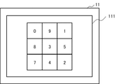
- the input terminal 11 causes the UI to display the received random number sequence pattern. In the present embodiment, the input terminal 11 is displayed on a UI including a random number column pattern arranged in a matrix of 3 rows ⁇ 3 columns.
- the authentication device 12 stores shared information shared between the user and the authentication device 12.
- the shared information includes passwords and sharing rules set for each user.
- the password is authentication information preset by the user. In this embodiment, an example of using a password consisting of three-digit numbers will be given.
- the sharing rule is a rule shared between the user and the authentication device 12.
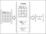
- the user calculates the key code according to the preset sharing rule using the numbers included in the random number sequence pattern displayed on the UI of the input terminal 11.
- the key code is a number string input as authentication information by the user in the random number sequence pattern displayed on the UI of the input terminal 11.
- the key code is valid only at one authentication opportunity, and the arrangement of numbers changes every time, so the leaked user authentication information will not be leaked.
- the authentication device 12 also calculates the key code according to the preset sharing rule using the random number sequence pattern. When the key code calculated by the user and the key code calculated by the authentication device 12 match, the authentication device 12 authenticates the user.
- Sharing rules include sharing patterns and calculation rules set for each user.
- the shared pattern is a pattern indicating the order in which a plurality of numbers included in the random number sequence pattern displayed on the UI of the input terminal 11 are selected.
- the calculation rule is a rule regarding a calculation that can be performed on each number selected from a plurality of numbers included in the random number sequence pattern based on the shared pattern.
- FIG. 2 is a conceptual diagram showing an example of a random number sequence pattern displayed on UI 111 of the input terminal 11.
- FIG. 2 shows a matrix of 9 different integers (0, 1, 2, 3, 4, 5, 7, 8, 9) selected from 10 integers from 0 to 9 in 3 rows ⁇ 3 columns.
- This is an example of a random number sequence pattern arranged in a shape.
- an example in which a one-digit number is arranged in each cell of the random number sequence pattern is shown, but the number of digits of the number displayed in each cell of the random number sequence pattern is not limited to one digit.
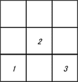
- FIG. 3 is a conceptual diagram showing an example of a shared pattern.
- the shared pattern indicates the order in which numbers are selected from the random number sequence pattern. Each number selected from the random number sequence pattern is called a temporary number.
- the formal numbers are expressed as the first formal number, the second formal number, ..., The m formal number according to the order in which they are selected (m is a natural number).
- the shared pattern of FIG. 3 in a random number column pattern arranged in a matrix of 3 rows ⁇ 3 columns, the first formal digit is selected from the third row and the first column, and the second formal digit is selected from the second row and the second column. Then, it is shown that the third temporary digit is selected from the third row and the third column.
- the first formal digit is "7"
- the second formal digit is "3”
- the third formal digit is "2".
- the password of a certain user is "721".
- the password is written as a first secret number, a second secret number, and a third secret number in order from the left of the three-digit number. That is, if the number of the password is n digits, it is expressed as a first secret number, a second secret number, ..., Nth secret number in order from the left of the number (n is a natural number).
- the key code if the number of the key code is n digits, it is described as the first key number, the second key number, ..., The nth key number in order from the left of the number.
- the calculation rule is to add the first formal number to the first secret number, add the second formal number to the second secret number, add the third formal number to the third secret number, and add the last digit of those numbers.
- the numbers will be arranged in order.
- the first key number of the key code is the first digit number "4" of "14" which is the sum of the first secret number "7" and the first temporary number "7". "become.
- the second key digit of the key code is the first digit "5" of "5" which is the sum of the second secret digit "2" and the second provisional digit "3". Become.
- the third key digit of the key code is the first digit "3" of "3" which is the sum of the third secret digit "1" and the third provisional digit "2". Become. That is, the key code is "453".
- the user and the authentication device 12 calculate the key code for each authentication opportunity by performing an operation using a predetermined password and a random number sequence pattern generated at the start of authentication based on the above sharing rule. ..
- the input terminal 11 transmits the key code input by the user to the authentication device 12.
- the authentication device 12 compares the key code calculated by the user with the key code calculated by the authentication device 12. When the key code calculated by the user and the key code calculated by the authentication device 12 match, the authentication device 12 authenticates the user. On the other hand, if the key code calculated by the user and the key code calculated by the authentication device 12 do not match, the authentication device 12 does not authenticate the user.
- the key code input to the UI of the input terminal 11 by the user in the above procedure is different each time, so it is an unpredictable number string. Further, since the number of the key code displayed on the UI of the input terminal 11 is displayed at an indefinite position every time, the display position cannot be predicted. That is, according to the method of the present embodiment, since the user's password and shared information cannot be specified, even if the user's key code input is stolen, the password and shared information will not be leaked. That is, according to the authentication method of the present embodiment, it is possible to construct an authentication system having a high security level.
- the input terminal 11 and the authentication device 12 constituting the authentication system 1 will be described with reference to the drawings.
- the input terminal 11 and the authentication device 12 will be described using functional blocks.
- the input terminal 11 and the authentication device 12 are realized by cooperative processing with a storage unit that stores the program, an information processing device including a processor that executes the program stored in the storage unit, and the like.
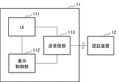
- FIG. 4 is a block diagram showing an example of the configuration of the input terminal 11.
- the input terminal 11 has a UI 111, a display control unit 112, and a transmission / reception unit 113.
- FIG. 4 also shows an authentication device 12 connected to the input terminal 11.
- UI111 is an interface that displays display information such as an operation screen and accepts operations on the operation screen.
- the UI 111 is realized by a touch panel or the like having both a display function and an input function.
- UI111 is used for inputting authentication information such as a password.
- the UI 111 is provided as a graphical user interface, a touch interface, or the like.
- the input terminal 11 is realized as an ATM, for example, the UI 111 is provided as a touch interface.
- UI 111 may be provided as a web user interface when authentication information is entered via the web.
- the display control unit 112 causes the UI 111 to display display information such as an operation screen.
- the display control unit 112 switches the display information to be displayed on the UI 111 according to a preset program.
- the display information to be displayed on the UI 111 and the program for switching the display information are stored in a storage unit (not shown).
- the transmission / reception unit 113 When the transmission / reception unit 113 detects the start of the authentication operation by the user, the transmission / reception unit 113 transmits the ID information of the user to the authentication device 12. For example, when the user's card is inserted into the input terminal 11, the transmission / reception unit 113 detects the start of the authentication operation by the user and transmits the ID information recorded on the card to the authentication device 12. For example, when the ID information is input via the UI 111, the transmission / reception unit 113 detects the start of the authentication operation by the user and transmits the input ID information to the authentication device 12. The transmission / reception unit 113 receives the random number sequence pattern transmitted from the authentication device from the authentication device 12 triggered by the reception of the ID information. Further, the transmission / reception unit 113 transmits the authentication information input via the UI 111 to the authentication device 12. The transmission / reception unit 113 receives the authentication result from the authentication device 12.
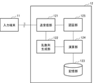
- FIG. 5 is a block diagram showing an example of the configuration of the authentication device 12.
- the authentication device 12 includes a transmission / reception unit 121, a random number sequence generation unit 122, a storage unit 123, a calculation unit 124, and an authentication unit 125.
- FIG. 5 also shows an input terminal 11 connected to the authentication device 12.
- the transmission / reception unit 121 receives a user ID from the input terminal 11.
- the transmission / reception unit 121 transmits the random number sequence pattern generated by the random number sequence generation unit 122 to the input terminal 11 in association with the user ID.
- the transmission / reception unit 121 receives the key code input by the user from the input terminal 11.
- the received key code for each user is authenticated by the authentication unit 125.
- the transmission / reception unit 121 transmits the authentication result of the authentication unit 125 to the input terminal 11.
- the transmission / reception unit 121 may send / receive data other than the user ID, the random number sequence pattern, the key code, and the authentication result to / from the input terminal 11.
- the random number sequence generation unit 122 generates a random number sequence pattern each time the transmission / reception unit 121 receives a user ID. For example, the random number column generation unit 122 randomly selects 9 different numbers from 10 integers from 0 to 9, and the selected 9 numbers are arranged in a matrix of 3 rows ⁇ 3 columns. Generate a column pattern. The number and arrangement of the numbers selected by the random number sequence generation unit 122 are not limited to the examples given here.
- the shared information for each user is stored in the storage unit 123.
- the shared information includes passwords and sharing rules set for each user.
- the password is authentication information preset by the user. For example, a password is a 3-digit or 4-digit number string.
- the sharing rule is a rule shared between the user and the authentication device 12. Sharing rules include sharing patterns and calculation rules set for each user.
- the shared pattern is a pattern indicating the order in which a plurality of numbers included in the random number sequence pattern displayed on the UI of the input terminal 11 are selected.
- the calculation rule is a rule regarding a calculation performed on each number sequentially selected based on a shared pattern from a plurality of numbers included in a random number sequence pattern.
- the calculation rule is to add the first formal number to the first secret number, add the second formal number to the second secret number, add the third formal number to the third secret number, and add the last digit of those numbers. It is to choose a number. Operation rules cannot be specified because different rules are set for each user.
- the calculation unit 124 selects a number from a plurality of numbers included in the random number sequence pattern based on the shared pattern associated with the user being authenticated, and performs a predetermined operation on each of the selected numbers. Execute to generate a key code.
- the key code is a number string input as authentication information by the user in the random number sequence pattern displayed on the UI of the input terminal 11.
- the calculation unit 124 adds one of the secret numbers included in the password to the temporary number selected based on the shared pattern, and selects the last digit of the calculation result. Is executed as a predetermined operation. For example, the calculation unit 124 subtracts one of the secret numbers included in the password from the temporary number selected based on the shared pattern, and selects the last digit of the absolute value of the calculation result. May be executed as a predetermined operation. For example, the calculation unit 124 multiplies one of the secret numbers included in the password by the formal number selected based on the shared pattern, and selects the last digit of the calculation result. Is executed as a predetermined operation.
- the arithmetic unit 124 divides any secret digit included in the password by a temporary digit selected based on the shared pattern, and divides the last digit of the calculated numerical value or any digit after the decimal point.
- the operation of selecting a numerical value such as, remainder, etc. is executed as a predetermined operation.
- the calculation executed by the calculation unit 124 is not limited to the method described here as long as it is shared between the user and the authentication device 12.
- the authentication unit 125 compares the key code calculated by the user being authenticated with the key code calculated by the calculation unit 124, and determines whether or not the user can be authenticated. When the key code calculated by the user and the key code calculated by the calculation unit 124 match, the authentication unit 125 generates an authentication result of authenticating the user. On the other hand, if the key code calculated by the user and the key code calculated by the calculation unit 124 do not match, the authentication unit 125 generates an authentication result that the user is not authenticated. The authentication result by the authentication unit 125 is transmitted to the input terminal 11 operated by the user during authentication.
- FIG. 6 is a shared information table (shared information table 131) showing an example of shared information stored in the storage unit 123 in the first example.
- the shared information table 131 stores shared information for each user ID (also referred to as identification information).
- FIG. 7 is a conceptual diagram for explaining the operation of the key code in the first example.
- the user ID “AAA” will be described with an example, and the user ID “BBB” and the user ID “CCC” will be omitted.
- the user ID "AAA” is associated with the password "721", the shared pattern of the user ID "AAA", and the calculation rule "A1".
- the shared pattern of the user ID "AAA” in the random number column pattern of 3 rows ⁇ 3 columns, the first temporary number is selected from the first row and the first column, and the second temporary number is selected from the second row and the second column. 3.
- the third temporary number is selected from the third row and the third column.
- the first secret number is added to the first secret number
- the second secret number is added to the second temporary number
- the third temporary number is added to the third secret number
- the last digit of those numbers is added. Defined as selecting the number of.
- the first pseudo digit is “7"
- the second pseudo digit is “3”
- the third pseudo digit is “2”.
- the first key number of the key code is "4", which is the first digit of "14”, which is the sum of "7”, which is the first secret number of the password, and "7", which is the first temporary number.
- the second key number of the key code is "5", which is the first digit of "5", which is the sum of "2”, which is the second secret number of the password, and "3", which is the second temporary number.
- the third key number of the key code is "3", which is the first digit of "3”, which is the sum of "1", which is the third secret number of the password, and "2", which is the third temporary number. "become. That is, the key code is "453".
- the random number sequence pattern may be regenerated in response to a request from the user.
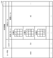
- FIG. 8 is a shared information table (shared information table 132) showing an example of shared information stored in the storage unit 123 in the second example. Shared information for each user ID is stored in the shared information table 132.
- FIG. 9 is a conceptual diagram for explaining the operation of the key code in the second example.
- the user ID "AAA” is associated with the password "721", the shared pattern of the user ID "AAA", and the calculation rule "A2".
- the shared pattern of the user ID "AAA” in the random number column pattern of 3 rows ⁇ 3 columns, the first temporary number is selected from the first row and the first column, and the second temporary number is selected from the second row and the second column. 3.
- the third temporary number is selected from the third row and the third column.
- the operation rule "A2" includes two operations. In the first operation included in the calculation rule "A2", the first secret number is added to the first secret number, the second secret number is added to the second temporary number, and the third temporary number is added to the third secret number. , It is an operation to select the last digit of those numbers.
- the second operation included in the operation rule "A2” is an operation of adding 1 to the number when the selected number is not included in the random number sequence pattern.
- the calculation rule may be a combination of a plurality of operations.
- the first pseudo digit is “8"
- the second pseudo digit is "5"
- the third pseudo digit is "0".
- the first key number of the key code is "5", which is the first digit of "15”, which is the sum of "7”, which is the first secret number of the password, and "8", which is the first temporary number.
- the second key number of the key code is "7”, which is the first digit of "7”, which is the sum of "2”, which is the second secret number of the password, and "5", which is the second temporary number.
- the third key digit of the key code is the first digit "1" which is the sum of "1” which is the third secret digit of the password and "0" which is the third provisional digit. Should be. However, since the random number sequence pattern does not include “1”, it is one of "1” which is the sum of "1” which is the third secret number of the password and "0” which is the third temporary number.
- the third key number is "2", which is the number obtained by adding 1 to the digit "1". That is, the key code is "572".
- the second example it is possible to deal with the case where the number included in the key code calculated by the method of the first example is not included in the random number sequence pattern. Further, according to the second example, since the calculation rule in which a plurality of operations are combined is used, the possibility that the user's authentication information is leaked is further reduced.
- FIG. 10 is a shared information table (shared information table 133) showing an example of shared information stored in the storage unit 123 in the third example. Shared information for each user ID is stored in the shared information table 133.
- FIG. 11 is a conceptual diagram for explaining the operation of the key code in the third example.
- the user ID "AAA” is associated with the password “721", the daily sharing pattern of the user ID "AAA", and the calculation rule "A2".
- the sharing pattern of the user ID "AAA” is set on a daily basis in association with the day of the week, such as Monday, Tuesday, Wednesday, and so on. In FIG. 10, the sharing pattern of Thursday, Friday, Saturday, and Sunday is omitted.
- the shared pattern of "Monday” in the random number column pattern of 3 rows ⁇ 3 columns, the first temporary number is selected from the first row and the first column, the second temporary number is selected from the first row and the first column, and 1 Indicates that the third temporary number is selected from the second row and the second column.
- the first temporary number is selected from the first row and the second column
- the second temporary number is selected from the first row and the third column
- 2 Indicates that the third temporary number is selected from the third row and the third column.
- the shared pattern of "Wednesday” in the random number column pattern of 3 rows x 3 columns, the 1st temporary number is selected from the 2nd row and 3rd column, and the 2nd temporary number is selected from the 3rd row and 3rd column. Indicates that the third temporary number is selected from the second row and the second column.
- the operation rule "A2" includes two operations.
- the first secret number is added to the first secret number
- the second secret number is added to the second temporary number
- the third temporary number is added to the third secret number.
- It is an operation to select the last digit of those numbers.
- the second operation included in the operation rule “A2" is an operation of adding 1 to the number when the selected number is not included in the random number sequence pattern.
- the first temporary digit is “8", the second temporary digit is “0”, and the third temporary digit is “9".
- the first key number of the key code is "5", which is the first digit of "15”, which is the sum of "7”, which is the first secret number of the password, and "8", which is the first temporary number.
- the second key number of the key code is "2”, which is the first digit of "2”, which is the sum of "2”, which is the second secret number of the password, and "0", which is the second temporary number.
- the third key number of the key code is "0", which is the first digit of "10”, which is the sum of "1”, which is the third secret number of the password, and "9", which is the third temporary number. ". That is, the key code for Monday is "520".
- the first temporary digit is “9"
- the second temporary digit is “1”
- the third temporary digit is "5".
- the first key number of the key code is "6”, which is the first digit of "16”, which is the sum of "7”, which is the first secret number of the password, and "9", which is the first temporary number. Should be. However, since the random number sequence pattern does not include “6”, it is one of "16” which is the sum of "7” which is the first secret number of the password and “9” which is the first temporary number.
- the first key number is "7”, which is the number obtained by adding 1 to the digit "6".
- the second key number of the key code is "3", which is the first digit of "3”, which is the sum of "2", which is the second secret number of the password, and "1", which is the second temporary number. "become.
- the third key number of the key code is "6", which is the first digit of "6”, which is the sum of "1”, which is the third secret number of the password, and "5", which is the third temporary number. Should be. However, since the random number sequence pattern does not include “6”, it is one of "6” which is the sum of "1” which is the third secret number of the password and "5" which is the third temporary number.
- the third key number is "7”, which is the number obtained by adding 1 to the digit "6". That is, the key code for Tuesday is "727".
- FIG. 12 is a shared information table (shared information table 134) showing an example of shared information stored in the storage unit 123 in the fourth example. Shared information for each user ID is stored in the shared information table 134.
- FIG. 13 is a conceptual diagram for explaining the operation of the key code in the fourth example.
- the user ID “AAA” will be described with an example, and the user ID “BBB” and the user ID “CCC” will be omitted.
- the user ID “AAA” is associated with the password “721", the shared pattern of the user ID “AAA”, and the calculation rule “A2".
- the shared pattern of the user ID “AAA” includes a first central digit "7", a second central digit "3", and a temporary digit selection order "clockwise”.
- the operation rule “A2" includes two operations. In the first operation included in the calculation rule “A2”, the first secret number is added to the first secret number, the second secret number is added to the second temporary number, and the third temporary number is added to the third secret number. , It is an operation to select the last digit of those numbers.
- the second operation included in the operation rule “A2” is an operation of adding 1 to the number when the selected number is not included in the random number sequence pattern.
- the first central digit "7" is the central digit when selecting a formal digit from the random number sequence pattern. For example, when “7" is included in the random number sequence pattern, temporary digits are sequentially selected in a clockwise order centered on "7".
- the second central digit "3" is a central digit when a pseudo number is selected from the random number sequence pattern when the first central digit "7" is not included in the random number sequence pattern. For example, when the random number sequence pattern does not include "7", the formal digits are selected in the clockwise order centered on "3". As the first to third temporary digits, consecutive numbers are selected in a clockwise order with the center number included in the random number sequence pattern as the center.
- the order of priority for selecting temporary digits is clockwise from the center digit to the top, diagonally upper right, right, diagonally lower right, lower, diagonally lower left, left, and diagonally upper left.
- the number above the center number is selected as the first number
- the number diagonally to the right of the center number is selected as the second number
- the number to the right of the center number is the third number. Is selected as.
- the number to the right of the center number is selected as the first number
- the number diagonally below the center number is selected as the second number, and the center.
- the number below the number is selected as the third provisional number.
- the digit below the central digit is selected as the first dummy digit, and the digit diagonally lower to the left of the central digit is selected as the second temporary digit.
- the number to the left of the number is selected as the third temporary number.
- the number to the left of the center number is selected as the first number, and the number diagonally above the center number is selected as the second number, and the center.
- the number above the number is selected as the third provisional number.
- the priority of selecting the temporary numbers is up, diagonally up left, left, diagonally down left, down, centering on the center number.
- the order is diagonally lower right, right, and diagonally upper right in the counterclockwise direction.
- FIG. 13 shows a pattern corresponding to each random number sequence pattern at the shared pattern.
- the symbols "AA”, “BB”, “CC”, and "DD" above the shared pattern indicate the corresponding random number sequence pattern.
- the random number sequence pattern "AA” includes the first central digit "7". Therefore, regarding the random number sequence pattern "AA”, based on the shared pattern, the "1" above the first central digit "7” is the first temporary digit, the second temporary digit is “2", and the first 3 The temporary number is "0".
- the first key number of the key code is "8”, which is the first digit of "8”, which is the sum of "7”, which is the first secret number of the password, and "1", which is the first temporary number.
- the second key number of the key code is "4", which is the first digit of "4", which is the sum of "2”, which is the second secret number of the password, and "2", which is the second temporary number. "become.
- the third key digit of the key code is the first digit "1" which is the sum of "1” which is the third secret digit of the password and "0" which is the third provisional digit. ". That is, the key code when the random number sequence pattern "AA" is used is "841".
- the random number sequence pattern "BB” includes the first central digit "7". Therefore, regarding the random number sequence pattern "BB”, based on the shared pattern, the "0" above the first central digit "7” is the first temporary digit, the second temporary digit is “6", and the first 3 The temporary number is "2".
- the first key number of the key code is "7”, which is the first digit of "7”, which is the sum of "7”, which is the first secret number of the password, and "0", which is the first temporary number. "become.
- the second key number of the key code is "8", which is the first digit of "8”, which is the sum of "2”, which is the second secret number of the password, and "6", which is the second temporary number. Is a password.
- the random number sequence pattern "BB” does not include “8"
- it is a numerical value obtained by adding "2" which is the second secret digit of the password and "6" which is the second temporary digit.
- the second key number is "9", which is the number obtained by adding 1 to the first digit number "8".
- the third key number of the key code is "3", which is the first digit of "3”, which is the sum of "1”, which is the third secret number of the password, and "2", which is the third temporary number. ". That is, the key code when the random number sequence pattern "BB” is used is "793".
- the random number sequence pattern "CC” includes the first central number "7", but since there are no numbers to the right and below the first central number "7", the numbers above the first central number "7" are used. Temporary numbers cannot be selected in clockwise order. Therefore, regarding the random number sequence pattern "CC”, based on the shared pattern, the "5" to the left of the first central digit "7” is the first temporary digit, the second temporary digit is “2", and the second one. 3 The temporary number is "3".
- the first key number of the key code is "2", which is the first digit of "12”, which is the sum of "7", which is the first secret number of the password, and "5", which is the first temporary number. "become.
- the second key number of the key code is "4", which is the first digit of "4", which is the sum of "2", which is the second secret number of the password, and "2", which is the second temporary number. "become.
- the third key number of the key code is "4", which is the first digit of "4", which is the sum of "1”, which is the third secret number of the password, and "3", which is the third temporary number. ". That is, the key code when the random number sequence pattern "CC" is used is "244".
- the random number sequence pattern "DD" does not include the first central digit "7", the second central digit "3" is the central digit. Therefore, regarding the random number sequence pattern "DD”, based on the shared pattern, the "4" to the right of the second central digit "3" is the first temporary digit, the second temporary digit is "8", and the second one. 3 The temporary number is "5".
- the first key number of the key code is "1”, which is the first digit of "11”, which is the sum of "7”, which is the first secret number of the password, and "4", which is the first temporary number. "become.
- the second key number of the key code is "0", which is the first digit of "10”, which is the sum of "2”, which is the second secret number of the password, and "8", which is the second temporary number. "become.
- the third key number of the key code is "6”, which is the first digit of "6”, which is the sum of "1”, which is the third secret number of the password, and "5", which is the third temporary number. ". That is, the key code when the random number sequence pattern “DD” is used is “106”.
- the rule for selecting temporary numbers according to the shared pattern is very complicated, so even if the key input is continuously stolen, the possibility that the password will be leaked is extremely low.
- FIG. 14 is a shared information table (shared information table 135) showing an example of shared information stored in the storage unit 123 in the fifth example.
- the shared information table 135 stores shared information for each user ID.
- FIG. 15 is a conceptual diagram for explaining the operation of the key code in the fifth example.
- the user ID “AAA” will be described with an example, and the user ID “BBB” and the user ID “CCC” will be omitted.
- the user ID "AAA” is associated with a password that is changed according to a predetermined rule every predetermined period, a shared pattern of the user ID "AAA", and a calculation rule "A2".
- the password for the user ID “AAA” is "3721" for the period from January to March, "7213” for the period from April to June, "2137” for the period from July to September, and "2137” for the period from October to December. 1372 ".
- the password is changed by moving the first digit of the password to the end at predetermined intervals.
- the rule for changing the password is not limited to the example given here as long as it is shared between the user and the authentication device 12.
- the password may be changed monthly or weekly.
- the password may be changed irregularly according to some rules instead of being changed at predetermined intervals.
- the first temporary digit is selected from the first row and the first column
- the second temporary digit is selected from the second row and the second column.
- 3rd row, 3rd column, 3rd temporary number is selected, and 1st row, 1st column, 4th temporary number is selected.
- the operation rule "A2" includes two operations. In the first operation included in the calculation rule “A2”, the first secret number is added to the first secret number, the second secret number is added to the second temporary number, and the third temporary number is added to the third secret number. , It is an operation to select the last digit of those numbers.
- the second operation included in the operation rule "A2" is an operation of adding 1 to the number when the selected number is not included in the random number sequence pattern.
- the fifth example an example of calculating a key code based on the shared information of the user ID “AAA” using a random number sequence pattern will be described.
- the following example shows an example of generating a key code for a password for each period of January to March, April to June, July to September, and October to December.
- the first formal digit is "8”
- the second formal digit is "5"
- the third formal digit is "0”. 4
- the temporary number is "4".
- the first key number of the key code is one of "11", which is the sum of the first secret number "3" of the password and the first temporary number "8". It should be the digit "1". However, since the random number sequence pattern does not include “1”, it is one of "11” which is the sum of "3” which is the first secret number of the password and "8" which is the first temporary number.
- the first key number is "2”, which is the number obtained by adding 1 to the digit "1”.
- the second key number of the key code is "2”, which is the first digit of "12”, which is the sum of "7”, which is the second secret number of the password, and "5", which is the second temporary number. "become.
- the third key number of the key code is "2", which is the first digit of "2”, which is the sum of "2", which is the third secret number of the password, and "0", which is the third temporary number.
- the 4th key number of the key code is "5", which is the first digit of "5" which is the sum of "1” which is the 4th secret number of the password and "4" which is the 4th temporary number. ". That is, the key code is "2225".
- the first key number of the key code is one of "15”, which is the sum of the first secret number "7” of the password and the first temporary number "8". It is the digit "5".
- the second key number of the key code is "7”, which is the first digit of "7”, which is the sum of "2”, which is the second secret number of the password, and "5", which is the second temporary number.
- the third key number of the key code is "2”, which is the first digit of "2”, which is the sum of "2”, which is the third secret number of the password, and "0", which is the third temporary number.
- the 4th key number of the key code is "7", which is the first digit of "7” which is the sum of "3" which is the 4th secret number of the password and "4" which is the 4th temporary number. ". That is, the key code is "5727".
- the key code for July-September is "0632”
- the key code for October-December is "9876”.
- an array of numbers included in the random number sequence pattern is newly generated for each authentication, so that the formal numbers based on the shared pattern are selected from different random number sequence patterns.
- the possibility that the password is leaked is extremely low even if the key input is continuously stolen for many months.
- shared information may be combined arbitrarily. For example, if the sharing pattern is changed on a daily basis and the password is changed according to a predetermined rule at a predetermined period, it becomes very difficult to guess the password from the key code entered by the user.
- FIG. 16 is an example of a window for accepting changes in the shared pattern, calculation rule, and password (shared information change window 150).
- the shared information change window 150 can be accessed from a link displayed on a web page or the like of a system that uses the authentication system 1.
- shared information including shared patterns, calculation rules, and passwords are displayed on the same screen at the same time, they are likely to be associated with each other. Therefore, it is preferable to configure them so that they are displayed on different screens. Therefore, it is preferable that the shared information change window 150 display only the link to the window for changing the shared pattern, the calculation rule, and the password. For example, if you click "Change shared pattern", you can change the shared pattern on the linked screen.
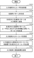
- FIG. 17 is a flowchart for explaining the operation of the input terminal 11.
- the input terminal 11 will be described as an operation main body.
- the input terminal 11 accepts a user ID by a user to be authenticated (step S111). For example, the input terminal 11 detects that the authentication card is inserted into the input terminal 11 or that the ID information is input on the authentication page on the web or the like as the start of the authentication operation.
- the input terminal 11 transmits the received user ID to the authentication device 12 (step S112).
- the input terminal 11 acquires the random number sequence pattern transmitted according to the user ID transmitted from the own device from the authentication device 12 (step S113).
- the input terminal 11 displays the acquired random number sequence pattern on the UI 111 of its own device (step S114).
- a key code consisting of numbers selected based on the sharing rule is input to the input terminal 11 by the authentication target user.
- the input terminal 11 transmits the key code input by the user to the authentication device 12 (step S115).
- the input terminal 11 receives the authentication result from the authentication device 12 (step S116).
- the input terminal 11 causes the UI 111 to display information according to the authentication result (step S117). For example, when authenticated by the authentication device 12, the authentication target user is provided with a service according to the authentication result.
- FIG. 18 is a flowchart for explaining the operation of the authentication device 12.
- the authentication device 12 will be described as an operation main body.
- the authentication device 12 receives the user ID of the user to be authenticated from the input terminal 11 (step S121).
- the authentication device 12 generates a random number sequence pattern in association with the user ID (step S122).
- the authentication device 12 transmits the generated random number sequence pattern to the input terminal 11 (step S123).
- the authentication device 12 generates a key code using the generated random number sequence pattern and the shared information corresponding to the user ID (step S124).
- the authentication device 12 receives the key code from the input terminal (step S125).
- the authentication device 12 compares the key code received from the input terminal 11 with the key code generated by the own device (step S126). When the key code received from the input terminal 11 and the key code generated by the own device match, the authentication device 12 generates an authentication result of authenticating the user being authenticated. If the key code received from the input terminal 11 and the key code generated by the own device do not match, the authentication device 12 generates an authentication result that the user being authenticated is not authenticated.
- the authentication device 12 transmits the authentication result to the input terminal 11 (step S127).
- a system that provides a service to an authenticated user provides a service to a user authenticated by the authentication device 12.
- the authentication system of this embodiment includes an input terminal and an authentication device.
- the input terminal and the authentication device are connected so as to be able to communicate with each other.
- the input terminal receives the identification information of the user to be authenticated and transmits the received identification information to the authentication device.
- the authentication device stores shared information including a password and a sharing rule preset for each user.
- the authentication device receives the identification information of the authentication target user from the input terminal operated by the authentication target user.
- the authentication device generates a random number sequence pattern composed of a plurality of different numbers according to the reception of the identification information of the user to be authenticated.
- the authentication device associates the generated random number sequence pattern with the identification information and sends it to the input terminal.
- the authentication device selects a plurality of formal digits from the random number sequence pattern based on the sharing rule.
- the authentication device generates a key code using a plurality of selected pseudo digits and a plurality of secret digits constituting the password.
- the input terminal receives the random number sequence pattern generated by the authentication device associated with the identification information from the authentication device.
- the input terminal displays the random number sequence pattern on the user interface of its own device.
- the input terminal transmits the key code selected from the random number sequence pattern to the authentication device via the user interface.
- the authentication device receives from the input terminal a key code consisting of numbers selected from the random number sequence pattern by the authentication target user based on the sharing rule.
- the authentication device authenticates the user to be authenticated based on the key code received from the input terminal and the key code generated by the own device.
- the authentication device has a transmission / reception unit, a random number sequence generation unit, a storage unit, a calculation unit, and an authentication unit.
- the random number sequence generator generates a random number sequence pattern composed of a plurality of different numbers for each authentication opportunity of the authentication target user.
- the arithmetic unit selects a plurality of formal digits from the random number sequence pattern based on the shared rule, and generates a key code using the plurality of selected formal digits and a plurality of secret digits constituting the password.
- the transmission / reception unit receives the identification information of the authentication target user from the input terminal operated by the authentication target user at the authentication opportunity of the authentication target user.
- the transmission / reception unit associates the random number sequence pattern generated at the authentication opportunity of the authentication target user with the identification information and transmits it to the input terminal.
- the transmission / reception unit receives from the input terminal a key code consisting of numbers selected from the random number sequence pattern by the authentication target user based on the sharing rule.
- the authentication unit authenticates the user to be authenticated based on the key code received from the input terminal and the key code generated by the calculation unit.
- the storage unit stores a sharing rule including a sharing pattern and a calculation rule preset by the user.
- the shared pattern is a pattern indicating the order in which formal numbers are selected from a random number sequence pattern in which a plurality of different numbers are arranged in a matrix.
- the calculation rule is a rule related to a calculation using a temporary digit selected from a random number sequence pattern and a secret digit constituting a password.
- a calculation rule includes a rule that a predetermined calculation is performed on a calculated numerical value.
- the storage unit stores a sharing pattern that is changed at predetermined intervals based on the rules shared with the user.
- the storage unit stores a shared pattern including a reference central digit and a pattern for selecting a temporary digit based on the central digit.
- the storage unit stores a password that is changed at predetermined intervals based on the rules shared with the user.
- a key code calculated using a random number string pattern temporarily generated by the authentication device based on the shared information shared between the user and the authentication device is obtained. Since it is used for authentication, leakage of authentication information can be prevented.
- the authentication device of this embodiment is used for authentication of ATMs installed in banks, post offices, convenience stores, train stations, and the like.
- the authentication device of the present embodiment is used for authentication in payments such as credit cards and online shopping.
- the authentication device of the present embodiment is used for authentication in opening and closing a door having a high security level.
- the authentication device of the present embodiment may be used in combination with biometric authentication such as fingerprint authentication, vein authentication, face authentication, iris authentication, and gait authentication.
- biometric authentication such as fingerprint authentication, vein authentication, face authentication, iris authentication, and gait authentication.
- the authentication device of the present embodiment is not limited to the example given here, and can be applied to arbitrary authentication using authentication information such as a password.
- the authentication system of the present embodiment is different from the first embodiment in that the operation of the key code by the user is performed on the authentication device side and the key code is transmitted to the mobile terminal used by the user.
- FIG. 19 is a block diagram showing an example of the configuration of the authentication system 2 of the present embodiment.
- the authentication system 2 includes an input terminal 21, an authentication device 22, and a mobile terminal 23.
- the input terminal 21 and the authentication device 22 are communicably connected via a network such as the Internet.
- the authentication device 22 and the mobile terminal 23 are communicably connected via a network such as the Internet.
- the input terminal 21 is provided as a dedicated terminal such as an ATM installed in a bank, a convenience store, or the like. Further, the input terminal 21 may be provided as application software (hereinafter, also referred to as an application) installed in a mobile terminal such as a personal computer or a smartphone. Since the input terminal 21 is the same as the input terminal 11 of the first embodiment, detailed description thereof will be omitted.
- the authentication device 22 is built on a server or a cloud.
- the authentication device 22 may be hardware or software.
- the mobile terminal 23 may be a general-purpose mobile device owned by the user, or may be a mobile device dedicated to authentication. When the mobile terminal 23 is realized by a general-purpose mobile device, it is not necessary to include the mobile terminal 23 in the configuration of the authentication system 2.
- the input terminal 21 When the input terminal 21 detects the start of the authentication operation by the user, the input terminal 21 transmits the ID information of the user to the authentication device 22.
- the authentication device 22 receives the user's ID information from the input terminal 21, the authentication device 22 generates a random number sequence pattern in association with the ID information.
- the authentication device 22 transmits the generated random number sequence pattern to the input terminal 21 that is the source of the ID information.
- the input terminal 21 displays the received random number sequence pattern on the user interface (UI: UserInterface) of its own device.
- UI UserInterface
- the authentication device 22 stores the shared information shared between the user and the authentication device 22.
- the shared information includes passwords and sharing rules set for each user.
- the password is authentication information preset by the user.
- the sharing rule is a rule shared between the user and the authentication device 22.
- the authentication device 22 calculates a key code according to a preset sharing rule using a random number sequence pattern generated at the time of user authentication.
- the authentication device 22 transmits the calculated key code to the mobile terminal 23.
- the mobile terminal 23 receives the key code from the authentication device 22.
- the mobile terminal 23 displays the key code received from the authentication device 22 on the screen of its own device.
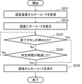
- the mobile terminal 23 erases the key code displayed on the screen in response to the user's operation. Further, the mobile terminal 23 erases the key code displayed on the screen after a predetermined time has elapsed. When the mobile terminal 23 erases the key code from the screen, the mobile terminal 23 deletes the key code from its own device.
- the mobile terminal 23 may display the numbers constituting the key code one by one in order.
- the mobile terminal 23 may display numbers constituting the key code according to the operation of the user.
- the mobile terminal 23 may display the numbers constituting the key code one by one by changing the display state such as font, size, color, thickness, inclination, and enclosure. In this way, if the numbers constituting the key code are not displayed all at once or are displayed in different display formats, the key code displayed on the screen of the mobile terminal 23 may be identified even if it is stolen. Is reduced.
- the user confirms the key code displayed on the mobile terminal 23 possessed by the user.
- the key code is a number string input as authentication information by the user in the random number sequence pattern displayed on the UI of the input terminal 21.
- the user inputs the key code displayed on the mobile terminal 23 into the random number sequence pattern displayed on the UI of the input terminal 21.
- the input terminal 21 transmits the key code input via the UI to the authentication device 22.
- the authentication device 22 receives the key code from the input terminal 21 operated by the user.
- the authentication device 22 compares the key code received from the input terminal 21 with the key code calculated by the authentication device 22. When the key code received from the input terminal 21 and the key code calculated by the authentication device 22 match, the authentication device 22 authenticates the user.
- FIG. 20 is a block diagram showing an example of the configuration of the authentication device 22.
- the authentication device 22 includes a transmission / reception unit 221, a random number sequence generation unit 222, a storage unit 223, an arithmetic unit 224, an authentication unit 225, and a key code transmission unit 226.
- FIG. 20 also shows an input terminal 21 and a mobile terminal 23 connected to the authentication device 22. Since the transmission / reception unit 221, the random number sequence generation unit 222, the storage unit 223, the calculation unit 224, and the authentication unit 225 are the same as the corresponding configurations included in the authentication device 12 of the first embodiment, detailed description thereof will be omitted. do.
- the key code transmission unit 226 transmits the key code calculated by the calculation unit 224 for the user being authenticated to the mobile terminal 23 possessed by the user.
- the transmission / reception unit 221 and the key code transmission unit 226 may be configured as a single unit.
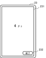
- FIG. 21 is a conceptual diagram showing an example in which a key code is displayed on the screen 231 of the mobile terminal 23.
- the mobile terminal 23 receives the key code used for authentication by the user who owns the own device from the authentication device, the mobile terminal 23 displays the key code on the screen 231 of the own device.
- the example of FIG. 21 shows a state in which the key code "453" is displayed on the screen 231 of the mobile terminal 23 in a different display state.
- FIG. 21 shows an example in which the end button 232 for turning off the display of the key code is displayed on the screen 231 on which the key code is displayed.
- the user who owns the mobile terminal 23 presses the end button 232 when he / she confirms the key code displayed on the screen 231 of the mobile terminal 23.
- the key code displayed on the screen 231 of the mobile terminal 23 disappears from the screen 231 when the end button 232 is pressed. In order to improve security, it is preferable that the key code displayed on the screen 231 of the mobile terminal 23 is deleted from the mobile terminal 23 at the timing when the end button 232 is pressed. If the key code disappears due to a malfunction by the user, the authentication using the input terminal 21 may be redone and the key code may be regenerated based on the new random number sequence pattern. Further, in order to improve security, it is preferable that the key code displayed on the screen 231 of the mobile terminal 23 is erased at the timing when a predetermined time has elapsed.
- FIG. 22 is a flowchart for explaining the operation of the input terminal 21.
- the input terminal 21 will be described as the operation main body.
- the processing of the input terminal 21 according to the flowchart of FIG. 22 is the same as the processing of the input terminal 11 according to the flowchart of FIG.
- the input terminal 21 accepts the user ID of the user to be authenticated (step S211). For example, the input terminal 21 detects that the authentication card is inserted into the input terminal 21 or that the ID information is input on the authentication page on the web or the like as the start of the authentication operation.
- the input terminal 21 transmits the received user ID to the authentication device 22 (step S212).
- the input terminal 21 acquires the random number sequence pattern transmitted according to the user ID transmitted from the own device from the authentication device 22 (step S213).
- the input terminal 21 displays the acquired random number sequence pattern on the UI of its own device (step S214).
- a key code consisting of numbers selected based on the sharing rule is input to the input terminal 21 by the authentication target user.
- the input terminal 21 transmits the key code input by the user to the authentication device 22 (step S215).
- the input terminal 21 receives the authentication result from the authentication device 22 (step S216).
- the input terminal 21 displays information according to the authentication result on the UI of its own device (step S217). For example, when authenticated by the authentication device 22, the authentication target user is provided with a service according to the authentication result.
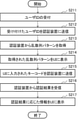
- FIG. 23 is a flowchart for explaining the operation of the authentication device 22.
- the authentication device 22 will be described as an operation main body.
- the authentication device 22 receives the user ID of the user to be authenticated from the input terminal 21 (step S221).
- the authentication device 22 generates a random number sequence pattern in association with the user ID (step S222).
- the authentication device 22 transmits the generated random number sequence pattern to the input terminal 21 (step S223).
- the authentication device 22 generates a key code using the generated random number sequence pattern and the shared information corresponding to the user ID (step S224).
- the authentication device 22 transmits the generated key code to the mobile terminal 23 (step S225).
- the authentication device 22 receives the key code from the input terminal 21 (step S226).
- the authentication device 22 compares the key code received from the input terminal 21 with the key code generated by the own device (step S227). When the key code received from the input terminal 21 and the key code generated by the own device match, the authentication device 22 generates an authentication result of authenticating the user being authenticated. If the key code received from the input terminal 21 and the key code generated by the own device do not match, the authentication device 22 generates an authentication result that the user being authenticated is not authenticated.
- the authentication device 22 transmits the authentication result to the input terminal 21 (step S228).
- a system that provides a service to an authenticated user provides a predetermined service to a user authenticated by the authentication device 22.
- FIG. 24 is a flowchart for explaining the operation of the mobile terminal 23.
- the mobile terminal 23 will be described as an operation main body.
- the mobile terminal 23 receives the key code used for authentication by the user who owns the own device from the authentication device 22 (step S231).
- the mobile terminal 23 displays the received key code on the screen of its own device (step S232).
- step S233 When the end button displayed on the screen of the own device is pressed (Yes in step S233), the mobile terminal 23 erases the key code from the screen (step S235).
- step S233 Even if the end button displayed on the screen of the own device is not pressed (No in step S233), even if the predetermined time has elapsed (Yes in step S234), the mobile terminal 23 erases the key code from the screen (step S235). ). If the predetermined time has not elapsed (No in step S234), the mobile terminal 23 waits for the end button to be pressed or the predetermined time to elapse.
- the authentication system of this embodiment includes an input terminal, an authentication device, and a mobile terminal.
- the input terminal and the authentication device are connected so as to be able to communicate with each other.
- the mobile terminal is possessed by the user to be authenticated and is communicably connected to the authentication device.
- the input terminal receives the identification information of the user to be authenticated and transmits the received identification information to the authentication device.
- the authentication device stores shared information including a password and a sharing rule preset for each user.
- the authentication device receives the identification information of the authentication target user from the input terminal operated by the authentication target user.
- the authentication device generates a random number sequence pattern composed of a plurality of different numbers according to the reception of the identification information of the user to be authenticated.
- the authentication device associates the generated random number sequence pattern with the identification information and sends it to the input terminal.
- the authentication device selects a plurality of formal digits from the random number sequence pattern based on the sharing rule.
- the authentication device generates a key code using a plurality of selected pseudo digits and a plurality of secret digits constituting the password.
- the authentication device transmits the generated key code to the mobile terminal used by the user to be authenticated.
- the input terminal receives the random number sequence pattern generated by the authentication device associated with the identification information from the authentication device.
- the input terminal displays the random number sequence pattern on the user interface of its own device.
- the mobile terminal displays the key code received from the authentication device on the screen of its own device.
- the input terminal transmits the key code input via the user interface to the authentication device by the user who has confirmed the key code of the mobile terminal.
- the authentication device receives from the input terminal a key code consisting of numbers selected from the random number sequence pattern by the authentication target user based on the sharing rule.
- the authentication device authenticates the user to be authenticated based on the key code received from the input terminal and the key code generated by the own device.
- the authentication is performed via the key code generated by the calculation method that cannot be specified from the outside, so that the leakage of the authentication information can be prevented. ..
- the authentication device of the present embodiment has a simplified configuration of the authentication device of the first to second embodiments.
- FIG. 25 is a block diagram showing an example of the configuration of the authentication device 32 of the present embodiment.
- the authentication device 32 includes a transmission / reception unit 321, a random number sequence generation unit 322, a storage unit 323, a calculation unit 324, and an authentication unit 325.
- the transmission / reception unit 321 receives the identification information of the authentication target user from the input terminal operated by the authentication target user at the authentication opportunity of the authentication target user.
- the transmission / reception unit 321 transmits the random number sequence pattern generated at the authentication opportunity of the authentication target user to the input terminal in association with the identification information.
- the transmission / reception unit 321 receives from the input terminal a key code consisting of numbers selected from the random number sequence pattern by the authentication target user based on the sharing rule.
- the random number sequence generation unit 322 generates a random number sequence pattern composed of a plurality of different numbers for each authentication opportunity of the authentication target user.
- the storage unit 323 stores shared information including a password and a sharing rule preset for each user.
- the calculation unit 324 selects a plurality of formal digits from the random number sequence pattern based on the sharing rule.
- the arithmetic unit 324 generates a key code using a plurality of selected temporary digits and a plurality of secret digits constituting the password.
- the authentication unit 325 authenticates the user to be authenticated based on the key code received from the input terminal and the key code generated by the calculation unit.
- a key code calculated using a random number string pattern temporarily generated by the authentication device based on the shared information shared between the user and the authentication device is obtained. Since it is used for authentication, leakage of authentication information can be prevented.
- the information processing apparatus 90 of FIG. 26 is a configuration example for executing the processing of the apparatus of each embodiment, and does not limit the scope of the present invention.
- the information processing device 90 includes a processor 91, a main storage device 92, an auxiliary storage device 93, an input / output interface 95, and a communication interface 96.
- the interface is abbreviated as I / F (Interface).
- the processor 91, the main storage device 92, the auxiliary storage device 93, the input / output interface 95, and the communication interface 96 are connected to each other via the bus 98 so as to be capable of data communication. Further, the processor 91, the main storage device 92, the auxiliary storage device 93, and the input / output interface 95 are connected to a network such as the Internet or an intranet via the communication interface 96.
- the processor 91 expands the program stored in the auxiliary storage device 93 or the like to the main storage device 92, and executes the expanded program.
- the software program installed in the information processing apparatus 90 may be used.
- the processor 91 executes processing by the apparatus according to each embodiment.
- the main storage device 92 has an area in which the program is expanded.
- the main storage device 92 may be a volatile memory such as a DRAM (Dynamic Random Access Memory). Further, a non-volatile memory such as MRAM (Magnetoresistive Random Access Memory) may be configured / added as the main storage device 92.
- DRAM Dynamic Random Access Memory
- MRAM Magnetic Random Access Memory
- the auxiliary storage device 93 stores various data.
- the auxiliary storage device 93 is composed of a local disk such as a hard disk or a flash memory. It is also possible to store various data in the main storage device 92 and omit the auxiliary storage device 93.
- the input / output interface 95 is an interface for connecting the information processing device 90 and peripheral devices.
- the communication interface 96 is an interface for connecting to an external system or device through a network such as the Internet or an intranet based on a standard or a specification.
- the input / output interface 95 and the communication interface 96 may be shared as an interface for connecting to an external device.
- the information processing device 90 may be configured to connect an input device such as a keyboard, a mouse, or a touch panel, if necessary. These input devices are used to input information and settings. When the touch panel is used as an input device, the display screen of the display device may also serve as the interface of the input device. Data communication between the processor 91 and the input device may be mediated by the input / output interface 95.
- the information processing apparatus 90 may be equipped with a display device for displaying information.
- a display device it is preferable that the information processing device 90 is provided with a display control device (not shown) for controlling the display of the display device.
- the display device may be connected to the information processing device 90 via the input / output interface 95.
- the above is an example of the hardware configuration for enabling the device according to each embodiment.
- the hardware configuration of FIG. 26 is an example of a hardware configuration for executing arithmetic processing of the apparatus according to each embodiment, and does not limit the scope of the present invention.
- the scope of the present invention also includes a program for causing a computer to execute processing related to the apparatus according to each embodiment.
- a recording medium on which a program according to each embodiment is recorded is also included in the scope of the present invention.
- the recording medium can be realized by, for example, an optical recording medium such as a CD (Compact Disc) or a DVD (Digital Versatile Disc).
- the recording medium may be realized by a semiconductor recording medium such as a USB (Universal Serial Bus) memory or an SD (Secure Digital) card, a magnetic recording medium such as a flexible disk, or another recording medium.
- the components of the device of each embodiment can be arbitrarily combined. Further, the components of the device of each embodiment may be realized by software or by a circuit.
Landscapes
- Engineering & Computer Science (AREA)
- Computer Security & Cryptography (AREA)
- Theoretical Computer Science (AREA)
- Signal Processing (AREA)
- Computer Networks & Wireless Communication (AREA)
- General Physics & Mathematics (AREA)
- Physics & Mathematics (AREA)
- Computer Hardware Design (AREA)
- Software Systems (AREA)
- General Engineering & Computer Science (AREA)
- Health & Medical Sciences (AREA)
- Bioethics (AREA)
- General Health & Medical Sciences (AREA)
- Storage Device Security (AREA)
Abstract
Description
まず、第1の実施形態に係る認証システムについて図面を参照しながら説明する。本実施形態の認証システムは、認証対象人物(認証対象ユーザとも呼ぶ)によって入力された認証情報に基づいて、その認証対象人物を認証する。例えば、本実施形態の認証システムは、ATM(Automatic Teller Machine)等の認証に用いられるパスワード(パスコードやパスフレーズなどとも呼ぶ)や暗証番号等の認証情報を用いた認証に適用される。以下においては、認証情報として、複数の数字によって構成されるパスワードを用いる例について説明する。本実施形態の手法は、数字を用いた認証であれば、任意の認証に用いることができる。
図1は、本実施形態に係る認証システム1の構成の一例を示すブロック図である。認証システム1は、入力端末11および認証装置12を備える。入力端末11と認証装置12は、インターネット等のネットワークを介して、通信可能に接続される。例えば、入力端末11は、ATMのような専用端末として提供される。また、入力端末11は、パーソナルコンピュータやスマートフォン等の携帯端末にインストールされたアプリケーションソフトウェア(以下、アプリとも呼ぶ)として提供されてもよい。認証装置12は、サーバやクラウドに構築される。認証装置12は、ハードウェアであってもよいし、ソフトウェアであってもよい。
図4は、入力端末11の構成の一例を示すブロック図である。入力端末11は、UI111、表示制御部112、および送受信部113を有する。図4には、入力端末11に接続される認証装置12も併せて図示する。
図5は、認証装置12の構成の一例を示すブロック図である。認証装置12は、送受信部121、乱数列生成部122、記憶部123、演算部124、および認証部125を有する。図5には、認証装置12に接続される入力端末11も併せて図示する。
次に、ユーザと認証装置12との間で共有される共有情報について、いくつかの例をあげて説明する。以下の例は、一例であって、ユーザと認証装置12との間で共有される共有情報について限定するものではない。
まず、共有情報の第1例について図面を参照しながら説明する。図6と図7は、ユーザと認証装置12との間で共有される共有情報の第1例に関する。図6は、第1例において、記憶部123に記憶される共有情報の一例を示す共有情報テーブル(共有情報テーブル131)である。共有情報テーブル131には、ユーザID(識別情報とも呼ぶ)ごとの共有情報が格納される。図7は、第1例におけるキーコードの演算について説明するための概念図である。以下においては、ユーザID「AAA」について一例をあげて説明し、ユーザID「BBB」とユーザID「CCC」については説明を省略する。
次に、共有情報の第2例について図面を参照しながら説明する。第1例では、0~9の10個の数字から異なる9個の数字を選択するため、算出された鍵数字が乱数列パターンに含まれない場合がある。第2例は、算出された鍵数字が乱数列パターンに含まれない場合に対応する例である。図8と図9は、ユーザと認証装置12との間で共有される共有情報の第2例に関する。図8は、第2例において、記憶部123に記憶される共有情報の一例を示す共有情報テーブル(共有情報テーブル132)である。共有情報テーブル132には、ユーザIDごとの共有情報が格納される。図9は、第2例におけるキーコードの演算について説明するための概念図である。
次に、共有情報の第3例について図面を参照しながら説明する。第3例は、共有パターンを日替わりで変更する例である。図10と図11は、ユーザと認証装置12との間で共有される共有情報の第3例に関する。図10は、第3例において、記憶部123に記憶される共有情報の一例を示す共有情報テーブル(共有情報テーブル133)である。共有情報テーブル133には、ユーザIDごとの共有情報が格納される。図11は、第3例におけるキーコードの演算について説明するための概念図である。
次に、共有情報の第4例について図面を参照しながら説明する。第4例は、乱数列パターンのマトリクスにおいて仮数字を選択する位置と順番ではなく、乱数列パターンに含まれるいずれかの数字を起点として仮数字を選択するパターンを共有パターンとして用いる例である。図12と図13は、ユーザと認証装置12との間で共有される共有情報の第4例に関する。図12は、第4例において、記憶部123に記憶される共有情報の一例を示す共有情報テーブル(共有情報テーブル134)である。共有情報テーブル134には、ユーザIDごとの共有情報が格納される。図13は、第4例におけるキーコードの演算について説明するための概念図である。以下においては、ユーザID「AAA」について一例をあげて説明し、ユーザID「BBB」とユーザID「CCC」については説明を省略する。
次に、共有情報の第5例について図面を参照しながら説明する。第5例は、所定の期間ごとにパスワードを変更する例である。図14と図15は、ユーザと認証装置12との間で共有される共有情報の第5例に関する。図14は、第5例において、記憶部123に記憶される共有情報の一例を示す共有情報テーブル(共有情報テーブル135)である。共有情報テーブル135には、ユーザIDごとの共有情報が格納される。図15は、第5例におけるキーコードの演算について説明するための概念図である。以下においては、ユーザID「AAA」について一例をあげて説明し、ユーザID「BBB」とユーザID「CCC」については説明を省略する。
次に、本実施形態の認証システム1の動作について図面を参照しながら説明する。以下においては、認証システム1を構成する入力端末11および認証装置12の各々を動作主体とする例について説明する。
図17は、入力端末11の動作について説明するためのフローチャートである。図17のフローチャートに沿った説明においては、入力端末11を動作主体として説明する。
図18は、認証装置12の動作について説明するためのフローチャートである。図18のフローチャートに沿った説明においては、認証装置12を動作主体として説明する。
次に、第2の実施形態に係る認証システムについて図面を参照しながら説明する。本実施形態の認証システムは、ユーザによるキーコードの演算を認証装置の側で行い、そのキーコードをユーザの使用する携帯端末に送信する点において、第1の実施形態とは異なる。
図19は、本実施形態の認証システム2の構成の一例を示すブロック図である。認証システム2は、入力端末21、認証装置22、および携帯端末23を備える。入力端末21と認証装置22は、インターネット等のネットワークを介して、通信可能に接続される。また、認証装置22と携帯端末23は、インターネット等のネットワークを介して、通信可能に接続される。
次に、本実施形態の認証システム2の動作について図面を参照しながら説明する。以下においては、認証システム2を構成する入力端末21、認証装置22、および携帯端末23を動作主体とする例について説明する。
図22は、入力端末21の動作について説明するためのフローチャートである。図22のフローチャートに沿った説明においては、入力端末21を動作主体として説明する。図22のフローチャートに沿った入力端末21の処理は、図17のフローチャートに沿った入力端末11の処理と同様である。
図23は、認証装置22の動作について説明するためのフローチャートである。図23のフローチャートに沿った説明においては、認証装置22を動作主体として説明する。
図24は、携帯端末23の動作について説明するためのフローチャートである。図24のフローチャートに沿った説明においては、携帯端末23を動作主体として説明する。
次に、第3の実施形態に係る認証装置について図面を参照しながら説明する。本実施形態の認証装置は、第1~第2の実施形態の認証装置を簡略化した構成である。
ここで、各実施形態に係る入力端末や認証端末、携帯端末等の装置による処理を実行するハードウェア構成について、図26の情報処理装置90を一例としてあげて説明する。なお、図26の情報処理装置90は、各実施形態の装置の処理を実行するための構成例であって、本発明の範囲を限定するものではない。
11、21 入力端末
12、22、32 認証装置
23 携帯端末
111 UI
112 表示制御部
113 送受信部
121、221、321 送受信部
122、222、322 乱数列生成部
123、223、323 記憶部
124、224、324 演算部
125、225、325 認証部
226 キーコード送信部
Claims (10)
- ユーザごとに予め設定されたパスワードおよび共有ルールを含む共有情報が記憶される記憶部と、
認証対象ユーザの認証機会ごとに、複数の異なる数字によって構成される乱数列パターンを生成する乱数列生成部と、
前記共有ルールに基づいて、前記乱数列パターンから複数の仮数字を選択し、選択された前記複数の仮数字と、前記パスワードを構成する複数の秘密数字とを用いてキーコードを生成する演算部と、
前記認証対象ユーザの認証機会において、前記認証対象ユーザの操作する入力端末から前記認証対象ユーザの識別情報を受信し、前記認証対象ユーザの認証機会に生成された前記乱数列パターンを前記識別情報に対応付けて前記入力端末に送信し、前記認証対象ユーザによって前記共有ルールに基づいて前記乱数列パターンから選択された数字からなる前記キーコードを前記入力端末から受信する送受信部と、
前記入力端末から受信された前記キーコードと、前記演算部によって生成された前記キーコードとに基づいて、前記認証対象ユーザを認証する認証部と、を備える認証装置。 - 前記記憶部は、
前記ユーザによって予め設定された共有パターンおよび演算ルールを含む前記共有ルールを記憶し、
前記共有パターンは、
複数の異なる数字がマトリックス状に配置された前記乱数列パターンから前記仮数字を選択する順番を示すパターンであり、
前記演算ルールは、
前記乱数列パターンから選択された前記仮数字と、前記パスワードを構成する前記秘密数字とを用いた演算に関するルールである請求項1に記載の認証装置。 - 前記記憶部は、
前記乱数列パターンから選択された前記仮数字と、前記パスワードを構成する前記秘密数字とを用いた演算によって算出された数値が、前記乱数列パターンを構成する前記複数の数字に含まれない場合、算出された前記数値に所定の演算を行うというルールを含む前記演算ルールを記憶する請求項2に記載の認証装置。 - 前記記憶部は、
前記ユーザと共有された規則に基づいて所定の期間ごとに変更される前記共有パターンを記憶する請求項2または3に記載の認証装置。 - 前記記憶部は、
基準となる中心数字と、前記中心数字を基準として前記仮数字を選択するパターンとを含む前記共有パターンを記憶する請求項2または3に記載の認証装置。 - 前記記憶部は、
前記ユーザと共有された規則に基づいて所定の期間ごとに変更される前記パスワードを記憶する請求項2または3に記載の認証装置。 - 前記認証対象ユーザの使用する携帯端末に、前記演算部によって生成された前記キーコードを送信するキーコード送信部を備える請求項1乃至6のいずれか一項に記載の認証装置。
- 請求項1乃至7のいずれか一項に記載の認証装置と、
前記認証装置に通信可能に接続される入力端末と、を備え、
前記入力端末は、
認証対象ユーザから受け付けた識別情報を前記認証装置に送信し、
前記識別情報に対応付けられて前記認証装置によって生成された乱数列パターンを前記認証装置から受信し、
前記乱数列パターンを自装置のユーザインタフェースに表示させ、
前記ユーザインタフェースを介して前記認証対象ユーザによって前記乱数列パターンから選択された数字からなるキーコードを前記認証装置に送信する認証システム。 - ユーザごとに予め設定されたパスワードおよび共有ルールを含む共有情報を記憶部に記憶しておき、
認証対象ユーザの操作する入力端末から前記認証対象ユーザの識別情報を受信し、
前記認証対象ユーザの識別情報の受信に応じて、複数の異なる数字によって構成される乱数列パターンを生成し、
生成された前記乱数列パターンを前記識別情報に対応付けて前記入力端末に送信し、
前記共有ルールに基づいて、前記乱数列パターンから複数の仮数字を選択し、
選択された前記複数の仮数字と、前記パスワードを構成する複数の秘密数字とを用いてキーコードを生成し、
前記認証対象ユーザによって前記共有ルールに基づいて前記乱数列パターンから選択された数字からなる前記キーコードを前記入力端末から受信し、
前記入力端末から受信された前記キーコードと、自装置で生成された前記キーコードとに基づいて、前記認証対象ユーザを認証する認証方法。 - ユーザごとに予め設定されたパスワードおよび共有ルールを含む共有情報を記憶部に記憶しておく処理と、
認証対象ユーザの操作する入力端末から前記認証対象ユーザの識別情報を受信する処理と、
前記認証対象ユーザの識別情報の受信に応じて、複数の異なる数字によって構成される乱数列パターンを生成する処理と、
生成された前記乱数列パターンを前記識別情報に対応付けて前記入力端末に送信する処理と、
前記共有ルールに基づいて、前記乱数列パターンから複数の仮数字を選択する処理と、
選択された前記複数の仮数字と、前記パスワードを構成する複数の秘密数字とを用いてキーコードを生成する処理と、
前記共有ルールに基づいて前記認証対象ユーザによって前記乱数列パターンから選択された数字からなる前記キーコードを前記入力端末から受信する処理と、
前記入力端末から受信された前記キーコードと、自装置で生成された前記キーコードとに基づいて、前記認証対象ユーザを認証する処理と、をコンピュータに実行させるプログラムが記録された非一過性の記録媒体。
Priority Applications (1)
| Application Number | Priority Date | Filing Date | Title |
|---|---|---|---|
| US18/025,151 US12542674B2 (en) | 2020-09-14 | 2021-08-19 | Authentication device, authentication method, and recording medium |
Applications Claiming Priority (2)
| Application Number | Priority Date | Filing Date | Title |
|---|---|---|---|
| JP2020153425A JP7002616B1 (ja) | 2020-09-14 | 2020-09-14 | 認証装置、認証方法、およびプログラム |
| JP2020-153425 | 2020-09-14 |
Publications (1)
| Publication Number | Publication Date |
|---|---|
| WO2022054519A1 true WO2022054519A1 (ja) | 2022-03-17 |
Family
ID=80560851
Family Applications (1)
| Application Number | Title | Priority Date | Filing Date |
|---|---|---|---|
| PCT/JP2021/030279 Ceased WO2022054519A1 (ja) | 2020-09-14 | 2021-08-19 | 認証装置、認証方法、および記録媒体 |
Country Status (3)
| Country | Link |
|---|---|
| US (1) | US12542674B2 (ja) |
| JP (1) | JP7002616B1 (ja) |
| WO (1) | WO2022054519A1 (ja) |
Families Citing this family (1)
| Publication number | Priority date | Publication date | Assignee | Title |
|---|---|---|---|---|
| US20240346130A1 (en) * | 2023-04-11 | 2024-10-17 | Capital One Services, Llc | Random password generation and update for digital service authentication |
Citations (3)
| Publication number | Priority date | Publication date | Assignee | Title |
|---|---|---|---|---|
| JP2005196800A (ja) * | 2002-02-13 | 2005-07-21 | Hideji Ogawa | ユーザ認証方法およびユーザ認証システム |
| JP2007264839A (ja) * | 2006-03-27 | 2007-10-11 | Cse:Kk | ユーザ認証システム、およびその方法 |
| JP2008276602A (ja) * | 2007-05-01 | 2008-11-13 | Chugoku Electric Power Co Inc:The | 認証方法及び認証装置 |
Family Cites Families (7)
| Publication number | Priority date | Publication date | Assignee | Title |
|---|---|---|---|---|
| US7036016B1 (en) * | 1998-02-12 | 2006-04-25 | Smith Jr A James | Method and apparatus for securing a list of passwords and personal identification numbers |
| JP4322355B2 (ja) | 1999-06-23 | 2009-08-26 | 眞 松本 | 電子認証装置 |
| EP2557507A3 (en) * | 2002-02-13 | 2013-10-23 | Passlogy Co., Ltd. | User verification method and user verification system |
| JP2006146327A (ja) | 2004-11-16 | 2006-06-08 | Toshiba Corp | 個人認証方法、装置及びプログラム |
| US8041954B2 (en) * | 2006-12-07 | 2011-10-18 | Paul Plesman | Method and system for providing a secure login solution using one-time passwords |
| JP5837987B2 (ja) * | 2011-09-30 | 2015-12-24 | インテル・コーポレーション | 自動化されたパスワード管理 |
| JP6721225B1 (ja) * | 2019-11-28 | 2020-07-08 | 株式会社シー・エス・イー | ユーザ認証システム、ユーザ認証サーバ、およびユーザ認証方法 |
-
2020
- 2020-09-14 JP JP2020153425A patent/JP7002616B1/ja active Active
-
2021
- 2021-08-19 WO PCT/JP2021/030279 patent/WO2022054519A1/ja not_active Ceased
- 2021-08-19 US US18/025,151 patent/US12542674B2/en active Active
Patent Citations (3)
| Publication number | Priority date | Publication date | Assignee | Title |
|---|---|---|---|---|
| JP2005196800A (ja) * | 2002-02-13 | 2005-07-21 | Hideji Ogawa | ユーザ認証方法およびユーザ認証システム |
| JP2007264839A (ja) * | 2006-03-27 | 2007-10-11 | Cse:Kk | ユーザ認証システム、およびその方法 |
| JP2008276602A (ja) * | 2007-05-01 | 2008-11-13 | Chugoku Electric Power Co Inc:The | 認証方法及び認証装置 |
Also Published As
| Publication number | Publication date |
|---|---|
| JP2022047574A (ja) | 2022-03-25 |
| US12542674B2 (en) | 2026-02-03 |
| JP7002616B1 (ja) | 2022-01-20 |
| US20240333491A1 (en) | 2024-10-03 |
Similar Documents
| Publication | Publication Date | Title |
|---|---|---|
| US20190260747A1 (en) | Securing a transaction performed from a non-secure terminal | |
| ES2276279T3 (es) | Teclado virtual. | |
| ES2908346T3 (es) | Métodos y sistemas de autenticación | |
| JP4925121B2 (ja) | フェイクポインタによる暗証番号入力装置および暗証番号入力方法 | |
| US20160127134A1 (en) | User authentication system and method | |
| CN103034798B (zh) | 一种随机密码的生成方法及装置 | |
| WO2015100475A1 (en) | Secure storage of data among multiple devices | |
| KR101473640B1 (ko) | 터치 단말기 및 터치 단말기의 패스워드 생성 방법 | |
| JP2008537210A (ja) | 安全保証されたデータ通信方法 | |
| US8117652B1 (en) | Password input using mouse clicking | |
| JP2015007941A (ja) | パスワードの入力方法、入力端末、及び入力システム | |
| JP7002616B1 (ja) | 認証装置、認証方法、およびプログラム | |
| JP4799476B2 (ja) | 認証方法及び認証装置 | |
| WO2011124267A1 (en) | Authentication system and method thereof | |
| KR20180048423A (ko) | 비-보안 단말에서 수행되는 트랜잭션을 안전하게 보호하는 방법 | |
| CN109891821A (zh) | 用于使用非安全终端安全地执行敏感性操作的方法 | |
| KR101063523B1 (ko) | 2개 이상의 문자로 구성되는 사용자 인증 패스워드를 이용한 사용자 인증 방법 | |
| KR20180048425A (ko) | 단말의 사용자에게 비밀 데이터를 안전하게 전송하는 방법 | |
| KR20180048424A (ko) | 비-보호 단말에 의해 사용자를 인증하는 방법 | |
| US11449597B2 (en) | Transposed passwords | |
| RU2690221C1 (ru) | Система аутентификации пользователей в промышленных условиях | |
| KR101459912B1 (ko) | 3차원 디스플레이를 위한 사용자 인증 방법 및 장치 | |
| US20240386090A1 (en) | Mutual authentication system and method | |
| JP2011164716A (ja) | 認証装置、認証方法及びコンピュータプログラム | |
| KR20180048426A (ko) | 단말의 사용자에게 비밀 데이터를 안전하게 전송하는 방법 |
Legal Events
| Date | Code | Title | Description |
|---|---|---|---|
| 121 | Ep: the epo has been informed by wipo that ep was designated in this application |
Ref document number: 21866479 Country of ref document: EP Kind code of ref document: A1 |
|
| WWE | Wipo information: entry into national phase |
Ref document number: 18025151 Country of ref document: US |
|
| NENP | Non-entry into the national phase |
Ref country code: DE |
|
| 122 | Ep: pct application non-entry in european phase |
Ref document number: 21866479 Country of ref document: EP Kind code of ref document: A1 |
|
| WWG | Wipo information: grant in national office |
Ref document number: 18025151 Country of ref document: US |