WO2022054227A1 - Heat cooker and heat cooker system - Google Patents
Heat cooker and heat cooker system Download PDFInfo
- Publication number
- WO2022054227A1 WO2022054227A1 PCT/JP2020/034477 JP2020034477W WO2022054227A1 WO 2022054227 A1 WO2022054227 A1 WO 2022054227A1 JP 2020034477 W JP2020034477 W JP 2020034477W WO 2022054227 A1 WO2022054227 A1 WO 2022054227A1
- Authority
- WO
- WIPO (PCT)
- Prior art keywords
- heating
- heating coil
- power
- drive circuit
- coil
- Prior art date
Links
- 238000010438 heat treatment Methods 0.000 claims abstract description 361
- 230000006698 induction Effects 0.000 claims abstract description 68
- 238000011084 recovery Methods 0.000 claims abstract description 56
- 230000004907 flux Effects 0.000 claims abstract description 31
- 238000010411 cooking Methods 0.000 claims description 61
- 239000000758 substrate Substances 0.000 claims description 8
- RYGMFSIKBFXOCR-UHFFFAOYSA-N Copper Chemical compound [Cu] RYGMFSIKBFXOCR-UHFFFAOYSA-N 0.000 claims description 5
- 239000011889 copper foil Substances 0.000 claims description 5
- 230000002093 peripheral effect Effects 0.000 claims description 4
- 210000000352 storage cell Anatomy 0.000 abstract 2
- 239000003990 capacitor Substances 0.000 description 33
- 238000010586 diagram Methods 0.000 description 18
- 230000001965 increasing effect Effects 0.000 description 9
- 230000001939 inductive effect Effects 0.000 description 4
- 229910000859 α-Fe Inorganic materials 0.000 description 4
- 239000004065 semiconductor Substances 0.000 description 3
- 238000004804 winding Methods 0.000 description 3
- 230000006870 function Effects 0.000 description 2
- 238000009499 grossing Methods 0.000 description 2
- 238000004519 manufacturing process Methods 0.000 description 2
- 238000007639 printing Methods 0.000 description 2
- WHXSMMKQMYFTQS-UHFFFAOYSA-N Lithium Chemical compound [Li] WHXSMMKQMYFTQS-UHFFFAOYSA-N 0.000 description 1
- 238000013459 approach Methods 0.000 description 1
- 239000000470 constituent Substances 0.000 description 1
- 230000005674 electromagnetic induction Effects 0.000 description 1
- 238000005516 engineering process Methods 0.000 description 1
- 229910052744 lithium Inorganic materials 0.000 description 1
- 239000000696 magnetic material Substances 0.000 description 1
- 238000000034 method Methods 0.000 description 1
Images


Classifications
-
- H—ELECTRICITY
- H05—ELECTRIC TECHNIQUES NOT OTHERWISE PROVIDED FOR
- H05B—ELECTRIC HEATING; ELECTRIC LIGHT SOURCES NOT OTHERWISE PROVIDED FOR; CIRCUIT ARRANGEMENTS FOR ELECTRIC LIGHT SOURCES, IN GENERAL
- H05B6/00—Heating by electric, magnetic or electromagnetic fields
- H05B6/02—Induction heating
- H05B6/10—Induction heating apparatus, other than furnaces, for specific applications
- H05B6/12—Cooking devices
- H05B6/1209—Cooking devices induction cooking plates or the like and devices to be used in combination with them
- H05B6/1245—Cooking devices induction cooking plates or the like and devices to be used in combination with them with special coil arrangements
-
- H—ELECTRICITY
- H05—ELECTRIC TECHNIQUES NOT OTHERWISE PROVIDED FOR
- H05B—ELECTRIC HEATING; ELECTRIC LIGHT SOURCES NOT OTHERWISE PROVIDED FOR; CIRCUIT ARRANGEMENTS FOR ELECTRIC LIGHT SOURCES, IN GENERAL
- H05B6/00—Heating by electric, magnetic or electromagnetic fields
- H05B6/02—Induction heating
- H05B6/10—Induction heating apparatus, other than furnaces, for specific applications
- H05B6/12—Cooking devices
- H05B6/1209—Cooking devices induction cooking plates or the like and devices to be used in combination with them
- H05B6/1236—Cooking devices induction cooking plates or the like and devices to be used in combination with them adapted to induce current in a coil to supply power to a device and electrical heating devices powered in this way
-
- H—ELECTRICITY
- H05—ELECTRIC TECHNIQUES NOT OTHERWISE PROVIDED FOR
- H05B—ELECTRIC HEATING; ELECTRIC LIGHT SOURCES NOT OTHERWISE PROVIDED FOR; CIRCUIT ARRANGEMENTS FOR ELECTRIC LIGHT SOURCES, IN GENERAL
- H05B6/00—Heating by electric, magnetic or electromagnetic fields
- H05B6/02—Induction heating
- H05B6/06—Control, e.g. of temperature, of power
- H05B6/062—Control, e.g. of temperature, of power for cooking plates or the like
-
- H—ELECTRICITY
- H05—ELECTRIC TECHNIQUES NOT OTHERWISE PROVIDED FOR
- H05B—ELECTRIC HEATING; ELECTRIC LIGHT SOURCES NOT OTHERWISE PROVIDED FOR; CIRCUIT ARRANGEMENTS FOR ELECTRIC LIGHT SOURCES, IN GENERAL
- H05B6/00—Heating by electric, magnetic or electromagnetic fields
- H05B6/02—Induction heating
- H05B6/10—Induction heating apparatus, other than furnaces, for specific applications
- H05B6/12—Cooking devices
- H05B6/1209—Cooking devices induction cooking plates or the like and devices to be used in combination with them
- H05B6/1245—Cooking devices induction cooking plates or the like and devices to be used in combination with them with special coil arrangements
- H05B6/1272—Cooking devices induction cooking plates or the like and devices to be used in combination with them with special coil arrangements with more than one coil or coil segment per heating zone
-
- Y—GENERAL TAGGING OF NEW TECHNOLOGICAL DEVELOPMENTS; GENERAL TAGGING OF CROSS-SECTIONAL TECHNOLOGIES SPANNING OVER SEVERAL SECTIONS OF THE IPC; TECHNICAL SUBJECTS COVERED BY FORMER USPC CROSS-REFERENCE ART COLLECTIONS [XRACs] AND DIGESTS
- Y02—TECHNOLOGIES OR APPLICATIONS FOR MITIGATION OR ADAPTATION AGAINST CLIMATE CHANGE
- Y02B—CLIMATE CHANGE MITIGATION TECHNOLOGIES RELATED TO BUILDINGS, e.g. HOUSING, HOUSE APPLIANCES OR RELATED END-USER APPLICATIONS
- Y02B40/00—Technologies aiming at improving the efficiency of home appliances, e.g. induction cooking or efficient technologies for refrigerators, freezers or dish washers
Definitions
- the present disclosure relates to a cooker and a cooker system that induces and heats an object to be heated.
- the electric power obtained from the current flowing through the leakage flux recovery coil is used as the driving electric power of the drive circuit that supplies the high frequency current to the heating coil. Since the use of electric power that has not been used as such leakage magnetic flux is effective for energy saving, a cooking cooker that can further utilize the electric power generated by receiving the leakage magnetic flux has been desired.
- the present disclosure is a technology against the background of the above-mentioned problems, and provides a cooking cooker and a cooking cooker system that can utilize the electric power generated by receiving the leakage magnetic flux from the heating coil.
- the heating cooker includes a top plate provided with a heating port in which an object to be heated is placed, a heating coil provided under the heating port, and a leakage current from the heating coil.
- a power recovery coil that receives power to generate power
- a storage battery that stores the power generated by the power recovery coil
- a first drive circuit that receives power from a commercial power source and supplies a high-frequency current to the heating coil, and the above.
- the second drive circuit that receives power from the storage battery and supplies a high-frequency current to the heating coil, and the heating coil to which the high-frequency current is supplied from the first drive circuit to the object to be heated placed on the heating port.
- the power receiving device mounted on the heating port is provided with a control device having an induced heating mode for inductive heating and a power feeding mode in which a high-frequency current is supplied from the second drive circuit by the heating coil. It is a thing.
- the heating cooker system according to the present disclosure accommodates a top plate provided with a heating port, which is an area on which an object to be heated is placed, a heating coil provided under the heating port, and the heating coil.
- a heating cooker provided with a housing and a power recovery coil that receives a leakage magnetic flux from the heating coil to generate power, and power generated by the power recovery coil arranged outside the housing.
- a heating cooker system including a storage battery for storing, wherein the heating cooker receives power from a commercial power source and supplies high-frequency current to the heating coil, and power is supplied from the storage battery.
- a second drive circuit that receives and supplies a high-frequency current to the heating coil and an object to be heated placed on the heating port are induced and heated by the heating coil to which a high-frequency current is supplied from the first drive circuit. It is provided with a control device having a heating mode and a power feeding mode in which a power receiving device mounted on the heating port is supplied with a power supply by the heating coil to which a high frequency current is supplied from the second drive circuit.
- the electric power generated by receiving the leakage magnetic flux from the heating coil can be used to supply power to the power receiving device mounted on the heating port.
- FIG. It is external perspective view of the cooking apparatus which concerns on Embodiment 1.
- FIG. It is a functional block diagram of the cooking apparatus which concerns on Embodiment 1.
- FIG. It is a functional block diagram of the cooking apparatus which concerns on Embodiment 1.
- FIG. It is a figure explaining the circuit configuration example of the cooking apparatus which concerns on Embodiment 1.
- FIG. It is a figure explaining the relationship between the frequency of the high frequency current supplied to the cooking apparatus 100 which concerns on Embodiment 1, and the output power.
- It is a control flowchart of the cooking apparatus which concerns on Embodiment 1.
- FIG. It is a functional block diagram of the cooking apparatus which concerns on Embodiment 2.
- FIG. It is a functional block diagram of the cooking apparatus which concerns on Embodiment 2.
- FIG. It is a functional block diagram of the cooking apparatus which concerns on Embodiment 2.
- FIG. It is a figure explaining the circuit configuration example of the cooking apparatus which concerns on Embodiment 2.
- FIG. It is a control flowchart of the cooking apparatus which concerns on Embodiment 3.
- FIG. It is a figure explaining the relationship between the frequency of the high frequency current supplied to the cooking apparatus 100 which concerns on Embodiment 3, and output power.
- FIG. It is a functional block diagram of the cooking apparatus system which concerns on Embodiment 5.
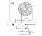
- FIG. 1 is an external perspective view of the cooking device 100 according to the first embodiment.
- the heating cooker 100 has a top plate 1 on which an object to be heated such as a pot is placed, and a housing 2 provided under the top plate 1.
- the housing 2 is provided with an operation unit 3 having a button, a switch, or the like for receiving an operation input of a user.
- the cooking cooker 100 is provided with a display unit 4 for displaying the operating state of the cooking cooker 100 and the contents of the operation input of the user.
- the operation unit 3 of the present embodiment includes a first operation unit 3a for instructing execution of either the induction heating mode or the power supply mode, which will be described later.
- the first operation unit 3a may include an input device for instructing the execution of the induction heating mode and an input device for instructing the execution of the power supply mode, respectively, and either the induction heating mode or the power supply mode can be selected. It may be provided with a switching device for selecting uniformly.
- the specific configurations of the operation unit 3 and the display unit 4 are not limited to those shown in the drawings.
- the top plate 1 has three heating ports 5.
- the heating port 5 is an area on which a heated object such as a pot is placed.
- a heating port 5 is printed on the top plate 1.
- the heating coil 6 provided in one heating port 5 is shown by a broken line.
- the heating coils 6 described below can be provided in all or part of the three heating ports 5.
- FIG. 2 is a functional block diagram of the cooking device 100 according to the first embodiment.
- FIG. 2 also shows the planar positional relationship between the heating coil 6 and the power recovery coil 7.
- FIG. 3 is a functional block diagram of the cooking device 100 according to the first embodiment.
- FIG. 3 also shows the vertical positional relationship between the heating coil 6 and the power recovery coil 7 and the object to be heated 51.
- FIGS. 2 and 3 also show a commercial power supply 50. 2 and 3 show only the configuration corresponding to one of the three heating ports 5 of the cooking cooker 100 shown in FIG. 1.
- the cooking cooker 100 includes a heating coil 6, a power recovery coil 7, a control device 10, a first drive circuit 11, a second drive circuit 12, and a storage battery 14.
- the heating cooker 100 of the present embodiment further includes an inductance changing unit 13 that changes the inductance value of the heating coil 6.
- the heating coil 6 is formed by winding a conducting wire in an annular shape. In this embodiment, one heating coil 6 is provided for one heating port 5. The heating coil 6 is used for induction heating of the object to be heated 51 placed on the heating port 5 and for supplying power to the power receiving device mounted on the heating port 5.
- the power recovery coil 7 is formed by winding a conducting wire in an annular shape.
- the shape of the power recovery coil 7 is not limited to the annular shape.
- the power recovery coil 7 is arranged at a position where it intersects with the magnetic flux generated from the heating coil 6.
- the power recovery coil 7 of the present embodiment is positioned so as to overlap the heating coil 6 in a plane as shown in FIG. 2, and is arranged below the heating coil 6 as shown in FIG.
- a storage battery 14 is connected to the power recovery coil 7 via a rectifier circuit 15.
- the rectifier circuit 15 converts the AC voltage generated by the power recovery coil 7 into a DC voltage and smoothes it.
- the rectifier circuit 15 has, for example, a rectifier diode and a smoothing capacitor. It is desirable that the DC voltage completely smoothed by the rectifier circuit 15 is input to the storage battery 14, but the DC voltage superimposed on the ripple may be applied to the storage battery 14.
- the storage battery 14 stores electric power smoothed by the rectifier circuit 15.
- the storage battery 14 is a secondary battery such as a lithium battery.
- the control device 10 controls the first drive circuit 11, the second drive circuit 12, the inductance changing unit 13, and the display unit 4 based on the operation signal input from the operation unit 3.
- the control device 10 is composed of dedicated hardware or a CPU (Central Processing Unit) that executes a program stored in a memory.
- a CPU Central Processing Unit
- each function executed by the control device 10 is realized by software, firmware, or a combination of software and firmware.
- Software and firmware are written as programs and stored in memory.
- the CPU realizes each function of the control device 10 by reading and executing a program stored in the memory.
- the memory is a non-volatile or volatile semiconductor memory such as RAM, ROM, flash memory, EPROM, EEPROM and the like.
- the first drive circuit 11 is an inverter circuit that converts an alternating current input from the commercial power supply 50 into a high frequency current and outputs it.
- the high frequency current output from the first drive circuit 11 is supplied to the heating coil 6.
- the second drive circuit 12 is an inverter circuit that converts the direct current input from the storage battery 14 into a high frequency current and outputs it.
- the high frequency current output from the second drive circuit 12 is supplied to the heating coil 6.
- the inductance changing unit 13 switches the inductance value of the heating coil 6 between the first value and the second value, which is a value smaller than the first value.
- a specific configuration example of the inductance changing unit 13 will be described later.
- the control device 10 of the heating cooker 100 of the present embodiment has two control modes, an induction heating mode and a power feeding mode.
- the induction heating mode is a control mode for inducing heating an object to be heated 51 such as a pot placed on the heating port 5.
- the power supply mode is a control mode for non-contact power supply to the power receiving device mounted on the heating port 5.
- a heated object 51 such as a pot is placed on the heating port 5.
- a high-frequency current is supplied to the heating coil 6, a magnetic flux is generated from the heating coil 6, and an eddy current is generated in the object to be heated 51 placed on the heating port 5 and interlinking with the magnetic flux.
- the Joule heat generated by this eddy current raises the temperature of the object to be heated 51. In this way, the object to be heated 51 placed on the heating port 5 is induced and heated.
- electric power from the commercial power source 50 is supplied to the heating coil 6 via the first drive circuit 11.
- an electromotive force is generated in the power recovery coil 7 in a direction that cancels the change in the magnetic flux, and a current flows through the power recovery coil 7.
- the electromotive force generated in the power recovery coil 7 is rectified by the rectifier circuit 15 to charge the storage battery 14.
- the storage battery 14 is charged at the same time as the induction heating of the object to be heated 51.
- a power receiving device When the power supply mode is executed, a power receiving device is placed on the heating port 5.
- the power receiving device is a device provided with a power receiving coil and using the current flowing through the power receiving coil as electric power.
- a high-frequency current is supplied to the heating coil 6 in the power feeding mode, a magnetic flux is generated from the heating coil 6, and the generated magnetic flux generates an electromotive force due to electromagnetic induction in the power receiving coil of the power receiving device.
- the high frequency current flowing through the power receiving coil of the power receiving device is used in the power receiving device.
- the electric power from the storage battery 14 is supplied to the heating coil 6 via the second drive circuit 12.
- the heating coil 6 provided in the heating port 5 is used in both the induction heating mode and the power feeding mode, and the heating port 5 is a place where the object to be heated to be induced is placed and also a place where the power receiving device is placed. be. Therefore, the user does not get lost in the place where the heated object and the power receiving device are placed, which is highly convenient.
- the heating cooker 100 of the present embodiment has an induction heating mode and a power feeding mode. Then, the storage battery 14 is charged in the induction heating mode, and the storage battery 14 is used to supply power to the power receiving device in the power supply mode. Therefore, according to the present embodiment, the leakage magnetic flux generated in the induction heating mode can be effectively utilized for supplying power to the power receiving device. Since power can be transmitted to the power receiving device without using the output of the commercial power source 50, energy saving can be promoted. Further, since the storage battery 14 is charged when cooking is performed in the induction heating mode of the heating cooker 100, the user does not have to perform an operation for charging the storage battery 14, and the user does not have to perform the operation for charging the storage battery 14. You can save the trouble of. Further, since the cooking device 100 of the present embodiment is provided with the storage battery 14, even if the commercial power source 50 is lost due to a power failure disaster, for example, power can be transmitted to the power receiving device, which is convenient for the user. Can be improved.
- the power that can be received can be about 10 W. Therefore, even if the output voltage of the storage battery 14 is smaller than that of the commercial power source 50 due to the upper limit of the charge capacity of the storage battery 14, the power obtained from the leakage magnetic flux can be sufficiently utilized for supplying power to the power receiving device. ..
- the heating coil 6 that induces and heats the object to be heated 51 placed on the heating port 5 on a one-to-one basis as in the present embodiment can perform induction heating at a high output in order to improve convenience in cooking.
- Inductance value is required.
- the output required for induction cooking is about 100 W to 3000 W.
- the present embodiment includes an inductance changing unit 13 that changes the inductance value of the heating coil 6.
- FIG. 4 is a diagram illustrating a circuit configuration example of the cooking cooker 100 according to the first embodiment.
- the first drive circuit 11 illustrated in FIG. 4 is a half-bridge type inverter having a switching element 111 and a switching element 112.
- the switching element 111 and the switching element 112 are connected in series between the power supply line connected to the commercial power supply 50 and the GND line.
- the output point of the first drive circuit 11 is connected to the heating coil 6.
- the second drive circuit 12 illustrated in FIG. 4 is a half-bridge type inverter having a switching element 121 and a switching element 122.
- the switching element 121 and the switching element 122 are connected in series between the power supply line connected to the storage battery 14 and the rectifier circuit 15 and the GND line.
- the output point of the second drive circuit 12 is connected to the heating coil 6.
- first drive circuit 11 and the second drive circuit 12 are half-bridge type inverters
- specific configuration of the inverter circuit is not limited to the example.
- the control device 10 exclusively operates either the first drive circuit 11 or the second drive circuit 12.
- the control device 10 alternately turns on the switching element 111 and the switching element 112.
- the control device 10 alternately turns on the switching element 121 and the switching element 122.
- the inductance changing unit 13 of the present embodiment is a switch connected in parallel with a part of the conducting wire constituting the heating coil 6.
- the heating coil 6 is configured by winding a conducting wire in an annular shape, and an inductance changing portion 13 which is a switch is connected in parallel to a part of the conducting wire wound in the annular shape.
- the portion of the heating coil 6 in which the inductance changing portion 13 is not connected in parallel is referred to as a first portion 6a, and the portion in which the inductance changing portion 13 is connected in parallel is referred to as a second portion 6b.
- the first portion 6a and the inductance changing portion 13 are connected in series.
- the first portion 6a is arranged in the central portion of the heating port 5, and the second portion 6b is arranged on the outer peripheral side of the first portion 6a.
- the inductance of the electric wire connecting the switch constituting the inductance changing portion 13 and the second portion 6b is smaller than the inductance of the second portion 6b.
- the inductance changing unit 13 of the present embodiment constitutes a detour path for allowing the supplied high-frequency current to bypass the second portion 6b and flow to the first portion 6a.
- a high frequency current flows through the current path formed by the switch in the on state, and the high frequency current does not flow or hardly flows in the second portion 6b.
- the switch of the inductance changing unit 13 is on, the number of turns of the heating coil 6 is substantially equal to the number of turns of the first portion 6a, and when the switch is off, the number of turns of the heating coil 6 is the first portion. It is the total number of turns of 6a and the second part 6b.
- the inductance changing unit 13 of the present embodiment changes the inductance value of the heating coil 6 by changing the number of turns of the heating coil 6.
- the inductance value of the heating coil 6 when the switch of the inductance changing unit 13 is in the off state is referred to as a first value
- the inductance value of the heating coil 6 when the switch of the inductance changing unit 13 is in the on state is referred to as a second value.
- a first resonance capacitor 16 is connected in series to the heating coil 6.
- a series resonance circuit is formed by the heating coil 6 and the first resonance capacitor 16.
- the second resonance capacitor 17 and the switch 18 are connected to the first resonance capacitor 16.
- a circuit including a second resonance capacitor 17 and a switch 18 connected in series is connected in parallel to the first resonance capacitor 16.
- the switch 18 When the switch 18 is turned on, the heating coil 6 and the first resonance capacitor 16 and the second resonance capacitor 17 form a series resonance circuit.
- the switch 18 When the switch 18 is turned off, a resonance circuit is formed by the heating coil 6 and the first resonance capacitor 16. That is, by switching between the on state and the off state of the switch 18, the resonance capacitor capacity of the resonance circuit is switched.
- the switch 18 is shown as a semiconductor type switch in FIG. 4, the switch 18 may be a mechanical switch. Further, the switch 18 is switched between an on state and an off state by the control device 10.
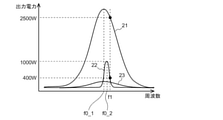
- FIG. 5 is a diagram illustrating the relationship between the frequency of the high frequency current supplied to the cooking cooker 100 according to the first embodiment and the output power.
- the horizontal axis of FIG. 5 indicates the frequency of the high frequency current supplied to the heating coil 6.
- the frequency of the high frequency current is the switching frequency of the switching element of the first drive circuit 11 or the second drive circuit 12.
- the vertical axis of FIG. 5 shows the electric power output by the heating coil 6, that is, the electric power input to the heating port 5.
- FIG. 5 shows that the output power of the heating coil 6 differs depending on the frequency of the high frequency current supplied to the heating coil 6.
- the characteristic 21 shows the resonance characteristic of the resonance circuit including the heating coil 6 and the first resonance capacitor 16 in the induction heating mode.
- the frequency at the apex of the characteristic 21 is the resonance frequency f0_1.
- the L value is the self-inductance value of the coil of the resonance circuit
- the C value is the capacitance value of the capacitor.
- the frequency of the high frequency current is controlled in a region higher than the resonance frequency f0_1.
- the control device 10 adjusts the output power by controlling the drive frequency of the first drive circuit 11.
- the drive frequency of the first drive circuit 11 is controlled in a range of approximately 17 kHz to 100 kHz.
- the inductance of the heating coil 6 is set to the first value by the inductance changing unit 13, and the second resonance capacitor 17 is disconnected from the heating coil 6 when the switch 18 is turned off. Then, a high frequency current is supplied to the heating coil 6 from the first drive circuit 11 that receives power from the commercial power source 50.
- a high frequency current is supplied from the second drive circuit 12 to the heating coil 6 by using the output from the storage battery 14 as described above.
- the storage battery 14 there is a storage battery 14 having an output voltage of about 24V DC to 96V DC.
- the maximum value of the bus voltage of the first drive circuit 11 is about 282V.
- the R value means the resistance value
- the L value means the inductance value
- the C value means the capacitance value.
- the inductance changing unit 13 changes the inductance value of the heating coil 6 to the second value, and the capacitance value of the resonance circuit of the heating coil 6 is changed to the first resonance capacitor 16 and the second. Let it be the total capacitance of the resonance capacitor 17. In this way, the characteristic 22 is obtained.
- FIG. 5 shows that the output power in the characteristic 22 is 400 W at the frequency f1.
- the frequency of the high frequency current supplied to the heating coil 6 is controlled according to the electric power required for the power receiving device.
- the output power peaks and an output power of about 1000 W can be obtained.
- the resonance frequency f0_1 in the characteristic 22 and the resonance frequency f0_1 in the characteristic 21 may be close to each other. That is, it is preferable that the first and second values of the inductance value of the heating coil 6 and the capacitance values of the first resonance capacitor 16 and the second resonance capacitor 17 are set so that f0_1 ⁇ f0_1. For example, the first portion 6a and the second portion 6b of the heating coil 6 have the same inductance value, and the first resonance capacitor 16 and the second resonance capacitor 17 have the same capacitance value. Then, f0_1 ⁇ f0_2.
- the range of the drive frequency of the first drive circuit 11 in the induction heating mode and the range of the drive frequency of the second drive circuit 12 in the power feeding mode are set to the range of 20 kHz to 100 kHz that can be used for induction heating. can do.
- the drive frequency bands of the first drive circuit 11 and the second drive circuit 12 are same in this way, the same type of element can be used in the first drive circuit 11 and the second drive circuit 12.
- the increase in the types of component parts of the elements used in the cooking cooker 100 is suppressed, so that the manufacturing cost of the cooking cooker 100 can be reduced.
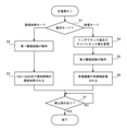
- FIG. 6 is a control flowchart of the cooking device 100 according to the first embodiment.
- the above-mentioned processing related to the change of the inductance value and the capacitance value is also described.
- the control flow shown in FIG. 6 is started.
- the inductance changing unit 13 has the inductance value of the heating coil 6 as the first value, and the switch 18 is in the off state.
- step S1 the operation mode is determined.
- the operation mode is determined, for example, based on the user's operation on the first operation unit 3a provided in the operation unit 3. Specifically, one of the induction heating mode and the power feeding mode is selected based on the user's operation on the first operation unit 3a, and the operation signal corresponding to the selected mode is transmitted from the first operation unit 3a to the control device. It is input to 10 and the operation mode corresponding to this operation signal is determined.
- the operation mode is determined based on the operation signal from the first operation unit 3a, but instead of or in addition to the operation signal from the first operation unit 3a, the top plate 1
- the control device 10 may determine whether the object to be heated 51 or the power receiving device is placed on the object by a known means.
- the first drive circuit 11 When the induction heating mode is determined in step S1, the first drive circuit 11 operates in step S2. As described above, the first drive circuit 11 is supplied with electric power from the commercial power source 50. When the first drive circuit 11 operates, a high frequency current is supplied to the heating coil 6 in step S3, and the object to be heated is induced and heated with an output power of 100 W to 3000 W. At this time, the characteristic 21 shown in FIG. 5 is obtained, and the frequency of the high frequency current is controlled in the range of the resonance frequency f0-1 or higher, so that the electric power corresponding to the frequency is applied to the object to be heated. The induction heating mode is continued until the stop instruction is input to the operation unit 3 in step S7 (step S7: YES).
- step S1 the inductance value and the capacitance value are changed in step S4. Specifically, the inductance changing unit 13 changes the inductance value of the heating coil 6 to a second value, which is a value smaller than the first value. Further, the switch 18 is turned on, and the capacitance value of the resonance circuit of the heating coil 6 is the total capacitance of the first resonance capacitor 16 and the second resonance capacitor 17 shown in FIG.
- step S5 the second drive circuit 12 operates. Power is supplied to the second drive circuit 12 from the storage battery 14 as described above.
- a high frequency current is supplied to the heating coil 6 in step S6, and non-contact power is supplied to the power receiving device.
- the characteristic 22 shown in FIG. 5 is obtained, and the frequency of the high frequency current is controlled in the range of the resonance frequency f0_2 or more, so that the power corresponding to the frequency is input to the power receiving device.
- the power supply mode is continued until the stop instruction is input to the operation unit 3 in step S7 (step S7: YES).
- the heating cooker 100 of the present embodiment is provided with an inductance changing unit 13 for changing the inductance value of the heating coil 6.
- the inductance changing unit 13 sets the inductance value of the heating coil 6 as the first value.
- the inductance changing unit 13 sets the inductance value of the heating coil 6 to the second value, which is a value smaller than the first value. ..
- the capacitance value of the series resonant circuit of the heating coil 6 is larger when the inductance value is the second value than when it is the first value.
- the Q value of the series resonance circuit of the heating coil 6, that is, the sharpness of resonance increases. Therefore, even when the voltage from the storage battery 14 is lower than that of the commercial power source 50, desired electric power corresponding to the frequency of the high frequency current supplied to the heating coil 6 can be input to the heating coil 6.
- the number of turns of the heating coil 6 when the high frequency current is supplied from the second drive circuit 12 to the heating coil 6 is such that the high frequency current is supplied from the first drive circuit 11 to the heating coil 6. It is smaller than the number of turns of the heating coil in the case.
- this change in the number of turns is realized by turning on the inductance changing portion 13 which is a switch connected in parallel with the second portion 6b of the heating coil 6.
- the Q value of the series resonance circuit of the heating coil 6, that is, the sharpness of resonance increases. Therefore, even when the voltage from the storage battery 14 is lower than that of the commercial power source 50, desired electric power corresponding to the frequency of the high frequency current supplied to the heating coil 6 can be input to the heating coil 6.
- the high frequency current is not supplied from the first drive circuit 11 to the heating coil 6 in the power feeding mode. That is, in a state where the power receiving device is placed on the heating port 5 of the top plate 1, high output for inducing heating the object to be heated 51 is not achieved. Therefore, a high output exceeding, for example, a rating of 1500 W is not applied to the power receiving device, and damage to the power receiving device due to the application of the high output can be avoided.
- Embodiment 2 an example in which an electric heater 8 is provided as a heating means for the object to be heated 51 in the heating port 5 will be described. In this embodiment, the differences from the first embodiment will be mainly described.
- FIG. 7 is a functional block diagram of the cooking device 100 according to the second embodiment.
- FIG. 7 also shows the planar positional relationship between the heating coil 6 and the electric heater 8.
- FIG. 8 is a functional block diagram of the cooking device 100 according to the second embodiment.
- FIG. 8 also shows the vertical positional relationship between the heating coil 6, the power recovery coil 7, and the electric heater 8 and the object to be heated 51.
- the heating cooker 100 of the present embodiment includes an electric heater 8 in addition to the heating coil 6 as a heating means for the object to be heated 51 in the heating port 5.
- the electric heater 8 is a resistance heating element such as a radiant heater.
- the electric heater 8 is arranged within the range of the heating port 5.
- the electric heater 8 of the present embodiment is annular and is arranged on the outer peripheral side of the heating coil 6.
- the arrangement of the electric heater 8 is not limited to that shown in FIG. 7.
- the electric heater 8 may be arranged between the inner annular coil and the outer annular coil of the heating coil 6 in which the conducting wire is wound in a double annular shape.
- a switching circuit 19 is provided on the output side of the second drive circuit 12.
- the switching circuit 19 is a circuit provided with a switch that selectively switches the supply destination of the high frequency current supplied from the second drive circuit 12 between the heating coil 6 and the electric heater 8.
- the switching circuit 19 is controlled by the control device 10.
- the storage battery 14 is charged in the induction heating mode, and the electric power supplied from the storage battery 14 is supplied to either the electric heater 8 or the heating coil 6 via the second drive circuit 12. While power is being supplied from the second drive circuit 12 to the electric heater 8, the electrical connection between the second drive circuit 12 and the heating coil 6 is disconnected. Further, while the electric power is supplied from the second drive circuit 12 to the heating coil 6, the electrical connection between the second drive circuit 12 and the electric heater 8 is released.
- FIG. 9 is a diagram illustrating a circuit configuration example of the cooking cooker 100 according to the second embodiment. It is the same as FIG. 4 except that the switching circuit 19, the electric heater 8 and the capacitor 20 are connected to the output side of the second drive circuit 12. A capacitor 20 is connected in series to the electric heater 8.
- the control device 10 of the heating cooker 100 of the present embodiment has a control mode called a heater heating mode in addition to the induction heating mode and the power supply mode.
- the heater heating mode is a control sequence in which an object to be heated 51 such as a pot placed on a heating port 5 is heated by an electric heater 8.
- the operation unit 3 of the present embodiment includes an input device for instructing the execution of the heater heating mode.
- a heated object 51 such as a pot is placed on the heating port 5.
- the switching circuit 19 connects the second drive circuit 12 and the electric heater 8.
- the high frequency current is also supplied to the electric heater 9.
- the electric heater 9 generates heat, and the object to be heated 51 above the heating port 5 is heated.
- the circuit constant is set so that the electric heater 9 obtains an output of about 300 W to 500 W mainly for keeping the heated object 51 warm. ..
- the heating cooker 100 of the present embodiment has an induction heating mode and a heater heating mode. Then, the storage battery 14 is charged in the induction heating mode, and the storage battery 14 is used to supply power to the electric heater 8 in the heater heating mode. Therefore, according to the present embodiment, the leakage magnetic flux generated in the induction heating mode can be effectively utilized for supplying power to the electric heater 8.
- the object to be heated 51 can be heated or kept warm without using the commercial power source 50, so that energy saving can be promoted.
- Embodiment 3 In the first embodiment and the second embodiment, the electric power supplied from the storage battery 14 is not used in the induction heating mode. In this embodiment, an example of using the electric power supplied from the storage battery 14 even in the induction heating mode will be described. In the present embodiment, the differences from the first embodiment and the second embodiment will be mainly described.
- the point that the first drive circuit 11 is not operated in the power feeding mode is the same as that of the first embodiment and the second embodiment.
- the heating cooker 100 of the present embodiment also has the induction heating mode shown in the first embodiment and the second embodiment.
- the present embodiment has a second induction heating mode in which the second drive circuit 12 is operated in addition to the first drive circuit 11 to supply a high frequency current to the heating coil 6.
- FIG. 10 is a control flowchart of the cooking device 100 according to the third embodiment.
- the flowchart shown in FIG. 10 differs from FIG. 6 in that it includes steps S1a, S8, and S9. The differences from FIG. 6 will be described below.
- the inductance changing unit 13 has the inductance value of the heating coil 6 as the first value, and the switch 18 is in the off state.
- the circuit configuration shown in FIG. 4 or 9 is adopted, and thus the circuit configuration will be described with reference to FIG. 4 or 9.
- step S1a the operation mode is determined.
- the mode selected in step S1a includes a second induction heating mode in addition to the induction heating mode and the feeding mode.
- the first operation unit 3a of the operation unit 3 of the present embodiment includes an input device for instructing the execution of the second induction heating mode, and the second operation unit 3a is based on the user's operation on the first operation unit 3a.
- the induction heating mode is selected.
- step S8 When the second induction heating mode is selected in step S1a, the first drive circuit 11 and the second drive circuit 12 operate in step S8.
- step S8 is executed, the inductance value of the heating coil 6 is in the initial state, that is, the first value state. Further, the switch 18 (see FIGS. 4 and 9) is in the off state.
- the first drive circuit 11 is supplied with electric power from the commercial power source 50
- the second drive circuit 12 is supplied with electric power from the storage battery 14.
- step S9 By operating the first drive circuit 11 and the second drive circuit 12, in step S9, a high frequency current is supplied to the heating coil 6 to induce and heat the object to be heated 51.
- FIG. 11 is a diagram illustrating the relationship between the frequency of the high frequency current supplied to the cooking cooker 100 according to the third embodiment and the output power.
- the characteristic 21 and the characteristic 23 are the resonance characteristics of the resonance circuit including the heating coil 6 and the first resonance capacitor 16.
- the L value is the inductance value of the heating coil 6 including the first portion 6a and the second portion 6b
- the C value is the capacitance value of the first resonance capacitor 16. Therefore, the frequency of the drive signal from the control device 10 to the first drive circuit 11 and the second drive circuit 12 is set to one type.
- a high frequency current having a frequency f2 is supplied to the heating coil 6 from the first drive circuit 11 and the second drive circuit 12. Due to the high frequency current of frequency f2, an output of, for example, 2000 W is obtained as shown in the characteristic 21, and in addition, an output of, for example, 200 W is obtained as shown in the characteristic 23. That is, in this example, an output of 2200 W is obtained in the second induction heating mode.
- the high frequency current from the second drive circuit 12, which receives power from the storage battery 14, is used to increase the output of the heating coil 6.
- the heating coil is composed of the first drive circuit 11 that receives power from the commercial power source 50 and the second drive circuit 12 that receives power from the storage battery 14.
- a high frequency current is supplied to 6. Therefore, it is possible to realize induction heating of the object to be heated 51 by receiving the power supplied from the storage battery 14 while suppressing the power supply from the commercial power source 50. Therefore, induction heating can be performed with low power consumption.
- This second induction heating mode can also be used as a peak cut for the use of the commercial power source 50.
- the second operation is performed.
- the power from the storage battery 14 is used using the induction heating mode.
- the maximum power consumption is determined to be 2000 W and it is desired to use power exceeding 2000 W
- the second induction heating mode is executed and the power from the storage battery 14 is used. By doing so, energy saving can be promoted.
- Embodiment 4 In this embodiment, a modified example of the power recovery coil 7 will be described. This embodiment can be combined with each of the first to third embodiments.
- FIG. 12 is a functional block diagram of the cooking device 100 according to the fourth embodiment.
- the power recovery coil 7 of the present embodiment is a copper foil coil provided on the substrate.
- the copper foil coil is formed on the substrate by printing. Then, this substrate is attached to the back surface of the top plate 1.
- the power recovery coil 7 provided on the substrate is located between the top plate 1 and the heating coil 6. As shown in FIG. 12, a power recovery coil 7 is arranged between the top plate 1 and the heating coil 6 in the vertical direction.
- the amount of magnetic flux interlinking with the power recovery coil 7 can be increased.
- a ferrite core may be provided on the back surface of the heating coil 6, that is, on the lower surface of the heating coil 6 in order to prevent magnetic flux leakage into the housing 2. Therefore, when the power recovery coil 7 is arranged on the lower surface of the heating coil 6 provided with the ferrite core, a part of the leakage magnetic flux generated from the heating coil 6 converges on the ferrite core, and the power recovery coil 7 is provided. The amount of magnetic flux interlinking with can be reduced.
- the power recovery coil 7 between the top plate 1 and the heating coil 6, that is, on the heating coil 6, power is supplied to the lower surface of the heating coil 6 provided with the ferrite core.
- the power recovery rate can be improved as compared with the case where the recovery coil 7 is provided.
- the manufacturing cost of the power recovery coil 7 can be reduced. Further, since the storage space of the power recovery coil 7 in the housing 2 can be reduced, the housing 2 can be miniaturized.
- Embodiment 5 In the first to fourth embodiments, an example in which the storage battery 14 is provided in the housing 2 has been described. In the present embodiment, the cooking cooker system 101 provided with the storage battery 14A outside the housing 2 of the cooking cooker 100A will be described. In this embodiment, the differences from the first to fourth embodiments will be mainly described.
- FIG. 13 is a functional block diagram of the cooking device system 101 according to the fifth embodiment.
- the cooking device system 101 includes a cooking device 100A and a storage battery 14A.
- As the cooking cooker 100A any one of the cooking cookers 100 described in the first to fourth embodiments, which is not provided with the storage battery 14, is adopted.
- the housing 2 is provided with a supply terminal 30 for connecting each of the rectifier circuit 15, the second drive circuit 12, and the storage battery 14A.
- the output end of the rectifier circuit 15 and the input end of the storage battery 14A are connected via the supply terminal 30, and the output from the rectifier circuit 15 is input to the storage battery 14A to charge the storage battery 14A. Further, the output end of the storage battery 14A and the input end of the second drive circuit 12 are connected via the supply terminal 30, and the electric power from the storage battery 14A is supplied to the second drive circuit 12.
- the configuration in which the storage battery 14A is charged in the process of inductively heating the object to be heated 51 in the induction heating mode and the charged electric power is used in the power supply mode or the second induction heating mode is as described in the first to third embodiments. ..
- the leakage magnetic flux generated in the induction heating mode can be effectively utilized for supplying power to the power receiving device or for induction heating cooking. Since power can be supplied to the power receiving device or induction heating can be performed without using the commercial power source 50 or in a state where the amount of the commercial power source 50 used is suppressed, energy saving can be promoted. Since the storage battery 14A is charged when cooking is performed in the induction heating mode of the heating cooker 100A, the user does not have to perform an operation for charging the storage battery 14A, and the user has to spend time and effort to charge the storage battery 14A. Can be omitted.
- the cooking cooker system 101 of the present embodiment is provided with the storage battery 14A, even if the commercial power source 50 is lost due to a power failure disaster, for example, power can be transmitted to the power receiving device, which is convenient for the user. It is possible to improve the sex.
- the cooking device system 101 of the present embodiment includes a storage battery 14A outside the housing 2 of the cooking device 100A.
- the storage battery 14A having a large charge capacity can be used.
- the storage battery 14A having a large charge capacity has a large size, it is not necessary to secure a space for accommodating the storage battery 14A in the housing 2, so that it is possible to avoid an increase in the size of the housing 2.
- the output voltage of the storage battery 14A can be increased.
- the bus voltage of the second drive circuit 12 becomes high, so that the amplitude of the vertical axis of the resonance characteristic shown in FIG.
- the output power from the second drive circuit 12 can be increased, and when the second induction heating mode is executed using the output from the second drive circuit 12, the power that can be input to the induction heating is increased. Can be made to. Further, by using the storage battery 14A having a large charge capacity, the output time of the electric power from the storage battery 14A can be lengthened. Since the output time of the power from the storage battery 14A becomes long, when the power supply mode is executed using the output from the second drive circuit 12, the number of times of power supply to the power receiving device can be increased, which is convenient for the user. The sex can be greatly improved.
- Embodiment 6 an example of charging the storage battery 14 with the output from the commercial power source 50 in addition to charging with the output from the power recovery coil 7 will be described.
- This embodiment can be combined with each of the first to fifth embodiments. Hereinafter, the differences from the first to fifth embodiments will be mainly described.
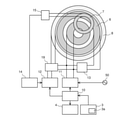
- FIG. 14 is a functional block diagram of the cooking device 100 according to the sixth embodiment.
- the positional relationship between the heating coil 6 and the power recovery coil 7 in the vertical direction and the object to be heated 51 are also shown.
- a rectifying step-down circuit 25 is provided in addition to the rectifying circuit 15 at the input stage of the storage battery 14.
- a switch 26 is provided between the rectifying circuit 15, the rectifying step-down circuit 25, and the storage battery 14.
- the rectifying step-down circuit 25 converts the AC voltage from the commercial power supply 50 into a DC voltage, lowers the DC voltage, and smoothes it.
- the rectifying step-down circuit 25 has, for example, a rectifying diode, a switch for switching the presence / absence of an output, and a smoothing capacitor.
- the storage battery 14 has a plurality of single batteries, that is, cells, but the voltage applied to the entire cell has an upper limit and a lower limit. Even if a voltage lower than the lower limit voltage is applied to the storage battery 14, the storage battery 14 cannot be charged, and if a voltage higher than the upper limit voltage is applied to the storage battery 14, the cell deteriorates.
- the AC voltage from the commercial power source 50 is higher than the AC voltage generated by the power recovery coil 7.
- the AC voltage from the commercial power source 50 is stepped down by the rectifying step-down circuit 25, and the step-down voltage is applied to the storage battery 14.
- the rectifying step-down circuit 25 may output a voltage reduced so as to be substantially the same as the voltage output from the rectifying circuit 15. It is desirable that the DC voltage completely smoothed by the rectifying step-down circuit 25 is input to the storage battery 14, but the DC voltage superimposed on the ripple may be applied to the storage battery 14.
- the switch 26 selectively connects the input stage of the storage battery 14 to one of the rectifying circuit 15 and the rectifying step-down circuit 25.
- the connection destination of the switch 26 is controlled by the control device 10.
- the switch 26 may be a mechanical switch or a semiconductor switch.
- the switch 26 connects the rectifying circuit 15 and the storage battery 14, the power recovery coil 7, the rectifying circuit 15, and the switch 26 form a first charging path for inputting power to the storage battery 14.
- the storage battery 14 is charged by the output from the power recovery coil 7.
- the switch 26 connects the rectifying step-down circuit 25 and the storage battery 14, the commercial power supply 50 and the storage battery 14 are connected.
- a second charging path for inputting electric power to the storage battery 14 is formed by the commercial power supply 50, the rectifying step-down circuit 25, and the switch 26, and the storage battery 14 is charged by the commercial power supply 50.
- the switch 26 connects the storage battery 14 and the rectifying step-down circuit 25, and the storage battery 14 is charged by the output of the commercial power source 50.
- the power receiving device of the heating port 5 is charged by the output from the storage battery 14, and at the same time, the storage battery 14 is charged from the commercial power source 50. Therefore, the output time of the electric power from the storage battery 14 can be lengthened, and the number of times of power supply to the power receiving device and the power supply time can be increased.
- the switch 26 connects the storage battery 14 and the rectifier circuit 15, and the storage battery 14 is charged by the output from the power recovery coil 7.
- an electromotive force is generated in the power recovery coil 7 due to the leakage magnetic flux from the heating coil 6, and the storage battery 14 is charged by this electromotive force. Therefore, according to the present embodiment, the leakage magnetic flux generated in the induction heating mode can be effectively utilized for charging the storage battery 14.
- the switch 26 connects the storage battery 14 and the rectifying step-down circuit 25, and the storage battery 14 is charged by the output of the commercial power source 50.
- electric power is supplied to the electric heater 8 (see FIGS. 7 and 8) by the output from the storage battery 14, and at the same time, the storage battery 14 is charged from the commercial power source 50. Therefore, the output time of the electric power from the storage battery 14 can be lengthened, and the heating time of the object to be heated 51 by the electric heater 8 can be increased.
- the switch 26 connects the storage battery 14 and the rectifier circuit 15, and the storage battery 14 is charged by the output from the power recovery coil 7.
- a high frequency current is supplied to the heating coil 6 from the first drive circuit 11 and the second drive circuit 12.
- the storage battery 14 is charged by the leakage magnetic flux from the heating coil 6, and high-frequency power is supplied from the charged storage battery 14 to the second drive circuit 12. Therefore, the supply time of the high frequency current from the second drive circuit 12 to the heating coil 6 can be lengthened. Therefore, it is possible to increase the time for inductive heating of the object to be heated 51 by receiving the power supplied from the storage battery 14 while suppressing the power supply from the commercial power source 50.
- the connection destination of the switch 26 may be switched according to the remaining amount of the storage battery 14. If the remaining amount of the storage battery 14 is equal to or higher than the threshold value, the switch 26 connects the storage battery 14 and the rectifier circuit 15, and charges the storage battery 14 by the output from the power recovery coil 7. Then, when the remaining amount of the storage battery 14 exceeds the threshold value and becomes small, the switch 26 connects the storage battery 14 and the rectifying step-down circuit 25, and charges the storage battery 14 by the output from the commercial power source 50. When the remaining amount of the storage battery 14 is low, the power supply time from the storage battery 14 to the heating coil 6 can be extended by charging the storage battery 14 from the commercial power source 50.
- the storage battery 14 can be supplied with power from the power recovery coil 7 and the commercial power source 50. Therefore, after using the electric power charged by the output from the electric power recovery coil 7, the storage battery 14 can be charged from the commercial power source 50, so that the time for using the electric power from the storage battery 14 can be extended.
Abstract
The present invention is equipped with: a top plate provided with a heating opening, which is the region where the object to be heated is placed; a heating coil provided below the heating opening; a power recovery coil for generating power by receiving magnetic flux leakage from the heating coil; a storage cell for storing power generated by the power recovery coil; a first drive circuit for receiving a power supply from a commercial power source, and supplying a high-frequency current to the heating coil; a second drive circuit for receiving a power supply from a storage cell, and supplying a high-frequency current to the heating coil; and a control device which has an induction heating mode for induction-heating an object to be heated which is placed in the heating opening by using the heating coil to which the high-frequency current is supplied from the first drive circuit, and also has a power supply mode for supplying power to the power-receiving device placed in the heating opening by using the heating coil to which the high-frequency current is supplied from the second drive circuit.
Description
本開示は、被加熱物を誘導加熱する加熱調理器及び加熱調理器システムに関する。
The present disclosure relates to a cooker and a cooker system that induces and heats an object to be heated.
被加熱物を誘導加熱する加熱コイルと、この加熱コイルに発生する磁束と鎖交する位置に配置された漏洩磁束回収コイルとを備え、漏洩磁束回収コイルに流れる電流を電力に変換して使用する加熱調理器が提案されている(たとえば、特許文献1参照)。
It is equipped with a heating coil that induces and heats the object to be heated and a leakage magnetic flux recovery coil that is arranged at a position that intersects with the magnetic flux generated in this heating coil, and is used by converting the current flowing through the leakage magnetic flux recovery coil into electric power. A heating cooker has been proposed (see, for example, Patent Document 1).
特許文献1に記載の加熱調理器では、漏洩磁束回収コイルに流れる電流から得た電力を、加熱コイルに高周波電流を供給する駆動回路の駆動電力として使用している。このような漏洩磁束として使われていなかった電力の利用は、省エネルギー化を図る上で有効であるので、漏洩磁束を受けて発生させた電力をさらに活用できる加熱調理器が望まれていた。
In the heating cooker described in Patent Document 1, the electric power obtained from the current flowing through the leakage flux recovery coil is used as the driving electric power of the drive circuit that supplies the high frequency current to the heating coil. Since the use of electric power that has not been used as such leakage magnetic flux is effective for energy saving, a cooking cooker that can further utilize the electric power generated by receiving the leakage magnetic flux has been desired.
本開示は、上記のような課題を背景とした技術であり、加熱コイルからの漏洩磁束を受けて発生させた電力を活用できる加熱調理器及び加熱調理器システムを提供するものである。
The present disclosure is a technology against the background of the above-mentioned problems, and provides a cooking cooker and a cooking cooker system that can utilize the electric power generated by receiving the leakage magnetic flux from the heating coil.
本開示に係る加熱調理器は、被加熱物が載置される領域である加熱口が設けられた天板と、前記加熱口の下に設けられた加熱コイルと、前記加熱コイルからの漏洩磁束を受けて電力を発生させる電力回収コイルと、前記電力回収コイルが発生させた電力を蓄える蓄電池と、商用電源から電力供給を受けて高周波電流を前記加熱コイルに供給する第1駆動回路と、前記蓄電池から電力供給を受けて高周波電流を前記加熱コイルに供給する第2駆動回路と、前記加熱口に載置された被加熱物を、前記第1駆動回路から高周波電流を供給された前記加熱コイルで誘導加熱する誘導加熱モードと、前記加熱口に載置された受電機器に、前記第2駆動回路から高周波電流が供給された前記加熱コイルで給電する給電モードとを有する制御装置とを備えたものである。
本開示に係る加熱調理器システムは、被加熱物が載置される領域である加熱口が設けられた天板と、前記加熱口の下に設けられた加熱コイルと、前記加熱コイルを収容する筐体と、前記加熱コイルからの漏洩磁束を受けて電力を発生させる電力回収コイルと、を備えた加熱調理器と、前記筐体の外に配置され、前記電力回収コイルが発生させた電力を蓄える蓄電池と、を備えた加熱調理器システムであって、前記加熱調理器は、商用電源から電力供給を受けて高周波電流を前記加熱コイルに供給する第1駆動回路と、前記蓄電池から電力供給を受けて高周波電流を前記加熱コイルに供給する第2駆動回路と、前記加熱口に載置された被加熱物を、前記第1駆動回路から高周波電流を供給された前記加熱コイルで誘導加熱する誘導加熱モードと、前記加熱口に載置された受電機器に、前記第2駆動回路から高周波電流が供給された前記加熱コイルで給電する給電モードとを有する制御装置とを備えたものである。 The heating cooker according to the present disclosure includes a top plate provided with a heating port in which an object to be heated is placed, a heating coil provided under the heating port, and a leakage current from the heating coil. A power recovery coil that receives power to generate power, a storage battery that stores the power generated by the power recovery coil, a first drive circuit that receives power from a commercial power source and supplies a high-frequency current to the heating coil, and the above. The second drive circuit that receives power from the storage battery and supplies a high-frequency current to the heating coil, and the heating coil to which the high-frequency current is supplied from the first drive circuit to the object to be heated placed on the heating port. The power receiving device mounted on the heating port is provided with a control device having an induced heating mode for inductive heating and a power feeding mode in which a high-frequency current is supplied from the second drive circuit by the heating coil. It is a thing.
The heating cooker system according to the present disclosure accommodates a top plate provided with a heating port, which is an area on which an object to be heated is placed, a heating coil provided under the heating port, and the heating coil. A heating cooker provided with a housing and a power recovery coil that receives a leakage magnetic flux from the heating coil to generate power, and power generated by the power recovery coil arranged outside the housing. A heating cooker system including a storage battery for storing, wherein the heating cooker receives power from a commercial power source and supplies high-frequency current to the heating coil, and power is supplied from the storage battery. A second drive circuit that receives and supplies a high-frequency current to the heating coil and an object to be heated placed on the heating port are induced and heated by the heating coil to which a high-frequency current is supplied from the first drive circuit. It is provided with a control device having a heating mode and a power feeding mode in which a power receiving device mounted on the heating port is supplied with a power supply by the heating coil to which a high frequency current is supplied from the second drive circuit.
本開示によれば、加熱コイルからの漏洩磁束を受けて発生させた電力を、加熱口に載置された受電機器への給電に利用することができる。
According to the present disclosure, the electric power generated by receiving the leakage magnetic flux from the heating coil can be used to supply power to the power receiving device mounted on the heating port.
以下、本開示に係る加熱調理器の実施の形態を、図面を参照して説明する。以下の実施の形態は例示であり、実施の形態に示される事項をその趣旨を逸脱しない範囲で種々に変形することが可能である。また、以下の各実施の形態に示す構成を互いに組み合わせうる。また、以下の説明において、理解を容易にするために方向を表す用語(例えば「上」、「下」、「右」、「左」、「前」、「後」など)を適宜用いるが、これらは説明のためのものであって、本開示を限定するものではない。また、各図において、同一の符号を付したものは、同一の又はこれに相当するものであり、これは明細書の全文において共通している。なお、各図面では、各構成部材の相対的な寸法関係又は形状等が実際のものとは異なる場合がある。
Hereinafter, embodiments of the cooking device according to the present disclosure will be described with reference to the drawings. The following embodiments are examples, and the matters shown in the embodiments can be variously modified without departing from the spirit. In addition, the configurations shown in the following embodiments can be combined with each other. Further, in the following description, terms indicating directions (for example, "top", "bottom", "right", "left", "front", "rear", etc.) are appropriately used for ease of understanding. These are for illustration purposes only and are not intended to limit this disclosure. Further, in each figure, those having the same reference numerals are the same or equivalent thereof, which are common to the whole text of the specification. In each drawing, the relative dimensional relationship or shape of each constituent member may differ from the actual one.
実施の形態1.
図1は、実施の形態1に係る加熱調理器100の外観斜視図である。加熱調理器100は、鍋などの被加熱物が載置される天板1と、天板1の下に設けられた筐体2とを有する。筐体2には、使用者の操作入力を受け付けるボタン又はスイッチ等を有する操作部3が設けられている。また、加熱調理器100には、加熱調理器100の動作状態及び使用者の操作入力の内容を表示する表示部4が設けられている。Embodiment 1.
FIG. 1 is an external perspective view of thecooking device 100 according to the first embodiment. The heating cooker 100 has a top plate 1 on which an object to be heated such as a pot is placed, and a housing 2 provided under the top plate 1. The housing 2 is provided with an operation unit 3 having a button, a switch, or the like for receiving an operation input of a user. Further, the cooking cooker 100 is provided with a display unit 4 for displaying the operating state of the cooking cooker 100 and the contents of the operation input of the user.
図1は、実施の形態1に係る加熱調理器100の外観斜視図である。加熱調理器100は、鍋などの被加熱物が載置される天板1と、天板1の下に設けられた筐体2とを有する。筐体2には、使用者の操作入力を受け付けるボタン又はスイッチ等を有する操作部3が設けられている。また、加熱調理器100には、加熱調理器100の動作状態及び使用者の操作入力の内容を表示する表示部4が設けられている。
FIG. 1 is an external perspective view of the
さらに本実施の形態の操作部3は、後述する誘導加熱モードと給電モードのいずれかの実行を指示する第1操作部3aを含んでいる。第1操作部3aは、誘導加熱モードの実行を指示する入力装置と、給電モードの実行を指示する入力装置と、をそれぞれ備えていてもよいし、誘導加熱モードと給電モードのいずれかを択一的に選択する切り替え装置を備えていてもよい。なお、操作部3及び表示部4の具体的構成は、図示したものに限定されない。
Further, the operation unit 3 of the present embodiment includes a first operation unit 3a for instructing execution of either the induction heating mode or the power supply mode, which will be described later. The first operation unit 3a may include an input device for instructing the execution of the induction heating mode and an input device for instructing the execution of the power supply mode, respectively, and either the induction heating mode or the power supply mode can be selected. It may be provided with a switching device for selecting uniformly. The specific configurations of the operation unit 3 and the display unit 4 are not limited to those shown in the drawings.
天板1は、3つの加熱口5を有している。加熱口5は、鍋などの被加熱物が載置される領域である。天板1には、加熱口5が印刷によって示されている。図1では、説明のため、1つの加熱口5に設けられた加熱コイル6を破線で示している。3つの加熱口5のすべてあるいは一部に、以下で説明する加熱コイル6を設けることができる。
The top plate 1 has three heating ports 5. The heating port 5 is an area on which a heated object such as a pot is placed. A heating port 5 is printed on the top plate 1. In FIG. 1, for the sake of explanation, the heating coil 6 provided in one heating port 5 is shown by a broken line. The heating coils 6 described below can be provided in all or part of the three heating ports 5.
図2は、実施の形態1に係る加熱調理器100の機能ブロック図である。図2では、加熱コイル6と電力回収コイル7の平面的な位置関係を併せて図示している。図3は、実施の形態1に係る加熱調理器100の機能ブロック図である。図3では、加熱コイル6と電力回収コイル7の上下の位置関係及び被加熱物51を併せて図示している。また、図2及び図3には、商用電源50も図示している。図2及び図3では、図1に示した加熱調理器100の3つの加熱口5のうちの一つに対応した構成のみを示している。
FIG. 2 is a functional block diagram of the cooking device 100 according to the first embodiment. FIG. 2 also shows the planar positional relationship between the heating coil 6 and the power recovery coil 7. FIG. 3 is a functional block diagram of the cooking device 100 according to the first embodiment. FIG. 3 also shows the vertical positional relationship between the heating coil 6 and the power recovery coil 7 and the object to be heated 51. Further, FIGS. 2 and 3 also show a commercial power supply 50. 2 and 3 show only the configuration corresponding to one of the three heating ports 5 of the cooking cooker 100 shown in FIG. 1.
加熱調理器100は、加熱コイル6と、電力回収コイル7と、制御装置10と、第1駆動回路11と、第2駆動回路12と、蓄電池14とを備える。本実施の形態の加熱調理器100は、さらに、加熱コイル6のインダクタンス値を変更するインダクタンス変更部13を備える。
The cooking cooker 100 includes a heating coil 6, a power recovery coil 7, a control device 10, a first drive circuit 11, a second drive circuit 12, and a storage battery 14. The heating cooker 100 of the present embodiment further includes an inductance changing unit 13 that changes the inductance value of the heating coil 6.
加熱コイル6は、導線が環状に巻き回されて形成されている。加熱コイル6は、本実施の形態では、1つの加熱口5に対して1つ設けられている。加熱コイル6は、加熱口5に載置される被加熱物51の誘導加熱と、加熱口5に載置される受電機器への給電と、に使用される。
The heating coil 6 is formed by winding a conducting wire in an annular shape. In this embodiment, one heating coil 6 is provided for one heating port 5. The heating coil 6 is used for induction heating of the object to be heated 51 placed on the heating port 5 and for supplying power to the power receiving device mounted on the heating port 5.
電力回収コイル7は、導線が環状に巻き回されて形成されている。なお、電力回収コイル7の形状は、環状に限定されない。電力回収コイル7は、加熱コイル6から発生する磁束と鎖交する位置に配置される。本実施の形態の電力回収コイル7は、図2に示すように平面的に加熱コイル6と重なる位置であって、図3に示すように加熱コイル6の下側に配置されている。
The power recovery coil 7 is formed by winding a conducting wire in an annular shape. The shape of the power recovery coil 7 is not limited to the annular shape. The power recovery coil 7 is arranged at a position where it intersects with the magnetic flux generated from the heating coil 6. The power recovery coil 7 of the present embodiment is positioned so as to overlap the heating coil 6 in a plane as shown in FIG. 2, and is arranged below the heating coil 6 as shown in FIG.
電力回収コイル7には、整流回路15を介して蓄電池14が接続されている。整流回路15は、電力回収コイル7により生成された交流電圧を直流電圧に変換して平滑化する。整流回路15は、例えば整流ダイオードと平滑コンデンサとを有している。なお、整流回路15によって完全平滑された直流電圧が蓄電池14に入力されるのが望ましいが、リプル重畳された直流電圧が蓄電池14に印加される構成であってもよい。
A storage battery 14 is connected to the power recovery coil 7 via a rectifier circuit 15. The rectifier circuit 15 converts the AC voltage generated by the power recovery coil 7 into a DC voltage and smoothes it. The rectifier circuit 15 has, for example, a rectifier diode and a smoothing capacitor. It is desirable that the DC voltage completely smoothed by the rectifier circuit 15 is input to the storage battery 14, but the DC voltage superimposed on the ripple may be applied to the storage battery 14.
蓄電池14は、整流回路15によって平滑化された電力を蓄電する。蓄電池14は、例えばリチウム電池などの二次電池である。
The storage battery 14 stores electric power smoothed by the rectifier circuit 15. The storage battery 14 is a secondary battery such as a lithium battery.
制御装置10は、操作部3から入力される操作信号に基づいて、第1駆動回路11、第2駆動回路12、インダクタンス変更部13及び表示部4を制御する。制御装置10は、専用のハードウェア、またはメモリに格納されるプログラムを実行するCPU(Central Processing Unit)で構成される。制御装置10がCPUの場合、制御装置10が実行する各機能は、ソフトウェア、ファームウェア、またはソフトウェアとファームウェアとの組み合わせにより実現される。ソフトウェアやファームウェアはプログラムとして記述され、メモリに格納される。CPUは、メモリに格納されたプログラムを読み出して実行することにより、制御装置10の各機能を実現する。ここで、メモリは、例えば、RAM、ROM、フラッシュメモリ、EPROM、EEPROM等の、不揮発性または揮発性の半導体メモリである。
The control device 10 controls the first drive circuit 11, the second drive circuit 12, the inductance changing unit 13, and the display unit 4 based on the operation signal input from the operation unit 3. The control device 10 is composed of dedicated hardware or a CPU (Central Processing Unit) that executes a program stored in a memory. When the control device 10 is a CPU, each function executed by the control device 10 is realized by software, firmware, or a combination of software and firmware. Software and firmware are written as programs and stored in memory. The CPU realizes each function of the control device 10 by reading and executing a program stored in the memory. Here, the memory is a non-volatile or volatile semiconductor memory such as RAM, ROM, flash memory, EPROM, EEPROM and the like.
第1駆動回路11は、商用電源50から入力される交流電流を高周波電流に変換して出力するインバータ回路である。第1駆動回路11から出力される高周波電流は、加熱コイル6に供給される。
The first drive circuit 11 is an inverter circuit that converts an alternating current input from the commercial power supply 50 into a high frequency current and outputs it. The high frequency current output from the first drive circuit 11 is supplied to the heating coil 6.
第2駆動回路12は、蓄電池14から入力される直流電流を高周波電流に変換して出力するインバータ回路である。第2駆動回路12から出力される高周波電流は、加熱コイル6に供給される。
The second drive circuit 12 is an inverter circuit that converts the direct current input from the storage battery 14 into a high frequency current and outputs it. The high frequency current output from the second drive circuit 12 is supplied to the heating coil 6.
インダクタンス変更部13は、加熱コイル6のインダクタンス値を、第1値と、第1値よりも小さい値である第2値との間で切り換える。インダクタンス変更部13の具体的な構成例は、後述する。
The inductance changing unit 13 switches the inductance value of the heating coil 6 between the first value and the second value, which is a value smaller than the first value. A specific configuration example of the inductance changing unit 13 will be described later.
次に、本実施の形態の加熱調理器100の動作概要を説明する。本実施の形態の加熱調理器100の制御装置10は、誘導加熱モードと給電モードという2つの制御モードを有している。誘導加熱モードは、加熱口5に載置された鍋などの被加熱物51を誘導加熱する制御モードである。給電モードは、加熱口5に載置された受電機器に非接触給電するための制御モードである。
Next, an outline of the operation of the cooking device 100 of the present embodiment will be described. The control device 10 of the heating cooker 100 of the present embodiment has two control modes, an induction heating mode and a power feeding mode. The induction heating mode is a control mode for inducing heating an object to be heated 51 such as a pot placed on the heating port 5. The power supply mode is a control mode for non-contact power supply to the power receiving device mounted on the heating port 5.
誘導加熱モードが実行される場合には、加熱口5の上には、鍋などの被加熱物51が載置されている。誘導加熱モードにおいて、加熱コイル6に高周波電流が供給されると、加熱コイル6から磁束が発生し、加熱口5に載置され磁束と鎖交する被加熱物51に渦電流が発生する。この渦電流によって生じるジュール熱により、被加熱物51が高温化する。このようにして、加熱口5に載置された被加熱物51が誘導加熱される。誘導加熱モードでは、商用電源50からの電力が、第1駆動回路11を介して加熱コイル6に供給される。
When the induction heating mode is executed, a heated object 51 such as a pot is placed on the heating port 5. In the induction heating mode, when a high-frequency current is supplied to the heating coil 6, a magnetic flux is generated from the heating coil 6, and an eddy current is generated in the object to be heated 51 placed on the heating port 5 and interlinking with the magnetic flux. The Joule heat generated by this eddy current raises the temperature of the object to be heated 51. In this way, the object to be heated 51 placed on the heating port 5 is induced and heated. In the induction heating mode, electric power from the commercial power source 50 is supplied to the heating coil 6 via the first drive circuit 11.
加熱コイル6から発生する磁束の一部は、電力回収コイル7と鎖交する。電力回収コイル7に磁束が鎖交すると、電力回収コイル7には、磁束の変化を打ち消す方向に起電力が発生し、電流が流れる。電力回収コイル7に発生した起電力は、整流回路15によって整流され、蓄電池14を充電する。このように、誘導加熱モードでは、被加熱物51が誘導加熱されるのと同時に、蓄電池14への充電が行われる。
A part of the magnetic flux generated from the heating coil 6 interlinks with the power recovery coil 7. When the magnetic flux is interlinked with the power recovery coil 7, an electromotive force is generated in the power recovery coil 7 in a direction that cancels the change in the magnetic flux, and a current flows through the power recovery coil 7. The electromotive force generated in the power recovery coil 7 is rectified by the rectifier circuit 15 to charge the storage battery 14. As described above, in the induction heating mode, the storage battery 14 is charged at the same time as the induction heating of the object to be heated 51.
給電モードが実行される場合には、加熱口5の上には、受電機器が載置されている。受電機器は、受電コイルを備え、受電コイルに流れる電流を電力として利用する機器である。給電モードにおいて、加熱コイル6に高周波電流が供給されると、加熱コイル6から磁束が発生し、発生した磁束によって受電機器の受電コイルには電磁誘導による起電力が発生する。受電機器の受電コイルに流れた高周波電流は、受電機器にて利用される。給電モードでは、蓄電池14からの電力が、第2駆動回路12を介して加熱コイル6に供給される。
When the power supply mode is executed, a power receiving device is placed on the heating port 5. The power receiving device is a device provided with a power receiving coil and using the current flowing through the power receiving coil as electric power. When a high-frequency current is supplied to the heating coil 6 in the power feeding mode, a magnetic flux is generated from the heating coil 6, and the generated magnetic flux generates an electromotive force due to electromagnetic induction in the power receiving coil of the power receiving device. The high frequency current flowing through the power receiving coil of the power receiving device is used in the power receiving device. In the power feeding mode, the electric power from the storage battery 14 is supplied to the heating coil 6 via the second drive circuit 12.
加熱口5に設けられた加熱コイル6が、誘導加熱モードと給電モードの両方で使用され、加熱口5は誘導加熱される被加熱物の載置場所であるとともに、受電機器の載置場所でもある。したがって、使用者は、被加熱物及び受電機器の載置場所に迷うことがなく、利便性が高い。
The heating coil 6 provided in the heating port 5 is used in both the induction heating mode and the power feeding mode, and the heating port 5 is a place where the object to be heated to be induced is placed and also a place where the power receiving device is placed. be. Therefore, the user does not get lost in the place where the heated object and the power receiving device are placed, which is highly convenient.
このように、本実施の形態の加熱調理器100は、誘導加熱モードと給電モードとを有する。そして、誘導加熱モードにおいて蓄電池14に充電し、給電モードにおいては蓄電池14を用いて受電機器への給電を行う。したがって、本実施の形態によれば、誘導加熱モードにおいて生じた漏洩磁束を、受電機器への給電に有効活用することができる。商用電源50の出力を使うことなく、受電機器ヘの送電が行えるので、省エネルギー化を促進できる。また、加熱調理器100の誘導加熱モードで加熱調理が行われているときに、蓄電池14は充電されるので、使用者は蓄電池14の充電のための操作を行わなくてよく、使用者の充電の手間を省くことができる。また、本実施の形態の加熱調理器100は蓄電池14を備えたので、例えば停電災害により商用電源50が消失した場合であっても、受電機器への送電が可能であり、使用者の利便性を向上させることができる。
As described above, the heating cooker 100 of the present embodiment has an induction heating mode and a power feeding mode. Then, the storage battery 14 is charged in the induction heating mode, and the storage battery 14 is used to supply power to the power receiving device in the power supply mode. Therefore, according to the present embodiment, the leakage magnetic flux generated in the induction heating mode can be effectively utilized for supplying power to the power receiving device. Since power can be transmitted to the power receiving device without using the output of the commercial power source 50, energy saving can be promoted. Further, since the storage battery 14 is charged when cooking is performed in the induction heating mode of the heating cooker 100, the user does not have to perform an operation for charging the storage battery 14, and the user does not have to perform the operation for charging the storage battery 14. You can save the trouble of. Further, since the cooking device 100 of the present embodiment is provided with the storage battery 14, even if the commercial power source 50 is lost due to a power failure disaster, for example, power can be transmitted to the power receiving device, which is convenient for the user. Can be improved.
例えば、受電機器がスマートフォンであり、給電モードにおいてスマートフォンへの充電が行われる場合、受電可能な電力は10W程度となりうる。したがって、仮に、蓄電池14の充電容量の上限のために、蓄電池14の出力電圧が商用電源50と比べて小さい場合であっても、漏洩磁束から得た電力を受電機器への給電に十分活用できる。
For example, when the power receiving device is a smartphone and the smartphone is charged in the power supply mode, the power that can be received can be about 10 W. Therefore, even if the output voltage of the storage battery 14 is smaller than that of the commercial power source 50 due to the upper limit of the charge capacity of the storage battery 14, the power obtained from the leakage magnetic flux can be sufficiently utilized for supplying power to the power receiving device. ..
ここで、本実施の形態のように加熱口5に載置された被加熱物51を一対一で誘導加熱する加熱コイル6は、調理における利便性向上のため、高出力での誘導加熱が可能なインダクタンス値が求められる。誘導加熱調理に求められる出力は、100W~3000W程度である。そうすると、このような高出力が可能な大きなインダクタンス値を備えた加熱コイル6を、給電モードで使用する場合、受電機器によっては加熱コイル6のインダクタンス値が大きすぎる、すなわち出力が大きすぎる、ということもありうる。本実施の形態では、このような事情に鑑み、加熱コイル6のインダクタンス値を変更するインダクタンス変更部13を備えている。
Here, the heating coil 6 that induces and heats the object to be heated 51 placed on the heating port 5 on a one-to-one basis as in the present embodiment can perform induction heating at a high output in order to improve convenience in cooking. Inductance value is required. The output required for induction cooking is about 100 W to 3000 W. Then, when the heating coil 6 having such a large inductance value capable of high output is used in the power feeding mode, the inductance value of the heating coil 6 is too large, that is, the output is too large depending on the power receiving device. There can also be. In view of such circumstances, the present embodiment includes an inductance changing unit 13 that changes the inductance value of the heating coil 6.
図4は、実施の形態1に係る加熱調理器100の回路構成例を説明する図である。図4で例示する第1駆動回路11は、スイッチング素子111とスイッチング素子112とを有するハーフブリッジ型インバータである。スイッチング素子111及びスイッチング素子112は、商用電源50に接続された電源ラインとGNDラインとの間に直列に接続されている。スイッチング素子111とスイッチング素子112との間に、第1駆動回路11の出力点がある。第1駆動回路11の出力点は、加熱コイル6に接続されている。
FIG. 4 is a diagram illustrating a circuit configuration example of the cooking cooker 100 according to the first embodiment. The first drive circuit 11 illustrated in FIG. 4 is a half-bridge type inverter having a switching element 111 and a switching element 112. The switching element 111 and the switching element 112 are connected in series between the power supply line connected to the commercial power supply 50 and the GND line. There is an output point of the first drive circuit 11 between the switching element 111 and the switching element 112. The output point of the first drive circuit 11 is connected to the heating coil 6.
図4で例示する第2駆動回路12は、スイッチング素子121とスイッチング素子122とを有するハーフブリッジ型インバータである。スイッチング素子121及びスイッチング素子122は、蓄電池14及び整流回路15に接続された電源ラインとGNDラインとの間に直列に接続されている。スイッチング素子121とスイッチング素子122との間に、第2駆動回路12の出力点がある。第2駆動回路12の出力点は、加熱コイル6に接続されている。
The second drive circuit 12 illustrated in FIG. 4 is a half-bridge type inverter having a switching element 121 and a switching element 122. The switching element 121 and the switching element 122 are connected in series between the power supply line connected to the storage battery 14 and the rectifier circuit 15 and the GND line. There is an output point of the second drive circuit 12 between the switching element 121 and the switching element 122. The output point of the second drive circuit 12 is connected to the heating coil 6.
なお、ここでは第1駆動回路11及び第2駆動回路12がハーフブリッジ型インバータである例を示したが、インバータ回路の具体的構成は例示したものに限定されない。
Although the example in which the first drive circuit 11 and the second drive circuit 12 are half-bridge type inverters is shown here, the specific configuration of the inverter circuit is not limited to the example.
制御装置10は、本実施の形態では、第1駆動回路11と第2駆動回路12の何れかを排他的に動作させる。制御装置10は、第1駆動回路11を動作させる場合には、スイッチング素子111とスイッチング素子112とを交互にオンさせる。制御装置10は、第2駆動回路12を動作させる場合には、スイッチング素子121とスイッチング素子122とを交互にオンさせる。
In the present embodiment, the control device 10 exclusively operates either the first drive circuit 11 or the second drive circuit 12. When the first drive circuit 11 is operated, the control device 10 alternately turns on the switching element 111 and the switching element 112. When the second drive circuit 12 is operated, the control device 10 alternately turns on the switching element 121 and the switching element 122.
本実施の形態のインダクタンス変更部13は、加熱コイル6を構成する導線の一部と並列に接続されたスイッチである。加熱コイル6は、前述のとおり導線が環状に巻かれて構成されているが、この環状に巻かれた導線の一部に対して並列に、スイッチであるインダクタンス変更部13が接続されている。加熱コイル6のうち、インダクタンス変更部13が並列に接続されていない部分を第1部分6a、インダクタンス変更部13が並列に接続されている部分を第2部分6bと称する。第1部分6aとインダクタンス変更部13とは、直列に接続されている。本実施の形態では、第1部分6aは加熱口5の中央部に配置されており、第2部分6bは第1部分6aの外周側に配置されている。ここで、インダクタンス変更部13を構成するスイッチと第2部分6bとを接続する電線のインダクタンスは、第2部分6bのインダクタンスよりも小さい。
The inductance changing unit 13 of the present embodiment is a switch connected in parallel with a part of the conducting wire constituting the heating coil 6. As described above, the heating coil 6 is configured by winding a conducting wire in an annular shape, and an inductance changing portion 13 which is a switch is connected in parallel to a part of the conducting wire wound in the annular shape. The portion of the heating coil 6 in which the inductance changing portion 13 is not connected in parallel is referred to as a first portion 6a, and the portion in which the inductance changing portion 13 is connected in parallel is referred to as a second portion 6b. The first portion 6a and the inductance changing portion 13 are connected in series. In the present embodiment, the first portion 6a is arranged in the central portion of the heating port 5, and the second portion 6b is arranged on the outer peripheral side of the first portion 6a. Here, the inductance of the electric wire connecting the switch constituting the inductance changing portion 13 and the second portion 6b is smaller than the inductance of the second portion 6b.
本実施の形態のインダクタンス変更部13は、供給された高周波電流が、第2部分6bを迂回して第1部分6aに流れるようにするための迂回経路を構成する。インダクタンス変更部13のスイッチがオンすると、オン状態のスイッチにより形成される電流経路を高周波電流が流れ、高周波電流は第2部分6bには流れない、あるいはほとんど流れない。インダクタンス変更部13のスイッチがオン状態のとき、加熱コイル6の巻き数は第1部分6aの巻き数と実質的に等しくなり、スイッチがオフ状態のとき、加熱コイル6の巻き数は第1部分6aと第2部分6bの巻き数の合計となる。このように、本実施の形態のインダクタンス変更部13は、加熱コイル6の巻き数を変更することによって、加熱コイル6のインダクタンス値を変更する。インダクタンス変更部13のスイッチがオフ状態のときの加熱コイル6のインダクタンス値を第1値と称し、インダクタンス変更部13のスイッチがオン状態のときの加熱コイル6のインダクタンス値を第2値と称する。
The inductance changing unit 13 of the present embodiment constitutes a detour path for allowing the supplied high-frequency current to bypass the second portion 6b and flow to the first portion 6a. When the switch of the inductance changing unit 13 is turned on, a high frequency current flows through the current path formed by the switch in the on state, and the high frequency current does not flow or hardly flows in the second portion 6b. When the switch of the inductance changing unit 13 is on, the number of turns of the heating coil 6 is substantially equal to the number of turns of the first portion 6a, and when the switch is off, the number of turns of the heating coil 6 is the first portion. It is the total number of turns of 6a and the second part 6b. In this way, the inductance changing unit 13 of the present embodiment changes the inductance value of the heating coil 6 by changing the number of turns of the heating coil 6. The inductance value of the heating coil 6 when the switch of the inductance changing unit 13 is in the off state is referred to as a first value, and the inductance value of the heating coil 6 when the switch of the inductance changing unit 13 is in the on state is referred to as a second value.
加熱コイル6には、第1共振コンデンサ16が直列に接続されている。加熱コイル6と第1共振コンデンサ16とで、直列共振回路が形成される。
A first resonance capacitor 16 is connected in series to the heating coil 6. A series resonance circuit is formed by the heating coil 6 and the first resonance capacitor 16.
第1共振コンデンサ16には、第2共振コンデンサ17及びスイッチ18が接続されている。直列に接続された第2共振コンデンサ17とスイッチ18とからなる回路が、第1共振コンデンサ16に対して並列に接続されている。スイッチ18がオン状態になると、加熱コイル6と、第1共振コンデンサ16及び第2共振コンデンサ17とで、直列共振回路が形成される。スイッチ18がオフ状態になると、加熱コイル6と第1共振コンデンサ16とで、共振回路が形成される。すなわち、スイッチ18のオン状態とオフ状態とが切り換わることで、共振回路の共振コンデンサ容量が切り換えられる。
The second resonance capacitor 17 and the switch 18 are connected to the first resonance capacitor 16. A circuit including a second resonance capacitor 17 and a switch 18 connected in series is connected in parallel to the first resonance capacitor 16. When the switch 18 is turned on, the heating coil 6 and the first resonance capacitor 16 and the second resonance capacitor 17 form a series resonance circuit. When the switch 18 is turned off, a resonance circuit is formed by the heating coil 6 and the first resonance capacitor 16. That is, by switching between the on state and the off state of the switch 18, the resonance capacitor capacity of the resonance circuit is switched.
なお、図4ではスイッチ18は半導体式のスイッチとして図示されているが、スイッチ18は機械式のスイッチであってもよい。また、スイッチ18は、制御装置10によってオン状態とオフ状態とが切り換えられる。
Although the switch 18 is shown as a semiconductor type switch in FIG. 4, the switch 18 may be a mechanical switch. Further, the switch 18 is switched between an on state and an off state by the control device 10.
図5は、実施の形態1に係る加熱調理器100に供給される高周波電流の周波数と出力電力の関係を説明する図である。図5の横軸は、加熱コイル6に供給される高周波電流の周波数を示す。高周波電流の周波数は、第1駆動回路11又は第2駆動回路12のスイッチング素子のスイッチング周波数である。図5の縦軸は、加熱コイル6によって出力される電力、すなわち加熱口5に投入される電力を示している。図5では、加熱コイル6に供給される高周波電流の周波数によって加熱コイル6の出力電力が異なることを示している。
FIG. 5 is a diagram illustrating the relationship between the frequency of the high frequency current supplied to the cooking cooker 100 according to the first embodiment and the output power. The horizontal axis of FIG. 5 indicates the frequency of the high frequency current supplied to the heating coil 6. The frequency of the high frequency current is the switching frequency of the switching element of the first drive circuit 11 or the second drive circuit 12. The vertical axis of FIG. 5 shows the electric power output by the heating coil 6, that is, the electric power input to the heating port 5. FIG. 5 shows that the output power of the heating coil 6 differs depending on the frequency of the high frequency current supplied to the heating coil 6.
図5において、特性21は、誘導加熱モードにおける加熱コイル6と第1共振コンデンサ16とからなる共振回路の共振特性を示している。特性21の頂点における周波数が、共振周波数f0_1である。ここで一般に、共振回路の共振周波数f0は、f0=1/2π√(L値×C値)で表される。L値は、共振回路のコイルの自己インダクタンス値であり、C値はコンデンサのキャパシタンス値である。加熱コイル6に供給される高周波電流の周波数が共振周波数に近づくと、インピーダンスが小さくなるため、出力電力が大きくなる。なお、被加熱物51が磁性材料で構成されている場合、共振周波数f0は約17kHzに設定される。
In FIG. 5, the characteristic 21 shows the resonance characteristic of the resonance circuit including the heating coil 6 and the first resonance capacitor 16 in the induction heating mode. The frequency at the apex of the characteristic 21 is the resonance frequency f0_1. Here, generally, the resonance frequency f0 of the resonance circuit is represented by f0 = 1 / 2π√ (L value × C value). The L value is the self-inductance value of the coil of the resonance circuit, and the C value is the capacitance value of the capacitor. When the frequency of the high frequency current supplied to the heating coil 6 approaches the resonance frequency, the impedance becomes small and the output power becomes large. When the object to be heated 51 is made of a magnetic material, the resonance frequency f0 is set to about 17 kHz.
本実施の形態では、高周波電流の周波数は、共振周波数f0_1よりも高い領域で制御される。図5に示す特性21において、周波数f1のときに、加熱口5の被加熱物に2500Wが投入されることを示している。周波数をf1よりも大きくすることで、加熱口5の被加熱物に投入される電力を低下させ、周波数をf1よりも小さくすることで、加熱口5の被加熱物に投入される電力を増加させることができる。このため、制御装置10は、第1駆動回路11の駆動周波数を制御することで、出力電力を調整する。第1駆動回路11の駆動周波数は、概ね17kHz~100kHzの範囲で制御される。
In the present embodiment, the frequency of the high frequency current is controlled in a region higher than the resonance frequency f0_1. In the characteristic 21 shown in FIG. 5, it is shown that 2500 W is charged to the object to be heated of the heating port 5 at the frequency f1. By making the frequency larger than f1, the electric power input to the object to be heated in the heating port 5 is reduced, and by making the frequency smaller than f1, the electric power input to the object to be heated in the heating port 5 is increased. Can be made to. Therefore, the control device 10 adjusts the output power by controlling the drive frequency of the first drive circuit 11. The drive frequency of the first drive circuit 11 is controlled in a range of approximately 17 kHz to 100 kHz.
誘導加熱モードにおいては、インダクタンス変更部13によって加熱コイル6のインダクタンスは第1値に設定され、スイッチ18がオフ状態になることで第2共振コンデンサ17が加熱コイル6から切り離される。そして、商用電源50から電力供給を受ける第1駆動回路11から、加熱コイル6に、高周波電流が供給される。第1駆動回路11の母線電圧の最大値は、およそ282V=200V×√2である。
In the induction heating mode, the inductance of the heating coil 6 is set to the first value by the inductance changing unit 13, and the second resonance capacitor 17 is disconnected from the heating coil 6 when the switch 18 is turned off. Then, a high frequency current is supplied to the heating coil 6 from the first drive circuit 11 that receives power from the commercial power source 50. The maximum value of the bus voltage of the first drive circuit 11 is approximately 282V = 200V × √2.
次に、給電モードにおける特性22を説明する。給電モードでは、前述のように蓄電池14からの出力を用いて第2駆動回路12から加熱コイル6に高周波電流が供給される。
Next, the characteristic 22 in the power supply mode will be described. In the power feeding mode, a high frequency current is supplied from the second drive circuit 12 to the heating coil 6 by using the output from the storage battery 14 as described above.
ここで、蓄電池14としては、出力電圧が、DC24V~DC96V程度のものがある。他方、前述のように第1駆動回路11の母線電圧の最大値は、約282Vである。そして、第1駆動回路11と第2駆動回路12とに、ともに加熱コイル6が接続された場合を考える。加熱コイル6と第1共振コンデンサ16とからなる共振回路に対し、第1駆動回路11よりも母線電圧の低い第2駆動回路12から高周波電流が供給されるときの共振特性は、図5の特性23で示す状態となる。
Here, as the storage battery 14, there is a storage battery 14 having an output voltage of about 24V DC to 96V DC. On the other hand, as described above, the maximum value of the bus voltage of the first drive circuit 11 is about 282V. Then, consider the case where the heating coil 6 is connected to both the first drive circuit 11 and the second drive circuit 12. The resonance characteristics when a high-frequency current is supplied from the second drive circuit 12, which has a lower bus voltage than the first drive circuit 11, with respect to the resonance circuit including the heating coil 6 and the first resonance capacitor 16, are the characteristics of FIG. It becomes the state shown in 23.
特性23は、Quality factorのQ値式で、Q=(1/R)√(L/C)で示される。ここで、R値は抵抗値、L値はインダクタンス値、C値はキャパシタンス値を意味する。第2駆動回路12からの高周波電流を加熱コイル6に供給する場合に、加熱コイル6の抵抗値、インダクタンス値、及び共振コンデンサのキャパシタンス値が、第1駆動回路11の動作時と同一値であると、「共振の鋭さ」であるQ値は変わらない。しかし、母線電圧の違いから、図5の縦軸に示す電力値の振幅が変化する。このため、図5の特性23に示すように、共振周波数f0_1における出力電力が、小さくなる。図5に示した特性23の場合、受電機器に500Wを投入することが困難となる。
The characteristic 23 is a Q value formula of Quality factoror and is represented by Q = (1 / R) √ (L / C). Here, the R value means the resistance value, the L value means the inductance value, and the C value means the capacitance value. When the high frequency current from the second drive circuit 12 is supplied to the heating coil 6, the resistance value, the inductance value, and the capacitance value of the resonance capacitor of the heating coil 6 are the same as those in the operation of the first drive circuit 11. And the Q value, which is the "sharpness of resonance", does not change. However, the amplitude of the power value shown on the vertical axis of FIG. 5 changes due to the difference in the bus voltage. Therefore, as shown in the characteristic 23 of FIG. 5, the output power at the resonance frequency f0_1 becomes small. In the case of the characteristic 23 shown in FIG. 5, it is difficult to input 500 W to the power receiving device.
そこで、本実施の形態の給電モードでは、インダクタンス変更部13によって加熱コイル6のインダクタンス値を第2値に変更するとともに、加熱コイル6の共振回路のキャパシタンス値を、第1共振コンデンサ16及び第2共振コンデンサ17の合計容量とする。このようにして、特性22が得られる。
Therefore, in the power feeding mode of the present embodiment, the inductance changing unit 13 changes the inductance value of the heating coil 6 to the second value, and the capacitance value of the resonance circuit of the heating coil 6 is changed to the first resonance capacitor 16 and the second. Let it be the total capacitance of the resonance capacitor 17. In this way, the characteristic 22 is obtained.
加熱コイル6のインダクタンス値を、第1値よりも小さい第2値に変更し、加熱コイル6の共振回路のキャパシタンス値を大きくすることで、Q=(1/R)√(L/C)におけるR値及びL値が低下し、C値が増加する。本実施の形態において、インダクタンス変更部13のスイッチをオン状態にすることは、加熱コイル6の導線の巻き数を減少させることに等しい。加熱コイル6の巻き数を減少させることにより、抵抗R値の低下率が大きくなり、さらにL/Cは平方根されるため、Q値すなわち共振の鋭さは、増加し、図5に示す特性22が得られる。図5に示すf0_2は、特性22における共振周波数である。図5に示した特性22と特性23と比較して分かるように、特性22においては、蓄電池14からの電力供給を受けて特性23よりも高い出力電力を得ることができる。
By changing the inductance value of the heating coil 6 to a second value smaller than the first value and increasing the capacitance value of the resonance circuit of the heating coil 6, in Q = (1 / R) √ (L / C). The R value and the L value decrease, and the C value increases. In the present embodiment, turning on the switch of the inductance changing unit 13 is equivalent to reducing the number of turns of the conducting wire of the heating coil 6. By reducing the number of turns of the heating coil 6, the rate of decrease in the resistance R value increases, and since the L / C is square rooted, the Q value, that is, the sharpness of resonance increases, and the characteristic 22 shown in FIG. 5 is exhibited. can get. F0_2 shown in FIG. 5 is the resonance frequency in the characteristic 22. As can be seen by comparing the characteristic 22 and the characteristic 23 shown in FIG. 5, in the characteristic 22, the output power higher than that of the characteristic 23 can be obtained by receiving the power supply from the storage battery 14.
給電モードにおいても、高周波電流の周波数は、共振周波数f0_2よりも高い領域で制御される。図5では、周波数f1のときに、特性22における出力電力が400Wであることを示している。受電機器に必要とされる電力に応じて、加熱コイル6に供給される高周波電流の周波数が制御される。図5に示す特性22において、共振周波数f0_2で高周波電流が供給された場合には、出力電力はピークとなり、約1000Wの出力電力が得られる。
Even in the power supply mode, the frequency of the high frequency current is controlled in a region higher than the resonance frequency f0_2. FIG. 5 shows that the output power in the characteristic 22 is 400 W at the frequency f1. The frequency of the high frequency current supplied to the heating coil 6 is controlled according to the electric power required for the power receiving device. In the characteristic 22 shown in FIG. 5, when a high frequency current is supplied at the resonance frequency f0_2, the output power peaks and an output power of about 1000 W can be obtained.
さらに、特性22における共振周波数f0_2と、特性21における共振周波数f0_1とを、近い値とするとよい。すなわち、f0_1≒f0_2となるように、加熱コイル6のインダクタンス値の第1値及び第2値並びに第1共振コンデンサ16及び第2共振コンデンサ17のキャパシタンス値が設定されるとよい。例えば、加熱コイル6の第1部分6aと第2部分6bとで同じインダクタンス値とし、第1共振コンデンサ16と第2共振コンデンサ17とで同じキャパシタンス値とする。そうすると、f0_1≒f0_2となる。このようにすることで、誘導加熱モードにおける第1駆動回路11の駆動周波数の範囲と、給電モードにおける第2駆動回路12の駆動周波数の範囲とを、誘導加熱に使用できる20kHz~100kHzの範囲とすることができる。このように、第1駆動回路11と第2駆動回路12の駆動周波数帯を同じにすることで、第1駆動回路11と第2駆動回路12とで、同じ種類の素子を用いることができる。これにより、加熱調理器100に使用される素子の部品の種類の増加が抑制されるので、加熱調理器100の製造コストを低減できる。
Further, the resonance frequency f0_1 in the characteristic 22 and the resonance frequency f0_1 in the characteristic 21 may be close to each other. That is, it is preferable that the first and second values of the inductance value of the heating coil 6 and the capacitance values of the first resonance capacitor 16 and the second resonance capacitor 17 are set so that f0_1≈f0_1. For example, the first portion 6a and the second portion 6b of the heating coil 6 have the same inductance value, and the first resonance capacitor 16 and the second resonance capacitor 17 have the same capacitance value. Then, f0_1≈f0_2. By doing so, the range of the drive frequency of the first drive circuit 11 in the induction heating mode and the range of the drive frequency of the second drive circuit 12 in the power feeding mode are set to the range of 20 kHz to 100 kHz that can be used for induction heating. can do. By making the drive frequency bands of the first drive circuit 11 and the second drive circuit 12 the same in this way, the same type of element can be used in the first drive circuit 11 and the second drive circuit 12. As a result, the increase in the types of component parts of the elements used in the cooking cooker 100 is suppressed, so that the manufacturing cost of the cooking cooker 100 can be reduced.
図6は、実施の形態1に係る加熱調理器100の制御フローチャートである。図6では、本実施の形態の制御フローチャートの一例として、上述したインダクタンス値及びキャパシタンス値の変更に係る処理も含めて記載している。
FIG. 6 is a control flowchart of the cooking device 100 according to the first embodiment. In FIG. 6, as an example of the control flowchart of the present embodiment, the above-mentioned processing related to the change of the inductance value and the capacitance value is also described.
加熱調理器100の主電源がオンされると、図6に示す制御フローを開始する。ここで、初期状態においては、インダクタンス変更部13は加熱コイル6のインダクタンス値を第1値としており、かつ、スイッチ18はオフ状態であるものとする。
When the main power of the cooking device 100 is turned on, the control flow shown in FIG. 6 is started. Here, in the initial state, it is assumed that the inductance changing unit 13 has the inductance value of the heating coil 6 as the first value, and the switch 18 is in the off state.
ステップS1において、動作モードが決定される。動作モードは、例えば、操作部3に設けられた第1操作部3aへの使用者の操作に基づいて、決定される。具体的には、第1操作部3aに対する使用者の操作に基づいて、誘導加熱モードと給電モードのいずれかが選択され、選択されたモードに応じた操作信号が第1操作部3aから制御装置10に入力され、この操作信号に対応した動作モードが決定される。なお、本実施の形態では第1操作部3aからの操作信号に基づいて動作モードが決定されるが、第1操作部3aからの操作信号に代えて、あるいはこれに加えて、天板1の上に被加熱物51と受電機器のいずれが載置されているかを制御装置10が既知の手段で判別してもよい。
In step S1, the operation mode is determined. The operation mode is determined, for example, based on the user's operation on the first operation unit 3a provided in the operation unit 3. Specifically, one of the induction heating mode and the power feeding mode is selected based on the user's operation on the first operation unit 3a, and the operation signal corresponding to the selected mode is transmitted from the first operation unit 3a to the control device. It is input to 10 and the operation mode corresponding to this operation signal is determined. In the present embodiment, the operation mode is determined based on the operation signal from the first operation unit 3a, but instead of or in addition to the operation signal from the first operation unit 3a, the top plate 1 The control device 10 may determine whether the object to be heated 51 or the power receiving device is placed on the object by a known means.
ステップS1において誘導加熱モードに決定された場合、ステップS2において、第1駆動回路11が動作する。第1駆動回路11には、前述のように商用電源50から電力が供給される。第1駆動回路11が動作することにより、ステップS3において、高周波電流が加熱コイル6に供給され、被加熱物が100W~3000Wの出力電力で誘導加熱される。このとき、図5に示した特性21が得られ、共振周波数f0_1以上の範囲で高周波電流の周波数が制御されることにより、周波数に応じた電力が被加熱物に投入される。誘導加熱モードは、ステップS7において停止指示が操作部3に入力される(ステップS7:YES)まで継続される。
When the induction heating mode is determined in step S1, the first drive circuit 11 operates in step S2. As described above, the first drive circuit 11 is supplied with electric power from the commercial power source 50. When the first drive circuit 11 operates, a high frequency current is supplied to the heating coil 6 in step S3, and the object to be heated is induced and heated with an output power of 100 W to 3000 W. At this time, the characteristic 21 shown in FIG. 5 is obtained, and the frequency of the high frequency current is controlled in the range of the resonance frequency f0-1 or higher, so that the electric power corresponding to the frequency is applied to the object to be heated. The induction heating mode is continued until the stop instruction is input to the operation unit 3 in step S7 (step S7: YES).
ステップS1において給電モードに決定された場合、ステップS4において、インダクタンス値及びキャパシタンス値が変更される。具体的には、インダクタンス変更部13は、加熱コイル6のインダクタンス値を、第1値よりも小さい値である第2値に変更する。また、スイッチ18は、オン状態となり、加熱コイル6の共振回路のキャパシタンス値は、図4に示した第1共振コンデンサ16及び第2共振コンデンサ17の合計容量となる。
When the power supply mode is determined in step S1, the inductance value and the capacitance value are changed in step S4. Specifically, the inductance changing unit 13 changes the inductance value of the heating coil 6 to a second value, which is a value smaller than the first value. Further, the switch 18 is turned on, and the capacitance value of the resonance circuit of the heating coil 6 is the total capacitance of the first resonance capacitor 16 and the second resonance capacitor 17 shown in FIG.
続けて、ステップS5において、第2駆動回路12が動作する。第2駆動回路12には、前述のように蓄電池14から電力が供給される。第2駆動回路12が動作することにより、ステップS6において、高周波電流が加熱コイル6に供給され、受電機器に非接触給電される。このとき、図5に示した特性22が得られ、共振周波数f0_2以上の範囲で高周波電流の周波数が制御されることにより、周波数に応じた電力が受電機器に投入される。給電モードは、ステップS7において停止指示が操作部3に入力される(ステップS7:YES)まで継続される。
Subsequently, in step S5, the second drive circuit 12 operates. Power is supplied to the second drive circuit 12 from the storage battery 14 as described above. When the second drive circuit 12 operates, a high frequency current is supplied to the heating coil 6 in step S6, and non-contact power is supplied to the power receiving device. At this time, the characteristic 22 shown in FIG. 5 is obtained, and the frequency of the high frequency current is controlled in the range of the resonance frequency f0_2 or more, so that the power corresponding to the frequency is input to the power receiving device. The power supply mode is continued until the stop instruction is input to the operation unit 3 in step S7 (step S7: YES).
以上のように、本実施の形態の加熱調理器100は、加熱コイル6のインダクタンス値を変更するインダクタンス変更部13を備えた。このインダクタンス変更部13は、第1駆動回路11から加熱コイル6に高周波電流が供給される場合には、加熱コイル6のインダクタンス値を第1値とする。そして、インダクタンス変更部13は、第2駆動回路12から加熱コイル6に高周波電流が供給される場合には、加熱コイル6のインダクタンス値を、第1値よりも小さい値である第2値とする。加熱コイル6のインダクタンス値を小さくすることで、加熱コイル6の直列共振回路のQ値、すなわち共振の鋭さが増加する。このため、商用電源50よりも蓄電池14からの電圧が低い場合であっても、加熱コイル6に供給される高周波電流の周波数に応じた所望の電力を、加熱コイル6に投入できる。
As described above, the heating cooker 100 of the present embodiment is provided with an inductance changing unit 13 for changing the inductance value of the heating coil 6. When a high frequency current is supplied from the first drive circuit 11 to the heating coil 6, the inductance changing unit 13 sets the inductance value of the heating coil 6 as the first value. Then, when the high frequency current is supplied from the second drive circuit 12 to the heating coil 6, the inductance changing unit 13 sets the inductance value of the heating coil 6 to the second value, which is a value smaller than the first value. .. By reducing the inductance value of the heating coil 6, the Q value of the series resonance circuit of the heating coil 6, that is, the sharpness of resonance increases. Therefore, even when the voltage from the storage battery 14 is lower than that of the commercial power source 50, desired electric power corresponding to the frequency of the high frequency current supplied to the heating coil 6 can be input to the heating coil 6.
さらに、本実施の形態では、加熱コイル6の直列共振回路のキャパシタンス値は、インダクタンス値が第1値である場合よりも、第2値である場合の方が、大きい。これより、加熱コイル6の直列共振回路のQ値、すなわち共振の鋭さが増加する。このため、商用電源50よりも蓄電池14からの電圧が低い場合であっても、加熱コイル6に供給される高周波電流の周波数に応じた所望の電力を、加熱コイル6に投入できる。
Further, in the present embodiment, the capacitance value of the series resonant circuit of the heating coil 6 is larger when the inductance value is the second value than when it is the first value. As a result, the Q value of the series resonance circuit of the heating coil 6, that is, the sharpness of resonance increases. Therefore, even when the voltage from the storage battery 14 is lower than that of the commercial power source 50, desired electric power corresponding to the frequency of the high frequency current supplied to the heating coil 6 can be input to the heating coil 6.
また、本実施の形態では、第2駆動回路12から加熱コイル6に高周波電流が供給される場合の加熱コイル6の巻き数は、第1駆動回路11から加熱コイル6に高周波電流が供給される場合の加熱コイルの巻き数よりも小さい。この巻き数の変更は、本実施の形態では、加熱コイル6の第2部分6bと並列に接続されたスイッチであるインダクタンス変更部13をオン状態とすることにより、実現している。このように第2駆動回路12から加熱コイル6に高周波電流を供給する場合に、加熱コイル6の巻き数を減少させることで、加熱コイル6の抵抗値Rの低下率が大きくなり、さらに、インダクタンス値が低下する。このため、加熱コイル6のインダクタンス値を小さくすることで、加熱コイル6の直列共振回路のQ値、すなわち共振の鋭さが増加する。したがって、商用電源50よりも蓄電池14からの電圧が低い場合であっても、加熱コイル6に供給される高周波電流の周波数に応じた所望の電力を、加熱コイル6に投入できる。
Further, in the present embodiment, the number of turns of the heating coil 6 when the high frequency current is supplied from the second drive circuit 12 to the heating coil 6 is such that the high frequency current is supplied from the first drive circuit 11 to the heating coil 6. It is smaller than the number of turns of the heating coil in the case. In the present embodiment, this change in the number of turns is realized by turning on the inductance changing portion 13 which is a switch connected in parallel with the second portion 6b of the heating coil 6. When a high-frequency current is supplied from the second drive circuit 12 to the heating coil 6 in this way, by reducing the number of turns of the heating coil 6, the rate of decrease in the resistance value R of the heating coil 6 increases, and further, the inductance The value drops. Therefore, by reducing the inductance value of the heating coil 6, the Q value of the series resonance circuit of the heating coil 6, that is, the sharpness of resonance increases. Therefore, even when the voltage from the storage battery 14 is lower than that of the commercial power source 50, desired electric power corresponding to the frequency of the high frequency current supplied to the heating coil 6 can be input to the heating coil 6.
また、本実施の形態では、給電モードにおいて、第1駆動回路11から加熱コイル6に高周波電流が供給されない。すなわち、天板1の加熱口5に受電機器が載置された状態において、被加熱物51を誘導加熱するための高出力はなされない。したがって、受電機器に対し、例えば定格1500Wを超えるような高出力が、受電機器に投入されることはなく、高出力印加による受電機器の損傷を回避できる。
Further, in the present embodiment, the high frequency current is not supplied from the first drive circuit 11 to the heating coil 6 in the power feeding mode. That is, in a state where the power receiving device is placed on the heating port 5 of the top plate 1, high output for inducing heating the object to be heated 51 is not achieved. Therefore, a high output exceeding, for example, a rating of 1500 W is not applied to the power receiving device, and damage to the power receiving device due to the application of the high output can be avoided.
実施の形態2.
本実施の形態では、加熱口5における被加熱物51の加熱手段として、電気ヒータ8を備えた例を説明する。本実施の形態では、実施の形態1との相違点を中心に説明する。Embodiment 2.
In this embodiment, an example in which anelectric heater 8 is provided as a heating means for the object to be heated 51 in the heating port 5 will be described. In this embodiment, the differences from the first embodiment will be mainly described.
本実施の形態では、加熱口5における被加熱物51の加熱手段として、電気ヒータ8を備えた例を説明する。本実施の形態では、実施の形態1との相違点を中心に説明する。
In this embodiment, an example in which an
図7は、実施の形態2に係る加熱調理器100の機能ブロック図である。図7では、加熱コイル6及び電気ヒータ8の平面的な位置関係を併せて図示している。図8は、実施の形態2に係る加熱調理器100の機能ブロック図である。図8では、加熱コイル6、電力回収コイル7及び電気ヒータ8の上下の位置関係並びに被加熱物51を併せて図示している。
FIG. 7 is a functional block diagram of the cooking device 100 according to the second embodiment. FIG. 7 also shows the planar positional relationship between the heating coil 6 and the electric heater 8. FIG. 8 is a functional block diagram of the cooking device 100 according to the second embodiment. FIG. 8 also shows the vertical positional relationship between the heating coil 6, the power recovery coil 7, and the electric heater 8 and the object to be heated 51.
本実施の形態の加熱調理器100は、加熱口5における被加熱物51の加熱手段として、加熱コイル6に加えて電気ヒータ8を備えている。電気ヒータ8は、例えばラジエントヒータなどの抵抗発熱体である。電気ヒータ8は、加熱口5の範囲内に配置されている。本実施の形態の電気ヒータ8は、環状であり、加熱コイル6の外周側に配置されている。なお、電気ヒータ8の配置は、図7に示したものに限定されない。例えば、導線が二重環状に巻かれて構成された加熱コイル6の、内側の環状コイルと外側の環状コイルとの間に、電気ヒータ8が配置されていてもよい。
The heating cooker 100 of the present embodiment includes an electric heater 8 in addition to the heating coil 6 as a heating means for the object to be heated 51 in the heating port 5. The electric heater 8 is a resistance heating element such as a radiant heater. The electric heater 8 is arranged within the range of the heating port 5. The electric heater 8 of the present embodiment is annular and is arranged on the outer peripheral side of the heating coil 6. The arrangement of the electric heater 8 is not limited to that shown in FIG. 7. For example, the electric heater 8 may be arranged between the inner annular coil and the outer annular coil of the heating coil 6 in which the conducting wire is wound in a double annular shape.
第2駆動回路12の出力側には、切替回路19が設けられている。切替回路19は、第2駆動回路12から供給される高周波電流の供給先を、加熱コイル6と電気ヒータ8とに択一的に切り替えるスイッチを備えた回路である。切替回路19は、制御装置10によって制御される。本実施の形態では、誘導加熱モードにおいて蓄電池14に充電され、蓄電池14から供給される電力は、第2駆動回路12を介して電気ヒータ8と加熱コイル6の何れかに供給される。第2駆動回路12から電気ヒータ8に電力が供給されている間は、第2駆動回路12と加熱コイル6との電気的な接続は解除される。また、第2駆動回路12から加熱コイル6に電力が供給されている間は、第2駆動回路12と電気ヒータ8との電気的な接続は解除される。
A switching circuit 19 is provided on the output side of the second drive circuit 12. The switching circuit 19 is a circuit provided with a switch that selectively switches the supply destination of the high frequency current supplied from the second drive circuit 12 between the heating coil 6 and the electric heater 8. The switching circuit 19 is controlled by the control device 10. In the present embodiment, the storage battery 14 is charged in the induction heating mode, and the electric power supplied from the storage battery 14 is supplied to either the electric heater 8 or the heating coil 6 via the second drive circuit 12. While power is being supplied from the second drive circuit 12 to the electric heater 8, the electrical connection between the second drive circuit 12 and the heating coil 6 is disconnected. Further, while the electric power is supplied from the second drive circuit 12 to the heating coil 6, the electrical connection between the second drive circuit 12 and the electric heater 8 is released.
図9は、実施の形態2に係る加熱調理器100の回路構成例を説明する図である。第2駆動回路12の出力側に、切替回路19、電気ヒータ8及びコンデンサ20が接続されている点以外は、図4と同じである。電気ヒータ8には、コンデンサ20が直列に接続されている。
FIG. 9 is a diagram illustrating a circuit configuration example of the cooking cooker 100 according to the second embodiment. It is the same as FIG. 4 except that the switching circuit 19, the electric heater 8 and the capacitor 20 are connected to the output side of the second drive circuit 12. A capacitor 20 is connected in series to the electric heater 8.
本実施の形態の加熱調理器100の制御装置10は、誘導加熱モードと給電モードに加えて、ヒータ加熱モードという制御モードを有している。ヒータ加熱モードは、加熱口5に載置された鍋などの被加熱物51を、電気ヒータ8によって加熱する制御シーケンスである。本実施の形態の操作部3には、ヒータ加熱モードの実行を指示する入力装置が含まれている。
The control device 10 of the heating cooker 100 of the present embodiment has a control mode called a heater heating mode in addition to the induction heating mode and the power supply mode. The heater heating mode is a control sequence in which an object to be heated 51 such as a pot placed on a heating port 5 is heated by an electric heater 8. The operation unit 3 of the present embodiment includes an input device for instructing the execution of the heater heating mode.
ヒータ加熱モードが実行される場合には、加熱口5の上には、鍋などの被加熱物51が載置されている。切替回路19は、第2駆動回路12と電気ヒータ8とを接続している。実施の形態1で説明したように、第2駆動回路12は、20kHz~100kHzの高周波電流を出力するため、電気ヒータ9にも同じく高周波電流を供給する。高周波電流が供給されることにより、電気ヒータ9は発熱し、加熱口5の上の被加熱物51が加熱される。20kHz~100kHzの高周波電流が供給された場合、ヒータ加熱モードは、主に被加熱物51の保温を行うために、電気ヒータ9が300W~500W程度の出力を得るように回路定数が設定される。
When the heater heating mode is executed, a heated object 51 such as a pot is placed on the heating port 5. The switching circuit 19 connects the second drive circuit 12 and the electric heater 8. As described in the first embodiment, since the second drive circuit 12 outputs a high frequency current of 20 kHz to 100 kHz, the high frequency current is also supplied to the electric heater 9. By supplying a high frequency current, the electric heater 9 generates heat, and the object to be heated 51 above the heating port 5 is heated. When a high frequency current of 20 kHz to 100 kHz is supplied, in the heater heating mode, the circuit constant is set so that the electric heater 9 obtains an output of about 300 W to 500 W mainly for keeping the heated object 51 warm. ..
以上のように、本実施の形態の加熱調理器100は、誘導加熱モードとヒータ加熱モードとを有する。そして、誘導加熱モードにおいて蓄電池14に充電し、ヒータ加熱モードにおいては蓄電池14を用いて電気ヒータ8への給電を行う。したがって、本実施の形態によれば、誘導加熱モードにおいて生じた漏洩磁束を、電気ヒータ8への給電に有効活用することができる。
As described above, the heating cooker 100 of the present embodiment has an induction heating mode and a heater heating mode. Then, the storage battery 14 is charged in the induction heating mode, and the storage battery 14 is used to supply power to the electric heater 8 in the heater heating mode. Therefore, according to the present embodiment, the leakage magnetic flux generated in the induction heating mode can be effectively utilized for supplying power to the electric heater 8.
また、本実施の形態のヒータ加熱モードによれば、商用電源50を使用せずに、被加熱物51の加熱又は保温を行えるので、省エネルギー化を促進できる。
Further, according to the heater heating mode of the present embodiment, the object to be heated 51 can be heated or kept warm without using the commercial power source 50, so that energy saving can be promoted.
実施の形態3.
実施の形態1及び実施の形態2は、誘導加熱モードでは蓄電池14から供給される電力を使用しない構成であった。本実施の形態では、誘導加熱モードにおいても蓄電池14から供給される電力を使用する例を説明する。本実施の形態では、実施の形態1及び実施の形態2との相違点を中心に説明する。Embodiment 3.
In the first embodiment and the second embodiment, the electric power supplied from thestorage battery 14 is not used in the induction heating mode. In this embodiment, an example of using the electric power supplied from the storage battery 14 even in the induction heating mode will be described. In the present embodiment, the differences from the first embodiment and the second embodiment will be mainly described.
実施の形態1及び実施の形態2は、誘導加熱モードでは蓄電池14から供給される電力を使用しない構成であった。本実施の形態では、誘導加熱モードにおいても蓄電池14から供給される電力を使用する例を説明する。本実施の形態では、実施の形態1及び実施の形態2との相違点を中心に説明する。
In the first embodiment and the second embodiment, the electric power supplied from the
本実施の形態では、給電モードにおいて第1駆動回路11を動作させない点は、実施の形態1及び実施の形態2と同じである。また、本実施の形態の加熱調理器100は、実施の形態1及び実施の形態2で示した誘導加熱モードも備えている。さらに、本実施の形態では、第1駆動回路11に加えて第2駆動回路12を動作させて、加熱コイル6に高周波電流を供給する、第2誘導加熱モードを有する。
In the present embodiment, the point that the first drive circuit 11 is not operated in the power feeding mode is the same as that of the first embodiment and the second embodiment. Further, the heating cooker 100 of the present embodiment also has the induction heating mode shown in the first embodiment and the second embodiment. Further, the present embodiment has a second induction heating mode in which the second drive circuit 12 is operated in addition to the first drive circuit 11 to supply a high frequency current to the heating coil 6.
図10は、実施の形態3に係る加熱調理器100の制御フローチャートである。図10に示すフローチャートは、ステップS1a、ステップS8及びステップS9を備えている点で、図6と異なる。以下、図6との相違点を説明する。図10のステップS1a開始前の初期状態においては、インダクタンス変更部13は加熱コイル6のインダクタンス値を第1値としており、かつ、スイッチ18はオフ状態であるものとする。また、本実施の形態では、図4又は図9に示した回路構成が採用されるので、図4又は図9を参照しながら説明する。
FIG. 10 is a control flowchart of the cooking device 100 according to the third embodiment. The flowchart shown in FIG. 10 differs from FIG. 6 in that it includes steps S1a, S8, and S9. The differences from FIG. 6 will be described below. In the initial state before the start of step S1a in FIG. 10, it is assumed that the inductance changing unit 13 has the inductance value of the heating coil 6 as the first value, and the switch 18 is in the off state. Further, in the present embodiment, the circuit configuration shown in FIG. 4 or 9 is adopted, and thus the circuit configuration will be described with reference to FIG. 4 or 9.
ステップS1aにおいて、動作モードが決定される。ステップS1aで選択されるモードとしては、誘導加熱モード及び給電モードに加えて、第2誘導加熱モードがある。本実施の形態の操作部3の第1操作部3aは、第2誘導加熱モードの実行を指示する入力装置を備えており、第1操作部3aへの使用者の操作に基づいて、第2誘導加熱モードが選択される。
In step S1a, the operation mode is determined. The mode selected in step S1a includes a second induction heating mode in addition to the induction heating mode and the feeding mode. The first operation unit 3a of the operation unit 3 of the present embodiment includes an input device for instructing the execution of the second induction heating mode, and the second operation unit 3a is based on the user's operation on the first operation unit 3a. The induction heating mode is selected.
ステップS1aにおいて第2誘導加熱モードが選択された場合、ステップS8において、第1駆動回路11及び第2駆動回路12が動作する。ステップS8が実行されるときには、加熱コイル6のインダクタンス値は初期状態すなわち第1値の状態である。また、スイッチ18(図4及び図9参照)は、オフ状態である。第1駆動回路11へは商用電源50から電力が供給され、第2駆動回路12へは蓄電池14から電力が供給される。第1駆動回路11及び第2駆動回路12が動作することにより、ステップS9において、高周波電流が加熱コイル6に供給され、被加熱物51が誘導加熱される。
When the second induction heating mode is selected in step S1a, the first drive circuit 11 and the second drive circuit 12 operate in step S8. When step S8 is executed, the inductance value of the heating coil 6 is in the initial state, that is, the first value state. Further, the switch 18 (see FIGS. 4 and 9) is in the off state. The first drive circuit 11 is supplied with electric power from the commercial power source 50, and the second drive circuit 12 is supplied with electric power from the storage battery 14. By operating the first drive circuit 11 and the second drive circuit 12, in step S9, a high frequency current is supplied to the heating coil 6 to induce and heat the object to be heated 51.
図11は、実施の形態3に係る加熱調理器100に供給される高周波電流の周波数と出力電力の関係を説明する図である。図5で説明したのと同様に、特性21及び特性23は、加熱コイル6と第1共振コンデンサ16とからなる共振回路の共振特性である。
FIG. 11 is a diagram illustrating the relationship between the frequency of the high frequency current supplied to the cooking cooker 100 according to the third embodiment and the output power. As described with reference to FIG. 5, the characteristic 21 and the characteristic 23 are the resonance characteristics of the resonance circuit including the heating coil 6 and the first resonance capacitor 16.
第1駆動回路11及び第2駆動回路12からみた、加熱コイル6と第1共振コンデンサ16とからなる共振回路の共振周波数f0は、f0=1/(2π√(L×C))の1点である。すなわち、特性21と特性23とで、共振周波数f0は同じである。なお、L値は第1部分6a及び第2部分6bからなる加熱コイル6のインダクタンス値、C値は第1共振コンデンサ16のキャパシタンス値である。このため、制御装置10から第1駆動回路11及び第2駆動回路12に対する駆動信号の周波数を、1種類とする。
The resonance frequency f0 of the resonance circuit including the heating coil 6 and the first resonance capacitor 16 as seen from the first drive circuit 11 and the second drive circuit 12 is one point of f0 = 1 / (2π√ (L × C)). Is. That is, the resonance frequency f0 is the same for the characteristic 21 and the characteristic 23. The L value is the inductance value of the heating coil 6 including the first portion 6a and the second portion 6b, and the C value is the capacitance value of the first resonance capacitor 16. Therefore, the frequency of the drive signal from the control device 10 to the first drive circuit 11 and the second drive circuit 12 is set to one type.
例えば周波数f2の高周波電流が、第1駆動回路11及び第2駆動回路12から、加熱コイル6に供給される。周波数f2の高周波電流により、特性21に示すように例えば2000Wの出力が得られ、これに加えて特性23に示すように例えば200Wの出力が得られる。すなわち、この例では、第2誘導加熱モードにおいて2200Wの出力が得られる。第2誘導加熱モードでは、蓄電池14から電力供給を受ける第2駆動回路12からの高周波電流が、加熱コイル6の出力の増加に使用される。
For example, a high frequency current having a frequency f2 is supplied to the heating coil 6 from the first drive circuit 11 and the second drive circuit 12. Due to the high frequency current of frequency f2, an output of, for example, 2000 W is obtained as shown in the characteristic 21, and in addition, an output of, for example, 200 W is obtained as shown in the characteristic 23. That is, in this example, an output of 2200 W is obtained in the second induction heating mode. In the second induction heating mode, the high frequency current from the second drive circuit 12, which receives power from the storage battery 14, is used to increase the output of the heating coil 6.
以上のように、本実施の形態では、第2誘導加熱モードにおいて、商用電源50から電力供給を受ける第1駆動回路11と、蓄電池14から電力供給を受ける第2駆動回路12とから、加熱コイル6に高周波電流を供給する。このため、商用電源50からの電力供給を抑制しつつ、蓄電池14からの供給電力を受けて、被加熱物51の誘導加熱を実現できる。したがって、省電力での誘導加熱が行える。また、この第2誘導加熱モードは、商用電源50の利用のピークカットとしても使用されうる。例えば、商用電源50から供給される電力の単価の高い時間帯での最大使用電力を、制御装置10に対して決定しておき、この最大使用電力を超える出力で誘導加熱したい場合に、第2誘導加熱モードを用いて蓄電池14からの電力を使用する。具体的には、例えば、最大使用電力を2000Wと決めておき、2000Wを超える電力を使用したい場合に、第2誘導加熱モードを実行して蓄電池14からの電力を使用する。このようにすることで、省エネルギー化を促進することができる。
As described above, in the present embodiment, in the second induction heating mode, the heating coil is composed of the first drive circuit 11 that receives power from the commercial power source 50 and the second drive circuit 12 that receives power from the storage battery 14. A high frequency current is supplied to 6. Therefore, it is possible to realize induction heating of the object to be heated 51 by receiving the power supplied from the storage battery 14 while suppressing the power supply from the commercial power source 50. Therefore, induction heating can be performed with low power consumption. This second induction heating mode can also be used as a peak cut for the use of the commercial power source 50. For example, when the maximum power consumption in the time zone when the unit price of the power supplied from the commercial power source 50 is high is determined for the control device 10 and it is desired to perform induction heating with an output exceeding the maximum power consumption, the second operation is performed. The power from the storage battery 14 is used using the induction heating mode. Specifically, for example, when the maximum power consumption is determined to be 2000 W and it is desired to use power exceeding 2000 W, the second induction heating mode is executed and the power from the storage battery 14 is used. By doing so, energy saving can be promoted.
実施の形態4.
本実施の形態では、電力回収コイル7の変形例を説明する。本実施の形態は、実施の形態1~3のそれぞれと組み合わせられ得る。Embodiment 4.
In this embodiment, a modified example of thepower recovery coil 7 will be described. This embodiment can be combined with each of the first to third embodiments.
本実施の形態では、電力回収コイル7の変形例を説明する。本実施の形態は、実施の形態1~3のそれぞれと組み合わせられ得る。
In this embodiment, a modified example of the
図12は、実施の形態4に係る加熱調理器100の機能ブロック図である。図12では、加熱コイル6及び電力回収コイル7の上下方向の位置関係及び被加熱物51を併せて図示している。本実施の形態の電力回収コイル7は、基板に設けられた銅箔コイルである。銅箔コイルは、印刷によって基板に形成される。そして、この基板は、天板1の裏面に、貼りつけられる。基板に設けられた電力回収コイル7は、天板1と加熱コイル6との間に位置する。図12に示すように、上下方向において天板1と加熱コイル6との間に、電力回収コイル7が配置されている。
FIG. 12 is a functional block diagram of the cooking device 100 according to the fourth embodiment. In FIG. 12, the positional relationship between the heating coil 6 and the power recovery coil 7 in the vertical direction and the object to be heated 51 are also shown. The power recovery coil 7 of the present embodiment is a copper foil coil provided on the substrate. The copper foil coil is formed on the substrate by printing. Then, this substrate is attached to the back surface of the top plate 1. The power recovery coil 7 provided on the substrate is located between the top plate 1 and the heating coil 6. As shown in FIG. 12, a power recovery coil 7 is arranged between the top plate 1 and the heating coil 6 in the vertical direction.
天板1の裏面に、電力回収コイル7が設けられた基板を配置することで、電力回収コイル7に鎖交する磁束の量を増加させることができる。加熱コイル6の裏面、すなわち加熱コイル6の下面には、筐体2内への磁束漏洩を防ぐためにフェライトコアが設けられる場合がある。このため、フェライトコアが設けられた加熱コイル6の下面に、電力回収コイル7が配置されている場合、加熱コイル6から生じた漏洩磁束の一部は、フェライトコアに収束し、電力回収コイル7と鎖交する磁束量が減少しうる。しかし、本実施の形態のように、天板1と加熱コイル6との間、すなわち加熱コイル6の上に電力回収コイル7を設けることで、フェライトコアが設けられた加熱コイル6の下面に電力回収コイル7を設ける場合と比べて、電力回収率を向上させることができる。
By arranging a substrate provided with the power recovery coil 7 on the back surface of the top plate 1, the amount of magnetic flux interlinking with the power recovery coil 7 can be increased. A ferrite core may be provided on the back surface of the heating coil 6, that is, on the lower surface of the heating coil 6 in order to prevent magnetic flux leakage into the housing 2. Therefore, when the power recovery coil 7 is arranged on the lower surface of the heating coil 6 provided with the ferrite core, a part of the leakage magnetic flux generated from the heating coil 6 converges on the ferrite core, and the power recovery coil 7 is provided. The amount of magnetic flux interlinking with can be reduced. However, as in the present embodiment, by providing the power recovery coil 7 between the top plate 1 and the heating coil 6, that is, on the heating coil 6, power is supplied to the lower surface of the heating coil 6 provided with the ferrite core. The power recovery rate can be improved as compared with the case where the recovery coil 7 is provided.
また、本実施の形態のように、基板に銅箔で印刷して電力回収コイル7を製造することで、電力回収コイル7の製造コストを低減できる。また、筐体2における電力回収コイル7の収容スペースを小さくできるため、筐体2を小型化できる。
Further, by printing the power recovery coil 7 on the substrate with copper foil as in the present embodiment, the manufacturing cost of the power recovery coil 7 can be reduced. Further, since the storage space of the power recovery coil 7 in the housing 2 can be reduced, the housing 2 can be miniaturized.
実施の形態5.
実施の形態1~4では、蓄電池14が筐体2内に設けられている例を説明した。本実施の形態では、加熱調理器100Aの筐体2の外部に蓄電池14Aを備えた加熱調理器システム101を説明する。本実施の形態では、実施の形態1~4との相違点を中心に説明する。Embodiment 5.
In the first to fourth embodiments, an example in which thestorage battery 14 is provided in the housing 2 has been described. In the present embodiment, the cooking cooker system 101 provided with the storage battery 14A outside the housing 2 of the cooking cooker 100A will be described. In this embodiment, the differences from the first to fourth embodiments will be mainly described.
実施の形態1~4では、蓄電池14が筐体2内に設けられている例を説明した。本実施の形態では、加熱調理器100Aの筐体2の外部に蓄電池14Aを備えた加熱調理器システム101を説明する。本実施の形態では、実施の形態1~4との相違点を中心に説明する。
In the first to fourth embodiments, an example in which the
図13は、実施の形態5に係る加熱調理器システム101の機能ブロック図である。加熱調理器システム101は、加熱調理器100Aと、蓄電池14Aとを備えている。加熱調理器100Aは、実施の形態1~4で説明した加熱調理器100のいずれかであって蓄電池14を備えていないものが採用される。
FIG. 13 is a functional block diagram of the cooking device system 101 according to the fifth embodiment. The cooking device system 101 includes a cooking device 100A and a storage battery 14A. As the cooking cooker 100A, any one of the cooking cookers 100 described in the first to fourth embodiments, which is not provided with the storage battery 14, is adopted.
筐体2には、整流回路15と第2駆動回路12のそれぞれと、蓄電池14Aとを接続する供給端子30が設けられている。供給端子30を介して、整流回路15の出力端と蓄電池14Aの入力端とが接続され、整流回路15からの出力が蓄電池14Aに入力されて、蓄電池14Aが充電される。また、供給端子30を介して、蓄電池14Aの出力端と第2駆動回路12の入力端とが接続され、蓄電池14Aからの電力が第2駆動回路12に供給される。
The housing 2 is provided with a supply terminal 30 for connecting each of the rectifier circuit 15, the second drive circuit 12, and the storage battery 14A. The output end of the rectifier circuit 15 and the input end of the storage battery 14A are connected via the supply terminal 30, and the output from the rectifier circuit 15 is input to the storage battery 14A to charge the storage battery 14A. Further, the output end of the storage battery 14A and the input end of the second drive circuit 12 are connected via the supply terminal 30, and the electric power from the storage battery 14A is supplied to the second drive circuit 12.
誘導加熱モードにおいて被加熱物51を誘導加熱する過程で蓄電池14Aを充電し、充電した電力を給電モードあるいは第2誘導加熱モードで使用する構成は、実施の形態1~3で説明したとおりである。
The configuration in which the storage battery 14A is charged in the process of inductively heating the object to be heated 51 in the induction heating mode and the charged electric power is used in the power supply mode or the second induction heating mode is as described in the first to third embodiments. ..
以上のように、本実施の形態によれば、誘導加熱モードにおいて生じた漏洩磁束を、受電機器への給電あるいは誘導加熱調理に有効活用することができる。商用電源50を使用することなく、あるいは商用電源50の使用量を抑制した状態で、受電機器への給電あるいは誘導加熱が行えるので、省エネルギー化を促進することができる。加熱調理器100Aの誘導加熱モードで加熱調理が行われているときに、蓄電池14Aに充電されるので、使用者は蓄電池14Aの充電のための操作を行わなくてよく、使用者の充電の手間を省くことができる。また、本実施の形態の加熱調理器システム101は蓄電池14Aを備えたので、例えば停電災害により商用電源50が消失した場合であっても、受電機器への送電が可能であり、使用者の利便性を向上させることができる。
As described above, according to the present embodiment, the leakage magnetic flux generated in the induction heating mode can be effectively utilized for supplying power to the power receiving device or for induction heating cooking. Since power can be supplied to the power receiving device or induction heating can be performed without using the commercial power source 50 or in a state where the amount of the commercial power source 50 used is suppressed, energy saving can be promoted. Since the storage battery 14A is charged when cooking is performed in the induction heating mode of the heating cooker 100A, the user does not have to perform an operation for charging the storage battery 14A, and the user has to spend time and effort to charge the storage battery 14A. Can be omitted. Further, since the cooking cooker system 101 of the present embodiment is provided with the storage battery 14A, even if the commercial power source 50 is lost due to a power failure disaster, for example, power can be transmitted to the power receiving device, which is convenient for the user. It is possible to improve the sex.
また、本実施の形態の加熱調理器システム101は、加熱調理器100Aの筐体2の外部に、蓄電池14Aを備えている。このように筐体2の外部に蓄電池14Aを備えることで、充電容量が大きい蓄電池14Aを用いることができる。充電容量の大きい蓄電池14Aは、サイズも大きいが、筐体2に蓄電池14Aを収容するスペースを確保しなくてよいので、筐体2の大型化を回避できる。また、充電容量の大きい蓄電池14Aを使用することで、蓄電池14Aの出力電圧を大きくすることができる。蓄電池14Aの出力電圧が大きくなると、第2駆動回路12の母線電圧が高くなるため、図5又は図11で示した共振特性の縦軸の振幅が大きくなる。このため、第2駆動回路12からの出力電力を大きくすることができ、第2駆動回路12からの出力を用いて第2誘導加熱モードを実行する場合には、誘導加熱に投入できる電力を増加させることができる。また、充電容量の大きい蓄電池14Aを使用することで、蓄電池14Aからの電力の出力時間を長くすることができる。蓄電池14Aからの電力の出力時間が長くなることで、第2駆動回路12からの出力を用いて給電モードを実行する場合には、受電機器への給電回数を増やすことができ、使用者の利便性を大幅に向上させることができる。
Further, the cooking device system 101 of the present embodiment includes a storage battery 14A outside the housing 2 of the cooking device 100A. By providing the storage battery 14A outside the housing 2 in this way, the storage battery 14A having a large charge capacity can be used. Although the storage battery 14A having a large charge capacity has a large size, it is not necessary to secure a space for accommodating the storage battery 14A in the housing 2, so that it is possible to avoid an increase in the size of the housing 2. Further, by using the storage battery 14A having a large charge capacity, the output voltage of the storage battery 14A can be increased. When the output voltage of the storage battery 14A becomes large, the bus voltage of the second drive circuit 12 becomes high, so that the amplitude of the vertical axis of the resonance characteristic shown in FIG. 5 or 11 becomes large. Therefore, the output power from the second drive circuit 12 can be increased, and when the second induction heating mode is executed using the output from the second drive circuit 12, the power that can be input to the induction heating is increased. Can be made to. Further, by using the storage battery 14A having a large charge capacity, the output time of the electric power from the storage battery 14A can be lengthened. Since the output time of the power from the storage battery 14A becomes long, when the power supply mode is executed using the output from the second drive circuit 12, the number of times of power supply to the power receiving device can be increased, which is convenient for the user. The sex can be greatly improved.
実施の形態6.
本実施の形態では、蓄電池14を、電力回収コイル7からの出力で充電することに加え、商用電源50からの出力で充電する例を説明する。本実施の形態は、実施の形態1~5のそれぞれと組み合わせられ得る。以下、実施の形態1~5との相違点を中心に説明する。Embodiment 6.
In this embodiment, an example of charging thestorage battery 14 with the output from the commercial power source 50 in addition to charging with the output from the power recovery coil 7 will be described. This embodiment can be combined with each of the first to fifth embodiments. Hereinafter, the differences from the first to fifth embodiments will be mainly described.
本実施の形態では、蓄電池14を、電力回収コイル7からの出力で充電することに加え、商用電源50からの出力で充電する例を説明する。本実施の形態は、実施の形態1~5のそれぞれと組み合わせられ得る。以下、実施の形態1~5との相違点を中心に説明する。
In this embodiment, an example of charging the
図14は、実施の形態6に係る加熱調理器100の機能ブロック図である。図14では、加熱コイル6及び電力回収コイル7の上下方向の位置関係及び被加熱物51を併せて図示している。本実施の形態の加熱調理器100は、蓄電池14の入力段に、整流回路15に加えて、整流降圧回路25が設けられている。整流回路15及び整流降圧回路25と蓄電池14との間には、スイッチ26が設けられている。
FIG. 14 is a functional block diagram of the cooking device 100 according to the sixth embodiment. In FIG. 14, the positional relationship between the heating coil 6 and the power recovery coil 7 in the vertical direction and the object to be heated 51 are also shown. In the heating cooker 100 of the present embodiment, a rectifying step-down circuit 25 is provided in addition to the rectifying circuit 15 at the input stage of the storage battery 14. A switch 26 is provided between the rectifying circuit 15, the rectifying step-down circuit 25, and the storage battery 14.
整流降圧回路25は、商用電源50からの交流電圧を直流電圧に変換し、直流電圧を降圧させるとともに平滑化する。整流降圧回路25は、例えば、整流ダイオードと、出力の有無を切り替えるスイッチと、平滑コンデンサとを有している。ここで、蓄電池14は、複数の単電池すなわちセルを有しているが、セル全体への印加電圧には上限及び下限がある。下限電圧よりも低い電圧を蓄電池14に印加しても蓄電池14を充電できず、上限電圧よりも高い電圧を蓄電池14に印加すると、セルの劣化に繋がる。そして、商用電源50からの交流電圧は、電力回収コイル7により生成される交流電圧よりも高い。このため、本実施の形態では、商用電源50からの交流電圧を、整流降圧回路25において降圧させて、降圧させた電圧を蓄電池14に印加している。整流降圧回路25は、整流回路15から出力される電圧と概ね同じとなるように低下させた電圧を、出力するとよい。なお、整流降圧回路25によって完全平滑された直流電圧が蓄電池14に入力されるのが望ましいが、リプル重畳された直流電圧が蓄電池14に印加される構成であってもよい。
The rectifying step-down circuit 25 converts the AC voltage from the commercial power supply 50 into a DC voltage, lowers the DC voltage, and smoothes it. The rectifying step-down circuit 25 has, for example, a rectifying diode, a switch for switching the presence / absence of an output, and a smoothing capacitor. Here, the storage battery 14 has a plurality of single batteries, that is, cells, but the voltage applied to the entire cell has an upper limit and a lower limit. Even if a voltage lower than the lower limit voltage is applied to the storage battery 14, the storage battery 14 cannot be charged, and if a voltage higher than the upper limit voltage is applied to the storage battery 14, the cell deteriorates. The AC voltage from the commercial power source 50 is higher than the AC voltage generated by the power recovery coil 7. Therefore, in the present embodiment, the AC voltage from the commercial power source 50 is stepped down by the rectifying step-down circuit 25, and the step-down voltage is applied to the storage battery 14. The rectifying step-down circuit 25 may output a voltage reduced so as to be substantially the same as the voltage output from the rectifying circuit 15. It is desirable that the DC voltage completely smoothed by the rectifying step-down circuit 25 is input to the storage battery 14, but the DC voltage superimposed on the ripple may be applied to the storage battery 14.
スイッチ26は、蓄電池14の入力段を、整流回路15と整流降圧回路25の一方に選択的に接続する。スイッチ26の接続先は、制御装置10によって制御される。スイッチ26は、機械式のスイッチでもよいし、半導体式のスイッチでもよい。スイッチ26が整流回路15と蓄電池14とを接続している場合、電力回収コイル7、整流回路15及びスイッチ26によって蓄電池14に電力を入力するための第1の充電経路が形成される。そして、電力回収コイル7からの出力によって、蓄電池14が充電される。スイッチ26が整流降圧回路25と蓄電池14とを接続している場合、商用電源50と蓄電池14とが接続される。そして、商用電源50、整流降圧回路25及びスイッチ26によって蓄電池14に電力を入力するための第2の充電経路が形成され、商用電源50によって蓄電池14が充電される。
The switch 26 selectively connects the input stage of the storage battery 14 to one of the rectifying circuit 15 and the rectifying step-down circuit 25. The connection destination of the switch 26 is controlled by the control device 10. The switch 26 may be a mechanical switch or a semiconductor switch. When the switch 26 connects the rectifying circuit 15 and the storage battery 14, the power recovery coil 7, the rectifying circuit 15, and the switch 26 form a first charging path for inputting power to the storage battery 14. Then, the storage battery 14 is charged by the output from the power recovery coil 7. When the switch 26 connects the rectifying step-down circuit 25 and the storage battery 14, the commercial power supply 50 and the storage battery 14 are connected. Then, a second charging path for inputting electric power to the storage battery 14 is formed by the commercial power supply 50, the rectifying step-down circuit 25, and the switch 26, and the storage battery 14 is charged by the commercial power supply 50.
次に、各モードにおけるスイッチ26の制御、すなわち蓄電池14の充電に係る制御を説明する。
Next, the control of the switch 26 in each mode, that is, the control related to the charging of the storage battery 14 will be described.
給電モードにおいては、スイッチ26は、蓄電池14と整流降圧回路25とを接続し、商用電源50の出力によって蓄電池14が充電される。給電モードでは、蓄電池14からの出力によって加熱口5の受電機器が充電されるが、同時に、商用電源50から蓄電池14の充電が行われる。このため、蓄電池14からの電力の出力時間を長くすることができ、受電機器への給電回数及び給電時間を増やすことができる。
In the power supply mode, the switch 26 connects the storage battery 14 and the rectifying step-down circuit 25, and the storage battery 14 is charged by the output of the commercial power source 50. In the power supply mode, the power receiving device of the heating port 5 is charged by the output from the storage battery 14, and at the same time, the storage battery 14 is charged from the commercial power source 50. Therefore, the output time of the electric power from the storage battery 14 can be lengthened, and the number of times of power supply to the power receiving device and the power supply time can be increased.
誘導加熱モードにおいては、スイッチ26は、蓄電池14と整流回路15とを接続し、電力回収コイル7からの出力によって蓄電池14が充電される。誘導加熱モードでは、加熱コイル6からの漏洩磁束によって電力回収コイル7に起電力が生じ、この起電力によって蓄電池14が充電される。このため、本実施の形態によれば、誘導加熱モードにおいて生じた漏洩磁束を、蓄電池14の充電に有効活用することができる。
In the induction heating mode, the switch 26 connects the storage battery 14 and the rectifier circuit 15, and the storage battery 14 is charged by the output from the power recovery coil 7. In the induction heating mode, an electromotive force is generated in the power recovery coil 7 due to the leakage magnetic flux from the heating coil 6, and the storage battery 14 is charged by this electromotive force. Therefore, according to the present embodiment, the leakage magnetic flux generated in the induction heating mode can be effectively utilized for charging the storage battery 14.
実施の形態2で示したヒータ加熱モードにおいては、スイッチ26は、蓄電池14と整流降圧回路25とを接続し、商用電源50の出力によって蓄電池14が充電される。ヒータ加熱モードでは、蓄電池14からの出力によって電気ヒータ8(図7、図8参照)に電力が供給されるが、同時に、商用電源50から蓄電池14の充電が行われる。このため、蓄電池14からの電力の出力時間を長くすることができ、電気ヒータ8による被加熱物51の加熱時間を増やすことができる。
In the heater heating mode shown in the second embodiment, the switch 26 connects the storage battery 14 and the rectifying step-down circuit 25, and the storage battery 14 is charged by the output of the commercial power source 50. In the heater heating mode, electric power is supplied to the electric heater 8 (see FIGS. 7 and 8) by the output from the storage battery 14, and at the same time, the storage battery 14 is charged from the commercial power source 50. Therefore, the output time of the electric power from the storage battery 14 can be lengthened, and the heating time of the object to be heated 51 by the electric heater 8 can be increased.
実施の形態3で示した第2誘導加熱モードにおいては、スイッチ26は、蓄電池14と整流回路15とを接続し、電力回収コイル7からの出力によって蓄電池14が充電される。第2誘導加熱モードでは、加熱コイル6には第1駆動回路11及び第2駆動回路12から高周波電流が供給される。このとき、加熱コイル6からの漏洩磁束によって蓄電池14が充電され、充電された蓄電池14から第2駆動回路12へ高周波電力が供給される。このため、第2駆動回路12から加熱コイル6への高周波電流の供給時間を長くすることができる。したがって、商用電源50からの電力供給を抑制しつつ蓄電池14からの供給電力を受けて被加熱物51の誘導加熱を行う時間を増やすことができる。
In the second induction heating mode shown in the third embodiment, the switch 26 connects the storage battery 14 and the rectifier circuit 15, and the storage battery 14 is charged by the output from the power recovery coil 7. In the second induction heating mode, a high frequency current is supplied to the heating coil 6 from the first drive circuit 11 and the second drive circuit 12. At this time, the storage battery 14 is charged by the leakage magnetic flux from the heating coil 6, and high-frequency power is supplied from the charged storage battery 14 to the second drive circuit 12. Therefore, the supply time of the high frequency current from the second drive circuit 12 to the heating coil 6 can be lengthened. Therefore, it is possible to increase the time for inductive heating of the object to be heated 51 by receiving the power supplied from the storage battery 14 while suppressing the power supply from the commercial power source 50.
さらに、第2誘導加熱モードにおいて、蓄電池14の残量に応じて、スイッチ26の接続先を切り替えてもよい。蓄電池14の残量が閾値以上であれば、スイッチ26は蓄電池14と整流回路15とを接続し、電力回収コイル7からの出力によって蓄電池14を充電する。そして、蓄電池14の残量が閾値を超えて小さくなると、スイッチ26は蓄電池14と整流降圧回路25とを接続し、商用電源50からの出力によって蓄電池14を充電する。蓄電池14の残量が少なくなった場合には商用電源50から蓄電池14を充電することで、蓄電池14から加熱コイル6への電力供給時間を延ばすことができる。
Further, in the second induction heating mode, the connection destination of the switch 26 may be switched according to the remaining amount of the storage battery 14. If the remaining amount of the storage battery 14 is equal to or higher than the threshold value, the switch 26 connects the storage battery 14 and the rectifier circuit 15, and charges the storage battery 14 by the output from the power recovery coil 7. Then, when the remaining amount of the storage battery 14 exceeds the threshold value and becomes small, the switch 26 connects the storage battery 14 and the rectifying step-down circuit 25, and charges the storage battery 14 by the output from the commercial power source 50. When the remaining amount of the storage battery 14 is low, the power supply time from the storage battery 14 to the heating coil 6 can be extended by charging the storage battery 14 from the commercial power source 50.
以上のように本実施の形態の加熱調理器100は、蓄電池14を電力回収コイル7と商用電源50とから給電できるようにした。このため、電力回収コイル7からの出力により充電された電力を使った後には、商用電源50から蓄電池14に充電できるので、蓄電池14からの電力を使用する時間を延ばすことができる。
As described above, in the cooking device 100 of the present embodiment, the storage battery 14 can be supplied with power from the power recovery coil 7 and the commercial power source 50. Therefore, after using the electric power charged by the output from the electric power recovery coil 7, the storage battery 14 can be charged from the commercial power source 50, so that the time for using the electric power from the storage battery 14 can be extended.
1 天板、2 筐体、3 操作部、3a 第1操作部、4 表示部、5 加熱口、6 加熱コイル、6a 第1部分、6b 第2部分、7 電力回収コイル、8 電気ヒータ、9 電気ヒータ、10 制御装置、11 第1駆動回路、12 第2駆動回路、13 インダクタンス変更部、14 蓄電池、14A 蓄電池、15 整流回路、16 第1共振コンデンサ、17 第2共振コンデンサ、18 スイッチ、19 切替回路、20 コンデンサ、21 特性、22 特性、23 特性、25 整流降圧回路、26 スイッチ、30 供給端子、50 商用電源、51 被加熱物、100 加熱調理器、100A 加熱調理器、101 加熱調理器システム、111 スイッチング素子、112 スイッチング素子、121 スイッチング素子、122 スイッチング素子。
1 top plate, 2 housing, 3 operation unit, 3a 1st operation unit, 4 display unit, 5 heating port, 6 heating coil, 6a 1st part, 6b 2nd part, 7 power recovery coil, 8 electric heater, 9 Electric heater, 10 control device, 11 1st drive circuit, 12 2nd drive circuit, 13 inductance change part, 14 storage battery, 14A storage battery, 15 rectifying circuit, 16 1st resonance capacitor, 17 2nd resonance capacitor, 18 switch, 19 Switching circuit, 20 capacitors, 21 characteristics, 22 characteristics, 23 characteristics, 25 rectification step-down circuit, 26 switches, 30 supply terminals, 50 commercial power supplies, 51 heated objects, 100 heating cookers, 100A heating cookers, 101 heating cookers System, 111 switching element, 112 switching element, 121 switching element, 122 switching element.
Claims (12)
- 被加熱物が載置される領域である加熱口が設けられた天板と、
前記加熱口の下に設けられた加熱コイルと、
前記加熱コイルからの漏洩磁束を受けて電力を発生させる電力回収コイルと、
前記電力回収コイルが発生させた電力を蓄える蓄電池と、
商用電源から電力供給を受けて高周波電流を前記加熱コイルに供給する第1駆動回路と、
前記蓄電池から電力供給を受けて高周波電流を前記加熱コイルに供給する第2駆動回路と、
前記加熱口に載置された被加熱物を、前記第1駆動回路から高周波電流を供給された前記加熱コイルで誘導加熱する誘導加熱モードと、前記加熱口に載置された受電機器に、前記第2駆動回路から高周波電流が供給された前記加熱コイルで給電する給電モードとを有する制御装置とを備えた
加熱調理器。 A top plate provided with a heating port, which is the area where the object to be heated is placed,
A heating coil provided under the heating port and
A power recovery coil that generates electric power by receiving the leakage magnetic flux from the heating coil,
A storage battery that stores the power generated by the power recovery coil, and
The first drive circuit that receives power from a commercial power source and supplies high-frequency current to the heating coil,
A second drive circuit that receives power from the storage battery and supplies high-frequency current to the heating coil.
The induction heating mode in which the object to be heated placed on the heating port is induced and heated by the heating coil to which a high frequency current is supplied from the first drive circuit, and the power receiving device mounted on the heating port are described. A heating cooker provided with a control device having a power supply mode in which a high frequency current is supplied from a second drive circuit and power is supplied by the heating coil. - 前記加熱コイルのインダクタンス値を変更するインダクタンス変更部を備え、
前記インダクタンス変更部は、
前記第1駆動回路から前記加熱コイルに高周波電流が供給される場合には、前記加熱コイルのインダクタンス値を、第1値とし、
前記第1駆動回路から前記加熱コイルに高周波電流が供給されず、かつ、前記第2駆動回路から前記加熱コイルに高周波電流が供給される場合には、前記加熱コイルのインダクタンス値を、前記第1値よりも小さい第2値とする
請求項1記載の加熱調理器。 It is provided with an inductance changing unit that changes the inductance value of the heating coil.
The inductance change part is
When a high frequency current is supplied to the heating coil from the first drive circuit, the inductance value of the heating coil is set as the first value.
When the high frequency current is not supplied from the first drive circuit to the heating coil and the high frequency current is supplied from the second drive circuit to the heating coil, the inductance value of the heating coil is set to the first. The heating cooker according to claim 1, wherein the second value is smaller than the value. - 前記第2駆動回路から前記加熱コイルに高周波電流が供給される場合の前記加熱コイルの巻き数は、前記第1駆動回路から前記加熱コイルに高周波電流が供給される場合の前記加熱コイルの巻き数よりも、小さい
請求項1又は請求項2に記載の加熱調理器。 The number of turns of the heating coil when a high frequency current is supplied from the second drive circuit to the heating coil is the number of turns of the heating coil when a high frequency current is supplied from the first drive circuit to the heating coil. The heating cooker according to claim 1 or 2, which is smaller than the above. - 前記給電モードにおいて、前記第1駆動回路から前記加熱コイルに高周波電流が供給されない
請求項1~請求項3のいずれか一項に記載の加熱調理器。 The heating cooker according to any one of claims 1 to 3, wherein a high frequency current is not supplied from the first drive circuit to the heating coil in the power feeding mode. - 前記誘導加熱モードにおいて、前記第1駆動回路及び前記第2駆動回路から同時に前記加熱コイルに高周波電流が供給される
請求項1~請求項4のいずれか一項に記載の加熱調理器。 The heating cooker according to any one of claims 1 to 4, wherein a high frequency current is simultaneously supplied to the heating coil from the first drive circuit and the second drive circuit in the induction heating mode. - 前記誘導加熱モードにおいて、前記第1駆動回路から前記加熱コイルに供給される高周波電流の周波数と、前記第2駆動回路から前記加熱コイルに供給される高周波電流の周波数とは、同じである
請求項5記載の加熱調理器。 In the induction heating mode, the frequency of the high frequency current supplied from the first drive circuit to the heating coil and the frequency of the high frequency current supplied from the second drive circuit to the heating coil are the same. The heating cooker according to 5. - 前記誘導加熱モードと前記給電モードのいずれかの実行を前記制御装置に指示する第1操作部を備えた
請求項1~請求項6のいずれか一項に記載の加熱調理器。 The heating cooker according to any one of claims 1 to 6, further comprising a first operation unit for instructing the control device to execute either the induction heating mode or the power feeding mode. - 前記加熱口の下であって、前記加熱コイルの外周側又は内周側に設けられた電気ヒータと、
前記第2駆動回路の出力側を、前記加熱コイルと前記電気ヒータのいずれか一方に接続する切替回路とを備えた
請求項1~請求項7のいずれか一項に記載の加熱調理器。 An electric heater provided under the heating port on the outer peripheral side or the inner peripheral side of the heating coil, and
The cooking cooker according to any one of claims 1 to 7, further comprising a switching circuit for connecting the output side of the second drive circuit to either one of the heating coil and the electric heater. - 前記加熱コイルを収容する筐体を備え、
前記蓄電池は、前記筐体の外に配置されている
請求項1~請求項8のいずれか一項に記載の加熱調理器。 A housing for accommodating the heating coil is provided.
The cooking device according to any one of claims 1 to 8, wherein the storage battery is arranged outside the housing. - 前記電力回収コイルは、基板に設けられた銅箔であり、
前記天板と前記加熱コイルとに挟まれた位置に、前記天板に沿って前記基板が配置されている
請求項1~請求項9のいずれか一項に記載の加熱調理器。 The power recovery coil is a copper foil provided on a substrate, and is a copper foil.
The cooking cooker according to any one of claims 1 to 9, wherein the substrate is arranged along the top plate at a position sandwiched between the top plate and the heating coil. - 前記商用電源から前記蓄電池に電力を入力するための充電経路を備えた
請求項1~請求項10のいずれか一項に記載の加熱調理器。 The cooker according to any one of claims 1 to 10, further comprising a charging path for inputting electric power from the commercial power source to the storage battery. - 被加熱物が載置される領域である加熱口が設けられた天板と、
前記加熱口の下に設けられた加熱コイルと、
前記加熱コイルを収容する筐体と、
前記加熱コイルからの漏洩磁束を受けて電力を発生させる電力回収コイルと、を備えた加熱調理器と、
前記筐体の外に配置され、前記電力回収コイルが発生させた電力を蓄える蓄電池と、を備えた加熱調理器システムであって、
前記加熱調理器は、
商用電源から電力供給を受けて高周波電流を前記加熱コイルに供給する第1駆動回路と、
前記蓄電池から電力供給を受けて高周波電流を前記加熱コイルに供給する第2駆動回路と、
前記加熱口に載置された被加熱物を、前記第1駆動回路から高周波電流を供給された前記加熱コイルで誘導加熱する誘導加熱モードと、前記加熱口に載置された受電機器に、前記第2駆動回路から高周波電流が供給された前記加熱コイルで給電する給電モードとを有する制御装置とを備えた
加熱調理器システム。 A top plate provided with a heating port, which is the area where the object to be heated is placed,
A heating coil provided under the heating port and
A housing for accommodating the heating coil and
A heating cooker provided with a power recovery coil that receives electric flux from the heating coil to generate electric power.
A cooking cooker system provided with a storage battery arranged outside the housing and storing electric power generated by the electric power recovery coil.
The cooking device is
The first drive circuit that receives power from a commercial power source and supplies high-frequency current to the heating coil,
A second drive circuit that receives power from the storage battery and supplies high-frequency current to the heating coil.
The induction heating mode in which the object to be heated placed on the heating port is induced and heated by the heating coil to which a high frequency current is supplied from the first drive circuit, and the power receiving device mounted on the heating port are described. A heating cooker system including a control device having a power feeding mode in which a high frequency current is supplied from a second drive circuit and power is supplied by the heating coil.
Priority Applications (5)
| Application Number | Priority Date | Filing Date | Title |
|---|---|---|---|
| JP2022548339A JP7337282B2 (en) | 2020-09-11 | 2020-09-11 | Heat cooker and heat cooker system |
| CN202080103191.8A CN115885582A (en) | 2020-09-11 | 2020-09-11 | Heating cooker and heating cooker system |
| EP20953292.8A EP4213592A4 (en) | 2020-09-11 | 2020-09-11 | Heat cooker and heat cooker system |
| PCT/JP2020/034477 WO2022054227A1 (en) | 2020-09-11 | 2020-09-11 | Heat cooker and heat cooker system |
| US18/003,780 US20230309202A1 (en) | 2020-09-11 | 2020-09-11 | Heating cooking apparatus |
Applications Claiming Priority (1)
| Application Number | Priority Date | Filing Date | Title |
|---|---|---|---|
| PCT/JP2020/034477 WO2022054227A1 (en) | 2020-09-11 | 2020-09-11 | Heat cooker and heat cooker system |
Publications (1)
| Publication Number | Publication Date |
|---|---|
| WO2022054227A1 true WO2022054227A1 (en) | 2022-03-17 |
Family
ID=80631422
Family Applications (1)
| Application Number | Title | Priority Date | Filing Date |
|---|---|---|---|
| PCT/JP2020/034477 WO2022054227A1 (en) | 2020-09-11 | 2020-09-11 | Heat cooker and heat cooker system |
Country Status (5)
| Country | Link |
|---|---|
| US (1) | US20230309202A1 (en) |
| EP (1) | EP4213592A4 (en) |
| JP (1) | JP7337282B2 (en) |
| CN (1) | CN115885582A (en) |
| WO (1) | WO2022054227A1 (en) |
Citations (9)
| Publication number | Priority date | Publication date | Assignee | Title |
|---|---|---|---|---|
| JP2006278192A (en) * | 2005-03-30 | 2006-10-12 | Tokyo Electric Power Co Inc:The | Induction heating cooker |
| WO2013140666A1 (en) * | 2012-03-22 | 2013-09-26 | 三菱電機株式会社 | Induction heating cooker |
| JP2014002840A (en) * | 2012-06-15 | 2014-01-09 | Panasonic Corp | Induction heating cooker |
| JP2014038725A (en) * | 2012-08-13 | 2014-02-27 | Mitsubishi Electric Corp | Induction heating cooker |
| JP2014186843A (en) | 2013-03-22 | 2014-10-02 | Mitsubishi Electric Corp | Induction heating cooker |
| CN104135784A (en) * | 2014-07-07 | 2014-11-05 | 江西赛特新能源科技有限公司 | Lithium battery power supply system applicable for hot pot induction cooker |
| WO2017022516A1 (en) * | 2015-07-31 | 2017-02-09 | 三菱電機株式会社 | Induction-heating cooker and control method therefor |
| JP2018190583A (en) * | 2017-05-01 | 2018-11-29 | 三菱電機株式会社 | Induction heating cooker |
| JP2020061860A (en) * | 2018-10-10 | 2020-04-16 | パナソニックIpマネジメント株式会社 | Non-contact power supply system |
Family Cites Families (2)
| Publication number | Priority date | Publication date | Assignee | Title |
|---|---|---|---|---|
| JPH0294283A (en) * | 1988-09-29 | 1990-04-05 | Mitsubishi Electric Corp | Induction heat cooker |
| JP5393763B2 (en) * | 2011-12-15 | 2014-01-22 | 三菱電機株式会社 | Induction heating cooker |
-
2020
- 2020-09-11 WO PCT/JP2020/034477 patent/WO2022054227A1/en unknown
- 2020-09-11 CN CN202080103191.8A patent/CN115885582A/en active Pending
- 2020-09-11 EP EP20953292.8A patent/EP4213592A4/en active Pending
- 2020-09-11 US US18/003,780 patent/US20230309202A1/en active Pending
- 2020-09-11 JP JP2022548339A patent/JP7337282B2/en active Active
Patent Citations (9)
| Publication number | Priority date | Publication date | Assignee | Title |
|---|---|---|---|---|
| JP2006278192A (en) * | 2005-03-30 | 2006-10-12 | Tokyo Electric Power Co Inc:The | Induction heating cooker |
| WO2013140666A1 (en) * | 2012-03-22 | 2013-09-26 | 三菱電機株式会社 | Induction heating cooker |
| JP2014002840A (en) * | 2012-06-15 | 2014-01-09 | Panasonic Corp | Induction heating cooker |
| JP2014038725A (en) * | 2012-08-13 | 2014-02-27 | Mitsubishi Electric Corp | Induction heating cooker |
| JP2014186843A (en) | 2013-03-22 | 2014-10-02 | Mitsubishi Electric Corp | Induction heating cooker |
| CN104135784A (en) * | 2014-07-07 | 2014-11-05 | 江西赛特新能源科技有限公司 | Lithium battery power supply system applicable for hot pot induction cooker |
| WO2017022516A1 (en) * | 2015-07-31 | 2017-02-09 | 三菱電機株式会社 | Induction-heating cooker and control method therefor |
| JP2018190583A (en) * | 2017-05-01 | 2018-11-29 | 三菱電機株式会社 | Induction heating cooker |
| JP2020061860A (en) * | 2018-10-10 | 2020-04-16 | パナソニックIpマネジメント株式会社 | Non-contact power supply system |
Also Published As
| Publication number | Publication date |
|---|---|
| EP4213592A4 (en) | 2023-11-01 |
| CN115885582A (en) | 2023-03-31 |
| US20230309202A1 (en) | 2023-09-28 |
| JPWO2022054227A1 (en) | 2022-03-17 |
| EP4213592A1 (en) | 2023-07-19 |
| JP7337282B2 (en) | 2023-09-01 |
Similar Documents
| Publication | Publication Date | Title |
|---|---|---|
| JP6168193B2 (en) | Electronic equipment | |
| EP2736305B1 (en) | Electronic induction heating cooker and driving method thereof | |
| CN107222031B (en) | Power supply device and wireless power transmission device | |
| JP5839105B2 (en) | Power transmission device and power transmission control method | |
| JP4167926B2 (en) | Electromagnetic induction heating device | |
| EP3110232B1 (en) | Induction heat cooking apparatus and method for driving the same | |
| US20190124726A1 (en) | Induction heating device having improved target object detection accuracy and induction heating system including the same | |
| KR20180069532A (en) | Induction heat cooking apparatus and operating method thereof | |
| JP2016039644A (en) | Power transmission device and radio power transmission system | |
| JP6167413B2 (en) | Non-contact power transmission system | |
| EP2753145B1 (en) | Induction heat cooking apparatus | |
| TW201349940A (en) | Induction heating cooker | |
| KR20170019888A (en) | Quasi-resonant induction heating circuit having a capacitor switch | |
| JPWO2018070003A1 (en) | Contactless power transmission device and contactless power transmission system | |
| WO2022054227A1 (en) | Heat cooker and heat cooker system | |
| JP4366413B2 (en) | Electromagnetic induction heating device | |
| JP5674013B2 (en) | Power supply device and power supply system | |
| JP5887492B2 (en) | Induction heating cooker | |
| JP4284372B2 (en) | Electromagnetic induction heating device | |
| JP2014123539A (en) | Induction heating apparatus and rice cooker using the same | |
| JP5938561B2 (en) | Induction heating cooker | |
| US10084351B2 (en) | Power feeding device | |
| KR101621389B1 (en) | Electric range | |
| JPWO2022054227A5 (en) | ||
| JP7222806B2 (en) | Electromagnetic induction heating device |
Legal Events
| Date | Code | Title | Description |
|---|---|---|---|
| 121 | Ep: the epo has been informed by wipo that ep was designated in this application |
Ref document number: 20953292 Country of ref document: EP Kind code of ref document: A1 |
|
| ENP | Entry into the national phase |
Ref document number: 2022548339 Country of ref document: JP Kind code of ref document: A |
|
| NENP | Non-entry into the national phase |
Ref country code: DE |
|
| ENP | Entry into the national phase |
Ref document number: 2020953292 Country of ref document: EP Effective date: 20230411 |