WO2022050201A1 - ロボット及び基板姿勢検査方法 - Google Patents
ロボット及び基板姿勢検査方法 Download PDFInfo
- Publication number
- WO2022050201A1 WO2022050201A1 PCT/JP2021/031627 JP2021031627W WO2022050201A1 WO 2022050201 A1 WO2022050201 A1 WO 2022050201A1 JP 2021031627 W JP2021031627 W JP 2021031627W WO 2022050201 A1 WO2022050201 A1 WO 2022050201A1
- Authority
- WO
- WIPO (PCT)
- Prior art keywords
- substrate
- robot
- posture
- hand
- unit
- Prior art date
- Legal status (The legal status is an assumption and is not a legal conclusion. Google has not performed a legal analysis and makes no representation as to the accuracy of the status listed.)
- Ceased
Links
Images



Classifications
-
- H—ELECTRICITY
- H10—SEMICONDUCTOR DEVICES; ELECTRIC SOLID-STATE DEVICES NOT OTHERWISE PROVIDED FOR
- H10P—GENERIC PROCESSES OR APPARATUS FOR THE MANUFACTURE OR TREATMENT OF DEVICES COVERED BY CLASS H10
- H10P72/00—Handling or holding of wafers, substrates or devices during manufacture or treatment thereof
- H10P72/70—Handling or holding of wafers, substrates or devices during manufacture or treatment thereof for supporting or gripping
- H10P72/76—Handling or holding of wafers, substrates or devices during manufacture or treatment thereof for supporting or gripping using mechanical means, e.g. clamps or pinches
- H10P72/7602—Handling or holding of wafers, substrates or devices during manufacture or treatment thereof for supporting or gripping using mechanical means, e.g. clamps or pinches the wafers being placed on a robot blade or gripped by a gripper for conveyance
-
- B—PERFORMING OPERATIONS; TRANSPORTING
- B25—HAND TOOLS; PORTABLE POWER-DRIVEN TOOLS; MANIPULATORS
- B25J—MANIPULATORS; CHAMBERS PROVIDED WITH MANIPULATION DEVICES
- B25J9/00—Program-controlled manipulators
- B25J9/16—Program controls
- B25J9/1679—Program controls characterised by the tasks executed
-
- B—PERFORMING OPERATIONS; TRANSPORTING
- B25—HAND TOOLS; PORTABLE POWER-DRIVEN TOOLS; MANIPULATORS
- B25J—MANIPULATORS; CHAMBERS PROVIDED WITH MANIPULATION DEVICES
- B25J9/00—Program-controlled manipulators
- B25J9/16—Program controls
- B25J9/1612—Program controls characterised by the hand, wrist, grip control
-
- B—PERFORMING OPERATIONS; TRANSPORTING
- B25—HAND TOOLS; PORTABLE POWER-DRIVEN TOOLS; MANIPULATORS
- B25J—MANIPULATORS; CHAMBERS PROVIDED WITH MANIPULATION DEVICES
- B25J11/00—Manipulators not otherwise provided for
- B25J11/0095—Manipulators transporting wafers
-
- B—PERFORMING OPERATIONS; TRANSPORTING
- B25—HAND TOOLS; PORTABLE POWER-DRIVEN TOOLS; MANIPULATORS
- B25J—MANIPULATORS; CHAMBERS PROVIDED WITH MANIPULATION DEVICES
- B25J13/00—Controls for manipulators
- B25J13/08—Controls for manipulators by means of sensing devices, e.g. viewing or touching devices
- B25J13/086—Proximity sensors
-
- B—PERFORMING OPERATIONS; TRANSPORTING
- B25—HAND TOOLS; PORTABLE POWER-DRIVEN TOOLS; MANIPULATORS
- B25J—MANIPULATORS; CHAMBERS PROVIDED WITH MANIPULATION DEVICES
- B25J13/00—Controls for manipulators
- B25J13/08—Controls for manipulators by means of sensing devices, e.g. viewing or touching devices
- B25J13/088—Controls for manipulators by means of sensing devices, e.g. viewing or touching devices with position, velocity or acceleration sensors
-
- B—PERFORMING OPERATIONS; TRANSPORTING
- B25—HAND TOOLS; PORTABLE POWER-DRIVEN TOOLS; MANIPULATORS
- B25J—MANIPULATORS; CHAMBERS PROVIDED WITH MANIPULATION DEVICES
- B25J15/00—Gripping heads and other end effectors
- B25J15/0014—Gripping heads and other end effectors having fork, comb or plate shaped means for engaging the lower surface on a object to be transported
-
- B—PERFORMING OPERATIONS; TRANSPORTING
- B25—HAND TOOLS; PORTABLE POWER-DRIVEN TOOLS; MANIPULATORS
- B25J—MANIPULATORS; CHAMBERS PROVIDED WITH MANIPULATION DEVICES
- B25J9/00—Program-controlled manipulators
- B25J9/16—Program controls
- B25J9/1674—Program controls characterised by safety, monitoring, diagnostic
-
- H—ELECTRICITY
- H10—SEMICONDUCTOR DEVICES; ELECTRIC SOLID-STATE DEVICES NOT OTHERWISE PROVIDED FOR
- H10P—GENERIC PROCESSES OR APPARATUS FOR THE MANUFACTURE OR TREATMENT OF DEVICES COVERED BY CLASS H10
- H10P72/00—Handling or holding of wafers, substrates or devices during manufacture or treatment thereof
- H10P72/06—Apparatus for monitoring, sorting, marking, testing or measuring
- H10P72/0606—Position monitoring, e.g. misposition detection or presence detection
-
- H—ELECTRICITY
- H10—SEMICONDUCTOR DEVICES; ELECTRIC SOLID-STATE DEVICES NOT OTHERWISE PROVIDED FOR
- H10P—GENERIC PROCESSES OR APPARATUS FOR THE MANUFACTURE OR TREATMENT OF DEVICES COVERED BY CLASS H10
- H10P72/00—Handling or holding of wafers, substrates or devices during manufacture or treatment thereof
- H10P72/30—Handling or holding of wafers, substrates or devices during manufacture or treatment thereof for conveying, e.g. between different workstations
- H10P72/34—Handling or holding of wafers, substrates or devices during manufacture or treatment thereof for conveying, e.g. between different workstations the wafers being stored in a carrier, involving loading and unloading
- H10P72/3402—Mechanical parts of transfer devices
-
- G—PHYSICS
- G05—CONTROLLING; REGULATING
- G05B—CONTROL OR REGULATING SYSTEMS IN GENERAL; FUNCTIONAL ELEMENTS OF SUCH SYSTEMS; MONITORING OR TESTING ARRANGEMENTS FOR SUCH SYSTEMS OR ELEMENTS
- G05B2219/00—Program-control systems
- G05B2219/30—Nc systems
- G05B2219/37—Measurements
- G05B2219/37281—Laser range finder
-
- G—PHYSICS
- G05—CONTROLLING; REGULATING
- G05B—CONTROL OR REGULATING SYSTEMS IN GENERAL; FUNCTIONAL ELEMENTS OF SUCH SYSTEMS; MONITORING OR TESTING ARRANGEMENTS FOR SUCH SYSTEMS OR ELEMENTS
- G05B2219/00—Program-control systems
- G05B2219/30—Nc systems
- G05B2219/39—Robotics, robotics to robotics hand
- G05B2219/39531—Several different sensors integrated into hand
Definitions
- This disclosure mainly relates to a robot for transporting a substrate such as a semiconductor wafer or a printed circuit board. More specifically, the present invention relates to a configuration for detecting the posture of a substrate to be conveyed before holding the substrate.
- Patent Document 1 discloses a wafer transfer device which is a robot of this kind.
- the wafer transfer device of Patent Document 1 includes a posture detecting unit for detecting the posture of the hand and an actuator. This wafer transfer device is configured to adjust the posture of the hand by controlling the degree of expansion and contraction of the actuator based on the posture information of the hand detected by the posture detection unit.
- the posture detection unit only detects the posture of the hand, and cannot detect the posture of the substrate before it is held by the hand. If the posture of the board is not appropriate, the board may be damaged in the process of the robot holding the board.
- the present disclosure has been made in view of the above circumstances, and an object thereof is to accurately detect the posture of the substrate to be transported before the robot takes out the substrate and holds it.
- a robot having the following configuration. That is, the robot for transporting the substrate includes an arm unit, a hand unit, a substrate detection unit, and a substrate posture inspection unit.
- the hand portion is provided on the arm portion and holds and conveys the substrate.
- the substrate detection unit detects the presence or absence of the substrate in a non-contact manner.
- the board posture inspection unit inspects the posture of the substrate based on the height information detected by the substrate detection unit for the substrate in a state where it is not held by the hand unit.
- the following substrate attitude inspection method is provided. That is, in this substrate posture inspection method, the posture of the substrate is inspected by a robot that conveys the substrate.
- the robot includes an arm unit, a hand unit, and a substrate detection unit.
- the hand portion is provided on the arm portion and holds and conveys the substrate.
- the substrate detection unit detects the presence or absence of the substrate in a non-contact manner.
- the posture of the substrate is inspected based on the height information of the substrate detected by the substrate detection unit and not held by the hand unit.
- the posture of the substrate to be transported can be accurately detected before the substrate is taken out and held by the robot.
- the perspective view which shows the overall structure of the robot which concerns on one Embodiment of this disclosure.
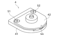
- the perspective view which shows an example of the tilt mechanism.
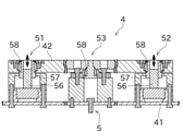
- Sectional drawing which shows an example of a tilt mechanism.
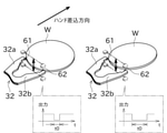
- Explanatory drawing which shows the change of the detected thickness by the inclination of a substrate.
- FIG. 1 is a perspective view showing the overall configuration of the robot 100 according to the embodiment of the present disclosure.
- the robot 100 shown in FIG. 1 is installed in, for example, a manufacturing factory or a warehouse of a substrate W such as a semiconductor wafer or a printed circuit board.
- the robot 100 is used to transfer the substrate W between the substrate processing apparatus and the substrate storage apparatus 7 described later.
- the robot 100 may be used, for example, to transfer the substrate W between a plurality of substrate processing devices that process the substrate W.
- the substrate W may be any of the raw material of the substrate, the semi-finished product being processed, and the processed finished product.
- the shape of the substrate W is a disk shape in the present embodiment, but the shape is not limited to this.
- the robot 100 mainly includes a base 1, a robot arm (arm unit) 2, a robot hand (hand unit) 3, and a robot control unit (board posture inspection unit) 9.
- Base 1 is fixed to the floor of the factory.
- the present invention is not limited to this, and the base 1 may be fixed to, for example, the casing of the substrate processing equipment provided with the above-mentioned substrate processing apparatus. Further, the base 1 may be fixed to a traveling carriage or the like shown in the drawing that runs between the board processing device (or equipment) and the board storage device 7.
- the robot arm 2 is attached to the base 1 via an elevating shaft 11 that can move in the vertical direction.
- the robot arm 2 is rotatable with respect to the elevating shaft 11.
- the robot arm 2 is composed of a horizontal articulated robot arm.
- the robot arm 2 includes a first arm 21 and a second arm 22.
- the first arm 21 is configured as an elongated member extending in a horizontal straight line. One end of the first arm 21 in the longitudinal direction is attached to the upper end of the elevating shaft 11. The first arm 21 is rotatably supported around the axis (vertical axis) of the elevating shaft 11. A second arm 22 is attached to the other end of the first arm 21 in the longitudinal direction.
- the second arm 22 is configured as an elongated member extending in a horizontal straight line. One end in the longitudinal direction of the second arm 22 is attached to the tip of the first arm 21.
- the second arm 22 is rotatably supported around an axis (vertical axis) parallel to the elevating shaft 11.
- a robot hand 3 is attached to the other end of the second arm 22 in the longitudinal direction.
- Each of the elevating shaft 11, the first arm 21, and the second arm 22 is driven by an appropriate actuator (not shown).
- This actuator can be, for example, an electric motor.
- the first arm 21 is located at the arm joint located between the elevating shaft 11 and the first arm 21, between the first arm 21 and the second arm 22, and between the second arm 22 and the robot hand 3.
- the second arm 22, and the encoder of the figure which detects the rotation position of each of the robot hand 3 are attached. Further, at an appropriate position of the robot 100, an encoder for detecting a change in the position of the first arm 21 in the height direction (that is, the amount of elevation of the elevating shaft 11) is also provided.
- the robot control unit 9 has the elevating shaft 11, the first arm 21, and the elevating shaft 11, based on the position information including the rotation position or the height position of the first arm 21, the second arm 22, or the robot hand 3 detected by each encoder. It controls the operation of the electric motor that drives each of the second arm 22 and the robot hand 3.
- position information detected by the encoder means a combination of position information detected by each encoder, which represents the posture of the robot 100.
- the robot hand 3 includes a wrist portion 31 and a hand main body portion 32.
- the wrist portion 31 is attached to the tip of the second arm 22 via the tilt mechanism 4.
- the wrist portion 31 is rotatably supported around an axis (vertical axis) parallel to the elevating shaft 11.
- the tilt mechanism 4 allows the rotation axis of the wrist portion 31 to be tilted with respect to a straight line parallel to the elevating axis 11.
- the detailed configuration of the tilt mechanism 4 will be described later.
- the wrist portion 31 is rotationally driven by an appropriate actuator (not shown). This actuator can be, for example, an electric motor.
- a hand body portion 32 is connected to the wrist portion 31.
- the wrist portion 31 and the hand body portion 32 may be integrally formed.
- the hand body 32 is a part that acts to hold the substrate W.
- the hand body portion 32 is composed of a plate-shaped member formed in a Y-shape (or U-shape).
- the hand body portion 32 has a shape in which the side opposite to the side connected to the wrist portion 31 (in other words, the tip side) is divided into two forks.
- each of the branched portions may be referred to as a first finger portion 32a and a second finger portion 32b.
- the first finger portion 32a and the second finger portion 32b are formed so as to be symmetrical with each other. As shown in FIGS. 4 and 5, an appropriate distance is formed between the tip portions of the first finger portion 32a and the second finger portion 32b. As a result, the edge portion of the substrate W can be positioned between the tip portions of the first finger portion 32a and the second finger portion 32b without bringing the robot hand 3 into contact with the substrate W.
- a plurality of guide portions 33 for holding the substrate W are provided on each of the tip end side and the base end side of the hand body portion 32 of the present embodiment.
- Each guide portion 33 is made of, for example, rubber or the like.
- the guide portion 33 is provided so as to project upward from the plate-shaped hand main body portion 32. As shown in FIG. 1, for example, one guide portion 33 is provided for each of the first finger portion 32a and the second finger portion 32b, and two guide portions 33 are provided on the base end side of the hand main body portion 32.
- the guide portion 33 comes into contact with the lower surface in the vicinity of the peripheral edge of the substrate W placed on the robot hand 3 to hold the substrate W. By contacting the edge of the substrate W from the outside in the radial direction, the guide portion 33 can regulate the substrate W mounted on the robot hand 3 so as not to be displaced in the horizontal direction.
- the configuration in which the robot hand 3 holds the substrate W is not limited to the above configuration.
- the robot hand 3 may hold the substrate W by, for example, a structure that sucks the upper surface or the lower surface of the substrate W with a negative pressure.
- the substrate W may be held in a non-contact manner.
- the tilt mechanism 4 is attached to the tip end side of the second arm 22 (the side opposite to the side connected to the first arm 21).
- the tilt mechanism 4 includes a lower plate portion 41 and an upper plate portion 42.
- the lower plate portion 41 is fixed to the upper surface of the second arm 22.
- the wrist portion 31 of the robot hand 3 is rotatably supported on the upper plate portion 42.
- a height adjusting mechanism 5 is arranged between the lower plate portion 41 and the upper plate portion 42. The tilt mechanism 4 adjusts the inclination angle and the inclination direction of the upper plate portion 42 with respect to the lower plate portion 41 by using the height adjusting mechanism 5.
- the height adjusting mechanism 5 includes, for example, as shown in FIG. 2, three support portions 51, 52, and 53 provided at different positions between the lower plate portion 41 and the upper plate portion 42.
- the support portions 51, 52, and 53 are drawn side by side in a straight line in FIG. 3 for convenience of explanation, but are actually arranged so as to form a triangle in a plan view as shown in FIG.
- Two of the three support portions 51 and 52 include a male screw 56, a female screw 57, and a spherical bearing 58.
- the screw shaft of the male screw 56 is rotatably supported by the lower plate portion 41 with its axis oriented in the vertical direction.
- the screw shaft can be independently rotated by the two support portions 51 and 52 by an actuator (for example, an electric motor) shown in the figure.
- the female screw 57 is screwed to the screw shaft of the male screw 56. When the screw shaft is rotated, the female screw 57 moves in the vertical direction. By this screw feed, the height at which the support portions 51 and 52 support the upper plate portion 42 can be changed.
- a spherical bearing 58 is arranged between the female screw 57 and the upper plate portion 42.
- a spherical bearing 58 is arranged on the remaining support portion 53.
- the support portion 53 does not have a support height changing function by screw feed.
- the inclination angle and the inclination direction of the upper plate portion 42 with respect to the lower plate portion 41 can be changed.
- the posture (inclination angle and inclination direction) of the robot hand 3 with respect to the second arm 22 can be adjusted.
- the height adjusting mechanism 5 (and thus the tilt mechanism 4) is not limited to this configuration.
- the robot control unit 9 stores the detection result of the encoder corresponding to the posture of the robot hand 3 as the posture information of the robot hand 3. As a result, the robot control unit 9 sets each part of the robot 100 (elevating shaft 11, first arm 21, By controlling the electric motor that drives the second arm 22, the robot hand 3, etc.), the posture of the robot hand 3 can be reproduced.
- a mapping sensor (board detection unit) 6 is provided on the tip end side of the hand body unit 32.
- the mapping sensor 6 enables non-contact confirmation (mapping) of the presence or absence of the substrate W.
- the mapping sensor 6 is composed of, for example, a transmissive sensor having a light emitting unit 61 and a light receiving unit 62.
- the mapping sensor 6 is not limited to this, and may be composed of, for example, a reflection type sensor.
- the light projecting portion 61 is provided on the tip end side of the first finger portion 32a.
- the light receiving portion 62 is provided on the tip end side of the second finger portion 32b.
- the light projecting unit 61 irradiates the detection light toward the light receiving unit 62.
- the detection light may be, for example, infrared light, but the detection light is not limited to this.
- the light receiving unit 62 is connected to the robot control unit 9 wirelessly or by wire.
- the light receiving unit 62 outputs an electric signal indicating whether or not the detection light is received to the robot control unit 9.
- the detected light from the light emitting unit 61 reaches the light receiving unit 62, so that the light receiving unit 62 outputs an electric signal with light receiving. do.
- the detected light from the light emitting unit 61 is blocked by the substrate W, so that the light receiving unit 62 outputs an electric signal without light reception.
- the robot control unit 9 brings the tip of the robot hand 3 close to the place where the boards W are arranged.
- the robot hand 3 is moved in the vertical direction across a plurality of placement locations (mapping operation).
- the position of the robot hand 3 in the plan view is such that if the substrate W is tentatively located at the above-mentioned arrangement location, the robot hand 3 does not come into contact with the substrate W and the substrate W is detected by the mapping sensor 6. It is in a position where it can be done. Based on the time-series data of the output of the mapping sensor 6 when the robot hand 3 is moved in the vertical direction, the presence or absence of the substrate W at each arrangement location can be obtained.
- the present invention is not limited to this, and for example, when the robot hand 3 is moved in the vertical direction, the substrate W in each position information detected by the encoder based on the output of the mapping sensor 6 at each position of the robot hand 3 You can also get the presence or absence. That is, the presence / absence information of the substrate W obtained by the output of the mapping sensor 6 is associated with the position information detected by the encoder.
- the place where the light emitting unit 61 and the light receiving unit 62 are arranged in the robot hand 3 is arbitrary.
- the light projecting unit 61 may be built in the first finger part 32a
- the light receiving part 62 may be built in the second finger part 32b.
- the robot control unit 9 is provided separately from the base 1. However, the robot control unit 9 may be arranged inside the base 1.
- the robot control unit 9 is configured as a known computer, and includes an arithmetic processing unit such as a microcontroller, CPU, MPU, PLC, DSP, ASIC, or FPGA, a storage unit such as ROM, RAM, and HDD, and an external device. It is equipped with a communication unit capable of communication.
- the storage unit stores programs executed by the arithmetic processing unit, various setting threshold values, shape data such as the thickness and size of the substrate W to be transported.
- the communication unit is configured to be able to transmit the detection results of various sensors (for example, mapping sensor 6, encoder, etc.) to an external device, and to receive information about the substrate W from the external device.
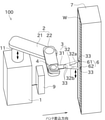
- the substrate storage device 7 shown in FIG. 4 is used for storing the substrate W.
- a plurality of boards (for example, 100 or more) are stored in the board storage device 7 in a state of being arranged at equal intervals in the vertical direction (height direction of the board storage device 7).
- the board W is usually stored in a horizontal posture.
- the substrate W may be stored in the substrate storage device 7 in a non-horizontal posture for some reason such as deformation of the shelf or the presence of foreign matter.
- the robot 100 of the present embodiment can inspect the posture (horizontal plane or inclination with respect to the robot hand 3) of the substrate W before taking out the substrate W from the substrate storage device 7 and transporting the substrate W.
- the inclination of the substrate W can occur three-dimensionally, but in the present embodiment, the substrate W is horizontally tilted along the direction in which the robot hand 3 is inserted into the substrate storage device 7 (hereinafter referred to as the hand insertion direction).
- the inclination of the substrate W from the horizontal can be inspected.
- the object of inspection is the inclination of the substrate W in the roll direction with respect to the hand insertion direction.
- the robot control unit 9 while the hand body unit 32 of the robot hand 3 is kept horizontal, as shown in FIG. 4, a part of the substrate W to be inspected is the first finger portion 32a and the first finger portion 32a. Move it so that it is located between the second finger portions 32b. At this time, the detection light of the mapping sensor 6 is directed so as to be parallel to the proper posture of the substrate W.
- the robot control unit 9 moves the robot hand 3 in the vertical direction while maintaining a horizontal posture by moving the elevating shaft 11 in the vertical direction.
- the mapping sensor 6 scans in the vertical direction.
- the robot hand 3 moves from the lower side to the upper side or from the upper side to the lower side of the substrate W to be inspected. If the moving speed of the robot hand 3 at this time is constant, it is preferable in that the detected thickness TH1 described later can be easily calculated.
- the output signal of the light receiving unit 62 changes, for example, as shown in the graph of FIG.
- the robot control unit 9 analyzes the time-series data based on the output from the light receiving unit 62, so that the light rays from the light projecting unit 61 are blocked by the substrate W to be inspected while the robot hand 3 is moved up and down.
- the cutoff time t0 is obtained. This cutoff time t0 can be rephrased as the detection time when the substrate W is detected by the mapping sensor 6.
- the robot control unit 9 calculates the distance that the robot hand 3 has moved in the vertical direction in the obtained cutoff time t0 as the detection thickness TH1 of the substrate W to be inspected.
- the detected thickness TH1 is the difference between the maximum value and the minimum value of the height (height information) at which the substrate W is detected.
- the distance that blocks the light beam from the light projecting unit 61 is only the actual thickness TH of the substrate W.
- the distance for blocking the light rays from the light projecting portion 61 is larger than the actual thickness TH of the substrate W.
- the robot control unit 9 compares the detected thickness TH1 of the substrate W calculated as described above with the actual thickness TH of the substrate W stored by the storage unit, and thereby the substrate to be inspected. It is determined whether or not W is inclined.
- the actual thickness TH of the substrate W may be calculated in advance based on the design data, manufacturing data, etc. of the substrate W, or the average thickness obtained by measuring the thickness of a plurality of substrates W may be used. good.
- the robot control unit 9 receives the actual thickness TH obtained as described above from the external device in advance via the communication unit and stores it in the storage unit.
- the robot control unit 9 When it is determined that the substrate W is tilted, the robot control unit 9 performs appropriate control. As an example of control, it is conceivable to exclude the substrate W from the target of transportation or stop the operation. As a result, the robot hand 3 does not enter the substrate W in an improper posture, so that damage to the substrate W due to contact between the substrate W and the robot hand 3 can be prevented.
- the posture of the plurality of boards W may be inspected by one vertical movement of the robot hand 3.
- the cycle time can be shortened by acquiring the time-series data of the mapping sensor 6 for checking the presence or absence of the board W and inspecting the posture of the board W by one vertical movement of the robot hand 3. Preferred in terms of points.
- the robot 100 of the present embodiment is used to convey the substrate W.
- the robot 100 includes a robot arm 2, a robot hand 3, a mapping sensor 6, and a robot control unit 9.
- the robot hand 3 is provided on the robot arm 2 and holds and conveys the substrate W.
- the mapping sensor 6 detects the presence / absence of the substrate W in a non-contact manner.
- the robot control unit 9 inspects the posture of the substrate W based on the height detected by the mapping sensor 6 for the substrate W in a state where it is not held by the robot hand 3.
- the mapping sensor 6 is provided on the robot hand 3.
- the robot control unit 9 obtains the maximum value and the minimum value of the detected height of the substrate W based on the output from the mapping sensor 6 when the robot hand 3 is moved in the vertical direction.
- the robot control unit 9 inspects the posture of the substrate W based on the detected thickness TH1 which is the difference between the upper limit value and the lower limit value and the actual thickness TH which is the actual thickness of the substrate W.
- the robot 100 of the present embodiment includes a tilt mechanism 4 capable of tilting the posture of the robot hand 3 in an arbitrary direction.
- the orientation of the mapping sensor 6, which is the reference for the posture inspection of the substrate W, can be adjusted with a high degree of freedom.
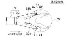
- FIG. 7 is a plan view illustrating an inclination inspection of the substrate W in the first modification.
- the same reference numerals may be given to the drawings for the same or similar members as those in the above-described embodiment, and the description may be omitted.
- the robot 100 of this modification is equipped with a range finder 6x in addition to the mapping sensor 6.
- the rangefinder 6x, together with the mapping sensor 6, constitutes a substrate detection unit.
- the rangefinder 6x can detect the inclination of the substrate W from the horizontal when the substrate W is viewed horizontally in the direction perpendicular to the above-mentioned hand insertion direction.
- the object of inspection by the rangefinder 6x is the inclination of the substrate W in the pitch direction with respect to the hand insertion direction.
- the detection result of the rangefinder 6x corresponds to the height information.
- the distance meter 6x is composed of, for example, a laser displacement meter, an ultrasonic distance sensor, and the like. As shown in FIG. 7, for example, the range finder 6x is provided on the upper surface of the second finger portion 32b of the hand main body portion 32. The range finder 6x detects the vertical distance from the range finder 6x to the lower surface of the substrate W in a non-contact manner. The range finder 6x is wirelessly or wiredly connected to the robot control unit 9, and transmits the distance to the substrate W measured at the measurement position to the robot control unit 9.
- the robot control unit 9 inserts the robot hand 3 below the board W supported by the board storage device 7. As a result, the substrate W faces the rangefinder 6x in the vertical direction. However, in this state, the substrate W is not held by the guide portion 33.
- the robot control unit 9 measures the distance from the distance meter 6x to the substrate W to be inspected at at least two points by moving the robot hand 3 horizontally along the hand insertion direction in this state.
- the robot control unit 9 determines whether or not the substrate W is tilted with respect to the horizontal direction based on the difference in height of the substrate W measured by the distance meter 6x at two points of the substrate W.
- the rangefinder 6x measures a value that cannot normally be taken. Therefore, it can be said that the rangefinder 6x is a sensor that can substantially detect the presence or absence of the substrate W.
- the mapping sensor 6 can inspect the inclination of the substrate W in the roll direction when viewed along the hand insertion direction.
- the inclination in the pitch direction can be inspected by the rangefinder 6x. Therefore, in this modification, the inclination of the substrate W can be inspected three-dimensionally.
- the distance meter 6x is provided on the hand body 32 in order to measure the distance from the substrate W in the vertical direction.
- the robot control unit 9 inspects the posture of the substrate W based on each of the distances measured by the distance meter 6x at a plurality of locations on the substrate W.
- FIG. 8 is a plan view conceptually showing the inclination inspection of the substrate W in the second modification.
- the same reference numerals may be given to the drawings for the same or similar members as those in the above-described embodiment, and the description may be omitted.
- the robot 100 of this modification includes only the mapping sensor 6 as the board detection unit. In other words, the robot 100 does not have a rangefinder 6x.
- the robot 100 of this modification performs the same measurement as the above-described embodiment while changing the direction of the detection light of the mapping sensor 6 in a plan view, and obtains the detection thickness TH1. do.
- the inclination can be determined by comparing the detected thickness TH1 with the actual thickness TH in the same manner as described above.
- the direction of the detection light is not limited to the example shown in FIG. 8, and can be changed in various ways.
- the inclination of the substrate W can be inspected three-dimensionally by using the two detection thicknesses TH1.
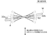
- FIG. 9 is a diagram conceptually explaining how the direction of the detection axis of the mapping sensor 6 is changed in order to detect the inclination of the substrate W in the third modification.
- the same reference numerals may be given to the drawings for the same or similar members as those in the above-described embodiment, and the description may be omitted.
- the robot control unit 9 obtains the detection thickness TH1 a plurality of times by appropriately changing the direction and size of the detection light of the mapping sensor 6. Specifically, the robot control unit 9 tilts the direction of the detection light of the mapping sensor 6 in the roll direction by appropriately tilting the robot hand 3 from the horizontal. After that, the robot control unit 9 moves the robot hand 3 in the vertical direction to obtain the detected thickness TH1 in a state where the robot hand 3 is tilted.
- the robot control unit 9 obtains the inclination angle of the detected light when the difference between the detected thickness TH1 and the actual thickness TH is the smallest.
- This tilt angle means the tilt angle ⁇ of the substrate W in the roll direction.
- This inclination angle ⁇ can be used as an index showing how much the substrate W deviates from the correct posture.
- the robot control unit 9 performs an inspection while changing the posture of the robot hand 3 by using the tilt mechanism 4, so that the magnitude of the inclination of the substrate W can be determined.
- the indicated tilt angle ⁇ is acquired.
- the detection thickness TH1 is obtained at the time when the mapping sensor 6 starts the output without light reception and instead of obtaining it based on the distance moved in the vertical direction while the mapping sensor 6 outputs no light reception. It may be obtained based on the detection result (position information detected by the encoder) of the encoder at the time when the output of none is finished. In this case, the position information detected by the encoder corresponds to the height information.
- the position change of the first arm 21 in the height direction is used to calculate the detection thickness TH1. Only the detection result of the encoder that detects (the amount of elevation of the elevating shaft 11) can be used.
- the robot 100 may indirectly convey the substrate W by holding a tray or the like for accommodating the substrate W, instead of directly holding and transporting the substrate W.
- the hand body portion 32 of the robot hand 3 may be integrally formed with the upper plate portion 42 of the tilt mechanism 4.
- the tilt mechanism 4 may be arranged between the base 1 and the elevating shaft 11, may be arranged between the elevating shaft 11 and the first arm 21, or may be arranged between the first arm 21 and the second arm 22. It may be placed in between.
- the substrate W is tilted by somehow specifying the position of the light emitting portion 61 and the light receiving portion 62 of the mapping sensor 6 with respect to the substrate W in a plan view. It is also possible to calculate the angle ⁇ . This calculation can be easily performed by performing a geometric calculation based on the detected thickness TH1. The same applies to the modified examples shown in FIGS. 7 and 8.
- the mapping sensor 6 can be omitted. Even in this case, the inclination of the substrate W in the pitch direction can be inspected by horizontally scanning the rangefinder 6x along the hand insertion direction. Further, while the robot hand 3 is appropriately moved in the horizontal plane, the heights of the three points having a triangular shape in a plan view on the substrate W may be measured by the range finder 6x. In this case, the inclination of the substrate W can be inspected three-dimensionally only with the distance meter 6x.
- a plurality of rangefinders 6x may be arranged in different places from each other.
- the above-mentioned inspection of the inclination of the substrate W may be performed by an inspection device separately provided instead of the robot control unit 9.
- the functions of the elements disclosed herein include general purpose processors, dedicated processors, integrated circuits, ASICs (Application Specific Integrated Circuits), conventional circuits, and / or, which are configured or programmed to perform the disclosed functions. It can be performed using a circuit or processing circuit that includes a combination thereof.
- a processor is considered a processing circuit or circuit because it includes transistors and other circuits.
- a circuit, unit, or means is hardware that performs the listed functions, or hardware that is programmed to perform the listed functions.
- the hardware may be the hardware disclosed herein, or it may be other known hardware that is programmed or configured to perform the listed functions. If the hardware is a processor considered to be a type of circuit, the circuit, means, or unit is a combination of hardware and software, and the software is used to configure the hardware and / or processor.
Landscapes
- Engineering & Computer Science (AREA)
- Robotics (AREA)
- Mechanical Engineering (AREA)
- Human Computer Interaction (AREA)
- Health & Medical Sciences (AREA)
- General Health & Medical Sciences (AREA)
- Orthopedic Medicine & Surgery (AREA)
- Manipulator (AREA)
- Container, Conveyance, Adherence, Positioning, Of Wafer (AREA)
- Investigating Materials By The Use Of Optical Means Adapted For Particular Applications (AREA)
Abstract
Description
Claims (6)
- 基板を搬送するためのロボットであって、
アーム部と、
前記アーム部に設けられ、前記基板を保持して搬送するハンド部と、
前記基板の有無を非接触で検出する基板検出部と、
前記ハンド部によって保持されていない状態の前記基板が前記基板検出部により検出された高さ情報に基づいて、前記基板の姿勢を検査する基板姿勢検査部と、
を備えることを特徴とするロボット。 - 請求項1に記載のロボットであって、
前記基板検出部は、前記ハンド部に設けられたマッピングセンサを備え、
前記基板姿勢検査部は、
前記ハンド部を上下方向に移動させたときの前記マッピングセンサからの出力に基づいて、前記基板が検出された高さの最大値と最小値を求め、
前記最大値と前記最小値の差である検出厚みと、前記基板の実際の厚みである実厚みと、に基づいて、前記基板の姿勢を検査することを特徴とするロボット。 - 請求項1又は2に記載のロボットであって、
前記基板検出部は、上下方向での前記基板との距離を測定するために前記ハンド部に設けられた距離計を備え、
前記基板姿勢検査部は、前記基板の複数箇所において前記距離計により測定された前記距離のそれぞれに基づいて、前記基板の姿勢を検査することを特徴とするロボット。 - 請求項1から3までの何れか一項に記載のロボットであって、
前記ハンド部の姿勢を任意の方向に傾けることが可能なチルト機構を備えることを特徴とするロボット。 - 請求項4に記載のロボットであって、
前記基板姿勢検査部は、前記チルト機構を用いて前記ハンド部の姿勢を変更しながら検査を行うことにより、前記基板の傾斜の大きさを取得することを特徴とするロボット。 - アーム部と、
前記アーム部に設けられ、基板を保持して搬送するハンド部と、
前記基板の有無を非接触で検出する基板検出部と、
を備え、前記基板を搬送するロボットによって、当該基板の姿勢を検査する基板姿勢検査方法であって、
前記基板検出部が検出した、前記ハンド部によって保持されていない状態の前記基板の高さ情報に基づいて、前記基板の姿勢を検査することを特徴とする基板姿勢検査方法。
Priority Applications (3)
| Application Number | Priority Date | Filing Date | Title |
|---|---|---|---|
| US18/024,508 US12485534B2 (en) | 2020-09-04 | 2021-08-29 | Robot and substrate orientation examination method |
| CN202180054635.8A CN116349001B (zh) | 2020-09-04 | 2021-08-29 | 机器人以及基板姿势检查方法 |
| KR1020237003966A KR102785301B1 (ko) | 2020-09-04 | 2021-08-29 | 로봇 및 기판 자세 검사 방법 |
Applications Claiming Priority (2)
| Application Number | Priority Date | Filing Date | Title |
|---|---|---|---|
| JP2020148882A JP7614763B2 (ja) | 2020-09-04 | 2020-09-04 | ロボット及び基板姿勢検査方法 |
| JP2020-148882 | 2020-09-04 |
Publications (1)
| Publication Number | Publication Date |
|---|---|
| WO2022050201A1 true WO2022050201A1 (ja) | 2022-03-10 |
Family
ID=80491750
Family Applications (1)
| Application Number | Title | Priority Date | Filing Date |
|---|---|---|---|
| PCT/JP2021/031627 Ceased WO2022050201A1 (ja) | 2020-09-04 | 2021-08-29 | ロボット及び基板姿勢検査方法 |
Country Status (5)
| Country | Link |
|---|---|
| US (1) | US12485534B2 (ja) |
| JP (1) | JP7614763B2 (ja) |
| KR (1) | KR102785301B1 (ja) |
| TW (1) | TWI780890B (ja) |
| WO (1) | WO2022050201A1 (ja) |
Families Citing this family (3)
| Publication number | Priority date | Publication date | Assignee | Title |
|---|---|---|---|---|
| JP2024080228A (ja) * | 2022-12-02 | 2024-06-13 | 株式会社安川電機 | 基板搬送装置および基板搬送方法 |
| US12172429B2 (en) * | 2023-02-02 | 2024-12-24 | Agilent Technologies, Inc. | Substrate orientation device for liquid dispensing operations |
| KR102831742B1 (ko) * | 2023-05-10 | 2025-07-10 | 한국전력공사 | 전력구 점검장치 및 이를 이용한 점검방법 |
Citations (3)
| Publication number | Priority date | Publication date | Assignee | Title |
|---|---|---|---|---|
| JPH07153818A (ja) * | 1993-11-30 | 1995-06-16 | Daihen Corp | 半導体ウエハ認識装置 |
| JP2019149478A (ja) * | 2018-02-27 | 2019-09-05 | オムロン株式会社 | センサシステム、および、傾き検出方法 |
| JP2020053416A (ja) * | 2018-09-21 | 2020-04-02 | オムロン株式会社 | センサシステム、および、傾き検出方法 |
Family Cites Families (8)
| Publication number | Priority date | Publication date | Assignee | Title |
|---|---|---|---|---|
| JP4509411B2 (ja) * | 2001-03-26 | 2010-07-21 | 株式会社ディスコ | 搬出入装置 |
| JP2004128021A (ja) | 2002-09-30 | 2004-04-22 | Mitsubishi Electric Corp | ウェハ搬送装置 |
| US6813543B2 (en) * | 2002-10-08 | 2004-11-02 | Brooks-Pri Automation, Inc. | Substrate handling system for aligning and orienting substrates during a transfer operation |
| DE102009016811A1 (de) * | 2009-04-09 | 2010-10-14 | Aes Motomation Gmbh | Verfahren zur automatischen Vermessung und zum Einlernen von Lagepositionen von Objekten innerhalb eines Substratprozessiersystems mittels Sensorträger und zugehöriger Sensorträger |
| EP2891174B1 (en) | 2012-08-31 | 2019-08-14 | Semiconductor Technologies & Instruments Pte Ltd. | System and method for automatically correcting for rotational misalignment of wafers on film frames |
| JP6522325B2 (ja) * | 2014-12-08 | 2019-05-29 | 日本電産サンキョー株式会社 | 産業用ロボットおよび産業用ロボットの教示方法 |
| JP7614764B2 (ja) * | 2020-09-04 | 2025-01-16 | 川崎重工業株式会社 | ロボット及び基板形状異常検査方法 |
| JP7671574B2 (ja) * | 2020-10-02 | 2025-05-02 | ニデックインスツルメンツ株式会社 | 産業用ロボット |
-
2020
- 2020-09-04 JP JP2020148882A patent/JP7614763B2/ja active Active
-
2021
- 2021-08-29 KR KR1020237003966A patent/KR102785301B1/ko active Active
- 2021-08-29 WO PCT/JP2021/031627 patent/WO2022050201A1/ja not_active Ceased
- 2021-08-29 US US18/024,508 patent/US12485534B2/en active Active
- 2021-09-03 TW TW110132738A patent/TWI780890B/zh active
Patent Citations (3)
| Publication number | Priority date | Publication date | Assignee | Title |
|---|---|---|---|---|
| JPH07153818A (ja) * | 1993-11-30 | 1995-06-16 | Daihen Corp | 半導体ウエハ認識装置 |
| JP2019149478A (ja) * | 2018-02-27 | 2019-09-05 | オムロン株式会社 | センサシステム、および、傾き検出方法 |
| JP2020053416A (ja) * | 2018-09-21 | 2020-04-02 | オムロン株式会社 | センサシステム、および、傾き検出方法 |
Also Published As
| Publication number | Publication date |
|---|---|
| JP2022043554A (ja) | 2022-03-16 |
| KR20230031953A (ko) | 2023-03-07 |
| US12485534B2 (en) | 2025-12-02 |
| US20240025037A1 (en) | 2024-01-25 |
| TW202220810A (zh) | 2022-06-01 |
| KR102785301B1 (ko) | 2025-03-25 |
| JP7614763B2 (ja) | 2025-01-16 |
| CN116349001A (zh) | 2023-06-27 |
| TWI780890B (zh) | 2022-10-11 |
Similar Documents
| Publication | Publication Date | Title |
|---|---|---|
| JP7614764B2 (ja) | ロボット及び基板形状異常検査方法 | |
| JP7610939B2 (ja) | ロボット及びハンド部姿勢調整方法 | |
| US12371279B2 (en) | Robot and hand orientation adjustment method | |
| TWI676232B (zh) | 基板搬送機構之位置檢測方法、記憶媒體及基板搬送機構之位置檢測裝置 | |
| TWI593526B (zh) | Robot teaching methods and robots | |
| TWI780890B (zh) | 機器人以及基板姿勢檢查方法 | |
| KR102374083B1 (ko) | 기판 반송 로봇 및 기판 유지 핸드의 광축 어긋남 검출 방법 | |
| JP5544414B2 (ja) | センサキャリアにより基板処理システム内の物体の位置を自動的に測定して教示する方法および関連するセンサキャリア | |
| TWI675431B (zh) | 基板搬送裝置及求出基板搬送機器人與基板載置部之位置關係之方法 | |
| TW201546588A (zh) | 教導單元及教導方法 | |
| US7596425B2 (en) | Substrate detecting apparatus and method, substrate transporting apparatus and method, and substrate processing apparatus and method | |
| TW201703181A (zh) | 基板檢出裝置、基板檢出方法及基板處理系統 | |
| CN115910846A (zh) | 示教设备和使用该示教设备的基板对准设备 | |
| TW202123360A (zh) | 用於生產和製程控制工具之基板搬運之自動教導 | |
| CN118204965A (zh) | 原点校准方法及原点校准系统 | |
| CN118205012A (zh) | 机器人检查系统 | |
| JP2021053718A (ja) | ワークを検出する検出システム | |
| JP2025164396A (ja) | 基板搬送ロボットおよび基板搬送ロボットの制御方法 | |
| KR20250018092A (ko) | 반송 교시 방법, 및 기판 처리 시스템 |
Legal Events
| Date | Code | Title | Description |
|---|---|---|---|
| 121 | Ep: the epo has been informed by wipo that ep was designated in this application |
Ref document number: 21864259 Country of ref document: EP Kind code of ref document: A1 |
|
| ENP | Entry into the national phase |
Ref document number: 20237003966 Country of ref document: KR Kind code of ref document: A |
|
| WWE | Wipo information: entry into national phase |
Ref document number: 18024508 Country of ref document: US |
|
| NENP | Non-entry into the national phase |
Ref country code: DE |
|
| 122 | Ep: pct application non-entry in european phase |
Ref document number: 21864259 Country of ref document: EP Kind code of ref document: A1 |