WO2022050002A1 - 呼吸音情報処理システム及び呼吸音測定装置 - Google Patents
呼吸音情報処理システム及び呼吸音測定装置 Download PDFInfo
- Publication number
- WO2022050002A1 WO2022050002A1 PCT/JP2021/029446 JP2021029446W WO2022050002A1 WO 2022050002 A1 WO2022050002 A1 WO 2022050002A1 JP 2021029446 W JP2021029446 W JP 2021029446W WO 2022050002 A1 WO2022050002 A1 WO 2022050002A1
- Authority
- WO
- WIPO (PCT)
- Prior art keywords
- measurement data
- measuring device
- sound
- breath
- processing system
- Prior art date
- Legal status (The legal status is an assumption and is not a legal conclusion. Google has not performed a legal analysis and makes no representation as to the accuracy of the status listed.)
- Ceased
Links
Images

Classifications
-
- A—HUMAN NECESSITIES
- A61—MEDICAL OR VETERINARY SCIENCE; HYGIENE
- A61B—DIAGNOSIS; SURGERY; IDENTIFICATION
- A61B5/00—Measuring for diagnostic purposes; Identification of persons
- A61B5/08—Measuring devices for evaluating the respiratory organs
-
- A—HUMAN NECESSITIES
- A61—MEDICAL OR VETERINARY SCIENCE; HYGIENE
- A61B—DIAGNOSIS; SURGERY; IDENTIFICATION
- A61B7/00—Instruments for auscultation
- A61B7/02—Stethoscopes
- A61B7/04—Electric stethoscopes
Definitions
- the present invention relates to a respiratory sound information processing system and a respiratory sound measuring device.
- Patent Document 1 includes a device that detects a breath sound of a person to be measured, acquires a time-series breath sound signal representing the breath sound, and displays a time transition of the frequency of wheezing of the person to be measured. It has been disclosed.
- the wheezing sensor can determine the presence or absence of wheezing, it cannot comprehensively determine the asthma status. Therefore, the user may not be motivated to continuously measure wheezing only with the information on the presence or absence of wheezing obtained by the conventional wheezing sensor.
- the present invention has been made in view of such circumstances on one aspect, and an object thereof is to provide a technique capable of providing a user with more useful information based on a measurement result.
- the present invention adopts the following configuration in order to solve the above problems.
- the breathing sound information processing system notifies the user of the detection result of asthma based on the measurement data obtained by measuring the breathing sound of the person to be measured, and transmits the measurement data. It includes a breathing sound measuring device and a server that performs analysis based on the measurement data transmitted by the breathing sound measuring device and transmits the analysis result to the user's information terminal.
- the server not the breath sound measuring device, performs analysis based on the measurement data obtained by the breath sound measuring device, and provides the user with more useful analysis results as well as the presence or absence of wheezing at the time of measurement. be able to.
- the user provides the analysis result to the doctor, more appropriate medical treatment becomes possible.
- the server may transmit the analysis result based on the plurality of measurement data transmitted by the breath sound measuring device to the user's information terminal. According to this configuration, the user can obtain highly accurate analysis results as the measurement is performed, so that the user's motivation for continuous measurement can be improved.
- the server when the number of times the measurement data is transmitted by the breathing sound measuring device satisfies a predetermined condition, the server obtains the analysis result based on the plurality of measurement data. It may be sent to the terminal. According to this configuration, the user cannot obtain the analysis result unless the number of transmissions of the measurement data satisfies a predetermined condition, so that the user's motivation for continuous measurement can be improved.
- the server obtains the analysis result based on the plurality of measurement data when the transmission frequency of the measurement data by the breathing sound measuring device satisfies a predetermined condition. It may be sent to the terminal. According to this configuration, the user can improve the motivation of the user for continuous measurement because the analysis result cannot be obtained unless the transmission frequency of the measurement data satisfies a predetermined condition.
- the breath sound measuring device may transmit the measurement data via the information terminal of the user.
- the measurement data can be transmitted to the server via the information terminal even if the breath sound measuring device itself does not have a configuration for communicating with the server.
- the server may transmit the analysis result to the information terminal when the analysis result satisfies a predetermined condition. According to this configuration, it is possible to provide the analysis result to the user when an analysis result important to the user is obtained or an analysis result different from the past analysis result is obtained.
- the breathing sound measuring device is a sound measuring unit for measuring the breathing sound of the person to be measured, and a user who detects asthma based on the measurement data obtained by the measurement of the sound measuring unit.
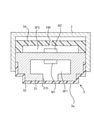
- FIG. 3 is a schematic cross-sectional view taken along the line AA in the respiratory sound measuring device 1 shown in FIG.
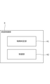
- FIG. 3 shows an example of the structure of the integrated control unit 4.
- FIG. 3 shows an example of the hardware composition of an information terminal 12.
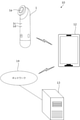
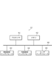
- FIG. 1 is a diagram showing a configuration of a breath sound information processing system 10 which is an example of an embodiment.
- the breath sound information processing system 10 includes a breath sound measuring device 1, an information terminal 12, and a server 13.
- the respiratory sound measuring device 1 measures the respiratory sound of the person to be measured by pressing the head portion 1a against the body surface (skin) of the person to be measured. Since the breath sounds of a person suffering from asthma include wheezing, the condition of asthma and the like of the person to be measured can be known from the breath sounds measured by the breath sounds measuring device 1.
- the breath sound measuring device 1 obtains measurement data by measuring the breath sound.
- This measurement data is, for example, data showing a waveform of a breath sound obtained by measuring the breath sound.
- the measurement data may be data indicating the feature amount (for example, peak value, peak timing and frequency, etc.) of the breath sound waveform obtained by the measurement of the breath sound.
- the measurement data may be data indicating the level of wheezing in three or more stages.
- the breath sound measuring device 1 detects wheezing based on the obtained measurement data and notifies the user of the wheezing detection result.
- the respiratory sound measuring device 1 has a wheezing notification lamp 1c for notifying that wheezing has been detected, and a wheezing non-notifying lamp 1d for notifying that wheezing has not been detected.
- Each of the wheezing notification lamp 1c and the wheezing non-notification lamp 1d is a light source such as an LED (Light Emitting Diode).
- the measurement data is data indicating the level of wheezing in five stages (for example, "1" to "5").
- the respiratory sound measuring device 1 determines that wheezing is present if the wheezing level indicated by the measurement data is equal to or higher than the threshold value (for example, "3"), turns on the wheezing notification lamp 1c, and the wheezing level indicated by the measurement data is set. If it is less than the threshold value, it is determined that there is no wheezing, and the wheezing non-notification lamp 1d is turned on.
- the threshold value for example, "3"
- the breath sound measuring device 1 may notify the wheezing detection result not only by lighting the lamp but also by voice output, screen display, vibration, or the like.
- the respiratory sound measuring device 1 may notify the wheezing detection result from the information terminal 12 by communicating with the information terminal 12.
- the breath sound measuring device 1 can communicate with the information terminal 12.
- the respiratory sound measuring device 1 is capable of wireless communication with the information terminal 12.
- the respiratory sound measuring device 1 communicates with the information terminal 12 to transmit the measurement data obtained by the measurement of the respiratory sound to the server 13.
- the measurement data transmitted by the breath sound measuring device 1 to the server 13 is the measurement data used for detecting the wheezing, and is more detailed (more information) than the wheezing detection result.
- the information terminal 12 is an information terminal possessed by the user of the respiratory sound measuring device 1.
- the information terminal 12 is a smartphone, but the information terminal 12 is not limited to a smartphone, and may be a tablet terminal, a personal computer, or the like.
- the information terminal 12 can communicate with the server 13 via the network 14.
- the network 14 is, for example, WAN (Wide Area Network).
- the communication between the information terminal 12 and the network 14 may be a wired communication such as a wired LAN (Local Area Network) or a wireless communication such as a wireless LAN.
- the information terminal 12 receives measurement data from the respiratory sound measuring device 1 by communicating with the respiratory sound measuring device 1. Then, the information terminal 12 transmits the received measurement data to the server 13 via the network 14.
- the server 13 receives the measurement data transmitted from the breath sound measuring device 1 by communicating with the information terminal 12 via the network 14. Then, the server 13 performs an analysis based on the received measurement data.
- the analysis by the server 13 is an analysis regarding the condition of the subject such as asthma based on the measurement data.
- the analysis by the server 13 can detect signs of wheezing or seizures, analyze the strength and frequency of breathing, determine whether the subject's condition requires hospital visits, and determine the subject's condition. It is a judgment as to whether or not the hospital visit should be continued.
- the analysis by the server 13 may be based on a specific algorithm, or a large number of sets of measurement data of an unspecified subject and information based on the measurement data (for example, a medical examination result) are used. It may be based on learned AI (Artificial Intelligence) or the like.
- the server 13 communicates with the information terminal 12 via the network 14 to transmit the analysis result based on the measurement data to the information terminal 12.
- the information terminal 12 notifies the user of the analysis result received from the server 13 by screen display or voice output.
- the server 13 may be one server device connected to the network 14 or a virtual server realized by one or more server devices connected to the network 14.
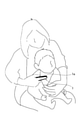
- FIG. 2 is a diagram showing an example of a scene in which the breath sound measuring device 1 is used.
- the user of the breath sounds measuring device 1 (parent in FIG. 1) holds the breath sounds measuring device 1 with one hand as shown in FIG.
- the head portion 1a is pressed against the body surface of the infant) with a finger.
- the head portion 1a may be pressed against the body surface by a finger of a hand other than the hand holding the respiratory sound measuring device 1.
- FIG. 3 is a side view showing an example of a schematic configuration of the breath sound measuring device 1.
- the respiratory sound measuring device 1 has a rod-shaped grip portion 1b made of a housing made of resin or metal, and a head portion 1a is provided on one end side of the grip portion 1b. There is.
- a integrated control unit 4 that controls the entire breath sound measuring device 1, a battery 5 that supplies the voltage required for operation, a wheezing notification lamp 1c, and a wheezing non-notification lamp 1d are driven.
- a wireless communication unit 7 that performs wireless communication between the drive unit 6 and the information terminal 12 is provided. In FIG. 3, the wheezing notification lamp 1c and the wheezing non-notification lamp 1d are not shown.
- the wireless communication unit 7 is a communication interface capable of short-range wireless communication such as Bluetooth (registered trademark).
- the wireless communication unit 7 is an example of a transmission unit of the information terminal 12.
- the wheezing notification lamp 1c, the wheezing non-notification lamp 1d, and the driving unit 6 are examples of the notification unit of the information terminal 12.
- the integrated control unit 4 includes various processors, a RAM (Random Access Memory), a ROM (Read Only Memory), and the like, and controls each hardware of the breath sound measuring device 1 according to a program.
- the ROM for operating the breath sound measuring device 1 is stored in the ROM of the integrated control unit 4.
- programmable logic is a processor whose circuit configuration can be changed after manufacturing such as a general-purpose processor that executes a program and performs various processes, such as a CPU (Central Processing Unit) and an FPGA (Field Programgable Gate Array). It includes a dedicated electric circuit, which is a processor having a circuit configuration specially designed for executing a specific process such as a device (Programmable Logic Device: PLD) or an ASIC (Application Specific Integrated Circuit).
- PLD Programmable Logic Device
- ASIC Application Specific Integrated Circuit
- the structure of these various processors is an electric circuit in which circuit elements such as semiconductor elements are combined.
- the integrated control unit 4 may be configured by one of various processors, or may be configured by a combination of two or more processors of the same type or different types (for example, a combination of a plurality of FPGAs or a combination of a CPU and an FPGA). May be done.
- the head portion 1a is provided with a measurement unit 3 projecting to one side (lower side in FIG. 3) in a direction different from the longitudinal direction of the grip portion 1b.
- a pressure receiving portion 3a that is in contact with the body surface S of the living body to be measured and receives pressure from the body surface S is provided.
- the index finger of the user's hand Ha is placed on the back surface of the measuring unit 3 in the head portion 1a, and the pressure receiving portion 3a of the measuring unit 3 is pressed against the body surface S by the index finger. used.
- FIG. 4 is a schematic cross-sectional view taken along the line AA in the respiratory sound measuring device 1 shown in FIG.
- the measuring unit 3 accommodates the first sound measuring instrument M1 for measuring sound and the first sound measuring instrument M1 in the internal accommodation space SP1 and presses against the body surface S of the living body.
- a bottomed tubular first housing 31 having an opening 31h closed by the body surface S in the closed state, and a housing cover 32 that closes the opening 31h from the outside of the first housing 31 and covers the first housing 31.
- a second sound measuring instrument M2 for measuring sound and a second housing 34 forming an accommodation space SP2 for accommodating the second sound measuring instrument M2 and having an opening 34h are provided.
- the measurement unit 3 is fitted to the opening formed in the housing 2 constituting the head portion 1a in a state where a part of the housing cover 32 is exposed, and is fixed to the housing 2.
- the tip of the exposed portion of the housing cover 32 from the housing 2 is a flat surface or a curved surface, and this flat surface or a curved surface constitutes the pressure receiving portion 3a.
- the housing 2 is made of a resin or the like capable of transmitting sound.
- the first sound measuring device M1 is for measuring a breathing sound, and for example, a band wider than the frequency range of the breathing sound (generally 10 Hz or more and 1 kHz or less) (for example, a frequency range of 10 Hz or more and 10 kHz or less). ) Is composed of a MEMS (Micro Electro Mechanical Systems) type microphone, a capacitance type microphone, or the like for measuring the sound.
- the first sound measuring instrument M1 is an example of a sound measuring unit.
- the first sound measuring device M1 is electrically connected to the integrated control unit 4 shown in FIG. 3 by a lead wire or the like (not shown), and transmits the measured breath sound signal to the integrated control unit 4.
- the pressure receiving portion 3a of the housing cover 32 comes into contact with the body surface S, and the accommodation space SP1 is sealed by the body surface S via the housing cover 32 due to the pressure from the body surface S. It becomes a closed state (hereinafter, this state is referred to as a closed state).
- the pressure receiving portion 3a vibrates due to the breathing sound transmitted from the living body to the body surface S
- the internal pressure of the accommodation space SP1 fluctuates due to this vibration
- the electric signal corresponding to the breathing sound is the first sound measuring device due to the fluctuation of the internal pressure. It will be measured by M1.
- the first housing 31 has a substantially convex shape toward the downward direction in FIG. 4, and is made of a material such as resin or metal, which has higher acoustic impedance and higher rigidity than air.
- the first housing 31 is made of a material that reflects sound in the measurement frequency band of the first sound measuring instrument M1 so that sound is not transmitted from the outside to the inside of the accommodation space SP1 in a closed state.
- the housing cover 32 is a bottomed cylindrical member, and the shape of the hollow portion thereof substantially matches the shape of the outer wall of the first housing 31.
- the housing cover 32 is made of a material having an acoustic impedance close to that of the human body, air, or water, and having flexibility with good biocompatibility.
- a material having an acoustic impedance close to that of the human body, air, or water, and having flexibility with good biocompatibility for example, silicone, elastomer, or the like is used.
- the second sound measuring instrument M2 is for measuring the sound around the first housing 31 (environmental sound such as human voice, or rubbing sound between the device and the living body or clothes).
- it is composed of a MEMS type microphone or a capacitance type microphone that measures a sound in a band wider than the frequency range of the breathing sound (for example, a frequency range of 10 Hz or more and 10 kHz or less).
- the second sound measuring instrument M2 is electrically connected to the integrated control unit 4 shown in FIG. 3 by a lead wire or the like (not shown), and transmits the measured ambient sound signal to the integrated control unit 4.
- the second sound measuring instrument M2 is fixed to the surface of the first housing 31 opposite to the pressure receiving portion 3a side.
- the circumference of the second sound measuring instrument M2 is covered by the second housing 34.
- the second housing 34 is made of a material (for example, resin) so that the sound generated around the breath sound measuring device 1 easily enters the accommodation space SP2 accommodating the second sound measuring device M2.
- An opening 34h is formed in the second housing 34. Therefore, the structure is such that the sound generated around the breath sound measuring device 1 can easily enter through the opening 34h.
- FIG. 5 is a diagram showing an example of the configuration of the integrated control unit 4.
- the processor of the integrated control unit 4 operates as the wheezing determination unit 41 and the control unit 42 by executing the wheezing detection program.
- the wheezing determination unit 41 is an operation member (not shown) for instructing the start of the wheezing detection process provided on the grip portion 1b, for example, in a state where the pressure receiving portion 3a is in contact with the body surface S of the person to be measured. Is operated to give an instruction to start the wheezing detection process, the breath sound signal measured by the first sound measuring device M1 and the ambient sound signal measured by the second sound measuring device M2. , Are sequentially acquired.
- the timing at which the sound is first measured by the first sound measuring instrument M1 and the second sound measuring instrument M2 after the above start instruction is given is referred to as a measurement start time point.
- the wheezing determination unit 41 determines whether or not the breath sounds of the subject include wheezing, that is, wheezing, based on the respiratory sound signal and the ambient sound signal (measurement data) sequentially acquired after the start instruction is given. Performs a process for determining the presence or absence of wheezing (hereinafter referred to as a wheezing determination process).
- the wheezing determination unit 41 for example, when the respiratory sound signal and the ambient sound signal (referred to as the processing target signal group) for a predetermined processing time (for example, 1 second, etc.) are accumulated, the processing target signal group The presence or absence of wheezing is determined based on.
- the wheezing determination unit 41 for example, removes noise other than the breath sounds mixed in the breath sounds signal included in the processing target signal group based on the ambient sound signal. Then, the wheezing determination unit 41 determines the presence or absence of wheezing based on the signal of the breath sound after the noise is removed.
- the method for determining the presence or absence of wheezing based on the breath sound signal is not particularly limited, but for example, the method described in Patent Document 1 may be adopted.
- the wheezing determination unit 41 performs such processing each time a new processing target signal group is accumulated, and determines the presence or absence of wheezing for each processing time.
- the control unit 42 determines the sound produced by the first sound measuring device M1 and the second sound measuring device M2. The measurement is completed and the result of the wheezing determination process (with or without wheezing) is notified.
- the control unit 42 notifies the result by, for example, controlling the drive unit 6 to light the wheezing notification lamp 1c or the wheezing non-notification lamp 1d. It should be noted that this notification is when the wheezing determination unit 41 determines that the breath sounds of the subject include wheezing even before the elapsed time from the measurement start time reaches a predetermined predetermined time T1. May be done at.
- the above-mentioned predetermined time T1 is a time required for determining whether or not wheezing is included in the breath sounds. In order to determine the presence or absence of wheezing, it is desirable to have a breath sound signal for about 5 breaths.
- the time required for 5 breaths at rest is approximately 5 to 10 seconds for infants under 6 years old, approximately 13 to 17 seconds for children 6 years and older and less than 13 years old, and 60 years and older. It takes about 17 to 25 seconds for an adult under the age of 60 and about 10 to 30 seconds for an adult over the age of 60. Therefore, the predetermined time T1 is set to a value selected from, for example, a range of 10 seconds or more and 30 seconds or less.
- the predetermined time T1 is 10 seconds. Further, if the target age for using the breath sound measuring device 1 is limited to, for example, less than 13 years old, the predetermined time T1 is preferably 20 seconds. Further, if the target age for using the breath sound measuring device 1 is limited to, for example, less than 60 years old, the predetermined time T1 is preferably 25 seconds. Further, if the target age for using the breath sound measuring device 1 is not limited, it is preferable that the predetermined time T1 is 30 seconds.
- the respiratory sound measuring device 1 is considered to be the most effective product for children under the age of 13 who have difficulty in determining the symptoms of asthma by themselves.
- control unit 42 controls the wireless communication unit 7 to transmit the measurement data used for the wheezing determination process to the information terminal 12.
- the transmission of the measurement data may be performed automatically after the measurement is completed, or may be performed when there is a specific operation from the user to the breath sound measuring device 1 or the information terminal 12.
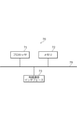
- FIG. 6 is a diagram showing an example of the hardware configuration of the information terminal 12.
- the information terminal 12 for example, includes a processor 61, a memory 62, a wireless communication interface 63, a wired communication interface 64, and a user interface 65, as shown in FIG.
- the processor 61, the memory 62, the user interface 65, the wireless communication interface 63 and the wired communication interface 64 are connected by, for example, a bus 69.
- the processor 61 is a circuit that performs signal processing, for example, a CPU that controls the entire information terminal 12.
- the processor 61 may be realized by another digital circuit such as FPGA. Further, the processor 61 may be realized by combining a plurality of digital circuits.
- the memory 62 includes, for example, a main memory and an auxiliary memory.
- the main memory is, for example, RAM.
- the main memory is used as a work area for the processor 61.
- the auxiliary memory is a non-volatile memory such as a magnetic disk, an optical disk, or a flash memory.
- Various programs for operating the information terminal 12 are stored in the auxiliary memory.
- the program stored in the auxiliary memory is loaded into the main memory and executed by the processor 61.
- auxiliary memory may include a portable memory that can be removed from the information terminal 12.
- Portable memories include memory cards such as USB (Universal Serial Bus) flash drives and SD (Secure Digital) memory cards, and external hard disk drives.
- the wireless communication interface 63 is a communication interface that performs wireless communication with the outside of the information terminal 12.
- the wireless communication interface 63 is controlled by the processor 61.
- the communication interface for communication with the breath sound measuring device 1 in the information terminal 12 is included in, for example, the wireless communication interface 63.
- the wireless communication interface 63 includes a communication interface capable of short-range wireless communication with the respiratory sound measuring device 1.
- the wired communication interface 64 is a communication interface that performs wired communication with the outside of the information terminal 12.
- the wired communication interface 64 is controlled by the processor 61. When the information terminal 12 does not perform wired communication, the wired communication interface 64 may be omitted from the information terminal 12.
- the user interface 65 includes, for example, an input device that accepts operation input from the user, an output device that outputs information to the user, and the like.
- the input device can be realized by, for example, a key (for example, a keyboard) or a remote controller.
- the output device can be realized by, for example, a display or a speaker. Further, an input device and an output device may be realized by a touch panel or the like.
- the user interface 65 is controlled by the processor 61.
- the reception of the measurement data from the breath sound measuring device 1 by the information terminal 12 is executed, for example, by the processor 61 controlling the wireless communication interface 63.
- the transmission of measurement data to the server 13 by the information terminal 12 and the reception of the analysis result from the server 13 by the information terminal 12 are executed, for example, by the processor 61 controlling the wired communication interface 64.
- the notification of the analysis result by the information terminal 12 is executed, for example, by the processor 61 controlling the user interface 65.
- FIG. 7 is a diagram showing an example of the hardware configuration of the server 13.
- the server 13 includes, for example, a processor 71, a memory 72, and a wired communication interface 73, as shown in FIG.
- the processor 71, the memory 72, and the wired communication interface 73 are connected by, for example, a bus 79.
- the processor 71 and the memory 72 are the same as the processor 61 and the memory 72 of the information terminal 12 shown in FIG.
- the wired communication interface 73 is a communication interface for performing wired communication with the outside of the server 13 (for example, the network 14).
- the wired communication interface 73 is controlled by the processor 71.
- the analysis based on the above measurement data is executed by, for example, the processor 71. Further, the reception of the measurement data and the transmission of the analysis result by the server 13 are executed by the processor 71 controlling the wired communication interface 73.
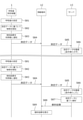
- FIG. 8 is a sequence diagram showing an example of processing in the breath sound information processing system 10. In the breath sound information processing system 10, for example, the process shown in FIG. 8 is executed.
- the respiratory sound measuring device 1 measures the respiratory sound according to the operation from the user (step S81). Next, the respiratory sound measuring device 1 detects wheezing based on the measurement data obtained by the measurement in step S81 (step S82). Next, the respiratory sound measuring device 1 notifies the user of the detection result of wheezing in step S82 (step S83).
- the breath sound measuring device 1 transmits the measurement data obtained by the measurement in step S81 to the information terminal 12 (step S84).
- the order of steps S82 and S83 and step S84 may be changed, or steps S82 and S84 may be executed in parallel.
- the information terminal 12 transmits the measurement data received in step S84 to the server 13 (step S85).
- the server 13 stores the measurement data received in step S85 in the memory 72 (step S86).
- Steps S81 to S86 are performed every time the user instructs the respiratory sound measuring device 1 to start the measurement.
- the server 13 accumulates a plurality of measurement data obtained by the breath sound measuring device 1.
- the server 13 determines whether or not the number of transmissions or the transmission frequency of the measurement data by the respiratory sound measuring device 1 satisfies the predetermined condition, and if the number of transmissions or the transmission frequency satisfies the predetermined condition, the step. Move to S87.
- step S86 the number of transmissions or the transmission frequency satisfies a predetermined condition, and the server 13 shifts to step S87.
- the server 13 proceeds to step S87, the server 13 performs analysis based on the accumulated measurement data (step S87) and transmits the analysis result to the information terminal 12 (step S88).
- the server 13 accumulates when the number of measurement data received from the information terminal 12 (the number of times the measurement data is transmitted by the breathing sound measuring device 1) reaches the threshold N after the analysis result is finally transmitted to the information terminal 12.
- the analysis is performed based on the N measurement data, and the analysis result is transmitted to the information terminal 12.
- N is a natural number of 2 or more.
- the server 13 when the number of times of measurement data received within a predetermined period (frequency of transmission of measurement data by the breathing sound measuring device 1) reaches the threshold value M, the server 13 performs analysis based on the accumulated M measurement data and analyzes the data. The result may be transmitted to the information terminal 12.
- M is a natural number of 2 or more.
- the predetermined period may be, for example, a fixed period retroactively from the present to the past (for example, the past one month) or a month including the present (for example, if the present is July 9th, during that July). good.
- the information terminal 12 displays the analysis result received in step S88 (step S89).
- the user of the respiratory sound measuring device 1 can refer to the analysis result on the server 13 based on the respiratory sound measurement data, in addition to the wheezing result notified by step S83. Therefore, it is possible to obtain detailed information such as aura and seizures of wheezing as well as the presence or absence of wheezing at the time of measurement.
- the user presents the analysis result at the time of medical treatment by a doctor more appropriate medical treatment becomes possible.
- the server 13 transmits the analysis result to the information terminal 12 when the number of transmissions or the transmission frequency of the measurement data by the respiratory sound measuring device 1 satisfies a predetermined condition, so that the respiratory sound measuring device 1 can transmit the analysis result. It is possible to improve the motivation of users to make continuous measurements.
- the motivation of the user of the breath sound measuring device 1 to continuously perform measurement by improving the motivation of the user of the breath sound measuring device 1 to continuously perform measurement, more measurement data can be accumulated in the server 13, and measurement data can be accumulated not only in an abnormal situation but also in normal times. Can be done. Therefore, the accuracy of analysis on the server 13 can be improved. As a result, the motivation of the user of the breath sound measuring device 1 to continuously perform the measurement can be further improved.
- ⁇ Modification 1> For example, in the breathing sound information processing system 10 shown in FIG. 1, when the breathing sound measuring device 1 can communicate with the network 14 without going through the information terminal 12, the breathing sound measuring device 1 does not go through the information terminal 12. Measurement data may be transmitted to the server 13.
- ⁇ Modification 2> The configuration of the measurement unit 3 shown in FIG. 4 is an example, and various modifications are possible. For example, when the above noise reduction is not performed, the sound measuring device M2 or the like may be omitted from the measuring unit 3.
- the wireless communication unit 7 of the breathing sound measuring device 1 is a communication interface for short-range wireless communication
- the wireless communication unit 7 may be a communication interface such as a wireless LAN.
- the respiratory sound measuring device 1 may be provided with a communication interface capable of wired communication with the information terminal 12 instead of the wireless communication unit 7 or in addition to the wireless communication unit 7.
- the communication interface capable of wired communication is, for example, a USB communication interface.
- the wired communication interface 64 of the information terminal 12 shown in FIG. 6 also includes the USB communication interface, and the breathing sound measuring device 1 and the information terminal 12 are connected by a USB cable.
- the breath sound measuring device 1 transmits measurement data and the like to the information terminal 12 by USB.
- Respiratory sound measuring device 1a Head part 1b Grip part 1c Wheezing notification lamp 1d Wheezing non-notification lamp 2 Housing 3 Measuring unit 3a Pressure receiving unit 4 General control unit 5 Battery 6 Drive unit 7 Wireless communication unit 10 Respiratory sound information processing system 12 Information terminal 13 Server 14 Network 31 First housing 31h, 34h Opening 32 Housing cover 34 Second housing 41 Wheezing judgment unit 42 Control unit 61, 71 Processor 62, 72 Memory 63 Wireless communication interface 64, 73 Wired communication interface 65 User interface 69 , 79 Bus M1, M2 Wheeze measuring instrument SP1, SP2 Housing space
Landscapes
- Health & Medical Sciences (AREA)
- Life Sciences & Earth Sciences (AREA)
- Physics & Mathematics (AREA)
- Public Health (AREA)
- Surgery (AREA)
- Acoustics & Sound (AREA)
- Veterinary Medicine (AREA)
- Engineering & Computer Science (AREA)
- Biomedical Technology (AREA)
- Heart & Thoracic Surgery (AREA)
- Medical Informatics (AREA)
- Molecular Biology (AREA)
- General Health & Medical Sciences (AREA)
- Animal Behavior & Ethology (AREA)
- Pulmonology (AREA)
- Physiology (AREA)
- Pathology (AREA)
- Biophysics (AREA)
- Measurement Of The Respiration, Hearing Ability, Form, And Blood Characteristics Of Living Organisms (AREA)
- Investigating Or Analysing Biological Materials (AREA)
Abstract
測定結果に基づくより有益な情報を利用者に提供することができる技術を提供する。 本発明の一側面に係る呼吸音情報処理システムは、呼吸音測定装置と、サーバと、を含む。前記呼吸音測定装置は、被測定者の呼吸音を測定して得られた測定データに基づく喘鳴の検知結果を利用者に通知し、前記測定データを送信する。前記サーバは、前記呼吸音測定装置によって送信された測定データに基づく解析を行い、解析結果を前記利用者の情報端末へ送信する。
Description
本発明は、呼吸音情報処理システム及び呼吸音測定装置に関する。
従来、喘息発作の特徴である喘鳴を検知する喘鳴センサが知られている。例えば、特許文献1には、被測定者の呼吸音を検知して、その呼吸音を表す時系列の呼吸音信号を取得し、被測定者の喘鳴の発生頻度の時間推移を表示する装置が開示されている。
しかしながら、喘鳴センサは、喘鳴の有無を判定できるが、喘息の状況を総合的に判定できるものではない。このため、従来の喘鳴センサにより得られる喘鳴の有無の情報のみでは、利用者において喘鳴測定を継続的に行うモチベーションが得られない場合がある。
本発明は、一側面では、このような実情を鑑みてなされたものであり、その目的は、測定結果に基づくより有益な情報を利用者に提供することができる技術を提供することである。
本発明は、上記の課題を解決するために、以下の構成を採用する。
すなわち、本発明の一側面に係る呼吸音情報処理システムは、被測定者の呼吸音を測定して得られた測定データに基づく喘鳴の検知結果を利用者に通知し、前記測定データを送信する呼吸音測定装置と、前記呼吸音測定装置によって送信された測定データに基づく解析を行い、解析結果を前記利用者の情報端末へ送信するサーバと、を含む。
上記構成では、呼吸音測定装置ではなくサーバにおいて、呼吸音測定装置において得られた測定データに基づく解析を行い、測定時の喘鳴の有無だけでなく、より有益な解析結果を利用者に提供することができる。また、この解析結果を利用者が医師に提供することにより、より適切な診療が可能になる。
上記一側面に係る呼吸音情報処理システムにおいて、前記サーバは、前記呼吸音測定装置によって送信された複数の測定データに基づく解析結果を前記利用者の情報端末へ送信してもよい。当該構成によれば、利用者は、測定を行うほど高精度な解析結果が得られるため、継続的な測定に対する利用者のモチベーションを向上させることができる。
上記一側面に係る呼吸音情報処理システムにおいて、前記サーバは、前記呼吸音測定装置による前記測定データの送信回数が所定の条件を満たした場合に、前記複数の測定データに基づく解析結果を前記情報端末へ送信してもよい。当該構成によれば、利用者は、測定データの送信回数が所定の条件を満たさないと解析結果が得られないため、継続的な測定に対する利用者のモチベーションを向上させることができる。
上記一側面に係る呼吸音情報処理システムにおいて、前記サーバは、前記呼吸音測定装置による前記測定データの送信頻度が所定の条件を満たした場合に、前記複数の測定データに基づく解析結果を前記情報端末へ送信してもよい。当該構成によれば、利用者は、測定データの送信頻度が所定の条件を満たさないと解析結果が得られないため、継続的な測定に対する利用者のモチベーションを向上させることができる。
上記一側面に係る呼吸音情報処理システムにおいて、前記呼吸音測定装置は、前記利用者の情報端末を介して前記測定データを送信してもよい。当該構成によれば、呼吸音測定装置自体がサーバと通信する構成を有していなくても、情報端末を介して測定データをサーバへ送信することが可能になる。
上記一側面に係る呼吸音情報処理システムにおいて、前記サーバは、前記解析結果が所定の条件を満たした場合に前記解析結果を前記情報端末へ送信してもよい。当該構成によれば、利用者にとって重要な解析結果が出たり、過去の解析結果とは異なる解析結果が出たりした場合に解析結果を利用者に提供することができる。
本発明の一側面に係る呼吸音測定装置は、被測定者の呼吸音を測定するための音測定部と、前記音測定部の測定により得られた測定データに基づく喘鳴の検知結果を利用者に通知する通知部と、前記測定データを、前記測定データに基づく解析を行うサーバへ送信する送信部と、を備える。
以下、本発明の一側面に係る実施の形態を、図面に基づいて説明する。
(実施の形態)
<実施の形態の一例である呼吸音情報処理システム10の構成>
図1は、実施の形態の一例である呼吸音情報処理システム10の構成を示す図である。
<実施の形態の一例である呼吸音情報処理システム10の構成>
図1は、実施の形態の一例である呼吸音情報処理システム10の構成を示す図である。
図1に示すように、呼吸音情報処理システム10は、呼吸音測定装置1と、情報端末12と、サーバ13と、を含む。
呼吸音測定装置1は、ヘッド部1aを被測定者の体表面(肌)に押し当てて被測定者の呼吸音を測定するものである。喘息を患う者の呼吸音には喘鳴が含まれるため、呼吸音測定装置1が測定した呼吸音から被測定者の喘息等の容体を知ることができる。
呼吸音測定装置1は、呼吸音の測定により測定データを得る。この測定データは、例えば、呼吸音の測定により得られた呼吸音の波形を示すデータである。又は、測定データは、呼吸音の測定により得られた呼吸音の波形の特徴量(例えばピーク値、ピークのタイミングや頻度等)を示すデータであってもよい。又は、測定データは、喘鳴のレベルを3段階以上で示すデータなどであってもよい。
呼吸音測定装置1は、得られた測定データに基づいて喘鳴を検知し、喘鳴の検知結果を利用者に通知する。一例として、呼吸音測定装置1は、喘鳴を検知したことを通知するための喘鳴有通知ランプ1cと、喘鳴を検知しなかったことを示す喘鳴無通知ランプ1dと、を有する。喘鳴有通知ランプ1c及び喘鳴無通知ランプ1dのそれぞれは、例えばLED(Light Emitting Diode)などの光源である。また、測定データが、喘鳴のレベルを5段階(例えば「1」~「5」)で示すデータであるとする。呼吸音測定装置1は、測定データが示す喘鳴のレベルが閾値(例えば「3」)以上であれば喘鳴が有ると判定して喘鳴有通知ランプ1cを点灯させ、測定データが示す喘鳴のレベルが閾値未満であれば喘鳴が無いと判定して喘鳴無通知ランプ1dを点灯させる。
ただし、呼吸音測定装置1は、喘鳴の検知結果の通知を、ランプの点灯に限らず、音声出力、画面表示、又は振動などによって行ってもよい。又は、呼吸音測定装置1は、情報端末12との間で通信を行うことにより、喘鳴の検知結果の通知を情報端末12から行うようにしてもよい。
また、呼吸音測定装置1は、情報端末12との間で通信が可能である。図1の例では、呼吸音測定装置1は情報端末12との間で無線通信が可能である。呼吸音測定装置1は、情報端末12と通信を行うことにより、呼吸音の測定により得られた測定データをサーバ13へ送信する。呼吸音測定装置1がサーバ13へ送信する測定データは、上記の喘鳴の検知に用いた測定データであって、喘鳴の検知結果よりも詳細な(情報量の多い)データである。
情報端末12は、呼吸音測定装置1の利用者が所持する情報端末である。図1の例では情報端末12はスマートフォンであるが、情報端末12は、スマートフォンに限らず、タブレット端末やパーソナルコンピュータなどであってもよい。
情報端末12は、ネットワーク14を介してサーバ13と通信可能である。ネットワーク14は、例えばWAN(Wide Area Network)である。情報端末12とネットワーク14との間の通信は、有線LAN(Local Area Network)などの有線通信であってもよいし、無線LANなどの無線通信であってもよい。
情報端末12は、呼吸音測定装置1と通信を行うことにより、呼吸音測定装置1から測定データを受信する。そして、情報端末12は、受信した測定データを、ネットワーク14を介してサーバ13へ送信する。
サーバ13は、ネットワーク14を介して情報端末12と通信を行うことにより、呼吸音測定装置1から送信された測定データを受信する。そして、サーバ13は、受信した測定データに基づく解析を行う。サーバ13による解析は、測定データに基づく、被測定者の喘息等の容体に関する解析である。
例えば、サーバ13による解析は、喘鳴の前兆又は発作の検知や、呼吸の強弱や頻度などの解析や、被測定者の容体が通院を要するものであるかの判定や、被測定者の容体が通院を継続すべきものか否かの判定などである。
また、サーバ13による解析は、特定のアルゴリズムに基づくものであってもよいし、不特定の被測定者の測定データとその測定データに基づく情報(例えば診察結果など)とのセットを多数用いて学習済みのAI(Artificial Intelligence)などに基づくものであってもよい。
また、サーバ13は、ネットワーク14を介して情報端末12と通信を行うことにより、測定データに基づく解析結果を情報端末12へ送信する。情報端末12は、サーバ13から受信した解析結果を、画面表示や音声出力によって利用者に通知する。
なお、サーバ13は、ネットワーク14に接続された1台のサーバ装置であってもよいし、ネットワーク14に接続された1台以上のサーバ装置により実現される仮想サーバであってもよい。
<呼吸音測定装置1が利用される場面>
図2は、呼吸音測定装置1が利用される場面の一例を示す図である。被測定者の呼吸音を測定する際、呼吸音測定装置1の利用者(図1では親)は、図1に示すように、呼吸音測定装置1を片手で把持して、被測定者(図1では幼児)の体表面にヘッド部1aを指で押し当てる。なお、ヘッド部1aは、呼吸音測定装置1を把持する手とは別の手の指によって体表面に押し当てられてもよい。
図2は、呼吸音測定装置1が利用される場面の一例を示す図である。被測定者の呼吸音を測定する際、呼吸音測定装置1の利用者(図1では親)は、図1に示すように、呼吸音測定装置1を片手で把持して、被測定者(図1では幼児)の体表面にヘッド部1aを指で押し当てる。なお、ヘッド部1aは、呼吸音測定装置1を把持する手とは別の手の指によって体表面に押し当てられてもよい。
<呼吸音測定装置1の概略構成>
図3は、呼吸音測定装置1の概略構成の一例を示す側面図である。図3に示すように、呼吸音測定装置1は、樹脂又は金属等の筐体で構成された棒状の把持部1bを有し、この把持部1bの一端側にはヘッド部1aが設けられている。
図3は、呼吸音測定装置1の概略構成の一例を示す側面図である。図3に示すように、呼吸音測定装置1は、樹脂又は金属等の筐体で構成された棒状の把持部1bを有し、この把持部1bの一端側にはヘッド部1aが設けられている。
把持部1bの内部には、呼吸音測定装置1の全体を統括制御する統括制御部4と、動作に要する電圧を供給する電池5と、喘鳴有通知ランプ1c及び喘鳴無通知ランプ1dを駆動する駆動部6と、情報端末12との間で無線通信を行う無線通信部7と、を備える。図3においては喘鳴有通知ランプ1c及び喘鳴無通知ランプ1dの図示を省略している。無線通信部7は、Bluetooth(登録商標)等の近距離無線通信が可能な通信インタフェースである。無線通信部7は、情報端末12の送信部の一例である。喘鳴有通知ランプ1c、喘鳴無通知ランプ1d、及び駆動部6は、情報端末12の通知部の一例である。
統括制御部4は、各種のプロセッサ、RAM(Random Access Memory)、及びROM(Read Only Memory)等を含み、プログラムにしたがって呼吸音測定装置1の各ハードウェアの制御等を行う。統括制御部4のROMには、呼吸音測定装置1を動作させるためのプログラムが記憶されている。
各種のプロセッサとしては、プログラムを実行して各種処理を行う汎用的なプロセッサであるCPU(Central Processing Unit)、FPGA(Field Programmable Gate Array)等の製造後に回路構成を変更可能なプロセッサであるプログラマブルロジックデバイス(Programmable Logic Device:PLD)、又はASIC(Application Specific Integrated Circuit)等の特定の処理を実行させるために専用に設計された回路構成を有するプロセッサである専用電気回路等が含まれる。
これら各種のプロセッサの構造は、より具体的には、半導体素子等の回路素子を組み合わせた電気回路である。
統括制御部4は、各種のプロセッサのうちの1つで構成されてもよいし、同種又は異種の2つ以上のプロセッサの組み合わせ(例えば、複数のFPGAの組み合わせ又はCPUとFPGAの組み合わせ)で構成されてもよい。
ヘッド部1aには、把持部1bの長手方向とは異なる方向の一方側(図3においては下方側)へ突出する測定ユニット3が設けられている。測定ユニット3の先端には、被測定者である生体の体表面Sに接触されて体表面Sからの圧力を受ける受圧部3aが設けられている。
呼吸音測定装置1は、使用者の手Haの例えば人差し指がヘッド部1aにおける測定ユニット3の背面に置かれた状態で、測定ユニット3の受圧部3aがこの人差し指によって体表面Sに押圧されて使用される。
<図3に示す呼吸音測定装置1におけるA-A線に沿った断面模式図>
図4は、図3に示す呼吸音測定装置1におけるA-A線に沿った断面模式図である。
図4は、図3に示す呼吸音測定装置1におけるA-A線に沿った断面模式図である。
図4に示すように、測定ユニット3は、音を測定する第一の音測定器M1と、第一の音測定器M1を内部の収容空間SP1に収容し、且つ生体の体表面Sに押圧された状態にて体表面Sによって塞がれる開口31hを有する有底筒状の第一ハウジング31と、開口31hを第一ハウジング31の外側から閉じると共に第一ハウジング31を覆うハウジングカバー32と、音を測定する第二の音測定器M2と、第二の音測定器M2を収容する収容空間SP2を形成しかつ開口34hを有する第二ハウジング34と、を備える。
測定ユニット3は、ハウジングカバー32の一部が露出された状態にて、ヘッド部1aを構成する筐体2に形成された開口部に嵌合されて、筐体2に固定されている。
ハウジングカバー32の筐体2からの露出部分の先端部は平面又は曲面となっており、この平面又は曲面が受圧部3aを構成している。筐体2は、音を透過可能な樹脂等によって構成されている。
第一の音測定器M1は、呼吸音を測定するためのものであり、例えば、呼吸音の周波数域(一般的には10Hz以上1kHz以下)よりも広い帯域(例えば10Hz以上10kHz以下の周波数域)の音を測定するMEMS(Micro Electro Mechanical Systems)型マイクロフォン又は静電容量型マイクロフォン等で構成されている。第一の音測定器M1は、音測定部の一例である。
第一の音測定器M1は、図示省略のリード線等によって図3に示す統括制御部4と電気的に接続されており、測定した呼吸音の信号を統括制御部4に伝達する。
呼吸音測定装置1の使用時においては、ハウジングカバー32の受圧部3aが体表面Sに接触し、体表面Sからの圧力によって、収容空間SP1が、ハウジングカバー32を介して体表面Sにより密閉された状態(以下、この状態を密閉状態という)になる。
そして、生体から体表面Sに伝わる呼吸音によって受圧部3aが振動すると、この振動によって収容空間SP1の内圧が変動し、この内圧変動によって、呼吸音に応じた電気信号が第一の音測定器M1によって測定されることになる。
第一ハウジング31は、図4中の下方向に向かって略凸型の形状であり、樹脂又は金属等の空気より音響インピーダンスが高くかつ剛性の高い材料によって構成されている。第一ハウジング31は、密閉状態において、収容空間SP1の内部に、外部から音が伝わらないように、第一の音測定器M1の測定周波数帯の音を反射する材料にて構成される。
ハウジングカバー32は、有底筒状の部材であり、その中空部の形状は、第一ハウジング31の外壁形状とほぼ一致している。
ハウジングカバー32は、音響インピーダンスが人体、空気、又は、水に近い素材でかつ生体適合性の良い可撓性を有する材料によって構成される。ハウジングカバー32の材料としては、例えばシリコーン又はエラストマ等が用いられる。
第二の音測定器M2は、第一ハウジング31の周囲の音(人の声等の環境音、或いは、装置と生体又は衣服との間の擦れ音等)を測定するためのものであり、例えば、呼吸音の周波数域よりも広い帯域(例えば10Hz以上10kHz以下の周波数域)の音を測定するMEMS型マイクロフォン又は静電容量型マイクロフォン等で構成されている。
第二の音測定器M2は、図示省略のリード線等によって図3に示す統括制御部4と電気的に接続されており、測定した周囲音の信号を統括制御部4に伝達する。
第二の音測定器M2は、第一ハウジング31の受圧部3a側と反対側の面に固定されている。第二の音測定器M2の周囲は、第二ハウジング34によって覆われている。第二ハウジング34は、呼吸音測定装置1の周囲で発生する音が第二の音測定器M2を収容する収容空間SP2に侵入しやすいような素材(例えば樹脂)によって構成されている。
第二ハウジング34には開口34hが形成されている。このため、この開口34hからも呼吸音測定装置1の周囲で発生する音が侵入しやすい構造となっている。
<統括制御部4の構成>
図5は、統括制御部4の構成の一例を示す図である。統括制御部4のプロセッサは、喘鳴検出プログラムを実行することで、喘鳴判定部41及び制御部42として動作する。
図5は、統括制御部4の構成の一例を示す図である。統括制御部4のプロセッサは、喘鳴検出プログラムを実行することで、喘鳴判定部41及び制御部42として動作する。
喘鳴判定部41は、受圧部3aが被測定者の体表面Sに接触された状態にて、例えば把持部1bに設けられた喘鳴の検出処理の開始を指示するための操作部材(図示省略)が操作されて喘鳴の検出処理の開始指示がなされた場合に、第一の音測定器M1により測定される呼吸音の信号と、第二の音測定器M2により測定される周囲音の信号と、を順次取得する。以下では、上記の開始指示がなされてから第一の音測定器M1及び第二の音測定器M2によって最初に音が測定されたタイミングを測定開始時点という。
喘鳴判定部41は、開始指示がなされて以降に順次取得した呼吸音の信号及び周囲音の信号(測定データ)に基づいて、被測定者の呼吸音に喘鳴が含まれるか否か、すなわち喘鳴の有無を判定する処理(以下、喘鳴判定処理という)を行う。
喘鳴判定部41は、例えば、予め決められた処理時間(例えば1秒等)分の呼吸音の信号及び周囲音の信号(処理対象信号群という)が蓄積された時点で、この処理対象信号群に基づいて、喘鳴の有無を判定する。
喘鳴判定部41は、例えば、処理対象信号群に含まれる呼吸音の信号に混入する呼吸音以外のノイズを、周囲音の信号に基づいて除去する。そして、喘鳴判定部41は、ノイズ除去後の呼吸音の信号に基づいて喘鳴の有無を判定する。
呼吸音の信号に基づく喘鳴の有無の判定方法は特に限定されないが、例えば特許文献1に記載の方法等を採用すればよい。喘鳴判定部41は、新たな処理対象信号群が蓄積される毎にこのような処理を行って、喘鳴の有無を処理時間毎に判定する。
制御部42は、開始指示がなされた後、測定開始時点からの経過時間が予め決められた所定時間T1に達した場合、第一の音測定器M1及び第二の音測定器M2による音の測定を終了させ、且つ喘鳴判定処理の結果(喘鳴有り又は喘鳴無し)を通知する。制御部42は、例えば、駆動部6を制御して喘鳴有通知ランプ1c又は喘鳴無通知ランプ1dを点灯させることにより、この結果の通知を行う。なお、この通知は、測定開始時点からの経過時間が予め決められた所定時間T1に達する前であっても、喘鳴判定部41により被測定者の呼吸音に喘鳴が含まれると判定された時点で行われてもよい。
上記の所定時間T1とは、呼吸音に喘鳴が含まれているか否かを判断するために必要とされる時間である。喘鳴の有無を判定するためには、約5呼吸分の呼吸音の信号があることが望ましいとされる。
安静時における5呼吸に必要な時間は、6歳未満の乳幼児であればおおよそ5~10秒であり、6歳以上13歳未満の子供であればおおよそ13~17秒であり、13歳以上60歳未満の大人であればおおよそ17~25秒であり、60歳以上の大人であればおおよそ10~30秒である。したがって、所定時間T1は、例えば10秒以上30秒以下の範囲から選ばれる値とされる。
呼吸音測定装置1の使用対象年齢を例えば6歳未満に限定するのであれば、所定時間T1は10秒とするのが好ましい。また、呼吸音測定装置1の使用対象年齢を例えば13歳未満に限定するのであれば、所定時間T1は20秒とするのが好ましい。また、呼吸音測定装置1の使用対象年齢を例えば60歳未満に限定するのであれば、所定時間T1は25秒とするのが好ましい。また、呼吸音測定装置1の使用対象年齢を限定しないのであれば、所定時間T1は30秒とするのが好ましい。呼吸音測定装置1は、本人によって喘息の症状が判断しにくい13未満の年齢の子供にとって最も有効な製品と考えられる。
また、制御部42は、無線通信部7を制御して、喘鳴判定処理に用いた測定データを情報端末12へ送信する。測定データの送信は、測定の終了後に自動的に行われてもよいし、呼吸音測定装置1又は情報端末12に対して利用者からの特定の操作があった場合に行われてもよい。
<情報端末12のハードウェア構成>
図6は、情報端末12のハードウェア構成の一例を示す図である。情報端末12は、例えば、図6に示すように、プロセッサ61と、メモリ62と、無線通信インタフェース63と、有線通信インタフェース64と、ユーザインタフェース65と、を備える。プロセッサ61、メモリ62、ユーザインタフェース65、無線通信インタフェース63及び有線通信インタフェース64は、例えばバス69によって接続される。
図6は、情報端末12のハードウェア構成の一例を示す図である。情報端末12は、例えば、図6に示すように、プロセッサ61と、メモリ62と、無線通信インタフェース63と、有線通信インタフェース64と、ユーザインタフェース65と、を備える。プロセッサ61、メモリ62、ユーザインタフェース65、無線通信インタフェース63及び有線通信インタフェース64は、例えばバス69によって接続される。
プロセッサ61は、信号処理を行う回路であり、例えば情報端末12の全体の制御を司るCPUである。なお、プロセッサ61は、FPGAなどの他のデジタル回路により実現されてもよい。また、プロセッサ61は、複数のデジタル回路を組み合わせて実現されてもよい。
メモリ62には、例えばメインメモリ及び補助メモリが含まれる。メインメモリは、例えばRAMである。メインメモリは、プロセッサ61のワークエリアとして使用される。
補助メモリは、例えば磁気ディスク、光ディスク、フラッシュメモリなどの不揮発性メモリである。補助メモリには、情報端末12を動作させる各種のプログラムが記憶されている。補助メモリに記憶されたプログラムは、メインメモリにロードされてプロセッサ61によって実行される。
また、補助メモリは、情報端末12から取り外し可能な可搬型のメモリを含んでもよい。可搬型のメモリには、USB(Universal Serial Bus)フラッシュドライブやSD(Secure Digital)メモリカードなどのメモリカードや、外付けハードディスクドライブなどがある。
無線通信インタフェース63は、情報端末12の外部との間で無線通信を行う通信インタフェースである。無線通信インタフェース63は、プロセッサ61により制御される。情報端末12における呼吸音測定装置1との通信のための通信インタフェースは、例えば無線通信インタフェース63に含まれる。一例としては、無線通信インタフェース63は、呼吸音測定装置1との間で近距離無線通信が可能な通信インタフェースを含む。
有線通信インタフェース64は、情報端末12の外部との間で有線通信を行う通信インタフェースである。有線通信インタフェース64は、プロセッサ61により制御される。なお、情報端末12が有線通信を行わない場合、情報端末12から有線通信インタフェース64を省いた構成としてもよい。
ユーザインタフェース65は、例えば、利用者からの操作入力を受け付ける入力デバイスや、利用者へ情報を出力する出力デバイスなどを含む。入力デバイスは、例えばキー(例えばキーボード)やリモコンなどにより実現することができる。出力デバイスは、例えばディスプレイやスピーカなどにより実現することができる。また、タッチパネルなどによって入力デバイス及び出力デバイスを実現してもよい。ユーザインタフェース65は、プロセッサ61により制御される。
情報端末12による呼吸音測定装置1からの測定データの受信は、例えばプロセッサ61が無線通信インタフェース63を制御することによって実行される。情報端末12によるサーバ13への測定データの送信や、情報端末12によるサーバ13からの解析結果の受信は、例えばプロセッサ61が有線通信インタフェース64を制御することによって実行される。情報端末12による解析結果の通知は、例えばプロセッサ61がユーザインタフェース65を制御することによって実行される。
<サーバ13のハードウェア構成>
図7は、サーバ13のハードウェア構成の一例を示す図である。サーバ13は、例えば、図7に示すように、プロセッサ71と、メモリ72と、有線通信インタフェース73と、を備える。プロセッサ71、メモリ72、及び有線通信インタフェース73は、例えばバス79により接続される。
図7は、サーバ13のハードウェア構成の一例を示す図である。サーバ13は、例えば、図7に示すように、プロセッサ71と、メモリ72と、有線通信インタフェース73と、を備える。プロセッサ71、メモリ72、及び有線通信インタフェース73は、例えばバス79により接続される。
プロセッサ71及びメモリ72は、図6に示した情報端末12のプロセッサ61及びメモリ72と同様である。有線通信インタフェース73は、サーバ13の外部(例えばネットワーク14)との間で有線通信を行う通信インタフェースである。有線通信インタフェース73は、プロセッサ71によって制御される。
上記の測定データに基づく解析は、例えばプロセッサ71によって実行される。また、サーバ13による測定データの受信や解析結果の送信は、プロセッサ71が有線通信インタフェース73を制御することによって実行される。
<呼吸音情報処理システム10における処理>
図8は、呼吸音情報処理システム10における処理の一例を示すシーケンス図である。呼吸音情報処理システム10においては、例えば図8に示す処理が実行される。
図8は、呼吸音情報処理システム10における処理の一例を示すシーケンス図である。呼吸音情報処理システム10においては、例えば図8に示す処理が実行される。
まず、呼吸音測定装置1が、利用者からの操作に応じて、呼吸音の測定を行う(ステップS81)。次に、呼吸音測定装置1が、ステップS81の測定により得られた測定データに基づいて喘鳴を検知する(ステップS82)。次に、呼吸音測定装置1が、ステップS82による喘鳴の検知結果を利用者に通知する(ステップS83)。
また、呼吸音測定装置1が、ステップS81の測定により得られた測定データを情報端末12へ送信する(ステップS84)。なお、ステップS82,S83と、ステップS84とは、順序を入れ替えてもよいし、並行して実行されてもよい。
次に、情報端末12が、ステップS84により受信した測定データをサーバ13へ送信する(ステップS85)。次に、サーバ13が、ステップS85によって受信した測定データをメモリ72に蓄積する(ステップS86)。
ステップS81~S86は、利用者が呼吸音測定装置1に対して測定の開始を指示するたびに行われる。これにより、サーバ13において、呼吸音測定装置1により得られた複数の測定データが蓄積される。ステップS86において、サーバ13は、呼吸音測定装置1による測定データの送信回数又は送信頻度が所定の条件を満たしたか否かを判断し、送信回数又は送信頻度が所定の条件を満たした場合にステップS87へ移行する。
図8の例では、2回目のステップS86において、送信回数又は送信頻度が所定の条件を満たし、サーバ13がステップS87へ移行したとする。サーバ13は、ステップS87へ移行すると、蓄積した複数の測定データに基づく解析を行い(ステップS87)、解析結果を情報端末12へ送信する(ステップS88)。
例えば、サーバ13は、最後に情報端末12へ解析結果を送信してから情報端末12から受信した測定データの回数(呼吸音測定装置1による測定データの送信回数)が閾値Nに達すると、蓄積したN個の測定データに基づく解析を行い、解析結果を情報端末12へ送信する。Nは2以上の自然数である。
又は、サーバ13は、所定期間内に受信した測定データの回数(呼吸音測定装置1による測定データの送信頻度)が閾値Mに達すると、蓄積したM個の測定データに基づく解析を行い、解析結果を情報端末12へ送信してもよい。Mは2以上の自然数である。所定期間とは、例えば、現在から過去に遡って一定期間(一例としては過去1カ月)や、現在を含む月(例えば現在が7月9日であればその7月中)などであってもよい。
このように、測定データの送信回数や送信頻度が所定の条件を満たした場合に解析を実行することで、サーバ13において、1回分の測定データだけでは難しい判断や確認が可能になる。
情報端末12は、ステップS88によって受信した解析結果を表示する(ステップS89)。これにより、呼吸音測定装置1の利用者は、ステップS83によって通知される喘鳴の結果とは別に、呼吸音の測定データに基づくサーバ13での解析結果を参照することができる。このため、測定時の喘鳴の有無だけではなく、喘鳴の前兆・発作などの詳細な情報を得ることができる。また、医師による診療時に利用者がこの解析結果を提示することで、より適切な診療が可能になる。
また、サーバ13は、呼吸音測定装置1による測定データの送信回数又は送信頻度が所定の条件を満たした場合に解析結果を情報端末12へ送信するようにすることで、呼吸音測定装置1の利用者が継続的に測定を行うモチベーションを向上させることができる。
また、呼吸音測定装置1の利用者が継続的に測定を行うモチベーションが向上することで、サーバ13において、より多くの測定データを蓄積できたり、異常時だけでなく平常時の測定データを蓄積したりすることができる。このため、サーバ13における解析の精度の向上を図ることができる。それにより、呼吸音測定装置1の利用者が継続的に測定を行うモチベーションをさらに向上させることができる。
<変形例1>
例えば図1に示した呼吸音情報処理システム10において、呼吸音測定装置1が情報端末12を介さずにネットワーク14と通信可能である場合、呼吸音測定装置1は、情報端末12を介さずにサーバ13へ測定データを送信してもよい。
例えば図1に示した呼吸音情報処理システム10において、呼吸音測定装置1が情報端末12を介さずにネットワーク14と通信可能である場合、呼吸音測定装置1は、情報端末12を介さずにサーバ13へ測定データを送信してもよい。
<変形例2>
図4に示した測定ユニット3の構成は一例であり、各種の変形が可能である。例えば、上記のノイズ除去を行わない場合は、測定ユニット3から音測定器M2などを省いた構成としてもよい。
図4に示した測定ユニット3の構成は一例であり、各種の変形が可能である。例えば、上記のノイズ除去を行わない場合は、測定ユニット3から音測定器M2などを省いた構成としてもよい。
<変形例3>
呼吸音測定装置1の無線通信部7が近距離無線通信の通信インタフェースである場合について説明したが、無線通信部7は無線LANなどの通信インタフェースであってもよい。また、無線通信部7に代えて、又は無線通信部7に加えて、情報端末12との間で有線通信が可能な通信インタフェースを呼吸音測定装置1に設けてもよい。
呼吸音測定装置1の無線通信部7が近距離無線通信の通信インタフェースである場合について説明したが、無線通信部7は無線LANなどの通信インタフェースであってもよい。また、無線通信部7に代えて、又は無線通信部7に加えて、情報端末12との間で有線通信が可能な通信インタフェースを呼吸音測定装置1に設けてもよい。
有線通信が可能な通信インタフェースは、一例としてはUSBの通信インタフェースである。この場合、図6に示した情報端末12の有線通信インタフェース64にもUSBの通信インタフェースを含め、呼吸音測定装置1と情報端末12とをUSBケーブルで接続する。呼吸音測定装置1は、USBによって測定データ等を情報端末12へ送信する。
以上、図面を参照しながら各種の実施の形態について説明したが、本発明はかかる例に限定されないことは言うまでもない。当業者であれば、特許請求の範囲に記載された範疇内において、各種の変更例又は修正例に想到し得ることは明らかであり、それらについても当然に本発明の技術的範囲に属するものと了解される。また、発明の趣旨を逸脱しない範囲において、上記実施の形態における各構成要素を任意に組み合わせてもよい。
なお、本出願は、2020年9月2日出願の日本特許出願(特願2020-147903)に基づくものであり、その内容は本出願の中に参照として援用される。
1 呼吸音測定装置
1a ヘッド部
1b 把持部
1c 喘鳴有通知ランプ
1d 喘鳴無通知ランプ
2 筐体
3 測定ユニット
3a 受圧部
4 統括制御部
5 電池
6 駆動部
7 無線通信部
10 呼吸音情報処理システム
12 情報端末
13 サーバ
14 ネットワーク
31 第一ハウジング
31h,34h 開口
32 ハウジングカバー
34 第二ハウジング
41 喘鳴判定部
42 制御部
61,71 プロセッサ
62,72 メモリ
63 無線通信インタフェース
64,73 有線通信インタフェース
65 ユーザインタフェース
69,79 バス
M1,M2 音測定器
SP1,SP2 収容空間
1a ヘッド部
1b 把持部
1c 喘鳴有通知ランプ
1d 喘鳴無通知ランプ
2 筐体
3 測定ユニット
3a 受圧部
4 統括制御部
5 電池
6 駆動部
7 無線通信部
10 呼吸音情報処理システム
12 情報端末
13 サーバ
14 ネットワーク
31 第一ハウジング
31h,34h 開口
32 ハウジングカバー
34 第二ハウジング
41 喘鳴判定部
42 制御部
61,71 プロセッサ
62,72 メモリ
63 無線通信インタフェース
64,73 有線通信インタフェース
65 ユーザインタフェース
69,79 バス
M1,M2 音測定器
SP1,SP2 収容空間
Claims (7)
- 被測定者の呼吸音を測定して得られた測定データに基づく喘鳴の検知結果を利用者に通知し、前記測定データを送信する呼吸音測定装置と、
前記呼吸音測定装置によって送信された測定データに基づく解析を行い、解析結果を前記利用者の情報端末へ送信するサーバと、
を含む呼吸音情報処理システム。 - 請求項1記載の呼吸音情報処理システムであって、
前記サーバは、前記呼吸音測定装置によって送信された複数の測定データに基づく解析結果を前記情報端末へ送信する、
呼吸音情報処理システム。 - 請求項2記載の呼吸音情報処理システムであって、
前記サーバは、前記呼吸音測定装置による前記測定データの送信回数が所定の条件を満たした場合に、前記複数の測定データに基づく解析結果を前記情報端末へ送信する、
呼吸音情報処理システム。 - 請求項2記載の呼吸音情報処理システムであって、
前記サーバは、前記呼吸音測定装置による前記測定データの送信頻度が所定の条件を満たした場合に、前記複数の測定データに基づく解析結果を前記情報端末へ送信する、
呼吸音情報処理システム。 - 請求項1から4のいずれか1項記載の呼吸音情報処理システムであって、
前記呼吸音測定装置は、前記情報端末を介して前記測定データを送信する、
呼吸音情報処理システム。 - 請求項1から5のいずれか1項記載の呼吸音情報処理システムであって、
前記サーバは、前記解析結果が所定の条件を満たした場合に前記解析結果を前記情報端末へ送信する、
呼吸音情報処理システム。 - 被測定者の呼吸音を測定するための音測定部と、
前記音測定部の測定により得られた測定データに基づく喘鳴の検知結果を利用者に通知する通知部と、
前記測定データを、前記測定データに基づく解析を行うサーバへ送信する送信部と、
を備える呼吸音測定装置。
Applications Claiming Priority (2)
| Application Number | Priority Date | Filing Date | Title |
|---|---|---|---|
| JP2020147903A JP2022042442A (ja) | 2020-09-02 | 2020-09-02 | 呼吸音情報処理システム及び呼吸音測定装置 |
| JP2020-147903 | 2020-09-02 |
Publications (1)
| Publication Number | Publication Date |
|---|---|
| WO2022050002A1 true WO2022050002A1 (ja) | 2022-03-10 |
Family
ID=80492009
Family Applications (1)
| Application Number | Title | Priority Date | Filing Date |
|---|---|---|---|
| PCT/JP2021/029446 Ceased WO2022050002A1 (ja) | 2020-09-02 | 2021-08-06 | 呼吸音情報処理システム及び呼吸音測定装置 |
Country Status (2)
| Country | Link |
|---|---|
| JP (1) | JP2022042442A (ja) |
| WO (1) | WO2022050002A1 (ja) |
Citations (4)
| Publication number | Priority date | Publication date | Assignee | Title |
|---|---|---|---|---|
| JP2006259827A (ja) * | 2005-03-15 | 2006-09-28 | Matsushita Electric Ind Co Ltd | 健康管理システム |
| WO2019188799A1 (ja) * | 2018-03-27 | 2019-10-03 | 富士フイルム株式会社 | ダイエット計画管理装置、ダイエット計画管理システム、ダイエット計画管理方法、及びプログラム |
| WO2020021977A1 (ja) * | 2018-07-26 | 2020-01-30 | オムロンヘルスケア株式会社 | 提示装置、提示方法及び提示プログラム |
| JP2020112856A (ja) * | 2019-01-08 | 2020-07-27 | 株式会社電通 | 喘息予報システム |
-
2020
- 2020-09-02 JP JP2020147903A patent/JP2022042442A/ja active Pending
-
2021
- 2021-08-06 WO PCT/JP2021/029446 patent/WO2022050002A1/ja not_active Ceased
Patent Citations (4)
| Publication number | Priority date | Publication date | Assignee | Title |
|---|---|---|---|---|
| JP2006259827A (ja) * | 2005-03-15 | 2006-09-28 | Matsushita Electric Ind Co Ltd | 健康管理システム |
| WO2019188799A1 (ja) * | 2018-03-27 | 2019-10-03 | 富士フイルム株式会社 | ダイエット計画管理装置、ダイエット計画管理システム、ダイエット計画管理方法、及びプログラム |
| WO2020021977A1 (ja) * | 2018-07-26 | 2020-01-30 | オムロンヘルスケア株式会社 | 提示装置、提示方法及び提示プログラム |
| JP2020112856A (ja) * | 2019-01-08 | 2020-07-27 | 株式会社電通 | 喘息予報システム |
Also Published As
| Publication number | Publication date |
|---|---|
| JP2022042442A (ja) | 2022-03-14 |
Similar Documents
| Publication | Publication Date | Title |
|---|---|---|
| US9968329B2 (en) | Remote control of medical device using audio data | |
| CN109936999B (zh) | 使用家庭睡眠系统进行睡眠评估 | |
| CN101652101B (zh) | 采用多个传感器信号特征检测的用于医学感测装置的功率管理 | |
| US12357264B2 (en) | Wheezing detection device and wheezing detection program | |
| US20230078479A1 (en) | Real-time monitoring device for human body | |
| KR20120040429A (ko) | 사용자의 생체정보 분석을 통한 감정상태 분석장치 및 방법 | |
| CN103415248A (zh) | 睡眠评价装置和睡眠评价方法 | |
| US11278258B2 (en) | Biological sound measuring device, biological sound measurement support method, and biological sound measurement support program | |
| KR20220019651A (ko) | 중이액 검출 시스템 및 방법 | |
| US12036064B2 (en) | Biological sound measuring device, method for operating biological sound measuring device, and program for operating biological sound measuring device | |
| US12138105B2 (en) | Biological sound measurement device, control method for biological sound measurement device, and non-transitory recording medium storing control program for biological sound measurement device | |
| US12478315B2 (en) | Biological information analysis device, biological information analysis method, and biological information analysis system | |
| JP2010022572A (ja) | 生体情報検出装置 | |
| JP2022042442A (ja) | 呼吸音情報処理システム及び呼吸音測定装置 | |
| CN107773216B (zh) | 用于监控且用于影响人的睡眠的仪器和运行该仪器的方法 | |
| CN205729331U (zh) | 号脉仪控制电路、智能号脉仪、智能手环及移动终端 | |
| CN107622802A (zh) | 信息处理装置、信息处理方法及计算机可读记录介质 | |
| US12383221B2 (en) | Biological sound measuring device, biological sound measurement support method, and biological sound measurement support program | |
| KR20160071585A (ko) | 디지털 통각 측정 시스템 |
Legal Events
| Date | Code | Title | Description |
|---|---|---|---|
| 121 | Ep: the epo has been informed by wipo that ep was designated in this application |
Ref document number: 21864060 Country of ref document: EP Kind code of ref document: A1 |
|
| DPE2 | Request for preliminary examination filed before expiration of 19th month from priority date (pct application filed from 20040101) | ||
| NENP | Non-entry into the national phase |
Ref country code: DE |
|
| 122 | Ep: pct application non-entry in european phase |
Ref document number: 21864060 Country of ref document: EP Kind code of ref document: A1 |