WO2022045332A1 - 中継装置、端末及び中継方法 - Google Patents
中継装置、端末及び中継方法 Download PDFInfo
- Publication number
- WO2022045332A1 WO2022045332A1 PCT/JP2021/031696 JP2021031696W WO2022045332A1 WO 2022045332 A1 WO2022045332 A1 WO 2022045332A1 JP 2021031696 W JP2021031696 W JP 2021031696W WO 2022045332 A1 WO2022045332 A1 WO 2022045332A1
- Authority
- WO
- WIPO (PCT)
- Prior art keywords
- terminal
- relay
- base station
- relay device
- notification
- Prior art date
- Legal status (The legal status is an assumption and is not a legal conclusion. Google has not performed a legal analysis and makes no representation as to the accuracy of the status listed.)
- Ceased
Links
Images









Classifications
-
- H—ELECTRICITY
- H04—ELECTRIC COMMUNICATION TECHNIQUE
- H04W—WIRELESS COMMUNICATION NETWORKS
- H04W76/00—Connection management
- H04W76/10—Connection setup
-
- H—ELECTRICITY
- H04—ELECTRIC COMMUNICATION TECHNIQUE
- H04W—WIRELESS COMMUNICATION NETWORKS
- H04W12/00—Security arrangements; Authentication; Protecting privacy or anonymity
- H04W12/03—Protecting confidentiality, e.g. by encryption
- H04W12/037—Protecting confidentiality, e.g. by encryption of the control plane, e.g. signalling traffic
-
- H—ELECTRICITY
- H04—ELECTRIC COMMUNICATION TECHNIQUE
- H04W—WIRELESS COMMUNICATION NETWORKS
- H04W12/00—Security arrangements; Authentication; Protecting privacy or anonymity
- H04W12/06—Authentication
-
- H—ELECTRICITY
- H04—ELECTRIC COMMUNICATION TECHNIQUE
- H04W—WIRELESS COMMUNICATION NETWORKS
- H04W12/00—Security arrangements; Authentication; Protecting privacy or anonymity
- H04W12/08—Access security
-
- H—ELECTRICITY
- H04—ELECTRIC COMMUNICATION TECHNIQUE
- H04W—WIRELESS COMMUNICATION NETWORKS
- H04W12/00—Security arrangements; Authentication; Protecting privacy or anonymity
- H04W12/12—Detection or prevention of fraud
- H04W12/121—Wireless intrusion detection systems [WIDS]; Wireless intrusion prevention systems [WIPS]
- H04W12/122—Counter-measures against attacks; Protection against rogue devices
-
- H—ELECTRICITY
- H04—ELECTRIC COMMUNICATION TECHNIQUE
- H04W—WIRELESS COMMUNICATION NETWORKS
- H04W24/00—Supervisory, monitoring or testing arrangements
- H04W24/04—Arrangements for maintaining operational condition
-
- H—ELECTRICITY
- H04—ELECTRIC COMMUNICATION TECHNIQUE
- H04W—WIRELESS COMMUNICATION NETWORKS
- H04W76/00—Connection management
- H04W76/10—Connection setup
- H04W76/19—Connection re-establishment
-
- H—ELECTRICITY
- H04—ELECTRIC COMMUNICATION TECHNIQUE
- H04W—WIRELESS COMMUNICATION NETWORKS
- H04W76/00—Connection management
- H04W76/10—Connection setup
- H04W76/14—Direct-mode setup
-
- H—ELECTRICITY
- H04—ELECTRIC COMMUNICATION TECHNIQUE
- H04W—WIRELESS COMMUNICATION NETWORKS
- H04W88/00—Devices specially adapted for wireless communication networks, e.g. terminals, base stations or access point devices
- H04W88/02—Terminal devices
- H04W88/04—Terminal devices adapted for relaying to or from another terminal or user
Definitions
- the present invention relates to a relay device, a terminal, and a relay method that can be connected to a relay device instead of a base station.
- the Japan Meteorological Agency, etc. sends a disaster bulletin including information on the earthquake (for example, seismic intensity, epicenter, etc.) to a terminal owned by an individual via a network.
- the terminal communicates with the network via the base station corresponding to the authentication information registered in advance.
- the breaking news was not sent to the terminal.
- Patent Document 1 discloses that when the base station detects that communication is impossible, it considers that the cause of communication failure is a disaster and shifts to the disaster occurrence mode.
- Patent Document 1 does not describe the processing when a failure occurs in the base station. Further, when a failure occurs in the base station, it is conceivable to relay the communication between the terminal and the network by using the newly provided base station. However, in this case, the terminal needs to communicate with the base station that does not correspond to the authentication information in order to start the communication with the newly provided base station. At this time, the terminal may be connected to, for example, an inappropriate system for extracting information from the terminal, guiding to a malicious site, or distributing erroneous information.
- the present invention has been made in view of the above problems, and an object of the present invention is to prevent a terminal from being connected to an inappropriate system when a failure occurs in a base station.
- the relay system of the present invention is A transmission means for transmitting a connection request including authentication information to a terminal connected to a network via the base station when a failure occurs in the base station.
- a receiving means for receiving a notification to the effect that the connection is permitted from the terminal that has received the connection request, and When the receiving means notifies that the notification has been received, the relay means for relaying the communication between the terminal and the network, and the relay means. To prepare for.
- the terminal of the present invention is Connection means to connect to the base station, Communication that determines whether or not the connection request received from the relay device contains the authentication information, and if the connection request contains the authentication information, sends a notification to the relay device to the effect that the connection is permitted.
- the connecting means connects to the relay device in place of the base station after the communication means transmits the notification to the relay device.
- the relay method of the present invention is: When a failure occurs in a base station, a connection request including authentication information is sent to a terminal connected to the network via the base station. Receive a notification to the effect that the connection is permitted from the terminal that received the connection request, When the notification is received, the communication between the terminal and the network is relayed.
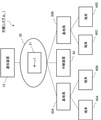
- FIG. 1 is a block diagram showing a configuration example of the relay system 1.
- FIG. 2 is a block diagram for explaining the details of the relay system 1.
- FIG. 3 is a block diagram showing the configuration of the terminal 40 described later.
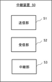
- FIG. 4 is a block diagram showing the configuration of the relay device 50 described later.
- FIG. 5 is a flowchart showing an operation example of the relay system 1.
- the relay system 1 includes a notification device 10, a network 20, base stations 30A, 30B, terminals 40A, 40B, 40C, 40D, and a relay device 50.
- a notification device 10 a network 20
- base stations 30A, 30B, terminals 40A, 40B, 40C, 40D base stations 30A, 30B, 40C, 40D
- a relay device 50 a relay device 50
- each of the base stations 30A and 30B is referred to as a base station 30.
- each of the terminals 40A, 40B, 40C, and 40D is referred to as a terminal 40.
- FIG. 1 is a block diagram showing a configuration example of the relay system 1 after a failure occurs in the base station 30A due to a disaster or the like.
- FIG. 2 is a block diagram showing a configuration example of the relay system 1 before a failure occurs in the base station 30A.
- the notification device 10 can communicate with the terminal 40 via the network 20, the base station 30, and the relay device 50. For example, when a disaster occurs, the notification device 10 transmits information about the disaster to the terminal 40.
- the information about the disaster here is, for example, the area where the disaster occurred and the damage situation.
- the notification device 10 communicates with the terminals 40A and 40B via the base station 30A before the failure occurs in the base station 30A. Further, the notification device 10 communicates with the terminals 40A and 40B via the relay device 50 after a failure occurs in the base station 30A.
- the network 20 relays communication between either one of the base station 30 and the relay device 50 and the notification device 10.
- the network 20 includes at least the server 21.
- the server 21 is, for example, an HSS (Home Subscriber Server).
- the server 21 communicates with the terminal 40 and shares the unique key with the terminal 40.
- the unique key is an IMSI (International Mobile Subscriber Identity) recorded on the SIM (Subscriber Identity Module) card of the terminal 40, or an IMEI (International Mobile Equipment Identity) generated from the terminal 40's IMEI (International Mobile Equipment Identity).
- the unique key is unique to the terminal 40.
- the unique key for the terminal 40A and the unique key for the terminal 40B are different from each other.
- the unique key possessed by the terminal 40A corresponds to the authentication information.
- the base station 30 is a general base station.
- the base station 30A relays the communication between the terminal 40A and the terminal 40B and the notification device 10 via the network 20.
- the base station 30B relays the communication between the terminal 40C and the terminal 40D and the notification device 10 via the network 20.
- the terminal 40 communicates with the notification device 10 via one of the base station 30 and the relay device 50 and the network 20.
- the terminal 40 shares a unique key with the server 21.
- the terminal 40 includes a connection unit 41, an update unit 42, and a communication unit 43.
- the connection unit 41 controls the route so that the terminal 40 connects to the network 20 via the base station 30.
- the update unit 42 of the terminal 40 updates the unique key at any time. For example, the terminal 40 updates the unique key at the time of starting the terminal 40 or at a preset cycle.
- the communication unit 43 of the terminal 40 transmits the updated unique key to the server 21. At this time, the communication unit 43 transmits the unique key to the server 21 of the network 20 via the base station 30 according to the route set by the connection unit 41.
- the unique key transmitted by the communication unit 43 is transferred to the relay device 50 by the server 21. That is, the communication unit 43 transmits the unique key to the relay device 50.
- connection portion 41 of the terminals 40A and 40B connects the network 20 and the terminals 40A and 40B via the base station 30A.
- the connection portion 41 of the terminals 40A and 40B connects the network 20 and the terminals 40A and 40B via the relay device 50.
- the connection unit 41 of the terminals 40C and 40D connects the network 20 and the terminals 40C and 40D via the base station 30B.
- the relay device 50 is provided so as to be able to communicate with the server 21 at all times. As shown in FIG. 4, the relay device 50 includes a transmission unit 51, a reception unit 52, and a relay unit 53. The relay device 50 communicates with the server 21 and acquires a unique key for each terminal 40. The relay device 50 does not connect to the terminal 40 as shown in FIG. 2 until the base station 30 fails. At this time, it is assumed that the relay device 50 communicates with the server 21 and acquires the unique key. Further, the unique key may be input to the relay device 50 by the administrator of the relay system 1 when the relay device 50 is not communicating with the server 21.
- the transmission unit 51 determines that a failure has occurred in the base station 30A
- the transmission unit 51 transmits a connection request including a unique key to the terminal 40. For example, when the transmission unit 51 is notified from the outside that a failure has occurred in the base station 30A, the transmission unit 51 determines that a failure has occurred in the base station 30A.
- the terminal 40 Upon receiving the connection request, the terminal 40 transmits a notification to the relay device 50 that the connection is permitted when the unique key included in the connection request matches the unique key possessed by the terminal 40.
- the receiving unit 52 receives a notification to the effect that the connection is permitted from the terminal 40 that has received the connection request.
- the relay unit 53 connects to the terminal 40 that has transmitted the notification and relays the communication between the terminal 40 and the network.
- connection unit 41 controls the route of the terminal 40 so that the terminal 40 connects to the network 20 via the base station 30.
- the communication unit 43 of the terminal 40 transmits the unique key generated by the update unit 42 to the server 21 (S101).
- the server 21 stores the unique keys received from the plurality of terminals 40 in association with each of the terminals 40 (S102).
- the server 21 transmits the unique key for each terminal 40 to the relay device 50 at a predetermined cycle (S103). As a result, the relay device 50 acquires the unique key for each terminal 40.
- the relay device 50 determines whether or not a failure has occurred in the base station 30 (S104). If a failure occurs in the base station 30, the operation of the base station 30 is stopped. For example, the network 20 determines that a failure has occurred in the base station 30 when there is no response from the base station 30. The relay device 50 determines whether or not there is a failure in the base station 30, for example, based on the notification from the network 20.
- the relay system 1 repeats the above-mentioned processes of S101 to S103.
- the transmission unit 51 of the relay device 50 transmits a connection request including a unique key for each terminal 40 to the terminal 40 located within a predetermined range. (S105). At this time, it is assumed that the terminal 40A and the terminal 40B are located within the predetermined range.
- the relay device 50 is stored at a position away from the base station 30 before the failure occurs in the base station 30. For example, when a failure occurs in the base station 30A, the relay device 50 is carried to the vicinity of the base station 30A, for example, on a vehicle of the administrator of the relay system 1.
- the terminal 40 determines whether or not the received connection request includes the unique key possessed by the terminal 40 (S106). As a result, the terminal 40 determines whether or not the relay device 50 has the unique key generated by the terminal 40.
- the terminal 40 rejects the connection request from the relay device 50 (S107). At this time, the operation of the relay system 1 ends.
- the terminal 40 When the connection request includes the unique key possessed by the terminal 40 (Yes in S106), the terminal 40 permits the connection request from the relay device 50 (S108). At this time, the terminal 40 transmits a notification to the reception unit 52 of the relay device 50 to the effect that the connection is permitted.
- the relay unit 53 relays the communication between the terminal 40 and the network 20 (S109).
- the terminals 40A and 40B connect to the network 20 via the relay device 50 instead of the base station 30A, and acquire information about the disaster from the notification device 10.
- the receiving unit 52 that has received the notification that the connection is permitted notifies the relay unit 53 that the notification has been received.
- the relay unit 53 determines that the reception unit 52 has received the notification that the connection is permitted. The operation of the relay system 1 has been described above.
- the relay device 50 of the relay system 1 includes a transmission unit 51, a reception unit 52, and a relay unit 53.
- the transmission unit 51 transmits a connection request including authentication information (unique key) to the terminal 40 connected to the network 20 via the base station 30.
- the receiving unit 52 receives a notification from the terminal 40 that has received the connection request to the effect that the connection is permitted.
- the relay unit 53 relays the communication between the terminal 40 and the network 20.
- the terminal 40 can communicate with the network 20.
- the terminal 40 communicates with the network 20 via the relay device 50 that stores common information (authentication information). Therefore, the terminal 40 of the relay system 1 can prevent communication with a device that does not have the authentication information. As a result, the terminal 40 is less likely to be connected to an inappropriate system for extracting information from the terminal, guiding to a malicious site, or distributing erroneous information.
- FIG. 6 is a block diagram showing a configuration example of the relay system 1A.
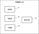
- FIG. 7 is a block diagram showing the configuration of the relay device 50A described later.
- FIG. 8 is a flowchart for explaining the operation of the relay system 1A.
- the relay system 1A has the same configuration as the relay system 1 in the first embodiment.
- the relay system 1A differs from the relay system 1 in that the relay device 50A is provided in place of the relay device 50.
- the relay device 50A has a connection relationship, a configuration, and a function included in the relay device 50.
- the relay device 50A includes a transmission unit 51, a reception unit 52, and a relay unit 53.
- the relay device 50A further includes an encryption unit 54 and a transmission unit 55.
- the transmission unit 55 transmits the shared key to the terminal 40 that has permitted the connection request.
- the shared key indicates an encryption method used for data encryption and decryption.
- the notification device 54 receives the notification of information about the disaster
- the encryption unit 54 of the relay device 50A encrypts the received notification using the shared key.
- the transmission unit 55 transmits the encrypted notification to the terminal 40.
- the terminal 40 having the shared key decrypts the encrypted notification by using the shared key.
- the relay system 1A performs the operation shown in FIG. 5 in the same manner as the relay system 1 described above.
- the operation of the relay system 1A shown in FIG. 8 shall be performed after the processing of S109.
- the transmission unit 51 of the relay device 50A After starting the relay of the communication between the terminal 40 and the network 20 in the process of S109, the transmission unit 51 of the relay device 50A further transmits the shared key to the terminal 40 that has permitted the connection request (S110).
- the encryption unit 54 of the relay device 50 encrypts the notification received from the notification device 10 by an encryption method according to the shared key (S111).
- the transmission unit 51 transmits the encrypted information to the terminal 40 that has permitted the connection request (S112).
- the terminal 40 receives the encrypted information and decodes it by a decryption method according to the shared key (S113). At this time, the terminal 40 displays the decoded information to the user of the terminal 40 via the display of the terminal 40 or the like.
- the operation of the relay system 1A has been described above.
- the relay system 1A has the same configuration as the relay system 1. Therefore, the terminal 40 in the relay system 1A may be connected to an inappropriate system that extracts the information of the terminal, guides the user to a malicious site, distributes erroneous information, or the like, like the terminal 40 of the relay system 1. Few.
- the encryption unit 54 encrypts the information from the network 20. Further, the transmission unit 51 transmits the encrypted information to the terminal 40.
- the information received from the network is encrypted according to the common key. Therefore, even if the information transmitted from the relay device 50 to the terminal 40 is intercepted by another person, the intercepted information is encrypted, so that the other person cannot grasp the content of the information. Therefore, in the relay system 1A, the confidentiality of the information transmitted from the relay device 50 to the terminal 40 is ensured.
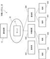
- FIG. 9 is a block diagram showing a configuration example of the relay system 1B.
- FIG. 10 is a block diagram showing the configuration of the relay device 50B described later.
- FIG. 8 is a flowchart for explaining the operation of the relay system 1B.
- the relay system 1B has the same configuration as the relay system 1 in the first embodiment.
- the relay system 1B is different from the relay system 1 in that the relay device 50B is provided in place of the relay device 50.
- the relay device 50B will be described with reference to FIG.
- the relay device 50B includes a transmission unit 51B, a reception unit 52, and a relay unit 53.
- the receiving unit 52 and the relay unit 53 have the same configurations, connection relationships, and functions as the receiving unit 52 and the relay unit 53 in the relay device 50 according to the first embodiment.
- the transmission unit 51B is different from the transmission unit 51 in the relay device 50. Specifically, the transmission unit 51 determines whether or not a failure has occurred in the base station 30A, but the transmission unit 51B does not determine whether or not a failure has occurred in the base station 30A.
- the transmission unit 51B transmits a connection request including a unique key to the terminal 40 in response to an instruction from the outside.
- the administrator of the relay system 1B grasps the occurrence of the failure in the base station 30A based on the information from the network 20. At this time, the administrator transports the relay device 50B to the vicinity of the base station 30A. The administrator instructs the transported relay device 50B to send a connection request including a unique key. As a result, a connection request is transmitted to the terminals 40A and 40B located in the vicinity of the base station 30A. As described above, in the relay system 1B, the relay device 50B transmits the connection request without determining whether or not the failure has occurred in the base station 30.
- the relay device 50B stores the unique key for each terminal 40 input from the administrator.
- this operation starts in response to an external instruction to send a connection request.
- the relay system 1B has been explained above. As described above, the relay system 1B has the same configuration as the relay system 1. Therefore, the terminal 40 in the relay system 1B may be connected to an inappropriate system that extracts the information of the terminal, guides to a malicious site, distributes erroneous information, or the like, like the terminal 40 of the relay system 1. Few.
- FIG. 12 is a block diagram showing a configuration example of the relay device 2.
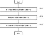
- FIG. 13 is a flowchart showing an operation example of the relay device 2.
- the relay device 2 includes a transmission unit 51, a reception unit 52, and a relay unit 53.
- the transmission unit 51 transmits a connection request including authentication information to a terminal connected to the network via the base station.
- the transmission unit 51 may have the same configuration, function, and connection relationship as the transmission unit 51 in the relay device 50 according to the first embodiment.
- the receiving unit 52 receives a notification to the effect that the connection is permitted from the terminal that has received the connection request.
- the receiving unit 52 may have the same configuration, function, and connection relationship as the receiving unit 52 in the relay device 50 according to the first embodiment.
- the relay unit 53 relays the communication between the terminal and the network.
- the relay unit 53 may have the same configuration, function, and connection relationship as the relay unit 53 in the relay device 50 according to the first embodiment.
- the transmission unit 51 transmits a connection request including authentication information to a terminal connected to the network via the base station (S201).
- the receiving unit 52 receives a notification to the effect that the connection is permitted from the terminal that has received the connection request (S202).
- the relay unit 53 When the relay unit 53 receives the notification that the connection is permitted, the relay unit 53 relays the communication between the terminal and the network (S203).
- the relay device 2 includes a transmission unit 51, a reception unit 52, and a relay unit 53.
- the transmission unit 51 transmits a connection request including authentication information to a terminal connected to the network via the base station.
- the receiving unit 52 receives a notification to the effect that the connection is permitted from the terminal that has received the connection request.
- the relay unit 53 relays the communication between the terminal and the network.
- the terminal can communicate with the network even if a failure occurs in the base station due to a disaster or the like. At this time, the terminal communicates with the network via the relay device 2 having the authentication information.
- the terminal is suppressed from communicating with the device that does not have the authentication information.
- the terminal is less likely to be connected to an inappropriate system for extracting information from the terminal, guiding to a malicious site, or distributing erroneous information.
- FIG. 14 is a block diagram showing a configuration example of the terminal 3.
- FIG. 15 is a flowchart showing an operation example of the terminal 3.
- the terminal 3 includes a connection unit 41 and a communication unit 43.
- connection unit 41 connects to the base station.
- the connection unit 41 may have the same configuration, function, and connection relationship as the connection unit 41 in the terminal 40 described in the first embodiment.
- the communication unit 43 determines whether or not the connection request received from the relay device includes the authentication information. When the connection request includes authentication information, the communication unit 43 transmits a notification to the effect that the connection is permitted to the relay device. At this time, the connection unit 41 connects to the relay device instead of the base station after the communication unit 43 transmits the notification to the relay device.
- connecting to the relay device means not only transmitting and receiving notifications to and from the relay device, but also transmitting and receiving other data as the relay device.
- the communication unit 43 may have the same configuration, function, and connection relationship as the communication unit 43 in the terminal 40 according to the first embodiment.
- connection unit 41 is connected to the base station.
- the communication unit 43 receives the connection request from the relay device (S301). Further, the communication unit 43 determines whether or not the authentication information is included in the connection request (S302).
- the terminal 3 ends the operation.
- the communication unit 43 transmits a notification to the effect that the connection is permitted (S303).
- the connection unit 41 connects to the relay device instead of the base station. The operation of the terminal 3 has been described above.
- the terminal 3 includes a connection unit 41 and a communication unit 43.
- the connection unit 41 connects to the base station.
- the communication unit 43 determines whether or not the connection request received from the relay device contains the authentication information, and if the connection request contains the authentication information, transmits a notification to the device that the connection is permitted. do. Further, the connection unit 41 connects to the relay device instead of the base station after the communication unit 43 transmits the notification to the relay device.
- the terminal 3 can communicate with the network via the relay device. Therefore, the terminal 3 can prevent communication with a device that does not have the authentication information. As a result, the terminal 3 is less likely to be connected to an inappropriate system for extracting information from the terminal 3, guiding to a malicious site, or distributing erroneous information.
Landscapes
- Engineering & Computer Science (AREA)
- Computer Security & Cryptography (AREA)
- Computer Networks & Wireless Communication (AREA)
- Signal Processing (AREA)
- Mobile Radio Communication Systems (AREA)
Priority Applications (2)
| Application Number | Priority Date | Filing Date | Title |
|---|---|---|---|
| US18/023,115 US20230328806A1 (en) | 2020-08-31 | 2021-08-30 | Relay device, terminal, and relay method |
| JP2022545755A JPWO2022045332A1 (https=) | 2020-08-31 | 2021-08-30 |
Applications Claiming Priority (2)
| Application Number | Priority Date | Filing Date | Title |
|---|---|---|---|
| JP2020145194 | 2020-08-31 | ||
| JP2020-145194 | 2020-08-31 |
Publications (1)
| Publication Number | Publication Date |
|---|---|
| WO2022045332A1 true WO2022045332A1 (ja) | 2022-03-03 |
Family
ID=80353458
Family Applications (1)
| Application Number | Title | Priority Date | Filing Date |
|---|---|---|---|
| PCT/JP2021/031696 Ceased WO2022045332A1 (ja) | 2020-08-31 | 2021-08-30 | 中継装置、端末及び中継方法 |
Country Status (3)
| Country | Link |
|---|---|
| US (1) | US20230328806A1 (https=) |
| JP (1) | JPWO2022045332A1 (https=) |
| WO (1) | WO2022045332A1 (https=) |
Families Citing this family (1)
| Publication number | Priority date | Publication date | Assignee | Title |
|---|---|---|---|---|
| JP7355073B2 (ja) * | 2021-05-19 | 2023-10-03 | トヨタ自動車株式会社 | 車両制御装置、車両、車両制御方法及びプログラム |
Citations (3)
| Publication number | Priority date | Publication date | Assignee | Title |
|---|---|---|---|---|
| JP2013021598A (ja) * | 2011-07-13 | 2013-01-31 | Sharp Corp | 通信方法、移動端末装置および基地局装置 |
| WO2018029952A1 (ja) * | 2016-08-12 | 2018-02-15 | 日本電気株式会社 | ビーム及びセキュリティ強化に関連する装置、方法、システム、プログラム及び記録媒体 |
| JP2018526869A (ja) * | 2015-07-12 | 2018-09-13 | クアルコム,インコーポレイテッド | 暗号化されたクライアントデバイスコンテキストを用いたネットワークアーキテクチャおよびセキュリティ |
Family Cites Families (3)
| Publication number | Priority date | Publication date | Assignee | Title |
|---|---|---|---|---|
| WO2018014154A1 (zh) * | 2016-07-18 | 2018-01-25 | 华为技术有限公司 | 一种rrc连接重建方法和装置 |
| EP3895400A1 (en) * | 2018-12-11 | 2021-10-20 | Sony Group Corporation | Communications device, infrastructure equipment, core network equipment and methods |
| CN113330775A (zh) * | 2019-04-30 | 2021-08-31 | Oppo广东移动通信有限公司 | 用于小区切换的方法及设备 |
-
2021
- 2021-08-30 JP JP2022545755A patent/JPWO2022045332A1/ja active Pending
- 2021-08-30 WO PCT/JP2021/031696 patent/WO2022045332A1/ja not_active Ceased
- 2021-08-30 US US18/023,115 patent/US20230328806A1/en not_active Abandoned
Patent Citations (3)
| Publication number | Priority date | Publication date | Assignee | Title |
|---|---|---|---|---|
| JP2013021598A (ja) * | 2011-07-13 | 2013-01-31 | Sharp Corp | 通信方法、移動端末装置および基地局装置 |
| JP2018526869A (ja) * | 2015-07-12 | 2018-09-13 | クアルコム,インコーポレイテッド | 暗号化されたクライアントデバイスコンテキストを用いたネットワークアーキテクチャおよびセキュリティ |
| WO2018029952A1 (ja) * | 2016-08-12 | 2018-02-15 | 日本電気株式会社 | ビーム及びセキュリティ強化に関連する装置、方法、システム、プログラム及び記録媒体 |
Also Published As
| Publication number | Publication date |
|---|---|
| JPWO2022045332A1 (https=) | 2022-03-03 |
| US20230328806A1 (en) | 2023-10-12 |
Similar Documents
| Publication | Publication Date | Title |
|---|---|---|
| US20250240285A1 (en) | Relay communication methods and apparatuses, communication device, and storage medium | |
| US7292842B2 (en) | Wireless adhoc communication system, terminal, authentication method for use in terminal, encryption method, terminal management method, and program for enabling terminal to perform those methods | |
| CN106332085B (zh) | 一种物联网wifi网络的配置方法、物联网终端和路由终端 | |
| KR101765917B1 (ko) | 개인망 엔티티 인증을 위한 방법 | |
| EP2856789B1 (en) | Method for tracking a mobile device onto a remote displaying unit via a mobile switching center and a head-end | |
| CN110073681B (zh) | 用于物联网设备的方法、装置和计算机可读介质 | |
| CN111787514B (zh) | 设备控制数据的获取方法及装置、存储介质、电子装置 | |
| JP4504970B2 (ja) | 仮想無線ローカルエリアネットワーク | |
| US9648650B2 (en) | Pairing of devices through separate networks | |
| JP4917116B2 (ja) | データ暗号化システム、通信機器、及びデータ暗号化方法 | |
| US9370031B2 (en) | Wireless network setup and configuration distribution system | |
| CN115334508B (zh) | 融合鉴权和加密的卫星短报文通信方法 | |
| JP6046782B1 (ja) | 無線通信システム、中継機、無線端末および無線通信方法 | |
| WO2022045332A1 (ja) | 中継装置、端末及び中継方法 | |
| KR101500118B1 (ko) | 데이터 공유 방법 및 이를 이용한 데이터 공유 시스템 | |
| JP2016051268A (ja) | 認証システム、認証サーバ、クライアント装置及び認証方法 | |
| CN119966630A (zh) | 密钥协商方法、装置和系统 | |
| US12425190B2 (en) | Method for protecting a network access profile against cloning | |
| EP1895784B1 (en) | A method of relaying an electronic message to a handheld electronic device beyond the coverage area of a wireless network | |
| KR20080094349A (ko) | 네트워크 접속을 위한 상태 검사 방법 및 그 단말기 | |
| US9980143B2 (en) | Communication system, base station, and terminal | |
| CN115987491B (zh) | 一种设备组的加解密算法更新方法和装置 | |
| EP4704457A1 (en) | Communication connection method and apparatus, device, and storage medium | |
| JP7183764B2 (ja) | 通信制御装置、通信制御方法及び無線通信システム | |
| JP2009118232A (ja) | 情報中継システム及び通信端末 |
Legal Events
| Date | Code | Title | Description |
|---|---|---|---|
| 121 | Ep: the epo has been informed by wipo that ep was designated in this application |
Ref document number: 21861753 Country of ref document: EP Kind code of ref document: A1 |
|
| ENP | Entry into the national phase |
Ref document number: 2022545755 Country of ref document: JP Kind code of ref document: A |
|
| NENP | Non-entry into the national phase |
Ref country code: DE |
|
| 122 | Ep: pct application non-entry in european phase |
Ref document number: 21861753 Country of ref document: EP Kind code of ref document: A1 |