WO2022045332A1 - Relay device, terminal, and relay method - Google Patents
Relay device, terminal, and relay method Download PDFInfo
- Publication number
- WO2022045332A1 WO2022045332A1 PCT/JP2021/031696 JP2021031696W WO2022045332A1 WO 2022045332 A1 WO2022045332 A1 WO 2022045332A1 JP 2021031696 W JP2021031696 W JP 2021031696W WO 2022045332 A1 WO2022045332 A1 WO 2022045332A1
- Authority
- WO
- WIPO (PCT)
- Prior art keywords
- terminal
- relay
- base station
- relay device
- notification
- Prior art date
Links
- 238000000034 method Methods 0.000 title claims description 9
- 238000004891 communication Methods 0.000 claims abstract description 46
- 230000005540 biological transmission Effects 0.000 claims abstract description 34
- 238000010586 diagram Methods 0.000 description 17
- 230000004048 modification Effects 0.000 description 10
- 238000012986 modification Methods 0.000 description 10
- 230000004044 response Effects 0.000 description 3
- 239000000284 extract Substances 0.000 description 2
- 230000008569 process Effects 0.000 description 2
- 230000032258 transport Effects 0.000 description 1
Images


Classifications
-
- H—ELECTRICITY
- H04—ELECTRIC COMMUNICATION TECHNIQUE
- H04W—WIRELESS COMMUNICATION NETWORKS
- H04W76/00—Connection management
- H04W76/10—Connection setup
-
- H—ELECTRICITY
- H04—ELECTRIC COMMUNICATION TECHNIQUE
- H04W—WIRELESS COMMUNICATION NETWORKS
- H04W12/00—Security arrangements; Authentication; Protecting privacy or anonymity
- H04W12/03—Protecting confidentiality, e.g. by encryption
- H04W12/037—Protecting confidentiality, e.g. by encryption of the control plane, e.g. signalling traffic
-
- H—ELECTRICITY
- H04—ELECTRIC COMMUNICATION TECHNIQUE
- H04W—WIRELESS COMMUNICATION NETWORKS
- H04W12/00—Security arrangements; Authentication; Protecting privacy or anonymity
- H04W12/06—Authentication
-
- H—ELECTRICITY
- H04—ELECTRIC COMMUNICATION TECHNIQUE
- H04W—WIRELESS COMMUNICATION NETWORKS
- H04W12/00—Security arrangements; Authentication; Protecting privacy or anonymity
- H04W12/08—Access security
-
- H—ELECTRICITY
- H04—ELECTRIC COMMUNICATION TECHNIQUE
- H04W—WIRELESS COMMUNICATION NETWORKS
- H04W12/00—Security arrangements; Authentication; Protecting privacy or anonymity
- H04W12/12—Detection or prevention of fraud
- H04W12/121—Wireless intrusion detection systems [WIDS]; Wireless intrusion prevention systems [WIPS]
- H04W12/122—Counter-measures against attacks; Protection against rogue devices
-
- H—ELECTRICITY
- H04—ELECTRIC COMMUNICATION TECHNIQUE
- H04W—WIRELESS COMMUNICATION NETWORKS
- H04W24/00—Supervisory, monitoring or testing arrangements
- H04W24/04—Arrangements for maintaining operational condition
-
- H—ELECTRICITY
- H04—ELECTRIC COMMUNICATION TECHNIQUE
- H04W—WIRELESS COMMUNICATION NETWORKS
- H04W76/00—Connection management
- H04W76/10—Connection setup
- H04W76/19—Connection re-establishment
-
- H—ELECTRICITY
- H04—ELECTRIC COMMUNICATION TECHNIQUE
- H04W—WIRELESS COMMUNICATION NETWORKS
- H04W76/00—Connection management
- H04W76/10—Connection setup
- H04W76/14—Direct-mode setup
-
- H—ELECTRICITY
- H04—ELECTRIC COMMUNICATION TECHNIQUE
- H04W—WIRELESS COMMUNICATION NETWORKS
- H04W88/00—Devices specially adapted for wireless communication networks, e.g. terminals, base stations or access point devices
- H04W88/02—Terminal devices
- H04W88/04—Terminal devices adapted for relaying to or from another terminal or user
Definitions
- the present invention relates to a relay device, a terminal, and a relay method that can be connected to a relay device instead of a base station.
- the Japan Meteorological Agency, etc. sends a disaster bulletin including information on the earthquake (for example, seismic intensity, epicenter, etc.) to a terminal owned by an individual via a network.
- the terminal communicates with the network via the base station corresponding to the authentication information registered in advance.
- the breaking news was not sent to the terminal.
- Patent Document 1 discloses that when the base station detects that communication is impossible, it considers that the cause of communication failure is a disaster and shifts to the disaster occurrence mode.
- Patent Document 1 does not describe the processing when a failure occurs in the base station. Further, when a failure occurs in the base station, it is conceivable to relay the communication between the terminal and the network by using the newly provided base station. However, in this case, the terminal needs to communicate with the base station that does not correspond to the authentication information in order to start the communication with the newly provided base station. At this time, the terminal may be connected to, for example, an inappropriate system for extracting information from the terminal, guiding to a malicious site, or distributing erroneous information.
- the present invention has been made in view of the above problems, and an object of the present invention is to prevent a terminal from being connected to an inappropriate system when a failure occurs in a base station.
- the relay system of the present invention is A transmission means for transmitting a connection request including authentication information to a terminal connected to a network via the base station when a failure occurs in the base station.
- a receiving means for receiving a notification to the effect that the connection is permitted from the terminal that has received the connection request, and When the receiving means notifies that the notification has been received, the relay means for relaying the communication between the terminal and the network, and the relay means. To prepare for.
- the terminal of the present invention is Connection means to connect to the base station, Communication that determines whether or not the connection request received from the relay device contains the authentication information, and if the connection request contains the authentication information, sends a notification to the relay device to the effect that the connection is permitted.
- the connecting means connects to the relay device in place of the base station after the communication means transmits the notification to the relay device.
- the relay method of the present invention is: When a failure occurs in a base station, a connection request including authentication information is sent to a terminal connected to the network via the base station. Receive a notification to the effect that the connection is permitted from the terminal that received the connection request, When the notification is received, the communication between the terminal and the network is relayed.
- FIG. 1 is a block diagram showing a configuration example of the relay system 1.
- FIG. 2 is a block diagram for explaining the details of the relay system 1.
- FIG. 3 is a block diagram showing the configuration of the terminal 40 described later.
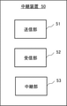
- FIG. 4 is a block diagram showing the configuration of the relay device 50 described later.
- FIG. 5 is a flowchart showing an operation example of the relay system 1.
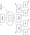
- the relay system 1 includes a notification device 10, a network 20, base stations 30A, 30B, terminals 40A, 40B, 40C, 40D, and a relay device 50.
- a notification device 10 a network 20
- base stations 30A, 30B, terminals 40A, 40B, 40C, 40D base stations 30A, 30B, 40C, 40D
- a relay device 50 a relay device 50
- each of the base stations 30A and 30B is referred to as a base station 30.
- each of the terminals 40A, 40B, 40C, and 40D is referred to as a terminal 40.
- FIG. 1 is a block diagram showing a configuration example of the relay system 1 after a failure occurs in the base station 30A due to a disaster or the like.
- FIG. 2 is a block diagram showing a configuration example of the relay system 1 before a failure occurs in the base station 30A.
- the notification device 10 can communicate with the terminal 40 via the network 20, the base station 30, and the relay device 50. For example, when a disaster occurs, the notification device 10 transmits information about the disaster to the terminal 40.
- the information about the disaster here is, for example, the area where the disaster occurred and the damage situation.
- the notification device 10 communicates with the terminals 40A and 40B via the base station 30A before the failure occurs in the base station 30A. Further, the notification device 10 communicates with the terminals 40A and 40B via the relay device 50 after a failure occurs in the base station 30A.
- the network 20 relays communication between either one of the base station 30 and the relay device 50 and the notification device 10.
- the network 20 includes at least the server 21.
- the server 21 is, for example, an HSS (Home Subscriber Server).
- the server 21 communicates with the terminal 40 and shares the unique key with the terminal 40.
- the unique key is an IMSI (International Mobile Subscriber Identity) recorded on the SIM (Subscriber Identity Module) card of the terminal 40, or an IMEI (International Mobile Equipment Identity) generated from the terminal 40's IMEI (International Mobile Equipment Identity).
- the unique key is unique to the terminal 40.
- the unique key for the terminal 40A and the unique key for the terminal 40B are different from each other.
- the unique key possessed by the terminal 40A corresponds to the authentication information.
- the base station 30 is a general base station.
- the base station 30A relays the communication between the terminal 40A and the terminal 40B and the notification device 10 via the network 20.
- the base station 30B relays the communication between the terminal 40C and the terminal 40D and the notification device 10 via the network 20.
- the terminal 40 communicates with the notification device 10 via one of the base station 30 and the relay device 50 and the network 20.
- the terminal 40 shares a unique key with the server 21.
- the terminal 40 includes a connection unit 41, an update unit 42, and a communication unit 43.
- the connection unit 41 controls the route so that the terminal 40 connects to the network 20 via the base station 30.
- the update unit 42 of the terminal 40 updates the unique key at any time. For example, the terminal 40 updates the unique key at the time of starting the terminal 40 or at a preset cycle.
- the communication unit 43 of the terminal 40 transmits the updated unique key to the server 21. At this time, the communication unit 43 transmits the unique key to the server 21 of the network 20 via the base station 30 according to the route set by the connection unit 41.
- the unique key transmitted by the communication unit 43 is transferred to the relay device 50 by the server 21. That is, the communication unit 43 transmits the unique key to the relay device 50.
- connection portion 41 of the terminals 40A and 40B connects the network 20 and the terminals 40A and 40B via the base station 30A.
- the connection portion 41 of the terminals 40A and 40B connects the network 20 and the terminals 40A and 40B via the relay device 50.
- the connection unit 41 of the terminals 40C and 40D connects the network 20 and the terminals 40C and 40D via the base station 30B.
- the relay device 50 is provided so as to be able to communicate with the server 21 at all times. As shown in FIG. 4, the relay device 50 includes a transmission unit 51, a reception unit 52, and a relay unit 53. The relay device 50 communicates with the server 21 and acquires a unique key for each terminal 40. The relay device 50 does not connect to the terminal 40 as shown in FIG. 2 until the base station 30 fails. At this time, it is assumed that the relay device 50 communicates with the server 21 and acquires the unique key. Further, the unique key may be input to the relay device 50 by the administrator of the relay system 1 when the relay device 50 is not communicating with the server 21.
- the transmission unit 51 determines that a failure has occurred in the base station 30A
- the transmission unit 51 transmits a connection request including a unique key to the terminal 40. For example, when the transmission unit 51 is notified from the outside that a failure has occurred in the base station 30A, the transmission unit 51 determines that a failure has occurred in the base station 30A.
- the terminal 40 Upon receiving the connection request, the terminal 40 transmits a notification to the relay device 50 that the connection is permitted when the unique key included in the connection request matches the unique key possessed by the terminal 40.
- the receiving unit 52 receives a notification to the effect that the connection is permitted from the terminal 40 that has received the connection request.
- the relay unit 53 connects to the terminal 40 that has transmitted the notification and relays the communication between the terminal 40 and the network.
- connection unit 41 controls the route of the terminal 40 so that the terminal 40 connects to the network 20 via the base station 30.
- the communication unit 43 of the terminal 40 transmits the unique key generated by the update unit 42 to the server 21 (S101).
- the server 21 stores the unique keys received from the plurality of terminals 40 in association with each of the terminals 40 (S102).
- the server 21 transmits the unique key for each terminal 40 to the relay device 50 at a predetermined cycle (S103). As a result, the relay device 50 acquires the unique key for each terminal 40.
- the relay device 50 determines whether or not a failure has occurred in the base station 30 (S104). If a failure occurs in the base station 30, the operation of the base station 30 is stopped. For example, the network 20 determines that a failure has occurred in the base station 30 when there is no response from the base station 30. The relay device 50 determines whether or not there is a failure in the base station 30, for example, based on the notification from the network 20.
- the relay system 1 repeats the above-mentioned processes of S101 to S103.
- the transmission unit 51 of the relay device 50 transmits a connection request including a unique key for each terminal 40 to the terminal 40 located within a predetermined range. (S105). At this time, it is assumed that the terminal 40A and the terminal 40B are located within the predetermined range.
- the relay device 50 is stored at a position away from the base station 30 before the failure occurs in the base station 30. For example, when a failure occurs in the base station 30A, the relay device 50 is carried to the vicinity of the base station 30A, for example, on a vehicle of the administrator of the relay system 1.
- the terminal 40 determines whether or not the received connection request includes the unique key possessed by the terminal 40 (S106). As a result, the terminal 40 determines whether or not the relay device 50 has the unique key generated by the terminal 40.
- the terminal 40 rejects the connection request from the relay device 50 (S107). At this time, the operation of the relay system 1 ends.
- the terminal 40 When the connection request includes the unique key possessed by the terminal 40 (Yes in S106), the terminal 40 permits the connection request from the relay device 50 (S108). At this time, the terminal 40 transmits a notification to the reception unit 52 of the relay device 50 to the effect that the connection is permitted.
- the relay unit 53 relays the communication between the terminal 40 and the network 20 (S109).
- the terminals 40A and 40B connect to the network 20 via the relay device 50 instead of the base station 30A, and acquire information about the disaster from the notification device 10.
- the receiving unit 52 that has received the notification that the connection is permitted notifies the relay unit 53 that the notification has been received.
- the relay unit 53 determines that the reception unit 52 has received the notification that the connection is permitted. The operation of the relay system 1 has been described above.
- the relay device 50 of the relay system 1 includes a transmission unit 51, a reception unit 52, and a relay unit 53.
- the transmission unit 51 transmits a connection request including authentication information (unique key) to the terminal 40 connected to the network 20 via the base station 30.
- the receiving unit 52 receives a notification from the terminal 40 that has received the connection request to the effect that the connection is permitted.
- the relay unit 53 relays the communication between the terminal 40 and the network 20.
- the terminal 40 can communicate with the network 20.
- the terminal 40 communicates with the network 20 via the relay device 50 that stores common information (authentication information). Therefore, the terminal 40 of the relay system 1 can prevent communication with a device that does not have the authentication information. As a result, the terminal 40 is less likely to be connected to an inappropriate system for extracting information from the terminal, guiding to a malicious site, or distributing erroneous information.
- FIG. 6 is a block diagram showing a configuration example of the relay system 1A.
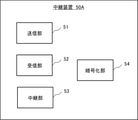
- FIG. 7 is a block diagram showing the configuration of the relay device 50A described later.
- FIG. 8 is a flowchart for explaining the operation of the relay system 1A.
- the relay system 1A has the same configuration as the relay system 1 in the first embodiment.
- the relay system 1A differs from the relay system 1 in that the relay device 50A is provided in place of the relay device 50.
- the relay device 50A has a connection relationship, a configuration, and a function included in the relay device 50.
- the relay device 50A includes a transmission unit 51, a reception unit 52, and a relay unit 53.
- the relay device 50A further includes an encryption unit 54 and a transmission unit 55.
- the transmission unit 55 transmits the shared key to the terminal 40 that has permitted the connection request.
- the shared key indicates an encryption method used for data encryption and decryption.
- the notification device 54 receives the notification of information about the disaster
- the encryption unit 54 of the relay device 50A encrypts the received notification using the shared key.
- the transmission unit 55 transmits the encrypted notification to the terminal 40.
- the terminal 40 having the shared key decrypts the encrypted notification by using the shared key.
- the relay system 1A performs the operation shown in FIG. 5 in the same manner as the relay system 1 described above.
- the operation of the relay system 1A shown in FIG. 8 shall be performed after the processing of S109.
- the transmission unit 51 of the relay device 50A After starting the relay of the communication between the terminal 40 and the network 20 in the process of S109, the transmission unit 51 of the relay device 50A further transmits the shared key to the terminal 40 that has permitted the connection request (S110).
- the encryption unit 54 of the relay device 50 encrypts the notification received from the notification device 10 by an encryption method according to the shared key (S111).
- the transmission unit 51 transmits the encrypted information to the terminal 40 that has permitted the connection request (S112).
- the terminal 40 receives the encrypted information and decodes it by a decryption method according to the shared key (S113). At this time, the terminal 40 displays the decoded information to the user of the terminal 40 via the display of the terminal 40 or the like.
- the operation of the relay system 1A has been described above.
- the relay system 1A has the same configuration as the relay system 1. Therefore, the terminal 40 in the relay system 1A may be connected to an inappropriate system that extracts the information of the terminal, guides the user to a malicious site, distributes erroneous information, or the like, like the terminal 40 of the relay system 1. Few.
- the encryption unit 54 encrypts the information from the network 20. Further, the transmission unit 51 transmits the encrypted information to the terminal 40.
- the information received from the network is encrypted according to the common key. Therefore, even if the information transmitted from the relay device 50 to the terminal 40 is intercepted by another person, the intercepted information is encrypted, so that the other person cannot grasp the content of the information. Therefore, in the relay system 1A, the confidentiality of the information transmitted from the relay device 50 to the terminal 40 is ensured.
- FIG. 9 is a block diagram showing a configuration example of the relay system 1B.
- FIG. 10 is a block diagram showing the configuration of the relay device 50B described later.
- FIG. 8 is a flowchart for explaining the operation of the relay system 1B.
- the relay system 1B has the same configuration as the relay system 1 in the first embodiment.
- the relay system 1B is different from the relay system 1 in that the relay device 50B is provided in place of the relay device 50.
- the relay device 50B will be described with reference to FIG.
- the relay device 50B includes a transmission unit 51B, a reception unit 52, and a relay unit 53.
- the receiving unit 52 and the relay unit 53 have the same configurations, connection relationships, and functions as the receiving unit 52 and the relay unit 53 in the relay device 50 according to the first embodiment.
- the transmission unit 51B is different from the transmission unit 51 in the relay device 50. Specifically, the transmission unit 51 determines whether or not a failure has occurred in the base station 30A, but the transmission unit 51B does not determine whether or not a failure has occurred in the base station 30A.
- the transmission unit 51B transmits a connection request including a unique key to the terminal 40 in response to an instruction from the outside.
- the administrator of the relay system 1B grasps the occurrence of the failure in the base station 30A based on the information from the network 20. At this time, the administrator transports the relay device 50B to the vicinity of the base station 30A. The administrator instructs the transported relay device 50B to send a connection request including a unique key. As a result, a connection request is transmitted to the terminals 40A and 40B located in the vicinity of the base station 30A. As described above, in the relay system 1B, the relay device 50B transmits the connection request without determining whether or not the failure has occurred in the base station 30.
- the relay device 50B stores the unique key for each terminal 40 input from the administrator.
- this operation starts in response to an external instruction to send a connection request.
- the relay system 1B has been explained above. As described above, the relay system 1B has the same configuration as the relay system 1. Therefore, the terminal 40 in the relay system 1B may be connected to an inappropriate system that extracts the information of the terminal, guides to a malicious site, distributes erroneous information, or the like, like the terminal 40 of the relay system 1. Few.
- FIG. 12 is a block diagram showing a configuration example of the relay device 2.
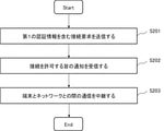
- FIG. 13 is a flowchart showing an operation example of the relay device 2.
- the relay device 2 includes a transmission unit 51, a reception unit 52, and a relay unit 53.
- the transmission unit 51 transmits a connection request including authentication information to a terminal connected to the network via the base station.
- the transmission unit 51 may have the same configuration, function, and connection relationship as the transmission unit 51 in the relay device 50 according to the first embodiment.
- the receiving unit 52 receives a notification to the effect that the connection is permitted from the terminal that has received the connection request.
- the receiving unit 52 may have the same configuration, function, and connection relationship as the receiving unit 52 in the relay device 50 according to the first embodiment.
- the relay unit 53 relays the communication between the terminal and the network.
- the relay unit 53 may have the same configuration, function, and connection relationship as the relay unit 53 in the relay device 50 according to the first embodiment.
- the transmission unit 51 transmits a connection request including authentication information to a terminal connected to the network via the base station (S201).
- the receiving unit 52 receives a notification to the effect that the connection is permitted from the terminal that has received the connection request (S202).
- the relay unit 53 When the relay unit 53 receives the notification that the connection is permitted, the relay unit 53 relays the communication between the terminal and the network (S203).
- the relay device 2 includes a transmission unit 51, a reception unit 52, and a relay unit 53.
- the transmission unit 51 transmits a connection request including authentication information to a terminal connected to the network via the base station.
- the receiving unit 52 receives a notification to the effect that the connection is permitted from the terminal that has received the connection request.
- the relay unit 53 relays the communication between the terminal and the network.
- the terminal can communicate with the network even if a failure occurs in the base station due to a disaster or the like. At this time, the terminal communicates with the network via the relay device 2 having the authentication information.
- the terminal is suppressed from communicating with the device that does not have the authentication information.
- the terminal is less likely to be connected to an inappropriate system for extracting information from the terminal, guiding to a malicious site, or distributing erroneous information.
- FIG. 14 is a block diagram showing a configuration example of the terminal 3.
- FIG. 15 is a flowchart showing an operation example of the terminal 3.
- the terminal 3 includes a connection unit 41 and a communication unit 43.
- connection unit 41 connects to the base station.
- the connection unit 41 may have the same configuration, function, and connection relationship as the connection unit 41 in the terminal 40 described in the first embodiment.
- the communication unit 43 determines whether or not the connection request received from the relay device includes the authentication information. When the connection request includes authentication information, the communication unit 43 transmits a notification to the effect that the connection is permitted to the relay device. At this time, the connection unit 41 connects to the relay device instead of the base station after the communication unit 43 transmits the notification to the relay device.
- connecting to the relay device means not only transmitting and receiving notifications to and from the relay device, but also transmitting and receiving other data as the relay device.
- the communication unit 43 may have the same configuration, function, and connection relationship as the communication unit 43 in the terminal 40 according to the first embodiment.
- connection unit 41 is connected to the base station.
- the communication unit 43 receives the connection request from the relay device (S301). Further, the communication unit 43 determines whether or not the authentication information is included in the connection request (S302).
- the terminal 3 ends the operation.
- the communication unit 43 transmits a notification to the effect that the connection is permitted (S303).
- the connection unit 41 connects to the relay device instead of the base station. The operation of the terminal 3 has been described above.
- the terminal 3 includes a connection unit 41 and a communication unit 43.
- the connection unit 41 connects to the base station.
- the communication unit 43 determines whether or not the connection request received from the relay device contains the authentication information, and if the connection request contains the authentication information, transmits a notification to the device that the connection is permitted. do. Further, the connection unit 41 connects to the relay device instead of the base station after the communication unit 43 transmits the notification to the relay device.
- the terminal 3 can communicate with the network via the relay device. Therefore, the terminal 3 can prevent communication with a device that does not have the authentication information. As a result, the terminal 3 is less likely to be connected to an inappropriate system for extracting information from the terminal 3, guiding to a malicious site, or distributing erroneous information.
Abstract
In order to suppress a terminal from being connected to an inappropriate system when failures occur in a base station, this relay device comprises: a transmission means that, when failures occur in a base station, transmits a connection request including authentication information to a terminal connected to a network via the base station; a reception means that receives, from the terminal that has received the connection request, a notification indicating that connection is permitted; and a relay means that, upon being notified by the reception means that the notification has been received, relays communication between the terminal and the network.
Description
本発明は、基地局に代えて中継装置と接続可能な中継装置、端末及び中継方法に関する。
The present invention relates to a relay device, a terminal, and a relay method that can be connected to a relay device instead of a base station.
地震などの災害が発生した場合、気象庁等は、地震に関する情報(例えば、震度や震源地など)を含む災害速報を、ネットワークを介して個人が所有する端末に送信する。この際、端末は、予め登録された認証情報に対応する基地局を介して、ネットワークと通信する。しかし、地震などの災害によって基地局の倒壊等が生じた場合、災害速報は、端末まで送信されなかった。
When a disaster such as an earthquake occurs, the Japan Meteorological Agency, etc. sends a disaster bulletin including information on the earthquake (for example, seismic intensity, epicenter, etc.) to a terminal owned by an individual via a network. At this time, the terminal communicates with the network via the base station corresponding to the authentication information registered in advance. However, when a base station collapsed due to a disaster such as an earthquake, the breaking news was not sent to the terminal.
また、特許文献1には、基地局は、通信が不能であることを検出した場合に通信不能の原因が災害であるとみなし、災害発生モードに移行することが開示されている。
Further, Patent Document 1 discloses that when the base station detects that communication is impossible, it considers that the cause of communication failure is a disaster and shifts to the disaster occurrence mode.
しかし、特許文献1には、基地局に障害が発生した場合の処理については記載されていない。また、基地局に障害が発生した場合は、新たに設けられた基地局を用いて、端末とネットワーク間の通信を中継することが考えられる。しかし、この場合、端末は、新たに設けられる基地局との通信を開始するために、認証情報に対応しない基地局と通信をする必要がある。この際、端末は、例えば、端末の情報の抜き取り、悪意のあるサイトへの誘導又は誤情報の配信等を行う不適切なシステムと接続されるおそれがある。
However, Patent Document 1 does not describe the processing when a failure occurs in the base station. Further, when a failure occurs in the base station, it is conceivable to relay the communication between the terminal and the network by using the newly provided base station. However, in this case, the terminal needs to communicate with the base station that does not correspond to the authentication information in order to start the communication with the newly provided base station. At this time, the terminal may be connected to, for example, an inappropriate system for extracting information from the terminal, guiding to a malicious site, or distributing erroneous information.
本発明は、上記問題に鑑みてなされたものであり、本発明は、基地局で障害が発生した場合に、端末が不適切なシステムに接続されることを抑制することを目的とする。
The present invention has been made in view of the above problems, and an object of the present invention is to prevent a terminal from being connected to an inappropriate system when a failure occurs in a base station.
本発明の中継システムは、
基地局で障害が生じた場合に、前記基地局を介してネットワークに接続していた端末に認証情報を含む接続要求を送信する送信手段と、
前記接続要求を受信した前記端末から接続を許可する旨の通知を受信する受信手段と、
前記受信手段から前記通知を受信した旨が通知された場合、前記端末と前記ネットワークとの間の通信を中継する中継手段と、
を備える。 The relay system of the present invention is
A transmission means for transmitting a connection request including authentication information to a terminal connected to a network via the base station when a failure occurs in the base station.
A receiving means for receiving a notification to the effect that the connection is permitted from the terminal that has received the connection request, and
When the receiving means notifies that the notification has been received, the relay means for relaying the communication between the terminal and the network, and the relay means.
To prepare for.
また、本発明の端末は、
基地局と接続する接続手段と、
中継装置から受信した接続要求に認証情報が含まれているかどうかを判断し、前記接続要求に前記認証情報が含まれている場合に、接続を許可する旨の通知を前記中継装置に送信する通信手段と、を備え、
前記接続手段は、前記通信手段が前記通知を前記中継装置に送信した後、前記基地局に代えて前記中継装置と接続する。 Further, the terminal of the present invention is
Connection means to connect to the base station,
Communication that determines whether or not the connection request received from the relay device contains the authentication information, and if the connection request contains the authentication information, sends a notification to the relay device to the effect that the connection is permitted. With means,
The connecting means connects to the relay device in place of the base station after the communication means transmits the notification to the relay device.
また、本発明の中継方法は、
基地局で障害が生じた場合に、前記基地局を介してネットワークに接続していた端末に認証情報を含む接続要求を送信し、
前記接続要求を受信した前記端末から接続を許可する旨の通知を受信し、
前記通知を受信した場合、前記端末と前記ネットワークとの間の通信を中継する。 Further, the relay method of the present invention is:
When a failure occurs in a base station, a connection request including authentication information is sent to a terminal connected to the network via the base station.
Receive a notification to the effect that the connection is permitted from the terminal that received the connection request,
When the notification is received, the communication between the terminal and the network is relayed.
本発明によれば、基地局で障害が発生した場合に、端末が不適切なシステムに接続されることを抑制することが可能である。
According to the present invention, it is possible to prevent a terminal from being connected to an inappropriate system when a failure occurs in a base station.
<第1の実施形態>
第1の実施形態における中継システム1について、図1、図2、図3、図4及び図5を用いて説明する。図1は、中継システム1の構成例を示すブロック図である。図2は、中継システム1の詳細を説明するためのブロック図である。図3は、後述の端末40の構成を示すブロック図である。図4は、後述の中継装置50の構成を示すブロック図である。図5は、中継システム1の動作例を示すフローチャートである。 <First Embodiment>
The relay system 1 in the first embodiment will be described with reference to FIGS. 1, 2, 3, 4, and 5. FIG. 1 is a block diagram showing a configuration example of the relay system 1. FIG. 2 is a block diagram for explaining the details of the relay system 1. FIG. 3 is a block diagram showing the configuration of the terminal 40 described later. FIG. 4 is a block diagram showing the configuration of therelay device 50 described later. FIG. 5 is a flowchart showing an operation example of the relay system 1.
第1の実施形態における中継システム1について、図1、図2、図3、図4及び図5を用いて説明する。図1は、中継システム1の構成例を示すブロック図である。図2は、中継システム1の詳細を説明するためのブロック図である。図3は、後述の端末40の構成を示すブロック図である。図4は、後述の中継装置50の構成を示すブロック図である。図5は、中継システム1の動作例を示すフローチャートである。 <First Embodiment>
The relay system 1 in the first embodiment will be described with reference to FIGS. 1, 2, 3, 4, and 5. FIG. 1 is a block diagram showing a configuration example of the relay system 1. FIG. 2 is a block diagram for explaining the details of the relay system 1. FIG. 3 is a block diagram showing the configuration of the terminal 40 described later. FIG. 4 is a block diagram showing the configuration of the
中継システム1の構成について説明する。図1に示されるように、中継システム1は、通知装置10、ネットワーク20、基地局30A、30B、端末40A,40B、40C、40D及び中継装置50を備える。なお、後述の説明において、基地局30A、30Bの各々を区別する必要がない場合、基地局30A、30Bの各々を基地局30と称する。また、端末40A,40B、40C、40Dの各々を区別する必要がない場合、端末40A,40B、40C、40Dの各々を端末40と称する。
The configuration of the relay system 1 will be explained. As shown in FIG. 1, the relay system 1 includes a notification device 10, a network 20, base stations 30A, 30B, terminals 40A, 40B, 40C, 40D, and a relay device 50. In the description below, when it is not necessary to distinguish between the base stations 30A and 30B, each of the base stations 30A and 30B is referred to as a base station 30. When it is not necessary to distinguish each of the terminals 40A, 40B, 40C, and 40D, each of the terminals 40A, 40B, 40C, and 40D is referred to as a terminal 40.
また、図1は、災害などによって、基地局30Aに障害が発生した後の中継システム1の構成例を示すブロック図である。また、図2は、基地局30Aに障害が発生する前の中継システム1の構成例を示すブロック図である。
Further, FIG. 1 is a block diagram showing a configuration example of the relay system 1 after a failure occurs in the base station 30A due to a disaster or the like. Further, FIG. 2 is a block diagram showing a configuration example of the relay system 1 before a failure occurs in the base station 30A.
通知装置10は、ネットワーク20、基地局30及び中継装置50を介して、端末40と通信可能である。例えば、通知装置10は、災害が発生した際に、災害に関する情報を端末40に送信する。ここでの災害に関する情報とは、例えば、災害の発生地域や被害状況などである。
The notification device 10 can communicate with the terminal 40 via the network 20, the base station 30, and the relay device 50. For example, when a disaster occurs, the notification device 10 transmits information about the disaster to the terminal 40. The information about the disaster here is, for example, the area where the disaster occurred and the damage situation.
図1及び図2に示されるように、通知装置10は、基地局30Aに障害が発生する前において、基地局30Aを介して端末40A、40Bと通信する。また、通知装置10は、基地局30Aに障害が発生した後において、中継装置50を介して端末40A、40Bと通信する。
As shown in FIGS. 1 and 2, the notification device 10 communicates with the terminals 40A and 40B via the base station 30A before the failure occurs in the base station 30A. Further, the notification device 10 communicates with the terminals 40A and 40B via the relay device 50 after a failure occurs in the base station 30A.
ネットワーク20は、基地局30及び中継装置50の何れか一方と通知装置10との間の通信を中継する。ネットワーク20は、少なくともサーバ21を含む。サーバ21は、例えば、HSS(Home Subscriber Server)である。サーバ21は、端末40と通信し、固有鍵を端末40と共有している。固有鍵とは、端末40のSIM(Subscriber Identity Module)カードに記録されたIMSI(International Mobile Subscriber Identity)や、端末40のIMEI(International Mobile Equipment Identifier)から生成されたものである。固有鍵は、端末40に対して固有のものである。例えば、端末40Aに対する固有鍵と、端末40Bに対する固有鍵は互いに異なる。端末40Aが有する固有鍵は、認証情報に対応する。
The network 20 relays communication between either one of the base station 30 and the relay device 50 and the notification device 10. The network 20 includes at least the server 21. The server 21 is, for example, an HSS (Home Subscriber Server). The server 21 communicates with the terminal 40 and shares the unique key with the terminal 40. The unique key is an IMSI (International Mobile Subscriber Identity) recorded on the SIM (Subscriber Identity Module) card of the terminal 40, or an IMEI (International Mobile Equipment Identity) generated from the terminal 40's IMEI (International Mobile Equipment Identity). The unique key is unique to the terminal 40. For example, the unique key for the terminal 40A and the unique key for the terminal 40B are different from each other. The unique key possessed by the terminal 40A corresponds to the authentication information.
基地局30は、一般的な基地局である。基地局30Aは、端末40A及び端末40Bと通知装置10との通信を、ネットワーク20を介して中継する。基地局30Bは、端末40C及び端末40Dと通知装置10との通信を、ネットワーク20を介して中継する。
The base station 30 is a general base station. The base station 30A relays the communication between the terminal 40A and the terminal 40B and the notification device 10 via the network 20. The base station 30B relays the communication between the terminal 40C and the terminal 40D and the notification device 10 via the network 20.
端末40は、基地局30及び中継装置50の一方と、ネットワーク20とを介して通知装置10と通信する。端末40は、サーバ21と固有鍵を共有している。端末40は、図3に示されるように、接続部41、更新部42及び通信部43を備える。接続部41は、端末40が、基地局30を介してネットワーク20と接続するように経路制御を行う。端末40の更新部42は、固有鍵を随時更新する。例えば、端末40は、端末40の起動時や、予め設定された周期で、固有鍵を更新する。端末40の通信部43は、更新した固有鍵を、サーバ21に送信する。この際、通信部43は、接続部41が設定した経路にしたがって、基地局30を介して、ネットワーク20のサーバ21に固有鍵を送信する。通信部43が送信した固有鍵は、サーバ21により、中継装置50に転送される。すなわち、通信部43は、中継装置50に対して、固有鍵を送信している。
The terminal 40 communicates with the notification device 10 via one of the base station 30 and the relay device 50 and the network 20. The terminal 40 shares a unique key with the server 21. As shown in FIG. 3, the terminal 40 includes a connection unit 41, an update unit 42, and a communication unit 43. The connection unit 41 controls the route so that the terminal 40 connects to the network 20 via the base station 30. The update unit 42 of the terminal 40 updates the unique key at any time. For example, the terminal 40 updates the unique key at the time of starting the terminal 40 or at a preset cycle. The communication unit 43 of the terminal 40 transmits the updated unique key to the server 21. At this time, the communication unit 43 transmits the unique key to the server 21 of the network 20 via the base station 30 according to the route set by the connection unit 41. The unique key transmitted by the communication unit 43 is transferred to the relay device 50 by the server 21. That is, the communication unit 43 transmits the unique key to the relay device 50.
基地局30Aに障害が生じるまでは、図2に示されるように、端末40A及び40Bの接続部41は、基地局30Aを介して、ネットワーク20と端末40A及び40Bを接続する。基地局30Aに障害が生じた後は、図1に示されるように、端末40A及び40Bの接続部41は、中継装置50を介して、ネットワーク20と端末40A及び40Bを接続する。また、端末40C及び40Dの接続部41は、基地局30Bを介して、ネットワーク20と端末40C及び40Dを接続する。
Until a failure occurs in the base station 30A, as shown in FIG. 2, the connection portion 41 of the terminals 40A and 40B connects the network 20 and the terminals 40A and 40B via the base station 30A. After the failure occurs in the base station 30A, as shown in FIG. 1, the connection portion 41 of the terminals 40A and 40B connects the network 20 and the terminals 40A and 40B via the relay device 50. Further, the connection unit 41 of the terminals 40C and 40D connects the network 20 and the terminals 40C and 40D via the base station 30B.
中継装置50は、常時、サーバ21と通信可能なように設けられている。中継装置50は、図4に示されるように、送信部51、受信部52及び中継部53を備える。中継装置50は、サーバ21と通信し、端末40毎の固有鍵を取得する。中継装置50は、基地局30に障害が生じるまでは、図2に示されるように端末40と接続しない。この際、中継装置50は、サーバ21と通信し、固有鍵を取得しているものとする。また、固有鍵は、中継装置50がサーバ21と通信していない場合、中継システム1の管理者によって、中継装置50に入力されても良い。
The relay device 50 is provided so as to be able to communicate with the server 21 at all times. As shown in FIG. 4, the relay device 50 includes a transmission unit 51, a reception unit 52, and a relay unit 53. The relay device 50 communicates with the server 21 and acquires a unique key for each terminal 40. The relay device 50 does not connect to the terminal 40 as shown in FIG. 2 until the base station 30 fails. At this time, it is assumed that the relay device 50 communicates with the server 21 and acquires the unique key. Further, the unique key may be input to the relay device 50 by the administrator of the relay system 1 when the relay device 50 is not communicating with the server 21.
送信部51は、基地局30Aで障害が発生したと判断した場合、端末40に対して、固有鍵を含む接続要求を送信する。例えば、送信部51は、外部から基地局30Aにおける障害の発生が通知された場合に、基地局30Aで障害が発生したと判断する。接続要求を受信した端末40は、接続要求に含まれている固有鍵が、自身の有する固有鍵と一致した場合に、接続を許可する旨の通知を中継装置50に送信する。
When the transmission unit 51 determines that a failure has occurred in the base station 30A, the transmission unit 51 transmits a connection request including a unique key to the terminal 40. For example, when the transmission unit 51 is notified from the outside that a failure has occurred in the base station 30A, the transmission unit 51 determines that a failure has occurred in the base station 30A. Upon receiving the connection request, the terminal 40 transmits a notification to the relay device 50 that the connection is permitted when the unique key included in the connection request matches the unique key possessed by the terminal 40.
受信部52は、接続要求を受信した端末40から接続を許可する旨の通知を受信する。受信部52が当該通知を受信した場合、中継部53は、当該通知を送信した端末40と接続し、端末40とネットワークとの間の通信を中継する。
The receiving unit 52 receives a notification to the effect that the connection is permitted from the terminal 40 that has received the connection request. When the receiving unit 52 receives the notification, the relay unit 53 connects to the terminal 40 that has transmitted the notification and relays the communication between the terminal 40 and the network.
以上、中継システム1の構成について説明した。次に、図5を用いて中継システム1の動作例を説明する。なお、この動作例の開始時点において、接続部41は、端末40が基地局30を介してネットワーク20に接続するように、端末40の経路制御をしているものとする。
The configuration of the relay system 1 has been explained above. Next, an operation example of the relay system 1 will be described with reference to FIG. At the start of this operation example, it is assumed that the connection unit 41 controls the route of the terminal 40 so that the terminal 40 connects to the network 20 via the base station 30.
端末40の通信部43は、更新部42により生成された固有鍵を、サーバ21へ送信する(S101)。
The communication unit 43 of the terminal 40 transmits the unique key generated by the update unit 42 to the server 21 (S101).
サーバ21は、複数の端末40から受信した固有鍵を、端末40の各々に対応付けて記憶する(S102)。
The server 21 stores the unique keys received from the plurality of terminals 40 in association with each of the terminals 40 (S102).
サーバ21は、中継装置50に対して、所定の周期で端末40毎の固有鍵を送信する(S103)。これにより、中継装置50は、端末40毎の固有鍵を取得する。
The server 21 transmits the unique key for each terminal 40 to the relay device 50 at a predetermined cycle (S103). As a result, the relay device 50 acquires the unique key for each terminal 40.
中継装置50は、基地局30で障害が発生したかどうかを判断する(S104)。基地局30で障害が発生した場合、基地局30の動作が停止する。例えば、ネットワーク20は、基地局30からの応答がない場合に、基地局30で障害が発生したと判断する。中継装置50は、例えば、ネットワーク20からの通知に基づいて、基地局30での障害の有無を判断する。
The relay device 50 determines whether or not a failure has occurred in the base station 30 (S104). If a failure occurs in the base station 30, the operation of the base station 30 is stopped. For example, the network 20 determines that a failure has occurred in the base station 30 when there is no response from the base station 30. The relay device 50 determines whether or not there is a failure in the base station 30, for example, based on the notification from the network 20.
基地局30で障害が発生していない場合(S104のNo)、中継システム1は、前述のS101~S103の処理を繰り返す。
If no failure has occurred in the base station 30 (No in S104), the relay system 1 repeats the above-mentioned processes of S101 to S103.
基地局30で障害が発生した場合(S104のYes)、中継装置50の送信部51は、所定の範囲内に位置する端末40に向けて、端末40毎の固有鍵を含む接続要求を送信する(S105)。この際、所定の範囲内には、端末40A及び端末40Bが位置していたとする。基地局30が設けられている地域において災害が発生した場合、基地局30の近傍に中継装置50を配置していると、基地局30での障害だけでなく、中継装置50での障害も生じてしまう。このため、中継装置50は、基地局30での障害の発生前において、基地局30から離れた位置で保管されている。例えば、基地局30Aにおいて障害が発生した場合、中継装置50は、例えば中継システム1の管理者の車両などに乗せられて、基地局30Aの付近まで運ばれる。
When a failure occurs in the base station 30 (Yes in S104), the transmission unit 51 of the relay device 50 transmits a connection request including a unique key for each terminal 40 to the terminal 40 located within a predetermined range. (S105). At this time, it is assumed that the terminal 40A and the terminal 40B are located within the predetermined range. When a disaster occurs in an area where the base station 30 is provided, if the relay device 50 is arranged in the vicinity of the base station 30, not only a failure in the base station 30 but also a failure in the relay device 50 occurs. Will end up. Therefore, the relay device 50 is stored at a position away from the base station 30 before the failure occurs in the base station 30. For example, when a failure occurs in the base station 30A, the relay device 50 is carried to the vicinity of the base station 30A, for example, on a vehicle of the administrator of the relay system 1.
端末40は、受信した接続要求に、当該端末40が有する固有鍵が含まれているかどうかを判断する(S106)。これにより、端末40は、当該端末40が生成した固有鍵を、中継装置50が有するかどうかを判断する。
The terminal 40 determines whether or not the received connection request includes the unique key possessed by the terminal 40 (S106). As a result, the terminal 40 determines whether or not the relay device 50 has the unique key generated by the terminal 40.
接続要求に端末40が有する固有鍵が含まれていない場合(S106のNo)、端末40は、中継装置50からの接続要求を拒否する(S107)。この際、中継システム1の動作は終了する。
When the connection request does not include the unique key possessed by the terminal 40 (No in S106), the terminal 40 rejects the connection request from the relay device 50 (S107). At this time, the operation of the relay system 1 ends.
接続要求に端末40が有する固有鍵が含まれている場合(S106のYes)、端末40は、中継装置50からの接続要求を許可する(S108)。この際、端末40は、中継装置50の受信部52に対して、接続を許可する旨の通知を送信する。
When the connection request includes the unique key possessed by the terminal 40 (Yes in S106), the terminal 40 permits the connection request from the relay device 50 (S108). At this time, the terminal 40 transmits a notification to the reception unit 52 of the relay device 50 to the effect that the connection is permitted.
接続を許可する旨の通知を受信部52が受信した場合、中継部53は、端末40とネットワーク20との間の通信を中継する(S109)。これにより、例えば端末40A及び40Bは、基地局30Aに代えて、中継装置50を介して、ネットワーク20と接続し、通知装置10から災害に関する情報を取得する。なお、接続を許可する旨の通知を受信した受信部52は、中継部53に、通知を受けた旨を通知する。当該通知を検出した際に、中継部53は、受信部52が接続を許可する旨の通知を受信したと判断する。以上、中継システム1の動作について説明した。
When the receiving unit 52 receives the notification that the connection is permitted, the relay unit 53 relays the communication between the terminal 40 and the network 20 (S109). As a result, for example, the terminals 40A and 40B connect to the network 20 via the relay device 50 instead of the base station 30A, and acquire information about the disaster from the notification device 10. The receiving unit 52 that has received the notification that the connection is permitted notifies the relay unit 53 that the notification has been received. When the notification is detected, the relay unit 53 determines that the reception unit 52 has received the notification that the connection is permitted. The operation of the relay system 1 has been described above.
以上のように、中継システム1の中継装置50は、送信部51、受信部52、中継部53を備える。送信部51は、基地局30で障害が生じた場合に、基地局30を介してネットワーク20に接続していた端末40に認証情報(固有鍵)を含む接続要求を送信する。受信部52は、接続要求を受信した端末40から接続を許可する旨の通知を受信する。中継部53は、接続を許可する旨の通知を受信した場合、端末40とネットワーク20との間の通信を中継する。
As described above, the relay device 50 of the relay system 1 includes a transmission unit 51, a reception unit 52, and a relay unit 53. When a failure occurs in the base station 30, the transmission unit 51 transmits a connection request including authentication information (unique key) to the terminal 40 connected to the network 20 via the base station 30. The receiving unit 52 receives a notification from the terminal 40 that has received the connection request to the effect that the connection is permitted. When the relay unit 53 receives the notification that the connection is permitted, the relay unit 53 relays the communication between the terminal 40 and the network 20.
これにより、災害などによって基地局30に障害が発生した場合であっても、端末40は、ネットワーク20と通信することができる。この際、端末40は、共通の情報(認証情報)を記憶する中継装置50を介して、ネットワーク20と通信する。そのため、中継システム1の端末40は、認証情報を有しない装置との通信を防ぐことができる。この結果、端末40は、端末の情報の抜き取り、悪意のあるサイトへの誘導又は誤情報の配信等を行う不適切なシステムと接続されるおそれが少ない。
Thereby, even if a failure occurs in the base station 30 due to a disaster or the like, the terminal 40 can communicate with the network 20. At this time, the terminal 40 communicates with the network 20 via the relay device 50 that stores common information (authentication information). Therefore, the terminal 40 of the relay system 1 can prevent communication with a device that does not have the authentication information. As a result, the terminal 40 is less likely to be connected to an inappropriate system for extracting information from the terminal, guiding to a malicious site, or distributing erroneous information.
<第1の変形例>
次に、第1の実施形態の第1の変形例における中継システム1Aについて、図6、図7及び図8を用いて説明する。図6は、中継システム1Aの構成例を示すブロック図である。図7は、後述の中継装置50Aの構成を示すブロック図である。図8は、中継システム1Aの動作を示す説明するためのフローチャートである。 <First modification>
Next, the relay system 1A in the first modification of the first embodiment will be described with reference to FIGS. 6, 7, and 8. FIG. 6 is a block diagram showing a configuration example of the relay system 1A. FIG. 7 is a block diagram showing the configuration of therelay device 50A described later. FIG. 8 is a flowchart for explaining the operation of the relay system 1A.
次に、第1の実施形態の第1の変形例における中継システム1Aについて、図6、図7及び図8を用いて説明する。図6は、中継システム1Aの構成例を示すブロック図である。図7は、後述の中継装置50Aの構成を示すブロック図である。図8は、中継システム1Aの動作を示す説明するためのフローチャートである。 <First modification>
Next, the relay system 1A in the first modification of the first embodiment will be described with reference to FIGS. 6, 7, and 8. FIG. 6 is a block diagram showing a configuration example of the relay system 1A. FIG. 7 is a block diagram showing the configuration of the
図6に示されるように、中継システム1Aは、第1の実施形態における中継システム1と同様の構成を備える。中継システム1Aは、中継装置50に代えて中継装置50Aを備えている点において、中継システム1と異なる。
As shown in FIG. 6, the relay system 1A has the same configuration as the relay system 1 in the first embodiment. The relay system 1A differs from the relay system 1 in that the relay device 50A is provided in place of the relay device 50.
図7を用いて、中継装置50Aについて説明する。中継装置50Aは、中継装置50が備える接続関係、構成及び機能を備える。具体的には、中継装置50Aは、送信部51、受信部52及び中継部53を備える。中継装置50Aは、更に、暗号化部54及び送信部55を備える。送信部55は、接続要求を許可した端末40に対して、共有鍵を送信する。共有鍵は、データの暗号化及び復号に用いられる暗号方式を示すものである。中継装置50Aの暗号化部54は、通知装置10から災害に関する情報の通知を受信したとき、当該共有鍵を用いて受信した通知を暗号化する。そして、送信部55は、暗号化した通知を端末40に送信する。共有鍵を有する端末40は、共有鍵を用いて、暗号化された通知を復号する。
The relay device 50A will be described with reference to FIG. 7. The relay device 50A has a connection relationship, a configuration, and a function included in the relay device 50. Specifically, the relay device 50A includes a transmission unit 51, a reception unit 52, and a relay unit 53. The relay device 50A further includes an encryption unit 54 and a transmission unit 55. The transmission unit 55 transmits the shared key to the terminal 40 that has permitted the connection request. The shared key indicates an encryption method used for data encryption and decryption. When the notification device 54 receives the notification of information about the disaster, the encryption unit 54 of the relay device 50A encrypts the received notification using the shared key. Then, the transmission unit 55 transmits the encrypted notification to the terminal 40. The terminal 40 having the shared key decrypts the encrypted notification by using the shared key.
次に、図8を用いて中継システム1Aの動作について説明する。中継システム1Aは、前述の中継システム1と同様に、図5に示される動作を行う。図8に示される中継システム1Aの動作は、S109の処理の後に行われるものとする。
Next, the operation of the relay system 1A will be described with reference to FIG. The relay system 1A performs the operation shown in FIG. 5 in the same manner as the relay system 1 described above. The operation of the relay system 1A shown in FIG. 8 shall be performed after the processing of S109.
S109の処理において端末40とネットワーク20との通信の中継を開始した後、中継装置50Aの送信部51は、更に、接続要求を許可した端末40に対して、共有鍵を送信する(S110)。
After starting the relay of the communication between the terminal 40 and the network 20 in the process of S109, the transmission unit 51 of the relay device 50A further transmits the shared key to the terminal 40 that has permitted the connection request (S110).
中継装置50の暗号化部54は、通知装置10から受信した通知を、共有鍵に応じた暗号化方式で暗号化する(S111)。送信部51は、接続要求を許可した端末40に対して、暗号化した情報を送信する(S112)。
The encryption unit 54 of the relay device 50 encrypts the notification received from the notification device 10 by an encryption method according to the shared key (S111). The transmission unit 51 transmits the encrypted information to the terminal 40 that has permitted the connection request (S112).
端末40は、暗号化された情報を受信し、共有鍵に応じた復号方式で復号する(S113)。この際、端末40は、復号した情報を、端末40のディスプレイなどを介して、端末40のユーザに対して表示する。
以上、中継システム1Aの動作について説明した。 The terminal 40 receives the encrypted information and decodes it by a decryption method according to the shared key (S113). At this time, the terminal 40 displays the decoded information to the user of the terminal 40 via the display of the terminal 40 or the like.
The operation of the relay system 1A has been described above.
以上のように、中継システム1Aは、中継システム1と同様の構成を備える。そのため中継システム1Aにおける端末40は、中継システム1の端末40と同様に、端末の情報の抜き取り、悪意のあるサイトへの誘導又は誤情報の配信等を行う不適切なシステムと接続されるおそれが少ない。
As described above, the relay system 1A has the same configuration as the relay system 1. Therefore, the terminal 40 in the relay system 1A may be connected to an inappropriate system that extracts the information of the terminal, guides the user to a malicious site, distributes erroneous information, or the like, like the terminal 40 of the relay system 1. Few.
更に、中継システム1Aにおいては、暗号化部54は、ネットワーク20からの情報を暗号化する。また、送信部51は、暗号化された情報を端末40に送信する。
Further, in the relay system 1A, the encryption unit 54 encrypts the information from the network 20. Further, the transmission unit 51 transmits the encrypted information to the terminal 40.
このように中継システム1Aにおいては、ネットワークから受け付けた情報が共通鍵に応じて暗号化される。このため、中継装置50から端末40に送信された情報が他者に傍受されたとしても、傍受された情報は暗号化されているため、他者は情報の内容を把握することができない。したがって、中継システム1Aにおいては、中継装置50から端末40に送信される情報の機密性が確保される。
In this way, in the relay system 1A, the information received from the network is encrypted according to the common key. Therefore, even if the information transmitted from the relay device 50 to the terminal 40 is intercepted by another person, the intercepted information is encrypted, so that the other person cannot grasp the content of the information. Therefore, in the relay system 1A, the confidentiality of the information transmitted from the relay device 50 to the terminal 40 is ensured.
<第2の変形例>
次に、第1の実施形態の第2の変形例における中継システム1Bについて、図9、図10及び図11を用いて説明する。図9は、中継システム1Bの構成例を示すブロック図である。図10は、後述の中継装置50Bの構成を示すブロック図である。図8には 、中継システム1Bの動作を示す説明するためのフローチャートである。 <Second modification>
Next, the relay system 1B in the second modification of the first embodiment will be described with reference to FIGS. 9, 10 and 11. FIG. 9 is a block diagram showing a configuration example of the relay system 1B. FIG. 10 is a block diagram showing the configuration of therelay device 50B described later. FIG. 8 is a flowchart for explaining the operation of the relay system 1B.
次に、第1の実施形態の第2の変形例における中継システム1Bについて、図9、図10及び図11を用いて説明する。図9は、中継システム1Bの構成例を示すブロック図である。図10は、後述の中継装置50Bの構成を示すブロック図である。図8には 、中継システム1Bの動作を示す説明するためのフローチャートである。 <Second modification>
Next, the relay system 1B in the second modification of the first embodiment will be described with reference to FIGS. 9, 10 and 11. FIG. 9 is a block diagram showing a configuration example of the relay system 1B. FIG. 10 is a block diagram showing the configuration of the
図9に示されるように、中継システム1Bは、第1の実施形態における中継システム1と同様の構成を備える。中継システム1Bは、中継装置50に代えて中継装置50Bを備えている点において、中継システム1と異なる。
As shown in FIG. 9, the relay system 1B has the same configuration as the relay system 1 in the first embodiment. The relay system 1B is different from the relay system 1 in that the relay device 50B is provided in place of the relay device 50.
図10を用いて、中継装置50Bについて説明する。中継装置50Bは、送信部51B、受信部52及び中継部53を備える。受信部52及び中継部53は、第1の実施形態に記載の中継装置50内の受信部52及び中継部53と同様の構成、接続関係及び機能を備える。一方で、送信部51Bは、中継装置50内の送信部51と相違する。具体的には、送信部51は、基地局30Aで障害が発生したかどうかを判断するが、送信部51Bは、基地局30Aで障害が発生したことかどうかを判断しない。送信部51Bは、外部から指示を受けたことに応じて、固有鍵を含む接続要求を端末40に送信する。
The relay device 50B will be described with reference to FIG. The relay device 50B includes a transmission unit 51B, a reception unit 52, and a relay unit 53. The receiving unit 52 and the relay unit 53 have the same configurations, connection relationships, and functions as the receiving unit 52 and the relay unit 53 in the relay device 50 according to the first embodiment. On the other hand, the transmission unit 51B is different from the transmission unit 51 in the relay device 50. Specifically, the transmission unit 51 determines whether or not a failure has occurred in the base station 30A, but the transmission unit 51B does not determine whether or not a failure has occurred in the base station 30A. The transmission unit 51B transmits a connection request including a unique key to the terminal 40 in response to an instruction from the outside.
例えば、基地局30Aで障害が発生した場合、中継システム1Bの管理者は、ネットワーク20からの情報に基づいて、基地局30Aでの障害の発生を把握する。この際、管理者は、基地局30Aの付近まで中継装置50Bを輸送する。管理者は、輸送した中継装置50Bに対して、固有鍵を含む接続要求を送信するように指示をする。この結果、基地局30Aの付近に位置する端末40A及び端末40Bに対して、接続要求が送信される。このように、中継システム1Bにおいては、中継装置50Bは、基地局30で障害が発生したかどうかを判断せずに、接続要求を送信する。
For example, when a failure occurs in the base station 30A, the administrator of the relay system 1B grasps the occurrence of the failure in the base station 30A based on the information from the network 20. At this time, the administrator transports the relay device 50B to the vicinity of the base station 30A. The administrator instructs the transported relay device 50B to send a connection request including a unique key. As a result, a connection request is transmitted to the terminals 40A and 40B located in the vicinity of the base station 30A. As described above, in the relay system 1B, the relay device 50B transmits the connection request without determining whether or not the failure has occurred in the base station 30.
次に図11を用いて、中継システム1Bの動作について説明する。この動作の開始前において、中継装置50Bは、管理者から入力された端末40毎の固有鍵を記憶しているとする。また、この動作は、接続要求を送信するように外部から指示されたことに応じて開始する。
Next, the operation of the relay system 1B will be described with reference to FIG. Before the start of this operation, it is assumed that the relay device 50B stores the unique key for each terminal 40 input from the administrator. In addition, this operation starts in response to an external instruction to send a connection request.
図11に示されるように、中継システム1Bが動作を開始した後は、中継システム1のS105~S109と同様の処理を行う。
As shown in FIG. 11, after the relay system 1B starts operation, the same processing as in S105 to S109 of the relay system 1 is performed.
以上、中継システム1Bについて説明した。以上のように、中継システム1Bは、中継システム1と同様の構成を備える。そのため中継システム1Bにおける端末40は、中継システム1の端末40と同様に、端末の情報の抜き取り、悪意のあるサイトへの誘導又は誤情報の配信等を行う不適切なシステムと接続されるおそれが少ない。
The relay system 1B has been explained above. As described above, the relay system 1B has the same configuration as the relay system 1. Therefore, the terminal 40 in the relay system 1B may be connected to an inappropriate system that extracts the information of the terminal, guides to a malicious site, distributes erroneous information, or the like, like the terminal 40 of the relay system 1. Few.
<第2の実施形態>
第2の実施形態における中継装置2について、図12及び図13を用いて説明する。図12は、中継装置2の構成例を示すブロック図である。図13は、中継装置2の動作例を示すフローチャートである。 <Second embodiment>
The relay device 2 in the second embodiment will be described with reference to FIGS. 12 and 13. FIG. 12 is a block diagram showing a configuration example of the relay device 2. FIG. 13 is a flowchart showing an operation example of the relay device 2.
図12に示されるように、中継装置2は、送信部51、受信部52及び中継部53を備える。
As shown in FIG. 12, the relay device 2 includes a transmission unit 51, a reception unit 52, and a relay unit 53.
送信部51は、基地局で障害が生じた場合に、基地局を介してネットワークに接続していた端末に認証情報を含む接続要求を送信する。送信部51は、第1の実施形態に記載の中継装置50内の送信部51と同様の構成、機能及び接続関係を備えていても良い。
When a failure occurs in the base station, the transmission unit 51 transmits a connection request including authentication information to a terminal connected to the network via the base station. The transmission unit 51 may have the same configuration, function, and connection relationship as the transmission unit 51 in the relay device 50 according to the first embodiment.
受信部52は、接続要求を受信した端末から接続を許可する旨の通知を受信する。受信部52は、第1の実施形態に記載の中継装置50内の受信部52と同様の構成、機能及び接続関係を備えていても良い。
The receiving unit 52 receives a notification to the effect that the connection is permitted from the terminal that has received the connection request. The receiving unit 52 may have the same configuration, function, and connection relationship as the receiving unit 52 in the relay device 50 according to the first embodiment.
中継部53は、接続を許可する旨の通知を受信した旨が受信部52から通知された場合、端末とネットワークとの間の通信を中継する。中継部53は、第1の実施形態に記載の中継装置50内の中継部53と同様の構成、機能及び接続関係を備えていても良い。
When the receiving unit 52 notifies that the relay unit 53 has received the notification that the connection is permitted, the relay unit 53 relays the communication between the terminal and the network. The relay unit 53 may have the same configuration, function, and connection relationship as the relay unit 53 in the relay device 50 according to the first embodiment.
次に、図13を用いて、中継装置2の動作について説明する。
Next, the operation of the relay device 2 will be described with reference to FIG.
送信部51は、基地局で障害が生じた場合に、基地局を介してネットワークに接続していた端末に認証情報を含む接続要求を送信する(S201)。
When a failure occurs in the base station, the transmission unit 51 transmits a connection request including authentication information to a terminal connected to the network via the base station (S201).
受信部52は、接続要求を受信した端末から接続を許可する旨の通知を受信する(S202)。
The receiving unit 52 receives a notification to the effect that the connection is permitted from the terminal that has received the connection request (S202).
中継部53は、接続を許可する旨の通知を受信した場合、端末とネットワークとの間の通信を中継する(S203)。
When the relay unit 53 receives the notification that the connection is permitted, the relay unit 53 relays the communication between the terminal and the network (S203).
以上、中継装置2の動作について説明した。
The operation of the relay device 2 has been explained above.
以上のように、中継装置2は、送信部51、受信部52、中継部53を備える。送信部51は、基地局で障害が生じた場合に、基地局を介してネットワークに接続していた端末に認証情報を含む接続要求を送信する。受信部52は、接続要求を受信した端末から接続を許可する旨の通知を受信する。中継部53は、接続を許可する旨の通知を受信した旨を受信部52から通知された場合、端末とネットワークとの間の通信を中継する。
As described above, the relay device 2 includes a transmission unit 51, a reception unit 52, and a relay unit 53. When a failure occurs in the base station, the transmission unit 51 transmits a connection request including authentication information to a terminal connected to the network via the base station. The receiving unit 52 receives a notification to the effect that the connection is permitted from the terminal that has received the connection request. When the receiving unit 52 notifies that the relay unit 53 has received the notification that the connection is permitted, the relay unit 53 relays the communication between the terminal and the network.
これにより、災害などによって基地局に障害が発生した場合であっても、端末は、ネットワークと通信することができる。この際、端末は、認証情報を有している中継装置2を介して、ネットワークと通信する。
As a result, the terminal can communicate with the network even if a failure occurs in the base station due to a disaster or the like. At this time, the terminal communicates with the network via the relay device 2 having the authentication information.
そのため、端末は、認証情報を有しない装置と通信することが抑制される。この結果、端末は、端末の情報の抜き取り、悪意のあるサイトへの誘導又は誤情報の配信等を行う不適切なシステムと接続されるおそれが少ない。
Therefore, the terminal is suppressed from communicating with the device that does not have the authentication information. As a result, the terminal is less likely to be connected to an inappropriate system for extracting information from the terminal, guiding to a malicious site, or distributing erroneous information.
<第3の実施形態>
第3の実施形態における端末3について、図14及び図15を用いて説明する。図14は、端末3の構成例を示すブロック図である。図15は、端末3の動作例を示すフローチャートである。 <Third embodiment>
The terminal 3 in the third embodiment will be described with reference to FIGS. 14 and 15. FIG. 14 is a block diagram showing a configuration example of the terminal 3. FIG. 15 is a flowchart showing an operation example of the terminal 3.
図14に示されるように、端末3は、接続部41及び通信部43を備える。
As shown in FIG. 14, the terminal 3 includes a connection unit 41 and a communication unit 43.
接続部41は、基地局と接続する。接続部41は、第1の実施形態に記載の端末40内の接続部41と同様の構成、機能及び接続関係を備えていても良い。
The connection unit 41 connects to the base station. The connection unit 41 may have the same configuration, function, and connection relationship as the connection unit 41 in the terminal 40 described in the first embodiment.
通信部43は、中継装置から受信した接続要求に認証情報が含まれているかどうかを判断する。通信部43は、接続要求に認証情報が含まれている場合に、接続を許可する旨の通知を中継装置に送信する。この際、接続部41は、通信部43が通知を中継装置に送信した後、基地局に代えて中継装置と接続する。ここで、中継装置と接続するとは、中継装置と通知の送受信をするだけでなく、その他のデータの送受信も中継装置とすることを指す。通信部43は、第1の実施形態に記載の端末40内の通信部43と同様の構成、機能及び接続関係を備えていても良い。
The communication unit 43 determines whether or not the connection request received from the relay device includes the authentication information. When the connection request includes authentication information, the communication unit 43 transmits a notification to the effect that the connection is permitted to the relay device. At this time, the connection unit 41 connects to the relay device instead of the base station after the communication unit 43 transmits the notification to the relay device. Here, connecting to the relay device means not only transmitting and receiving notifications to and from the relay device, but also transmitting and receiving other data as the relay device. The communication unit 43 may have the same configuration, function, and connection relationship as the communication unit 43 in the terminal 40 according to the first embodiment.
次に、図15を用いて、端末3の動作例について説明する。なお、この動作例の開始時点において、接続部41は、基地局と接続しているものとする。
Next, an operation example of the terminal 3 will be described with reference to FIG. At the start of this operation example, it is assumed that the connection unit 41 is connected to the base station.
通信部43は、中継装置から接続要求を受信する(S301)。更に、通信部43は、認証情報が接続要求に含まれているかどうかを判断する(S302)。
The communication unit 43 receives the connection request from the relay device (S301). Further, the communication unit 43 determines whether or not the authentication information is included in the connection request (S302).
認証情報が接続要求に含まれていない場合(S302のNo)、端末3は動作を終了する。認証情報が接続要求に含まれている場合(S302のYes)、通信部43は、接続を許可する旨の通知を中継装置に送信する(S303)。S303の処理の後、接続部41は、基地局に代えて、中継装置と接続する。以上、端末3の動作について説明した。
If the authentication information is not included in the connection request (No in S302), the terminal 3 ends the operation. When the authentication information is included in the connection request (Yes in S302), the communication unit 43 transmits a notification to the effect that the connection is permitted (S303). After the processing of S303, the connection unit 41 connects to the relay device instead of the base station. The operation of the terminal 3 has been described above.
以上のように、端末3は、接続部41及び通信部43を備える。接続部41は、基地局と接続する。通信部43は、中継装置から受信した接続要求に認証情報が含まれているかどうかを判断し、接続要求に認証情報が含まれている場合に、接続を許可する旨の通知を前記装置に送信する。更に、接続部41は、通信部43が通知を中継装置に送信した後、基地局に代えて中継装置と接続する。
As described above, the terminal 3 includes a connection unit 41 and a communication unit 43. The connection unit 41 connects to the base station. The communication unit 43 determines whether or not the connection request received from the relay device contains the authentication information, and if the connection request contains the authentication information, transmits a notification to the device that the connection is permitted. do. Further, the connection unit 41 connects to the relay device instead of the base station after the communication unit 43 transmits the notification to the relay device.
これにより、災害などによって基地局に障害が発生した場合であっても、端末3は、中継装置を介して、ネットワークと通信することができる。そのため、端末3は、認証情報を有しない装置と通信することを防ぐことができる。この結果、端末3は、端末3の情報の抜き取り、悪意のあるサイトへの誘導又は誤情報の配信等を行う不適切なシステムと接続されるおそれが少ない。
As a result, even if a failure occurs in the base station due to a disaster or the like, the terminal 3 can communicate with the network via the relay device. Therefore, the terminal 3 can prevent communication with a device that does not have the authentication information. As a result, the terminal 3 is less likely to be connected to an inappropriate system for extracting information from the terminal 3, guiding to a malicious site, or distributing erroneous information.
以上、実施形態を参照して本願発明を説明したが、本願発明は上記実施形態に限定されるものではない。本願発明の構成や詳細には、本願発明のスコープ内で当業者が理解し得る様々な変更をすることができる。
Although the invention of the present application has been described above with reference to the embodiment, the invention of the present application is not limited to the above embodiment. Various changes that can be understood by those skilled in the art can be made within the scope of the present invention in terms of the configuration and details of the present invention.
この出願は、2020年8月31日に出願された日本出願特願2020-145194を基礎とする優先権を主張し、その開示の全てをここに取り込む。
This application claims priority based on Japanese application Japanese Patent Application No. 2020-145194 filed on August 31, 2020, and all of its disclosures are incorporated here.
1、1A 中継システム
2 中継装置
3 端末
10 通知装置
20 ネットワーク
21 サーバ
30、30A、30B 基地局
40、40A,40B、40C.40D 端末
41 接続部
42 更新部
43 通信部
50、50A、2 中継装置
51 送信部
52 受信部
53 中継部
54 暗号化部
55 送信部 1, 1A Relay system 2 Relay device 3Terminal 10 Notification device 20 Network 21 Server 30, 30A, 30B Base stations 40, 40A, 40B, 40C. 40D Terminal 41 Connection unit 42 Update unit 43 Communication unit 50, 50A, 2 Relay device 51 Transmission unit 52 Reception unit 53 Relay unit 54 Encryption unit 55 Transmission unit
2 中継装置
3 端末
10 通知装置
20 ネットワーク
21 サーバ
30、30A、30B 基地局
40、40A,40B、40C.40D 端末
41 接続部
42 更新部
43 通信部
50、50A、2 中継装置
51 送信部
52 受信部
53 中継部
54 暗号化部
55 送信部 1, 1A Relay system 2 Relay device 3
Claims (8)
- 基地局で障害が生じた場合に、前記基地局を介してネットワークに接続していた端末に認証情報を含む接続要求を送信する送信手段と、
前記接続要求を受信した前記端末から接続を許可する旨の通知を受信する受信手段と、
前記受信手段から前記通知を受信した旨が通知された場合、前記端末と前記ネットワークとの間の通信を中継する中継手段と、
を備える中継装置。 A transmission means for transmitting a connection request including authentication information to a terminal connected to a network via the base station when a failure occurs in the base station.
A receiving means for receiving a notification to the effect that the connection is permitted from the terminal that has received the connection request, and
When the receiving means notifies that the notification has been received, the relay means for relaying the communication between the terminal and the network, and the relay means.
A relay device equipped with. - 前記ネットワークからの情報を暗号化する暗号化手段と、
暗号化された前記情報を前記端末へ送信する送信手段と、
を更に備える請求項1に記載の中継装置。 An encryption means that encrypts information from the network,
A transmission means for transmitting the encrypted information to the terminal, and
The relay device according to claim 1, further comprising. - 基地局と接続する接続手段と、
中継装置から受信した接続要求に認証情報が含まれているかどうかを判断し、前記接続要求に前記認証情報が含まれている場合に、接続を許可する旨の通知を前記中継装置に送信する通信手段と、を備え、
前記接続手段は、前記通信手段が前記通知を前記中継装置に送信した後、前記基地局に代えて前記中継装置と接続する、
端末。 Connection means to connect to the base station,
Communication that determines whether or not the connection request received from the relay device contains the authentication information, and if the connection request contains the authentication information, sends a notification to the relay device to the effect that the connection is permitted. With means,
The connecting means connects to the relay device in place of the base station after the communication means transmits the notification to the relay device.
Terminal. - 前記認証情報を順次更新する更新手段を更に備え、
前記通信手段は、更新した前記認証情報を前記中継装置に送信する、請求項3に記載の端末。 Further provided with an update means for sequentially updating the authentication information,
The terminal according to claim 3, wherein the communication means transmits the updated authentication information to the relay device. - 前記通信手段は、前記中継装置から受信した暗号化された情報を、前記端末に対して固有の共通鍵に基づいて復号する
請求項3又は4に記載の端末。 The terminal according to claim 3 or 4, wherein the communication means decrypts encrypted information received from the relay device based on a common key unique to the terminal. - 請求項1又は2に記載の中継装置と、
請求項3から5の何れか1項に記載の端末と、を備える
中継システム。 The relay device according to claim 1 or 2, and
A relay system comprising the terminal according to any one of claims 3 to 5. - 複数の前記端末を備え、
前記認証情報は、前記端末ごとに異なる
請求項6に記載の中継システム。 Equipped with multiple terminals
The relay system according to claim 6, wherein the authentication information is different for each terminal. - 基地局で障害が生じた場合に、前記基地局を介してネットワークに接続していた端末に認証情報を含む接続要求を送信し、
前記接続要求を受信した前記端末から接続を許可する旨の通知を受信し、
前記通知を受信した場合、前記端末と前記ネットワークとの間の通信を中継する、
中継方法。 When a failure occurs in a base station, a connection request including authentication information is sent to a terminal connected to the network via the base station.
Receive a notification to the effect that the connection is permitted from the terminal that received the connection request,
When the notification is received, the communication between the terminal and the network is relayed.
Relay method.
Priority Applications (2)
| Application Number | Priority Date | Filing Date | Title |
|---|---|---|---|
| JP2022545755A JPWO2022045332A1 (en) | 2020-08-31 | 2021-08-30 | |
| US18/023,115 US20230328806A1 (en) | 2020-08-31 | 2021-08-30 | Relay device, terminal, and relay method |
Applications Claiming Priority (2)
| Application Number | Priority Date | Filing Date | Title |
|---|---|---|---|
| JP2020145194 | 2020-08-31 | ||
| JP2020-145194 | 2020-08-31 |
Publications (1)
| Publication Number | Publication Date |
|---|---|
| WO2022045332A1 true WO2022045332A1 (en) | 2022-03-03 |
Family
ID=80353458
Family Applications (1)
| Application Number | Title | Priority Date | Filing Date |
|---|---|---|---|
| PCT/JP2021/031696 WO2022045332A1 (en) | 2020-08-31 | 2021-08-30 | Relay device, terminal, and relay method |
Country Status (3)
| Country | Link |
|---|---|
| US (1) | US20230328806A1 (en) |
| JP (1) | JPWO2022045332A1 (en) |
| WO (1) | WO2022045332A1 (en) |
Families Citing this family (1)
| Publication number | Priority date | Publication date | Assignee | Title |
|---|---|---|---|---|
| JP7355073B2 (en) * | 2021-05-19 | 2023-10-03 | トヨタ自動車株式会社 | Vehicle control device, vehicle, vehicle control method and program |
Citations (3)
| Publication number | Priority date | Publication date | Assignee | Title |
|---|---|---|---|---|
| JP2013021598A (en) * | 2011-07-13 | 2013-01-31 | Sharp Corp | Communication method, mobile terminal device, and base station device |
| WO2018029952A1 (en) * | 2016-08-12 | 2018-02-15 | 日本電気株式会社 | Device, method, system, and program relating to beam and security enhancement, and recording medium |
| JP2018526869A (en) * | 2015-07-12 | 2018-09-13 | クアルコム,インコーポレイテッド | Network architecture and security with encrypted client device context |
-
2021
- 2021-08-30 US US18/023,115 patent/US20230328806A1/en active Pending
- 2021-08-30 WO PCT/JP2021/031696 patent/WO2022045332A1/en active Application Filing
- 2021-08-30 JP JP2022545755A patent/JPWO2022045332A1/ja active Pending
Patent Citations (3)
| Publication number | Priority date | Publication date | Assignee | Title |
|---|---|---|---|---|
| JP2013021598A (en) * | 2011-07-13 | 2013-01-31 | Sharp Corp | Communication method, mobile terminal device, and base station device |
| JP2018526869A (en) * | 2015-07-12 | 2018-09-13 | クアルコム,インコーポレイテッド | Network architecture and security with encrypted client device context |
| WO2018029952A1 (en) * | 2016-08-12 | 2018-02-15 | 日本電気株式会社 | Device, method, system, and program relating to beam and security enhancement, and recording medium |
Also Published As
| Publication number | Publication date |
|---|---|
| JPWO2022045332A1 (en) | 2022-03-03 |
| US20230328806A1 (en) | 2023-10-12 |
Similar Documents
| Publication | Publication Date | Title |
|---|---|---|
| US9401901B2 (en) | Self-configuring wireless network | |
| US7499443B2 (en) | Wireless adhoc communication system, terminal, authentication method for use in terminal, encryption method, terminal management method, and program for enabling terminal to perform those methods | |
| CN106332085B (en) | Configuration method of WIFI network of Internet of things, Internet of things terminal and routing terminal | |
| JP6727292B2 (en) | Security authentication methods, configuration methods, and related devices | |
| KR101765917B1 (en) | Method for authenticating personal network entity | |
| JP4504970B2 (en) | Virtual wireless local area network | |
| US9370031B2 (en) | Wireless network setup and configuration distribution system | |
| US9648650B2 (en) | Pairing of devices through separate networks | |
| EP2670176A1 (en) | Method for tracking a mobile device onto a remote displaying unit through a mobile switching center and a head-end | |
| JP2001320373A (en) | Wireless lan system | |
| JP2010198349A (en) | Data encryption system, communication device and data encryption method | |
| WO2022045332A1 (en) | Relay device, terminal, and relay method | |
| WO2017029769A1 (en) | Wireless communication system, repeater, wireless terminal, and wireless communication method | |
| CN110073681B (en) | Method, apparatus and computer readable medium for internet of things device | |
| JP6290044B2 (en) | Authentication system, authentication server, client device, and authentication method | |
| JP4777693B2 (en) | Authentication system, terminal device, authentication device, and authentication method | |
| WO2014030669A1 (en) | Authentication system, management device, and authentication method | |
| EP1895784B1 (en) | A method of relaying an electronic message to a handheld electronic device beyond the coverage area of a wireless network | |
| CN113079506B (en) | Network security authentication method, device and equipment | |
| KR101528681B1 (en) | Method for Providing Security Push Messaging | |
| KR20080094349A (en) | Method for checking status of sim card for connecting a network, and terminal thereof | |
| US20230370247A1 (en) | Method for protecting a network access profile against cloning | |
| JP7183764B2 (en) | COMMUNICATION CONTROL DEVICE, COMMUNICATION CONTROL METHOD AND WIRELESS COMMUNICATION SYSTEM | |
| JP4119354B2 (en) | Mobile radio communication system, mobile radio terminal apparatus and base station apparatus | |
| WO2008075626A1 (en) | Communication terminal authentication system and telephone system using internet |
Legal Events
| Date | Code | Title | Description |
|---|---|---|---|
| 121 | Ep: the epo has been informed by wipo that ep was designated in this application |
Ref document number: 21861753 Country of ref document: EP Kind code of ref document: A1 |
|
| ENP | Entry into the national phase |
Ref document number: 2022545755 Country of ref document: JP Kind code of ref document: A |
|
| NENP | Non-entry into the national phase |
Ref country code: DE |
|
| 122 | Ep: pct application non-entry in european phase |
Ref document number: 21861753 Country of ref document: EP Kind code of ref document: A1 |