WO2022045277A1 - 画像処理装置、画像処理システム、画像処理方法、およびプログラム - Google Patents
画像処理装置、画像処理システム、画像処理方法、およびプログラム Download PDFInfo
- Publication number
- WO2022045277A1 WO2022045277A1 PCT/JP2021/031453 JP2021031453W WO2022045277A1 WO 2022045277 A1 WO2022045277 A1 WO 2022045277A1 JP 2021031453 W JP2021031453 W JP 2021031453W WO 2022045277 A1 WO2022045277 A1 WO 2022045277A1
- Authority
- WO
- WIPO (PCT)
- Prior art keywords
- lesion
- slice image
- space
- slice
- image group
- Prior art date
- Legal status (The legal status is an assumption and is not a legal conclusion. Google has not performed a legal analysis and makes no representation as to the accuracy of the status listed.)
- Ceased
Links
Images


Classifications
-
- A—HUMAN NECESSITIES
- A61—MEDICAL OR VETERINARY SCIENCE; HYGIENE
- A61B—DIAGNOSIS; SURGERY; IDENTIFICATION
- A61B5/00—Measuring for diagnostic purposes; Identification of persons
-
- A—HUMAN NECESSITIES
- A61—MEDICAL OR VETERINARY SCIENCE; HYGIENE
- A61B—DIAGNOSIS; SURGERY; IDENTIFICATION
- A61B5/00—Measuring for diagnostic purposes; Identification of persons
- A61B5/05—Detecting, measuring or recording for diagnosis by means of electric currents or magnetic fields; Measuring using microwaves or radio waves
- A61B5/055—Detecting, measuring or recording for diagnosis by means of electric currents or magnetic fields; Measuring using microwaves or radio waves involving electronic [EMR] or nuclear [NMR] magnetic resonance, e.g. magnetic resonance imaging
-
- A—HUMAN NECESSITIES
- A61—MEDICAL OR VETERINARY SCIENCE; HYGIENE
- A61B—DIAGNOSIS; SURGERY; IDENTIFICATION
- A61B6/00—Apparatus or devices for radiation diagnosis; Apparatus or devices for radiation diagnosis combined with radiation therapy equipment
- A61B6/02—Arrangements for diagnosis sequentially in different planes; Stereoscopic radiation diagnosis
- A61B6/03—Computed tomography [CT]
-
- G—PHYSICS
- G06—COMPUTING OR CALCULATING; COUNTING
- G06T—IMAGE DATA PROCESSING OR GENERATION, IN GENERAL
- G06T7/00—Image analysis
Definitions
- the present invention relates to a processing technique for a plurality of two-dimensional slice images and a technique related thereto.
- Patent Document 1 there is a technique for determining the presence or absence of a lesion from a plurality of two-dimensional slice images by machine learning using a neural network (see Patent Document 1).
- a plurality of two-dimensional slice images may be further photographed after changing the direction of the cross section (in other words, the normal direction of the cross section) (see Patent Document 1 and the like). That is, a slice image group different from a certain slice image group may be further imaged.
- one slice image group is imaged by slicing a subject in a cross section (each cross section such as an axial cross section, a coronal cross section, a sagittal cross section, etc.) in a direction different from the cross section of the other slice image group. In this way, a plurality of slice image groups having a unique normal direction for each image group may be imaged.
- the lesion site extending over several consecutive 2D slice images is originally in all of the several 2D slice images. Should be detected.
- the lesion site may not be detected as an inference result by the trained learner (learned model) even though the lesion site originally exists. That is, in any one of the plurality of two-dimensional slice images, the lesion site may be overlooked (missing detection). It is not desirable to overlook such a lesion site.
- the aggregate space of the lesion estimation region estimated by the learner as the region is formed as the lesion candidate space for the i-th slice image group, and at least one of the N slice image groups is the at least one.
- the lesion estimation area estimated by the learner as the lesion area in each slice image of one slice image group is virtually expanded in the direction near the normal line, which is within a predetermined angle with respect to the normal line direction of each slice image.
- a logical sum space of the expanded space and the aggregate space of the lesion estimation region is formed as the lesion candidate space, and N lesion candidate spaces are integrated to form an integrated lesion candidate space. It is characterized by doing.
- the control unit uses the evaluation value based on the reliability calculated by the learner for the lesion estimation region in the lesion candidate space for each of the N slice image groups as a three-dimensional model of the subject. For each voxel, the evaluation values for each of the N slice image groups are added to calculate the integrated reliability, and among the plurality of voxels in the integrated lesion candidate space, the integrated reliability is calculated. A voxel having an integrated reliability higher than a predetermined level may be determined as a lesion area.
- the control unit calculates the evaluation value for the voxels in the expansion space of the at least one slice image group based on the reliability calculated for the lesion estimation region corresponding to the expansion space. May be good.
- the control unit may determine voxels belonging to a larger number of lesion candidate spaces than a predetermined number of less than N among a plurality of voxels in the integrated lesion candidate space as a lesion region.
- the control unit calculates an evaluation value for each slice image group based on the reliability calculated by the learner for the lesion estimation region in each slice image group, and the slice image determined based on the evaluation value.
- the lesion area may be displayed using a group.
- the control unit calculates the number of specific slice images, which are slice images including the lesion estimation area estimated as the lesion area by the learner, in each of the N slice image groups, and the N slice images.
- the lesion area may be displayed using a slice image relating to a slice image group having the largest number of specific slice images among the groups.
- the control unit sets the reliability of the lesion estimation region estimated as the lesion region in each slice image of the at least one slice image group to be a value equal to or higher than a predetermined threshold value. Only the lesion estimation region calculated by the learner may be virtually expanded in the direction near the normal to form the expansion space.
- the expansion space may be formed by expanding the lesion estimation region in a direction near the normal while maintaining the size of the lesion estimation region.
- the expansion space may be formed by gradually expanding the lesion estimation region in a direction perpendicular to the normal direction and expanding the lesion estimation region in the vicinity of the normal.
- the N slice image group has an image of the bone of the subject, the lesion region is a fracture region, and the control unit executes a fracture detection process based on the integrated lesion candidate space. You may.
- the image processing system is characterized by including an image processing device having any of the above features and an image generation device for generating the N two-dimensional slice image groups. And.
- the lesion estimation region estimated as the lesion region in each slice image of the at least one slice image group is used as each slice.
- the image processing method a) an i-slice image composed of a plurality of slice images obtained by slicing a subject with a cross section having a unique normal direction for each image group.
- the aggregate space of the lesion estimation region estimated by the learner as the lesion region is used as the lesion candidate for the i-slice image group.
- the lesion estimation area estimated as the lesion area in each slice image of the at least one slice image group is described above.
- the image processing apparatus includes a control unit for processing a plurality of slice image groups, and each of the plurality of slice image groups has a specific normal direction for each image group. It has a plurality of slice images obtained by slicing a subject with a cross section thereof, and the control unit has, with respect to at least one slice image group among the plurality of slice image groups, in each slice image of the at least one slice image group.
- the lesion estimation area estimated by the learner as the lesion area is virtually expanded in the direction near the normal line, which is within a predetermined angle with respect to the normal line direction of each slice image, to form an expansion space.
- the residual slice image group is present.
- the aggregate space of the lesion estimation area estimated by the learner as the lesion area in each of the slice image groups is formed as the lesion candidate space for the slice image group, and the plurality of lesion candidate spaces formed for each slice image group are integrated. It is characterized by forming an integrated lesion candidate space.
- the program according to the present invention a) a plurality of slice image groups composed of a plurality of slice images obtained by slicing a subject with a cross section having a unique normal direction for each image group.
- the lesion estimation region estimated as the lesion region in each slice image of the at least one slice image group is within a predetermined angle with respect to the normal direction of each slice image.
- the set space of the lesion estimation region estimated by the learner as the lesion region in each of the residual slice image groups is sliced. It is a program for making a computer execute a step of forming a lesion candidate space for a group and a step of c) integrating a plurality of lesion candidate spaces formed for each slice image group to form an integrated lesion candidate space. It is characterized by that.
- the image processing method a) a plurality of slices composed of a plurality of slice images obtained by slicing a subject with a cross section having a unique normal direction for each image group.
- the lesion estimation region estimated as the lesion region in each slice image of the at least one slice image group is set at a predetermined angle with respect to the normal direction of each slice image.
- the aggregate space of the lesion estimation region estimated by the learner as the lesion region in each of the residual slice image groups is used. It is characterized by including a step of forming as a lesion candidate space for a slice image group, and c) a step of integrating a plurality of lesion candidate spaces formed for each slice image group to form an integrated lesion candidate space.
- the image processing apparatus includes a control unit for processing a plurality of slice image groups, and each of the plurality of slice image groups has a specific normal direction for each image group. It has a plurality of slice images obtained by slicing a subject with a cross section thereof, and the control unit has a lesion estimated by a learner as a lesion region in each slice image of the slice image group for each of the plurality of slice image groups.
- FIG. 1 is a block diagram showing an image processing system 10.
- the image processing system 10 has a plurality of two-dimensional slice images (tomographic images) 220 (see FIG. 5) in which a subject (subject or the like) is sliced in a cross section perpendicular to the reference axis (for details, a plurality of two-dimensional slices). This is a system for processing the image group 210).
- the image processing system 10 includes a slice image generation device 20 and an image processing device 30.
- the slice image generation device 20 and the image processing device 30 are connected by wire (or wirelessly) and can communicate with each other.
- the image processing device 30 receives the information (slice image, etc.) generated (acquired) by the slice image generation device 20 from the slice image generation device 20 via a predetermined connection cable or the like.
- the slice image generation device 20 is composed of an MRI (Magnetic Resonance Imaging) device, a CT (Computed Tomography) device, or the like.
- the slice image generation device 20 generates and acquires a plurality of two-dimensional slice images (also simply referred to as slice images) 220 relating to a subject (subject or the like).
- the plurality of slice images 220 are images obtained by slicing a subject in a cross section perpendicular to the reference axis at a plurality of different positions on the reference axis (for example, at different positions with a pitch of 0.6 mm to 1 mm (millimeter)). be.
- the plurality of slice images 220 are acquired over a predetermined range (for example, 300 mm) in the reference axis direction, and are composed of hundreds to thousands (for example, 500) of images.
- a plurality of two-dimensional slice images 220 relating to the lumbar region including the pelvis are imaged and acquired (see FIG. 5).
- the plurality of slice images 220 are acquired for each of a plurality of reference axes (normal directions of cross sections) different from each other for the same subject.
- the slice image group 210 (a plurality of two-dimensional slice images) is further photographed after changing the direction of the cross section.
- a plurality of slice image groups 210 are imaged (generated).
- Each slice image group 210 has a plurality of slice images obtained by slicing a subject with a cross section having a unique normal direction for each image group.
- an image group having a slice image obtained by imaging the bone of a subject is mainly exemplified.
- Each slice image group 210 is imaged by slicing a subject in a cross section in a direction different from the cross section of the other slice image group (for example, each cross section such as an axial cross section, a coronal cross section, and a sagittal cross section) (see FIG. 4). ).
- FIG. 4 is a diagram showing each type of cross section of an axial cross section, a coronal cross section, and a sagittal cross section.
- the axial cross section is a cross section orthogonal to the body axis (also referred to as an axial section or a cross section).
- the coronal cross section is a cross section (a cross section that divides a body or the like into a front side and a back side) (also referred to as a coronal section or a coronal plane).
- the sagittal cross section is a vertical cross section (a cross section that divides a body or the like into a left side and a right side) (also referred to as a sagittal section or a sagittal plane).
- oblique cross sections inclined cross sections
- oblique cross sections oblique cross sections
- One slice image group 210 is composed of a plurality of two-dimensional slice images 220 sliced in an axial cross section (a plurality of two-dimensional slice images 220 with the normal direction of the axial cross section as a reference axis direction) (see FIG. 5). ). Note that FIG. 5 is a diagram showing (a part of) a plurality of two-dimensional slice images 220 sliced in an axial cross section.
- Another slice image group 210 is composed of a plurality of two-dimensional slice images 220 sliced in a coronal cross section (a plurality of two-dimensional slice images 220 with the normal direction of the coronal cross section as a reference axis direction). Yet another slice image group 210 is composed of a plurality of two-dimensional slice images 220 sliced in a sagittal cross section (a plurality of two-dimensional slice images 220 with the normal direction of the sagittal cross section as a reference axis direction). Yet another slice image group 210 is composed of a plurality of two-dimensional slice images 220 sliced with an oblique cross section (cross section inclined (at an arbitrary angle)) (oblique cross section) (see FIG. 10 and the like).
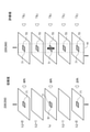
- FIG. 10 is a conceptual diagram for explaining the lesion candidate space 85 (described later), the integrated lesion candidate space 87 (described later), and the like in each of the plurality of slice image groups.
- the nine large rectangular parallelepipeds on the left half of FIG. 10 correspond to the nine sliced image groups 210, respectively.
- a thick line drawn in a parallelogram shape in each of the nine large rectangular parallelepipeds indicates one cross section (slice cross section) in each slice image group 210.
- the three rectangular parallelepipeds in the middle row are three slice image groups 210 (in order from the left, slice image group 210 by coronal cross section, slice by axial cross section).
- the image group 210 and the sliced image group 210 with a rectangular parallelepiped cross section are conceptually shown.
- a slice image group 210 with a total of six oblique cross sections three each is conceptually shown.
- the six slice image groups 210 are slice image groups sliced with six different cross sections (with the normal direction of each of the six different oblique cross sections as the reference axis direction).
- the plurality of slice image groups 210 thus acquired are composed of hundreds to thousands or more (for example, 4,500) of images in total.
- the image processing device 30 infers each of a plurality of slice images 220 (also referred to as 240) acquired for a certain subject by using a learning model 410 (also referred to as a trained model 420) whose learning parameters are adjusted in advance. Execute the process (see FIG. 2). Specifically, using the above-mentioned trained model 420, an inference process for estimating an (unknown) lesion site (fracture site) of each slice image 240 is executed.
- a fracture site more specifically, a fracture site in the pelvis
- the inference process for example, the presence or absence of a fracture site, the position of the fracture site, and the like are specified (estimated).
- the reliability for example, 80% regarding the inference result of the fracture site is also output.
- FIG. 2 is a conceptual diagram showing the processing of the inference stage in machine learning.
- the trained model 420 is generated by adjusting the learning parameters of the learning model 410 (learning device) using a predetermined machine learning method.
- the learning model 410 for example, a neural network model composed of a plurality of layers is used. Then, by a predetermined machine learning method (deep learning, etc.), the weighting coefficients and the like (learning parameters) between the layers of a plurality of layers (input layer, (one or more) intermediate layers, output layers) in the neural network model are adjusted.
- the processing of the learning stage in such machine learning is executed in advance by, for example, the image processing apparatus 30.
- the learning model 410 (learned model 420) for executing the inference process for identifying the lesion site of the slice image is the teacher data having the lesion site (a plurality of slice image groups having a known lesion site (a plurality of slice image groups having a known lesion site). More specifically, it is generated based on a plurality of slice image groups)) and the like relating to a plurality of samples.
- the present invention is not limited to this, and the image processing device 30 may construct the trained model 420 in its own device (image processing device 30) by acquiring learning parameters adjusted by another device. good.
- the image processing device 30 executes further processing based on the inference result using the trained model 420 by machine learning. Specifically, as will be described later, the image processing apparatus 30 executes a lesion candidate space 85 formation process (including an expansion space 83 formation process), an integrated lesion candidate space 87 formation process, and the like. Perform fracture detection processing.
- a lesion candidate space 85 formation process including an expansion space 83 formation process
- an integrated lesion candidate space 87 formation process and the like. Perform fracture detection processing.
- the image processing device 30 includes a controller 31, a storage unit 32, and an operation unit 35.
- the controller 31 is a control device built in the image processing device 30 and controlling the operation of the image processing device 30.
- the controller 31 is configured as a computer system including a single or a plurality of CPUs (Central processing Units) (also referred to as a microprocessor or a hardware processor).
- the controller 31 executes various types of software programs (hereinafter, also simply referred to as programs) stored in the storage unit (nonvolatile storage unit such as ROM and / or hard disk) 32 in the CPU. Realize the processing of.
- the program (specifically, a program module group) may be recorded on a portable recording medium such as a USB memory, read from the recording medium, and installed in the image processing apparatus 30. Alternatively, the program may be downloaded via a communication network or the like and installed in the image processing apparatus 30.
- the controller 31 executes, for example, processing related to the inference stage in machine learning. Specifically, each (multiple 2) of a plurality of 2D slice images 240 acquired for a certain subject using a training model 410 (trained model 420) (see FIG. 2) in which the training parameters are adjusted. Inference processing is executed for each two-dimensional slice image 240) of the dimensional slice image group 210. Further, the controller 31 also executes the formation process of the lesion candidate space 85 (including the formation process of the expansion space 83), the formation process of the integrated lesion candidate space 87, and the like. Further, the controller 31 also executes a process of outputting the lesion site (such as an image display process including the fracture site).
- the storage unit 32 is composed of a storage device such as a hard disk drive (HDD) and / or a solid state drive (SSD).
- the storage unit 32 stores a plurality of two-dimensional slice images 220, 240, 250, 290, a trained model 420 (including learning parameters), and the like.
- the operation unit 35 includes an operation input unit 35a for receiving an operation input to the image processing device 30, and a display unit 35b for displaying and outputting various information.
- the operation input unit 35a also referred to as a reception unit
- the display unit 35b displays a slice image 220 (also referred to as 290) or the like, which has undergone inference processing using the trained model 420 and subsequent various processing.
- a mouse, keyboard, or the like is used as the operation input unit 35a
- a display liquid crystal display or the like
- a touch panel that also functions as a part of the operation input unit 35a and also as a part of the display unit 35b may be provided.
- the image processing device 30 is also referred to as a medical image processing device, and the image processing system 10 is also referred to as a medical image processing system.
- FIG. 3 is a flowchart showing the processing of the image processing device 30 (specifically, the controller 31 (FIG. 1)).
- FIG. 3 shows a process including an inference process (step S32) using the trained model 420 by machine learning.
- step S31 the controller 31 acquires (inputs) the second two-dimensional slice image group Gi (the initial value of the value i is "1" here) in response to the designated operation by the operating user. Specifically, the operation user specifies the storage folder and file name of the second two-dimensional slice image group Gi (210), and the controller 31 determines the data of the i-th slice image group Gi based on the specified contents. Is read.
- the operation user specifies the storage folder and file name of the second two-dimensional slice image group Gi (210), and the controller 31 determines the data of the i-th slice image group Gi based on the specified contents. Is read.
- the controller 31 uses the trained model 420 for each of the plurality of two-dimensional slice images 240 constituting the i-th two-dimensional slice image group Gi (also simply referred to as the i-th slice image group). Perform inference processing. Specifically, a region estimated as a lesion region (also referred to as a “lesion estimation region” (71)) in the i-slice image group Gi (210) by the trained model 420 (learning device) is obtained.
- a lesion region also referred to as a “lesion estimation region” (71)
- FIG. 6 is a diagram showing an example of the lesion estimation region 71.
- the lesion estimation area 71 is shown surrounded by a bounding box 51 (a thick black frame having a rectangular shape). That is, the estimation result regarding the fracture site by the trained model 420 (learning device) is shown.
- the lesion estimation region 71 is detected in at least a part of the two-dimensional slice images constituting the i-th slice image group Gi.
- lesions are estimated only in the three slice images L (j-1), Lj, and L (j + 3) of the five two-dimensional slice images L (j-1) to L (j + 3) in FIG. Region 71 has been detected.
- the lesion estimation region 71 is not detected in the two slice images L (j + 1) and L (j + 2). That is, in the inference processing by the trained learner (learned model 420), the lesion site is overlooked (missing detection) in some slice images.
- the lesion estimation area 71 should be detected in two slice images (for example, L (j + 1) (and L (j + 2))) in the vicinity of the slice image (for example, Lj) in which the lesion estimation area 71 is detected. Is. Nevertheless, the lesion estimation region 71 is not actually detected in the two slice images.
- the expansion space 83 based on the lesion estimation region 71 is formed for each of all (N) slice image groups 210 (Gi), and the space including the expansion space 83 is formed. It is formed as a lesion candidate space 85 (step S33).
- step S33 first, the controller 31 forms the expansion space 83.
- the value k is the number of all the slice images in which the lesion estimation region 71 is detected
- the value M is a natural number.
- the direction near the normal is a direction (including the normal direction (itself)) within a predetermined angle with respect to the normal direction of each slice image Lj (specifically, its cross section).
- the normal direction (itself) of each slice image Lk is exemplified as the normal direction, but the direction near the normal is not limited to this, and the normal direction of each slice image Lk is, for example, 10.
- the direction may have an inclination angle of about 20 degrees (deg) to 20 degrees (deg).
- FIG. 7 is a conceptual diagram for explaining the expansion space 83.
- one two-dimensional slice image Lk also referred to as 220 or 250
- the lesion estimation region 71 is detected is shown among the plurality of slice images Lj.
- An expansion space 83 (also referred to as 83A) for one slice image Lk is formed (see right column of FIG. 7).
- the expansion space 83A (particularly, see the bottom of the right column of FIG. 7) with respect to one slice image Lk is shown.
- Forming such an expansion space 83A is not limited to the slice image Lk, but the slice images L (k-2), L (k-1), L (k + 1), and L (k + 1), L (k + 1), L (k + 1), L (k + 1), L (k + 1), L (k + 1), L (k + 1), L (k + 1), L (k + 1), L (k + 1) Also in (k + 2), it corresponds to setting the lesion estimation area 71 (also referred to as a deemed lesion estimation area 73) (see the right column of FIG. 7). Since the lesion estimation region (deemed lesion estimation region) 73 set in the expansion space 83A is a conceptually expanded lesion estimation region, it is also referred to as an expanded lesion estimation region or the like.
- the deemed lesion estimation region 73 in the slice image in the vicinity of the slice image Lk is the same position as the position (two-dimensional position) in the slice image Lk. It is set to (two-dimensional position).
- the position of the deemed lesion estimation region 73 in the slice image near the slice image Lk is slightly deviated from the position in the slice image Lk, but there is no significant effect. ..
- expansion space 83 (expansion space 83A for one slice image Lk) is formed for all the slice image Lk in which the lesion estimation region 71 is detected among the plurality of slice images Lj.
- the expansion space 83 for all slice images Lk (specifically, the aggregate space (logical sum space) of the expansion space 83 (83A) for each slice image Lk) (also referred to as 83B) is on the upper right side of FIG. (And the rightmost column in FIG. 8).
- FIG. 8 is a conceptual diagram for explaining the expansion space 83 (83B) and the like related to all slice images Lk of a certain i-slice image group Gi.
- the second column from the left in FIG. 8 shows a state in which the lesion estimation regions 71 in the plurality of slice images 220 are stacked in the vertical direction.
- the lesion estimation area 71 is schematically shown by a thick line segment, and the thickness thereof is discarded. However, the lesion estimation area 71 in the uppermost stage and the lowermost stage is drawn even in a state having a thickness (slice thickness) (see a horizontally long rectangular area indicated by a thin line).
- the thick broken line segment in the second column from the left in FIG. 8 indicates that the lesion estimation region 71 does not exist in some of the slice images in the series of slice images (the lesion site is overlooked). That is).
- the assembly space 81 is a collection of lesion estimation regions 71 (that is, a thin plate-like space (thin rectangular parallelepiped space)) having a predetermined slice thickness.
- the assembly space 81 is a collection of lesion estimation regions 71 (that is, a thin plate-like space (thin rectangular parallelepiped space)) having a predetermined slice thickness.
- a portion of a series of slice images in which the lesion estimation region 71 does not exist is schematically shown by a thick solid line segment.
- the thick solid line (thick solid line in the leftmost column of FIG. 8) indicates a portion excluded from the collective space 81 of the lesion estimation region 71 (unlike the thick solid line in the second column from the left in FIG. 8). There is.
- each expansion space 83A for each lesion estimation region 71 The third column from the left in FIG. 8 shows each expansion space 83A for each lesion estimation region 71.
- each expansion space 83A is shown laterally compressed and its lateral positions offset from each other.
- the length (thickness) of each expansion space 83A in the vertical direction corresponds to the thickness of five slices.
- an aggregate space (aggregate) 83B of the expansion space 83A is formed.
- the expansion space 83 (individual expansion space 83A) for each slice image Lk (each lesion estimation region 71) and the expansion space 83 (individual expansion space) for all slice images Lk (all lesion estimation regions 71).
- the relationship with the collective space 83B) of 83 is shown.
- An individual expansion space 83A formed by expanding the lesion estimation region 71 of each slice image Lk in the normal direction is formed, and the individual expansion spaces 83A are formed while overlapping with each other, thereby expanding as a whole.
- the expanded space 83B is formed. More specifically, the expansion space 83A having a predetermined thickness (thickness corresponding to the thickness of five slices) partially overlaps the position in the vertical direction with respect to the plurality of lesion estimation regions 71 adjacent to each other in the vertical direction.
- the aggregate space (aggregate) 83B of the expansion space 83A is formed by being sequentially generated.
- the lesion estimation region 71 is missing (4) or less in a continuous predetermined number (2 * M) (here, 4) or less. Even if the lesion site is overlooked), the expansion space 83B is formed so as to complement the missing lesion estimation region 71.
- the controller 31 forms a space including the expansion space 83 as the lesion candidate space 85 (step S33). Specifically, a logical sum space of the expansion space 83 (here, the collective space 83B of the expansion space 83A relating to the plurality of slice images Lk) and the collective space 81 of the lesion estimation region 71 is formed as the lesion candidate space 85.
- the expansion space 83B aggregate space 83B of the individual expansion space 83A relating to the plurality of slice images Lk includes the aggregate space 81 of the lesion estimation region 71, the expansion space 83B and the aggregate space 81 of the lesion estimation region 71
- the OR space of is equivalent to the expansion space 83B (itself).
- the OR operation is not performed.
- the expansion space 83B (itself) may be regarded as a logical sum space of the expansion space 83B and the aggregate space 81 of the lesion estimation region 71.
- FIG. 9 is a conceptual diagram for explaining the lesion candidate space 85.
- the three-dimensional model 80 of the subject three-dimensional volume data configured by using the slice image group of the subject
- a rectangular parallelepiped the largest rectangular parallelepiped
- the lesion estimation region 71 is detected in at least a part of the slice images constituting the i-slice image group Gi. Specifically, as shown on the upper left side of FIG. 9 (and the leftmost column of FIG. 8), lesions span two or more slice images within a predetermined range B in the reference axis direction (vertical direction in FIG. 9).
- the estimated region 71 is detected, and the collective space 81 of such a lesion estimated region 71 forms a space having a substantially rectangular parallelepiped shape.
- the collective space 81 of the lesion estimation region 71 is a collective space of a portion (thin rectangular parallelepiped space) having a two-dimensional plane region having the size of the lesion estimation region 71 and the thickness of the slice image.
- it is simply expressed as the collective space 81 of the lesion estimation region 71.
- the lesion estimation region 71 may not be detected in some slice images within the predetermined range B.
- the black linear portion in the substantially rectangular parallelepiped-shaped space on the upper left side of FIG. 9 indicates that a part of the slice portion (thin plate-shaped portion) is missing (similar to the leftmost column in FIG. 8).
- the partial slice portion is a thin plate-shaped portion corresponding to a slice image (L (j + 1) or the like (see FIGS. 6 and 7) in which the lesion estimation region 71 is not detected).
- the collective space 81 of the lesion estimation region 71 is a space in which a part of the slice portion is excluded from the above-mentioned space having a substantially rectangular parallelepiped shape.
- the expansion space 83 on the upper right side of FIG. 9 such a missing portion is complemented (the expansion space 83 in FIG. 9 does not have a missing portion).
- the expansion space 83 is formed by expanding each of the lesion estimation regions 71 of all slice images Lk in the assembly space 81.
- the space including the missing portion is formed as the expansion space 83.
- the lesion candidate space 85 is formed to include the above-mentioned missing portion (to complement the missing portion), in other words, to include the missed lesion region.
- step S34 the branch processing is executed depending on whether or not the processing is completed for all the slice image group Gis. If the process is not completed, the value i is incremented (step S35), the process returns to step S31, and the processes of steps S31 to S33 are executed. On the other hand, when the processing is completed for all the slice image groups Gi (when the lesion candidate space 85 is formed for all of the N slice image groups Gi (G1 to GN)), the process proceeds to step S36.
- an integrated lesion candidate space 87 is formed by integrating N lesion candidate spaces 85.
- the integrated lesion candidate space 87 is formed as a logical sum space of N lesion candidate spaces 85. More specifically, the integrated lesion candidate space 87 is formed by integrating the lesion candidate spaces 85 of the plurality of slice image groups Gi while aligning their corresponding positions.
- the lesion candidate space 85 (9 lesion candidate spaces 85) for each of the 9 slice image groups G1 to G9 is schematically shown, and the 9 lesion candidate spaces 85 are integrated and integrated.
- the lesion candidate space 87 is schematically shown.
- the lesion region is specified based on the integrated lesion candidate space 87.
- the controller 31 finally lesions voxels belonging to more than a predetermined number (for example, 7) of voxels in the integrated lesion candidate space 87, which is less than N (for example, 7).
- N for example, 7
- the integrated lesion space 89 (the collective space of the lesion region finally identified (determined)) is schematically shown.
- the integrated lesion space 89 is a collection of voxels belonging to a larger number of voxels in the integrated lesion candidate space 87 than a predetermined number (for example, 7).
- an evaluation value "1" is given to the voxels in the lesion candidate space 85.
- Voxels outside the lesion candidate space 85 are given an evaluation value of "0" (see FIG. 10).
- the evaluation value is added for each corresponding voxel.
- the evaluation value for each voxel after addition indicates how many slice image groups Gi the lesion candidate space 85 belongs to.
- the evaluation value of a voxel is "9", it means that the voxel belongs to all (9) lesion candidate spaces 85 of the 9 slice image group Gi. Further, when the evaluation value of a certain voxel is "7”, it means that the certain voxel belongs to the lesion candidate space 85 of the seven slice image group Gi. Further, when the evaluation value of a certain voxel is "0”, it means that the certain voxel does not belong to any of the lesion candidate spaces 85 of the nine slice image group Gi.
- the integrated lesion space 89 may be defined as an aggregate including voxels belonging to less than a predetermined number of lesion candidate spaces 85.
- voxels belonging to only a small number of lesion candidate spaces 85 are not actually voxels related to the lesion region. .. Therefore, it is determined as a lesion region on condition that it is a voxel detected as a lesion estimation region 71 (or a deemed lesion estimation region 73) even in the lesion candidate space 85 of a large number of other slice image groups Gi. Is preferable.
- the voxel is determined as a lesion region on condition that the voxel is detected as a lesion estimation region 71 even when viewed from another angle. Therefore, here, voxels belonging to a larger number of lesion candidate spaces 85 than a predetermined number (for example, 7) are finally determined as a lesion region.
- step S38 the lesion area of the two-dimensional slice image 220 is displayed with respect to the slice image group Gi designated by the user. Specifically, in the slice image including the voxels belonging to the integrated lesion space 89, the bounding box 51 is drawn so as to surround the voxels belonging to the integrated lesion space 89. For example, as shown in FIG. 11, the lesion area in the slice images L (j + 1), L (j + 2) may also be shown with the bounding box 51 attached. Note that FIG. 11 is a diagram showing an example of the two-dimensional slice image 220 (290) displayed in step S38.
- the lesion candidate space 85 including the expansion space 83 is formed for at least one slice image group (here, a plurality of slice image groups) Gi, the lesion site in the two-dimensional slice image is formed. It is possible to suppress oversight.
- an integrated lesion candidate space 87 is formed in consideration of the lesion candidate space 85 of a plurality of slice image groups having cross sections in different directions. Therefore, it is possible to improve the detection accuracy of the lesion site (for example, suppress over-detection) as compared with the case where only the lesion candidate space 85 of one slice image group with a cross section in a specific direction is considered. be.
- voxels belonging to a larger number of lesion candidate spaces 85 than a predetermined number of less than N are determined as lesion regions, so that false detection (overdetection) of the lesion region is performed. It is possible to suppress it.
- steps S32 and S33 is executed every time the i-slice image group Gi is specified in step S31, but the present invention is not limited to this.
- all of the plurality of slice image groups 210 for example, nine slice image groups 210) of a certain subject may be designated at one time.
- inference processing or the like may be performed on the plurality of slice image groups 210 after that.
- the evaluation value "1" is uniformly given to the voxels in the lesion candidate space 85 of each slice image group Gi, but the present invention is not limited to this.
- “1” For a voxel corresponding only to the assumed lesion estimation region 73 in the lesion candidate space 85 (a voxel corresponding to a region not detected as the lesion estimation region 71 by the trained model 420), “1”.
- a value reduced from the above (for example, "0.5") may be given as an evaluation value. In other words, it may be treated as a voxel belonging to the 0.5 slice image group Gi.
- the second embodiment is a modification of the first embodiment.
- the differences from the first embodiment will be mainly described.
- voxels belonging to a larger number of lesion candidate spaces 85 than a predetermined number (less than N) are determined as lesion regions (FIG. 3). See step S37).
- the lesion region is determined based on the evaluation value (evaluation value for determining multiple multiples) according to the multiple layers of the lesion candidate space 85 (for each slice image group Gi) in each voxel (FIG. 10). See also).
- the present invention is not limited to this.
- the evaluation value (specifically, the evaluation based on the reliability calculated by the trained model 420 for the lesion estimation region 71 of each slice image group Gi).
- Voxels with a value higher than a predetermined level may be determined as a lesion area.
- the lesion area may be determined based on the evaluation value assigned to each voxel according to the reliability of the lesion estimation area 71. In this second embodiment, such an embodiment will be described.
- the evaluation value is also expressed as an evaluation value for calculating the integrated reliability (described later).
- step S37 the same process as in FIG. 3 is executed. However, in the second embodiment, a process different from that of the first embodiment is executed in step S37.
- step S37 the controller 31 first calculates the evaluation value (for each slice image group) for each of the N slice image groups for each voxel in the three-dimensional model 80 of the subject. ..
- the evaluation value (for each slice image group) is calculated based on the reliability calculated by the trained model 420 for the lesion estimation region 71 in the lesion candidate space 85 of each slice image group. Then, the evaluation value of N slice image group Gi is given to each voxel.
- evaluation values (“0” to “10”) are given to the voxels in each lesion candidate space 85 in the three-dimensional model 80.
- FIG. 12 is a conceptual diagram showing how voxels in each lesion candidate space 85 are given evaluation values.
- the voxels outside the lesion candidate space 85 are given an evaluation value of "0" (see FIG. 12).
- any of the evaluation values "1" to "10” is given to the voxels in the lesion candidate space 85 of the i-slice image group Gi.
- FIG. 13 is a diagram showing an example of evaluation values given to each voxel of a plurality of lesion estimation regions 71 of a certain slice image group.
- the reliability of the lesion estimation region 71 of a certain slice image Lj of the i-th slice image group Gi is "80%" (reliability of determination that the lesion is a lesion site).
- the evaluation value “8” is given to the voxel of the slice portion corresponding to the lesion estimation region 71.
- the reliability "20%” is calculated for each lesion estimation region 71 of the other slice image L (j-2), the voxels of the slice portion corresponding to the lesion estimation region 71 are evaluated. The value "2" is given.
- the voxels inside the expansion space 83 and outside the collective space 81 of the lesion estimation region 71 are complemented so as to be included in the expansion space 83.
- the evaluation value is calculated as follows for the voxel of the slice portion corresponding to the deemed lesion estimation area 73. Specifically, the reliability calculated for the lesion estimation region 71 corresponding to the deemed lesion estimation region 73 (lesion estimation region 71 corresponding to the individual expansion space 83 (lesion estimation region 71 of the expansion source)). The evaluation value is calculated based on the degree.
- a lesion estimation region 73 of a slice image L (j + 1) of the i-slice image group Gi there are two lesion estimation regions 71 (slices) of the expansion source.
- An evaluation value "8" is given based on the reliability "80%” and "80%” of the lesion estimation area 71 of the image L (j + 2) and the lesion estimation area 71) of the slice image Lj.
- the present invention is not limited to this, and for each deemed lesion estimation region 73 (specifically, among the deemed lesion estimation regions 73, the region not detected as the lesion estimation region 71 by the trained model 420).
- a value further reduced (for example, a value halved) than the value calculated as described above may be calculated as an evaluation value.
- the value “4”, which is half of the value “8” (see FIG. 13) calculated as described above is calculated as the evaluation value. May be done.
- a value "2.5" which is half of the value "5" calculated as described above, is calculated as an evaluation value. You may.
- the controller 31 adds the evaluation value for each corresponding voxel when integrating a plurality of slice image groups Gi.
- the integrated reliability may be the addition value (total value) itself of the evaluation values for each of the N slice image groups, but is not limited to this, and the average value (addition average value) of the addition values is not limited to this. And so on.
- the controller 31 determines a voxel having an integrated reliability higher than a predetermined level as a lesion region among a plurality of voxels in the integrated lesion candidate space 87. For example, a voxel having an integrated reliability of an evaluation value of "70" or more is determined as a lesion region.
- voxels having an integrated reliability higher than a predetermined level are determined as the lesion region. Therefore, it is possible to satisfactorily suppress erroneous detection (overdetection) of the lesion area.
- Step S38 the slice image group Gi specified by the user is displayed immediately after step S37, but the present invention is not limited to this.
- the slice image group determined based on the evaluation value Vi (evaluation value for image group selection) for each slice image group Gi may be automatically displayed immediately after step S37. More specifically, the lesion area in the slice image group may be surrounded by a bounding box 51 or the like and displayed.
- the evaluation value Vi may be calculated based on the reliability calculated by the trained model 420 for the lesion estimation region 71 in each slice image group Gi.
- the fracture region (lesion region) is displayed using the i-th slice image group Gi sliced in a cross section (cross-section direction having high reliability) including (many) the lesion estimation region 71 having high reliability. For example, it is possible to increase the possibility that the fracture site is properly (easily seen) displayed.
- step S38 (see FIGS. 5 and 14) according to the second embodiment, the controller 31 first executes the process of step S51.
- FIG. 14 is a flowchart showing the process of step S38 (also referred to as S38C) according to the modified example.
- step S51 the controller 31 determines the evaluation value Vi for each slice image group Gi (for example, V1 in FIG. 15) based on the reliability calculated by the trained model 420 for the lesion estimation region 71 in each slice image group Gi. ⁇ V9) are calculated respectively.
- FIG. 15 is a conceptual diagram showing how the evaluation value Vi of each slice image group Gi is calculated.
- the aggregate space 81 of the lesion estimation region 71 is further simplified and shown (the illustration of the missing lesion estimation region 71 in the aggregate space 81 is omitted).
- the evaluation value Vi for each slice image group Gi is an evaluation value (evaluation value for image group selection) for selecting an image group to be displayed. Since the evaluation value Vi is also an evaluation value for selecting the cross-sectional direction to be displayed, it is also referred to as a direction evaluation value.
- the evaluation value Vi may be calculated as, for example, the average value of the plurality of reliabilitys given to the plurality of lesion estimation regions 71 in the slice image group Gi. Alternatively, the evaluation value Vi may be calculated as the highest value (maximum value) among the plurality of reliability imparted to the plurality of lesion estimation regions 71 in the slice image group Gi.
- the controller 31 determines the slice image group Gi (slice image group Gi to be displayed) to be used based on the plurality of evaluation values Vi (V1 to V9 in FIG. 15). For example, among the N slice image groups Gi, the slice image group having the highest evaluation value Vi is determined as the slice image group Gi to be used.
- step S53 the controller 31 displays the lesion region on the display unit 35b using the determined slice image group Gi (specifically, the two-dimensional slice image 220 (290) relating to the slice image group Gi). ..
- the slice image group determined based on the evaluation value Vi (evaluation value for image group selection) is automatically displayed immediately after step S37, so that the fracture site is appropriately (easily seen) displayed. It can increase the possibility of being done.
- the above evaluation value Vi may be calculated as the number of lesion estimation regions 71 having a reliability equal to or higher than a predetermined threshold value (for example, 80%) among a plurality of lesion estimation regions 71 in the slice image group Gi. good.
- a predetermined threshold value for example, 80%
- each slice image group Gi the number (number of sheets) of slice images (also referred to as specific slice images) including the lesion estimation area 71 may be calculated as the evaluation value Vi.
- the number of specific slice images (slice images including the lesion estimation region 71 estimated as the lesion region by the trained model 420) may be calculated in each of the N slice image groups Gi.
- the lesion area is automatically displayed using the slice image related to the slice image group Gi (slice image group having the highest evaluation value Vi) having the largest number of specific slice images among the N slice image groups. You may.
- the slice image group Gi having the highest evaluation value Vi among the N slice image group Gi is determined as the slice image group Gi to be displayed, but the present invention is not limited to this.
- the slice image group Gi having the highest evaluation value Vi among the predetermined slice image group Gi for example, three slice image groups G4, G5, G6 relating to the coronal cross section, the axial cross section, and the sagittal cross section
- the expansion space 83 is formed and the lesion candidate space 85 based on the expansion space 83 is formed for all of the N slice image groups Gi, but the present invention is not limited to this. ..
- the expansion space 83 may not be formed and the aggregate space 81 of the lesion estimation region 71 may be obtained as it is as the lesion candidate space 85.
- the expansion space 83 is not formed and the aggregate space 81 of the lesion estimation region 71 is obtained as it is as the lesion candidate space 85. May be good.
- the remaining slice image group Gi at least one slice image group Gi
- the expansion space 83 is formed, and the expansion space 83 (specifically, the collective space 83B of the expansion space 83A) and the lesion estimation area 71.
- the logical sum space with the aggregate space 81 may be obtained as the lesion candidate space 85.
- the expansion space 83 (specifically, the collective space 83B of the expansion space 83A) itself may be obtained as the lesion candidate space 85.
- the expansion space 83 is formed and the expansion space 83 (specifically, the aggregate space 83B of the expansion space 83A) is formed. ) May be obtained as the lesion candidate space 85.
- the expansion space 83 may not be formed and the aggregate space 81 of the lesion estimation region 71 may be obtained as the lesion candidate space 85.
- the remaining slices are sliced.
- the collective space 81 of the lesion estimation region 71 estimated by the learner as the lesion region in each of the image groups may be formed as the lesion candidate space for the sliced image group.
- the remaining slice image groups other than the predetermined number of slice image groups Gi may not exist. That is, as described above, the expansion space 83 may be formed and the lesion candidate space 85 based on the expansion space 83 may be formed for all of the N slice image groups Gi.
- each slice image group Gi may be changed according to the detection result of the lesion estimation region 71. Specifically, in a certain slice image group Gi, when the lesion estimation region 71 is detected without being missing in a series of consecutive slice images (all slice images Lk in which the lesion estimation region 71 is detected are in the middle. The expansion space 83 may not be formed for the slice image group Gi.
- each slice image group Gi all lesion estimation regions 71 (all regions estimated as lesion regions by the trained model 420 (learning device)) are each expanded to expand the space. 83 is formed.
- the expansion space for all slice images Lk logical sum space of individual expansion spaces 83A having each of all slice image Lk in which the lesion estimation region 71 is detected as an expansion source. Is required as the expansion space 83 (83B) for the i-th slice image group Gi.
- the present invention is not limited to this.
- the logical sum space (aggregate space) of the expansion space 83A relating to only a part of the slice image Lk of all the slice image Lk is the expansion space relating to the slice image group Gi. It may be obtained as 83 (83B). Then, a logical sum space of the expansion space 83B and the aggregate space 81 of the lesion estimation region 71 may be formed as the lesion candidate space 85. In other words, the logical sum space of the expansion space 83A for at least one slice image of all the slice images Lk and the aggregate space 81 of the lesion estimation region 71 may be formed as the lesion candidate space 85.
- all lesion estimation regions 71 (two or more lesion estimation regions 71) estimated as lesion regions in each slice image (two or more slice images) of the slice image group Gi.
- the lesion estimation area 71 calculated by the trained model 420 with its reliability as a value equal to or higher than a predetermined threshold is virtually expanded in the direction near the normal line of the slice image to form an expansion space 83. May be good.
- the lesion estimation of the lesion estimation region 71 (slice images Lj, L (j + 2) (FIG. 13) calculated by the trained model 420 as a value whose reliability is equal to or higher than a predetermined threshold value (for example, 40%)).
- the region 71) may be virtually expanded in the direction near the normal of the slice image to form the (individual) expansion space 83A.
- it is based on the lesion estimation region 71 (lesion estimation region 71 of the slice image L (j-2)) calculated by the trained model 420 as a value whose reliability is less than a predetermined threshold value (for example, 40%) (individual).
- the expansion space 83A does not have to be formed.
- one expansion space 83A (also 83B) based on only one lesion estimation region 71 detected in one slice image of the slice images Lj, L (j + 2) is formed, and the one expansion space 83A is formed.
- a logical sum space of the lesion estimation region 71 and the aggregate space 81 of the lesion estimation region 71 may be formed as the lesion candidate space 85.
- the expansion space 83 (83A, 83B) is a lesion estimation region (specifically, at least one slice image) estimated by the learner as a lesion region in each slice image (specifically, at least one slice image) of the slice image group Gi.
- At least one lesion estimation region may be formed by virtually expanding in the direction near the normal. Then, a logical sum space of the formed expansion space 83 (specifically, at least one expansion space 83A) and the aggregate space 81 of the lesion estimation region 71 may be formed as the lesion candidate space 85.
- the lesion estimation region 71 (lesion estimation region 71 of the slice image L (j-2), etc.) calculated by the trained model 420 as a value whose reliability is less than a predetermined threshold is the aggregate space of the lesion estimation region 71. It may also be excluded from 81. In other words, the lesion estimation region 71 having a certain degree of reliability or less may be regarded as not the lesion estimation region 71.
- the expansion space 83 (83A) is formed by expanding the lesion estimation region 71 in the vicinity of the normal while maintaining the size of the lesion estimation region 71.
- the present invention is not limited to this.
- the expansion space 83 (83A) makes the lesion estimation region 71 perpendicular to the direction perpendicular to the normal direction (specifically, all directions in the plane perpendicular to the normal direction) (vertical to the normal vicinity direction). It may be formed by expanding (expanding) gradually (in a plane) in the vicinity of the normal.
- the expansion space 83 (83A) may be formed by expanding the lesion estimation region 71 (its area) gradually in the vicinity of the normal.
- FIG. 16 is a diagram showing such a modified example.
- the estimated lesion estimation region 73 in the slice image L (k + 1) is one size larger than the lesion estimation region 71 (estimated lesion estimation region 73) in the slice image Lk.
- the estimated lesion estimation area 73 in the slice image L (k + 2) is one size larger than the estimated lesion estimation area 73 in the slice image L (k + 1).
- the estimated lesion estimation area 73 of the slice image L (k + 1) and the estimated lesion estimation area 73 of the slice image L (k + 2) gradually expanded the lesion estimation area 71 by a predetermined ratio (20%). Has a size.
- the lesion estimation area 73 of the slice image L (k-1) and the lesion estimation area 73 of the slice image L (k-2) also have the lesion estimation area 71 at a predetermined ratio (20%) each. It has a gradually expanded size.
- the center position (two-dimensional position) of each deemed lesion estimation area 73 and the center position of the lesion estimation area 71 are the same.
- the expansion space 83 may be formed as a space in which the lesion estimation region 71 is expanded into a (reverse) quadrangular pyramid shape in the direction near the normal of the lesion estimation region 71.
- the two-dimensional position change (in the two-dimensional plane of the fracture site) due to the departure from the slice image Lk in the direction near the normal line.
- An expansion space 83 that allows a change in position) can be formed.
- the case where the fracture site is one place is mainly described, but the same idea as described above can be applied to the case where there are a plurality of fracture sites.
- a plurality of lesion candidate spaces 85 are formed in each slice image group Gi
- a plurality of integrated lesion candidate spaces 87 are formed.
- the plurality of lesion candidate spaces 85 and the plurality of integrated lesion candidate spaces 87 in each slice image group Gi are formed as spaces corresponding to a plurality of fracture sites, respectively.
- FIG. 17 is a conceptual diagram showing such labeling and the like.
- label E1 is attached to one of the plurality of integrated lesion candidate spaces 87 formed in step S36, and the other integrated lesion candidate space 87 is labeled with “label E1”.
- Label E2 is attached.
- FIG. 17 for simplification of the illustration only the plurality of lesion candidate spaces 85 formed in one slice image group Gi are shown, and the other slice image group Gi is omitted.
Landscapes
- Health & Medical Sciences (AREA)
- Life Sciences & Earth Sciences (AREA)
- Engineering & Computer Science (AREA)
- Physics & Mathematics (AREA)
- Medical Informatics (AREA)
- Molecular Biology (AREA)
- Animal Behavior & Ethology (AREA)
- Pathology (AREA)
- Veterinary Medicine (AREA)
- Biomedical Technology (AREA)
- Heart & Thoracic Surgery (AREA)
- Nuclear Medicine, Radiotherapy & Molecular Imaging (AREA)
- Public Health (AREA)
- Surgery (AREA)
- Biophysics (AREA)
- General Health & Medical Sciences (AREA)
- High Energy & Nuclear Physics (AREA)
- Radiology & Medical Imaging (AREA)
- Optics & Photonics (AREA)
- Computer Vision & Pattern Recognition (AREA)
- General Physics & Mathematics (AREA)
- Theoretical Computer Science (AREA)
- Apparatus For Radiation Diagnosis (AREA)
- Image Analysis (AREA)
Priority Applications (1)
| Application Number | Priority Date | Filing Date | Title |
|---|---|---|---|
| JP2022545719A JPWO2022045277A1 (https=) | 2020-08-31 | 2021-08-27 |
Applications Claiming Priority (2)
| Application Number | Priority Date | Filing Date | Title |
|---|---|---|---|
| JP2020145353 | 2020-08-31 | ||
| JP2020-145353 | 2020-08-31 |
Publications (1)
| Publication Number | Publication Date |
|---|---|
| WO2022045277A1 true WO2022045277A1 (ja) | 2022-03-03 |
Family
ID=80353401
Family Applications (1)
| Application Number | Title | Priority Date | Filing Date |
|---|---|---|---|
| PCT/JP2021/031453 Ceased WO2022045277A1 (ja) | 2020-08-31 | 2021-08-27 | 画像処理装置、画像処理システム、画像処理方法、およびプログラム |
Country Status (2)
| Country | Link |
|---|---|
| JP (1) | JPWO2022045277A1 (https=) |
| WO (1) | WO2022045277A1 (https=) |
Citations (3)
| Publication number | Priority date | Publication date | Assignee | Title |
|---|---|---|---|---|
| JPH07146954A (ja) * | 1993-11-25 | 1995-06-06 | Hitachi Medical Corp | 医用画像診断装置 |
| JP2019531783A (ja) * | 2016-08-26 | 2019-11-07 | エレクタ、インク.Elekta, Inc. | 畳み込みニューラルネットワークを用いた画像セグメンテーションのためのシステムおよび方法 |
| JP2020032043A (ja) * | 2018-08-31 | 2020-03-05 | 富士フイルム株式会社 | 画像処理装置、方法およびプログラム |
-
2021
- 2021-08-27 JP JP2022545719A patent/JPWO2022045277A1/ja active Pending
- 2021-08-27 WO PCT/JP2021/031453 patent/WO2022045277A1/ja not_active Ceased
Patent Citations (3)
| Publication number | Priority date | Publication date | Assignee | Title |
|---|---|---|---|---|
| JPH07146954A (ja) * | 1993-11-25 | 1995-06-06 | Hitachi Medical Corp | 医用画像診断装置 |
| JP2019531783A (ja) * | 2016-08-26 | 2019-11-07 | エレクタ、インク.Elekta, Inc. | 畳み込みニューラルネットワークを用いた画像セグメンテーションのためのシステムおよび方法 |
| JP2020032043A (ja) * | 2018-08-31 | 2020-03-05 | 富士フイルム株式会社 | 画像処理装置、方法およびプログラム |
Also Published As
| Publication number | Publication date |
|---|---|
| JPWO2022045277A1 (https=) | 2022-03-03 |
Similar Documents
| Publication | Publication Date | Title |
|---|---|---|
| CN112529834B (zh) | 病理图像模式在3d图像数据中的空间分布 | |
| CN104573309B (zh) | 用于计算机辅助诊断的设备和方法 | |
| KR101805619B1 (ko) | 3차원 의료 영상으로부터 최적의 2차원 의료 영상을 자동으로 생성하는 방법 및 장치 | |
| JP2023511300A (ja) | 医用画像における解剖学的構造を自動的に発見するための方法及びシステム | |
| US20090309874A1 (en) | Method for Display of Pre-Rendered Computer Aided Diagnosis Results | |
| US8659602B2 (en) | Generating a pseudo three-dimensional image of a three-dimensional voxel array illuminated by an arbitrary light source by a direct volume rendering method | |
| US11229377B2 (en) | System and method for next-generation MRI spine evaluation | |
| WO2018070285A1 (ja) | 画像処理装置、及び画像処理方法 | |
| JP2018175217A (ja) | 画像処理装置および方法並びにプログラム | |
| US9361711B2 (en) | Lesion-type specific reconstruction and display of digital breast tomosynthesis volumes | |
| US9530238B2 (en) | Image processing apparatus, method and program utilizing an opacity curve for endoscopic images | |
| US8149237B2 (en) | Information processing apparatus and program | |
| US20050197558A1 (en) | System and method for performing a virtual endoscopy in a branching structure | |
| EP2266457B1 (en) | Intermediate image generating method, device, and program | |
| WO2022045277A1 (ja) | 画像処理装置、画像処理システム、画像処理方法、およびプログラム | |
| EP4270311B1 (en) | Image identification program, image identification method, image identification device | |
| Newson et al. | Encoder-decoder convolutional neural network for simple CT segmentation of COVID-19 infected lungs | |
| JP4597331B2 (ja) | 医用画像表示装置 | |
| JP7687587B2 (ja) | 画像処理装置、画像処理方法およびプログラム | |
| JP4572401B2 (ja) | 医療用三次元可視化画像の自動最適化 | |
| JP2008067915A (ja) | 医用画像表示装置 | |
| JP2025146147A (ja) | 画像処理装置、方法およびプログラム、並びに学習装置、方法およびプログラム | |
| JP2023173115A (ja) | 画像認識プログラム、画像認識方法および画像認識装置 | |
| WO2022071160A1 (ja) | 診断支援装置、診断支援装置の作動方法、診断支援装置の作動プログラム、並びに認知症診断支援方法 | |
| JP2021074360A (ja) | 医用画像処理装置及び医用画像処理方法、医用画像処理プログラム |
Legal Events
| Date | Code | Title | Description |
|---|---|---|---|
| 121 | Ep: the epo has been informed by wipo that ep was designated in this application |
Ref document number: 21861698 Country of ref document: EP Kind code of ref document: A1 |
|
| ENP | Entry into the national phase |
Ref document number: 2022545719 Country of ref document: JP Kind code of ref document: A |
|
| NENP | Non-entry into the national phase |
Ref country code: DE |
|
| 122 | Ep: pct application non-entry in european phase |
Ref document number: 21861698 Country of ref document: EP Kind code of ref document: A1 |