WO2022045253A1 - 数値制御システム及び干渉チェック支援方法 - Google Patents
数値制御システム及び干渉チェック支援方法 Download PDFInfo
- Publication number
- WO2022045253A1 WO2022045253A1 PCT/JP2021/031376 JP2021031376W WO2022045253A1 WO 2022045253 A1 WO2022045253 A1 WO 2022045253A1 JP 2021031376 W JP2021031376 W JP 2021031376W WO 2022045253 A1 WO2022045253 A1 WO 2022045253A1
- Authority
- WO
- WIPO (PCT)
- Prior art keywords
- axis
- machine
- machine element
- control
- information
- Prior art date
- Legal status (The legal status is an assumption and is not a legal conclusion. Google has not performed a legal analysis and makes no representation as to the accuracy of the status listed.)
- Ceased
Links
Images






Classifications
-
- G—PHYSICS
- G05—CONTROLLING; REGULATING
- G05B—CONTROL OR REGULATING SYSTEMS IN GENERAL; FUNCTIONAL ELEMENTS OF SUCH SYSTEMS; MONITORING OR TESTING ARRANGEMENTS FOR SUCH SYSTEMS OR ELEMENTS
- G05B19/00—Program-control systems
- G05B19/02—Program-control systems electric
- G05B19/18—Numerical control [NC], i.e. automatically operating machines, in particular machine tools, e.g. in a manufacturing environment, so as to execute positioning, movement or co-ordinated operations by means of program data in numerical form
- G05B19/406—Numerical control [NC], i.e. automatically operating machines, in particular machine tools, e.g. in a manufacturing environment, so as to execute positioning, movement or co-ordinated operations by means of program data in numerical form characterised by monitoring or safety
- G05B19/4061—Avoiding collision or forbidden zones
-
- G—PHYSICS
- G05—CONTROLLING; REGULATING
- G05B—CONTROL OR REGULATING SYSTEMS IN GENERAL; FUNCTIONAL ELEMENTS OF SUCH SYSTEMS; MONITORING OR TESTING ARRANGEMENTS FOR SUCH SYSTEMS OR ELEMENTS
- G05B19/00—Program-control systems
- G05B19/02—Program-control systems electric
- G05B19/18—Numerical control [NC], i.e. automatically operating machines, in particular machine tools, e.g. in a manufacturing environment, so as to execute positioning, movement or co-ordinated operations by means of program data in numerical form
- G05B19/406—Numerical control [NC], i.e. automatically operating machines, in particular machine tools, e.g. in a manufacturing environment, so as to execute positioning, movement or co-ordinated operations by means of program data in numerical form characterised by monitoring or safety
-
- G—PHYSICS
- G05—CONTROLLING; REGULATING
- G05B—CONTROL OR REGULATING SYSTEMS IN GENERAL; FUNCTIONAL ELEMENTS OF SUCH SYSTEMS; MONITORING OR TESTING ARRANGEMENTS FOR SUCH SYSTEMS OR ELEMENTS
- G05B19/00—Program-control systems
- G05B19/02—Program-control systems electric
- G05B19/18—Numerical control [NC], i.e. automatically operating machines, in particular machine tools, e.g. in a manufacturing environment, so as to execute positioning, movement or co-ordinated operations by means of program data in numerical form
- G05B19/408—Numerical control [NC], i.e. automatically operating machines, in particular machine tools, e.g. in a manufacturing environment, so as to execute positioning, movement or co-ordinated operations by means of program data in numerical form characterised by data handling or data format, e.g. reading, buffering or conversion of data
-
- G—PHYSICS
- G05—CONTROLLING; REGULATING
- G05B—CONTROL OR REGULATING SYSTEMS IN GENERAL; FUNCTIONAL ELEMENTS OF SUCH SYSTEMS; MONITORING OR TESTING ARRANGEMENTS FOR SUCH SYSTEMS OR ELEMENTS
- G05B2219/00—Program-control systems
- G05B2219/30—Nc systems
- G05B2219/35—Nc in input of data, input till input file format
- G05B2219/35316—Interference checking between tool, machine, part, chuck, machining range
-
- G—PHYSICS
- G05—CONTROLLING; REGULATING
- G05B—CONTROL OR REGULATING SYSTEMS IN GENERAL; FUNCTIONAL ELEMENTS OF SUCH SYSTEMS; MONITORING OR TESTING ARRANGEMENTS FOR SUCH SYSTEMS OR ELEMENTS
- G05B2219/00—Program-control systems
- G05B2219/30—Nc systems
- G05B2219/37—Measurements
- G05B2219/37237—Tool collision, interference
-
- G—PHYSICS
- G05—CONTROLLING; REGULATING
- G05B—CONTROL OR REGULATING SYSTEMS IN GENERAL; FUNCTIONAL ELEMENTS OF SUCH SYSTEMS; MONITORING OR TESTING ARRANGEMENTS FOR SUCH SYSTEMS OR ELEMENTS
- G05B2219/00—Program-control systems
- G05B2219/30—Nc systems
- G05B2219/49—Nc machine tool, till multiple
- G05B2219/49151—Axis related interference, remove hidden surfaces
Definitions
- This disclosure relates to a numerical control system and an interference check support method.
- the numerical control device moves a plurality of machine elements (tools, tables, jigs for holding a workpiece, etc.) constituting a machine tool along a plurality of control axes based on a numerical control program created in advance. Process the work. Further, the numerical control device has an interference check function for performing an interference check operation in parallel during machining by the machine tool to confirm whether the machine elements of the machine tool interfere with each other (for example, Patent Document 1). reference).
- the present disclosure has been made in view of the above problems, and provides a numerical control system and an interference check support method that support the interference check calculation in the numerical control device so that the interference check calculation can be completed in a short time.
- One aspect of the present disclosure is a numerical value that moves a plurality of machine elements of a machine tool along a plurality of axes based on a movement command and performs an interference check calculation between two machine elements combined by a predetermined set to be checked.
- the control device and the interference check support device for supporting the interference check calculation are provided, and the interference check support device is provided along the axis of each axis of the machine tool and the plurality of machine elements.
- the first storage unit that stores the first information associated with the moving machine element
- the second storage unit that stores the second information that defines the dependency between each axis in the machine, and the movement command, said.
- a numerical control system including a check target set extraction unit that extracts one or more sets of check target sets from all combinations of the plurality of machine elements based on the first information and the second information. be.
- One aspect of the present disclosure is numerical control in which a plurality of machine elements of a machine tool are moved along a plurality of axes based on a movement command and an interference check calculation is performed between two machine elements combined by a check target set.
- a method of supporting the interference check calculation in the apparatus the first information relating the movement command to each axis in the machine tool and the machine element moving along the axis among the plurality of machine elements. All combinations of the plurality of machine elements are obtained based on the movement command, the first information, and the second information, and the second information that defines the dependency between the axes in the machine tool.
- This is an interference check support method for extracting one or more sets to be checked from among them.
- the check target set extraction unit associates a movement command in a numerical control device with each axis in a machine tool and a machine element that moves along this axis among a plurality of machine elements. Based on the information and the second information that defines the dependency between each axis in the machine tool, one or more sets to be checked are extracted from all the combinations of the plurality of machine elements constituting the machine tool. do. As a result, from all combinations of multiple machine elements, except for combinations of machine elements that are obvious not to interfere (for example, combinations of machine elements that move together along an axis based on a movement command), the check target. Pairs can be extracted.
- the numerical control device moves a plurality of machine elements along a plurality of axes based on the movement command, and performs an interference check operation on the check target set extracted by the check target set extraction unit.
- the set to be checked for performing the interference check calculation can be narrowed down to only the combinations of machine elements that are not obvious to interfere, so that the interference check calculation in the numerical control device can be performed for all combinations. It can be completed in a shorter time than when it is done.
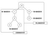
- FIG. 4 is a diagram showing a case where the first to fourth machine elements are classified into a dependent machine element group and a stationary machine element group under the machine element-control axis association information and each axis dependency information exemplified in FIG. 4A. It is a flowchart which shows the specific procedure of the check target group extraction process.
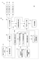
- FIG. 1 is a schematic diagram of the numerical control system 1 according to the present embodiment.
- the numerical control system 1 includes a machine tool 2 and a numerical control device (CNC) 3 for controlling the machine tool 2.
- CNC numerical control device
- the machine tool 2 has a plurality of machine elements having a predetermined three-dimensional shape such as a tool, a table, a support for supporting the tool, and a jig for holding a work, and each machine element is moved along a plurality of control axes.
- a plurality of servomotors 2a, 2b, ..., 2n and the like are provided.
- the machine tool 2 drives a plurality of servomotors 2a, ..., 2n based on a moving pulse transmitted from the numerical control device 3, and moves a plurality of machine elements along a plurality of control axes to move a work (not shown).
- the machine tool 2 is, for example, a lathe, a drilling machine, a milling machine, a grinding machine, a laser processing machine, an injection molding machine, and the like, but is not limited thereto.
- an arithmetic processing unit such as a CPU (Central Processing Unit), an auxiliary storage means such as an HDD (Hard Disk Drive) or SSD (Solid State Drive) storing various programs, and an arithmetic processing means execute a program.
- Main storage means such as RAM (Random Access Memory) for storing data temporarily required above, operation means such as a keyboard on which the operator performs various operations, display means such as a display that displays various information to the operator, etc. It is a computer composed of the hardware of.
- the numerical control device 3 has a machining program memory 31, a command analysis unit 32, an interpolation unit 33, a pulse generation unit 34, a position / orientation calculation unit 35, an interference check unit 36, a shape storage unit 37, and an interference check, depending on the hardware configuration.
- Various functions such as the support device 5 are realized.
- the machining program memory 31 stores a numerical control program including a command for moving each machine element of the machine tool 2 along each control axis (including translational movement and rotational movement).
- the numerical control program is written in a predetermined programming language (for example, G code).
- the command analysis unit 32 reads out the numerical control program stored in the machining program memory 31 for each block, analyzes it, and generates movement command data for commanding the movement of each control axis of the machine tool 2 based on the analysis result.
- the command analysis unit 32 transmits the generated movement command data to the interpolation unit 33.
- the interpolation unit 33 generates interpolation data obtained by interpolating and calculating points on the command path in a predetermined interpolation cycle based on the movement command data transmitted from the command analysis unit 32.
- the interpolation unit 33 transmits the generated interpolation data to the pulse generation unit 34.
- the pulse generation unit 34 generates a movement command for the machine tool 2, that is, a movement pulse for each of the servomotors 2a, ..., 2n of the machine tool 2 for each interpolation cycle based on the interpolation data transmitted from the interpolation unit 33. ..
- a movement command for the machine tool 2 that is, a movement pulse for each of the servomotors 2a, ..., 2n of the machine tool 2 for each interpolation cycle based on the interpolation data transmitted from the interpolation unit 33. ..
- the pulse generation unit 34 moves a plurality of machine elements of the machine tool 2 along a plurality of control axes.
- the pulse generation unit 34 When it is determined that any of the plurality of machine elements interferes with each other based on the interference check calculation described later in the interference check unit 36, the pulse generation unit 34 generates and operates a moving pulse in order to prevent this interference. Stop the input to the machine 2.
- the pulse generation unit 34 generates a moving pulse for each interpolation cycle based on the interpolation data as described above, and inputs the moving pulse to be input to the machine tool 2 in the current interpolation cycle to the machine tool 2. It is transmitted to the position / orientation calculation unit 35 before.
- the position / orientation calculation unit 35 is based on the moving pulse transmitted from the pulse generation unit 34 in each interpolation cycle, and when each control axis is moved based on the moving pulse, the position / orientation calculation unit 35 per unit time of each control axis (for example, interpolation).
- the post-movement position vector regarding the position of each machine element after the movement and the post-movement posture information regarding the posture of each machine element after moving each control axis based on the movement pulse are calculated.
- the position / orientation calculation unit 35 transmits the calculated axis movement amount vector for each control axis and the pre-movement position vector for each machine element to the interference check support device 5. Further, the position / attitude calculation unit 35 transmits the calculated post-movement position vector and post-movement attitude information for each machine element to the interference check unit 36.
- the direction and norm of the axis movement amount vector calculated by the position / orientation calculation unit 35 are defined as follows. If the control axis is a straight axis that translates the machine element along its axis, the orientation of the axis movement vector is parallel to the control axis, and the norm of the axis movement vector is the unit time along the axis of the control axis. Equal to the hit travel distance [mm]. When the control axis is a rotation axis that rotates and moves the machine element around its axis, the angular velocity vector of the control axis is used as the axis movement amount vector.
- the control axis is the rotation axis
- the direction of the axis movement amount vector is parallel to the control axis
- the norm of the axis movement amount vector is equal to the rotation angle [rad] per unit time of the control axis.
- the norm of the axis movement amount vector is also simply referred to as “axis movement amount”.
- the shape storage unit 37 stores shape information regarding the shape of each of the plurality of machine elements constituting the machine tool 2.
- a moving pulse having the same interpolation cycle as the moving pulse input from the pulse generation unit 34 to the machine tool 2 is input to the position / orientation calculation unit 35 as described above, the interference check calculation by the interference check unit 36 is performed within the interpolation cycle. It is preferable to add a small margin to the shape information stored in the shape storage unit 37 so that interference does not occur immediately even if the above cannot be completed. That is, it is preferable that the shape information stored in the shape storage unit 37 is created based on a machine element slightly larger than the actual machine element.
- the interference check unit 36 determines whether or not interference occurs between a plurality of machine elements constituting the machine tool 2 when the moving pulse generated by the pulse generation unit 34 is continuously input to the machine tool 2 as described above.
- the interference check operation for determination is performed on a plurality of check target sets.
- the check target set is configured by combining two of the plurality of machine elements constituting the machine tool 2. Therefore, when the total number of machine elements constituting the machine tool 2 is N, the total number of check target sets is N (N-1) / 2.
- the interference check unit 36 receives the post-movement position vector and the post-movement attitude information transmitted from the position / orientation calculation unit 35 for each interpolation cycle, and the interference check support device 5 for each interpolation cycle according to the procedure described later. Based on the generated interference check support information and the shape information stored in the shape storage unit 37, an interference check calculation based on a known interference check algorithm (for example, a separation axis method) is performed, and the pulse generation unit 34 performs an interference check calculation.
- a known interference check algorithm for example, a separation axis method
- the interference check support device 5 includes a first storage unit 51, a second storage unit 52, a third storage unit 53, and a check support information generation unit 54, and by using these, interference in the interference check unit 36 Interference check support information, which is information for supporting the check calculation, is generated.
- a machine element-control shaft string that associates each control axis in the machine tool 2 with a machine element that moves along the control axis related to the movement when each control axis is moved.
- the attached information is stored in an arbitrary format such as a machine configuration tree or a table. In this embodiment, a case where the machine element-control axis association information is stored in the first storage unit 51 in a machine configuration tree format as illustrated in FIG. 3 described later will be described.
- the second storage unit 52 stores information on each axis dependency relationship that defines the dependency relationship between each control axis in the machine tool 2 in an arbitrary format such as a machine component tree or a table.
- an arbitrary format such as a machine component tree or a table.
- FIG. 2 is a diagram showing an example of the machine tool 2.
- the machine tool 2 illustrated in FIG. 2 can move six machine elements 21, 22, 23, 24, 25, 26 along five control axes X, Y, Z, A, and C. ing.
- the fifth machine element 25 is a jig that supports a work (not shown), and the sixth machine element 26 is a table that supports the fifth machine element 25.
- the fifth machine element 25 and the sixth machine element 26 can be rotationally moved around a control axis C extending along a vertical direction, for example.
- the fourth machine element 24 is a tool for machining a work supported by the fifth machine element 25.
- the third machine element 23 is a support that supports the fourth machine element 24 at its tip.
- the second machine element 22 is a support that rotatably supports the base end portion of the third machine element 23 around a control shaft A extending along a horizontal plane.
- the first mechanical element 21 is a support that movably supports the second mechanical element 22 along a control axis Z along the vertical direction, and a control axis X and a control axis Y orthogonal to each other in a horizontal plane. That is, in the example of FIG. 2, the control axes X, Y, and Z are straight axes, and the control axes A and C are rotation axes.
- the fifth machine element 25 and the sixth machine element 26 are integrally carried along the control axis C. Further, the first machine element 21, the second machine element 22, the third machine element 23, and the fourth machine element 24 are integrally rotated along the control axes X, Y, and Z, and the third machine element 23 and The fourth machine element 24 is integrally rotated along the control axis A.
- FIG. 3 is a diagram showing an example of displaying the machine element-control axis association information and each axis dependency information in the machine tool 2 illustrated in FIG. 2 by a machine configuration tree.
- the control axis C and the control axes X, Y, Z, and A can be moved independently. Therefore, as shown in the machine configuration tree of FIG. 3, the control axis C and the control axes X, Y, Z, and A are independently dependent on the route R. Further, in the machine tool 2 illustrated in FIG.
- control axis A when the control axes X, Y, Z are moved, the control axis A also moves, but even if the control axis A is moved, the control axes X, Y, Z do not move. That is, the control axis A is lower than the control axes X, Y, and Z. Therefore, as shown in the machine configuration tree of FIG. 3, the control axis A is dependent on the control axes X, Y, and Z.
- the fifth machine element 25 and the sixth machine element 26 are integrally rotated along the control axis C, these machine elements 25 and 26 are connected to the control axis C as shown in the machine configuration tree of FIG. Be associated.
- the third machine element 23 and the fourth machine element 24 are integrally rotated along the control axis A lower than the control axes X, Y, Z, these machines are shown in the machine configuration tree of FIG. Elements 23 and 24 are associated with control axis A.
- the first machine element 21 and the second machine element 22 are integrally rotated along the control axes X, Y, Z, these machine elements 21 and 22 are controlled as shown in the machine configuration tree of FIG. It is associated with the lowest control axis Z among the axes X, Y, and Z.
- the check support information generation unit 54 includes a check target set extraction unit 54a that extracts one or more check target sets from all combinations of the plurality of machine elements of the machine tool 2, and a plurality of check targets. It includes a set, more specifically, a priority calculation unit 54b for calculating the priority for a plurality of check target sets extracted by the check target set extraction unit 54a.
- the priority for the plurality of check target sets is an integer value that determines the order when the interference check unit 36 sequentially performs the interference check operation on the plurality of check target sets. In the following, it is assumed that the priority is lowered in ascending order from the smallest value.
- the third storage unit 53 combines information on the check target group extracted by the check target group extraction unit 54a and information on the priority determined for each check target group by the priority calculation unit 54b.
- the configured interference check support information is stored.
- the check target set extraction unit 54a includes the axis movement amount of each control axis transmitted from the position / orientation calculation unit 35 for each interpolation cycle, the machine element-control axis association information stored in the first storage unit 51, and the first. 2
- One or more sets of check targets by excluding combinations that do not need to execute an interference check calculation from all combinations of a plurality of machine elements based on each axis dependency information stored in the storage unit 52. Extract pairs.
- the check target group extraction unit 54a specifies a control axis to be moved by a movement pulse from among a plurality of control axes as a movement control axis based on the axis movement amount of each control axis transmitted from the position / orientation calculation unit 35. do. More specifically, the check target set extraction unit 54a specifies a control axis in which the axis movement amount (norm of the axis movement amount vector) is not 0 as the movement control axis.
- the check target set extraction unit 54a converts a plurality of machine elements constituting the machine tool 2 into a dependent machine element group and a stationary machine element group based on the machine element-control axis association information and each axis dependency information. Classify.
- the dependent machine element group is a group to which the machine element that moves together with the movement control axis belongs
- the stationary machine element group is a group to which the machine element that does not move even if the movement control axis is moved belongs. More specifically, the check target set extraction unit 54a classifies the machine elements associated with the movement control axis and the control axis lower than the movement control axis into the dependent machine element group, and the dependent machine among all the machine elements. Machine elements that do not belong to the element group are classified into the stationary machine element group.
- the check target set extraction unit 54a extracts the combination of each machine element belonging to the dependent machine element group and each machine element belonging to the rest machine element group as the check target set.
- the check target set extraction unit 54a excludes the combination of the machine elements belonging to the dependent machine element group and the combination of the machine elements belonging to the stationary machine element group from all the combinations of the plurality of machine elements.
- the combined combination is extracted as the check target group.
- the check target group extraction unit 54a stores the list of check target groups extracted by the above procedure (hereinafter referred to as “check target group list”) in the third storage unit 53.
- FIG. 4A is a diagram showing an example of machine element-control axis association information and each axis dependency information.
- the machine tool has the first machine element, the second machine element, the third machine element, and the fourth machine element as the first control axis, the second control axis, the third control axis, and the fourth. It is possible to move along the control axis, the fifth control axis, and the sixth control axis. Further, in the example of each axis dependency information illustrated in FIG. 4A, the first to fourth control axes and the fifth to sixth control axes can be moved independently of each other.
- the fifth control axis is lower than the sixth control axis
- the second to fourth control axes are lower than the first control axis
- the third control axis and the fourth control axis are the first control axis and the second control axis, respectively. It is lower than the control axis
- the second control axis is lower than the first control axis.
- the first machine element is associated with the first control axis
- the second machine element is associated with the fourth control axis
- the fourth machine element is the first.
- the 6th control axis is associated and the 3rd machine element is associated with the 5th control axis.
- FIG. 4B shows a case where the first to fourth machine elements are classified into a dependent machine element group and a stationary machine element group under the machine element-control axis association information and each axis dependency information exemplified in FIG. 4A. It is a figure.
- the first control axis among the first to sixth control axes is used as the movement control axis.
- the first control axis which is a movement control axis, and the first and second machine elements associated with the second, third, and fourth control axes below the first control axis are dependent.
- the third and fourth machine elements which are classified into the machine element group and do not belong to the dependent machine element group among all the machine elements, are classified into the stationary machine element group. Therefore, in the example shown in FIG. 4B, all combinations of the first to fourth machine elements (first and second machine elements, first and third machine elements, first and fourth machine elements, second and third machines). Of the six combinations of elements, second and fourth mechanical elements, and third and fourth mechanical elements), the first and third mechanical elements, the first and fourth mechanical elements, and the second and third mechanical elements. , And a total of four combinations of the second and fourth machine elements are extracted as the set to be checked.
- the check target set extraction unit 54a extracts the union of the check target sets extracted according to the above procedure under each movement control axis as the check target set.
- FIG. 5 is a flowchart showing a specific procedure of the check target set extraction process in the check target set extraction unit 54a.
- the total number of control axes is N (N is an arbitrary integer of 2 or more).
- the check target group extraction unit 54a executes the check target group extraction process shown in FIG. 5 in response to receiving a new axis movement amount from the position / orientation calculation unit 35.
- the check target set extraction unit 54a sets the value of the control axis counter C to 1, and moves to S2.
- the check target set extraction unit 54a determines whether or not the axis movement amount of the Cth control axis associated with the counter C is not 0 based on the axis movement amount for each control axis transmitted from the position / orientation calculation unit 35. To judge.
- the check target group extraction unit 54a moves to S3 when the determination result of S2 is YES, and moves to S5 when the determination result of S2 is NO.
- the check target set extraction unit 54a classifies a plurality of machine elements into a dependent machine element group and a stationary machine element group according to the above procedure by using the Cth control axis as the movement control axis, and moves to S4. ..
- the check target set extraction unit 54a sets all combinations of each machine element belonging to the dependent machine element group and each machine element belonging to the stationary machine group as the check target set, and the check target set in the third storage unit 53. Add to the list and move to S5.
- the check target set extraction unit 54a determines whether or not the value of the control axis counter C is equal to the total number N of the control axes. If the determination result of S5 is NO, the check target set extraction unit 54a moves to S6, counts up only one control axis counter C, and then returns to S2. If the determination result of S5 is YES, the check target set extraction unit 54a ends the check target set extraction process shown in FIG.
- check target set extraction process when there are a plurality of movement control axes, it is obtained by classifying the plurality of machine elements into a dependent machine element group and a stationary machine element group under each movement control axis. The union of a plurality of combinations to be checked is extracted as a set to be checked.
- the priority calculation unit 54b sends the position / orientation calculation unit 35 to the axis movement amount vector of each control axis, the pre-movement position vector of each machine element, and the first storage unit 51, which are transmitted for each interpolation cycle. Based on the stored machine element-control axis association information, the priority is calculated in descending order from the one with the highest possibility of interference to the plurality of check target sets extracted by the check target set extraction unit 54a. ..
- the priority calculation unit 54b calculates the priority for a plurality of check target sets based on one of the first, second, and third priority calculation algorithms described below or a priority calculation algorithm that combines them. It is possible to do.
- the priority calculation unit 54b calculates the priority for a plurality of check target sets based on the axis movement amount of each control axis transmitted from the position / orientation calculation unit 35. More specifically, the priority calculation unit 54b calculates the machine element order for each machine element associated with each control axis by the machine element-control axis association information in descending order from the control axis having the largest axis movement amount. Next, the priority calculation unit 54b calculates the priority for the check target set including each machine element in descending order from the machine element having the highest calculated machine element order.
- the priority calculation unit 54b is likely to interfere in the check target set including the machine element associated with the control axis having a large amount of axis movement per unit time. Judgment is made, and the priority of the check target group including such a machine element is increased.
- the dimension of the axis movement amount differs depending on whether the control axis is a straight axis or a rotation axis. More specifically, when the control axis is a straight axis, the axis movement amount is a movement distance, and when the control axis is a rotation axis, the axis movement amount is a rotation angle. Therefore, it is not possible to directly compare the magnitude of the axis movement amount with respect to the straight axis and the axis movement amount with respect to the rotation axis.
- a check target set including a rotary machine element which is a machine element associated with the rotation axis and a machine element-control axis association information, and a check target not including this rotation machine element.
- the priority for each check target group is calculated separately for each group. More specifically, since the rotating axis is less likely to notice interference than the straight axis, under the first priority calculation algorithm, the priority for the set to be checked including the rotating machine element is set to the rotating machine element. Set higher than the priority for the set to be checked that is not included.
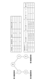
- FIG. 6 is a diagram for explaining a procedure for calculating the priority by the first priority calculation algorithm.
- the left side of FIG. 6 shows an example of machine element-control axis association information and each axis dependency information, and the right side of FIG. 6 shows various parameters calculated by the priority calculation unit 54b under such a configuration. It is a figure which shows.
- the machine tool has the first machine element, the second machine element, the third machine element, and the fourth machine element as the first control axis, the second control axis, and the third control axis. It is possible to move along the fourth control axis and the fifth control axis.
- the first control axis, the third control axis, and the fourth control axis are straight axes
- the second control axis and the fifth control axis are rotation axes.
- the first to second control axes and the third to fifth control axes can be moved independently of each other.
- the second control axis is lower than the first control axis
- the fourth control axis and the fifth control axis are lower than the third control axis
- the fifth control axis is lower than the fourth control axis.
- the first machine element is associated with the first control axis
- the second machine element is associated with the second control axis
- the third machine element is associated with the third machine element. Is associated with the 4th control axis and the 4th machine element is associated with the 5th control axis. Further, in FIG.
- the axis movement amount of the first control axis is 4, the axis movement amount of the second control axis is 2, the axis movement amount of the third control axis is 3, and the fourth control axis has an axis movement amount of 3.
- An example is shown in the case where the axis movement amount is 1 and the axis movement amount of the 5th control axis is 3. That is, in the example of FIG. 6, the amount of axial movement of the straight axis increases in the order of the fourth control axis, the third control axis, and the first control axis, and the amount of axial movement of the rotary axis increases with respect to the second control axis and the second control axis. It increases in the order of the fifth control axis.
- the first mechanical element is associated with the first control axis, which is the linear axis
- the second mechanical element is associated with the second control axis, which is the rotary axis
- the third mechanical element is the linear axis. It is associated with a fourth control axis
- the fourth mechanical element is associated with a fifth control axis, which is the axis of rotation. That is, the second machine element and the fourth machine element are rotary machine elements associated with the rotary axis, and the first mechanical element and the third mechanical element are straight machine elements associated with the straight axis.
- the fourth machine element becomes the first place.
- the second machine element is in second place
- the first machine element is in third place
- the third machine element is in fourth place.
- the combination of the second and fourth machine elements becomes the first place, and the first and fourth machine elements
- the combination is in 2nd place
- the combination of 3rd and 4th machine elements is in 3rd place
- the combination of 1st and 2nd machine elements is in 4th place
- the combination of 2nd and 3rd machine elements is in 5th place
- the 1st place is the 6th place.
- the priority calculation unit 54b calculates the priority for a plurality of check target sets based on the axis movement amount vector of each control axis transmitted from the position / orientation calculation unit 35. More specifically, the priority calculation unit 54b uses the axis movement amount vector calculated for each control axis, so that the relative axis movement amount with respect to the axis pair configured by combining two of the plurality of control axes. Calculate the vector.
- the total number of control axes is M
- the total number of axis pairs is M (M-1) / 2.
- the relative axis movement amount with respect to the axis pair composed of the nth control axis and the mth control axis is vn-vm.
- the priority calculation unit 54b calculates the relative axis movement amount (that is, the norm of the relative axis movement amount vector) for all the axis pairs.
- the priority calculation unit 54b gives priority to each check target group including the combination of each axis pair and the machine element associated with the machine element-control axis association information in descending order from the axis pair having the largest calculated relative axis movement amount. Calculate the degree. That is, under the second priority calculation algorithm, the priority calculation unit 54b may interfere with the check target set including the combination of the machine elements associated with the axis pair having a large relative axis movement amount per unit time. Is judged to be high, and the priority of the check target group including such a combination of machine elements is increased.
- the dimension of the axis movement amount differs depending on whether the control axis is a straight axis or a rotation axis. Therefore, the relative axis movement amount vector dnm obtained by subtracting the axis movement amount vector vm from the axis movement amount vector vn is physically obtained when at least one of the nth control axis and the mth control axis is the rotation axis. It loses its meaning. Therefore, when the rotation axis is included in all the control axes, the priority is calculated under the above-mentioned first priority calculation algorithm for the check target set including the rotation machine element associated with this rotation axis. Then, the priority is calculated under the second priority calculation algorithm only for the check target set including only the straight-ahead machine element.
- FIG. 7 is a diagram for explaining a procedure for calculating the priority by the second priority calculation algorithm.
- the left side of FIG. 7 shows an example of machine element-control axis association information and each axis dependency information, and the right side of FIG. 7 shows various parameters calculated by the priority calculation unit 54b under such a configuration. It is a figure which shows.
- the machine tool has the first machine element, the second machine element, and the third machine element as the first control axis, the second control axis, the third control axis, and the fourth control axis. It is possible to move along. In the example on the left side of FIG. 7, it is assumed that the first control axis, the second control axis, the third control axis, and the fourth control axis are all linear axes. In the example of each axis dependency relationship illustrated on the left side of FIG. 7, the first to second control axes and the third to fourth control axes can be moved independently of each other.
- the second control axis is lower than the first control axis
- the fourth control axis is lower than the third control axis.
- the first machine element is associated with the first control axis
- the second machine element is associated with the second control axis
- the third machine element is associated with the third machine element. Is associated with the 4th control axis.
- the machine tool includes first to fourth control axes. Therefore, by combining two of the first to fourth control axes, the first and second control axes, the first and third control axes, the first and fourth control axes, the second and third control axes, and the first A total of six axis pairs of the second and fourth control axes and the third and fourth control axes can be configured. Further, in FIG. 7, the relative axis movement amount between the first control axis and the second control axis is 4, and the relative axis movement amount between the first control axis and the third control axis is 5.
- the relative axis movement amount between the first control axis and the fourth control axis is 3, the relative axis movement amount between the second control axis and the third control axis is 1, and the second control axis and the second control axis.
- An example is shown in which the relative axis movement amount between the 4 control axes is 6 and the relative axis movement amount between the 3rd control axis and the 4th control axis is 2. That is, in the example of FIG. 7, the second and third control axes, the third and fourth control axes, the first and fourth control axes, the first and second control axes, the first and third control axes, and the first The relative axis movement amount increases in the order of the second and fourth control axes.
- the first and fourth control axes are associated with a combination of first and third machine elements
- the first and second control axes are associated with a combination of first and second machine elements
- 2nd and 4th control axes are associated with a combination of 2nd and 3rd machine elements. Therefore, when the priority for each check target group including the combination of each axis pair and the machine element associated with the machine element-control axis association information is calculated in descending order from the axis pair with the largest relative axis movement amount, the second and third The combination of machine elements is in first place, the combination of first and second machine elements is in second place, and the combination of first and third machine elements is in third place.
- the priority calculation unit 54b performs a plurality of checks based on the axis movement amount vector of each control axis and the pre-movement position vector of each machine element transmitted from the position / orientation calculation unit 35. Calculate the priority for the target set. More specifically, the priority calculation unit 54b is a check target based on the axis movement amount vector of each control axis, the pre-movement position vector of each machine element, and the machine element-control axis association information. A reduction rate parameter proportional to the reduction rate of the distance between the two machine elements constituting the set is calculated, and the priority for each check target set is calculated based on these reduction rate parameters.
- the priority calculation unit 54b acquires the axis movement amount vector of each control axis transmitted from the position / orientation calculation unit 35, and based on these axis movement amount vectors, each control axis is based on the machine element-control axis association information. Calculate the speed vector of the machine element associated with.
- the axis movement amount vector is used as it is as the velocity vector.
- the outer product of the axis movement amount vector and the predetermined moving diameter vector is used as the velocity vector.
- the radius vector used is predetermined for each rotation axis. More specifically, the direction of the radial vector is the radial direction orthogonal to the axis of rotation, and the norm of the radial vector is the distance along the radial direction from the axis of rotation to the machine element.
- the priority calculation unit 54b acquires the pre-movement position vector of each machine element transmitted from the position / orientation calculation unit 35, and based on these pre-movement position vectors, the two machine elements constituting each check target set. Calculate the normalized relative position vector for.
- the pre-movement position vector of the nth machine element is rn
- the pre-movement position vector of the mth machine element is rm
- the normalized relative position vector for the combination of the nth machine element and the m machine element is , (Rn-rm) /
- the priority calculation unit 54b calculates the relative velocity vector for the two machine elements constituting each check target set based on the velocity vector for each machine element calculated earlier.
- the velocity vector of the nth machine element is vn and the velocity vector of the mth machine element is vm
- the relative velocity vector for the combination of the nth machine element and the m machine element is vn-vm.
- the priority calculation unit 54b calculates the reduction rate parameter for each check target set by multiplying the inner product of the relative velocity vector and the relative position vector calculated earlier by a negative sign.
- the reduction rate parameters are ⁇ (vn-vm) ⁇ (rn-rm) /
- the reduction rate parameter calculated by the above procedure is proportional to the reduction rate per unit time of the distance between the two machine elements.
- the reduction rate parameter becomes 0, and if the distance between the two machine elements changes in the direction of increasing, the reduction rate parameter becomes negative and the two machine elements If the distance between them changes in the direction of becoming closer, the reduction rate parameter becomes positive.
- the priority calculation unit 54b calculates the priority in descending order from the check target group including the combination of the machine elements having the large reduction rate parameter calculated by the above procedure. That is, under the third priority calculation algorithm, the priority calculation unit 54b determines that there is a high possibility of interference in the check target set in which the reduction rate of the distance between the two components is large, and such a machine. Increase the priority of the set to be checked including the combination of elements.
- FIG. 8 is a diagram for explaining a procedure for calculating the priority by the third priority calculation algorithm.
- the left side of FIG. 8 shows an example of machine element-control axis association information and each axis dependency information
- the right side of FIG. 8 shows various parameters calculated by the priority calculation unit 54b under such a configuration. It is a figure which shows. Since the machine tool configuration shown on the left side of FIG. 8 is the same as that shown on the left side of FIG. 7, detailed description thereof will be omitted.
- the velocity vector of the first machine element associated with the first control axis is v1
- the velocity vector of the second machine element associated with the second control axis is v2
- the fourth is associated with the fourth control axis.
- the speed vector of the machine element is v3, the pre-movement position vector of the first machine element is r1, the pre-movement position vector of the second machine element is r2, and the pre-movement position vector of the third machine element is r3.
- the relative velocity vector v1-v2 for the combination of the first and second machine elements is (0,0,1)
- the relative velocity vector v1-v3 for the combination of the first and third machine elements is.
- the relative velocity vector v2-v3 for the combination of the second and third machine elements is (1,0,0), and the normalized relative to the combination of the first and second machine elements.
- the position vector r1-r2 is (0,0, -1) and the normalized relative position vector r1-r3 for the combination of the first and third machine elements is (0,0,1), the second and second. 3
- the normalized relative position vector r2-r3 for the combination of machine elements is (1,0,0).
- the reduction rate parameter for each combination of machine elements is calculated according to the above procedure, the reduction rate parameter for the combination of the first and second machine elements is 1, and the reduction rate parameter for the combination of the first and third machine elements is 0. Therefore, the reduction rate parameter for the combination of the second and third machine elements is -1. Therefore, when the priority is calculated in descending order from the check target group including the combination of machine elements with a large reduction rate parameter, the combination of the first and second machine elements is ranked first, and the combination of the first and third machine elements is ranked second. Therefore, the combination of the second and third machine elements is ranked third.
- the priority calculation unit 54b has the first to third priority calculation algorithms as described above for the plurality of check target groups extracted by the check target group extraction process in the check target group extraction unit 54a.
- the priority is calculated based on the priority calculation algorithm of any of the above or a combination thereof, and the calculated priority is added to the check target group list in the third storage unit 53. As a result, priority is given to the plurality of check target sets extracted by the check target set extraction unit 54a.
- the interference check support device 5 extracts the set to be checked from all the combinations of the plurality of machine elements based on the axis movement amount vector and the pre-movement position vector transmitted from the position / orientation calculation unit 35. Further, priorities are given to these plurality of check target groups, and the check target group list to which the priorities are given is stored in the third storage unit 53 as interference check support information (see, for example, FIG. 9).
- the interference check unit 36 acquires the post-movement position vector and post-movement posture information transmitted from the position / attitude calculation unit 35 for each interpolation cycle, and the interference check support information stored in the third storage unit 53. Further, the interference check unit 36 performs an interference check operation on a plurality of check target sets defined by the acquired interference check support information in order from the check target set having the highest priority.
- the check target set extraction unit 54a associates the moving pulse in the numerical control device 3 with each control axis in the machine tool 2 and the machine element moving along the control axis among the plurality of machine elements-control axis string.
- Extract the check target set of This checks all combinations of multiple machine elements, except for combinations of machine elements that are self-evidently non-interfering (eg, combinations of machine elements that move together along a control axis based on a moving pulse).
- the target set can be extracted.
- the numerical control device 3 moves a plurality of machine elements along a plurality of control axes based on the movement pulse, and performs an interference check operation on the check target set extracted by the check target set extraction unit 54a.
- the set to be checked for performing the interference check calculation can be narrowed down to only the combinations of machine elements that are not obvious to not interfere, so that the interference check calculation in the numerical control device 3 is performed for all combinations. It can be completed in a shorter time than in the case.
- the check target set extraction unit 54a specifies the control axis to be moved based on the movement pulse as the movement control axis, and based on the machine element-control axis association information and each axis dependency information, the movement control axis and its subordinates.
- the machine elements associated with the control axis of are classified into the dependent machine element group, the machine elements that do not belong to the dependent machine element group among all the machine elements are classified into the stationary machine element group, and each machine belonging to the dependent machine element group is classified.
- the set to be checked is extracted by combining the element and each machine element belonging to the stationary machine element group. As a result, the check target set for which the interference check calculation is performed can be narrowed down to only the combinations of machine elements that are not obvious to interfere with each other by a simple calculation.
- the check target set extraction unit 54a extracts the union of the combinations of machine elements under each movement control axis as the check target set. As a result, even when the machine element is moved along a plurality of control axes at the same time, the set to be checked can be appropriately narrowed down.
- the check target group extraction unit 54a stores the extracted information about the check target group in the third storage unit 53 as interference check support information, and the interference check unit 36 stores the interference check support information stored in the third storage unit 53. Refer to it and perform the interference check calculation. As a result, the check target set extraction unit 54a can perform an operation of extracting the check target set at a free timing independent of the interference check calculation in the interference check unit 36.
- the interference check support device 5 having a function of generating interference check support information is incorporated into the numerical control device 3 that controls the machine tool 2 and performs the interference check calculation, and the interference check support device 5 has a numerical value.
- Interference check support information is generated based on the moving pulse transmitted from the pulse generation unit 34 of the control device 3.
- the calculation load on the numerical control device 3 becomes large, it is possible to generate interference check support information in real time while controlling the machine tool 2 by the numerical control device 3. Therefore, for example, even when the machine tool 2 is manually operated by an operator, appropriate interference check support information can be generated.
- FIG. 10 is a schematic diagram of the numerical control system 1A according to the present embodiment.
- the numerical control system 1A according to the present embodiment relates to the first embodiment in that it includes a numerical control device 3A and an interference check support device 5A configured separately from the numerical control device 3A. It is different from the numerical control system 1A.
- the interference check support device 5A includes a first storage unit 51, a second storage unit 52, a check support information generation unit 54, and a movement amount position calculation unit 55A.
- the movement amount position calculation unit 55A reads out the numerical control program stored in the machining program memory 31, and performs calculations in the command analysis unit 32, the interpolation unit 33, the pulse generation unit 34, and the position / attitude calculation unit 35 of the numerical control device 3. By the same procedure, the axis movement amount vector of each control axis and the pre-movement position vector of each machine element are generated in the same cycle as the interpolation cycle in the numerical control device 3.
- the movement amount position calculation unit 55A transmits the generated axis movement amount vector and the pre-movement position vector to the check support information generation unit 54.
- the procedure for generating interference check support information in the check support information generation unit 54 based on the axis movement amount vector and the pre-movement position vector transmitted from the movement amount position calculation unit 55A is the same as that in the first embodiment. The explanation is omitted.
- the interference check support device 5A that generates interference check support information based on the numerical control program stored in the machining program memory 31 is configured separately from the numerical control device 3A. Thereby, before starting the control of the machine tool 2 by the numerical control device 3A, more specifically, at the stage where the numerical control program is created, the interference check support information can be generated based on this numerical control program. .. Therefore, according to the numerical control system 1 according to the present embodiment, it is possible to reduce the calculation load of the numerical control device 3A when controlling the machine tool 2 as compared with the numerical control system 1 according to the first embodiment. can.
- the check support information generation unit 54 stores the generated check support information in the third storage unit 53, and the interference check unit 36 reads the check support information stored in the third storage unit 53.
- the case where the interference check calculation is performed has been described above, but the present invention is not limited to this.
- the check support information generated by the check support information generation unit 54 may be transmitted to the interference check unit 36 without going through the third storage unit 53.
Landscapes
- Engineering & Computer Science (AREA)
- Human Computer Interaction (AREA)
- Manufacturing & Machinery (AREA)
- Physics & Mathematics (AREA)
- General Physics & Mathematics (AREA)
- Automation & Control Theory (AREA)
- Numerical Control (AREA)
Abstract
Description
以下、図面を参照して、本開示の第1実施形態に係る数値制御システムについて説明する。
第1の優先度算出アルゴリズムの下では、優先度算出部54bは、位置姿勢算出部35から送信される各制御軸の軸移動量に基づいて複数のチェック対象組に対する優先度を算出する。より具体的には、優先度算出部54bは、軸移動量が大きい制御軸から降順で、各制御軸と機械要素-制御軸紐付け情報によって関連付けられる各機械要素に対する機械要素順位を算出する。次に優先度算出部54bは、算出した機械要素順位が高い機械要素から降順で、各機械要素を含むチェック対象組に対する優先度を算出する。すなわち第1の優先度算出アルゴリズムの下では、優先度算出部54bは、単位時間当たりの軸移動量が大きな制御軸と関連付けられている機械要素を含むチェック対象組において干渉する可能性が高いと判断し、このような機械要素を含むチェック対象組の優先度を高くする。
第2の優先度算出アルゴリズムの下では、優先度算出部54bは、位置姿勢算出部35から送信される各制御軸の軸移動量ベクトルに基づいて複数のチェック対象組に対する優先度を算出する。より具体的には、優先度算出部54bは、制御軸毎に算出された軸移動量ベクトルを用いることによって、複数の制御軸のうち2つを組み合わせて構成される軸対に対する相対軸移動量ベクトルを算出する。ここで制御軸の総数がMである場合、軸対の総数はM(M-1)/2である。また例えば第n制御軸の軸移動量ベクトルをvnとし、第m制御軸の軸移動量ベクトルをvmとした場合、第n制御軸及び第m制御軸によって構成される軸対に対する相対軸移動量ベクトルdnmは、vn-vmとなる。
第3の優先度算出アルゴリズムの下では、優先度算出部54bは、位置姿勢算出部35から送信される各制御軸の軸移動量ベクトル及び各機械要素の移動前位置ベクトルに基づいて複数のチェック対象組に対する優先度を算出する。より具体的には、優先度算出部54bは、各制御軸の軸移動量ベクトルと、各機械要素の移動前位置ベクトルと、機械要素-制御軸紐付け情報と、に基づいて、各チェック対象組を構成する2つの機械要素の間の距離の減少率に比例する減少率パラメータを算出し、これら減少率パラメータに基づいて各チェック対象組に対する優先度を算出する。
チェック対象組抽出部54aは、数値制御装置3における移動パルスと、工作機械2における各制御軸と複数の機械要素のうちこの制御軸に沿って移動する機械要素とを関連付ける機械要素-制御軸紐付け情報と、工作機械2における各制御軸の間の従属関係を規定する各軸従属関係情報と、に基づいて、工作機械2を構成する複数の機械要素の全ての組み合わせの中から1組以上のチェック対象組を抽出する。これにより、複数の機械要素の全ての組み合わせの中から、干渉しないことが自明な機械要素の組み合わせ(例えば、移動パルスに基づく制御軸に沿って一緒に移動する機械要素の組み合わせ)を除いてチェック対象組を抽出することができる。また数値制御装置3は、移動パルスに基づいて複数の機械要素を複数の制御軸に沿って移動させるとともに、チェック対象組抽出部54aによって抽出されたチェック対象組について干渉チェック演算を行う。本実施形態によれば、干渉チェック演算を行うチェック対象組を、干渉しないことが非自明な機械要素の組み合わせのみに絞り込むことができるので、数値制御装置3における干渉チェック演算を全ての組み合わせについて行う場合よりも短時間で終えることができる。
次に、本開示の第2実施形態に係る数値制御システムについて説明する。なお以下の説明では、第1実施形態に係る数値制御システムと同じ構成については同じ符号を付し、詳細な説明を省略する。
2…工作機械
3,3A…数値制御装置
31…加工プログラムメモリ
32…指令解析部
33…補間部
34…パルス生成部
35…位置姿勢算出部
36…干渉チェック部
37…形状記憶部
5,5A…干渉チェック支援装置
51…第1記憶部
52…第2記憶部
53…第3記憶部
54…チェック支援情報生成部
54a…チェック対象組抽出部
54b…優先度算出部
55A…移動量位置算出部
Claims (6)
- 移動指令に基づいて工作機械の複数の機械要素を複数の軸に沿って移動させるとともに所定のチェック対象組によって組み合わせられる2つの機械要素の間の干渉チェック演算を行う数値制御装置と、
前記干渉チェック演算を支援する干渉チェック支援装置と、を備える数値制御システムであって、
前記干渉チェック支援装置は、
前記工作機械における各軸と前記複数の機械要素のうち当該軸に沿って移動する機械要素とを関連付ける第1情報を記憶する第1記憶部と、
前記工作機械における各軸の間の従属関係を規定する第2情報を記憶する第2記憶部と、
前記移動指令、前記第1情報、及び前記第2情報に基づいて、前記複数の機械要素の全ての組み合わせの中から1組以上の前記チェック対象組を抽出するチェック対象組抽出部と、を備える、数値制御システム。 - 前記チェック対象組抽出部は、
前記移動指令に基づいて移動させる軸を移動軸として特定し、
前記第1情報及び前記第2情報に基づいて、前記移動軸及び当該移動軸より下位の軸と関連付けられた機械要素を従属機械要素群に分類し、
全ての機械要素のうち前記従属機械要素群に属しない機械要素を静止機械要素群に分類し、
前記従属機械要素群に属する各機械要素と前記静止機械要素群に属する各機械要素とを組み合わせることによって前記チェック対象組を抽出する、請求項1に記載の数値制御システム。 - 前記チェック対象組抽出部は、前記移動軸が複数存在する場合、各移動軸の下における機械要素の組み合わせの和集合を前記チェック対象組として抽出する、請求項2に記載の数値制御システム。
- 前記チェック対象組抽出部によって抽出された前記チェック対象組に関する情報を記憶する第3記憶部をさらに備え、
前記数値制御装置は、前記第3記憶部に記憶された前記チェック対象組に関する情報を参照し、前記干渉チェック演算を行う、請求項1から3の何れかに記載の数値制御システム。 - 前記第2記憶部には、前記第2情報が機械構成木形式で記憶されている、請求項1から4の何れかに記載の数値制御システム。
- 移動指令に基づいて工作機械の複数の機械要素を複数の軸に沿って移動させるとともにチェック対象組によって組み合わせられた2つの機械要素の間の干渉チェック演算を行う数値制御装置における前記干渉チェック演算を支援する干渉チェック支援方法であって、
前記移動指令と、前記工作機械における各軸と前記複数の機械要素のうち当該軸に沿って移動する機械要素とを関連付ける第1情報と、前記工作機械における各軸の間の従属関係を規定する第2情報と、を取得し、
前記移動指令と前記第1情報と前記第2情報とに基づいて、前記複数の機械要素の全ての組み合わせの中から1組以上の前記チェック対象組を抽出する、干渉チェック支援方法。
Priority Applications (4)
| Application Number | Priority Date | Filing Date | Title |
|---|---|---|---|
| DE112021004588.1T DE112021004588T5 (de) | 2020-08-31 | 2021-08-26 | Numerisches Steuersystem und ein Verfahren zur Unterstützung der Interferenzkontrolle |
| US18/041,060 US12607978B2 (en) | 2020-08-31 | 2021-08-26 | Numerical control system and interference checking assistance method |
| CN202180052480.4A CN115885225B (zh) | 2020-08-31 | 2021-08-26 | 数值控制系统及干扰检查辅助方法 |
| JP2022545702A JP7513725B2 (ja) | 2020-08-31 | 2021-08-26 | 数値制御システム及び干渉チェック支援方法 |
Applications Claiming Priority (2)
| Application Number | Priority Date | Filing Date | Title |
|---|---|---|---|
| JP2020-146207 | 2020-08-31 | ||
| JP2020146207 | 2020-08-31 |
Publications (1)
| Publication Number | Publication Date |
|---|---|
| WO2022045253A1 true WO2022045253A1 (ja) | 2022-03-03 |
Family
ID=80353415
Family Applications (1)
| Application Number | Title | Priority Date | Filing Date |
|---|---|---|---|
| PCT/JP2021/031376 Ceased WO2022045253A1 (ja) | 2020-08-31 | 2021-08-26 | 数値制御システム及び干渉チェック支援方法 |
Country Status (5)
| Country | Link |
|---|---|
| US (1) | US12607978B2 (ja) |
| JP (1) | JP7513725B2 (ja) |
| CN (1) | CN115885225B (ja) |
| DE (1) | DE112021004588T5 (ja) |
| WO (1) | WO2022045253A1 (ja) |
Cited By (1)
| Publication number | Priority date | Publication date | Assignee | Title |
|---|---|---|---|---|
| JP2022041159A (ja) * | 2020-08-31 | 2022-03-11 | ファナック株式会社 | 数値制御システム及び干渉チェック方法 |
Families Citing this family (1)
| Publication number | Priority date | Publication date | Assignee | Title |
|---|---|---|---|---|
| CN116113896B (zh) * | 2020-08-31 | 2025-10-28 | 发那科株式会社 | 数值控制系统 |
Citations (3)
| Publication number | Priority date | Publication date | Assignee | Title |
|---|---|---|---|---|
| JPH0683422A (ja) * | 1992-03-10 | 1994-03-25 | Mitsubishi Electric Corp | 数値制御方法 |
| JP2000284819A (ja) * | 1999-01-27 | 2000-10-13 | Mitsubishi Electric Corp | 数値制御工作機械における干渉検出方法および数値制御装置 |
| JP2019057262A (ja) * | 2016-12-12 | 2019-04-11 | ファナック株式会社 | 制御装置及びデータ構造 |
Family Cites Families (10)
| Publication number | Priority date | Publication date | Assignee | Title |
|---|---|---|---|---|
| JP3563191B2 (ja) | 1996-02-26 | 2004-09-08 | 三菱電機株式会社 | 数値制御装置 |
| JPH10232706A (ja) * | 1997-02-20 | 1998-09-02 | Toyota Motor Corp | Nc工作機械用干渉チェック方法 |
| JP2005128686A (ja) * | 2003-10-22 | 2005-05-19 | Fanuc Ltd | 数値制御装置 |
| JP4904731B2 (ja) * | 2005-07-06 | 2012-03-28 | 株式会社ジェイテクト | 工作機械の干渉チェック装置 |
| JP6066041B2 (ja) | 2012-07-17 | 2017-01-25 | 三菱日立パワーシステムズ株式会社 | 加工支援装置および加工支援システム |
| JP6209392B2 (ja) * | 2013-08-12 | 2017-10-04 | Dmg森精機株式会社 | 干渉確認装置 |
| JP6166300B2 (ja) * | 2015-04-13 | 2017-07-19 | ファナック株式会社 | 工具と被加工物の干渉チェックが可能な数値制御装置 |
| US11402818B2 (en) * | 2016-12-12 | 2022-08-02 | Fanuc Corporation | Numerical controller and data structure |
| WO2019043852A1 (ja) * | 2017-08-30 | 2019-03-07 | 三菱電機株式会社 | 数値制御システムおよびモータ制御装置 |
| JP7505877B2 (ja) * | 2019-12-02 | 2024-06-25 | ファナック株式会社 | 制御システム |
-
2021
- 2021-08-26 JP JP2022545702A patent/JP7513725B2/ja active Active
- 2021-08-26 US US18/041,060 patent/US12607978B2/en active Active
- 2021-08-26 WO PCT/JP2021/031376 patent/WO2022045253A1/ja not_active Ceased
- 2021-08-26 DE DE112021004588.1T patent/DE112021004588T5/de active Pending
- 2021-08-26 CN CN202180052480.4A patent/CN115885225B/zh active Active
Patent Citations (3)
| Publication number | Priority date | Publication date | Assignee | Title |
|---|---|---|---|---|
| JPH0683422A (ja) * | 1992-03-10 | 1994-03-25 | Mitsubishi Electric Corp | 数値制御方法 |
| JP2000284819A (ja) * | 1999-01-27 | 2000-10-13 | Mitsubishi Electric Corp | 数値制御工作機械における干渉検出方法および数値制御装置 |
| JP2019057262A (ja) * | 2016-12-12 | 2019-04-11 | ファナック株式会社 | 制御装置及びデータ構造 |
Cited By (2)
| Publication number | Priority date | Publication date | Assignee | Title |
|---|---|---|---|---|
| JP2022041159A (ja) * | 2020-08-31 | 2022-03-11 | ファナック株式会社 | 数値制御システム及び干渉チェック方法 |
| JP7560294B2 (ja) | 2020-08-31 | 2024-10-02 | ファナック株式会社 | 数値制御システム及び干渉チェック方法 |
Also Published As
| Publication number | Publication date |
|---|---|
| US12607978B2 (en) | 2026-04-21 |
| US20230288903A1 (en) | 2023-09-14 |
| CN115885225B (zh) | 2025-09-12 |
| JPWO2022045253A1 (ja) | 2022-03-03 |
| DE112021004588T5 (de) | 2023-06-22 |
| CN115885225A (zh) | 2023-03-31 |
| JP7513725B2 (ja) | 2024-07-09 |
Similar Documents
| Publication | Publication Date | Title |
|---|---|---|
| CA2784720C (en) | Predictive control and visualizing system for a nc machine tool | |
| JP6450732B2 (ja) | 数値制御装置 | |
| Bakker et al. | Active fixturing: literature review and future research directions | |
| JP2015202537A (ja) | 力に応じて動かすロボットのロボット制御装置およびロボットシステム | |
| WO2011096327A1 (ja) | 加工経路生成方法及びその装置 | |
| CN105320059B (zh) | 伺服电动机的控制装置 | |
| JP2013058035A (ja) | ワーク設置誤差補正部を有する多軸工作機械用数値制御装置 | |
| CN107577882A (zh) | 一种侧铣直纹曲面的表面形貌建模及成型的仿真方法 | |
| KR102312368B1 (ko) | 여자유도 로봇 제어 시스템, 방법, 및 상기 방법을 실행시키기 위한 컴퓨터 판독 가능한 프로그램을 기록한 기록 매체 | |
| JP2013257809A (ja) | 工作機械の工具ベクトルを表示する工具軌跡表示装置 | |
| WO2022045253A1 (ja) | 数値制御システム及び干渉チェック支援方法 | |
| JP2015202534A (ja) | 力に応じて動かすロボットのロボット制御装置およびロボットシステム | |
| US8521322B2 (en) | Automatic programming method and device for creating multi-path program | |
| CN101791810B (zh) | 极坐标数控木工篓铣机 | |
| JPWO2014196066A1 (ja) | 数値制御装置 | |
| Wavering | Parallel kinematic machine research at NIST: Past, present, and future | |
| Yuen et al. | Trajectory generation and control of a 9 axis CNC micromachining center | |
| JP2022041159A (ja) | 数値制御システム及び干渉チェック方法 | |
| CN109143981A (zh) | 计算机可读取的信息记录介质、评价方法以及控制装置 | |
| Owen et al. | Stiffness optimization for two‐armed robotic sculpting | |
| JP2022113180A (ja) | 工作機械支援装置 | |
| Rajput et al. | Comparative study of CNC Controllers used in CNC Milling Machine | |
| JP7131454B2 (ja) | 数値制御装置、工作機械、制御プログラム、及び記憶媒体 | |
| Maťuga | Control and positioning of robotic arm on CNC cutting machines and their applications in industry | |
| JP7448667B2 (ja) | 数値制御システム |
Legal Events
| Date | Code | Title | Description |
|---|---|---|---|
| 121 | Ep: the epo has been informed by wipo that ep was designated in this application |
Ref document number: 21861675 Country of ref document: EP Kind code of ref document: A1 |
|
| ENP | Entry into the national phase |
Ref document number: 2022545702 Country of ref document: JP Kind code of ref document: A |
|
| 122 | Ep: pct application non-entry in european phase |
Ref document number: 21861675 Country of ref document: EP Kind code of ref document: A1 |
|
| WWG | Wipo information: grant in national office |
Ref document number: 202180052480.4 Country of ref document: CN |