WO2022044606A1 - 医療画像処理装置、医療画像処理方法、内視鏡システム、及び医療画像処理プログラム - Google Patents
医療画像処理装置、医療画像処理方法、内視鏡システム、及び医療画像処理プログラム Download PDFInfo
- Publication number
- WO2022044606A1 WO2022044606A1 PCT/JP2021/026720 JP2021026720W WO2022044606A1 WO 2022044606 A1 WO2022044606 A1 WO 2022044606A1 JP 2021026720 W JP2021026720 W JP 2021026720W WO 2022044606 A1 WO2022044606 A1 WO 2022044606A1
- Authority
- WO
- WIPO (PCT)
- Prior art keywords
- state
- interest
- image processing
- medical image
- region
- Prior art date
- Legal status (The legal status is an assumption and is not a legal conclusion. Google has not performed a legal analysis and makes no representation as to the accuracy of the status listed.)
- Ceased
Links
Images


Classifications
-
- A—HUMAN NECESSITIES
- A61—MEDICAL OR VETERINARY SCIENCE; HYGIENE
- A61B—DIAGNOSIS; SURGERY; IDENTIFICATION
- A61B34/00—Computer-aided surgery; Manipulators or robots specially adapted for use in surgery
- A61B34/20—Surgical navigation systems; Devices for tracking or guiding surgical instruments, e.g. for frameless stereotaxis
-
- A—HUMAN NECESSITIES
- A61—MEDICAL OR VETERINARY SCIENCE; HYGIENE
- A61B—DIAGNOSIS; SURGERY; IDENTIFICATION
- A61B1/00—Instruments for performing medical examinations of the interior of cavities or tubes of the body by visual or photographical inspection, e.g. endoscopes; Illuminating arrangements therefor
- A61B1/00002—Operational features of endoscopes
- A61B1/00004—Operational features of endoscopes characterised by electronic signal processing
- A61B1/00009—Operational features of endoscopes characterised by electronic signal processing of image signals during a use of endoscope
- A61B1/000094—Operational features of endoscopes characterised by electronic signal processing of image signals during a use of endoscope extracting biological structures
-
- A—HUMAN NECESSITIES
- A61—MEDICAL OR VETERINARY SCIENCE; HYGIENE
- A61B—DIAGNOSIS; SURGERY; IDENTIFICATION
- A61B1/00—Instruments for performing medical examinations of the interior of cavities or tubes of the body by visual or photographical inspection, e.g. endoscopes; Illuminating arrangements therefor
- A61B1/00002—Operational features of endoscopes
- A61B1/00043—Operational features of endoscopes provided with output arrangements
- A61B1/00045—Display arrangement
- A61B1/0005—Display arrangement combining images e.g. side-by-side, superimposed or tiled
-
- A—HUMAN NECESSITIES
- A61—MEDICAL OR VETERINARY SCIENCE; HYGIENE
- A61B—DIAGNOSIS; SURGERY; IDENTIFICATION
- A61B1/00—Instruments for performing medical examinations of the interior of cavities or tubes of the body by visual or photographical inspection, e.g. endoscopes; Illuminating arrangements therefor
- A61B1/012—Instruments for performing medical examinations of the interior of cavities or tubes of the body by visual or photographical inspection, e.g. endoscopes; Illuminating arrangements therefor characterised by internal passages or accessories therefor
- A61B1/018—Instruments for performing medical examinations of the interior of cavities or tubes of the body by visual or photographical inspection, e.g. endoscopes; Illuminating arrangements therefor characterised by internal passages or accessories therefor for receiving instruments
-
- A—HUMAN NECESSITIES
- A61—MEDICAL OR VETERINARY SCIENCE; HYGIENE
- A61B—DIAGNOSIS; SURGERY; IDENTIFICATION
- A61B1/00—Instruments for performing medical examinations of the interior of cavities or tubes of the body by visual or photographical inspection, e.g. endoscopes; Illuminating arrangements therefor
- A61B1/04—Instruments for performing medical examinations of the interior of cavities or tubes of the body by visual or photographical inspection, e.g. endoscopes; Illuminating arrangements therefor combined with photographic or television appliances
- A61B1/045—Control thereof
-
- A—HUMAN NECESSITIES
- A61—MEDICAL OR VETERINARY SCIENCE; HYGIENE
- A61B—DIAGNOSIS; SURGERY; IDENTIFICATION
- A61B1/00—Instruments for performing medical examinations of the interior of cavities or tubes of the body by visual or photographical inspection, e.g. endoscopes; Illuminating arrangements therefor
- A61B1/06—Instruments for performing medical examinations of the interior of cavities or tubes of the body by visual or photographical inspection, e.g. endoscopes; Illuminating arrangements therefor with illuminating arrangements
- A61B1/0638—Instruments for performing medical examinations of the interior of cavities or tubes of the body by visual or photographical inspection, e.g. endoscopes; Illuminating arrangements therefor with illuminating arrangements providing two or more wavelengths
-
- G—PHYSICS
- G06—COMPUTING OR CALCULATING; COUNTING
- G06T—IMAGE DATA PROCESSING OR GENERATION, IN GENERAL
- G06T7/00—Image analysis
- G06T7/10—Segmentation; Edge detection
- G06T7/11—Region-based segmentation
-
- G—PHYSICS
- G06—COMPUTING OR CALCULATING; COUNTING
- G06V—IMAGE OR VIDEO RECOGNITION OR UNDERSTANDING
- G06V10/00—Arrangements for image or video recognition or understanding
- G06V10/20—Image preprocessing
- G06V10/25—Determination of region of interest [ROI] or a volume of interest [VOI]
-
- G—PHYSICS
- G06—COMPUTING OR CALCULATING; COUNTING
- G06V—IMAGE OR VIDEO RECOGNITION OR UNDERSTANDING
- G06V10/00—Arrangements for image or video recognition or understanding
- G06V10/40—Extraction of image or video features
- G06V10/44—Local feature extraction by analysis of parts of the pattern, e.g. by detecting edges, contours, loops, corners, strokes or intersections; Connectivity analysis, e.g. of connected components
- G06V10/443—Local feature extraction by analysis of parts of the pattern, e.g. by detecting edges, contours, loops, corners, strokes or intersections; Connectivity analysis, e.g. of connected components by matching or filtering
- G06V10/449—Biologically inspired filters, e.g. difference of Gaussians [DoG] or Gabor filters
- G06V10/451—Biologically inspired filters, e.g. difference of Gaussians [DoG] or Gabor filters with interaction between the filter responses, e.g. cortical complex cells
- G06V10/454—Integrating the filters into a hierarchical structure, e.g. convolutional neural networks [CNN]
-
- G—PHYSICS
- G06—COMPUTING OR CALCULATING; COUNTING
- G06V—IMAGE OR VIDEO RECOGNITION OR UNDERSTANDING
- G06V10/00—Arrangements for image or video recognition or understanding
- G06V10/70—Arrangements for image or video recognition or understanding using pattern recognition or machine learning
- G06V10/82—Arrangements for image or video recognition or understanding using pattern recognition or machine learning using neural networks
-
- G—PHYSICS
- G06—COMPUTING OR CALCULATING; COUNTING
- G06V—IMAGE OR VIDEO RECOGNITION OR UNDERSTANDING
- G06V10/00—Arrangements for image or video recognition or understanding
- G06V10/94—Hardware or software architectures specially adapted for image or video understanding
- G06V10/945—User interactive design; Environments; Toolboxes
-
- G—PHYSICS
- G16—INFORMATION AND COMMUNICATION TECHNOLOGY [ICT] SPECIALLY ADAPTED FOR SPECIFIC APPLICATION FIELDS
- G16H—HEALTHCARE INFORMATICS, i.e. INFORMATION AND COMMUNICATION TECHNOLOGY [ICT] SPECIALLY ADAPTED FOR THE HANDLING OR PROCESSING OF MEDICAL OR HEALTHCARE DATA
- G16H30/00—ICT specially adapted for the handling or processing of medical images
- G16H30/20—ICT specially adapted for the handling or processing of medical images for handling medical images, e.g. DICOM, HL7 or PACS
-
- G—PHYSICS
- G16—INFORMATION AND COMMUNICATION TECHNOLOGY [ICT] SPECIALLY ADAPTED FOR SPECIFIC APPLICATION FIELDS
- G16H—HEALTHCARE INFORMATICS, i.e. INFORMATION AND COMMUNICATION TECHNOLOGY [ICT] SPECIALLY ADAPTED FOR THE HANDLING OR PROCESSING OF MEDICAL OR HEALTHCARE DATA
- G16H30/00—ICT specially adapted for the handling or processing of medical images
- G16H30/40—ICT specially adapted for the handling or processing of medical images for processing medical images, e.g. editing
-
- A—HUMAN NECESSITIES
- A61—MEDICAL OR VETERINARY SCIENCE; HYGIENE
- A61B—DIAGNOSIS; SURGERY; IDENTIFICATION
- A61B1/00—Instruments for performing medical examinations of the interior of cavities or tubes of the body by visual or photographical inspection, e.g. endoscopes; Illuminating arrangements therefor
- A61B1/00002—Operational features of endoscopes
- A61B1/00004—Operational features of endoscopes characterised by electronic signal processing
- A61B1/00009—Operational features of endoscopes characterised by electronic signal processing of image signals during a use of endoscope
- A61B1/000096—Operational features of endoscopes characterised by electronic signal processing of image signals during a use of endoscope using artificial intelligence
-
- A—HUMAN NECESSITIES
- A61—MEDICAL OR VETERINARY SCIENCE; HYGIENE
- A61B—DIAGNOSIS; SURGERY; IDENTIFICATION
- A61B34/00—Computer-aided surgery; Manipulators or robots specially adapted for use in surgery
- A61B34/20—Surgical navigation systems; Devices for tracking or guiding surgical instruments, e.g. for frameless stereotaxis
- A61B2034/2046—Tracking techniques
- A61B2034/2055—Optical tracking systems
-
- A—HUMAN NECESSITIES
- A61—MEDICAL OR VETERINARY SCIENCE; HYGIENE
- A61B—DIAGNOSIS; SURGERY; IDENTIFICATION
- A61B34/00—Computer-aided surgery; Manipulators or robots specially adapted for use in surgery
- A61B34/20—Surgical navigation systems; Devices for tracking or guiding surgical instruments, e.g. for frameless stereotaxis
- A61B2034/2046—Tracking techniques
- A61B2034/2065—Tracking using image or pattern recognition
-
- A—HUMAN NECESSITIES
- A61—MEDICAL OR VETERINARY SCIENCE; HYGIENE
- A61B—DIAGNOSIS; SURGERY; IDENTIFICATION
- A61B90/00—Instruments, implements or accessories specially adapted for surgery or diagnosis and not covered by any of the groups A61B1/00 - A61B50/00, e.g. for luxation treatment or for protecting wound edges
- A61B90/30—Devices for illuminating a surgical field, the devices having an interrelation with other surgical devices or with a surgical procedure
- A61B2090/309—Devices for illuminating a surgical field, the devices having an interrelation with other surgical devices or with a surgical procedure using white LEDs
-
- G—PHYSICS
- G06—COMPUTING OR CALCULATING; COUNTING
- G06T—IMAGE DATA PROCESSING OR GENERATION, IN GENERAL
- G06T2207/00—Indexing scheme for image analysis or image enhancement
- G06T2207/10—Image acquisition modality
- G06T2207/10068—Endoscopic image
-
- G—PHYSICS
- G06—COMPUTING OR CALCULATING; COUNTING
- G06T—IMAGE DATA PROCESSING OR GENERATION, IN GENERAL
- G06T2207/00—Indexing scheme for image analysis or image enhancement
- G06T2207/30—Subject of image; Context of image processing
- G06T2207/30004—Biomedical image processing
- G06T2207/30096—Tumor; Lesion
-
- G—PHYSICS
- G06—COMPUTING OR CALCULATING; COUNTING
- G06V—IMAGE OR VIDEO RECOGNITION OR UNDERSTANDING
- G06V2201/00—Indexing scheme relating to image or video recognition or understanding
- G06V2201/03—Recognition of patterns in medical or anatomical images
- G06V2201/034—Recognition of patterns in medical or anatomical images of medical instruments
Definitions
- the present invention relates to a medical image processing apparatus, a medical image processing method, an endoscope system, and a medical image processing program.
- the endoscope system described in Patent Document 1 includes an image acquisition unit that acquires an image of a subject, a recognition unit that performs recognition processing that recognizes the subject using the image, and a discrimination unit that discriminates an operation on the subject. It also includes a setting unit for setting the recognition unit to be valid or invalid using the discrimination result of the discrimination unit, and a notification unit for notifying the valid or invalid state of the recognition unit.
- One embodiment of the present invention provides a medical image processing apparatus, a medical image processing method, an endoscopic system, and a medical image processing program capable of displaying an area of interest with appropriate discriminating power.
- the medical image processing apparatus is a medical image processing apparatus including a processor, and the processor recognizes an image acquisition process for acquiring an observation image of a subject and a region of interest from the observation image.
- the area of interest recognition process, the device information recognition process that recognizes the device information that is the information of the device used for the treatment of the subject from the observed image, and the discriminating power according to the recognition result of the device information in the observed image.
- a display control process for causing the display device to identify and display the image is performed.
- the medical image processing apparatus is the treatment state in which the processor is performing treatment on the region of interest by the instrument based on the instrument information in the instrument information recognition process, and preparation for treatment.
- the treatment state and the pre-treatment state are identified more than the non-treatment state by determining whether the state is a pre-treatment state, a treatment state, or a non-treatment state other than the pre-treatment state. The force is reduced to display the observation image.
- the processor displays the observation image in the treatment state with a lower discriminating power than in the pretreatment state.
- the medical image processing apparatus is the device, in which the device is inserted, the type of the inserted device, the length of the insertion, and the device in the device information recognition process.
- the treated, pre-treated, and untreated states based on the instrument information, including at least one of the operational state, the distance between the instrument and the area of interest, and whether the instrument and the area of interest overlap in the observation image. Determine which is which.
- the medical image processing apparatus is in any one of the second to fourth aspects, in which the processor observes the frame surrounding the region of interest in the treatment state and / or the pretreatment state in the display control process. Overlay on the image.
- the medical image processing apparatus is in any one of the second to fifth aspects, in which the processor displays a symbol indicating a region of interest in the observation image in the treatment state and the pretreatment state in the display control processing. Display in superimposition.
- the medical image processing apparatus is in any one of the second to sixth aspects, in which the processor becomes a part of the region of interest in the observed image in the treatment state and the pre-treatment state in the display control process. At least one of characters, figures, and symbols is superimposed and displayed.
- the medical image processing apparatus is the region of interest in any one of the second to eighth aspects, in the display control process, in the treated state and the pre-treatment state, as compared with the non-treated state.
- the observation image is displayed by changing the color and / or brightness of.
- the endoscope system includes a medical image processing device according to any one of the first to ninth aspects, a display device for displaying an observation image, and an endoscope inserted into a subject.
- the scope includes an endoscope scope having a photographing unit for photographing an observation image.
- the medical image processing method includes an image acquisition step of acquiring an observation image of a subject on a computer, an interest region recognition step of recognizing an interest region from the observation image, and a subject from the observation image.
- the instrument information recognition process for recognizing the instrument information, which is the information of the instrument used for the treatment, and the display for displaying the observation image on the display device in a manner in which the region of interest has discriminating power according to the recognition result of the instrument information. Let the control process be performed.
- the eleventh aspect and the medical image processing method according to each of the following aspects can also be grasped as an operation method of the medical image processing apparatus.
- the medical image processing method is the eleventh aspect, in which, in the instrument information recognition step, the treatment state in which the treatment is performed on the region of interest by the instrument based on the instrument information, and the treatment are prepared. It is made to judge whether it is a pre-treatment state, a treatment state, or a non-treatment state which is a state other than the pre-treatment state, and in the display control step, the treatment state and the pre-treatment state have more discriminating power than the non-treatment state.
- the observed image is displayed on the display device by lowering it.
- the medical image processing method is the twelfth aspect, in which in the display control step, in the treated state, the discriminating power is lowered as compared with the pre-treatment state, and the observed image is displayed.
- the medical image processing method is the twelfth or thirteenth aspect, in which the instrument is inserted, the type of the inserted instrument, the length of the insertion, the operating state of the instrument, and the like in the instrument information recognition step. It is either a treated state, a pretreatment state, or a non-treated state based on the device information including at least one of the distance between the device and the area of interest and whether or not the device and the area of interest overlap in the observation image. To judge.
- the medical image processing program according to the fifteenth aspect causes a computer to execute the medical image processing method according to any one of the eleventh to fourteenth aspects.
- a non-temporary recording medium on which a computer-readable code of the medical image processing program according to the fifteenth aspect is recorded can also be mentioned as one aspect of the present invention.
- FIG. 1 is an external view of the endoscope system according to the first embodiment.
- FIG. 2 is a block diagram showing a main configuration of an endoscope system.
- FIG. 3 is a functional block diagram of the image processing unit.
- FIG. 4 is a diagram showing the configuration of a convolutional neural network.
- FIG. 5 is a diagram showing a state of the convolution process by the filter.
- FIG. 6 is a flowchart showing the procedure of the medical image processing method according to the first embodiment.
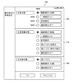
- FIG. 7 is a diagram showing an example of a screen for setting a definition such as a treatment state.
- FIG. 8 is a diagram showing an example of a screen for setting an aspect of identification display.
- FIG. 9 is a diagram showing an example of identification display of a biopsy target range (region of interest).
- FIG. 1 is an external view of the endoscope system according to the first embodiment.
- FIG. 2 is a block diagram showing a main configuration of an endoscope system.
- FIG. 3 is
- FIG. 10 is a diagram showing an example in which the observed image is displayed with the discriminating power of the region of interest reduced.
- FIG. 11 is a diagram showing an example of identification display according to the distance between the instrument and the region of interest.
- FIG. 12 is a diagram showing an example of identification display according to the operating state of the instrument.
- FIG. 13 is a diagram showing another example of the identification display according to the operating state of the instrument.
- FIG. 14 is a diagram showing still another example of the identification display according to the operating state of the instrument.
- FIG. 15 is a diagram showing still another example of the identification display according to the operating state of the instrument.
- FIG. 1 is an external view of the endoscope system 10 (endoscope system), and FIG. 2 is a block diagram showing a configuration of a main part of the endoscope system 10.
- the endoscope system 10 includes an endoscope scope 100 (image acquisition unit, endoscope scope), a medical image processing device 200 (medical image processing device, processor, medical image acquisition unit). It is composed of an area of interest recognition unit, an instrument information recognition unit, a display control unit, a recording control unit), a light source device 300 (light source device), and a monitor 400 (display device, display).
- the endoscope scope 100 includes a hand operation unit 102 and an insertion unit 104 connected to the hand operation unit 102.
- the operator grips and operates the hand operation unit 102, inserts the insertion unit 104 into the body of the subject (living body), and observes it.
- the hand operation unit 102 is provided with an air supply / water supply button 141, a suction button 142, a function button 143 to which various functions are assigned, and a shooting button 144 for receiving a shooting instruction operation (still image, moving image). ..
- the hand operation unit 102 is provided with a scope information recording unit 139 that records individual information (individual information, scope information) of the endoscope scope 100.
- the individual information includes, for example, the type of the endoscope scope 100 (direct view or side view, etc.), the model, the individual identification number, the characteristics of the optical system (viewing angle, distortion, etc.), and the instrument used for treating the subject (viewing angle, distortion, etc.). Information on treatment tools, etc.).
- the scope information acquisition unit 230 (scope information acquisition unit, individual information acquisition unit; see FIG. 3) of the image processing unit 204 acquires this individual information and processes it by the medical image processing device 200 (image acquisition processing, area of interest recognition). It is used for processing, instrument information recognition processing, display control processing).
- the scope information recording unit 139 may be provided in another portion such as inside the light guide connector 108.
- the insertion portion 104 is composed of a flexible portion 112, a curved portion 114, and a hard tip portion 116 in this order from the hand operation portion 102 side. That is, the curved portion 114 is connected to the proximal end side of the hard tip portion 116, and the flexible portion 112 is connected to the proximal end side of the curved portion 114.
- the hand operation unit 102 is connected to the base end side of the insertion unit 104. The user can bend the curved portion 114 and change the direction of the hard tip portion 116 up, down, left and right by operating the hand operation portion 102.
- the hard tip 116 is provided with a photographing optical system 130, an illumination unit 123, a forceps opening 126, and the like (see FIGS. 1 and 2).
- white light and / or narrow band light red narrow band light, green narrow band light, One or more of blue narrow band light and purple narrow band light
- white light and / or narrow band light red narrow band light, green narrow band light, One or more of blue narrow band light and purple narrow band light
- cleaning water is discharged from a water supply nozzle (not shown) to clean the photographing lens 132 (photographing lens, photographing unit) of the photographing optical system 130 and the lighting lenses 123A and 123B. Can be done.
- a pipe line (not shown) is communicated with the forceps opening 126 opened by the hard tip portion 116, and a treatment tool (not shown) for removing a tumor or the like is inserted into this pipe line, and the patient moves back and forth as appropriate to the subject. You can take the necessary measures.
- a photographing lens 132 (photographing portion) is arranged on the tip end surface 116A of the tip rigid portion 116.
- a CMOS (Complementary Metal-Oxide Semiconductor) type image sensor 134 image sensor, image acquisition unit), a drive circuit 136, and an AFE138 (AFE: Analog Front End) are arranged behind the photographing lens 132, and these elements are arranged. Outputs an image signal.
- the image pickup element 134 is a color image pickup element, and is composed of a plurality of light receiving elements arranged in a matrix (two-dimensional arrangement) in a specific pattern arrangement (Bayer arrangement, X-Transs (registered trademark) arrangement, honeycomb arrangement, etc.).
- Each pixel of the image sensor 134 includes a microlens, a red (R), green (G), or blue (B) color filter and a photoelectric conversion unit (photodiode or the like).
- An image sensor in which the image sensor 134, the drive circuit 136, and the AFE 138 are included in one package may be used.
- the photographing optical system 130 can also generate a color image from pixel signals of three colors of red, green, and blue, and generate an image from a pixel signal of any one or two colors of red, green, and blue. You can also do it.
- the image sensor 134 may be an XY address type or a CCD (Charge Coupled Device) type.
- each pixel of the image pickup device 134 may further include a purple color filter corresponding to a purple light source 310V and / or an infrared filter corresponding to an infrared light source.
- the optical image of the subject is imaged on the light receiving surface (imaging surface) of the image pickup element 134 by the photographing lens 132, converted into an electric signal, and output to the medical image processing apparatus 200 via a signal cable (not shown) to form a video signal. Is converted to.
- the endoscopic image (observation image, medical image) of the subject is displayed on the screen on the monitor 400 connected to the medical image processing device 200.
- the illumination lenses 123A and 123B of the illumination portion 123 are provided adjacent to the photographing lens 132.
- An ejection end of a light guide 170 which will be described later, is arranged behind the illumination lenses 123A and 123B, and the light guide 170 is inserted into an insertion portion 104, a hand operation portion 102, and a universal cable 106, and the light guide 170 is inserted.
- the incident end is arranged within the light guide connector 108.
- the user takes an image at a predetermined frame rate while inserting or removing the endoscope scope 100 (insertion unit 104) having the above-described configuration into the living body as the subject (under the control of the medical image acquisition unit 220). By doing so, it is possible to sequentially take time-series images in the living body.
- the light source device 300 includes a light source 310 for illumination, a diaphragm 330, a condenser lens 340, a light source control unit 350, and the like, and causes observation light to enter the light guide 170.
- the light source 310 includes a red light source 310R, a green light source 310G, a blue light source 310B, and a purple light source 310V that irradiate narrow-band light of red, green, blue, and purple, respectively, and is narrow in red, green, blue, and purple. It can irradiate band light.
- the illuminance of the observation light by the light source 310 is controlled by the light source control unit 350, and the illuminance of the observation light can be changed (increased or decreased) and the illumination can be stopped as needed.
- the light source 310 can emit red, green, blue, and purple narrow band light in any combination.
- narrow-band light of red, green, blue, and purple can be emitted at the same time to irradiate white light (normal light) as observation light, or one or two of them can be emitted to emit narrow-band light. It is also possible to irradiate light (special light).
- the light source 310 may further include an infrared light source that irradiates infrared light (an example of narrow band light).
- white light or narrow band light may be irradiated as observation light by a light source that irradiates white light and a filter that transmits white light and each narrow band light.
- the light source 310 may be a light source having a white band or a light source having a plurality of wavelength bands as the light having a white band, or a light source having a specific wavelength band narrower than the white wavelength band.
- the specific wavelength band may be a blue band or a green band in the visible region, or a red band in the visible region.
- a specific wavelength band is a visible blue band or green band, it includes a wavelength band of 390 nm or more and 450 nm or less, or 530 nm or more and 550 nm or less, and peaks in a wavelength band of 390 nm or more and 450 nm or less or 530 nm or more and 550 nm or less. It may have a wavelength. Further, when the specific wavelength band is the red band in the visible region, the wavelength band of 585 nm or more and 615 nm or less, or 610 nm or more and 730 nm or less is included, and the light of the specific wavelength band is 585 nm or more and 615 nm or less or 610 nm or more. It may have a peak wavelength in the wavelength band of 730 nm or less.
- the specific wavelength band includes a wavelength band of 400 ⁇ 10 nm, 440 ⁇ 10 nm, 470 ⁇ 10 nm, or 600 nm or more and 750 nm, and 400 ⁇ 10 nm, 440 ⁇ 10 nm, 470 ⁇ 10 nm, or 600 nm or more and 750 nm. It may have a peak wavelength in the following wavelength band.
- the light generated by the light source 310 may include a wavelength band of 790 nm or more and 820 nm or less, or 905 nm or more and 970 nm or less, and may have a peak wavelength in a wavelength band of 790 nm or more and 820 nm or less or 905 nm or more and 970 nm or less.
- the light source 310 may include a light source that irradiates excitation light having a peak of 390 nm or more and 470 nm or less.
- a medical image medical image, in-vivo image
- a dye for the fluorescence method fluorestin, acridine orange, etc.
- the light source type laser light source, xenon light source, LED light source (LED: Light-Emitting Diode), etc.
- wavelength, presence / absence of filter, etc. of the light source 310 it is preferable to combine and / or switch the wavelength of the observation light according to the type, part, observation purpose, and the like of the subject.
- switching the wavelength for example, by rotating a disk-shaped filter (rotary color filter) arranged in front of the light source and provided with a filter that transmits or blocks light of a specific wavelength, the wavelength of the irradiated light is switched. May be good.
- the image pickup element used in carrying out the present invention is not limited to the color image pickup element in which the color filter is arranged for each pixel as in the image pickup element 134, and may be a monochrome image pickup element.
- the wavelength of the observation light can be sequentially switched to perform surface-sequential (color-sequential) imaging.
- the wavelength of the emitted observation light may be sequentially switched between (purple, blue, green, red), or a rotary color filter (red, green, blue, purple, etc.) is irradiated with broadband light (white light). You may switch the wavelength of the observation light emitted by.
- the wavelength of the observation light emitted by the rotary color filter may be switched by irradiating one or a plurality of narrow band lights (green, blue, purple, etc.).
- the narrow band light may be infrared light having two or more wavelengths (first narrow band light, second narrow band light) having different wavelengths.
- the observation light emitted from the light source device 300 is transmitted to the illumination lenses 123A and 123B via the light guide 170, and the illumination lens.
- the observation range is irradiated from 123A and 123B.
- the configuration of the medical image processing apparatus 200 will be described with reference to FIG.
- the medical image processing apparatus 200 inputs an image signal output from the endoscope scope 100 by the image input controller 202, performs necessary image processing by the image processing unit 204 (processor, computer), and outputs the image signal from the video output unit 206. do.
- the observation image (medical image, endoscopic image, in-vivo image) is displayed on the monitor 400 (display device).
- These processes are performed under the control of a CPU 210 (CPU: Central Processing Unit, processor, computer).
- the communication control unit 205 controls communication for acquiring medical images with an in-hospital system (HIS: Hospital Information System), an in-hospital LAN (Local Area Network), and / or an external system or network (not shown). I do.
- FIG. 3 is a functional block diagram of the image processing unit 204.
- the image processing unit 204 includes a medical image acquisition unit 220 (medical image acquisition unit), an interest area recognition unit 222 (interest area recognition unit), an instrument information recognition unit 224 (instrument information recognition unit), and a display control unit 226 (display). It includes a control unit), a recording control unit 228 (recording control unit), and a scope information acquisition unit 230 (scope information acquisition unit). The details of the processing using these functions will be described later.
- the image processing unit 204 uses the above-mentioned functions to recognize a medical image, determine a biopsy state, calculate a feature amount, emphasize or reduce a component in a specific frequency band, and specify a specific target (region of interest, desired). It is possible to perform a process of emphasizing or making inconspicuous blood vessels of depth, etc.).
- the image processing unit 204 acquires special light having information in a specific wavelength band based on a normal light image obtained by irradiating light in a white band or light in a plurality of wavelength bands as light in the white band. It may be provided with an image acquisition unit.
- the signal in a specific wavelength band is used for RGB (R: red, G: green, B: blue) or CMY (C: cyan, M: magenta, Y: yellow) color information contained in a normal optical image. It can be obtained by the calculation based on.
- the image processing unit 204 includes a normal light image obtained by irradiating light in a white band or light in a plurality of wavelength bands as light in the white band, and a special optical image obtained by irradiating light in a specific wavelength band.
- a feature amount image generation unit that generates a feature amount image by an operation based on at least one of the above may be provided, and a feature amount image as a medical image (medical image) may be acquired and displayed. The above-mentioned processing is performed under the control of the CPU 210.
- the functions of the respective parts of the image processing unit 204 described above can be realized by using various processors and recording media.
- the various processors include, for example, a CPU (Central Processing Unit), which is a general-purpose processor that executes software (program) to realize various functions.
- the various processors described above include programmable logic devices (PLCs) such as GPUs (Graphics Processing Units) and FPGAs (Field Programmable Gate Arrays), which are specialized processors for image processing, whose circuit configurations can be changed after manufacturing.
- PLCs programmable logic devices
- GPUs Graphics Processing Units
- FPGAs Field Programmable Gate Arrays
- PLD Programmable Logic Device
- the above-mentioned various processors also include a dedicated electric circuit, which is a processor having a circuit configuration specially designed for executing a specific process such as an ASIC (Application Specific Integrated Circuit).
- each part may be realized by one processor, or may be realized by a plurality of processors of the same type or different types (for example, a plurality of FPGAs, or a combination of a CPU and an FPGA, or a combination of a CPU and a GPU). Further, a plurality of functions may be realized by one processor. As an example of configuring a plurality of functions with one processor, first, as represented by a computer, one processor is configured by a combination of one or more CPUs and software, and this processor is used as a plurality of functions. There is a form to be realized.
- SoC System On Chip
- various functions are configured by using one or more of the above-mentioned various processors as a hardware structure.
- the hardware-like structure of these various processors is, more specifically, an electric circuit (circuitry) in which circuit elements such as semiconductor elements are combined.
- These electric circuits may be electric circuits that realize the above-mentioned functions by using logical sum, logical product, logical denial, exclusive logical sum, and logical operations combining these.
- the above-mentioned processor or electric circuit executes software (program), it can be read by a computer of the software (for example, various processors and electric circuits constituting the image processing unit 204, and / or a combination thereof).
- the code is stored in a non-temporary recording medium such as ROM 211 (ROM: Read Only Memory) or flash memory (not shown), and the computer refers to the software.
- the software stored in the non-temporary recording medium includes a program for executing the medical image processing method (method of operating the medical image processing device) according to the present invention and data used for executing the program (data related to acquisition of medical images, etc.). Includes data used to define the biopsy state, etc., and to set the mode of identification display, parameters used in the recognition unit, etc.).
- the code may be recorded on a non-temporary recording medium such as various optical magnetic recording devices or semiconductor memories instead of the ROM 211.
- a non-temporary recording medium such as various optical magnetic recording devices or semiconductor memories instead of the ROM 211.
- RAM212 RAM: RandomAccessMemory
- EEPROM Electrically Erasable and Programmable Read Only Memory
- the recording unit 207 may be used as a “non-temporary recording medium”.
- the ROM 211 (ROM: ReadOnlyMemory) is a non-volatile storage element (non-temporary recording medium), and various image processing methods (including the medical image processing method according to the present invention) are used in the CPU 210 and / or image processing.
- the computer-readable code of the program to be executed by unit 204 (computer) is stored.
- the RAM 212 (RAM: Random Access Memory) is a storage element for temporary storage during various processes, and can also be used as a buffer for image acquisition.
- the voice processing unit 209 outputs a message (voice) related to medical image processing, site recognition, notification, etc. from the speaker 209A (notification unit, speaker) under the control of the CPU 210 and the image processing unit 204.
- the program may be recorded and distributed on an external recording medium (not shown) and installed by the CPU 210 from the recording medium.
- the program may be stored in a server or the like connected to the network in a state accessible from the outside, downloaded to the ROM 211 by the CPU 210 in response to a request, and installed and executed.
- the operation unit 208 can be configured by a device such as a keyboard and a mouse (not shown), and the user can instruct the execution of the medical image processing method and conditions necessary for execution (for example, a treatment state described later) via the operation unit 208.
- Definition and identification display mode can be set.
- a trained model such as a neural network (a model trained using an image set composed of images of a living body) is used to configure a region of interest recognition unit 222 and an instrument information recognition unit 224.
- the region of interest recognition unit 222 recognizes the region of interest from the observation image (area of interest recognition processing), and the instrument information recognition unit 224 recognizes the information of the instrument (treatment state, pretreatment state, non-treatment state) from the observation image (instrument). Information recognition processing).
- the instrument information recognition unit 224 determines whether or not the instrument is inserted, the amount of insertion, the distance between the instrument and the region of interest, and the like from the observation image, and based on the result, the endoscope scope 100 (medical image processing device 200). , It is determined whether the state of the endoscope system 10) is a treated state, a pre-treatment state, or a non-treatment state.
- the "treatment state”, “pre-treatment state”, and “non-treatment state” are, for example, "a state in which a treatment is actually performed on an area of interest by an instrument (a state in which a user is performing treatment)", respectively.
- a state in which the user is preparing for treatment such as insertion of an instrument, or a state in which the distance between the instrument and the area of interest is short
- a state in which no operation for treatment (instrument insertion, etc.) is performed the user performs treatment
- the state in which the preparation is not made or the state in which the instrument and the area of interest are distant (the state other than the treatment state and the pre-treatment state) ”.
- the treated state and the pre-treatment state may not be separated, but may be divided into a treated state and a non-treated state.
- ESD Endoscopic Submucosal Dissection
- EMR Endoscopic Mucosal Resection
- FIG. 4 is a diagram showing the configuration of CNN562 (neural network).
- the CNN 562 has an input layer 562A, an intermediate layer 562B, and an output layer 562C.
- the input layer 562A inputs an endoscopic image (medical image, observation image) acquired by the medical image acquisition unit 220 and outputs a feature amount.
- the intermediate layer 562B includes a convolution layer 564 and a pooling layer 565, and the feature amount output by the input layer 562A is input to calculate other feature amounts.
- These layers have a structure in which a plurality of "nodes" are connected by “edges”, and the weighting factor applied to the input image is associated with the node and the edge and stored in a weighting factor storage unit (not shown). It is remembered. The value of the weighting factor changes as learning progresses.
- the intermediate layer 562B calculates the feature amount by the convolution calculation and the pooling process.
- the convolution operation performed in the convolution layer 564 is a process of acquiring a feature map by a convolution operation using a filter, and plays a role of feature extraction such as edge extraction from an image. By the convolution operation using this filter, one channel (one sheet) of "feature map" is generated for one filter. When downscaled by convolution, the size of the "feature map" becomes smaller as each layer is convolved.
- the pooling process performed in the pooling layer 565 is a process of reducing (or enlarging) the feature map output by the convolution operation to make a new feature map, so that the extracted features are not affected by translation or the like. Plays the role of giving robustness to.
- the intermediate layer 562B can be composed of one or a plurality of layers that perform these processes.
- the CNN 562 may be configured without the pooling layer 565.
- CNN562 may include a fully bonded layer 566 as in the example shown in the part (b) of FIG.
- the layer structure of the CNN 562 is not limited to the case where the convolution layer 564 and the pooling layer 565 are repeated one by one, and any one layer (for example, the convolution layer 564) may be continuously included.
- FIG. 5 is a diagram showing a state of the convolution process by the filter shown in FIG.
- an image set composed of a plurality of medical images (a learning image set during learning, a site recognition image set during site recognition) and a filter F1 are convolved.
- the operation is performed.
- the image set is composed of N images (N channels) having an image size of H in the vertical direction and W in the horizontal direction.
- the images constituting the image set are images of three channels of R (red), G (green), and B (blue).
- the filter size is 5 ⁇ 5 ⁇ N.
- the filter F 2 used in the second convolution layer has a filter size of 3 ⁇ 3 ⁇ M, for example, in the case of a filter of size 3 (3 ⁇ 3).
- the second to nth convolution layers perform a convolution operation using the filters F2 to Fn.
- the size of the "feature map" in the nth convolution layer is smaller than the size of the "feature map” in the second convolution layer because it is downscaled by the convolution layer or pooling layer up to the previous stage. Is.
- low-order feature extraction is performed in the convolutional layer near the input side
- higher-order feature extraction is performed as the intermediate layer 562B approaches the output side. Extraction) is performed.
- the intermediate layer 562B may include a layer for batch normalization in addition to the convolution layer 564 and the pooling layer 565.
- the batch normalization process is a process for normalizing the distribution of data in units of mini-batch when learning, and plays a role of advancing learning quickly, reducing dependence on initial values, suppressing overfitting, and the like.
- the output layer 562C outputs the feature amount calculated by the intermediate layer 562B in a format suitable for site recognition.
- the output layer 562C may include a fully connected layer.
- the region of interest recognition process by the region of interest recognition unit 222 and the instrument information recognition process by the instrument information recognition unit 224 may be performed by a common neural network or by a separate neural network.
- ⁇ Identification display of biopsy target area> When observing a range of diseases using an endoscopic system or the like, it is often the case that a biopsy is performed on an area where the disease is progressing and a pathological examination is performed. At this time, the medical image processing apparatus detects the biopsy target area (area of interest, etc.) and displays the area suitable for the biopsy. However, when performing a biopsy using an instrument (treatment instrument), the doctor knows the biopsy position when the instrument is inserted, and even in that state, the identification display (discrimination power) for the target area is maintained (described later). (See Figure 9), which may interfere with the doctor's biopsy.
- the instrument information in the observation image is recognized and the biopsy target region (region of interest) has the discriminating power according to the recognition result of the instrument information in the observation image. Then, the display device is made to identify and display.
- discriminating power means "a user such as a doctor who visually recognizes an observation image can distinguish an area of interest from another area”. The higher the discriminating power, the more clearly the user can clearly distinguish the area of interest from other areas.
- the "identification display” means that the observed image is displayed in a state where the discriminating power of the region of interest is enhanced. Specifically, as shown in the display example described later, the region of interest itself is emphasized (for example, filled). , Outline display) and information indicating the area of interest (for example, display of a frame surrounding the area of interest, display of figures and symbols indicating the area of interest).
- FIG. 6 is a flowchart showing the procedure of the medical image processing method (operation method of the medical image processing device) according to the first embodiment. It is assumed that the learning of CNN562 using the learning data has been executed.
- the image processing unit 204 sets a definition such as a biopsy state according to a user's operation via the operation unit 208 (step S100: definition setting step).
- the user can perform the setting operation via the screen 700 (displayed on the monitor 400) illustrated in FIG. 7.
- the screen 700 has areas 702,710, and 720 in which radio buttons and numerical input areas are arranged.
- the user can set whether or not to make a judgment based on each item by operating the radio button, and can input a numerical value as a judgment criterion for each item.
- the user turns on the radio button 703A of "instrument insertion XX mm or more" in the area 702 (the area for defining the biopsy state), and inputs a numerical value (10 mm in the example of FIG. 7) in the area 703B to ".
- the instrument insertion amount is 10 mm or more, it is determined that the biopsy state (treatment state) "can be set.
- the instrument information recognition unit 224 can determine that "the instrument and the region of interest overlap" when the distance between the instrument and the region of interest is zero or equal to or less than the threshold value in the observation image.
- the user can set to judge the biopsy state based on the distance between the device and the area of interest and the state of use (operation state) of the device.
- the instrument is in the used state (operated state) includes, for example, the case where the blade of the forceps is open and the case where the ring of the wire of the snare is contracted (see FIGS. 9 to 15 described later). ). Further, different definitions may be set depending on the type of instrument (forceps, snare, brush, etc.).
- FIG. 7 shows an example in which the instrument information is divided into three stages of "biopsy state (treatment state)", “biopsy preparation state (pre-treatment state)", and “non-biopsy state (non-treatment state)". However, it may be divided into two stages, a biopsy state and a non-biopsy state.
- the user can turn on / off such judgment criteria and input numerical values for a plurality of items, and if there are a plurality of items turned on, the instrument information recognition unit 224 (processor) inputs the items to those items.
- the instrument information recognition unit 224 inputs the items to those items.
- it can be determined that the patient is in a biopsy state (or a biopsy preparation state or a non-biopsy state).
- the instrument information recognition unit 224 is "in a biopsy state" when the instrument insertion amount is 10 mm or more, the distance between the instrument and the region of interest is less than 10 mm, and the instrument is in use. You can judge.
- the display control unit 226 sets the mode of identification display according to the user's operation via the operation unit 208 (step S110: display control step).
- the user can perform the setting operation via the screen 750 (displayed on the monitor 400) illustrated in FIG.
- the screen 750 has areas 760, 770, 780 in which radio buttons are arranged. These areas are areas for setting the mode of identification display in the biopsy state, the biopsy preparation state, and the non-biopsy state, respectively, and the user can identify by operating the radio button in each area.
- the display mode can be set.
- Radio buttons 760A to 760D are provided in the area 760 for the biopsy state. For example, when the radio button 760A is turned on, the area of interest is outlined by a dotted line in the biopsy state. Similarly, the user can set the mode of identification display in the biopsy preparation state and the non-biopsy state with the radio buttons of the areas 770 and 780.
- the user can set the mode of identification display such that the discriminating power of the region of interest is lower in the biopsy state and the biopsy preparation state than in the non-biopsy state by operating the radio button or the like described above.
- the user may set the biopsy state to have lower discriminating power than the biopsy preparation state.
- the instrument information recognition unit 224 (processor) outputs a warning message when the discriminating power in the biopsy state and the biopsy preparation state is not lower than the discriminating power in the non-biopsy state according to the user's setting.
- the display mode in the other state may be set in conjunction with each other (in the biopsy state and the biopsy preparation state, the area of interest is higher than in the non-biopsy state. Decreases discernment).
- the user can set the definition such as the biopsy state and the mode of identification display as needed.
- the definition of the biopsy state and the setting of the mode of identification display may be performed not only at the start of the medical image processing but also at any time during the processing. Further, the endoscope system 10 may automatically define the biopsy state and the like and set the mode of the identification display without the user's operation.
- the medical image acquisition unit 220 acquires a time-series endoscopic image (observation image, medical image) (step S120: image acquisition step, image acquisition process).
- the medical image acquisition unit 220 may acquire an endoscope image taken by the endoscope scope 100, or may acquire an endoscope image recorded by the recording unit 207.
- the recording control unit 228 can record the acquired endoscopic image in the recording unit 207.
- the region of interest recognition unit 222 recognizes the region of interest from the observed image by the CNN 562 (step S130: region of interest recognition step, region of interest recognition process). Further, the instrument information recognition unit 224 (processor) CNN562 recognizes the instrument information from the observation image (step S140: instrument information recognition step, instrument information recognition process).
- the instrument information includes whether the instrument inserted in the conduit that communicates with the forceps opening 126 of the endoscope scope 100 is inserted in the subject, the type of instrument inserted in the subject, and the length of insertion (subject).
- the region of interest recognition unit 222 and the instrument information recognition unit 224 may refer to the individual information of the endoscope scope 100 in the above recognition.
- the instrument information recognition unit 224 determines whether or not the biopsy state or the biopsy preparation state is based on the definition set in FIG. 7, the numerical value as a judgment criterion, and the instrument information recognized in step S140 (step).
- S150 State determination step).
- the display control unit 226 determines the identification display mode of the biopsy state in the biopsy state according to the mode set in FIG. In the case of the ready state, the identification display mode of the biopsy preparation state is set (step S160: display control step).
- step S150 the display control unit 226 sets the identification display mode of the non-biopsy state according to the mode set in FIG. 8 (step S170: display control step). If the region of interest is not recognized in the first place, it is not necessary to display the identification.
- the display control unit 226 causes the display device to identify and display the observation image in such a manner that the region of interest has discriminating power according to the recognition result of the instrument information (step S180: display control step).
- FIG. 9 is an example of identification display of the biopsy target range (region of interest).
- the region 830 is a true region of interest (the boundaries of the region 830 are displayed for convenience of explanation; the same applies hereinafter), and the region 850 is recognized by the region of interest recognition unit 222 (CNN562). This is the area of interest (detected).
- the instrument is not inserted and is in a non-biopsy state (non-use state, non-operation state).
- the display control unit 226 fills in the area 850 and has a high discriminating power of the area of interest.
- the doctor's opinion It may be an obstacle. Therefore, in the present embodiment, in the biopsy state and the biopsy preparation state, as illustrated below, the discriminating power of the region of interest is reduced as compared with the non-biopsy state.
- these identification indications can be similarly performed in the case of treatments other than biopsy (ESD, EMR, etc.).
- FIG. 10 is a diagram showing an example in which the discriminating power of the region of interest is reduced and the observation image is displayed (a biopsy-prepared state in which the forceps 900, which is an example of an instrument (treatment tool), is inserted).
- the part (a) in FIG. 10 is an example in which the arrow 852 (symbol) is superimposed and displayed on a part of the region of interest in the observation image 802, and the part (b) in the figure is the region 850 (region of interest) in the observation image 804.
- the outline is displayed
- the part (c) in the figure shows an example in which a circular figure 854 (figure) is superimposed and displayed on a part of the region of interest in the observation image 806.
- the figure to be superimposed and displayed is a medium size (see “Partial display (middle)” in the area 770 of FIG. 8). It should be noted that the superimposed display is not limited to the figures and symbols shown in these examples, but may be characters or numbers. Further, the display control unit 226 may superimpose and display a frame (bounding box or the like) surrounding the region of interest on the observation image. In the biopsy state, the display control unit 226 can reduce the discriminating power of the superimposed display from the biopsy preparation state by reducing the number of characters, numbers, and symbols to be superimposed and making the solid line a dotted line. Further, the display control unit 226 lowers the discriminating power of the region of interest from the biopsy preparation state by changing the color and / or brightness of the region of interest in addition to lowering the discriminating power of the superimposed display in the biopsy state. You may let me.
- FIG. 11 is a diagram showing an example of identification display according to the distance between the instrument and the image of interest.
- the distance between the forceps 900 (instrument, treatment tool) and the region of interest (true region of interest 832, region of interest 834 recognized by the region of interest recognition unit 222) in the observation image 808 is long. Therefore, the region of interest 834 is outlined, but in the state shown in the portion (b) of the figure, since the distance between the forceps 900 and the region of interest is short, the ratio of the region of interest is reduced by the circular figure 835 (figure). It is displayed to reduce the discriminating power.
- the outline of the region of interest 834 is shown by a dotted line, but since this dotted line is a reference line for indicating that the ratio of the region of interest is displayed small, it is actually displayed on the monitor 400. No need to display.
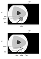
- FIG. 12 is a diagram showing an example of identification display according to the operating state of the instrument.
- the forceps 900A is inserted in the observation image 812, but the blade is closed (non-operated state), so that the instrument information recognition unit 224 is “prepared for biopsy”. Can be judged. Therefore, the display control unit 226 fills in and displays the region of interest 836 (the region of interest recognized by the region of interest 222; the true region of interest is the region of interest 832) to enhance the discriminating power.
- the region of interest 836 the region of interest recognized by the region of interest 222; the true region of interest is the region of interest 832
- the instrument information recognition unit 224 determines that it is in the “biopsy state”. As a result, the display control unit 226 displays the contour of the region of interest 838 to reduce the discriminating power.
- FIG. 13 is a diagram showing another example of the identification display according to the operating state of the instrument.
- the snare 902 instrument, treatment instrument
- the wire ring 902A is not caught in the region of interest 840 (lesion), so that the instrument information
- the recognition unit 224 can determine that it is "ready for biopsy". Therefore, the display control unit 226 superimposes and displays the figure 866A (figure) on the region of interest 840 to enhance the discriminating power.
- the display control unit 226 superimposes and displays the figure 866A (figure) on the region of interest 840 to enhance the discriminating power.
- the instrument information recognition unit 224 can determine that it is in the “biopsy state”. .. Therefore, the display control unit 226 superimposes and displays a small circular figure 866B (graphic figure) on the region of interest 840, and the discriminating power is lower than the state shown in the portion (a) of the figure.
- the instrument information recognition unit 224 may determine that "the instrument overlaps the observation area (distance is equal to or less than the threshold value)".
- FIG. 14 is a diagram showing still another example of the identification display according to the operating state of the instrument.
- the snare 902 instrument, treatment tool
- the wire ring 902A is caught in the region of interest 840 (lesion), but the ring 902A is open.
- the instrument information recognition unit 224 can determine that the device is "ready for biopsy". Therefore, the display control unit 226 superimposes and displays the figure 868A (figure) on the region of interest 840 to enhance the discriminating power.
- the display control unit 226 superimposes and displays the figure 868A (figure) on the region of interest 840 to enhance the discriminating power.
- the instrument information recognition unit 224 can determine that it is in the “biopsy state”. Therefore, the display control unit 226 superimposes and displays the arrow 869A (symbol) and the point 869B (figure, symbol) on the region of interest 840, and the discriminating power is lower than the state shown in the portion (a) of the figure.
- FIG. 15 is a diagram showing still another example of the identification display according to the operating state of the instrument.
- the instrument information recognition unit 224 can determine that it is "ready for biopsy” and display it.
- the control unit 226 superimposes and displays the figure 870A (figure) on the region of interest 842 to enhance the discriminating power.
- the instrument information recognition unit 224 can determine that it is in the “biopsy state”.
- the display control unit 226 superimposes and displays the arrow 870B (symbol) and the point 870C (figure, symbol) on the region of interest 840, and the discriminating power is lower than the state shown in the portion (a) of the figure.
- the user can define the biopsy state and the like as necessary.
- the mode of identification display can be set, the instrument information recognition unit 224 recognizes the instrument information, and the display control unit 226 identifies and displays the observation image based on the recognition result, so that the region of interest is displayed with appropriate discriminating power. can do.
- Fluorescence is a medical image processing device obtained by irradiating a living body with excitation light having a peak of 390 or more and 470 nm or less.
Landscapes
- Engineering & Computer Science (AREA)
- Health & Medical Sciences (AREA)
- Life Sciences & Earth Sciences (AREA)
- Surgery (AREA)
- Physics & Mathematics (AREA)
- General Health & Medical Sciences (AREA)
- Medical Informatics (AREA)
- Public Health (AREA)
- Nuclear Medicine, Radiotherapy & Molecular Imaging (AREA)
- Biomedical Technology (AREA)
- Molecular Biology (AREA)
- Radiology & Medical Imaging (AREA)
- Heart & Thoracic Surgery (AREA)
- Animal Behavior & Ethology (AREA)
- Veterinary Medicine (AREA)
- Theoretical Computer Science (AREA)
- General Physics & Mathematics (AREA)
- Pathology (AREA)
- Optics & Photonics (AREA)
- Biophysics (AREA)
- Multimedia (AREA)
- Computer Vision & Pattern Recognition (AREA)
- Evolutionary Computation (AREA)
- Artificial Intelligence (AREA)
- Software Systems (AREA)
- Epidemiology (AREA)
- Primary Health Care (AREA)
- Robotics (AREA)
- Signal Processing (AREA)
- Computing Systems (AREA)
- Databases & Information Systems (AREA)
- Biodiversity & Conservation Biology (AREA)
- Endoscopes (AREA)
Priority Applications (4)
| Application Number | Priority Date | Filing Date | Title |
|---|---|---|---|
| JP2022545530A JP7594015B2 (ja) | 2020-08-24 | 2021-07-16 | 医療画像処理装置、医療画像処理装置の作動方法、内視鏡システム、及び医療画像処理プログラム |
| EP21861035.0A EP4201301A4 (en) | 2020-08-24 | 2021-07-16 | MEDICAL IMAGE PROCESSING DEVICE, MEDICAL IMAGE PROCESSING METHOD, ENDOSCOPE SYSTEM AND MEDICAL IMAGE PROCESSING PROGRAM |
| CN202180057349.7A CN116234487B (zh) | 2020-08-24 | 2021-07-16 | 医疗图像处理装置、医疗图像处理方法、内窥镜系统及记录介质 |
| US18/158,336 US12478437B2 (en) | 2020-08-24 | 2023-01-23 | Medical image processing apparatus, medical image processing method, endoscope system, and medical image processing program |
Applications Claiming Priority (2)
| Application Number | Priority Date | Filing Date | Title |
|---|---|---|---|
| JP2020140943 | 2020-08-24 | ||
| JP2020-140943 | 2020-08-24 |
Related Child Applications (1)
| Application Number | Title | Priority Date | Filing Date |
|---|---|---|---|
| US18/158,336 Continuation US12478437B2 (en) | 2020-08-24 | 2023-01-23 | Medical image processing apparatus, medical image processing method, endoscope system, and medical image processing program |
Publications (1)
| Publication Number | Publication Date |
|---|---|
| WO2022044606A1 true WO2022044606A1 (ja) | 2022-03-03 |
Family
ID=80355025
Family Applications (1)
| Application Number | Title | Priority Date | Filing Date |
|---|---|---|---|
| PCT/JP2021/026720 Ceased WO2022044606A1 (ja) | 2020-08-24 | 2021-07-16 | 医療画像処理装置、医療画像処理方法、内視鏡システム、及び医療画像処理プログラム |
Country Status (5)
| Country | Link |
|---|---|
| US (1) | US12478437B2 (https=) |
| EP (1) | EP4201301A4 (https=) |
| JP (1) | JP7594015B2 (https=) |
| CN (1) | CN116234487B (https=) |
| WO (1) | WO2022044606A1 (https=) |
Cited By (1)
| Publication number | Priority date | Publication date | Assignee | Title |
|---|---|---|---|---|
| CN115265620A (zh) * | 2022-09-28 | 2022-11-01 | 明度智云(浙江)科技有限公司 | 一种仪器显示数据的获取录入方法、装置和存储介质 |
Citations (3)
| Publication number | Priority date | Publication date | Assignee | Title |
|---|---|---|---|---|
| JP2016064281A (ja) * | 2015-12-25 | 2016-04-28 | オリンパス株式会社 | 内視鏡装置 |
| WO2020036224A1 (ja) | 2018-08-17 | 2020-02-20 | 富士フイルム株式会社 | 内視鏡システム |
| US20200188033A1 (en) * | 2018-12-13 | 2020-06-18 | Covidien Lp | Thoracic imaging, distance measuring, surgical awareness, and notification system and method |
Family Cites Families (11)
| Publication number | Priority date | Publication date | Assignee | Title |
|---|---|---|---|---|
| JPH09149876A (ja) * | 1995-11-30 | 1997-06-10 | Olympus Optical Co Ltd | 内視鏡装置 |
| JP4063933B2 (ja) * | 1997-12-01 | 2008-03-19 | オリンパス株式会社 | 手術シミュレーション装置 |
| US11452464B2 (en) * | 2012-04-19 | 2022-09-27 | Koninklijke Philips N.V. | Guidance tools to manually steer endoscope using pre-operative and intra-operative 3D images |
| WO2017073338A1 (ja) * | 2015-10-26 | 2017-05-04 | オリンパス株式会社 | 内視鏡画像処理装置 |
| US10485629B2 (en) * | 2017-02-24 | 2019-11-26 | Sony Olympus Medical Solutions Inc. | Endoscope device |
| CN110461209B (zh) * | 2017-03-30 | 2021-10-29 | 富士胶片株式会社 | 内窥镜系统及处理器装置 |
| JP6840846B2 (ja) | 2017-06-02 | 2021-03-10 | 富士フイルム株式会社 | 医療画像処理装置、内視鏡システム、診断支援装置、並びに医療業務支援装置 |
| US10835344B2 (en) * | 2017-10-17 | 2020-11-17 | Verily Life Sciences Llc | Display of preoperative and intraoperative images |
| CN109215079B (zh) * | 2018-07-17 | 2021-01-15 | 艾瑞迈迪医疗科技(北京)有限公司 | 图像处理方法、手术导航设备、电子设备、存储介质 |
| JP7206770B2 (ja) * | 2018-10-05 | 2023-01-18 | コニカミノルタ株式会社 | 超音波診断装置、超音波画像表示方法、及びプログラム |
| US11026561B2 (en) * | 2019-03-21 | 2021-06-08 | Verb Surgical Inc. | Method and system for automatically repositioning a viewable area within an endoscope video view |
-
2021
- 2021-07-16 CN CN202180057349.7A patent/CN116234487B/zh active Active
- 2021-07-16 JP JP2022545530A patent/JP7594015B2/ja active Active
- 2021-07-16 WO PCT/JP2021/026720 patent/WO2022044606A1/ja not_active Ceased
- 2021-07-16 EP EP21861035.0A patent/EP4201301A4/en active Pending
-
2023
- 2023-01-23 US US18/158,336 patent/US12478437B2/en active Active
Patent Citations (3)
| Publication number | Priority date | Publication date | Assignee | Title |
|---|---|---|---|---|
| JP2016064281A (ja) * | 2015-12-25 | 2016-04-28 | オリンパス株式会社 | 内視鏡装置 |
| WO2020036224A1 (ja) | 2018-08-17 | 2020-02-20 | 富士フイルム株式会社 | 内視鏡システム |
| US20200188033A1 (en) * | 2018-12-13 | 2020-06-18 | Covidien Lp | Thoracic imaging, distance measuring, surgical awareness, and notification system and method |
Non-Patent Citations (1)
| Title |
|---|
| See also references of EP4201301A4 |
Cited By (2)
| Publication number | Priority date | Publication date | Assignee | Title |
|---|---|---|---|---|
| CN115265620A (zh) * | 2022-09-28 | 2022-11-01 | 明度智云(浙江)科技有限公司 | 一种仪器显示数据的获取录入方法、装置和存储介质 |
| CN115265620B (zh) * | 2022-09-28 | 2023-01-17 | 明度智云(浙江)科技有限公司 | 一种仪器显示数据的获取录入方法、装置和存储介质 |
Also Published As
| Publication number | Publication date |
|---|---|
| CN116234487A (zh) | 2023-06-06 |
| EP4201301A1 (en) | 2023-06-28 |
| US20230157768A1 (en) | 2023-05-25 |
| JP7594015B2 (ja) | 2024-12-03 |
| JPWO2022044606A1 (https=) | 2022-03-03 |
| CN116234487B (zh) | 2026-04-07 |
| US12478437B2 (en) | 2025-11-25 |
| EP4201301A4 (en) | 2024-02-21 |
Similar Documents
| Publication | Publication Date | Title |
|---|---|---|
| JP7430287B2 (ja) | 医用画像処理装置及び内視鏡システム | |
| JP7038641B2 (ja) | 医療診断支援装置、内視鏡システム、及び作動方法 | |
| JP7629050B2 (ja) | 内視鏡システム及び内視鏡システムの作動方法 | |
| JP7170032B2 (ja) | 画像処理装置、内視鏡システム、及び画像処理方法 | |
| JP7278202B2 (ja) | 画像学習装置、画像学習方法、ニューラルネットワーク、及び画像分類装置 | |
| JP7048732B2 (ja) | 画像処理装置、内視鏡システム、及び画像処理方法 | |
| JP7062068B2 (ja) | 画像処理方法及び画像処理装置 | |
| JP2022000163A (ja) | 画像処理装置、内視鏡システム、及び画像処理方法 | |
| JP7290729B2 (ja) | 画像診断支援装置、内視鏡システム、画像診断支援装置の作動方法、及び画像診断支援プログラム | |
| JP2023026480A (ja) | 医療画像処理装置、内視鏡システム、及び医療画像処理装置の作動方法 | |
| JP7600250B2 (ja) | 画像処理システム、プロセッサ装置、内視鏡システム、画像処理方法及びプログラム | |
| JP7530434B2 (ja) | 医療画像処理方法及び医療画像処理装置 | |
| WO2021157487A1 (ja) | 医用画像処理装置、内視鏡システム、医用画像処理方法、及びプログラム | |
| JP7774610B2 (ja) | 医療画像処理装置、内視鏡システム、医療画像処理方法、医療画像処理プログラム、及び記録媒体 | |
| WO2022044606A1 (ja) | 医療画像処理装置、医療画像処理方法、内視鏡システム、及び医療画像処理プログラム | |
| JPWO2020059445A1 (ja) | 画像処理装置及び画像処理方法 | |
| WO2021029293A1 (ja) | 医用画像処理装置、内視鏡システム、及び医用画像処理方法 | |
| WO2021153471A1 (ja) | 医療画像処理装置、医療画像処理方法、及びプログラム |
Legal Events
| Date | Code | Title | Description |
|---|---|---|---|
| 121 | Ep: the epo has been informed by wipo that ep was designated in this application |
Ref document number: 21861035 Country of ref document: EP Kind code of ref document: A1 |
|
| ENP | Entry into the national phase |
Ref document number: 2022545530 Country of ref document: JP Kind code of ref document: A |
|
| NENP | Non-entry into the national phase |
Ref country code: DE |
|
| ENP | Entry into the national phase |
Ref document number: 2021861035 Country of ref document: EP Effective date: 20230324 |