WO2022044592A1 - 樹脂組成物およびこれを含むコーティング組成物、積層用電極、積層用セパレータ、ならびに非水電解質二次電池およびその製造方法 - Google Patents
樹脂組成物およびこれを含むコーティング組成物、積層用電極、積層用セパレータ、ならびに非水電解質二次電池およびその製造方法 Download PDFInfo
- Publication number
- WO2022044592A1 WO2022044592A1 PCT/JP2021/026409 JP2021026409W WO2022044592A1 WO 2022044592 A1 WO2022044592 A1 WO 2022044592A1 JP 2021026409 W JP2021026409 W JP 2021026409W WO 2022044592 A1 WO2022044592 A1 WO 2022044592A1
- Authority
- WO
- WIPO (PCT)
- Prior art keywords
- resin composition
- separator
- vinylidene fluoride
- resin
- structural unit
- Prior art date
- Legal status (The legal status is an assumption and is not a legal conclusion. Google has not performed a legal analysis and makes no representation as to the accuracy of the status listed.)
- Ceased
Links
Classifications
-
- C—CHEMISTRY; METALLURGY
- C08—ORGANIC MACROMOLECULAR COMPOUNDS; THEIR PREPARATION OR CHEMICAL WORKING-UP; COMPOSITIONS BASED THEREON
- C08F—MACROMOLECULAR COMPOUNDS OBTAINED BY REACTIONS ONLY INVOLVING CARBON-TO-CARBON UNSATURATED BONDS
- C08F14/00—Homopolymers and copolymers of compounds having one or more unsaturated aliphatic radicals, each having only one carbon-to-carbon double bond, and at least one being terminated by a halogen
- C08F14/18—Monomers containing fluorine
- C08F14/22—Vinylidene fluoride
-
- C—CHEMISTRY; METALLURGY
- C08—ORGANIC MACROMOLECULAR COMPOUNDS; THEIR PREPARATION OR CHEMICAL WORKING-UP; COMPOSITIONS BASED THEREON
- C08K—Use of inorganic or non-macromolecular organic substances as compounding ingredients
- C08K3/00—Use of inorganic substances as compounding ingredients
- C08K3/01—Use of inorganic substances as compounding ingredients characterized by their specific function
- C08K3/013—Fillers, pigments or reinforcing additives
-
- C—CHEMISTRY; METALLURGY
- C08—ORGANIC MACROMOLECULAR COMPOUNDS; THEIR PREPARATION OR CHEMICAL WORKING-UP; COMPOSITIONS BASED THEREON
- C08L—COMPOSITIONS OF MACROMOLECULAR COMPOUNDS
- C08L27/00—Compositions of homopolymers or copolymers of compounds having one or more unsaturated aliphatic radicals, each having only one carbon-to-carbon double bond, and at least one being terminated by a halogen; Compositions of derivatives of such polymers
- C08L27/02—Compositions of homopolymers or copolymers of compounds having one or more unsaturated aliphatic radicals, each having only one carbon-to-carbon double bond, and at least one being terminated by a halogen; Compositions of derivatives of such polymers not modified by chemical after-treatment
- C08L27/12—Compositions of homopolymers or copolymers of compounds having one or more unsaturated aliphatic radicals, each having only one carbon-to-carbon double bond, and at least one being terminated by a halogen; Compositions of derivatives of such polymers not modified by chemical after-treatment containing fluorine atoms
- C08L27/16—Homopolymers or copolymers or vinylidene fluoride
-
- C—CHEMISTRY; METALLURGY
- C09—DYES; PAINTS; POLISHES; NATURAL RESINS; ADHESIVES; COMPOSITIONS NOT OTHERWISE PROVIDED FOR; APPLICATIONS OF MATERIALS NOT OTHERWISE PROVIDED FOR
- C09D—COATING COMPOSITIONS, e.g. PAINTS, VARNISHES OR LACQUERS; FILLING PASTES; CHEMICAL PAINT OR INK REMOVERS; INKS; CORRECTING FLUIDS; WOODSTAINS; PASTES OR SOLIDS FOR COLOURING OR PRINTING; USE OF MATERIALS THEREFOR
- C09D127/00—Coating compositions based on homopolymers or copolymers of compounds having one or more unsaturated aliphatic radicals, each having only one carbon-to-carbon double bond, and at least one being terminated by a halogen; Coating compositions based on derivatives of such polymers
- C09D127/02—Coating compositions based on homopolymers or copolymers of compounds having one or more unsaturated aliphatic radicals, each having only one carbon-to-carbon double bond, and at least one being terminated by a halogen; Coating compositions based on derivatives of such polymers not modified by chemical after-treatment
- C09D127/12—Coating compositions based on homopolymers or copolymers of compounds having one or more unsaturated aliphatic radicals, each having only one carbon-to-carbon double bond, and at least one being terminated by a halogen; Coating compositions based on derivatives of such polymers not modified by chemical after-treatment containing fluorine atoms
- C09D127/16—Homopolymers or copolymers of vinylidene fluoride
-
- H—ELECTRICITY
- H01—ELECTRIC ELEMENTS
- H01M—PROCESSES OR MEANS, e.g. BATTERIES, FOR THE DIRECT CONVERSION OF CHEMICAL ENERGY INTO ELECTRICAL ENERGY
- H01M4/00—Electrodes
- H01M4/02—Electrodes composed of, or comprising, active material
- H01M4/13—Electrodes for accumulators with non-aqueous electrolyte, e.g. for lithium-accumulators; Processes of manufacture thereof
-
- H—ELECTRICITY
- H01—ELECTRIC ELEMENTS
- H01M—PROCESSES OR MEANS, e.g. BATTERIES, FOR THE DIRECT CONVERSION OF CHEMICAL ENERGY INTO ELECTRICAL ENERGY
- H01M50/00—Constructional details or processes of manufacture of the non-active parts of electrochemical cells other than fuel cells, e.g. hybrid cells
- H01M50/40—Separators; Membranes; Diaphragms; Spacing elements inside cells
- H01M50/409—Separators, membranes or diaphragms characterised by the material
- H01M50/411—Organic material
- H01M50/414—Synthetic resins, e.g. thermoplastics or thermosetting resins
- H01M50/426—Fluorocarbon polymers
-
- Y—GENERAL TAGGING OF NEW TECHNOLOGICAL DEVELOPMENTS; GENERAL TAGGING OF CROSS-SECTIONAL TECHNOLOGIES SPANNING OVER SEVERAL SECTIONS OF THE IPC; TECHNICAL SUBJECTS COVERED BY FORMER USPC CROSS-REFERENCE ART COLLECTIONS [XRACs] AND DIGESTS
- Y02—TECHNOLOGIES OR APPLICATIONS FOR MITIGATION OR ADAPTATION AGAINST CLIMATE CHANGE
- Y02E—REDUCTION OF GREENHOUSE GAS [GHG] EMISSIONS, RELATED TO ENERGY GENERATION, TRANSMISSION OR DISTRIBUTION
- Y02E60/00—Enabling technologies; Technologies with a potential or indirect contribution to GHG emissions mitigation
- Y02E60/10—Energy storage using batteries
Definitions
- the present invention relates to a resin composition and a coating composition containing the same, a laminating electrode, a laminating separator, a non-aqueous electrolyte secondary battery, and a method for producing the same.
- non-aqueous electrolyte secondary batteries (hereinafter, also simply referred to as “secondary batteries”) have been used for various purposes, and their capacities are required to be increased.
- second batteries many wound-type secondary batteries in which electrodes (in the present specification, positive electrodes and negative electrodes are collectively referred to as “electrodes”) and separators are wound have been developed.
- electrodes in the present specification, positive electrodes and negative electrodes are collectively referred to as “electrodes”
- separators are wound-type secondary batteries in which electrodes (in the present specification, positive electrodes and negative electrodes are collectively referred to as “electrodes”) and separators are wound have been developed.
- rice field In order to increase the capacity and energy density of a secondary battery, attention is being paid to a laminated secondary battery in which electrodes and separators are laminated and a secondary battery having a light and soft pouch film on the exterior. Further, since such a secondary battery is used for various purposes, safety is further emphasized.
- the electrodes and the separator are more likely to shift as compared with the wound type secondary battery.
- the electrodes and separators are likely to be displaced from a desired position or wrinkled.
- the wound electrode / separator laminate may loosen after a lapse of time after the winding, and may be displaced during transportation or insertion into the exterior body.
- the positions of the electrodes and separators are displaced when an external force is applied when the secondary battery is used or when the electrodes expand and contract due to charging and discharging. If such misalignment or wrinkles occur in a secondary battery, it becomes difficult to obtain desired performance and sufficient safety.
- a resin-containing layer between the separator and the electrode to fix the positions of the separator and the electrode.
- a resin-containing layer containing two types of polyvinylidene fluoride-based polymers is placed between the separator and the electrode, and the separator and the electrode are bonded by hot pressing before impregnating with the electrolytic solution (hereinafter, “dry bonding”).
- dry bonding a resin-containing layer containing two types of polyvinylidene fluoride-based polymers
- the dry adhesiveness of the resin-containing layer when the dry adhesiveness of the resin-containing layer is high, the wet adhesiveness is low, and when the wet adhesiveness is high, the dry adhesiveness is low.
- the resin vinylidene fluoride-based polymer in Patent Documents 1 and 2
- the resin-containing layer softens during dry adhesion, and the resin-containing layer is embedded in the electrode layer, thereby forming the separator and the separator. Glue the electrodes.
- the resin swollen by the electrolytic solution melts during hot pressing, infiltrates into the electrode layer, cools, and then gels to form a separator and. Glue the electrodes. That is, in dry bonding and wet bonding, the bonding mechanism is different, and it is very difficult to achieve both physical properties that contribute to each bonding. Further, in particular, in the composition containing the polyvinylidene fluoride-based polymer described in Patent Document 1 and Patent Document 2, it is difficult to sufficiently obtain wet adhesiveness.
- the desired adhesive strength can be developed only in a very narrow temperature range at the time of wet adhesion, and it is difficult to control the heating temperature. Therefore, it is also required to provide a resin composition that can be wet-bonded in a wider temperature range.
- the present invention has been made in view of the above problems. It is an object of the present invention to provide a resin composition which is excellent in both dry adhesiveness and wet adhesiveness and which can be wet-adhered in a wider temperature range than the conventional one.
- the present invention provides the following resin compositions (coating agents).
- the present invention also provides the following coating composition (coating liquid).
- a coating composition containing the above resin composition and a solvent.
- the present invention also provides the following stacking electrodes.
- a laminating electrode having an electrode and a resin-containing layer containing the resin composition arranged on at least one surface of the electrode.
- the present invention also provides the following laminating separators.
- a separator for lamination comprising a separator and a resin-containing layer containing the resin composition arranged on at least one surface of the separator.
- the present invention also provides the following non-aqueous electrolyte secondary batteries.
- a non-aqueous electrolyte comprising a positive electrode, a separator, a negative electrode, and further having a resin-containing layer containing the resin composition between the positive electrode and the separator and / or between the negative electrode and the separator. Secondary battery.
- the present invention also provides the following method for manufacturing a non-aqueous electrolyte secondary battery.
- a method for manufacturing a non-aqueous electrolyte secondary battery which comprises a step of heat-pressing a body.
- the resin composition of the present invention is excellent in both dry adhesiveness and wet adhesiveness, and further, when wet-bonding, it is possible to bond separators, electrodes, etc. in a wider processing temperature range than before.
- the resin composition (coating agent) of the present invention is a resin composition mainly used for forming a resin-containing layer for fixing an electrode of a non-aqueous electrolyte secondary battery and a separator.
- the use of the resin composition (coating agent) is not limited to the resin-containing layer.
- the terms "resin composition” and “coating agent” are used interchangeably.
- the temperature at which wet adhesion is possible that is, the processing temperature range in which sufficient adhesive strength is exhibited after wet adhesion (hereinafter, also referred to as "process window") is narrow, and it is also required to widen the process window. Was being done.
- At least one of the plurality of vinylidene fluoride polymers in the resin composition containing two or more kinds of vinylidene fluoride polymers is carboxy.
- Each of the plurality of vinylidene fluoride polymers contains a structural unit containing a group in an amount of 95 mol% or more based on the total amount of the structural unit derived from vinylidene fluoride, and the resin composition has the following two physical properties. It was clarified that when the conditions were met, both wet adhesiveness and dry adhesiveness were enhanced, and the process window for wet adhesion was wider than before.
- the above effect is obtained when the total heat of melting in the second temperature rise of the differential scanning calorimetry is 20 J / g or more and 50 J / g or less and the intrinsic viscosity is 2.5 dL / g or less.
- the total heat of fusion in the second temperature rise of the differential scanning calorimetry is the amount of heat of melting of a film cast from a solution in which the resin composition is dissolved in N-methyl-2-pyrrolidone. Refers to the amount of heat required for the entire resin composition to melt when measured in accordance with.
- the straight line connecting the points before the endotherm is detected and the points after all the endothermic is detected in the melting curve obtained by the second temperature raising process is used as the baseline. Then, the amount of heat of melting obtained based on the baseline is taken as the total amount of heat of melting in the second temperature rise.
- the total heat of melting may be 20 J / g or more and 50 J / g or less, but more preferably 30 J / g or more and 50 J / g or less, and more preferably 35 J / g or more and 45 J / g or less.
- the total heat of melting is 20 J / g or more, the crystallinity of the resin composition becomes moderately high, and the adhesive strength with the electrode, the separator, or the like tends to be good after the resin composition is melted. That is, when the total heat of melting is 20 J / g or more, the wet adhesiveness tends to be good.
- the total heat of melting is 50 J / g or less, the crystallinity of the resin composition does not become excessively high, and the resin composition softens at an appropriate temperature, so that the dry adhesiveness tends to be good.
- the total amount of heat of melting can be adjusted by the amount of the structural unit derived from vinylidene fluoride contained in each vinylidene fluoride polymer. For example, as the proportion of constituent units derived from vinylidene fluoride increases, the total amount of heat of melting tends to increase.
- the intrinsic viscosity is the viscosity ⁇ of the resin composition-containing solution (a solution in which 80 mg of the resin composition is dissolved in 20 ml of N, N-dimethylformamide) measured using a Ubbelohde viscous meter in a constant temperature bath at 30 ° C. It is a value obtained from 1 and the viscosity ⁇ 0 of N, N-dimethylformamide measured using an Ubbelohde viscous meter in a constant temperature bath at 30 ° C.
- the intrinsic viscosity may be 2.5 dL / g or less, but more preferably 0.8 dL / g or more and 2.5 dL / g or less, and more preferably 1.5 dL / g or more and 2.4 dL / g or less.
- the intrinsic viscosity can be adjusted, for example, by the molecular weight of each vinylidene fluoride polymer in the resin composition. When the resin composition contains a large amount of vinylidene fluoride polymer having a large molecular weight, the intrinsic viscosity tends to increase.
- the resin composition has a ratio A 1740 / A 3020 of the absorbance A 1740 of the infrared absorption spectrum at a wave number of 1740 cm -1 to the absorbance A 3020 of the infrared absorption spectrum at 3020 cm -1 of 0.15 or more. Is more preferable.
- the absorption at 1740 cm -1 of the infrared absorption spectrum is the absorption by the group represented by -CO-O- in the vinylidene fluoride polymer, and the absorption at 3020 cm -1 is the absorption in the vinylidene fluoride polymer. Absorption by the group represented by -CH 2- .
- the absorbance at 1740 cm -1 in the vinylidene fluoride polymer represents the amount of carboxy groups and ester groups contained in the vinylidene fluoride polymer
- the absorbance at 3020 cm -1 is the total amount of the constituent units in the vinylidene fluoride polymer. Represents. Therefore, these ratios A 1740 / A 3020 are also referred to as "carboxy group, etc.” in the resin composition (vinylidene fluoride polymer) as a carboxy group and an ester group (hereinafter, when it is not particularly necessary to distinguish between them). Represents how much) is included.
- the absorbance detected at 1600 cm -1 or more and 1800 cm -1 or less is the absorbance A 1740 at 1740 cm -1
- the absorbance detected at 2900 cm -1 or more and 3100 cm -1 or less is the absorbance A at 3020 cm -1 . Treat as 3020 .
- the above-mentioned absorbance is usually obtained directly from the resin composition, but if the types of a plurality of vinylidene fluoride polymers contained in the resin composition and their content ratios are known, vinyllidene fluoride is used.
- the absorbance ratio (A 1740 / A 3020 ) may be calculated for each polymer, and the absorbance ratio (weighted average value) of the entire resin composition may be obtained based on the content ratio of the vinylidene fluoride polymer.
- the ratio A 1740 / A 3020 may be 0.15 or more, more preferably 0.2 or more, still more preferably 0.23 or more.
- the upper limit is usually preferably 0.8 or less, more preferably 0.5 or less.
- the ratio is 0.15 or more, the adhesiveness of the resin composition to the separator, the electrode, or the like is improved, and the strength of the resin-containing layer itself can be improved.
- a force is also applied to the separator and the interface between the electrode and the resin-containing layer by a heat press.
- the adhesiveness between the separator or the electrode and the resin-containing layer is weak, the interface is easily peeled off, and the electrode and the separator cannot be sufficiently adhered.
- the amount of the carboxy group or the like is equal to or more than the above value, the strength of the resin-containing layer (resin composition) described later with respect to the separator and the electrode becomes sufficiently high, and the resin composition is softened and deformed by a heating press. Even so, the shape of the resin-containing layer can be easily maintained.
- the resin-containing layer contains not only the resin composition but also the filler
- the carboxy groups and the like in the resin composition and the OH groups on the surface of the filler are likely to interact with each other, and the shape of the resin-containing layer is more likely to be maintained.
- the degree to which the polymer melts and diffuses during wet bonding can be adjusted appropriately, and the process window becomes wider. It is considered that the polarities of the carboxy group and the ester group contribute to the above effect, and the polarity of the carboxy group particularly contributes.
- the resin composition of the present invention may contain two or more of the following vinylidene fluoride polymers, and the number of vinylidene fluoride polymers is not particularly limited.
- the number of vinylidene fluoride polymers is not particularly limited.
- three or more kinds of vinylidene fluoride polymers may be contained, but two kinds are preferable from the viewpoint that all the above-mentioned physical properties can be easily contained in a desired range.
- At least one of the plurality of vinylidene fluoride polymers may contain a structural unit containing a carboxy group, and all vinylidene fluoride polymers contain a structural unit containing a carboxy group. May be good.
- the vinylidene fluoride polymer containing a carboxy group and the vinylidene fluoride polymer not containing a carboxy group will be described.
- the resin composition may contain both of these, or may contain only the vinylidene fluoride polymer containing a carboxy group.
- the amount of vinylidene fluoride-derived structural units in the vinylidene fluoride polymer containing a carboxy group is 95 mol% or more based on the total amount of the structural units of the vinylidene fluoride polymer. However, 95 mol% or more and 99.5 mol% or less are more preferable, and 95.2 mol% or more and 99 mol% or less are further preferable.
- the amount of the constituent units derived from vinylidene fluoride is 95 mol% or more with respect to the total amount of the constituent units of the vinylidene fluoride polymer, the total heat of fusion of the above-mentioned resin composition tends to be 20 J / g or more.
- the vinylidene fluoride polymer partially contains a structural unit derived from vinylidene fluoride and a structural unit other than the structural unit containing a carboxy group (such as a structural unit derived from a fluorine-containing monomer described later). Is preferable.
- the amount of the building blocks derived from vinylidene fluoride in the vinylidene fluoride polymer can be specified by analyzing the vinylidene fluoride polymer by 19 F-NMR.
- the amount of the structural unit containing a carboxy group in the vinylidene fluoride polymer that is, the amount of the structural unit derived from the compound containing the carboxy group is the same as the structural unit derived from vinylidene fluoride and the structural unit derived from other compounds. It may be a degree that does not impair the effect of the polymer, and may be a degree that does not impair the effect of the structural unit containing the carboxy group.
- the amount of the structural unit containing the carboxy group is preferably 0.05 mol% or more and 0.5 mol% or less, and 0.05 mol% or more and 0. 4 mol% or less is more preferable, and 0.1 mol% or more and 0.3 mol% or less is further preferable.
- the amount of the structural unit derived from the compound containing a carboxy group in the vinylidene fluoride polymer is the absorbance of the infrared absorption spectrum described above (for example, the absorbance of the infrared absorption spectrum in 1740 cm -1 of the resin composition A 1740 and 3020 cm -1 . It can be analyzed from the ratio A 1740 / A 3020 ) with the absorbance A 3020 of the infrared absorption spectrum in.
- the amount of the structural unit derived from the compound containing the carboxy group is preferably appropriately selected in consideration of the total amount of the carboxy group and the like in the resin composition.
- the ratio A 1740 / A 3020 of the absorbance A 1740 of the infrared absorption spectrum at 1740 cm -1 and the absorbance A 3020 of the infrared absorption spectrum at 3020 cm -1 of the resin composition is 0.15 or more.
- the structure of the structural unit derived from the compound containing the carboxy group is not particularly limited, but the structural unit derived from the unsaturated dibasic acid, the unsaturated dibasic acid monoester, or the compound represented by the general formula (1) described later can be used. Especially preferable.
- the vinylidene fluoride polymer may contain only one kind of structure derived from these, or may contain two or more kinds of structures.
- the unsaturated dibasic acid examples include a compound having an unsaturated double bond and two carboxy groups or an acid anhydride group.
- the unsaturated dibasic acid preferably has 5 to 8 carbon atoms. Specific examples thereof include fumaric acid, (maleic anhydride) maleic acid, citraconic acid, phthalic acid and the like.
- unsaturated dibasic acid monoesters examples include compounds having an unsaturated double bond, one carboxylic acid, and one carboxylic acid ester.
- the unsaturated dibasic acid monoester preferably has 5 to 8 carbon atoms.
- Specific examples of unsaturated dibasic acid esters include monomethyl fumarate, monoethyl fumarate, monomethyl maleate, monoethyl maleate, monomethyl citraconic acid, monoethyl citraconic acid, monomethyl phthalate, monoethyl phthalate and the like.
- R 1 , R 2 , and R 3 independently represent a hydrogen atom, a chlorine atom, or an alkyl group having 1 to 5 carbon atoms.
- R 1 , R 2 , and R 3 are preferably a group having a small steric hindrance, preferably a hydrogen atom or an alkyl group having 1 to 3 carbon atoms, and more preferably a hydrogen atom or a methyl group. ..
- R 1 , R 2 , and R 3 may all be the same or different.
- X' represents an atomic group having a molecular weight of 472 or less and having 1 to 19 atoms in the main chain.
- X'in includes a cyclic structure or the like, there may be a plurality of atoms in the main chain. In this case, the minimum value is treated as the number of atoms in the main chain of X'.
- Specific examples of the compound represented by the general formula (1) include acryloyloxypropyl succinic acid, acryloyloxyethyl succinic acid, methacryloyloxyethyl succinic acid, methacryloxypropyl succinic acid, and 2-carboxyethyl acrylate. , 2-carboxyethyl methacrylate, acryloyloxyethyl phthalic acid, methacryloyloxyethyl phthalic acid, N-carboxyethyl (meth) acrylamide, carboxyethyl thio (meth) acrylate, carboxymethyl acrylate and the like.
- (meth) acryloyloxy refers to methacryloyloxy, acryloyloxy, or both.
- (meth) acrylate represents methacrylate, acrylate, or both
- (meth) acrylic represents methacrylic, acrylic, or both.
- the compound containing the carboxy group is preferably maleic acid monomethyl ester, (meth) acryloyloxypropylsuccinic acid, or (meth) acryloyloxyethyl succinic acid from the viewpoint of reactivity and the like.
- maleic acid monomethyl ester or acryloyloxypropylsuccinic acid is preferable.
- the vinylidene fluoride polymer containing a carboxy group further contains a structural unit (other structural unit) other than the structural unit derived from the compound other than vinylidene fluoride and the compound containing the carboxy group.
- other structural units include structural units derived from fluorine-containing monomers other than vinylidene fluoride; structural units derived from hydrocarbon-based monomers such as ethylene and propylene.
- fluorine-containing monomers examples include vinyl fluoride, trifluoroethylene, tetrafluoroethylene, chlorotrifluoroethylene, hexafluoropropylene, hexafluoroethylene, fluoroalkyl vinyl ether, and perfluoromethyl vinyl ether. Alkyl vinyl ether and the like are included. Among these, a structural unit derived from chlorotrifluoroethylene or hexafluoropropylene is preferable from the viewpoint that the resin composition easily satisfies the above-mentioned physical properties.
- the melting point of the vinylidene fluoride polymer containing the carboxy group is preferably 100 ° C. or higher and 190 ° C. or lower, and more preferably 120 ° C. or higher and 175 ° C. or lower.
- the melting point of the vinylidene fluoride polymer can be specified by measuring the calorific value with a differential scanning calorimeter (DSC). Specifically, the vinylidene fluoride polymer is heated from 30 ° C. to 230 ° C. at 10 ° C./min (first temperature rise) and lowered from 230 ° C. to 30 ° C. at 10 ° C./min (first time). The temperature is further increased from 30 ° C. to 230 ° C. at 10 ° C./min (second temperature increase), and the melting peak is specified by DSC. Then, the maximum melting peak temperature Tm observed at the second temperature rise is specified as the melting point of the vinylidene fluoride polymer.
- the weight average molecular weight of the vinylidene fluoride polymer containing a carboxy group is preferably 50,000 to 3 million, more preferably 100,000 to 2 million, and even more preferably 200,000 to 1.5 million.
- the weight average molecular weight is a polystyrene-equivalent value measured by gel permeation chromatography (GPC).
- GPC gel permeation chromatography
- the above-mentioned vinylidene fluoride polymer containing a carboxy group can be obtained by polymerizing vinylidene fluoride, a compound containing a carboxy group, and, if necessary, other compounds by a known method.
- methods for copolymerizing these include suspension polymerization, emulsion polymerization, solution polymerization and the like.
- the amount of vinylidene fluoride-derived structural units in the vinylidene fluoride polymer without carboxy group is 95 mol% or more with respect to the total amount of structural units of the vinylidene fluoride polymer. However, it is more preferably 95 mol% or more and 99.5 mol% or less, and further preferably 95 mol% or more and 99 mol% or less. When the amount of the constituent unit derived from vinylidene fluoride is 95 mol% or more, the total heat of melting of the above-mentioned resin composition tends to be 20 J / g or more.
- the amount of the building blocks derived from vinylidene fluoride in the vinylidene fluoride polymer can be specified by analyzing the vinylidene fluoride polymer by 19 F-NMR.
- the vinylidene fluoride polymer containing no carboxy group may be a homopolymer of vinylidene fluoride, but may contain a structural unit (other structural unit) derived from a compound other than vinylidene fluoride.
- other structural units include structural units derived from fluorine-containing monomers other than vinylidene fluoride; structural units derived from hydrocarbon-based monomers such as ethylene and propylene.
- the vinylidene fluoride polymer may contain only one kind of these, or may contain two or more kinds of them.
- the structural unit derived from the fluorine-containing monomer is the same as the structural unit derived from the fluorine-containing monomer contained in the above-mentioned vinylidene fluoride polymer containing a carboxy group.
- a structural unit derived from chlorotrifluoroethylene or hexafluoropropylene is preferable from the viewpoint that the resin composition easily satisfies the above-mentioned physical properties.
- the melting point of the vinylidene fluoride polymer containing no carboxy group is preferably 100 ° C. or higher and 190 ° C. or lower, and more preferably 120 ° C. or higher and 175 ° C. or lower.
- the melting point of the vinylidene fluoride polymer can be specified in the same manner as the melting point of the vinylidene fluoride polymer containing the above-mentioned carboxy group.
- the weight average molecular weight of the vinylidene fluoride polymer containing no carboxy group is preferably 50,000 to 3 million, more preferably 100,000 to 2 million, and even more preferably 200 to 1.5 million.
- the weight average molecular weight is a polystyrene-equivalent value measured by gel permeation chromatography (GPC).
- GPC gel permeation chromatography
- the above-mentioned carboxy group-free fluorovinylidene polymer can be obtained by polymerizing vinylidene fluoride and other compounds, if necessary, by a known method.
- methods for copolymerizing these include suspension polymerization, emulsion polymerization, solution polymerization and the like.
- the resin composition of the present invention can be prepared by preparing a plurality of vinylidene fluoride polymers, respectively, and mixing them.
- the powder of each vinylidene fluoride polymer may be mixed by a known method.
- a plurality of vinylidene fluoride polymers may be mixed by melt-kneading or the like and processed into pellets or particles.
- the resin composition may contain components other than the above-mentioned vinylidene fluoride polymer as long as the object and effect of the present invention are not impaired.
- the coating composition (coating liquid) of the present invention is a composition mainly for forming a resin-containing layer for adhering a separator of a non-electrolyte secondary battery and an electrode, and includes the above-mentioned resin composition.
- the coating composition (coating liquid) can be, for example, a composition obtained by dispersing or dissolving the above-mentioned resin composition in a solvent, and may further contain a filler. Further, various additives may be contained as long as the object and effect of the present invention are not impaired.
- the use of the coating composition (coating liquid) is not limited to the formation of the resin-containing layer.
- the terms "coating composition” and “coating liquid” are used interchangeably.
- the amount of the resin composition in the coating composition is appropriately selected according to the coating method of the coating composition, the thickness of the desired resin-containing layer, and the like.
- the coating composition preferably contains the resin composition in an amount of 3% by mass or more and 50% by mass or less, more preferably 5% by mass or more and 40% by mass or less, and 10% by mass or more and 30% by mass or less. It is more preferable to contain% or less.
- the resin composition mainly vinylidene fluoride polymer
- the electrode and the separator can be firmly adhered.
- the type of the solvent contained in the coating composition is not particularly limited as long as the above resin composition can be uniformly dissolved or dispersed.
- solvents include N-methyl-2-pyrrolidone, N, N-dimethylformamide, N, N-dimethylacetamide, dimethyl sulfoxide, hexamethylphosphoamide, dioxane, tetrahydrofuran, tetramethylurea, triethylphosphate, trimethyl.
- Examples include phosphate, acetone, 2-butanone, cyclohexanone and the like.
- the coating composition may contain only one type of solvent, or may contain two or more types of solvent.
- the amount of the solvent is appropriately selected according to the coating method of the coating composition, the desired thickness of the resin-containing layer, and the like.
- the filler is not particularly limited as long as it has insulating properties and is resistant to heat during dry bonding and wet bonding. As described above, when the coating composition and thus the resin-containing layer contain a filler, the shape of the resin-containing layer is easily maintained during wet adhesion. In addition, improvement in the mechanical strength and safety of the battery can be expected.
- fillers examples include SrTIM 3 , SnO 2 , CeO 2 , MgO, NiO, CaO, ZnO, ZrO 2 , Y2O 3, Al2O 3, TiO 2 , SiC , clay minerals, mica, calcium carbonate and the like. included.
- the coating composition may contain only one type of filler, or may contain two or more types of filler.
- Al 2 O 3 and MgO and Zn O are preferable from the viewpoint of the safety of the secondary battery and the liquid coating stability, and Al 2 O 3 is further preferable from the viewpoint of insulating property and electrochemical stability.
- the average particle size of the filler is preferably 5 nm or more and 2 ⁇ m or less, and more preferably 10 nm or more and 1 ⁇ m or less.
- a commercially available product may be used as the filler.
- AKP-3000, AKP-50, AKP-20 (all manufactured by Sumitomo Chemical Co., Ltd.), which are commercially available as high-purity alumina particles, may be used.
- the amount of the filler in the coating composition is appropriately selected according to the coating method of the coating composition, the desired thickness of the resin-containing layer, and the like.
- the coating composition preferably contains a filler in an amount of 30% by mass or more and 99% by mass or less, more preferably 50% by mass or more and 95% by mass or less, and more preferably 70% by mass or more and 90% by mass or less. It is more preferable to include it.
- the filler is contained in the solid content of the coating composition in the above range, the shape of the resin-containing layer is easily maintained during wet adhesion. In addition, improvement in the mechanical strength and safety of the battery can be expected.
- the mixing method of the above resin composition and the filler or the solvent is not particularly limited, and the resin composition can be mixed by a known method.
- the secondary battery of the present invention includes a laminate including a positive electrode, a separator, and a negative electrode, a non-aqueous electrolyte solution, and an exterior body covering them. Further, a resin-containing layer containing the above-mentioned resin composition is arranged between the positive electrode and the separator of the laminated body and / or between the negative electrode and the separator. The resin-containing layer may be arranged only between the positive electrode and the separator and between the negative electrode and the separator, but if the resin-containing layer is arranged in both of them, the electrodes and the separator may be displaced. Wrinkles and the like are less likely to occur, and the strength and performance of the obtained secondary battery are improved. The positive electrode, the separator, and the negative electrode may be wound if necessary.
- the secondary battery may have any structure such as a coin type battery, a button type battery, a cylindrical type battery, a square type battery, and a laminated type battery.
- a coin type battery a coin type battery
- a button type battery a cylindrical type battery
- a square type battery a laminated type battery.
- Electrodes positive and negative electrodes
- the electrode of the secondary battery can be the same as the electrode of a known secondary battery.
- the electrodes typically include a current collector and a mixture layer containing the active material located on at least one surface of the current collector.
- the material of the current collector for the negative electrode and the positive electrode is not particularly limited as long as it can extract electricity.
- Examples of collectors include metal foils such as aluminum, copper, iron, stainless steel, steel, nickel and titanium, metal nets and the like. Further, the surface of another medium may be coated with the above metal foil, metal net, or the like.
- the thickness of the current collector is usually 5 ⁇ m or more and 100 ⁇ m or less.
- the mixture layer is a layer containing an electrode active material and a binder, and if necessary, a conductive auxiliary agent and the like.
- the ratio of the components constituting the mixture layer can be the same as that of the known mixture layer of the secondary battery.
- the thickness of the mixture layer is appropriately adjusted according to the type of the secondary battery, but is usually 20 ⁇ m or more and 250 ⁇ m or less.
- the positive electrode active material contained in the positive electrode mixture layer include the general formula LiMY 2 (M is Co, Ni, Fe, Mn, Cr) such as LiCoO 2 , LiNixCo 1-x O 2 (0 ⁇ x ⁇ 1).
- V represents at least one of the transition metals
- Y represents a chalcogen element such as O, S), a composite metal chalcogen compound; a composite metal oxide having a spinel structure such as LiMn 2 O 4 ; LiFePO 4 etc.
- the olivine type lithium compound and the like are included.
- the positive electrode active material may be a commercially available product.
- examples of the negative electrode active material contained in the negative electrode mixture layer include a carbon material, a metal / alloy material, a metal oxide, and the like, and among these, the carbon material is preferable.
- examples of carbon materials include artificial graphite, natural graphite, non-graphitizable carbon, easily graphitized carbon and the like. When such a carbon material is used, the energy density of the secondary battery tends to be high.
- the artificial graphite can be obtained, for example, by carbonizing an organic material, heat-treating it at a high temperature, and pulverizing and classifying it.
- the non-graphitized carbon can be obtained, for example, by calcining a material derived from petroleum pitch at 1000 ° C. or higher and 1500 ° C. or lower.
- the specific surface area of the positive electrode active material is preferably 0.05 m 2 / g or more and 50 m 2 / g or less.
- the specific surface area of the negative electrode active material is preferably 0.3 m 2 / g or more and 10 m 2 / g or less.
- the specific surface area of the electrode active material can be determined by the nitrogen adsorption method.
- the binder contained in the mixture layer is not particularly limited as long as it can bind the above-mentioned electrode active material and the conductive auxiliary agent described later.
- examples thereof include fluororesins such as polytetrafluoroethylene, polyvinylidene fluoride and fluororubber; mixtures of styrene-butadiene rubber and carboxymethyl cellulose; thermoplastic resins such as polypropylene and polyethylene.
- a vinylidene fluoride polymer can also be used.
- vinylidene fluoride-based polymers include vinylidene fluoride-maleic acid monomethyl ester copolymers and vinylidene fluoride-based polymers obtained by copolymerizing vinylidene fluoride with the above-mentioned compound containing a carboxy group. Etc. are also included.
- the conductive auxiliary agent contained in the electrode mixture layer may be any substance that can improve the conductivity of the electrode mixture layer.
- the conductive auxiliary agent include carbonaceous substances such as carbon black, graphite fine powder and carbon fiber, metal fine powder such as nickel and aluminum, and metal fiber.
- the method for forming the electrode is not particularly limited, and can be formed by, for example, applying a slurry containing an electrode active material, a binder, a conductive auxiliary agent, and a non-aqueous solvent on a current collector and drying (solidifying) the slurry. ..
- non-aqueous solvents include N-methyl-2-pyrrolidone and the like.
- the method of applying the slurry is not particularly limited, and includes a method of applying with a bar coater, a die coater, and a comma coater.
- the drying temperature is usually preferably 50 ° C. or higher and 150 ° C. or lower, and the drying time is 1 minute or longer and 300 minutes or lower.
- the pressure at the time of drying is not particularly limited, and the pressure may be reduced to dry. Further, after drying, further heat treatment may be performed if necessary. Further, the press treatment may be further performed instead of the heat treatment or after the heat treatment. When the press treatment is performed, it is usually preferably 1 MPa (G) or more and 200 MPa (G) or less. Pressing improves the electrode density.
- the separator of the secondary battery is not particularly limited as long as it can electrically insulate the positive electrode and the negative electrode and can hold the electrolytic solution.
- separators include polyolefin polymers such as polyethylene and polypropylene; polyester polymers such as polyethylene terephthalate; aromatic polyamide polymers, polyimide polymers such as polyetherimide; polyethersulfone; polysulfone; polyether. Ketone; polystyrene; polyethylene oxide; polycarbonate; polyvinyl chloride; polyacrylonitrile; polymethylmethacrylate; single-layer or multi-layer porous membrane containing ceramics and the like, non-woven fabric and the like are included. Further, it may be glass, paper or the like.
- a porous membrane of a polyolefin polymer for example, polyethylene, polypropylene, etc.
- a polyolefin polymer for example, polyethylene, polypropylene, etc.
- Examples of commercially available polyolefin-based polymer porous membranes include Cellguard® (single-layer polypropylene separator, single-layer polyethylene separator, polypropylene / polyethylene / polypropylene 3-layer separator, etc.) manufactured by Polypore, and Hypore manufactured by Asahi Kasei Corporation (registered trademark). Includes (registered trademark) (single-layer polyethylene), SETELA (registered trademark) (single-layer polyethylene) manufactured by Toray Co., Ltd., and the like.
- the separator may be surface-treated or may be pre-coated with a layer of inorganic particles.
- the resin-containing layer is a layer obtained by applying a composition containing the above-mentioned resin composition, that is, the above-mentioned coating composition and solidifying the composition.
- the resin-containing layer may be arranged at least one of the positive electrode and the separator and between the negative electrode and the separator, but if they are arranged in both of them, the strength and transportability of the laminated body may be improved. It will increase.
- the thickness of the resin-containing layer is preferably 0.2 ⁇ m or more and 25 ⁇ m or less, and preferably 0.5 ⁇ m or more and 5 ⁇ m or less. The method of forming the resin-containing layer will be described in detail later.
- the non-aqueous electrolyte solution is a solution in which an electrolyte is dissolved in a non-aqueous solvent.
- non-aqueous solvents include aprotic organic solvents capable of transporting cations and anions constituting the electrolyte, which do not substantially impair the function of the secondary battery.
- non-aqueous solvents include organic solvents commonly used as non-aqueous electrolytes for lithium ion secondary batteries, and specific examples include carbonates, halogenated hydrocarbons, ethers, ketones, nitriles, etc. Lactones, esters, oxorane compounds and the like are included. Among them, propylene carbonate, ethylene carbonate, dimethyl carbonate, diethyl carbonate, ethylmethyl carbonate, 1,2-dimethoxyethane, 1,2-diethoxyethane, methyl propionate, ethyl propionate, succinonitrile, 1,3-propane. Sluton, fluoroethylene carbonate, vinylene carbonate and the like are preferable.
- the non-aqueous electrolytic solution may contain only one type of non-aqueous solvent, or may contain two or more types.
- the electrolyte is not particularly limited as long as it can transport cations and anions by the non-aqueous solvent and does not substantially impair the function of the secondary battery.
- Examples of electrolytes when the non-aqueous electrolyte secondary battery is a lithium ion secondary battery include lithium salts of fluoro complex anions such as LiPF 6 , LiAsF 6 , and LBF 4 ; and inorganic lithium such as LiClO 4 , LiCl, and LiBr.
- Lithium sulfonic acid salts such as LiCH 3 SO 3 , LiCF 3 SO 3 , Li (CF 3 OSO 2 ) 2 N, Li (CF 3 OSO 2 ) 3 C, Li (CF 3 SO 2 ) 2 N, Li (CF 3 SO 2 ) Contains organic lithium salts such as 3C .
- the non-aqueous electrolyte solution may contain only one type of electrolyte, or may contain two or more types of electrolytes.
- the shape of the exterior body of the secondary battery is not particularly limited, and is appropriately selected according to the application of the secondary battery and the like.
- the exterior body may be a cylindrical can, a laminated pouch, or the like, as long as it can hold the laminated body including the above-mentioned electrodes, separators, and resin-containing layer and the non-aqueous electrolytic solution.
- the method for manufacturing a secondary battery of the present invention is a step of forming a resin-containing layer containing the above-mentioned resin composition on at least one surface of at least one member selected from the group consisting of a positive electrode, a separator, and a negative electrode.
- Resin-containing layer forming step and a step of laminating the positive electrode, the separator, and the negative electrode so that the resin-containing layer is located between the positive electrode and the separator and between the negative electrode and the separator (lamination).
- a step) and a step of hot-pressing the laminate are included at least.
- the outer body Before the hot pressing step or after the hot pressing step, the outer body may be filled with the laminate and the laminate may be impregnated with the non-aqueous electrolytic solution (non-aqueous electrolytic solution impregnation step). It may include a step of winding later.
- a resin-containing layer containing the above-mentioned resin composition is formed on at least one surface of at least one member selected from the group consisting of a positive electrode, a separator, and a negative electrode. do.
- the method for forming the resin-containing layer may be any method as long as it is a method of applying a coating composition and solidifying it, and any of the following methods can be used.
- a coating composition is applied to one surface of an electrode (positive electrode or negative electrode) and solidified to form a laminated body of an electrode and a resin-containing layer (also referred to as a “laminated electrode” in the present specification).
- the coating composition is applied to one surface or both surfaces of the separator and solidified to form a laminate of the separator and the resin-containing layer (also referred to as "laminator separator” in the present specification).
- the above-mentioned coating composition is applied onto a separately prepared substrate and solidified, then the coating film is peeled off from the substrate, and the coating film is attached to a separator or an electrode.
- the base material include a base material made of polyethylene terephthalate (PET) and the like.
- (1) a method of forming a laminating electrode and (2) a method of forming a laminating separator are preferable in terms of simplification of the base material peeling step and the laminating step. Further, the method (2) for forming the separator for laminating is particularly preferable because the resin-containing layer can be formed without affecting the electrodes.
- the method of applying the above coating composition is not particularly limited.
- the method for solidifying the coating composition can be performed by dipping in a non-solvent, drying, or the like.
- the non-solvent include a solvent that does not dissolve the resin composition such as water.
- a poor solvent such as ethanol may be contained.
- the drying temperature is usually preferably 40 ° C. or higher and 190 ° C. or lower, and more preferably 50 ° C. or higher and 180 ° C. or lower.
- the drying time is preferably 1 second or more and 15 hours or less.
- the atmosphere at the time of drying is not particularly limited, and the product may be dried under nitrogen or under reduced pressure. Further, after drying, further heat treatment may be performed if necessary.
- each member is arranged in the order of the positive electrode, the resin-containing layer, the separator, the resin-containing layer, and the negative electrode.
- the laminating method of the laminating step is appropriately selected depending on which method is used to prepare the resin-containing layer. For example, when a laminating electrode in which a resin-containing layer is laminated on one surface of the electrode is prepared in the resin-containing layer forming step, the laminating electrode is oriented so that the resin-containing layer of the laminating electrode and the separator face each other. And the separator are laminated. When a laminating separator having resin-containing layers formed on both sides of the separator is prepared in the resin-containing layer forming step, the laminating separator is sandwiched between the positive electrode and the negative electrode.
- the laminate formed in the laminating step may include only one unit composed of a positive electrode, a resin-containing layer, a separator, a resin-containing layer, and a negative electrode, or may include a plurality of the units.
- a resin-containing layer or a separator may be further arranged between the units.
- the hot pressing step is a step of hot pressing the laminate produced in the above-mentioned laminating step.
- the hot pressing step may be dry bonding performed before impregnating the laminate with the non-aqueous electrolytic solution, or wet bonding performed after impregnating the laminate with the non-aqueous electrolytic solution.
- only one of dry bonding and wet bonding may be performed, or both may be performed.
- the above-mentioned resin composition exhibits high adhesive strength regardless of whether it is dry-adhesive or wet-adhesive. Therefore, it can be suitably used for both dry bonding and wet bonding.
- Dry Adhesion is performed before the above-mentioned laminate is impregnated with the non-aqueous electrolyte.
- the heating temperature is usually preferably 40 ° C. or higher and 220 ° C. or lower, more preferably 50 ° C. or higher and 120 ° C. or lower.
- the heating time is preferably 1 second or more and 15 hours or less.
- the temperature during wet bonding takes into consideration the heat resistance of the electrodes, separator and electrolyte. Specifically, the upper limit is the lowest temperature among the temperatures at which significant changes (including mere state changes such as chemical structure changes due to decomposition and melting / vaporization) are observed in any of the electrodes, separators, and non-aqueous electrolytes. Select as appropriate.
- the heating temperature is usually preferably room temperature or higher and 130 ° C. or lower, and more preferably 40 ° C. or higher and 100 ° C. or lower.
- the pressure during hot pressing is preferably 0.01 MPa (G) or more and 10 MPa (G), more preferably 0.1 MPa (G) or more and 8 MPa (G) or less.
- the laminate or the non-aqueous electrolytic solution may be preheated before the hot pressing.
- the preheating time is preferably 1 second or more and 1 hour or less.
- the pressing time at the above pressure is more preferably 1 second or more and 1 hour or less.
- a step of filling the above-mentioned exterior body with a dry-bonded laminate or a non-dry-bonded laminate and impregnating the non-aqueous electrolytic solution may be further included. ..
- the method for filling the laminate and the method for impregnating the non-aqueous electrolytic solution are the same as the known method for filling the laminated body of the secondary battery and the method for impregnating the non-aqueous electrolytic solution.
- VDF-HFP-MMM copolymer contained 95.22 mol% of VDF, 4.52 mol% of HFP, and 0.26 mol% of MMM with respect to the total amount of constituent units.
- the ratio A 1740 / A 3020 of the absorbance A 1740 at 1740 cm -1 and the absorbance at 3020 cm- 1 of the vinylidene fluoride polymer was 0.36.
- the intrinsic viscosity ( ⁇ ) of the vinylidene fluoride polymer was 1.4 dL / g. This vinylidene fluoride polymer was designated as polymer 1.
- the VDF / HFP ratio was calculated by 19 F-NMR, the VDF / MMM ratio was calculated by the method described later, and then the total of VDF, HFP and MMM was 100 mol%. It was obtained by calculating so as to be.
- the absorbance ratio was measured by the method described later. Intrinsic viscosity was also measured by the method described below.
- VDF / MMM ratio (molar ratio of the amount of structural units derived from vinylidene fluoride to the amount of structural units derived from monomethyl maleate) in the polymer is the IR spectrum disclosed in International Publication No. 2009/084483. It was calculated based on the calculation method using the calibration curve.
- VDF-HFP-MMM was polymerized in the same manner as in Polymer 1 except that the amount of VDF was changed to obtain Polymer 2.
- the polymer 2 contained 98.86 mol% of VDF, 0.99 mol% of HFP, and 0.15 mol% of MMM with respect to all the constituent units.
- the absorbance ratio A 1740 / A 3020 was 0.18, and the intrinsic viscosity ( ⁇ ) was 3.1 dL / g.
- the amount of each monomer in the polymer 4 was calculated by the same method as in Example 1 for the VDF / CTFE ratio, and after the VDF / APS ratio was calculated by 1 1 H-NMR, the total of VDF, CTFE and APS. was calculated to be 100 mol%.
- the absorbance ratio A 1740 / A 3020 was 0.46, and the intrinsic viscosity ( ⁇ ) was 2.5 dL / g.
- VDF-HFP was polymerized in the same manner as in Polymer 1 except that MMM was not used to obtain Polymer 5.
- the polymer 5 contained 96.89 mol% of VDF and 3.11 mol% of HFP with respect to all the constituent units.
- the absorbance ratio A 1740 / A 3020 was 0.00, and the intrinsic viscosity ( ⁇ ) was 1.9 dL / g.
- VDF and MMM were polymerized in the same manner as in Polymer 1, except that HFP was not used, to obtain Polymer 7.
- the polymer 7 contained 99.51 mol% of VDF and 0.49 mol% of MMM with respect to all the constituent units.
- the absorbance ratio A 1740 / A 3020 was 0.43, and the intrinsic viscosity ( ⁇ ) was 2.1 dL / g.
- VDF-CTFE-MMM copolymer (polymer 8) was obtained in the same manner as in Polymer 1 except that CTFE was used instead of HFP.
- VDF was contained in 97.61 mol%, CTFE in 2.24 mol%, and MMM in 0.15 mol% with respect to the total amount of all the constituent units of the polymer 8.
- the absorbance ratio A 1740 / A 3020 was 0.16, and the intrinsic viscosity ( ⁇ ) was 2.3 dL / g.
- VDF-HFP was polymerized in the same manner as in Polymer 1 except that MMM was not used to obtain Polymer 9.
- the polymer 9 contained 93.50 mol% of VDF and 6.50 mol% of HFP with respect to all the constituent units.
- the absorbance ratio A 1740 / A 3020 was 0.00, and the intrinsic viscosity ( ⁇ ) was 1.3 dL / g.
- the melting point of the measuring film was measured by DSC (“DSC-1” manufactured by METTLER) in accordance with ASTM D3418. Specifically, the peak temperature in the second melting curve was set as the melting point, and the points before the endothermic detection was detected and the points after all the endothermic was detected were connected by a straight line, and this was used as the baseline. Then, the heat of fusion ⁇ H (J / g) was calculated based on the baseline.
- the powdery vinylidene fluoride polymer before mixing was hot-pressed at 230 ° C. to prepare a press sheet having a thickness of about 0.01 ⁇ m for each vinylidene fluoride polymer.
- the IR spectrum of the prepared press sheet was measured in the range of 1500 cm -1 to 4000 cm -1 using an infrared spectrophotometer FT-730 (manufactured by HORIBA, Ltd.). Then, the ratio A 1740 / A 3020 of the absorbance A 1740 at 1740 cm -1 and the absorbance at 3020 cm- 1 was determined.
- a 1740 was calculated from the peaks detected at 1600 cm -1 or more and 1800 cm -1 or less.
- the A 1740 is the absorbance derived from the expansion / contraction vibration of a carboxy group or the like.
- a 3020 was calculated from the peaks detected at 2900 cm -1 or more and 3100 cm -1 or less.
- a 3020 is the absorbance derived from the expansion and contraction vibration of CH. Then, the absorbance ratio (weighted average value) of the resin composition was determined from the absorbance ratios of the plurality of vinylidene fluoride polymers used in each Example and Comparative Example and the blend ratio of the vinylidene fluoride polymers.
- the resin composition is dispersed in NMP at room temperature so that the concentration of the above resin composition is 5% by mass, and then the solution temperature is raised to 50 ° C. to dissolve the resin composition.
- polymer solution 400 parts by mass of the polymer solution (resin composition: 20 parts by mass) and 80 parts by mass of alumina particles (AKP-20, manufactured by Sumitomo Chemical Co., Ltd., average particle diameter 0.46 ⁇ m) are mixed and N-methyl-2-pyrrolidone is mixed. Further added, a coating composition having a solid content of 15% by mass was obtained.
- Examples 2 to 7 and Comparative Examples 1 to 9 As shown in Table 1, a resin composition and a coating composition were prepared in the same manner as in Example 1 except that the amount and type of the vinylidene fluoride polymer in the resin composition were changed.
- the prepared sample for peel strength measurement was taken out from the aluminum laminated pouch, the positive electrode current collector side was fixed to the support, and the support was fixed to a tensile tester ("STA-1150 UNIVERSAL TESTING MACHINE" manufactured by ORIENTEC). Then, the separator was pulled at a head speed of 200 mm / min, a 180 ° peel test was performed, and the peel strength between the separator and the positive electrode of the stacking separator was measured. Further, the peel strength at each press temperature was measured in the same manner as described above by changing the heating press temperature, and the peel strength at each temperature was graphed. Then, the peel strength at each temperature was connected by a straight line, and the temperature range in which the peel strength was 1 gf / mm or more was defined as the process window.
- the negative electrode current collector side of the prepared sample for measuring peel strength was fixed to the support, the support was fixed to a tensile tester (ORIENTEC "STA-1150 UNIVERSAL TESTING MACHINE"), and the separator was used at a head speed of 200 mm / min. A tensile and 180 ° peel test was performed, and the peel strength between the negative electrode and the separator was measured.
- a tensile tester ORIENTEC "STA-1150 UNIVERSAL TESTING MACHINE
- the resin composition contains two kinds of vinylidene fluoride polymers, the total heat of fusion of the resin composition is 20 J / g or more and 50 J / g or less, and the intrinsic viscosity is 2. When it was 5 dL / g or less, the evaluation results of wet adhesion and dry adhesion were good, and the process window was 10 ° C. or higher (Examples 1 to 7).
- the resin composition of the present invention is excellent in both dry adhesiveness and wet adhesiveness, and can be wet-adhered in a relatively wide temperature range. Therefore, it is very useful in manufacturing electrodes for secondary batteries and the like.
Landscapes
- Chemical & Material Sciences (AREA)
- Chemical Kinetics & Catalysis (AREA)
- Organic Chemistry (AREA)
- Polymers & Plastics (AREA)
- Medicinal Chemistry (AREA)
- Health & Medical Sciences (AREA)
- General Chemical & Material Sciences (AREA)
- Materials Engineering (AREA)
- Engineering & Computer Science (AREA)
- Electrochemistry (AREA)
- Wood Science & Technology (AREA)
- Life Sciences & Earth Sciences (AREA)
- Cell Separators (AREA)
Abstract
ドライ接着性およびウェット接着性の両方に優れ、かつ比較的広い温度範囲でウェット接着可能な樹脂組成物の提供を課題とする。 上記課題を解決する樹脂組成物は、フッ化ビニリデン重合体を2種以上含む。複数の前記フッ化ビニリデン重合体のうち、少なくとも1種が、カルボキシ基を含む構成単位を含み、複数の前記フッ化ビニリデン重合体がいずれも、フッ化ビニリデンに由来する構成単位をそれぞれの前記フッ化ビニリデン重合体の構成単位全量に対して95モル%以上含む。前記樹脂組成物の示差走査熱量測定の昇温2回目における全融解熱量が20J/g以上50J/g以下であり、前記樹脂組成物の固有粘度が2.5dL/g以下である。
Description
本発明は、樹脂組成物およびこれを含むコーティング組成物、積層用電極、積層用セパレータ、ならびに非水電解質二次電池およびその製造方法に関する。
近年、様々な用途に非水電解質二次電池(以下、単に「二次電池」とも称する)が使用されており、その高容量化が求められている。従来、電極(本明細書では、正極および負極を特に区別する必要がない場合に、これらをまとめて「電極」と称する)やセパレータを捲回した捲回型の二次電池が多く開発されてきた。しかしながら、二次電池を高容量化、高エネルギー密度化するにあたり、電極やセパレータを積層した積層型の二次電池や外装が軽く柔らかいパウチフィルムになっている二次電池が注目されている。また、このような二次電池を様々な用途に使用するため、安全性が一層重視されている。
ここで、積層型の二次電池は、捲回型の二次電池と比較して、電極およびセパレータがずれやすい。例えば、二次電池の作製時に、電極やセパレータの積層体を搬送したり、外装体内に挿入したりする際に、電極やセパレータの所望の位置からずれたり、シワが生じたりしやすい。また、捲回型の場合においても捲回後時間が経つと捲回した電極/セパレータ積層体が緩み、搬送時や外装体に挿入する際にずれが生じる可能性がある。さらに、パウチ型の外装体を使用する二次電池では、二次電池の使用時に外部から力が加わったり、電極が充放電によって膨張収縮すると、電極やセパレータの位置がずれたりする。二次電池において、このような位置ずれやシワが生じると、所望の性能や十分な安全性が得られ難くなる。
そこで、セパレータと電極との間に樹脂含有層を設け、セパレータおよび電極の位置を固定することが検討されている。例えば、セパレータと電極との間に、2種のポリフッ化ビニリデン系重合体を含む樹脂含有層を配置し、電解液を含浸させる前に熱プレスしてセパレータおよび電極を接着(以下、「ドライ接着」とも称する)したり、電解液を含浸させた後に熱プレスしてセパレータおよび電極を接着(以下、「ウェット接着」とも称する)したりする方法が提案されている(特許文献1および2)。
しかしながら、従来の技術では、樹脂含有層のドライ接着性が高い場合に、ウェット接着性が低く、ウェット接着性が高い場合に、ドライ接着性が低いということが常であった。例えばセパレータ上に樹脂含有層を設けた場合、ドライ接着時に、樹脂含有層中の樹脂(特許文献1および2では、フッ化ビニリデン系重合体)が軟化し、電極層にくい込むことで、セパレータおよび電極を接着する。一方で、ウェット接着時には、電解液によって膨潤した樹脂(特許文献1および2ではフッ化ビニリデン系重合体)が加熱プレス時に溶融して、電極層に浸入し冷却後ゲル化することで、セパレータおよび電極を接着する。つまり、ドライ接着およびウェット接着では、接着のメカニズムが相違し、それぞれの接着に寄与する物性を両立させることは非常に難しかった。また特に、上記特許文献1や特許文献2に記載されているポリフッ化ビニリデン系重合体を含む組成物では、ウェット接着性が十分に得られ難かった。
また従来の樹脂含有層では、ウェット接着時に、非常に狭い温度範囲でしか所望の接着強度を発現させることが出来ず、加熱温度の管理が難しかった。そのため、より広い温度範囲でウェット接着可能な樹脂組成物の提供も求められている。
本発明は、上記課題を鑑みてなされたものである。ドライ接着性およびウェット接着性の両方に優れ、かつ従来に比べ広い温度範囲でウェット接着可能な樹脂組成物の提供を目的とする。
本発明は、以下の樹脂組成物(コーティング剤)を提供する。
フッ化ビニリデン重合体を2種以上含む樹脂組成物であって、複数の前記フッ化ビニリデン重合体のうち、少なくとも1種が、カルボキシ基を含む構成単位を含み、複数の前記フッ化ビニリデン重合体がいずれも、フッ化ビニリデンに由来する構成単位を構成単位全量に対して95モル%以上含み、前記樹脂組成物の示差走査熱量測定の昇温2回目における全融解熱量が20J/g以上50J/g以下であり、前記樹脂組成物の固有粘度が2.5dL/g以下である、樹脂組成物。
フッ化ビニリデン重合体を2種以上含む樹脂組成物であって、複数の前記フッ化ビニリデン重合体のうち、少なくとも1種が、カルボキシ基を含む構成単位を含み、複数の前記フッ化ビニリデン重合体がいずれも、フッ化ビニリデンに由来する構成単位を構成単位全量に対して95モル%以上含み、前記樹脂組成物の示差走査熱量測定の昇温2回目における全融解熱量が20J/g以上50J/g以下であり、前記樹脂組成物の固有粘度が2.5dL/g以下である、樹脂組成物。
本発明は、以下のコーティング組成物(コーティング液)も提供する。
上記樹脂組成物と、溶媒と、を含む、コーティング組成物。
上記樹脂組成物と、溶媒と、を含む、コーティング組成物。
本発明は、以下の積層用電極も提供する。
電極と、前記電極の少なくとも一方の面に配置された、上記樹脂組成物を含む樹脂含有層と、を有する、積層用電極。
電極と、前記電極の少なくとも一方の面に配置された、上記樹脂組成物を含む樹脂含有層と、を有する、積層用電極。
本発明は、以下の積層用セパレータも提供する。
セパレータと、前記セパレータの少なくとも一方の面に配置された、上記樹脂組成物を含む樹脂含有層と、を有する、積層用セパレータ。
セパレータと、前記セパレータの少なくとも一方の面に配置された、上記樹脂組成物を含む樹脂含有層と、を有する、積層用セパレータ。
本発明は、以下の非水電解質二次電池も提供する。
正極と、セパレータと、負極と、を含み、前記正極と前記セパレータとの間、および/または前記負極と前記セパレータとの間に、上記樹脂組成物を含む樹脂含有層をさらに有する、非水電解質二次電池。
正極と、セパレータと、負極と、を含み、前記正極と前記セパレータとの間、および/または前記負極と前記セパレータとの間に、上記樹脂組成物を含む樹脂含有層をさらに有する、非水電解質二次電池。
本発明は、以下の非水電解質二次電池の製造方法も提供する。
正極、セパレータ、および負極からなる群から選ばれる少なくとも1つの部材の、少なくとも一方の面に、上記コーティング組成物を塗布し、固化させて樹脂含有層を形成する工程と、前記樹脂含有層が、前記正極および前記セパレータの間に位置する、および/または前記負極および前記セパレータの間に位置するように、前記正極、前記セパレータ、および前記負極を積層して積層体を形成する工程と、前記積層体を熱プレスする工程と、を有する、非水電解質二次電池の製造方法。
正極、セパレータ、および負極からなる群から選ばれる少なくとも1つの部材の、少なくとも一方の面に、上記コーティング組成物を塗布し、固化させて樹脂含有層を形成する工程と、前記樹脂含有層が、前記正極および前記セパレータの間に位置する、および/または前記負極および前記セパレータの間に位置するように、前記正極、前記セパレータ、および前記負極を積層して積層体を形成する工程と、前記積層体を熱プレスする工程と、を有する、非水電解質二次電池の製造方法。
本発明の樹脂組成物は、ドライ接着性およびウェット接着性の両方に優れ、さらに、ウェット接着する際には、従来よりも広い加工温度範囲でセパレータや電極等を接着可能である。
1.樹脂組成物(コーティング剤)
本発明の樹脂組成物(コーティング剤)は、非水電解質二次電池の電極とセパレータとを固定するための樹脂含有層の形成等に主に用いられる樹脂組成物である。ただし、樹脂組成物(コーティング剤)の用途は、当該樹脂含有層に限定されない。本明細書において、「樹脂組成物」および「コーティング剤」との用語は、同様の意味で使用する。
本発明の樹脂組成物(コーティング剤)は、非水電解質二次電池の電極とセパレータとを固定するための樹脂含有層の形成等に主に用いられる樹脂組成物である。ただし、樹脂組成物(コーティング剤)の用途は、当該樹脂含有層に限定されない。本明細書において、「樹脂組成物」および「コーティング剤」との用語は、同様の意味で使用する。
上述のように、公知のフッ化ビニリデン重合体を複数種類含む樹脂組成物では、ウェット接着性とドライ接着性とを同時に高めることが難しかった。また、従来の樹脂組成物では、ウェット接着可能な温度、すなわちウェット接着後に十分な接着強度を発現する加工温度範囲(以下、「プロセスウィンドウ」とも称する)が狭く、当該プロセスウィンドウを広げることも求められていた。
このような課題に対し、本発明者らが鋭意検討した結果、フッ化ビニリデン重合体を2種以上含む樹脂組成物であって、複数のフッ化ビニリデン重合体のうち、少なくとも1種が、カルボキシ基を含む構成単位を含み、複数のフッ化ビニリデン重合体はいずれも、フッ化ビニリデンに由来する構成単位を構成単位全量に対して95モル%以上含み、当該樹脂組成物が以下の2つの物性を満たす場合に、ウェット接着性およびドライ接着性の両方が高まり、さらにウェット接着を行う際のプロセスウィンドウが従来より広くなることが明らかとなった。具体的には、示差走査熱量測定の昇温2回目における全融解熱量が20J/g以上50J/g以下であり、固有粘度が2.5dL/g以下である場合に、上記効果が得られる。
示差走査熱量測定の昇温2回目における全融解熱量とは、樹脂組成物をN-メチル-2-ピロリドンに溶解した溶液からキャストしたフィルムの融解熱量を示差走査熱量計(DSC)でASTM D 3418に準拠して測定したときに、樹脂組成物全てが融解するために必要な熱量をいう。本発明では、2回目の昇温過程によって得られた融解曲線における、吸熱が検出される以前の点と吸熱がすべて検出された後の点を結ぶ一直線をベースラインとする。そして、当該ベースラインを基準に求めた融解熱量を、昇温2回目における全融解熱量とする。
上記全融解熱量は、20J/g以上50J/g以下であればよいが、30J/g以上50J/g以下がより好ましく、35J/g以上45J/g以下がより好ましい。全融解熱量が20J/g以上であると、樹脂組成物の結晶性が適度に高くなり、樹脂組成物の溶融後に、電極やセパレータ等との接着強度が良好になりやすい。つまり、全融解熱量が20J/g以上であると、ウェット接着性が良好になりやすい。一方、全融解熱量が50J/g以下であると、樹脂組成物の結晶性が過度に高まらず、樹脂組成物が適度な温度で軟化するため、ドライ接着性が良好になりやすい。なお、全融解熱量は、各フッ化ビニリデン重合体が含むフッ化ビニリデン由来の構成単位の量等によって調整できる。例えば、フッ化ビニリデン由来の構成単位の割合が多くなると、全融解熱量が高まる傾向がある。
一方、固有粘度は、30℃の恒温槽内でウベローデ粘度計を用いて測定される樹脂組成物含有溶液(樹脂組成物80mgを、N,N-ジメチルホルムアミド20mlに溶解させた溶液)の粘度η1と、30℃の恒温槽内でウベローデ粘度計を用いて測定されるN,N-ジメチルホルムアミドの粘度η0とから求められる値である。固有粘度ηは、次式によって求められる。
固有粘度η=(1/C)・ln(η1/η0)
上記式中、Cは、樹脂組成物の単位当たりの濃度であり、ここでは0.4g/dlである。
固有粘度η=(1/C)・ln(η1/η0)
上記式中、Cは、樹脂組成物の単位当たりの濃度であり、ここでは0.4g/dlである。
上記固有粘度は、2.5dL/g以下であればよいが、0.8dL/g以上2.5dL/g以下がより好ましく、1.5dL/g以上2.4dL/g以下がより好ましい。固有粘度が2.5dL/g以下であると、ドライ接着性が良好になりやすい。固有粘度は、例えば樹脂組成物中の各フッ化ビニリデン重合体の分子量によって調整できる。樹脂組成物が分子量の大きいフッ化ビニリデン重合体を多く含むと、固有粘度が高まる傾向がある。
また、上記樹脂組成物は、波数1740cm-1における赤外吸収スペクトルの吸光度A1740と3020cm-1における赤外吸収スペクトルの吸光度A3020との比A1740/A3020が0.15以上であることがより好ましい。上記赤外吸収スペクトルの1740cm-1における吸収とは、フッ化ビニリデン重合体中の-CO-O-で表される基による吸収であり、3020cm-1における吸収とは、フッ化ビニリデン重合体中の-CH2-で表される基による吸収である。つまり、フッ化ビニリデン重合体における1740cm-1における吸光度は、フッ化ビニリデン重合体が含むカルボキシ基およびエステル基の量を表し、3020cm-1における吸光度は、フッ化ビニリデン重合体中の構成単位の総量を表す。したがって、これらの比A1740/A3020は、樹脂組成物(フッ化ビニリデン重合体)中に、カルボキシ基およびエステル基(以下、これらを特に区別する必要がないときは、「カルボキシ基等」とも記載する)がどの程度含まれるかを表す。本明細書では、1600cm-1以上1800cm-1以下で検出される吸光度を、1740cm-1における吸光度A1740とし、2900cm-1以上3100cm-1以下で検出される吸光度を、3020cm-1における吸光度A3020として取り扱う。また、上記吸光度は、通常は樹脂組成物から当該吸光度を直接求めるが、樹脂組成物が含む複数のフッ化ビニリデン重合体の種類、およびその含有割合が判明している場合には、フッ化ビニリデン重合体ごとに吸光度比(A1740/A3020)を算出し、フッ化ビニリデン重合体の含有割合に基づいて、樹脂組成物全体の上記吸光度比(加重平均値)を求めてもよい。
ここで、上記比A1740/A3020は、0.15以上であればよいが、0.2以上がより好ましく、0.23以上がさらに好ましい。また、上限は通常0.8以下が好ましく、0.5以下がより好ましい。上記比が0.15以上であると、当該樹脂組成物のセパレータや電極等に対する接着性が向上し、樹脂含有層そのものの強度を向上させることができる。例えば、樹脂組成物を含む樹脂含有層を、電極とセパレータとの間に配置し、ドライ接着した際、セパレータや電極と樹脂含有層との界面にも加熱プレスによって力が加わる。この時、セパレータや電極と樹脂含有層の接着性が弱い場合、容易に界面剥離をしてしまい、電極およびセパレータを十分に接着できなくなる。これに対し、カルボキシ基等の量が上記値以上であると、後述の樹脂含有層(樹脂組成物)のセパレータや電極に対する強度が十分高くなり、樹脂組成物を加熱プレスによって軟化、変形させたとしても、樹脂含有層の形状が維持されやすくなる。また特に、樹脂含有層が樹脂組成物だけでなくフィラーを含む場合、樹脂組成物中のカルボキシ基等と、フィラー表面のOH基とが相互作用しやすく、樹脂含有層の形状がさらに維持されやすくなる。
また、ウェット接着においては溶融時の樹脂組成物の電極内部への拡散を適度に抑制することが重要である。これを、溶融粘度を上げる(分子量を上げる)ことで解決しようとした場合、ドライ接着性が低下してしまう。しかしながら、カルボキシ基等の量が上記以上であると、カルボキシ基等がセパレータ基材上にポリマーを維持する効果を担うため、電極内部へのポリマーの拡散が適度に抑制される。また特に、樹脂含有層が樹脂組成物だけでなくフィラーを含む場合、樹脂組成物中のカルボキシ基等と、フィラー表面のOH基とが相互作用しやすく、樹脂組成物層の溶融粘度を見掛け上向上させると考えられる。その結果、ウェット接着時にポリマーが溶融し、拡散する程度を適度に調整でき、プロセスウィンドウがより広がる。上記効果は、カルボキシ基およびエステル基の極性が寄与していると考えられ、カルボキシ基の極性が特に寄与している。
以下、本発明の樹脂組成物が含むフッ化ビニリデン重合体について説明する。
(フッ化ビニリデン重合体)
なお、本発明の樹脂組成物は、以下のフッ化ビニリデン重合体を2種以上含んでいればよく、フッ化ビニリデン重合体の数は特に制限されない。例えば、3種以上のフッ化ビニリデン重合体を含んでいてもよいが、上述の全ての物性を所望の範囲に収めやすい、との観点で、2種が好ましい。
なお、本発明の樹脂組成物は、以下のフッ化ビニリデン重合体を2種以上含んでいればよく、フッ化ビニリデン重合体の数は特に制限されない。例えば、3種以上のフッ化ビニリデン重合体を含んでいてもよいが、上述の全ての物性を所望の範囲に収めやすい、との観点で、2種が好ましい。
また、複数の複数のフッ化ビニリデン重合体のうちの少なくとも一種が、カルボキシ基を含む構成単位を含んでいればよく、全てのフッ化ビニリデン重合体が、カルボキシ基を含む構成単位を含んでいてもよい。以下、カルボキシ基を含むフッ化ビニリデン重合体、およびカルボキシ基を含まないフッ化ビニリデン重合体について、それぞれ説明する。樹脂組成物は、これらの両方を含んでいてもよく、カルボキシ基を含むフッ化ビニリデン重合体のみを含んでいてもよい。
・カルボキシ基を含むフッ化ビニリデン重合体
カルボキシ基を含むフッ化ビニリデン重合体中のフッ化ビニリデン由来の構成単位の量は、当該フッ化ビニリデン重合体の構成単位全量に対して95モル%以上であればよいが、95モル%以上99.5モル%以下がより好ましく、95.2モル%以上99モル%以下がさらに好ましい。フッ化ビニリデン由来の構成単位の量が、フッ化ビニリデン重合体の構成単位全量に対して95モル%以上であると、上述の樹脂組成物の全融解熱量が20J/g以上になりやすい。一方で、当該フッ化ビニリデン重合体は、フッ化ビニリデン由来の構成単位およびカルボキシ基を含む構成単位以外の構成単位(後述の含フッ素単量体由来の構成単位等)を、一部に含むことが好ましい。フッ化ビニリデン重合体中のフッ化ビニリデン由来の構成単位の量は、フッ化ビニリデン重合体を19F-NMRで分析することにより特定できる。
カルボキシ基を含むフッ化ビニリデン重合体中のフッ化ビニリデン由来の構成単位の量は、当該フッ化ビニリデン重合体の構成単位全量に対して95モル%以上であればよいが、95モル%以上99.5モル%以下がより好ましく、95.2モル%以上99モル%以下がさらに好ましい。フッ化ビニリデン由来の構成単位の量が、フッ化ビニリデン重合体の構成単位全量に対して95モル%以上であると、上述の樹脂組成物の全融解熱量が20J/g以上になりやすい。一方で、当該フッ化ビニリデン重合体は、フッ化ビニリデン由来の構成単位およびカルボキシ基を含む構成単位以外の構成単位(後述の含フッ素単量体由来の構成単位等)を、一部に含むことが好ましい。フッ化ビニリデン重合体中のフッ化ビニリデン由来の構成単位の量は、フッ化ビニリデン重合体を19F-NMRで分析することにより特定できる。
一方、フッ化ビニリデン重合体中のカルボキシ基を含む構成単位の量、すなわちカルボキシ基を含む化合物由来の構成単位の量は、フッ化ビニリデン由来の構成単位や、その他の化合物由来の構成単位の共重合体の効果を損なわない程度以下であればよく、カルボキシ基を含む構成単位の効果を損なわない程度以上であればよい。具体的には、カルボキシ基を含む構成単位の量が、フッ化ビニリデン重合体の構成単位全量に対して0.05モル%以上0.5モル%以下が好ましく、0.05モル%以上0.4モル%以下がより好ましく、0.1モル%以上0.3モル%以下がさらに好ましい。
フッ化ビニリデン重合体中のカルボキシ基を含む化合物由来の構成単位の量は、上述の赤外吸収スペクトルの吸光度(例えば樹脂組成物の1740cm-1における赤外吸収スペクトルの吸光度A1740と3020cm-1における赤外吸収スペクトルの吸光度A3020との比A1740/A3020)から分析できる。なお、カルボキシ基を含む化合物由来の構成単位の量は、樹脂組成物中のカルボキシ基等の総量を勘案して適宜選択することが好ましい。より具体的には、樹脂組成物の1740cm-1における赤外吸収スペクトルの吸光度A1740と3020cm-1における赤外吸収スペクトルの吸光度A3020との比A1740/A3020が0.15以上となるように、各フッ化ビニリデン重合体中のカルボキシ基を含む化合物由来の構成単位の量を調整することが好ましい。
カルボキシ基を含む化合物由来の構成単位の構造は特に制限されないが、不飽和二塩基酸、不飽和二塩基酸モノエステル、または後述の一般式(1)で表される化合物に由来する構成単位が特に好ましい。フッ化ビニリデン重合体は、これら由来の構造を1種のみ含んでいてもよく、2種以上含んでいてもよい。
上記不飽和二塩基酸の例には、不飽和二重結合と、2つのカルボキシ基または酸無水物基とを有する化合物等が含まれる。当該不飽和二塩基酸の炭素数は、5~8が好ましい。その具体例には、フマル酸、(無水)マレイン酸、シトラコン酸およびフタル酸等が含まれる。
不飽和二塩基酸モノエステルの例には、不飽和二重結合と、1つのカルボン酸と、1つのカルボン酸エステルとを有する化合物等が含まれる。不飽和二塩基酸モノエステルの炭素数は、5~8が好ましい。不飽和二塩基酸物エステルの具体例には、フマル酸モノメチル、フマル酸モノエチル、マレイン酸モノメチル、マレイン酸モノエチル、シトラコン酸モノメチル、シトラコン酸モノエチル、フタル酸モノメチル、およびフタル酸モノエチル等が含まれる。
一般式(1)を以下に示す。

上記一般式(1)における、R1、R2、R3は、それぞれ独立に、水素原子、塩素原子、または炭素数1~5のアルキル基を表す。これらの中でも、重合性の観点から、R1、R2、R3は、立体障害の小さな基が好ましく、水素原子または炭素数1~3のアルキル基が好ましく、水素原子またはメチル基がより好ましい。なお、R1、R2、R3は、全て同一であってもよく、異なっていてもよい。
また、X'は、主鎖の原子数が1~19である分子量472以下の原子団を表す。X’の具体例には、各種アルキレン基、エーテル基、エステル結合、芳香環や、これらの組み合わせが含まれる。X'の主鎖の原子数は1~14がより好ましく1~9がさらに好ましい。なお、本明細書において、上記X’の主鎖とは、一般式(1)におけるカルボニル基とカルボキシ基とをつなぐ骨格の原子数を意味する。X'が環状構造を含む場合等には、主鎖の原子数が複数存在する場合がある。この場合、最小値をX’の主鎖の原子数として取り扱う。
上記一般式(1)で表される化合物の具体例には、アクリロイロキシプロピルコハク酸、アクリロイロキシエチルコハク酸、メタクリロイロキシエチルコハク酸、メタクリロイロキシプロピルコハク酸、2-カルボキシエチルアクリレート、2-カルボキシエチルメタクリレート、アクリロイロキシエチルフタル酸、メタクリロイロキシエチルフタル酸、N-カルボキシエチル(メタ)アクリルアミド、カルボキシエチルチオ(メタ)アクリレート、およびカルボキシメチルアクリレート等が挙げられる。本明細書において、(メタ)アクリロイロキシは、メタクリロイロキシ、アクリロイロキシ、またはこれらの両方を表す。さらに、(メタ)アクリレートは、メタクリレート、アクリレート、またはこれらの両方を表し、(メタ)アクリルは、メタクリル、アクリル、またはこれらの両方を表す。
上記カルボキシ基を含む化合物は、反応性等の観点で、マレイン酸モノメチルエステル、または(メタ)アクリロイロキシプロピルコハク酸、(メタ)アクリロイロキシエチルコハク酸が好ましい。これらの中でも、マレイン酸モノメチルエステル、またはアクリロイロキシプロピルコハク酸が好ましい。
また上述のように、カルボキシ基を含むフッ化ビニリデン重合体は、フッ化ビニリデンや上記カルボキシ基を含む化合物以外の化合物由来の構成単位以外の構成単位(他の構成単位)をさらに含むことが好ましい。他の構成単位の例には、フッ化ビニリデン以外の含フッ素単量体由来の構成単位;エチレンおよびプロピレン等の炭化水素系単量体由来の構成単位等が含まれる。
含フッ素単量体の例には、フッ化ビニル、トリフルオロエチレン、テトラフルオロエチレン、クロロトリフルオロエチレン、ヘキサフルオロプロピレン、ヘキサフルオロエチレン、フルオロアルキルビニルエーテル、およびパーフルオロメチルビニルエーテルに代表されるパーフルオロアルキルビニルエーテル等が含まれる。これらの中でも、樹脂組成物が上述の物性を満たしやすいとの観点で、クロロトリフルオロエチレンまたはヘキサフルオロプロピレン由来の構成単位が好ましい。
上記カルボキシ基を含むフッ化ビニリデン重合体の融点は、100℃以上190℃以下が好ましく、120℃以上175℃以下がより好ましい。当該フッ化ビニリデン重合体の融点は示差走査熱量計(DSC)による熱量測定によって特定できる。具体的には、フッ化ビニリデン重合体を、30℃から230℃まで、10℃/分で昇温(1回目の昇温)し、230℃から30℃まで10℃/分で降温(1回目の冷却)し、さらに30℃から230℃まで、10℃/分で昇温(2回目の昇温)して、DSCにより融解ピークを特定する。そして、2回目の昇温で観察される最大融解ピーク温度Tmを、フッ化ビニリデン重合体の融点として特定する。
また、カルボキシ基を含むフッ化ビニリデン重合体の重量平均分子量は、5万~300万が好ましく、10万~200万がより好ましく、20万~150万がさらに好ましい。上記重量平均分子量は、ゲルパーミエーションクロマトグラフィー(GPC)によって測定される、ポリスチレン換算値である。カルボキシ基を含むフッ化ビニリデン重合体の重量平均分子量が上記範囲であると、樹脂組成物が上述の溶融粘度を満たしやすくなる。
上記カルボキシ基を含むフッ化ビニリデン重合体は、フッ化ビニリデンと、カルボキシ基を含む化合物と、必要に応じてその他の化合物と、を公知の方法で重合させることによって得られる。これらを共重合する方法の例には、懸濁重合、乳化重合、溶液重合等が含まれる。
・カルボキシ基を含まないフッ化ビニリデン重合体
カルボキシ基を含まないフッ化ビニリデン重合体中のフッ化ビニリデン由来の構成単位量は、当該フッ化ビニリデン重合体の構成単位全量に対して95モル%以上であればよいが、95モル%以上99.5モル%以下がより好ましく、95モル%以上99モル%以下がさらに好ましい。フッ化ビニリデン由来の構成単位の量が95モル%以上であると、上述の樹脂組成物の全融解熱量が20J/g以上になりやすい。フッ化ビニリデン重合体中のフッ化ビニリデン由来の構成単位の量は、フッ化ビニリデン重合体を19F-NMRで分析することにより特定できる。
カルボキシ基を含まないフッ化ビニリデン重合体中のフッ化ビニリデン由来の構成単位量は、当該フッ化ビニリデン重合体の構成単位全量に対して95モル%以上であればよいが、95モル%以上99.5モル%以下がより好ましく、95モル%以上99モル%以下がさらに好ましい。フッ化ビニリデン由来の構成単位の量が95モル%以上であると、上述の樹脂組成物の全融解熱量が20J/g以上になりやすい。フッ化ビニリデン重合体中のフッ化ビニリデン由来の構成単位の量は、フッ化ビニリデン重合体を19F-NMRで分析することにより特定できる。
カルボキシ基を含まないフッ化ビニリデン重合体は、フッ化ビニリデンの単独重合体であってもよいが、フッ化ビニリデン以外の化合物由来の構成単位(他の構成単位)を含んでいてもよい。他の構成単位の例には、フッ化ビニリデン以外の含フッ素単量体由来の構成単位;エチレンおよびプロピレン等の炭化水素系単量体由来の構成単位等が含まれる。フッ化ビニリデン重合体は、これらを1種のみ含んでいてもよく、2種以上含んでいてもよい。含フッ素単量体由来の構成単位は、上述のカルボキシ基を含むフッ化ビニリデン重合体が含む含フッ素単量体由来の構成単位と同様である。中でも、樹脂組成物が上述の物性を満たしやすいとの観点で、クロロトリフルオロエチレンまたはヘキサフルオロプロピレン由来の構成単位が好ましい。
上記カルボキシ基を含まないフッ化ビニリデン重合体の融点は、100℃以上190℃以下が好ましく、120℃以上175℃以下がより好ましい。当該フッ化ビニリデン重合体の融点は、上述のカルボキシ基を含むフッ化ビニリデン重合体の融点と同様に特定できる。
また、カルボキシ基を含まないフッ化ビニリデン重合体の重量平均分子量は、5万~300万が好ましく、10万~200万がより好ましく、20~150万がさらに好ましい。上記重量平均分子量は、ゲルパーミエーションクロマトグラフィー(GPC)によって測定される、ポリスチレン換算値である。カルボキシ基を含まないフッ化ビニリデン重合体の重量平均分子量が上記範囲であると、樹脂組成物が上述の溶融粘度を満たしやすくなる。
上記カルボキシ基を含まないフッ化ビニリデン重合体は、フッ化ビニリデンと、必要に応じてその他の化合物と、を公知の方法で重合させることによって得られる。これらを共重合する方法の例には、懸濁重合、乳化重合、溶液重合等が含まれる。
(樹脂組成物の調製方法)
本発明の樹脂組成物は、複数のフッ化ビニリデン重合体をそれぞれ調製し、これらを混合して調製できる。例えば各フッ化ビニリデン重合体の粉体を、公知の方法で混合してもよい。また、複数のフッ化ビニリデン重合体を溶融混練等によって混合し、これをペレット状や粒子状に加工してもよい。樹脂組成物は、本発明の目的および効果を損なわない範囲で、上述のフッ化ビニリデン重合体以外の成分を含んでいてもよい。
本発明の樹脂組成物は、複数のフッ化ビニリデン重合体をそれぞれ調製し、これらを混合して調製できる。例えば各フッ化ビニリデン重合体の粉体を、公知の方法で混合してもよい。また、複数のフッ化ビニリデン重合体を溶融混練等によって混合し、これをペレット状や粒子状に加工してもよい。樹脂組成物は、本発明の目的および効果を損なわない範囲で、上述のフッ化ビニリデン重合体以外の成分を含んでいてもよい。
2.コーティング組成物(コーティング液)
本発明のコーティング組成物(コーティング液)は、主に非電解質二次電池のセパレータと電極とを接着するための樹脂含有層を形成するための組成物であり、上述の樹脂組成物を含む。コーティング組成物(コーティング液)は、例えば、上述の樹脂組成物を溶媒に分散または溶解させた組成物とすることができ、フィラーをさらに含んでいてもよい。また、本発明の目的および効果を損なわない範囲において、各種添加剤を含んでいてもよい。ただし、コーティング組成物(コーティング液)の用途は、樹脂含有層の形成に限定されない。本明細書において、「コーティング組成物」および「コーティング液」との用語は、同様の意味で使用する。
本発明のコーティング組成物(コーティング液)は、主に非電解質二次電池のセパレータと電極とを接着するための樹脂含有層を形成するための組成物であり、上述の樹脂組成物を含む。コーティング組成物(コーティング液)は、例えば、上述の樹脂組成物を溶媒に分散または溶解させた組成物とすることができ、フィラーをさらに含んでいてもよい。また、本発明の目的および効果を損なわない範囲において、各種添加剤を含んでいてもよい。ただし、コーティング組成物(コーティング液)の用途は、樹脂含有層の形成に限定されない。本明細書において、「コーティング組成物」および「コーティング液」との用語は、同様の意味で使用する。
当該コーティング組成物中の上記樹脂組成物の量は、コーティング組成物の塗布方法や所望の樹脂含有層の厚み等に応じて適宜選択される。通常、コーティング組成物は、その固形分中に、樹脂組成物を3質量%以上50質量%以下含むことが好ましく、5質量%以上40質量%以下含むことがより好ましく、10質量%以上30質量%以下含むことがさらに好ましい。コーティング組成物の固形分中に、樹脂組成物(主にフッ化ビニリデン重合体)を上記範囲含むと、電極およびセパレータを強固に接着可能となる。
コーティング組成物が含む溶媒は、上記樹脂組成物を均一に溶解または分散させることが可能であれば、その種類は特に制限されない。溶媒の例には、N-メチル-2-ピロリドン、N,N-ジメチルホルムアミド、N,N-ジメチルアセトアミド、ジメチルスルホキシド、ヘキサメチルホスフォアミド、ジオキサン、テトラヒドロフラン、テトラメチルウレア、トリエチルホスフェイト、トリメチルホスフェイト、アセトン、2-ブタノン、シクロヘキサノンなどが挙げられる。コーティング組成物は、溶媒を1種のみ含んでいてもよく、2種以上含んでいてもよい。
溶媒の量は、コーティング組成物の塗布方法や所望の樹脂含有層の厚み等に応じて適宜選択される。
フィラーは、絶縁性を有し、かつドライ接着やウェット接着時の熱に対する耐性を有していれば特に制限されない。上述のように、コーティング組成物、ひいては樹脂含有層がフィラーを含むと、ウェット接着時に樹脂含有層の形状が維持されやすくなる。また、電池の機械的強度の向上、安全性の向上が期待できる。
フィラーの例には、SrTiO3、SnO2、CeO2、MgO、NiO、CaO、ZnO、ZrO2、Y2O3、Al2O3、TiO2、SiC、粘土鉱物、マイカ、炭酸カルシウム等が含まれる。コーティング組成物は、フィラーを1種のみ含んでいてもよく、2種以上含んでいてもよい。
フィラーは、二次電池の安全性、塗液安定性の観点からAl2O3、MgO、ZnOが好ましく、絶縁性、電気化学的安定性の観点からAl2O3がさらに好ましい。フィラーの平均粒子径は5nm以上2μm以下が好ましく、10nm以上1μm以下がより好ましい。
フィラーは、市販品を用いてもよい。例えば高純度アルミナ粒子として市販されている、AKP-3000、AKP-50、AKP-20(いずれも住友化学製)等を用いてもよい。
当該コーティング組成物中のフィラーの量は、コーティング組成物の塗布方法や所望の樹脂含有層の厚み等に応じて適宜選択される。通常、コーティング組成物は、その固形分中に、フィラーを30質量%以上99質量%以下含むことが好ましく、50質量%以上95質量%以下含むことがより好ましく、70質量%以上90質量%以下含むことがさらに好ましい。コーティング組成物の固形分中に、フィラーを上記範囲含むと、ウェット接着時に樹脂含有層の形状が維持されやすくなる。また、電池の機械的強度の向上、安全性の向上が期待できる。
また、上記樹脂組成物とフィラーや溶媒との混合方法は特に制限されず、公知の方法で混合できる。
3.非水電解質二次電池
本発明の二次電池は、正極、セパレータ、および負極を含む積層体と、非水電解液と、これらを覆う外装体と、を含む。また、上記積層体の正極とセパレータとの間、および/または負極とセパレータとの間には、上述の樹脂組成物を含む樹脂含有層が配置される。なお、正極とセパレータとの間、および負極とセパレータとの間のいずれか一方のみに樹脂含有層が配置されてもよいが、両方に樹脂含有層が配置されると、電極やセパレータにずれやシワ等が生じ難くなり、得られる二次電池の強度や性能が向上する。なお、正極、セパレータ、および負極は、必要に応じて捲回されていてもよい。
本発明の二次電池は、正極、セパレータ、および負極を含む積層体と、非水電解液と、これらを覆う外装体と、を含む。また、上記積層体の正極とセパレータとの間、および/または負極とセパレータとの間には、上述の樹脂組成物を含む樹脂含有層が配置される。なお、正極とセパレータとの間、および負極とセパレータとの間のいずれか一方のみに樹脂含有層が配置されてもよいが、両方に樹脂含有層が配置されると、電極やセパレータにずれやシワ等が生じ難くなり、得られる二次電池の強度や性能が向上する。なお、正極、セパレータ、および負極は、必要に応じて捲回されていてもよい。
なお、二次電池は、コイン型電池、ボタン型電池、円筒型電池、角型電池、ラミネート型電池等のいずれの構造を有していてもよい。以下、二次電池の各構成について、説明する。
・電極(正極および負極)
二次電池が有する電極は、公知の二次電池の電極と同様とすることができる。電極は、通常、集電体と、当該集電体の少なくとも一方の面に配置された、活物質を含む合剤層と、を含む。
二次電池が有する電極は、公知の二次電池の電極と同様とすることができる。電極は、通常、集電体と、当該集電体の少なくとも一方の面に配置された、活物質を含む合剤層と、を含む。
負極および正極用の集電体は、電気を取り出すことが可能であれば、その材質は、特に制限されない。集電体の例には、アルミニウム、銅、鉄、ステンレス鋼、鋼、ニッケル、チタン等の金属箔や金属網等が含まれる。また、他の媒体の表面に上記金属箔あるいは金属網等を施したものであってもよい。集電体の厚さは、通常、5μm以上100μm以下である。
一方、合剤層は、電極活物質および結着剤を含み、必要に応じて導電助剤等を含む層である。合剤層を構成する成分の比率は、公知の二次電池の合剤層と同様とすることができる。合剤層の厚みは、二次電池の種類に応じて適宜調整されるが、通常20μm以上250μm以下である。
正極合剤層が含む正極活物質の具体例には、LiCoO2、LiNixCo1-xO2(0≦x≦1)等の一般式LiMY2(Mは、Co、Ni、Fe、Mn、Cr、V等の遷移金属の少なくとも一種を表し、YはO、S等のカルコゲン元素を表す)で表わされる複合金属カルコゲン化合物;LiMn2O4等のスピネル構造をとる複合金属酸化物;LiFePO4等のオリビン型リチウム化合物等が含まれる。なお、正極活物質は市販品であってもよい。
一方、負極合剤層が含む負極活物質の例には、炭素材料、金属・合金材料、金属酸化物等が含まれ、これらの中でも炭素材料が好ましい。炭素材料の例には、人造黒鉛、天然黒鉛、難黒鉛化炭素、易黒鉛化炭素等が含まれる。このような炭素材料を使用すると、二次電池のエネルギー密度が高くなりやすい。なお、上記人造黒鉛は、例えば、有機材料を炭素化し、さらに高温で熱処理を行い、粉砕・分級することにより得られる。前記難黒鉛化炭素としては、例えば、石油ピッチ由来の材料を1000℃以上1500℃以下で焼成することにより得られる。これらの負極活物質は市販品であってもよい。
上記正極活物質の比表面積は、0.05m2/g以上50m2/g以下が好ましい。一方、負極活物質の比表面積は、0.3m2/g以上10m2/g以下が好ましい。上記電極活物質の比表面積は、窒素吸着法により求めることができる。
また、合剤層が含む結着剤は、上記電極活物質や後述の導電助剤を結着可能なものであれば特に制限されない。その例には、ポリテトラフルオロエチレン、ポリフッ化ビニリデン、フッ素ゴム等の含フッ素樹脂;スチレンブタジエンゴムとカルボキシメチルセルロースとの混合物;ポリプロピレン、ポリエチレン等の熱可塑性樹脂等が含まれる。
上記含フッ素樹脂として、フッ化ビニリデン系重合体を用いることもできる。フッ化ビニリデン系重合体の例には、フッ化ビニリデン-マレイン酸モノメチルエステル共重合体や、フッ化ビニリデンと、上述のカルボキシ基を含む化合物とを共重合して得られるフッ化ビニリデン系重合体等も含まれる。
また、電極合剤層が含む導電助剤は、電極合剤層の導電性を向上させることが可能な物質であればよい。導電助剤の例には、カーボンブラック、黒鉛微粉末、炭素繊維等の炭素質物質や、ニッケル、アルミニウム等の金属微粉末あるいは、金属繊維が含まれる。
上記電極の形成方法は特に制限されず、例えば集電体上に、電極活物質、結着剤、導電助剤、および非水系溶媒を含むスラリーを塗布し、乾燥(固化)させることによって形成できる。非水系溶媒の例には、N-メチル-2-ピロリドン等が含まれる。上記スラリーの塗布方法は特に制限されず、バーコーター、ダイコーター、コンマコーターで塗布する方法が含まれる。また、乾燥温度は、通常50℃以上150℃以下が好ましく、乾燥時間は、1分以上300分以下である。また、乾燥の際の圧力は特に制限されず、減圧したで乾燥させてもよい。また、乾燥後に必要に応じて熱処理をさらに行ってもよい。また、熱処理に代えて、あるいは、熱処理の後に、プレス処理をさらに行ってもよい。プレス処理を行う場合には、通常1MPa(G)以上200MPa(G)以下が好ましい。プレス処理を行うと電極密度が向上する。
・セパレータ
二次電池が有するセパレータは正極と負極とを電気的に絶縁可能であり、かつ電解液を保持可能であれば特に制限されない。セパレータの例には、ポリエチレン、ポリプロピレン等のポリオレフィン系高分子;ポリエチレンテレフタレート等のポリエステル系高分子;芳香族ポリアミド系高分子、ポリエーテルイミド等のポリイミド系高分子;ポリエーテルスルホン;ポリスルホン;ポリエーテルケトン;ポリスチレン;ポリエチレンオキサイド;ポリカーボネート;ポリ塩化ビニル;ポリアクリロニトリル;ポリメチルメタクリレート;セラミックス等を含む単層または多層の多孔膜や、不織布等が含まれる。また、ガラスや紙等であってもよい。
二次電池が有するセパレータは正極と負極とを電気的に絶縁可能であり、かつ電解液を保持可能であれば特に制限されない。セパレータの例には、ポリエチレン、ポリプロピレン等のポリオレフィン系高分子;ポリエチレンテレフタレート等のポリエステル系高分子;芳香族ポリアミド系高分子、ポリエーテルイミド等のポリイミド系高分子;ポリエーテルスルホン;ポリスルホン;ポリエーテルケトン;ポリスチレン;ポリエチレンオキサイド;ポリカーボネート;ポリ塩化ビニル;ポリアクリロニトリル;ポリメチルメタクリレート;セラミックス等を含む単層または多層の多孔膜や、不織布等が含まれる。また、ガラスや紙等であってもよい。
これらの中でもポリオレフィン系高分子(例えば、ポリエチレン、ポリプロピレン等)の多孔膜が好ましい。市販のポリオレフィン系高分子多孔膜の例には、ポリポア社製のセルガード(登録商標)(単層ポリプロピレンセパレータ、単層ポリエチレンセパレータ、およびポリプロピレン/ポリエチレン/ポリプロピレン3層セパレータ等)、旭化成社製ハイポア(登録商標)(単層ポリエチレン)、東レ社製SETELA(登録商標)(単層ポリエチレン)等が含まれる。なお、セパレータは、表面処理が施されていてもよく、無機粒子の層が予めコートされていてもよい。
・樹脂含有層
樹脂含有層は、上述の樹脂組成物を含む組成物、すなわち上述のコーティング組成物を塗布し、固化させて得られる層である。当該樹脂含有層は、上記正極とセパレータとの間、および負極とセパレータとの間の少なくとも一方に配置されていればよいが、両方に配置されていると、積層体の強度や搬送性等が高まる。
樹脂含有層は、上述の樹脂組成物を含む組成物、すなわち上述のコーティング組成物を塗布し、固化させて得られる層である。当該樹脂含有層は、上記正極とセパレータとの間、および負極とセパレータとの間の少なくとも一方に配置されていればよいが、両方に配置されていると、積層体の強度や搬送性等が高まる。
樹脂含有層の厚みは、0.2μm以上25μm以下が好ましく、0.5μm以上5μm以下が好ましい。樹脂含有層の形成方法については、後で詳しく説明する。
・非水電解液
非水電解液は、非水系溶媒に電解質を溶解させた溶液である。非水系溶媒の例には、電解質を構成するカチオン及びアニオンを輸送可能な非プロトン性の有機溶媒であって、かつ、実質的に二次電池の機能を損なわないものが含まれる。
非水電解液は、非水系溶媒に電解質を溶解させた溶液である。非水系溶媒の例には、電解質を構成するカチオン及びアニオンを輸送可能な非プロトン性の有機溶媒であって、かつ、実質的に二次電池の機能を損なわないものが含まれる。
非水系溶媒の例には、リチウムイオン二次電池の非水電解液として通常用いられる有機溶媒が含まれ、具体例には、カーボネート類、ハロゲン化炭化水素、エーテル類、ケトン類、ニトリル類、ラクトン類、エステル類、オキソラン化合物等が含まれる。中でも、プロピレンカーボネート、エチレンカーボネート、ジメチルカーボネート、ジエチルカーボネート、エチルメチルカーボネート、1,2-ジメトキシエタン、1,2-ジエトキシエタン、プロピオン酸メチル、プロピオン酸エチル、スクシノニトリル、1,3-プロパンスルトン、炭酸フルオロエチレン、炭酸ビニレン等が好ましい。非水電解液は、非水系溶媒を1種のみ含んでいてもよく、2種以上含んでいてもよい。
また、電解質は、上記非水系溶媒によって、カチオン及びアニオンを輸送可能であり、かつ、実質的に二次電池の機能を損なわないものであれば特に制限されない。非水電解質二次電池が、リチウムイオン二次電池である場合の電解質の例には、LiPF6、LiAsF6、LBF4等のフルオロ錯アニオンのリチウム塩;LiClO4、LiCl、LiBr等の無機リチウム塩;およびLiCH3SO3、LiCF3SO3等のスルホン酸リチウム塩、Li(CF3OSO2)2N、Li(CF3OSO2)3C、Li(CF3SO2)2N、Li(CF3SO2)3C等の有機リチウム塩が含まれる。非水電解液は、電解質を1種のみ含んでいてもよく、2種以上含んでいてもよい。
・外装体
二次電池の外装体の形状は特に制限されず、二次電池の用途等に合わせて適宜選択される。外装体は、上述の電極、セパレータ、および樹脂含有層を含む積層体と、非水電解液とを保持可能であればよく、例えば円筒缶や、ラミネートパウチ等であってもよい。
二次電池の外装体の形状は特に制限されず、二次電池の用途等に合わせて適宜選択される。外装体は、上述の電極、セパレータ、および樹脂含有層を含む積層体と、非水電解液とを保持可能であればよく、例えば円筒缶や、ラミネートパウチ等であってもよい。
(二次電池の製造方法)
上記二次電池の製造方法について説明する。以下、電極とセパレータとの間、および負極とセパレータとの間にそれぞれ樹脂含有層を形成する場合を例に説明するが、上述のように、樹脂含有層は、いずれか一方のみに配置されていてもよい。
上記二次電池の製造方法について説明する。以下、電極とセパレータとの間、および負極とセパレータとの間にそれぞれ樹脂含有層を形成する場合を例に説明するが、上述のように、樹脂含有層は、いずれか一方のみに配置されていてもよい。
本発明の二次電池の製造方法は、正極、セパレータ、および負極からなる群から選ばれる少なくとも1つの部材の、少なくとも一方の面に、上述の樹脂組成物を含有する樹脂含有層を形成する工程(樹脂含有層形成工程)と、樹脂含有層が、正極およびセパレータの間、ならびに負極およびセパレータの間に位置するように、正極、セパレータ、および負極を積層して積層体を形成する工程(積層工程)と、当該積層体を熱プレスする工程(熱プレス工程)と、を少なくとも含む。熱プレス工程の前、または熱プレス工程の後に、上記積層体を外装体に充填し、積層体に非水電解液を含浸させる工程(非水電解液含浸工程)を含んでいてもよく、積層後に捲回する工程を含んでいてもよい。
・樹脂含有層形成工程
樹脂含有層形成工程では、正極、セパレータ、および負極からなる群から選ばれる少なくとも1つの部材の、少なくとも一方の面に、上述の樹脂組成物を含有する樹脂含有層を形成する。当該樹脂含有層の形成方法は、コーティング組成物を塗布し、固化させる方法であればよく、以下のいずれかの方法とすることができる。
樹脂含有層形成工程では、正極、セパレータ、および負極からなる群から選ばれる少なくとも1つの部材の、少なくとも一方の面に、上述の樹脂組成物を含有する樹脂含有層を形成する。当該樹脂含有層の形成方法は、コーティング組成物を塗布し、固化させる方法であればよく、以下のいずれかの方法とすることができる。
(1)電極(正極や負極)の一方の面にコーティング組成物を塗布し、固化させて、電極および樹脂含有層の積層体(本明細書において「積層用電極」とも称する)を形成する。
(2)セパレータの一方の面、もしくは両方の面にコーティング組成物を塗布し、固化させて、セパレータおよび樹脂含有層の積層体(本明細書において「積層用セパレータ」とも称する)を形成する。
(3)上述のコーティング組成物を、別途用意した基材上に塗布し、固化させた後、塗膜を基材から剥離し、当該塗膜をセパレータや電極に貼り付ける。なお、基材の例には、ポリエチレンテレフタレート(PET)製の基材等が含まれる。
(2)セパレータの一方の面、もしくは両方の面にコーティング組成物を塗布し、固化させて、セパレータおよび樹脂含有層の積層体(本明細書において「積層用セパレータ」とも称する)を形成する。
(3)上述のコーティング組成物を、別途用意した基材上に塗布し、固化させた後、塗膜を基材から剥離し、当該塗膜をセパレータや電極に貼り付ける。なお、基材の例には、ポリエチレンテレフタレート(PET)製の基材等が含まれる。
上記方法の中でも、(1)積層用電極を形成する方法、および(2)積層用セパレータを形成する方法が、基材の剥離工程や、積層工程の簡略化の点で好ましい。また特に(2)積層用セパレータを形成する方法によれば、電極に影響を及ぼすことなく樹脂含有層を形成可能であることから、特に好ましい。
上記コーティング組成物の塗布方法は特に制限されない。例えば、バーコーター;ダイコーター;コンマコーター;ダイレクトグラビア方式、リバースグラビア方式、キスリバースグラビア方式、オフセットグラビア方式等のグラビアコーター;リバースロールコーター;マイクログラビアコーター;エアナイフコーター;ディップコーター等で塗布する方法であってもよい。
また、上記コーティング組成物の固化方法は、非溶媒への浸漬または乾燥等により行うことが出来る。非溶媒としては、水等の樹脂組成物を溶解しない溶媒が挙げられる。また、非溶媒以外にエタノールなどの貧溶媒を含んでもよい。乾燥温度は、通常40℃以上190℃以下が好ましく、50℃以上180℃以下がより好ましい。乾燥時間は、1秒以上15時間以下で好ましい。また、乾燥の際の雰囲気は特に制限されず、窒素下や減圧した状態で乾燥させてもよい。また、乾燥後に必要に応じて熱処理をさらに行ってもよい。
・積層工程
積層工程では、正極、樹脂含有層、セパレータ、樹脂含有層、および負極の順に各部材を配置する。当該積層工程の積層方法は、上記樹脂含有層をいずれの方法で作製したかに応じて適宜選択される。例えば、樹脂含有層形成工程で、電極の一方の面に樹脂含有層が積層された積層用電極を準備した場合には、積層用電極の樹脂含有層とセパレータとが対向するように積層用電極とセパレータとを積層する。また、上記樹脂含有層形成工程でセパレータの両面に樹脂含有層が形成された積層用セパレータを準備した場合には、正極および負極の間に、積層用セパレータを挟み込む。
積層工程では、正極、樹脂含有層、セパレータ、樹脂含有層、および負極の順に各部材を配置する。当該積層工程の積層方法は、上記樹脂含有層をいずれの方法で作製したかに応じて適宜選択される。例えば、樹脂含有層形成工程で、電極の一方の面に樹脂含有層が積層された積層用電極を準備した場合には、積層用電極の樹脂含有層とセパレータとが対向するように積層用電極とセパレータとを積層する。また、上記樹脂含有層形成工程でセパレータの両面に樹脂含有層が形成された積層用セパレータを準備した場合には、正極および負極の間に、積層用セパレータを挟み込む。
なお、積層工程で形成する積層体は、正極、樹脂含有層、セパレータ、樹脂含有層、および負極で構成されるユニットを1つのみ含んでいてもよく、当該ユニットを複数含んでいてもよい。複数のユニットを積層する場合、各ユニット間には、樹脂含有層やセパレータをさらに配置してもよい。
・熱プレス工程
熱プレス工程は、上述の積層工程で作製した積層体を熱プレスする工程である。熱プレス工程では、熱プレスによって、電極およびセパレータを接着する。当該熱プレス工程は、非水電解液を上記積層体に含浸させる前に行うドライ接着であってもよく、非水電解液を上記積層体に含浸させた後に行うウェット接着であってもよい。なお、本発明の二次電池の製造方法では、ドライ接着およびウェット接着のうち、いずれか一方のみを行ってもよく、両方を行ってもよい。上述のように、上述の樹脂組成物は、ドライ接着性およびウェット接着性のいずれを行った場合にも、高い接着強度を発現する。したがって、ドライ接着およびウェット接着のいずれを行う場合にも好適に使用できる。
熱プレス工程は、上述の積層工程で作製した積層体を熱プレスする工程である。熱プレス工程では、熱プレスによって、電極およびセパレータを接着する。当該熱プレス工程は、非水電解液を上記積層体に含浸させる前に行うドライ接着であってもよく、非水電解液を上記積層体に含浸させた後に行うウェット接着であってもよい。なお、本発明の二次電池の製造方法では、ドライ接着およびウェット接着のうち、いずれか一方のみを行ってもよく、両方を行ってもよい。上述のように、上述の樹脂組成物は、ドライ接着性およびウェット接着性のいずれを行った場合にも、高い接着強度を発現する。したがって、ドライ接着およびウェット接着のいずれを行う場合にも好適に使用できる。
(1)ドライ接着
ドライ接着は、上述の積層体を非水電解質に含浸させる前に行う。ドライ接着時の温度は、電極、セパレータの耐熱性を考慮する。具体的には、電極の分解温度およびセパレータのシャットダウン温度のうち、最も低い温度を上限として適宜選択する。加熱温度は通常、40℃以上220℃以下が好ましく、50℃以上120℃以下がより好ましい。また、加熱時間は1秒以上15時間以下が好ましい。
ドライ接着は、上述の積層体を非水電解質に含浸させる前に行う。ドライ接着時の温度は、電極、セパレータの耐熱性を考慮する。具体的には、電極の分解温度およびセパレータのシャットダウン温度のうち、最も低い温度を上限として適宜選択する。加熱温度は通常、40℃以上220℃以下が好ましく、50℃以上120℃以下がより好ましい。また、加熱時間は1秒以上15時間以下が好ましい。
(2)ウェット接着
ウェット接着は、上述の非水電解液を積層体に含浸させた後に行う。ウェット接着時の温度は、電極、セパレータおよび電解液の耐熱性を考慮する。具体的には、電極やセパレータおよび非水電解液のいずれかに顕著な変化(分解による化学構造変化や溶融・気化などの単なる状態変化を含む)がみられる温度のうち、最も低い温度を上限として適宜選択する。加熱温度は通常、常温以上130℃以下が好ましく、40℃以上100℃以下がより好ましい。熱プレス時の圧力は、0.01MPa(G)以上10MPa(G)が好ましく、0.1MPa(G)以上8MPa(G)以下がより好ましい。さらに、熱プレスを行う前に、積層体や非水電解液を予熱してもよい。予熱時間は1秒以上1時間以下が好ましい。また、上記圧力でのプレス時間は1秒以上1時間以下がより好ましい。
ウェット接着は、上述の非水電解液を積層体に含浸させた後に行う。ウェット接着時の温度は、電極、セパレータおよび電解液の耐熱性を考慮する。具体的には、電極やセパレータおよび非水電解液のいずれかに顕著な変化(分解による化学構造変化や溶融・気化などの単なる状態変化を含む)がみられる温度のうち、最も低い温度を上限として適宜選択する。加熱温度は通常、常温以上130℃以下が好ましく、40℃以上100℃以下がより好ましい。熱プレス時の圧力は、0.01MPa(G)以上10MPa(G)が好ましく、0.1MPa(G)以上8MPa(G)以下がより好ましい。さらに、熱プレスを行う前に、積層体や非水電解液を予熱してもよい。予熱時間は1秒以上1時間以下が好ましい。また、上記圧力でのプレス時間は1秒以上1時間以下がより好ましい。
・非水電解液含浸工程
上述のように、ドライ接着した積層体、もしくはドライ接着していない積層体を上述の外装体に充填し、非水電解液を含浸させる工程をさらに含んでいてもよい。積層体の充填方法や非水電解液の含浸方法は、公知の二次電池の積層体の充填方法や非水電解液の含浸方法と同様である。
上述のように、ドライ接着した積層体、もしくはドライ接着していない積層体を上述の外装体に充填し、非水電解液を含浸させる工程をさらに含んでいてもよい。積層体の充填方法や非水電解液の含浸方法は、公知の二次電池の積層体の充填方法や非水電解液の含浸方法と同様である。
以下において、実施例を参照して本発明をより詳細に説明する。これらの実施例によって、本発明の範囲は限定して解釈されない。
1.フッ化ビニリデン重合体の準備
(フッ化ビニリデン重合体1の調製)
容積2Lのオートクレーブに、イオン交換水290質量部、メチルセルロース0.15質量部、フッ化ビニリデン(VDF)86質量部、ヘキサフルオロプロピレン(HFP)14質量部、マレイン酸モノメチルエステル(MMM)0.55質量部、ジイソプロピルパーオキシジカーボネート0.9質量部を入れ、45℃で重合した。得られた共重合体を、95℃で60分間熱処理した後、脱水、水洗し、さらに80℃で20時間乾燥して、VDF-HFP-MMM共重合体を得た。この重合体には、全構成単位量に対して、VDFが95.22mol%、HFPが4.52mol%、MMMが0.26mol%含まれていた。また、当該フッ化ビニリデン重合体の1740cm-1における吸光度A1740と、3020cm-1における吸光度との比A1740/A3020は0.36であった。さらに、当該フッ化ビニリデン重合体の固有粘度(η)は1.4dL/gであった。このフッ化ビニリデン重合体を重合体1とした。なお、重合体1中の各モノマーの量は、VDF/HFP比を、19F-NMRによって算出し、VDF/MMM比を後述の方法により算出した後、VDF、HFPおよびMMMの合計が100mol%になるように計算することにより求めた。また、吸光度比は、後述の方法で測定した。固有粘度も、後述の方法で測定した。
(フッ化ビニリデン重合体1の調製)
容積2Lのオートクレーブに、イオン交換水290質量部、メチルセルロース0.15質量部、フッ化ビニリデン(VDF)86質量部、ヘキサフルオロプロピレン(HFP)14質量部、マレイン酸モノメチルエステル(MMM)0.55質量部、ジイソプロピルパーオキシジカーボネート0.9質量部を入れ、45℃で重合した。得られた共重合体を、95℃で60分間熱処理した後、脱水、水洗し、さらに80℃で20時間乾燥して、VDF-HFP-MMM共重合体を得た。この重合体には、全構成単位量に対して、VDFが95.22mol%、HFPが4.52mol%、MMMが0.26mol%含まれていた。また、当該フッ化ビニリデン重合体の1740cm-1における吸光度A1740と、3020cm-1における吸光度との比A1740/A3020は0.36であった。さらに、当該フッ化ビニリデン重合体の固有粘度(η)は1.4dL/gであった。このフッ化ビニリデン重合体を重合体1とした。なお、重合体1中の各モノマーの量は、VDF/HFP比を、19F-NMRによって算出し、VDF/MMM比を後述の方法により算出した後、VDF、HFPおよびMMMの合計が100mol%になるように計算することにより求めた。また、吸光度比は、後述の方法で測定した。固有粘度も、後述の方法で測定した。
重合体中のVDF/MMM比(フッ化ビニリデンに由来する構成単位の量とマレイン酸モノメチルに由来する構成単位の量とのモル比)は国際公開第2009/084483号に開示されるIRスペクトルと検量線を用いた算出方法に基づき算出した。
(フッ化ビニリデン重合体2の調製)
VDFの量を変更した以外は、重合体1と同様の方法で、VDF-HFP-MMMを重合し、重合体2を得た。重合体2には、全構成単位に対してVDFが98.86mol%、HFPが0.99mol%、MMMが0.15mol%含まれていた。また、吸光度比A1740/A3020は0.18、固有粘度(η)は3.1dL/gであった。
VDFの量を変更した以外は、重合体1と同様の方法で、VDF-HFP-MMMを重合し、重合体2を得た。重合体2には、全構成単位に対してVDFが98.86mol%、HFPが0.99mol%、MMMが0.15mol%含まれていた。また、吸光度比A1740/A3020は0.18、固有粘度(η)は3.1dL/gであった。
(フッ化ビニリデン重合体3の調製)
HFPおよびMMMを使用しなかった以外は、重合体1と同様の方法で、VDFのみを重合し、重合体3を得た。重合体3では、重合体の全ての構成単位が、VDF由来の構成単位であった。また、吸光度比A1740/A3020は0.00、固有粘度(η)は3.1dL/gであった。
HFPおよびMMMを使用しなかった以外は、重合体1と同様の方法で、VDFのみを重合し、重合体3を得た。重合体3では、重合体の全ての構成単位が、VDF由来の構成単位であった。また、吸光度比A1740/A3020は0.00、固有粘度(η)は3.1dL/gであった。
(フッ化ビニリデン重合体4の調製)
HFPの代わりにクロロトリフルオロエチレン(CTFE)を使用し、MMMの代わりにアクリロイロキシプロピルコハク酸(APS)を使用した以外は、重合体1と同様の方法で、VDF-CTFE-APS共重合体(重合体4)を得た。重合体4には、全構成単位に対して、VDFが98.61mol%、CTFEが1.11mol%、APSが0.28mol%含まれていた。なお、重合体4中の各モノマーの量は、VDF/CTFE比を実施例1と同様の方法で算出し、VDF/APS比を1H-NMRにより算出した後、VDF、CTFEおよびAPSの合計が100mol%になるように計算することにより求めた。また、吸光度比A1740/A3020は0.46、固有粘度(η)は2.5dL/gであった。
HFPの代わりにクロロトリフルオロエチレン(CTFE)を使用し、MMMの代わりにアクリロイロキシプロピルコハク酸(APS)を使用した以外は、重合体1と同様の方法で、VDF-CTFE-APS共重合体(重合体4)を得た。重合体4には、全構成単位に対して、VDFが98.61mol%、CTFEが1.11mol%、APSが0.28mol%含まれていた。なお、重合体4中の各モノマーの量は、VDF/CTFE比を実施例1と同様の方法で算出し、VDF/APS比を1H-NMRにより算出した後、VDF、CTFEおよびAPSの合計が100mol%になるように計算することにより求めた。また、吸光度比A1740/A3020は0.46、固有粘度(η)は2.5dL/gであった。
(フッ化ビニリデン重合体5の調製)
MMMを使用しなかった以外は、重合体1と同様の方法で、VDF-HFPを重合し、重合体5を得た。重合体5には、全構成単位に対してVDFが96.89mol%、HFPが3.11mol%含まれていた。また、吸光度比A1740/A3020は0.00、固有粘度(η)は1.9dL/gであった。
MMMを使用しなかった以外は、重合体1と同様の方法で、VDF-HFPを重合し、重合体5を得た。重合体5には、全構成単位に対してVDFが96.89mol%、HFPが3.11mol%含まれていた。また、吸光度比A1740/A3020は0.00、固有粘度(η)は1.9dL/gであった。
(フッ化ビニリデン重合体6の調製)
重合体1と同様の方法で、VDFのみを重合し、重合体6を得た。重合体6では、重合体の全ての構成単位が、VDF由来の構成単位であった。また、吸光度比A1740/A3020は0.00、固有粘度(η)は2.1dL/gであった。
重合体1と同様の方法で、VDFのみを重合し、重合体6を得た。重合体6では、重合体の全ての構成単位が、VDF由来の構成単位であった。また、吸光度比A1740/A3020は0.00、固有粘度(η)は2.1dL/gであった。
(フッ化ビニリデン重合体7の調製)
HFPを用いなかった以外は、重合体1と同様の方法で、VDFおよびMMMを重合し、重合体7を得た。重合体7には全構成単位に対し、VDFが99.51mol%、MMMが0.49mol%含まれていた。また、吸光度比A1740/A3020は0.43、固有粘度(η)は2.1dL/gであった。
HFPを用いなかった以外は、重合体1と同様の方法で、VDFおよびMMMを重合し、重合体7を得た。重合体7には全構成単位に対し、VDFが99.51mol%、MMMが0.49mol%含まれていた。また、吸光度比A1740/A3020は0.43、固有粘度(η)は2.1dL/gであった。
(フッ化ビニリデン重合体8の調製)
HFPの代わりにCTFEを使用した以外は、重合体1と同様の方法で、VDF-CTFE-MMM共重合体(重合体8)を得た。重合体8の全構成単位の全量に対し、VDFが97.61mol%、CTFEが2.24mol%、MMMが0.15mol%含まれていた。また、吸光度比A1740/A3020は0.16、固有粘度(η)は2.3dL/gであった。
HFPの代わりにCTFEを使用した以外は、重合体1と同様の方法で、VDF-CTFE-MMM共重合体(重合体8)を得た。重合体8の全構成単位の全量に対し、VDFが97.61mol%、CTFEが2.24mol%、MMMが0.15mol%含まれていた。また、吸光度比A1740/A3020は0.16、固有粘度(η)は2.3dL/gであった。
(フッ化ビニリデン重合体9の調製)
MMMを使用しなかった以外は、重合体1と同様の方法で、VDF-HFPを重合し、重合体9を得た。重合体9には、全構成単位に対してVDFが93.50mol%、HFPが6.50mol%含まれていた。また、吸光度比A1740/A3020は0.00、固有粘度(η)は1.3dL/gであった。
MMMを使用しなかった以外は、重合体1と同様の方法で、VDF-HFPを重合し、重合体9を得た。重合体9には、全構成単位に対してVDFが93.50mol%、HFPが6.50mol%含まれていた。また、吸光度比A1740/A3020は0.00、固有粘度(η)は1.3dL/gであった。
2.樹脂組成物およびコーティング組成物の調製
(実施例1)
(1)樹脂組成物の調製
上記フッ化ビニリデン重合体1と、フッ化ビニリデン重合体2とを、75:25の質量比で混合し、所望の樹脂組成物を得た。樹脂組成物の物性を以下のように測定した。結果を表2に示す。
(実施例1)
(1)樹脂組成物の調製
上記フッ化ビニリデン重合体1と、フッ化ビニリデン重合体2とを、75:25の質量比で混合し、所望の樹脂組成物を得た。樹脂組成物の物性を以下のように測定した。結果を表2に示す。
(2)樹脂組成物の評価
・全融解熱量の測定
粉体状の樹脂組成物を任意の濃度でNMP(N-メチル-2-ピロリドン)に溶解させた。このポリマー溶液を、ガラス板上にキャストし110℃で30分乾燥した後、120℃で5時間、真空中で熱処理を行い、測定用フィルムを得た。
・全融解熱量の測定
粉体状の樹脂組成物を任意の濃度でNMP(N-メチル-2-ピロリドン)に溶解させた。このポリマー溶液を、ガラス板上にキャストし110℃で30分乾燥した後、120℃で5時間、真空中で熱処理を行い、測定用フィルムを得た。
測定用フィルムの融点を、ASTM D 3418に準拠してDSC(METTLER社製「DSC-1」)にて測定した。具体的には、2回目の融解曲線におけるピーク温度を融点とし、吸熱が検出される以前の点と吸熱がすべて検出された後の点と、を直線で結び、これをベースラインとした。そして、当該ベースラインを基準に融解熱量ΔH(J/g)を算出した。
・固有粘度の測定
各樹脂組成物80mgを、N,N-ジメチルホルムアミド20mlに溶解させた樹脂組成物含有溶液を準備した。そして、当該樹脂組成物含有溶液の粘度η1を、30℃の恒温槽内でウベローデ粘度計を用いて測定した。同様に、30℃の恒温槽内でウベローデ粘度計を用いて、N,N-ジメチルホルムアミドの粘度η0を測定した。そして、以下の式に基づき、固有粘度ηを求めた。
固有粘度η=(1/C)・ln(η1/η0)
上記式中、Cは、樹脂組成物の単位当たりの濃度であり、ここでは0.4g/dlである。
各樹脂組成物80mgを、N,N-ジメチルホルムアミド20mlに溶解させた樹脂組成物含有溶液を準備した。そして、当該樹脂組成物含有溶液の粘度η1を、30℃の恒温槽内でウベローデ粘度計を用いて測定した。同様に、30℃の恒温槽内でウベローデ粘度計を用いて、N,N-ジメチルホルムアミドの粘度η0を測定した。そして、以下の式に基づき、固有粘度ηを求めた。
固有粘度η=(1/C)・ln(η1/η0)
上記式中、Cは、樹脂組成物の単位当たりの濃度であり、ここでは0.4g/dlである。
・吸光度の測定
混合前の粉体状のフッ化ビニリデン重合体をそれぞれ230℃で熱プレスし、フッ化ビニリデン重合体ごとに厚さ約0.01μmのプレスシートを作製した。作製したプレスシートのIRスペクトルを、赤外分光光度計FT-730(堀場製作所社製)を用いて、1500cm-1~4000cm-1の範囲で測定した。そして、1740cm-1における吸光度A1740と、3020cm-1における吸光度との比A1740/A3020を求めた。
なお、A1740は、1600cm-1以上1800cm-1以下で検出されるピークから算出した。当該A1740はカルボキシ基等の伸縮振動に由来の吸光度である。A3020は2900cm-1以上3100cm-1以下で検出されるピークから算出した。A3020は、CHの伸縮振動に由来の吸光度である。
そして、各実施例および比較例に使用した複数のフッ化ビニリデン重合体の吸光度比と、フッ化ビニリデン重合体のブレンド割合から、樹脂組成物の吸光度比(加重平均値)を求めた。
混合前の粉体状のフッ化ビニリデン重合体をそれぞれ230℃で熱プレスし、フッ化ビニリデン重合体ごとに厚さ約0.01μmのプレスシートを作製した。作製したプレスシートのIRスペクトルを、赤外分光光度計FT-730(堀場製作所社製)を用いて、1500cm-1~4000cm-1の範囲で測定した。そして、1740cm-1における吸光度A1740と、3020cm-1における吸光度との比A1740/A3020を求めた。
なお、A1740は、1600cm-1以上1800cm-1以下で検出されるピークから算出した。当該A1740はカルボキシ基等の伸縮振動に由来の吸光度である。A3020は2900cm-1以上3100cm-1以下で検出されるピークから算出した。A3020は、CHの伸縮振動に由来の吸光度である。
そして、各実施例および比較例に使用した複数のフッ化ビニリデン重合体の吸光度比と、フッ化ビニリデン重合体のブレンド割合から、樹脂組成物の吸光度比(加重平均値)を求めた。
(3)コーティング組成物の調製
上記樹脂組成物の濃度が5質量%になるように、樹脂組成物を室温でNMPに分散し、その後溶液温度を50℃に昇温して樹脂組成物を溶解させた(以下、ポリマー溶液と称す)。ポリマー溶液400質量部(樹脂組成物:20質量部)と、アルミナ粒子(AKP-20、住友化学社製、平均粒子径0.46μm)80質量部とを混合し、N-メチル-2-ピロリドンさらに加え、固形分が15質量%のコーティング組成物を得た。
上記樹脂組成物の濃度が5質量%になるように、樹脂組成物を室温でNMPに分散し、その後溶液温度を50℃に昇温して樹脂組成物を溶解させた(以下、ポリマー溶液と称す)。ポリマー溶液400質量部(樹脂組成物:20質量部)と、アルミナ粒子(AKP-20、住友化学社製、平均粒子径0.46μm)80質量部とを混合し、N-メチル-2-ピロリドンさらに加え、固形分が15質量%のコーティング組成物を得た。
(実施例2~7、および比較例1~9)
表1に示すように、樹脂組成物中のフッ化ビニリデン重合体の量および種類を変更した以外は、実施例1と同様に、樹脂組成物およびコーティング組成物を調製した。
表1に示すように、樹脂組成物中のフッ化ビニリデン重合体の量および種類を変更した以外は、実施例1と同様に、樹脂組成物およびコーティング組成物を調製した。
3.コーティング組成物から得られる樹脂含有層の評価
(1)正極の作製
LiNiCoMnO2(MX6、ユミコア社製)94質量部、導電助剤(SuperP、TIMCAL社製)3質量部、およびPVDF(ポリフッ化ビニリデン、KF#7200 クレハ社製)3質量部にN-メチル-2-ピロリドンを加えてスラリーを作製し、Al箔(厚さ15μm)に塗布した後、120℃で乾燥した。乾燥後、電極をプレスし、120℃で3時間熱処理をさらに実施した。これにより、電極嵩密度が3.0g/cm3、目付け量が103g/m2である正極を得た。
(1)正極の作製
LiNiCoMnO2(MX6、ユミコア社製)94質量部、導電助剤(SuperP、TIMCAL社製)3質量部、およびPVDF(ポリフッ化ビニリデン、KF#7200 クレハ社製)3質量部にN-メチル-2-ピロリドンを加えてスラリーを作製し、Al箔(厚さ15μm)に塗布した後、120℃で乾燥した。乾燥後、電極をプレスし、120℃で3時間熱処理をさらに実施した。これにより、電極嵩密度が3.0g/cm3、目付け量が103g/m2である正極を得た。
(2)負極の作製
BTR918(改質天然黒鉛、BTR社製)95質量部、導電助剤(SuperP、TIMCAL社製)2質量部、SBR(スチレンブタジエンゴム)ラテックス(BM-400、日本ゼオン社製)2質量部、およびCMC(カルボキシメチルセルロース、セロゲン4H、第一工業製薬社製)1質量部に水を加えてスラリーを作製し、Cu箔(厚さ10μm)に塗布した後、80℃で乾燥した。乾燥後、電極をプレスし、150℃で3時間熱処理をさらに実施した。これにより、電極嵩密度が1.6g/cm3、目付け量が60g/m2である負極を得た。
BTR918(改質天然黒鉛、BTR社製)95質量部、導電助剤(SuperP、TIMCAL社製)2質量部、SBR(スチレンブタジエンゴム)ラテックス(BM-400、日本ゼオン社製)2質量部、およびCMC(カルボキシメチルセルロース、セロゲン4H、第一工業製薬社製)1質量部に水を加えてスラリーを作製し、Cu箔(厚さ10μm)に塗布した後、80℃で乾燥した。乾燥後、電極をプレスし、150℃で3時間熱処理をさらに実施した。これにより、電極嵩密度が1.6g/cm3、目付け量が60g/m2である負極を得た。
(3)積層用セパレータの準備
上記コーティング組成物をセパレータ(単層ポリエチレン、厚み20μm)の片面に、ウェット塗布量24μmのワイヤーバーを用いて逐次コートした。そして、凝固浴(水)に3分間浸漬した。その後、洗浄液(水)に1分間浸漬し、70℃で30分間、窒素下で乾燥した。さらに70℃で2時間、真空中で熱処理した。これにより、セパレータの一方の面に、樹脂含有層が配置された積層用セパレータが得られた。
上記コーティング組成物をセパレータ(単層ポリエチレン、厚み20μm)の片面に、ウェット塗布量24μmのワイヤーバーを用いて逐次コートした。そして、凝固浴(水)に3分間浸漬した。その後、洗浄液(水)に1分間浸漬し、70℃で30分間、窒素下で乾燥した。さらに70℃で2時間、真空中で熱処理した。これにより、セパレータの一方の面に、樹脂含有層が配置された積層用セパレータが得られた。
(4)ウェット接着における接着強度の評価、およびプロセスウィンドウの特定
上記で作製した正極を2.5×5.0cmに切り出した。また、積層用セパレータを3.0×6.0cmに切り出した。そして、これらを、セパレータ上の樹脂含有層と正極の正極合剤層とが対向するように接合させた。
この接合体を、アルミラミネートパウチに入れた。さらに、当該アルミラミネートパウチに電解液(EC(エチレンカーボネート)/EMC(エチルメチルカーボネート)=3/7(体積比)、1.2M LiPF6、およびVC(ビニレンカーボネート)の混合物(VCの濃度1質量%))を160μL注液し、真空封止して25℃で一晩静置した。その後、上記接合体を収容したアルミラミネートパウチの外側から、平板プレス機を用いて加熱プレスを行い、剥離強度測定用サンプル(セラミック/積層用セパレータ/正極の積層体)を得た。加熱プレスは、50℃から100℃の範囲における任意の温度で、余熱1分間の後、面圧約4MPa(G)で2分間加圧を行った。
上記で作製した正極を2.5×5.0cmに切り出した。また、積層用セパレータを3.0×6.0cmに切り出した。そして、これらを、セパレータ上の樹脂含有層と正極の正極合剤層とが対向するように接合させた。
この接合体を、アルミラミネートパウチに入れた。さらに、当該アルミラミネートパウチに電解液(EC(エチレンカーボネート)/EMC(エチルメチルカーボネート)=3/7(体積比)、1.2M LiPF6、およびVC(ビニレンカーボネート)の混合物(VCの濃度1質量%))を160μL注液し、真空封止して25℃で一晩静置した。その後、上記接合体を収容したアルミラミネートパウチの外側から、平板プレス機を用いて加熱プレスを行い、剥離強度測定用サンプル(セラミック/積層用セパレータ/正極の積層体)を得た。加熱プレスは、50℃から100℃の範囲における任意の温度で、余熱1分間の後、面圧約4MPa(G)で2分間加圧を行った。
作製した剥離強度測定用サンプルをアルミラミネートパウチから取り出し、正極集電体側を支持体に固定し、支持体を引張試験機(ORIENTEC社製「STA-1150 UNIVERSAL TESTING MACHINE」)に固定した。そして、ヘッド速度200mm/分でセパレータを引張り、180°剥離試験を行い、積層用セパレータのセパレータと正極間における剥離強度を測定した。また、加熱プレス温度を変えて、各プレス温度における剥離強度を上記と同様に測定し、各温度における剥離強度をグラフ化した。そして、各温度における剥離強度を直線でつなぎ、剥離強度が1gf/mm以上になる温度範囲を、プロセスウィンドウとした。
(5)ドライ接着における接着強度の評価
上記で作製した負極を2.5×5.0cmに切り出した。また、積層用セパレータを3.0×6.0cmに切り出した。そして、これらを積層用セパレータの樹脂含有層と負極の負極合剤層とが対向するように接合させた。
この接合体を、ロールプレス機を用いて加熱プレスを行い、剥離強度測定用サンプル(積層用セパレータ/負極の積層体)を得た。加熱プレスは、70℃、2rpm、線圧約4N/mmで行った。
作製した剥離強度測定用サンプルの負極集電体側を支持体に固定し、支持体を引張試験機(ORIENTEC社製「STA-1150 UNIVERSAL TESTING MACHINE」)に固定し、ヘッド速度200mm/分でセパレータを引張り、180°剥離試験を行い、負極とセパレータ間の剥離強度を測定した。
上記で作製した負極を2.5×5.0cmに切り出した。また、積層用セパレータを3.0×6.0cmに切り出した。そして、これらを積層用セパレータの樹脂含有層と負極の負極合剤層とが対向するように接合させた。
この接合体を、ロールプレス機を用いて加熱プレスを行い、剥離強度測定用サンプル(積層用セパレータ/負極の積層体)を得た。加熱プレスは、70℃、2rpm、線圧約4N/mmで行った。
作製した剥離強度測定用サンプルの負極集電体側を支持体に固定し、支持体を引張試験機(ORIENTEC社製「STA-1150 UNIVERSAL TESTING MACHINE」)に固定し、ヘッド速度200mm/分でセパレータを引張り、180°剥離試験を行い、負極とセパレータ間の剥離強度を測定した。
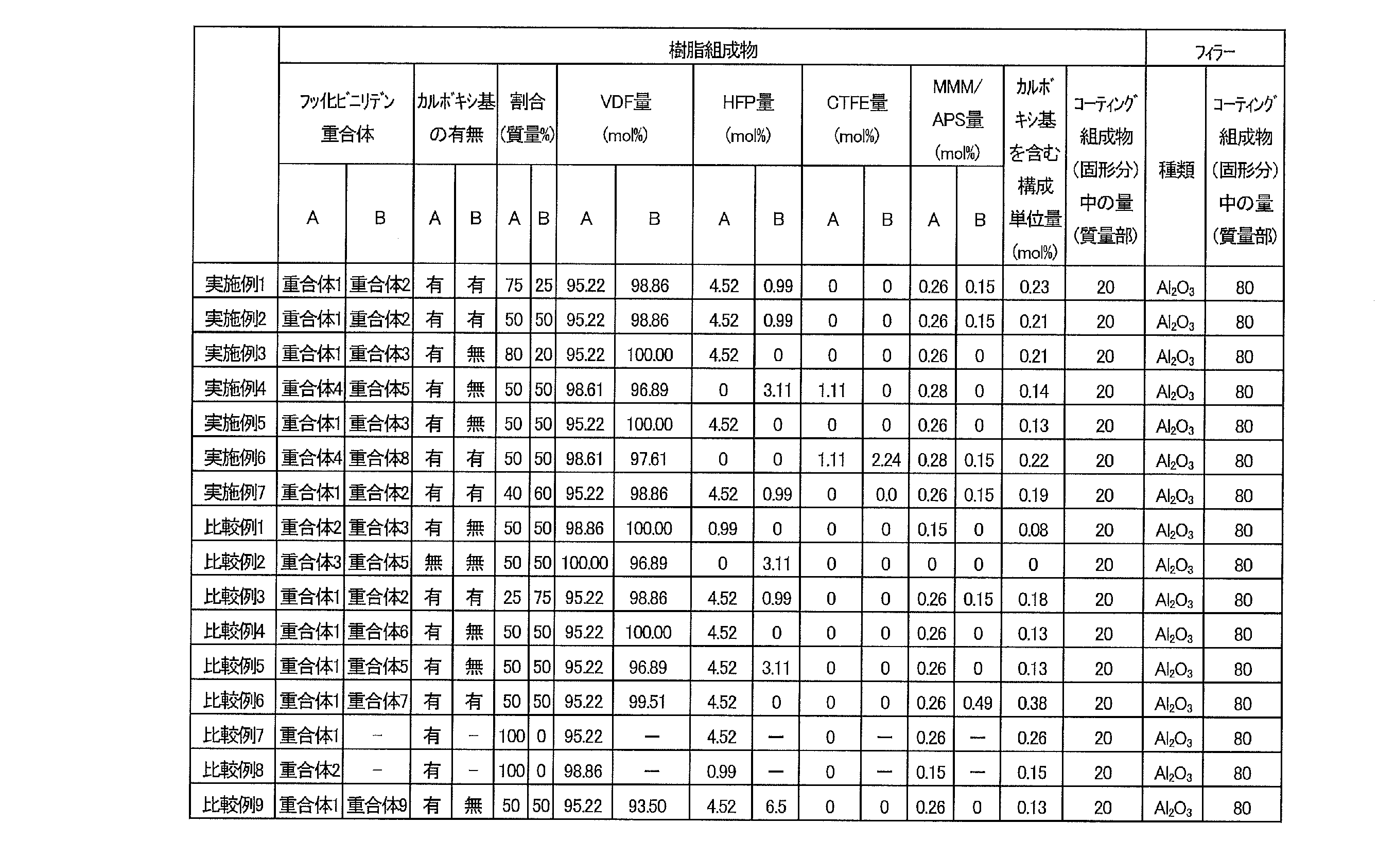

上記表2に示されるように、樹脂組成物が、2種のフッ化ビニリデン重合体を含み、かつ樹脂組成物の全融解熱量が20J/g以上50J/g以下であり、固有粘度が2.5dL/g以下である場合には、ウェット接着およびドライ接着の評価結果が良好であり、かつプロセスウィンドウも10℃以上であった(実施例1~7)。
これに対し、樹脂組成物が、1種のフッ化ビニリデン重合体しか含まない場合には、上記全融解熱量や固有粘度、吸光度比を満たしたとしても、ウェット接着性が低く、さらにプロセスウィンドウが狭かった(比較例7)。また、樹脂組成物が2種のフッ化ビニリデン重合体を含み、上記各物性を満たしたとしても、いずれかのフッ化ビニリデン重合体が含むフッ化ビニリデンの量が少ない場合には、ウェット接着性が低く、かつプロセスウィンドウが低かった(比較例9)。
また、全融解熱量が20J/gを下回る場合には、ウェット接着性が低下する傾向にあった(比較例5)。一方、全融解熱量が50J/gを上回る場合には、ドライ接着性またはウェット接着性のいずれかが低かった(比較例1、4、6、8)。さらに、カルボキシ基を含まない場合には、ドライ接着性が低下する傾向があった(比較例2)。さらに、樹脂組成物の固有粘度が2.5dL/gを上回る場合にも、ドライ接着性が低下した(比較例1、3、および8)。
本出願は、2020年8月28日出願の特願2020-144549号に基づく優先権を主張する。当該出願明細書に記載された内容は、すべて本願明細書に援用される。
本発明の樹脂組成物は、ドライ接着性およびウェット接着性の両方に優れ、かつ比較的広い温度範囲でウェット接着可能である。したがって、二次電池用の電極の作製等において非常に有用である。
Claims (11)
- フッ化ビニリデン重合体を2種以上含む樹脂組成物であって、
複数の前記フッ化ビニリデン重合体のうち、少なくとも1種が、カルボキシ基を含む構成単位を含み、
複数の前記フッ化ビニリデン重合体がいずれも、フッ化ビニリデンに由来する構成単位を構成単位全量に対して95モル%以上含み、
前記樹脂組成物の示差走査熱量測定の昇温2回目における全融解熱量が20J/g以上50J/g以下であり、
前記樹脂組成物の固有粘度が2.5dL/g以下である、樹脂組成物。 - 前記樹脂組成物に含まれる、カルボキシ基を含む構成単位が、構成単位全量に対して0.05モル%以上0.5モル%以下である、
請求項1に記載の樹脂組成物。 - 前記樹脂組成物の1740cm-1における赤外吸収スペクトルの吸光度A1740と3020cm-1における赤外吸収スペクトルの吸光度A3020との比A1740/A3020が0.15以上である、
請求項1または2に記載の樹脂組成物。 - 前記カルボキシ基を含む構成単位が、
不飽和二塩基酸に由来する構成単位、不飽和二塩基酸モノエステルに由来する構成単位、および下記一般式(1)で表される化合物に由来する構成単位、からなる群から選ばれる、少なくとも1つの基である、
請求項1~3のいずれか一項に記載の樹脂組成物。

- 複数の前記フッ化ビニリデン重合体のうち、少なくとも一種が、クロロトリフルオロエチレンまたはヘキサフルオロプロピレン由来の構成単位をさらに含む、
請求項1~4に記載の樹脂組成物。 - 請求項1~5のいずれか一項に記載の樹脂組成物と、溶媒と、を含む、
コーティング組成物。 - フィラーをさらに含む、
請求項6に記載のコーティング組成物。 - 電極と、
前記電極の少なくとも一方の面に配置された、請求項1~5のいずれか一項に記載の樹脂組成物を含む樹脂含有層と、
を有する、積層用電極。 - セパレータと、
前記セパレータの少なくとも一方の面に配置された、請求項1~5のいずれか一項に記載の樹脂組成物を含む樹脂含有層と、
を有する、積層用セパレータ。 - 正極と、セパレータと、負極と、を含み、
前記正極と前記セパレータとの間、および/または前記負極と前記セパレータとの間に、請求項1~5のいずれか一項に記載の樹脂組成物を含む樹脂含有層をさらに有する、
非水電解質二次電池。 - 正極、セパレータ、および負極からなる群から選ばれる少なくとも1つの部材の、少なくとも一方の面に、請求項6または7に記載のコーティング組成物を塗布し、固化させて樹脂含有層を形成する工程と、
前記樹脂含有層が、前記正極および前記セパレータの間に位置する、および/または前記負極および前記セパレータの間に位置するように、前記正極、前記セパレータ、および前記負極を積層して積層体を形成する工程と、
前記積層体を熱プレスする工程と、
を有する、非水電解質二次電池の製造方法。
Applications Claiming Priority (2)
| Application Number | Priority Date | Filing Date | Title |
|---|---|---|---|
| JP2020-144549 | 2020-08-28 | ||
| JP2020144549 | 2020-08-28 |
Publications (1)
| Publication Number | Publication Date |
|---|---|
| WO2022044592A1 true WO2022044592A1 (ja) | 2022-03-03 |
Family
ID=80353204
Family Applications (1)
| Application Number | Title | Priority Date | Filing Date |
|---|---|---|---|
| PCT/JP2021/026409 Ceased WO2022044592A1 (ja) | 2020-08-28 | 2021-07-14 | 樹脂組成物およびこれを含むコーティング組成物、積層用電極、積層用セパレータ、ならびに非水電解質二次電池およびその製造方法 |
Country Status (1)
| Country | Link |
|---|---|
| WO (1) | WO2022044592A1 (ja) |
Cited By (1)
| Publication number | Priority date | Publication date | Assignee | Title |
|---|---|---|---|---|
| JP2024542289A (ja) * | 2021-12-28 | 2024-11-13 | 株式会社クレハ | バインダー、電極合剤、および電極 |
Citations (4)
| Publication number | Priority date | Publication date | Assignee | Title |
|---|---|---|---|---|
| WO2013058368A1 (ja) * | 2011-10-21 | 2013-04-25 | 帝人株式会社 | 非水系二次電池用セパレータ及び非水系二次電池 |
| WO2018124176A1 (ja) * | 2016-12-27 | 2018-07-05 | 東レ株式会社 | 電池用セパレータ、電極体及び非水電解質二次電池 |
| WO2019107521A1 (ja) * | 2017-11-30 | 2019-06-06 | 帝人株式会社 | 非水系二次電池用セパレータ及び非水系二次電池 |
| JP2020113442A (ja) * | 2019-01-11 | 2020-07-27 | カーリットホールディングス株式会社 | 非水電解質二次電池用電極 |
-
2021
- 2021-07-14 WO PCT/JP2021/026409 patent/WO2022044592A1/ja not_active Ceased
Patent Citations (4)
| Publication number | Priority date | Publication date | Assignee | Title |
|---|---|---|---|---|
| WO2013058368A1 (ja) * | 2011-10-21 | 2013-04-25 | 帝人株式会社 | 非水系二次電池用セパレータ及び非水系二次電池 |
| WO2018124176A1 (ja) * | 2016-12-27 | 2018-07-05 | 東レ株式会社 | 電池用セパレータ、電極体及び非水電解質二次電池 |
| WO2019107521A1 (ja) * | 2017-11-30 | 2019-06-06 | 帝人株式会社 | 非水系二次電池用セパレータ及び非水系二次電池 |
| JP2020113442A (ja) * | 2019-01-11 | 2020-07-27 | カーリットホールディングス株式会社 | 非水電解質二次電池用電極 |
Cited By (2)
| Publication number | Priority date | Publication date | Assignee | Title |
|---|---|---|---|---|
| JP2024542289A (ja) * | 2021-12-28 | 2024-11-13 | 株式会社クレハ | バインダー、電極合剤、および電極 |
| JP7747908B2 (ja) | 2021-12-28 | 2025-10-01 | 株式会社クレハ | バインダー、電極合剤、および電極 |
Similar Documents
| Publication | Publication Date | Title |
|---|---|---|
| JP6764468B2 (ja) | 接着層を含む電気化学素子用の複合分離膜及びこれを備えた電気化学素子 | |
| JP6487134B1 (ja) | 非水系二次電池用セパレータ、および非水系二次電池 | |
| US7851084B2 (en) | Vinylidene fluoride based core-shell type polymer and use thereof in nonaqueous electrochemical device | |
| KR102063594B1 (ko) | 비수계 이차전지용 세퍼레이터 및 비수계 이차전지 | |
| CN103947009B (zh) | 非水系二次电池用隔膜及其制造方法以及非水系二次电池 | |
| TWI553944B (zh) | 非水系蓄電池用分隔器及非水系蓄電池 | |
| KR20200030492A (ko) | 전기화학소자용 세퍼레이터 및 이의 제조방법 | |
| JP6891346B2 (ja) | 接着性組成物、セパレータ構造体、電極構造体、非水電解質二次電池およびその製造方法 | |
| CN110622339B (zh) | 非水系二次电池用隔膜、非水系二次电池及非水系二次电池的制造方法 | |
| US10074841B2 (en) | Structure for non-aqueous electrolyte secondary battery, non-aqueous electrolyte secondary battery, and method for manufacturing same structure | |
| CN108448033A (zh) | 非水系二次电池用隔膜和非水系二次电池 | |
| KR102067145B1 (ko) | 무기 코팅층을 포함하는 전기화학소자용 분리막 및 이를 제조하는 방법 | |
| JP6371905B2 (ja) | 非水系二次電池用セパレータ及び非水系二次電池 | |
| JP6955355B2 (ja) | コアシェル型粒子ならびにその用途および製造方法 | |
| JP2018133244A (ja) | 非水系二次電池用セパレータ、および、非水系二次電池 | |
| JP7445772B2 (ja) | 樹脂組成物およびこれを含むコーティング組成物、積層用電極、積層用セパレータ、ならびに非水電解質二次電池およびその製造方法 | |
| JP2018133245A (ja) | 非水系二次電池用セパレータ、および、非水系二次電池 | |
| WO2022025081A1 (ja) | 非水系二次電池 | |
| JP7313582B2 (ja) | 非水系二次電池用セパレータ及び非水系二次電池 | |
| KR20250179114A (ko) | 전극 합제 시트, 전극, 이차 전지 및 전극 합제 시트의 제조 방법 |
Legal Events
| Date | Code | Title | Description |
|---|---|---|---|
| 121 | Ep: the epo has been informed by wipo that ep was designated in this application |
Ref document number: 21861021 Country of ref document: EP Kind code of ref document: A1 |
|
| NENP | Non-entry into the national phase |
Ref country code: DE |
|
| 122 | Ep: pct application non-entry in european phase |
Ref document number: 21861021 Country of ref document: EP Kind code of ref document: A1 |
|
| NENP | Non-entry into the national phase |
Ref country code: JP |