WO2022044232A1 - ゲートウェイ装置、ネットワーク制御装置、方法、プログラム及びシステム - Google Patents
ゲートウェイ装置、ネットワーク制御装置、方法、プログラム及びシステム Download PDFInfo
- Publication number
- WO2022044232A1 WO2022044232A1 PCT/JP2020/032484 JP2020032484W WO2022044232A1 WO 2022044232 A1 WO2022044232 A1 WO 2022044232A1 JP 2020032484 W JP2020032484 W JP 2020032484W WO 2022044232 A1 WO2022044232 A1 WO 2022044232A1
- Authority
- WO
- WIPO (PCT)
- Prior art keywords
- domain
- route
- packet
- destination
- forwarding
- Prior art date
- Legal status (The legal status is an assumption and is not a legal conclusion. Google has not performed a legal analysis and makes no representation as to the accuracy of the status listed.)
- Ceased
Links
Images




Classifications
-
- H—ELECTRICITY
- H04—ELECTRIC COMMUNICATION TECHNIQUE
- H04W—WIRELESS COMMUNICATION NETWORKS
- H04W48/00—Access restriction; Network selection; Access point selection
- H04W48/18—Selecting a network or a communication service
-
- H—ELECTRICITY
- H04—ELECTRIC COMMUNICATION TECHNIQUE
- H04L—TRANSMISSION OF DIGITAL INFORMATION, e.g. TELEGRAPHIC COMMUNICATION
- H04L45/00—Routing or path finding of packets in data switching networks
- H04L45/12—Shortest path evaluation
- H04L45/121—Shortest path evaluation by minimising delays
-
- H—ELECTRICITY
- H04—ELECTRIC COMMUNICATION TECHNIQUE
- H04L—TRANSMISSION OF DIGITAL INFORMATION, e.g. TELEGRAPHIC COMMUNICATION
- H04L45/00—Routing or path finding of packets in data switching networks
- H04L45/12—Shortest path evaluation
- H04L45/125—Shortest path evaluation based on throughput or bandwidth
-
- H—ELECTRICITY
- H04—ELECTRIC COMMUNICATION TECHNIQUE
- H04W—WIRELESS COMMUNICATION NETWORKS
- H04W40/00—Communication routing or communication path finding
- H04W40/02—Communication route or path selection, e.g. power-based or shortest path routing
- H04W40/12—Communication route or path selection, e.g. power-based or shortest path routing based on transmission quality or channel quality
-
- H—ELECTRICITY
- H04—ELECTRIC COMMUNICATION TECHNIQUE
- H04L—TRANSMISSION OF DIGITAL INFORMATION, e.g. TELEGRAPHIC COMMUNICATION
- H04L12/00—Data switching networks
- H04L12/28—Data switching networks characterised by path configuration, e.g. LAN [Local Area Networks] or WAN [Wide Area Networks]
- H04L12/46—Interconnection of networks
- H04L12/4633—Interconnection of networks using encapsulation techniques, e.g. tunneling
-
- H—ELECTRICITY
- H04—ELECTRIC COMMUNICATION TECHNIQUE
- H04L—TRANSMISSION OF DIGITAL INFORMATION, e.g. TELEGRAPHIC COMMUNICATION
- H04L41/00—Arrangements for maintenance, administration or management of data switching networks, e.g. of packet switching networks
- H04L41/40—Arrangements for maintenance, administration or management of data switching networks, e.g. of packet switching networks using virtualisation of network functions or resources, e.g. SDN or NFV entities
-
- H—ELECTRICITY
- H04—ELECTRIC COMMUNICATION TECHNIQUE
- H04L—TRANSMISSION OF DIGITAL INFORMATION, e.g. TELEGRAPHIC COMMUNICATION
- H04L43/00—Arrangements for monitoring or testing data switching networks
- H04L43/02—Capturing of monitoring data
- H04L43/026—Capturing of monitoring data using flow identification
-
- H—ELECTRICITY
- H04—ELECTRIC COMMUNICATION TECHNIQUE
- H04W—WIRELESS COMMUNICATION NETWORKS
- H04W88/00—Devices specially adapted for wireless communication networks, e.g. terminals, base stations or access point devices
- H04W88/16—Gateway arrangements
Definitions
- the present invention relates to a gateway device, a network control device, a method, a program and a system.
- the 5th generation mobile communication system (5G: 5th Generation) has been put into practical use.
- 5G 5th Generation
- the network slicing technology is known as a technology for providing a network quickly and flexibly in response to such a demand.
- network slicing technology it is possible to manage the infrastructure of common physical equipment as virtually divisible resources and freely combine those resources to build the required virtual network (slice).
- an E2E slice that can ensure a certain level of communication quality with E2E (End-to-End) is required.
- This E2E slice is not necessarily a NW closed within a single NW operator / domain, and may be a NW that spans a plurality of NW operators / domains.
- a slice gateway (SLG: Slice Gateway) is used at the connection point between each NW operator / domain. ) Has been proposed.
- Non-Patent Document 1 a method of realizing slicing by the NW configuration shown in FIG. 1 is known (for example, Non-Patent Document 1).
- the NW configuration shown in FIG. 1 includes an access NW, a core NW, and a NW in a DC (data center), and an SLG is deployed at a connection point of each NW.
- tunnels for each type shared by multiple slices for example, the type determined by the transfer priority, the presence or absence of redundancy, etc.
- the tunnels in each domain are set according to the slice requirements.
- Slices that is, virtual tunnels between the terminal and the server / VM (Virtual Machine)
- VM Virtual Machine
- bandwidth guarantee and highly reliable slice can be realized by connecting tunnels with priority and route redundancy.
- the tunnel 1 of the access NW, the tunnel 5 of the core NW, and the tunnel 13 of the NW in the DC are connected, or the tunnel 3 of the access NW, the tunnel 9 of the core NW, and the tunnel 13 of the NW in the DC are connected. It can be realized by doing things such as tunneling.
- bandwidth guarantee / highly reliable slice via NF Network Function
- Firewall can be realized by connecting tunnels with priority / route redundancy via NF.
- the tunnel 1 of the access NW, the tunnel 7 of the core NW, and the tunnel 13 of the NW in the DC are connected, or the tunnel 3 of the access NW, the tunnel 11 of the core NW, and the tunnel 16 of the NW in the DC are connected. It can be realized by doing things such as tunneling.
- BE best effort
- highly reliable slices can be realized by connecting tunnels with BE and route redundancy.
- the tunnel 2 of the access NW, the tunnel 6 of the core NW, and the tunnel 14 of the NW in the DC are connected, or the tunnel 4 of the access NW, the tunnel 10 of the core NW, and the tunnel 17 of the NW in the DC are connected.
- BE, low-reliability slices, etc. are also realized by appropriately connecting tunnels to each other.
- an application is mounted on the terminal, and various services are provided to the terminal by application processing executed by the server / VM.
- Non-Patent Document 1 information indicating transfer requirements such as packet transfer priority and the necessity of route redundancy necessary for satisfying service requirements, an ID of an edge SLG to be a ground, and a NW.
- the slice is realized by adding information uniquely indicating the slice for separation to the header of the packet.
- the edge SLG is an edge deployed at the edge of the domain, and SLGs other than the edge SLG are also called relay SLGs. Further, the edge SLG to be the ground is an edge SLG to which the packet is transmitted.
- Non-Patent Document 1 assumes a simple NW configuration in which domains are linearly connected, if the number of connected domains increases and the NW configuration becomes complicated in terms of area, The transfer table set in each SLG increases, and the processing load of the SLG may increase, the transfer performance may deteriorate, and the like.
- the forwarding table is a table for determining the output destination tunnel of the packet.
- One embodiment of the present invention has been made in view of the above points, and an object thereof is to suppress an increase in the transfer table of the SLG that realizes an E2E slice.
- the gateway device has a packet to which a header including a slice requirement indicating a packet forwarding requirement and a destination domain ID indicating a destination domain of the packet is added.
- the forwarding destination specifying unit for specifying the tunnel corresponding to the slice requirement and the destination domain ID and the forwarding destination specifying unit refer to the forwarding table for determining the forwarding destination tunnel of the packet. It is characterized by having a forwarding unit that outputs the packet to the specified tunnel.
- a NW controller (denoted as “NW Ctrl” in FIG. 2) and an SGL are deployed in each domain.
- “A1” to “a3”, “c1” to “c3”, “A1”, “B1” to “B2”, and “C1” in FIG. 2 represent SLG IDs.
- the NW controller is a device, device, program, or the like that manages various settings (including a transfer table) of a NW device such as an SLG.
- a terminal, a server / VM, or an application process executed by these is represented as a slice end point.
- a slice end point there are four slice endpoints from slice A endpoint to slice D endpoint, and the transfer requirements for each are "low delay”, "broadband”, “BE (best effort) / redundancy available", and " There is no BE / redundancy.
- the tunnel ID of the tunnel between each SLG shall be represented in the format of "SLG ID of SLG on the left side + SLG ID-1 to 3 of SLG on the right side", and the last "1" is the highest priority transfer path, " "2" represents a priority transfer path, and "3” represents a BE path.
- the tunnel ID of the tunnel that is the highest priority transfer path is "a1A1-1", priority transfer.
- the tunnel ID of the tunnel that is the path is expressed as "a1A1-2”
- the tunnel ID of the tunnel that is the BE path is expressed as "a1A1-3”.
- a route learning process of learning a route by cooperation between NW controllers and setting a forwarding table in each SLG and a forwarding process of forwarding a packet by the forwarding table set in each SLG are executed.
- an example of the route learning process will be described in S11 to S13, and an example of the transfer process will be described in S21 to S23.
- the NW controller of each domain notifies the NW controller of the adjacent domain of the SLG ID of the edge SLG deployed in its own domain.
- the NW controller of the domain C notifies the NW controller of the domain B of the SLG IDs “c1” to “c3” is shown.
- each NW controller propagates the SLG ID to the NW controller of the adjacent domain other than the adjacent domain.
- the example shown in FIG. 2 shows a case where the NW controller of domain B propagates the SLG IDs “c1” to “c3” to the NW controller of domain A.
- each NW controller has the SLG ID of the SLG ID deployed in its own domain based on the SLG ID and the notification source domain.
- the example shown in FIG. 2 shows a case where the NW controller of the domain A sets a forwarding table for transmitting a packet to the edge SLGs of the SLG IDs “c1” to “c3” for the SLG in the own domain. There is.
- FIG. 3 shows an example of the transfer table set in the edge SLG of the SLG ID “a1”.
- the SLG ID of the packet transmission destination in the forwarding table, the SLG ID of the packet transmission destination, the forwarding priority, the presence / absence of redundancy, and the tunnel ID of the output destination tunnel are associated with each other.
- "* (asterisk)" represents a wild card.
- the transfer priority is "highest priority”, and the redundancy is "*", the output destination tunnel is "*". It means that it is "a1A1-1”.
- the transfer priority is "priority”, and the redundancy is "*”, it means that the output destination tunnel is "a1A1-2”.
- the transfer table may be associated with, for example, whether or not NF is used.
- the edge SLG of each domain adds a slice-only header to the packet.
- the information indicating the forwarding requirement such as the forwarding priority of the packet required to satisfy the service requirement and the necessity of redundancy, the SLG ID of the edge SLG to be the ground, and the SLG ID of the ground SLG are used.
- Information uniquely indicating a slice hereinafter referred to as "slice ID" or “slice identification information" is defined as a slice-dedicated header.
- each relay SLG in each domain receives a packet forwarded from another relay SLG, it refers to the forwarding table set in itself and determines an appropriate output destination tunnel from the slice-only header of the packet. And forward the packet.
- the edge SLG receives the packet transferred from the relay SLG, it refers to the slice identification information included in the slice-dedicated header of the packet, then deletes the slice-dedicated header and deletes the appropriate slice end point (that is, that is). , The slice end point corresponding to the slice identification information), the packet is output.
- the E2E slice is realized in the conventional method.
- the transfer table since the transfer table is set for each edge SLG, the transfer table increases as the NW scale increases, such as an increase in the number of connection domains and an increase in the number of SLGs. Therefore, an increase in the load of each SLG, deterioration of transfer performance, and the like may occur.
- each NW controller needs to perform a route learning process for updating the transfer table every time an expansion or reduction of an edge SLG occurs, and the frequency increases as the number of domains increases, so that each NW The load on the controller increases.
- the route learning is performed by exchanging the SLG ID of the edge SLG between the NW controllers of each domain, but when there are a plurality of routes addressed to the same edge SLG, the route is performed. It was not possible to determine the optimum route in consideration of differences in the number of transit domains, path specifications (for example, QoS class, presence / absence of redundancy, etc.), quality (for example, bandwidth, delay, etc.), etc. for each route. For example, as shown in FIG. 4, there are a plurality of routes from the edge SLG of domain A to the edge SLG of domain G, but the number of transit domains, path specifications, quality, and the like are different.
- the number of transit domains differs between the route via domain B and domain C and the route via domain D.
- the route via domain B and domain C and the route via domain E and domain F have the same number of transit domains, but the route via domain B and domain C is redundant.
- routes via domain E and domain F While supporting routes of various qualities, routes via domain E and domain F only support BE / no route redundancy, and their path specifications and qualities are different.
- the NW configuration becomes complicated in terms of surface, and in the conventional method, there are problems such as (1) an increase in the load of the SLG, a decrease in transfer performance, and an increase in the load of the NW controller. 2)
- the optimum route cannot be determined in consideration of the number of transit domains, path specifications, quality, and the like.
- the transfer table according to the present embodiment is associated with information uniquely indicating a domain (hereinafter referred to as "domain ID"), not an SLG ID, as a packet transmission destination.
- domain ID information uniquely indicating a domain
- FIG. 6 shows a transfer table set in the edge SLG of the SLG ID “a1”.
- a domain ID is used as the transmission destination instead of the SLG ID.
- "1" and "0" in redundancy represent the existence of redundancy and the absence of redundancy, respectively.
- the edge SLG of each domain adds a slice-only header to the packet.
- the information indicating the forwarding requirement that is, the slicing requirement
- the forwarding priority such as the forwarding priority and the necessity of redundancy of the packet required to satisfy the service requirement
- the domain ID of the destination domain and the slice.
- Identification information is defined as a slice-only header. That is, the slice-only header according to the present embodiment uses the domain ID of the destination domain instead of the SLG ID of the edge SLG that serves as the ground.
- each relay SLG of each domain other than the destination domain receives a packet forwarded from another relay SLG, it refers to the forwarding table set in itself and is appropriate from the slice-only header of the packet.
- the output destination tunnel is determined and the packet is forwarded.
- each relay SLG of the destination domain receives a packet transferred from another relay SLG, it is included in the slice identification information and other information (for example, the header of the packet) included in the slice-only header of the packet.
- the packet is forwarded to the corresponding edge SLG in the own domain based on the destination IP address, etc.).
- the edge SLG receives the packet transferred from the relay SLG, it refers to the slice identification information included in the slice-dedicated header of the packet, and then deletes the slice-dedicated header to obtain an appropriate slice endpoint (that is, that is). , The slice end point corresponding to the slice identification information), the packet is output. As a result, an E2E slice is realized.
- the packet transfer is performed by designating the domain ID, which is a larger unit, instead of designating the SLG ID as the destination.
- a transfer table in which a domain ID is specified as a destination is set in each SLG. This makes it possible to conceal the edge SLG in each domain, suppress the increase in the transfer table, suppress the load increase of the SLG and the deterioration of the transfer performance, and the NW controller due to the expansion / reduction of the edge SLG. It is possible to suppress the increase in load.
- the NW controller of each domain advertises (notifies) the domain ID of its own domain to the NW controller of the adjacent domain as the destination domain ID.
- the NW controller of the domain G advertises the domain ID “G” to the NW controller of the domain C, the NW controller of the domain D, and the NW controller of the domain F is shown.
- the destination domain ID means that the domain ID is the destination of the packet.
- each NW controller advertises the route information to the NW controller of the adjacent domain other than the adjacent domain.
- This route information includes the destination domain ID, the transit domain ID indicating the domain ID of the own domain, the relay SLG of the own domain adjacent to the advertisement destination domain, and the relay SLG of the notification source domain of the destination domain ID. It includes the path specs supported by the route in the section between and the quality information for each pass spec (eg, band and delay, etc.).
- the destination domain ID “G”, the transit domain ID “F”, the path spec “BE / redundancy”, the band “20 Gbps”, and the delay “10 msec” are included in the route information. Is shown.
- This path spec, band and delay are supported by the route between the relay SLG in the domain F adjacent to the domain E and the relay SLG in the domain G adjacent to the domain F.
- the path specs supported by a certain route and the quality information for each path spec are the path specifications that can be provided by the route and the quality information for each of these path specifications.
- each NW controller stores the route information in the inter-domain connection table, adds the domain ID of its own domain to the transit domain ID, and if necessary. After updating the path specifications and quality information, the route information is advertised to the NW controller of the adjacent domain other than the adjacent domain.
- the path specifications included in the notified route information are "highest priority / redundancy” and "BE / redundancy”.
- the path spec supported by the route between the relay SLG of the own domain adjacent to the advertisement destination domain and the relay SLG of the notification source domain of the route information is "BE / redundancy”.
- the path spec of the route information is updated to "BE / with redundancy” (that is, in this case, "highest priority / with redundancy” and its quality information (bandwidth, delay) are deleted from the route information). ..
- the path spec included in the notified route information is "highest priority / redundancy", and the relay SLG of the own domain adjacent to the advertisement destination domain and the relay SLG of the notification source domain of the route information If the path spec supported by the route in the interval is "highest priority / no redundancy", the path spec of the route information is updated to "highest priority / no redundancy”.
- the band of a certain path spec included in the notified route information is "20 Gbps" and the band of the path spec of the section is "10 Gbps”
- the band included in the route information is said to be included.
- the bandwidth of the path spec is updated to "10 Gbps".
- FIG. 8 shows an example of the inter-domain connection table held by the NW controller of domain A.
- the inter-domain connection table according to the present embodiment is a table in which route information notified from the NW controller of the adjacent domain is stored.
- each NW controller manages the path specifications and quality information of the transit domain to the destination domain and the route to the destination domain in the inter-domain connection table. This makes it possible to set a forwarding table for each SLG to select the optimum route in consideration of the number of transit domains, path specifications, and quality information.
- the NW controller of each domain sets a forwarding table for transmitting a packet to each domain ID for the SLG in its own domain based on the inter-domain connection table held by itself.
- the NW controller of each domain selects the route information according to the transfer requirement to be satisfied by the slice, considering the path specifications and quality information of the route to the destination domain and the route to the destination domain. Therefore, each SLG has a forwarding table in which the destination domain ID included in the route information is the destination domain ID, the path spec is the forwarding priority, and the tunnel for forwarding the packet to the first transit domain ID is the output destination domain. Set to.
- a transfer table that realizes slicing with the optimum route considering the number of transit domains, path specifications, and quality information is set for each SLG.
- route information should be selected according to the transfer requirements to be satisfied by the slice can be considered in various ways, and various selection methods can be adopted for each domain.
- An example of a method of selecting route information will be described below with reference to the inter-domain connection table shown in FIG.
- Slice A in FIG. 7 is a "low delay slice”. Therefore, when setting the transfer information (one record in the transfer table) used when using slice A, for example, among the route information stored in the interdomain connection table shown in FIG. 8, for example, Select the route information with the least delay (route information on the fourth line from the top).
- Slice B in FIG. 7 is a "wideband slice". Therefore, when setting the transfer information used when using slice B, for example, among the route information stored in the interdomain connection table shown in FIG. 8, the route information having the largest bandwidth (from above). Select the route information on the second line).
- Slice C in FIG. 7 is "BE slice / with redundancy". Therefore, when setting the transfer information used when using slice C, for example, among the route information stored in the interdomain connection table shown in FIG. 8, the bandwidth is the largest with BE and redundancy. Select a large route information (route information on the third line from the top).
- Slice D in FIG. 7 is "BE slice / no redundancy". Therefore, when setting the transfer information used when using the slice D, for example, among the route information stored in the interdomain connection table shown in FIG. 8, the route information that is BE and has no redundancy (the route information without redundancy) Select the route information on the 7th line from the top).
- each NW controller compares the route information to be advertised to the adjacent domain with the route information advertised from the adjacent domain to the own domain. , If the following conditions are met, the route information of the advertisement target will not be advertised to the adjacent domain.
- the number of transit domains (including own domain) included in the route information to be advertised to the adjacent domain is included in the route information advertised from the adjacent domain. More than the number of transit domains.
- the route information notified from the NW controller of domain B is already stored in the inter-domain connection table held by the NW controller of domain A.
- the NW controller of the domain A does not notify (advertise) the route information to the NW controller of the domain B.
- the number of transit domains included in the route information of the advertisement target to the domain B generated by the NW controller of the domain A based on the route information advertised from the domain D is 2. This is because the number of transit domains included in the route information advertised by the NW controller of domain B is also 2, which satisfies the above conditions.
- the NW controller 10 has a quality control unit 101 and a route calculation unit 102.
- Each of these functional units is realized by hardware such as a processor and a memory device.
- the quality control unit 101 has specifications of paths between the edge SLG20 and the relay SLG30 in the own domain, between the relay SLG30 and the relay SLG30, and between the relay SLG30 in the own domain and the relay SLG30 in the adjacent domain (transfer priority, presence / absence of redundancy, etc.). ) And quality information for each path (available band, delay, etc.).
- the route calculation unit 102 advertises the domain ID of its own domain to the adjacent domain as the destination domain ID.
- the route calculation unit 102 when the destination domain ID is advertised (notified) by the NW controller 10 of the adjacent domain, the route calculation unit 102 includes the destination domain ID for the NW controller 10 of the adjacent domain other than the adjacent domain. Advertise route information. At this time, the route calculation unit 102 sets the own domain ID as the transit domain ID in the route information, and based on the information held by the quality control unit 101, the route calculation unit 102 relays within the own domain adjacent to the advertisement destination domain.
- the path specs supported by the route between the SLG30 and the relay SLG30 of the notification source domain of the destination domain ID and the quality information (bandwidth, delay, etc.) for each path spec are set in the route information.
- the route calculation unit 102 stores the route information in the inter-domain connection table and adds the domain ID of its own domain to the transit domain ID. Then, after updating the path specifications and quality information as necessary based on the information held by the quality control unit 101, the route information is advertised to the NW controller 10 of the adjacent domain other than the adjacent domain.
- the route calculation unit 102 holds an inter-domain connection table, and sets a transfer table for the edge SLG20 and the relay SLG30 in the own domain based on the route information stored in the inter-domain connection table.
- the edge SLG20 has a header setting unit 201 and a transfer processing unit 202.
- Each of these functional units is realized by hardware such as a processor and a memory device.
- the header setting unit 201 is used for 5-double information (source IP address, destination IP address, source port number, destination port number and protocol number) of the packet input from the slice end point, input I / F information, and the like. Based on this, the slice to which the packet belongs is identified. Then, the header setting unit 201 adds the slice requirement, the domain ID of the destination, and the slice identification information to the packet as a slice-only header based on the identification result. In the present embodiment, when the header setting unit 201 adds the slice-dedicated header to the packet, it is assumed that the slice requirement, the domain ID of the destination, and the slice identification information are known.
- the header setting unit 201 refers to the slice identification information of the slice-dedicated header given to the packet input from the relay SLG30, deletes the slice-dedicated header, and outputs the packet to an appropriate slice end point. do.
- the transfer processing unit 202 holds a transfer table, refers to this transfer table, determines a destination domain ID included in the slice-only header of the packet, and an output destination tunnel that matches the transfer requirement, and sets the output destination tunnel to the output destination tunnel. Output a packet.
- the relay SLG30 has a transfer processing unit 301.
- This functional unit is realized by hardware such as a processor and a memory device.
- the forwarding processing unit 301 holds the forwarding table, refers to this forwarding table, determines the destination domain ID included in the slice-only header of the packet, and the output destination tunnel that matches the forwarding requirement, and sets the output destination tunnel to the destination tunnel. Output a packet.
- the transfer processing unit 301 when the destination domain ID included in the slice-dedicated header of the packet is the own domain ID, the transfer processing unit 301 includes the slice identification information included in the slice-dedicated header and 5-included in the header of the packet.
- the edge SLG20 to which the packet should reach is specified based on the tuple information or the like. Then, the transfer processing unit 301 outputs a packet to the specified edge SLG20 using a path that satisfies the transfer requirement included in the slice-dedicated header.
- the conditions for specifying the edge SLG20 above are set by, for example, the NW controller 10, and are known in the present embodiment.
- the route calculation unit 102 of the NW controller 10 of each domain advertises (notifies) the domain ID of its own domain to the NW controller of the adjacent domain as the destination domain ID.
- the route calculation unit 102 of each NW controller 10 advertises the route information to the NW controller 10 of the adjacent domain other than the adjacent domain.
- This route information includes the destination domain ID, the transit domain ID indicating the domain ID of the own domain, the relay SLG of the own domain adjacent to the advertisement destination domain, and the relay SLG of the notification source domain of the destination domain ID. It includes the path specs supported by the route in the section between and the quality information for each pass spec (eg, band and delay, etc.). Of these, the path spec and the quality information for each pass spec use the information held by the quality control unit 101 of the NW controller 10 that advertises the route information.
- the route calculation unit 102 of each NW controller 10 stores the route information in the inter-domain connection table and stores the domain ID of its own domain in the transit domain ID. Is added, the path specifications and quality information are updated as necessary, and then the route information is advertised to the NW controller 10 of the adjacent domain other than the adjacent domain.
- the update of the path spec and the quality information is performed by updating the path spec and the quality information held by the quality control unit 101 of the NW controller 10 that advertises the route information, and the path spec and the quality information included in the notified route information. And are used to update according to (A) to (C) above.
- the route calculation unit 102 does not advertise the route information to the adjacent domain when the above conditions are satisfied so that the route information loop does not occur.
- the route calculation unit 102 of the NW controller 10 of each domain sets a transfer table for the edge SLG20 and the relay SLG30 in its own domain based on the inter-domain connection table held by itself.
- the header setting unit 201 of the edge SLG20 of each domain identifies the slice to which the packet belongs based on the 5-tuple information of the packet, the input I / F information, and the like. do. Then, the header setting unit 201 adds (assigns) a slice-only header to the packet based on the identification result.
- the transfer processing unit 301 of each relay SLG30 of each domain other than the destination domain receives the packet transferred from the other relay SLG30, the transfer processing unit 301 refers to the transfer table set in itself and slices the packet. The appropriate output destination tunnel is determined from the dedicated header and the packet is forwarded.
- each relay SLG30 of the destination domain receives the packet transferred from the other relay SLG30, the slice identification information included in the slice-dedicated header of the packet and the slice identification information included in the header of the packet 5 -The packet is transferred to the corresponding edge SLG20 in the own domain based on the tuple information or the like.
- the transfer processing unit 202 of the edge SLG20 receives the packet transferred from the relay SLG30, the slice identification information included in the slice-dedicated header of the packet is referred to, and then the slice-dedicated header is deleted and appropriate. The packet is output to the slice endpoint.
- the NW controller 10 includes an input device 401, a display device 402, an external I / F 403, a communication I / F 404, a processor 405, and a memory device 406. Each of these hardware is communicably connected via bus 407.
- the input device 401 is, for example, a keyboard, a mouse, a touch panel, or the like.
- the display device 402 is, for example, a display or the like.
- the NW controller 10 does not have to have at least one of the input device 401 and the display device 402.
- the external I / F 403 is an interface with an external device such as a recording medium 403a.
- the recording medium 403a includes, for example, a CD (Compact Disc), a DVD (Digital Versatile Disc), an SD memory card (Secure Digital memory card), a USB (Universal Serial Bus) memory card, and the like.
- Communication I / F404 is an interface for connecting to a communication network.
- the processor 405 is, for example, an arithmetic unit such as a CPU (Central Processing Unit).
- the memory device 406 is, for example, various storage devices such as an HDD (Hard Disk Drive), an SSD (Solid State Drive), a RAM (Random Access Memory), a ROM (Read Only Memory), and a flash memory.
- the NW controller 10 can realize the above-mentioned various processes by having the hardware configuration shown in FIG.
- the hardware configuration shown in FIG. 11 is an example, and the NW controller 10 may have another hardware configuration.
- the NW controller 10 may have a plurality of processors 405 or a plurality of memory devices 406.
- the edge SLG20 and the relay SLG30 include an external I / F 501, a communication I / F 502, a processor 503, and a memory device 504. Each of these hardware is connected so as to be communicable via the bus 505.
- the external I / F 501 is an interface with an external device such as a recording medium 501a.
- the recording medium 501a includes, for example, a microSD, a USB memory card, and the like.
- the communication I / F 502 is an interface for connecting to a communication network.
- the processor 503 is, for example, an arithmetic unit such as a CPU.
- the memory device 504 is, for example, various storage devices such as a flash memory, RAM, and ROM.
- the edge SLG20 and the relay SLG30 can realize the above-mentioned various processes by having the hardware configuration shown in FIG.
- the hardware configuration shown in FIG. 12 is an example, and the edge SLG20 and the relay SLG30 may have other hardware configurations.
- the edge SLG20 and the relay SLG30 may have a plurality of processors 503 or may have a plurality of memory devices 504.
Landscapes
- Engineering & Computer Science (AREA)
- Computer Networks & Wireless Communication (AREA)
- Signal Processing (AREA)
- Computer Security & Cryptography (AREA)
- Data Exchanges In Wide-Area Networks (AREA)
Abstract
一実施形態に係るゲートウェイ装置は、パケットの転送要件を示すスライス要件と、前記パケットの送信先のドメインを示す送信先ドメインIDとが含まれるヘッダが付与されたパケットを受信すると、前記パケットの転送先のトンネルを決定するための転送テーブルを参照して、前記スライス要件及び前記送信先ドメインIDに対応するトンネルを特定する転送先特定部と、前記転送先特定部により特定されたトンネルに対して、前記パケットを出力する転送部と、を有することを特徴とする。
Description
本発明は、ゲートウェイ装置、ネットワーク制御装置、方法、プログラム及びシステムに関する。
近年、第5世代移動通信システム(5G:5th Generation)の実用化が進められている。5Gの時代には、5Gの特徴である大容量ブロードバンド、大量セッション接続、超低遅延高品質等を活用した様々な事業者と連携した新しいサービスの創出が期待されている。これらの新しいサービスを実現するためには様々なサービス要件に応じた多様なネットワークが必要となる。このような要求に対して迅速かつ柔軟にネットワークを提供する技術としてネットワークスライシング技術が知られている。ネットワークスライシング技術では、共通の物理設備の基盤を仮想的に分割可能な資源として管理し、それらの資源を自在に組み合わせて必要な仮想ネットワーク(スライス)を構築することができる。
サービス事業者が求める多様な要件のネットワーク(以下、「NW」とも略記する。)を提供するためにはE2E(End-to-End)で一定の通信品質が確保できるE2Eスライスが必要となる。このE2Eスライスは必ずしも単一のNW事業者・ドメイン内に閉じたNWであるとは限らず、複数のNW事業者・ドメインにまたがるNWである場合もある。このような複数のNW事業者・ドメインにまたがるE2Eスライス(以下、単に「スライス」と表記する。)の実現に向けて、各NW事業者・ドメイン間の接続点にスライスゲートウェイ(SLG:Slice Gateway)を配備するアーキテクチャが提案されている。
例えば、図1に示すNW構成によりスライスを実現する方式が知られている(例えば、非特許文献1)。図1に示すNW構成にはアクセスNW、コアNW及びDC(データセンタ)内NWが含まれ、各NWの接続点にSLGが配備されている。このとき、複数のスライスで共用する種類(例えば、転送優先度や冗長化有無等によって決定される種類)別のトンネルをSLG間に設定し、スライスの要件に合わせて、各ドメイン内のトンネル同士を適切に接続することでスライス(つまり、端末とサーバ/VM(Virtual Machine)間の仮想NW)を実現している。
例えば、帯域保証・高信頼スライスは優先・経路冗長ありのトンネル同士を接続することで実現できる。具体的には、アクセスNWのトンネル1とコアNWのトンネル5とDC内NWのトンネル13とを接続したり、アクセスNWのトンネル3とコアNWのトンネル9とDC内NWのトンネル13とを接続したりすること等で実現できる。
同様に、例えば、Firewall等のNF(Network Function)を経由した帯域保証・高信頼スライスはNFを経由した優先・経路冗長ありのトンネル同士を接続することで実現できる。具体的には、アクセスNWのトンネル1とコアNWのトンネル7とDC内NWのトンネル13とを接続したり、アクセスNWのトンネル3とコアNWのトンネル11とDC内NWのトンネル16とを接続したりすること等で実現できる。
同様に、例えば、BE(ベストエフォート)・高信頼スライスはBE・経路冗長ありのトンネル同士を接続することで実現できる。具体的には、アクセスNWのトンネル2とコアNWのトンネル6とDC内NWのトンネル14とを接続したり、アクセスNWのトンネル4とコアNWのトンネル10とDC内NWのトンネル17とを接続したりすること等で実現できる。BE・低信頼スライス等も同様にトンネル同士を適切に接続することで実現される。なお、例えば、端末にはアプリケーションが搭載されており、サーバ/VMが実行するアプリケーション処理により様々なサービスが当該端末に提供される。
非特許文献1に記載されている方式では、サービスの要件を満たすために必要なパケットの転送優先度や経路冗長の要否等の転送要件を示す情報、対地となるエッジSLGのID、及びNW分離のためのスライスを一意に示す情報をパケットのヘッダに付与することで、スライスを実現している。なお、エッジSLGとはドメインのエッジに配備されているエッジのことであり、エッジSLG以外のSLGは中継SLGとも呼ばれる。また、対地となるエッジSLGとは、パケットの送信先となるエッジSLGのことである。
中村他, "効率的なE2EネットワークスライスのD-Plane構成方式の提案", 電子情報通信学会総合大会講演論文集, 2020年.
Z. Li and P. Mohapatra, "QRON: QoS-Aware Routing in Overlay Networks," IEEE Journal on Selected Areas in Communications, Vol. 22, No. 1, pp. 29-40, Jan. 2004.
藤田他, "オーバレイネットワークにおけるスケーラブルなQoSルーティング方式", 電子情報通信学会技術研究報告 Volume 107, Number 148 IN2007-27.
しかしながら、非特許文献1に記載されている従来方式はドメイン間が直線的に接続される単純なNW構成を想定していたため、接続ドメイン数が増加してNW構成が面的に複雑化すると、各SLGに設定される転送テーブルが増大し、SLGの処理負荷の増大や転送性能の劣化等が発生し得る。なお、転送テーブルとはパケットの出力先トンネルを決定するためのテーブルのことである。
本発明の一実施形態は、上記の点に鑑みてなされたもので、E2Eスライスを実現するSLGの転送テーブルの増大を抑止することを目的とする。
上記目的を達成するため、一実施形態に係るゲートウェイ装置は、パケットの転送要件を示すスライス要件と、前記パケットの送信先のドメインを示す送信先ドメインIDとが含まれるヘッダが付与されたパケットを受信すると、前記パケットの転送先のトンネルを決定するための転送テーブルを参照して、前記スライス要件及び前記送信先ドメインIDに対応するトンネルを特定する転送先特定部と、前記転送先特定部により特定されたトンネルに対して、前記パケットを出力する転送部と、を有することを特徴とする。
E2Eスライスを実現するSLGの転送テーブルの増大を抑止することができる。
以下、本発明の一実施形態について説明する。
<従来方式の概要>
まず、本発明の一実施形態について説明する前に、上記の非特許文献1に記載されている方式(以下、「従来方式」という。)によりスライスを実現する場合の概要とその課題について説明する。
まず、本発明の一実施形態について説明する前に、上記の非特許文献1に記載されている方式(以下、「従来方式」という。)によりスライスを実現する場合の概要とその課題について説明する。
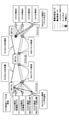
一例として、図2に示すように、ドメインAとドメインBとドメインCの3つのドメインが存在する場合について説明する。各ドメインにはNWコントローラ(図2中では「NW Ctrl」と表記)とSGLとが配備されている。図2中の「a1」~「a3」、「c1」~「c3」、「A1」、「B1」~「B2」及び「C1」はSLG IDを表す。なお、NWコントローラとはSLG等のNW機器の各種設定(転送テーブルを含む)を管理する機器、装置又はプログラム等のことである。
また、例えば、端末、サーバ/VM又はこれらが実行するアプリケーション処理等をスライス端点と表す。図2に示す例では、スライスA端点~スライスD端点の4つのスライス端点が存在し、それぞれの転送要件は「低遅延」、「広帯域」、「BE(ベストエフォート)・冗長化有」及び「BE・冗長化無」である。
更に、各SLG間のトンネルのトンネルIDは、「左側のSLGのSLG ID+右側のSLGのSLG ID-1~3」の形式で表されるものとし、末尾「1」は最優先転送パス、「2」は優先転送パス、「3」はBEパスを表すものとする。例えば、SLG ID「a1」のエッジSLGとSLG ID「A1」の中継SLGとの間には3つのトンネルが存在し、最優先転送パスであるトンネルのトンネルIDは「a1A1-1」、優先転送パスであるトンネルのトンネルIDは「a1A1-2」、BEパスであるトンネルのトンネルIDは「a1A1-3」と表される。
このとき、従来方式では、NWコントローラ間の連携により経路を学習して各SLGに転送テーブルを設定する経路学習処理と、各SLGに設定された転送テーブルによりパケットを転送する転送処理とが実行される。以下、経路学習処理の一例をS11~S13で説明し、転送処理の一例をS21~S23で説明する。
S11)各ドメインのNWコントローラは、自ドメインに配備されているエッジSLGのSLG IDを隣接ドメインのNWコントローラに通知する。図2に示す例では、ドメインCのNWコントローラがSLG ID「c1」~「c3」をドメインBのNWコントローラに通知する場合を示している。
S12)隣接ドメインのNWコントローラからSLG IDが通知された場合、各NWコントローラは、当該隣接ドメイン以外の隣接ドメインのNWコントローラに当該SLG IDを伝播する。図2に示す例では、ドメインBのNWコントローラがSLG ID「c1」~「c3」をドメインAのNWコントローラに伝播する場合を示している。
S13)また、隣接ドメインのNWコントローラからSLG IDが通知された場合、各NWコントローラは、当該SLG IDと通知元ドメインに基づいて、自ドメインに配備されているSLGに対して、当該SLG IDのエッジSLGにパケットを送信するための転送テーブルを設定する。すなわち、各NWコントローラは、当該SLG IDのエッジSLGにパケットを送信するための出力先トンネルのトンネルIDと、当該SLG IDと、転送優先度や冗長化有無等とを対応付けることで転送テーブルを設定する。図2に示す例では、ドメインAのNWコントローラが自ドメイン内のSLGに対して、SLG ID「c1」~「c3」のエッジSLGにパケットを送信するための転送テーブルを設定する場合を示している。
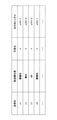
ここで、SLG ID「a1」のエッジSLGに設定されている転送テーブルの一例を図3に示す。図3に示すように、転送テーブルには、パケットの送信先のSLG IDと、転送優先度と、冗長化有無と、出力先トンネルのトンネルIDとが対応付けられている。なお、「*(アスタリスク)」はワイルドカードを表す。
これは、図3に示す転送テーブルでは、例えば、パケットの送信先のSLG IDが「c1」、転送優先度が「最優先」、冗長化が「*」である場合は、出力先トンネルが「a1A1-1」であることを表している。同様に、例えば、パケットの送信先のSLG IDが「c1」、転送優先度が「優先」、冗長化が「*」である場合は、出力先トンネルが「a1A1-2」であることを表している。なお、転送優先度や冗長化有無以外にも、転送テーブルには、例えば、NFの利用有無等が対応付けられることもある。
S21)各ドメインのエッジSLGは、スライス端点からパケットが入力された場合、当該パケットに対してスライス専用ヘッダを追加する。ここで、従来方式では、サービスの要件を満たすために必要なパケットの転送優先度や冗長要否等の転送要件(つまり、スライス要件)を示す情報と、対地となるエッジSLGのSLG IDと、スライスを一意に示す情報(以下、「スライスID」又は「スライス識別情報」という。)とをスライス専用ヘッダと定義する。
S22)各ドメインの各中継SLGは、他の中継SLGから転送されたパケットを受信すると、自身に設定されている転送テーブルを参照して、当該パケットのスライス専用ヘッダから適切な出力先トンネルを決定して当該パケットを転送する。
S23)そして、エッジSLGは、中継SLGから転送されたパケットを受信すると、当該パケットのスライス専用ヘッダに含まれるスライス識別情報を参照した後、当該スライス専用ヘッダを削除して適切なスライス端点(つまり、当該スライス識別情報に対応するスライス端点)に当該パケットを出力する。これにより、従来方式ではE2Eスライスが実現される。
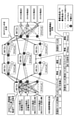
しかしながら、従来方式では、上述したように、ドメイン間が直線的に接続される単純なNW構成を想定している。このため、接続ドメイン数が増加してNW構成が面的に複雑化すると、各SLGに設定される転送テーブルが増大し、SLGの処理負荷の増大や転送性能の劣化等が発生し得る。例えば、図3に示すように、ドメインA~ドメインGの7つのドメインが存在する場合について説明する。なお、各記号や構成要素等の意味については図2と同様である。
このとき、上述したように、各SLGはエッジSLG毎に転送テーブルが設定されるため、接続ドメイン数の増加やSLG数の増加等のNW規模の増大に伴い、転送テーブルが増大する。このため、各SLGの負荷増大や転送性能の劣化等が発生し得る。
また、既存のドメイン内にエッジSLGが増設されたり、減設されたりすることで転送テーブルの更新が必要となる。接続ドメイン数が増加することで、この更新の頻度も高くなり、NWコントローラの負荷も増大する。例えば、ドメインGにSLG ID「g4」のエッジSLGが新設された場合(S31)、ドメインGのNWコントローラは隣接ドメイン(つまり、ドメインC、ドメインD及びドメインF)のNWコントローラに対してSLG ID「g4」を広告(通知)する(S32)。これにより、各ドメインのNWコントローラにSLG ID「g4」が伝播され(S33)、各ドメインの各SLGの転送テーブルがSLG ID「g4」と通知元ドメインに基づいて更新される(つまり、当該転送テーブルに対して、SLG ID「g4」のエッジSLGに対してパケットを送信するための情報が追加される。)。このように、エッジSLGの増設又は減設が発生する度に各NWコントローラは転送テーブルを更新するための経路学習処理を行う必要があり、その頻度はドメイン数の増加により増大するため、各NWコントローラの負荷が増大する。
更に、従来方式では、上述したように、各ドメインのNWコントローラ間でエッジSLGのSLG IDを交換することで経路学習を行っているが、同一エッジSLG宛ての経路が複数存在する場合は、経路毎の経由ドメイン数やパススペック(例えば、QoSクラスや冗長化有無等)、品質(例えば、帯域や遅延等)等の差異を考慮した最適経路を決定することができなかった。例えば、図4に示すように、ドメインAのエッジSLGからドメインGのエッジSLGへの経路は複数存在するが、経由ドメイン数、パススペック、品質等が異なる。すなわち、例えば、ドメインB及びドメインCを経由する経路と、ドメインDを経由する経路とでは経由ドメイン数が異なる。また、例えば、ドメインB及びドメインCを経由する経路と、ドメインE及びドメインFを経由する経路とでは経由ドメイン数は同じであるが、ドメインB及びドメインCを経由する経路は冗長化されており、様々な品質の経路をサポートしているのに対して、ドメインE及びドメインFを経由する経路はBE・経路冗長なしのみをサポートしており、そのパススペック及び品質が異なる。
このように、NW構成が面的に複雑化することで、従来方式では、(1)SLGの負荷増大や転送性能の低下が生じたり、NWコントローラの負荷増大が生じたりするといった課題と、(2)同一エッジSLG宛ての経路が複数存在する場合に経由ドメイン数やパススペック、品質等を考慮した最適経路を決定することができないといった課題とが発生する。
<本実施形態に係る経路学習処理及び転送処理>
そこで、本実施形態では、上記の(1)及び(2)の2つの課題を解決する経路学習処理及び転送処理について説明する。
そこで、本実施形態では、上記の(1)及び(2)の2つの課題を解決する経路学習処理及び転送処理について説明する。
≪転送処理≫
まず、経路学習処理が実行済であり、各SLGには転送テーブルが設定されているものとして、本実施形態に係る転送処理の一例を図5のS41~S44で説明する。なお、図5中の各記号や構成要素等の意味については図2と同様である。
まず、経路学習処理が実行済であり、各SLGには転送テーブルが設定されているものとして、本実施形態に係る転送処理の一例を図5のS41~S44で説明する。なお、図5中の各記号や構成要素等の意味については図2と同様である。
ここで、本実施形態に係る転送テーブルは、パケットの送信先としてSLG IDではなく、ドメインを一意に示す情報(以下、「ドメインID」という。)を対応付けたものである。一例として、SLG ID「a1」のエッジSLGに設定されている転送テーブルを図6に示す。図6に示すように、従来方式と異なり、本実施形態に係る転送テーブルでは、送信先として、SLG IDではなく、ドメインIDが用いられている。なお、冗長化における「1」及び「0」はそれぞれ冗長化有及び冗長化無を表す。
S41)各ドメインのエッジSLGは、スライス端点からパケットが入力された場合、当該パケットに対してスライス専用ヘッダを追加する。ここで、本実施形態では、サービスの要件を満たすために必要なパケットの転送優先度や冗長要否等の転送要件(つまり、スライス要件)を示す情報と、送信先ドメインのドメインIDと、スライス識別情報とをスライス専用ヘッダと定義する。すなわち、本実施形態に係るスライス専用ヘッダは、対地となるエッジSLGのSLG IDの代わりに、送信先ドメインのドメインIDを用いたものである。
S42)送信先ドメイン以外の各ドメインの各中継SLGは、他の中継SLGから転送されたパケットを受信すると、自身に設定されている転送テーブルを参照して、当該パケットのスライス専用ヘッダから適切な出力先トンネルを決定して当該パケットを転送する。
S43)送信先ドメインの各中継SLGは、他の中継SLGから転送されたパケットを受信すると、当該パケットのスライス専用ヘッダに含まれるスライス識別情報やその他の情報(例えば、当該パケットのヘッダに含まれる宛先IPアドレス等)に基づいて、自ドメイン内の該当のエッジSLGに当該パケットを転送する。
S44)そして、エッジSLGは、中継SLGから転送されたパケットを受信すると、当該パケットのスライス専用ヘッダに含まれるスライス識別情報を参照した後、当該スライス専用ヘッダを削除して適切なスライス端点(つまり、当該スライス識別情報に対応するスライス端点)に当該パケットを出力する。これにより、E2Eスライスが実現される。
このように、本実施形態に係る転送処理では、送信先としてSLG IDを指定するのではなく、より大きな単位であるドメインIDを指定したパケット転送を行う。このために、後述する経路学習処理では、送信先としてドメインIDを指定した転送テーブルを各SLGに設定する。これにより、各ドメイン内のエッジSLGを隠蔽することが可能となり、転送テーブルの増大が抑制され、SLGの負荷増大及び転送性能の劣化を抑止すると共に、エッジSLGの増設・減設に伴うNWコントローラの負荷増大を抑止することが可能となる。
≪経路学習処理≫
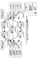
次に、本実施形態に係る経路学習処理の一例を図7のS51~S54で説明する。なお、図7中の各記号や構成要素等の意味については図2と同様である。
次に、本実施形態に係る経路学習処理の一例を図7のS51~S54で説明する。なお、図7中の各記号や構成要素等の意味については図2と同様である。
S51)各ドメインのNWコントローラは、自ドメインのドメインIDを到達先ドメインIDとして隣接ドメインのNWコントローラに広告(通知)する。図7に示す例では、ドメインGのNWコントローラがドメインID「G」を、ドメインCのNWコントローラとドメインDのNWコントローラとドメインFのNWコントローラとに広告する場合を示している。なお、到達先ドメインIDとはパケットの送信先となるドメインIDであることを意味している。
S52)隣接ドメインのNWコントローラから到達先ドメインIDが通知された場合、各NWコントローラは、当該隣接ドメイン以外の隣接ドメインのNWコントローラに経路情報を広告する。この経路情報には、当該到達先ドメインIDと、自ドメインのドメインIDを示す経由ドメインIDと、広告先ドメインに隣接する自ドメインの中継SLGと当該到達先ドメインIDの通知元ドメインの中継SLGとの間の区間の経路でサポートしているパススペック及びパススペック毎の品質情報(例えば、帯域及び遅延等)とが含まれる。図7に示す例では、到達先ドメインID「G」、経由ドメインID「F」、パススペック「BE・冗長化有り」、帯域「20Gbps」及び遅延「10msec」が経路情報に含まれている場合を示している。このパススペック、帯域及び遅延は、ドメインF内の中継SLGのうちドメインEに隣接する中継SLGと、ドメインG内の中継SLGのうちドメインFに隣接する中継SLGとの間の区間の経路でサポートされているパススペックと品質(帯域及び遅延)である。なお、或る経路でサポートしているパススペック及びパススペック毎の品質情報とは、当該経路で提供可能なパススペック及びこれらパススペック毎の品質の情報のことである。
S53)隣接ドメインのNWコントローラから経路情報が通知された場合、各NWコントローラは、当該経路情報をドメイン間接続テーブルに格納すると共に、経由ドメインIDに自ドメインのドメインIDを追加し、必要に応じてパススペック及び品質情報を更新した上で、当該隣接ドメイン以外の隣接ドメインのNWコントローラに経路情報を広告する。
このとき、パススペック及び品質情報の更新は以下のようにして行う。
(A)広告先ドメインに隣接する自ドメインの中継SLGと当該経路情報の通知元ドメインの中継SLGとの間の区間の経路でサポートしているパススペックの方が低い場合、この低い方のパススペックで経路情報を更新する。なお、パススペックが低いとは、当該区間でサポートされているパススペックの種類数が少ないこと、冗長化が無いことを意味する。
(B)該当のパススペックにおいて、当該区間の帯域の方が低い場合、この低い方の帯域で経路情報を更新する。
(C)該当のパススペックにおいて、当該区間の遅延を、経路情報に含まれる遅延に加算する。
上記の(A)~(C)について具体例を示すと、(A)では、例えば、通知された経路情報に含まれるパススペックが「最優先・冗長化有り」と「BE・冗長化有り」であり、広告先ドメインに隣接する自ドメインの中継SLGと当該経路情報の通知元ドメインの中継SLGとの間の区間の経路でサポートしているパススペックが「BE・冗長化有り」である場合、経路情報のパススペックは「BE・冗長化有り」に更新される(つまり、この場合、「最優先・冗長化有り」及びその品質情報(帯域、遅延)は経路情報から削除される。)。又は、例えば、通知された経路情報に含まれるパススペックが「最優先・冗長化有り」であり、広告先ドメインに隣接する自ドメインの中継SLGと当該経路情報の通知元ドメインの中継SLGとの間の区間の経路でサポートしているパススペックが「最優先・冗長化無し」である場合、経路情報のパススペックは「最優先・冗長化無し」に更新される。(B)では、例えば、通知された経路情報に含まれる或るパススペックの帯域が「20Gbps」であり、当該区間の当該パススペックの帯域が「10Gbps」である場合、経路情報に含まれる当該パススペックの帯域は「10Gbps」に更新される。(C)では、例えば、通知された経路情報に含まれる或るパススペックの遅延が「10msec」であり、当該区間の当該パススペックの遅延が「15msec」である場合、経路情報に含まれる当該パススペックの遅延は「25msec」に更新される。
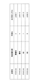
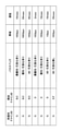
ここでドメインAのNWコントローラが保持しているドメイン間接続テーブルの一例を図8に示す。図8に示すように、本実施形態に係るドメイン間接続テーブルは、隣接ドメインのNWコントローラから通知された経路情報が格納されたテーブルである。このように、各NWコントローラは、到達先ドメインまでの経由ドメインやその到達先ドメインまでの経路のパススペック及び品質情報をドメイン間接続テーブルで管理している。これにより、経由ドメイン数やパススペック、品質情報を考慮した最適経路を選択するための転送テーブルを各SLGに設定することが可能となる。
S54)そして、各ドメインのNWコントローラは、自身が保持しているドメイン間接続テーブルに基づいて、自ドメイン内のSLGに対して、各ドメインIDにパケットを送信するための転送テーブルを設定する。このとき、各ドメインのNWコントローラは、到達先ドメインまでの経由ドメインやその到達先ドメインまでの経路のパススペック及び品質情報を考慮して、スライスが満たすべき転送要件に応じた経路情報を選択することで、当該経路情報に含まれる到達先ドメインIDを送信先ドメインID、パススペックを転送優先度、最初の経由ドメインIDにパケットを転送するためのトンネルを出力先トンネルとした転送テーブルを各SLGに設定する。これにより、各SLGに対して、経由ドメイン数やパススペック及び品質情報を考慮した最適経路でスライスを実現する転送テーブルが設定される。
なお、スライスが満たすべき転送要件に応じて、どのような経路情報を選択するかは様々に考えられ、ドメイン毎に様々な選択方法が採用され得る。以下に、図8に示すドメイン間接続テーブルを参照しながら、経路情報の選択方法の一例について説明する。
図7のスライスAは「低遅延スライス」である。このため、スライスAを利用するときに用いられる転送情報(転送テーブル内に1つのレコード)を設定する際には、例えば、図8に示すドメイン間接続テーブルに格納されている経路情報のうち、最も遅延が少ない経路情報(上から4行目の経路情報)を選択する。
図7のスライスBは「広帯域スライス」である。このため、スライスBを利用するときに用いられる転送情報を設定する際には、例えば、図8に示すドメイン間接続テーブルに格納されている経路情報のうち、最も帯域が大きい経路情報(上から2行目の経路情報)を選択する。
図7のスライスCは「BEスライス・冗長化有」である。このため、スライスCを利用するときに用いられる転送情報を設定する際には、例えば、図8に示すドメイン間接続テーブルに格納されている経路情報のうち、BEかつ冗長化有りで最も帯域が大きい経路情報(上から3行目の経路情報)を選択する。
図7のスライスDは「BEスライス・冗長化無」である。このため、スライスDを利用するときに用いられる転送情報を設定する際には、例えば、図8に示すドメイン間接続テーブルに格納されている経路情報のうち、BEかつ冗長化無しの経路情報(上から7行目の経路情報)を選択する。
なお、上記では経由ドメイン数は考慮しないで経路情報を選択する例を示したが、例えば、経路情報を選択する際に、パススペックや帯域の条件に加えて、できるだけ経由ドメイン数が少なくなるように経路情報を選択してもよい。
ここで、NW構成によっては、上記のS53で経路情報を広告する際に、NWコントローラ間の経路広告にループが発生する可能性がある。このため、ループの発生を防止するために、上記のS53では、各NWコントローラは、隣接ドメインへの広告対象となる経路情報と、当該隣接ドメインから自ドメインに広告された経路情報とを比較し、以下の条件を満たす場合には隣接ドメインに当該広告対象の経路情報を広告しないようにする。
条件:同一到達先ドメインかつ同一パススペックの経路情報において、隣接ドメインへの広告対象となる経路情報に含まれる経由ドメイン数(自ドメインも含む)が、当該隣接ドメインから広告された経路情報に含まれる経由ドメイン数以上である。
図9を用いて具体的に説明する。ドメインAのNWコントローラが保持しているドメイン間接続テーブルには、ドメインBのNWコントローラから通知された経路情報が既に格納されているものとする。このとき、ドメインDのNWコントローラから経路情報が通知された場合、ドメインAのNWコントローラは、ドメインBのNWコントローラには経路情報を通知(広告)しない。同一到達先ドメインかつ同一パススペックの経路情報において、ドメインDから広告された経路情報に基づきドメインAのNWコントローラで生成されたドメインBへの広告対象の経路情報に含まれる経由ドメイン数は2であり、ドメインBのNWコントローラから広告された経路情報に含まれる経由ドメイン数も2であり、上記の条件を満たすためである。
<機能構成>
次に、本実施形態に係るNWコントローラ10及びSLG(エッジSLG20及び中継SLG30)の機能構成について説明する。
次に、本実施形態に係るNWコントローラ10及びSLG(エッジSLG20及び中継SLG30)の機能構成について説明する。
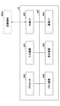
図10に示すように、本実施形態に係るNWコントローラ10は、品質管理部101と、経路計算部102とを有する。これらの各機能部は、プロセッサやメモリ装置等のハードウェアにより実現される。
品質管理部101は、自ドメイン内のエッジSLG20と中継SLG30間、中継SLG30と中継SLG30間、及び自ドメインの中継SLG30と隣接ドメインの中継SLG30間のパスのスペック(転送優先度や冗長化有無等)とパス毎の品質情報(利用可能な帯域や遅延等)を保持する。
経路計算部102は、自ドメインのドメインIDを到達先ドメインIDとして隣接ドメインに広告する。
また、経路計算部102は、隣接ドメインのNWコントローラ10から到達先ドメインIDが広告(通知)された場合、当該隣接ドメイン以外の隣接ドメインのNWコントローラ10に対して、当該到達先ドメインIDを含む経路情報を広告する。この際、経路計算部102は、自ドメインIDを経由ドメインIDとして当該経路情報に設定すると共に、品質管理部101で保持している情報に基づいて、広告先ドメインに隣接する自ドメイン内の中継SLG30と当該到達先ドメインIDの通知元ドメインの中継SLG30との間の区間の経路でサポートしているパススペック及びパススペック毎の品質情報(帯域や遅延等)を当該経路情報に設定する。
また、経路計算部102は、隣接ドメインのNWコントローラ10から経路情報が広告(通知)された場合、当該経路情報をドメイン間接続テーブルに格納すると共に、経由ドメインIDに自ドメインのドメインIDを追加し、品質管理部101で保持している情報に基づいて必要に応じてパススペック及び品質情報を更新した上で、当該隣接ドメイン以外の隣接ドメインのNWコントローラ10に経路情報を広告する。
また、経路計算部102は、ドメイン間接続テーブルを保持し、このドメイン間接続テーブルに格納されている経路情報に基づいて、自ドメイン内のエッジSLG20及び中継SLG30に対して転送テーブルを設定する。
図10に示すように、本実施形態に係るエッジSLG20は、ヘッダ設定部201と、転送処理部202とを有する。これらの各機能部は、プロセッサやメモリ装置等のハードウェアにより実現される。
ヘッダ設定部201は、スライス端点から入力されたパケットの5-tuple情報(送信元IPアドレス、送信先IPアドレス、送信元ポート番号、送信先ポート番号及びプロトコル番号)や入力I/F情報等に基づいて、当該パケットが所属するスライスを識別する。そして、ヘッダ設定部201は、その識別結果に基づいて、スライス要件と、送信先のドメインID、スライス識別情報とをスライス専用ヘッダとして当該パケットに付与する。なお、本実施形態では、ヘッダ設定部201がスライス専用ヘッダをパケットに付与する際には、スライス要件、送信先のドメインID、及びスライス識別情報は既知であるものとする。
また、ヘッダ設定部201は、中継SLG30から入力されたパケットに付与されているスライス専用ヘッダのスライス識別情報を参照した後、当該スライス専用ヘッダを削除した上で適切なスライス端点に当該パケットを出力する。
転送処理部202は、転送テーブルを保持し、この転送テーブルを参照して、パケットのスライス専用ヘッダに含まれる送信先ドメインID及び転送要件に合致する出力先トンネルを決定し、当該出力先トンネルにパケットを出力する。
図10に示すように、本実施形態に係る中継SLG30は、転送処理部301を有する。この機能部は、プロセッサやメモリ装置等のハードウェアにより実現される。
転送処理部301は、転送テーブルを保持し、この転送テーブルを参照して、パケットのスライス専用ヘッダに含まれる送信先ドメインID及び転送要件に合致する出力先トンネルを決定し、当該出力先トンネルにパケットを出力する。
また、転送処理部301は、パケットのスライス専用ヘッダに含まれる送信先ドメインIDが自ドメインIDである場合には、当該スライス専用ヘッダに含まれるスライス識別情報や当該パケットのヘッダに含まれる5-tuple情報等に基づいて、当該パケットが到達すべきエッジSLG20を特定する。そして、転送処理部301は、特定したエッジSLG20に対して、当該スライス専用ヘッダに含まれる転送要件を満たすパスを使用してパケットを出力する。なお、上記でエッジSLG20を特定するための条件は、例えばNWコントローラ10等によって設定され、本実施形態では既知であるものとする。
<実施例>
以下、上記の各機能部を用いて、経路学習処理のS51~S54と、転送処理のS41~S44とを説明する。
以下、上記の各機能部を用いて、経路学習処理のS51~S54と、転送処理のS41~S44とを説明する。
≪経路学習処理≫
S51)各ドメインのNWコントローラ10の経路計算部102は、自ドメインのドメインIDを到達先ドメインIDとして隣接ドメインのNWコントローラに広告(通知)する。
S51)各ドメインのNWコントローラ10の経路計算部102は、自ドメインのドメインIDを到達先ドメインIDとして隣接ドメインのNWコントローラに広告(通知)する。
S52)隣接ドメインのNWコントローラ10から到達先ドメインIDが通知された場合、各NWコントローラ10の経路計算部102は、当該隣接ドメイン以外の隣接ドメインのNWコントローラ10に経路情報を広告する。この経路情報には、当該到達先ドメインIDと、自ドメインのドメインIDを示す経由ドメインIDと、広告先ドメインに隣接する自ドメインの中継SLGと当該到達先ドメインIDの通知元ドメインの中継SLGとの間の区間の経路でサポートしているパススペック及びパススペック毎の品質情報(例えば、帯域及び遅延等)とが含まれる。このうち、パススペック及びパススペック毎の品質情報は、経路情報を広告するNWコントローラ10の品質管理部101で保持されている情報を利用する。
S53)隣接ドメインのNWコントローラ10から経路情報が通知された場合、各NWコントローラ10の経路計算部102は、当該経路情報をドメイン間接続テーブルに格納すると共に、経由ドメインIDに自ドメインのドメインIDを追加し、必要に応じてパススペック及び品質情報を更新した上で、当該隣接ドメイン以外の隣接ドメインのNWコントローラ10に経路情報を広告する。
このとき、パススペック及び品質情報の更新は、経路情報を広告するNWコントローラ10の品質管理部101で保持されているパススペック及び品質情報と、通知された経路情報に含まれるパススペック及び品質情報とを用いて、上記の(A)~(C)により更新する。
なお、上記のS53では、経路情報のループが発生しないように、経路計算部102は、上述した条件を満たす場合は隣接ドメインに経路情報を広告しないようにする。
S54)そして、各ドメインのNWコントローラ10の経路計算部102は、自身が保持しているドメイン間接続テーブルに基づいて、自ドメイン内のエッジSLG20及び中継SLG30に対して転送テーブルを設定する。
≪転送処理≫
S41)各ドメインのエッジSLG20のヘッダ設定部201は、スライス端点からパケットが入力された場合、当該パケットの5-tuple情報や入力I/F情報等に基づいて、当該パケットが所属するスライスを識別する。そして、ヘッダ設定部201は、その識別結果に基づいて、当該パケットに対してスライス専用ヘッダを追加(付与)する。
S41)各ドメインのエッジSLG20のヘッダ設定部201は、スライス端点からパケットが入力された場合、当該パケットの5-tuple情報や入力I/F情報等に基づいて、当該パケットが所属するスライスを識別する。そして、ヘッダ設定部201は、その識別結果に基づいて、当該パケットに対してスライス専用ヘッダを追加(付与)する。
S42)送信先ドメイン以外の各ドメインの各中継SLG30の転送処理部301は、他の中継SLG30から転送されたパケットを受信すると、自身に設定されている転送テーブルを参照して、当該パケットのスライス専用ヘッダから適切な出力先トンネルを決定して当該パケットを転送する。
S43)送信先ドメインの各中継SLG30の転送処理部301は、他の中継SLG30から転送されたパケットを受信すると、当該パケットのスライス専用ヘッダに含まれるスライス識別情報や当該パケットのヘッダに含まれる5-tuple情報等に基づいて、自ドメイン内の該当のエッジSLG20に当該パケットを転送する。
S44)そして、エッジSLG20の転送処理部202は、中継SLG30から転送されたパケットを受信すると、当該パケットのスライス専用ヘッダに含まれるスライス識別情報を参照した後、当該スライス専用ヘッダを削除して適切なスライス端点に当該パケットを出力する。
<ハードウェア構成>
最後に、本実施形態に係るNWコントローラ10、エッジSLG20及び中継SLG30のハードウェア構成について説明する。
最後に、本実施形態に係るNWコントローラ10、エッジSLG20及び中継SLG30のハードウェア構成について説明する。
≪NWコントローラ10≫
図11に示すように、本実施形態に係るNWコントローラ10は、入力装置401と、表示装置402と、外部I/F403と、通信I/F404と、プロセッサ405と、メモリ装置406とを有する。これら各ハードウェアは、それぞれがバス407を介して通信可能に接続されている。
図11に示すように、本実施形態に係るNWコントローラ10は、入力装置401と、表示装置402と、外部I/F403と、通信I/F404と、プロセッサ405と、メモリ装置406とを有する。これら各ハードウェアは、それぞれがバス407を介して通信可能に接続されている。
入力装置401は、例えば、キーボードやマウス、タッチパネル等である。表示装置402は、例えば、ディスプレイ等である。なお、NWコントローラ10は、入力装置401及び表示装置402のうちの少なくとも一方を有していなくてもよい。
外部I/F403は、例えば、記録媒体403a等の外部装置とのインタフェースである。なお、記録媒体403aには、例えば、CD(Compact Disc)、DVD(Digital Versatile Disc)、SDメモリカード(Secure Digital memory card)、USB(Universal Serial Bus)メモリカード等がある。
通信I/F404は、通信ネットワークに接続するためのインタフェースである。プロセッサ405は、例えば、CPU(Central Processing Unit)等の演算装置である。メモリ装置406は、例えば、HDD(Hard Disk Drive)やSSD(Solid State Drive)、RAM(Random Access Memory)、ROM(Read Only Memory)、フラッシュメモリ等の各種記憶装置である。
本実施形態に係るNWコントローラ10は、図11に示すハードウェア構成を有することにより、上述した各種処理を実現することができる。なお、図11に示すハードウェア構成は一例であって、NWコントローラ10は、他のハードウェア構成を有していてもよい。例えば、NWコントローラ10は、複数のプロセッサ405を有していてもよいし、複数のメモリ装置406を有していてもよい。
≪エッジSLG20及び中継SLG30≫
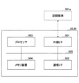
図12に示すように、本実施形態に係るエッジSLG20及び中継SLG30は、外部I/F501と、通信I/F502と、プロセッサ503と、メモリ装置504とを有する。これら各ハードウェアは、それぞれがバス505を介して通信可能に接続されている。
図12に示すように、本実施形態に係るエッジSLG20及び中継SLG30は、外部I/F501と、通信I/F502と、プロセッサ503と、メモリ装置504とを有する。これら各ハードウェアは、それぞれがバス505を介して通信可能に接続されている。
外部I/F501は、例えば、記録媒体501a等の外部装置とのインタフェースである。なお、記録媒体501aには、例えば、microSDやUSBメモリカード等がある。
通信I/F502は、通信ネットワークに接続するためのインタフェースである。プロセッサ503は、例えば、CPU等の演算装置である。メモリ装置504は、例えば、フラッシュメモリ、RAM、ROM等の各種記憶装置である。
本実施形態に係るエッジSLG20及び中継SLG30は、図12に示すハードウェア構成を有することにより、上述した各種処理を実現することができる。なお、図12に示すハードウェア構成は一例であって、エッジSLG20及び中継SLG30は、他のハードウェア構成を有していてもよい。例えば、エッジSLG20及び中継SLG30は、複数のプロセッサ503を有していてもよいし、複数のメモリ装置504を有していてもよい。
本発明は、具体的に開示された上記の実施形態に限定されるものではなく、請求の範囲の記載から逸脱することなく、種々の変形や変更、既知の技術との組み合わせ等が可能である。
10 NWコントローラ
20 エッジSLG
30 中継SLG
101 品質管理部
102 経路計算部
201 ヘッダ設定部
202 転送処理部
301 転送処理部
401 入力装置
402 表示装置
403 外部I/F
403a 記録媒体
404 通信I/F
405 プロセッサ
406 メモリ装置
407 バス
501 外部I/F
501a 記録媒体
502 通信I/F
503 プロセッサ
504 メモリ装置
505 バス
20 エッジSLG
30 中継SLG
101 品質管理部
102 経路計算部
201 ヘッダ設定部
202 転送処理部
301 転送処理部
401 入力装置
402 表示装置
403 外部I/F
403a 記録媒体
404 通信I/F
405 プロセッサ
406 メモリ装置
407 バス
501 外部I/F
501a 記録媒体
502 通信I/F
503 プロセッサ
504 メモリ装置
505 バス
Claims (8)
- パケットの転送要件を示すスライス要件と、前記パケットの送信先のドメインを示す送信先ドメインIDとが含まれるヘッダが付与されたパケットを受信すると、前記パケットの転送先のトンネルを決定するための転送テーブルを参照して、前記スライス要件及び前記送信先ドメインIDに対応するトンネルを特定する転送先特定部と、
前記転送先特定部により特定されたトンネルに対して、前記パケットを出力する転送部と、
を有することを特徴とするゲートウェイ装置。 - 前記ヘッダには、前記スライスを識別するための識別情報が更に含まれ、
前記転送先特定部は、
前記送信先ドメインIDが、自身が属するドメインのドメインIDでない場合は、前記転送テーブルを参照して、前記スライス要件及び前記送信先ドメインIDに対応するトンネルを特定し、
前記送信先ドメインIDが、自身が属するドメインのドメインIDである場合は、前記識別情報と前記パケットの5-tuple情報との少なくとも一方に基づいて、自身が属するドメイン内のエッジに配備されている他のゲートウェイ装置を特定し、特定した他のゲートウェイ装置に対して前記パケットを転送するためのトンネルであって、かつ、前記スライス要件を満たすトンネルを特定する、ことを特徴とする請求項1に記載のゲートウェイ装置。 - 所定の区間の間の経路の経路種別と、前記経路種別毎の品質情報とを管理する管理部と、
通信ネットワークを介して接続される他のネットワーク制御装置との間で、E2Eの経路の送信先ドメインIDと経由ドメインIDと前記経路の経路種別と前記経路の品質情報とを含む経路情報を交換する経路交換部と、
前記経路交換部で交換した経路情報を用いて、自ドメイン内のゲートウェイ装置に対して、前記送信先ドメインIDのドメインにパケットを送信するための転送テーブルを設定する設定部と、
を有することを特徴とするネットワーク制御装置。 - 前記経路交換部は、
前記管理部で管理されている経路種別及び前記経路種別毎の品質情報と、前記経路情報に含まれる経路種別及び前記経路種別毎の品質情報とを比較し、所定の条件を満たす場合は前記経路情報を更新した上で、更新後の経路情報を他のネットワーク制御装置に送信することで経路情報を交換する、ことを特徴とする請求項3に記載のネットワーク制御装置。 - パケットの転送要件を示すスライス要件と、前記パケットの送信先のドメインを示す送信先ドメインIDとが含まれるヘッダが付与されたパケットを受信すると、前記パケットの転送先のトンネルを決定するための転送テーブルを参照して、前記スライス要件及び前記送信先ドメインIDに対応するトンネルを特定する転送先特定手順と、
前記転送先特定手順で特定されたトンネルに対して、前記パケットを出力する転送手順と、
をコンピュータが実行することを特徴とする方法。 - 所定の区間の間の経路の経路種別と、前記経路種別毎の品質情報とを管理する管理部を有するコンピュータが、
通信ネットワークを介して接続される他のネットワーク制御装置との間で、E2Eの経路の送信先ドメインIDと経由ドメインIDと前記経路の経路種別と前記経路の品質情報とを含む経路情報を交換する経路交換手順と、
前記経路交換手順で交換した経路情報を用いて、自ドメイン内のゲートウェイ装置に対して、前記送信先ドメインIDのドメインにパケットを送信するための転送テーブルを設定する設定手順と、
を実行することを特徴とする方法。 - コンピュータを、請求項1又は2に記載のゲートウェイ装置、又は、請求項3又は4に記載のネットワーク制御装置、として機能させるプログラム。
- パケット転送を行うゲートウェイ装置と、前記パケット転送に用いられる転送テーブルを前記ゲートウェイ装置に設定するネットワーク制御装置とが含まれるシステムであって、
前記ネットワーク制御装置は、
所定の区間の間の経路の経路種別と、前記経路種別毎の品質情報とを管理する管理部と、
通信ネットワークを介して接続される他のネットワーク制御装置との間で、E2Eの経路の送信先ドメインIDと経由ドメインIDと前記経路の経路種別と前記経路の品質情報とを含む経路情報を交換する経路交換部と、
前記経路交換部で交換した経路情報を用いて、自ドメイン内のゲートウェイ装置に対して、前記送信先ドメインIDのドメインにパケットを送信するための転送テーブルを設定する設定部と、を有し、
前記ゲートウェイ装置は、
パケットの転送要件を示すスライス要件と、前記パケットの送信先のドメインを示す送信先ドメインIDとが含まれるヘッダが付与されたパケットを受信すると、前記パケットの転送先のトンネルを決定するための転送テーブルを参照して、前記スライス要件及び前記送信先ドメインIDに対応するトンネルを特定する転送先特定部と、
前記転送先特定部により特定されたトンネルに対して、前記パケットを出力する転送部と、を有することを特徴とするシステム。
Priority Applications (3)
| Application Number | Priority Date | Filing Date | Title |
|---|---|---|---|
| JP2022545178A JP7396504B2 (ja) | 2020-08-27 | 2020-08-27 | ゲートウェイ装置、ネットワーク制御装置、方法、プログラム及びシステム |
| US18/042,879 US20230319698A1 (en) | 2020-08-27 | 2020-08-27 | Gateway apparatus, network control apparatus, method, program and system |
| PCT/JP2020/032484 WO2022044232A1 (ja) | 2020-08-27 | 2020-08-27 | ゲートウェイ装置、ネットワーク制御装置、方法、プログラム及びシステム |
Applications Claiming Priority (1)
| Application Number | Priority Date | Filing Date | Title |
|---|---|---|---|
| PCT/JP2020/032484 WO2022044232A1 (ja) | 2020-08-27 | 2020-08-27 | ゲートウェイ装置、ネットワーク制御装置、方法、プログラム及びシステム |
Publications (1)
| Publication Number | Publication Date |
|---|---|
| WO2022044232A1 true WO2022044232A1 (ja) | 2022-03-03 |
Family
ID=80352910
Family Applications (1)
| Application Number | Title | Priority Date | Filing Date |
|---|---|---|---|
| PCT/JP2020/032484 Ceased WO2022044232A1 (ja) | 2020-08-27 | 2020-08-27 | ゲートウェイ装置、ネットワーク制御装置、方法、プログラム及びシステム |
Country Status (3)
| Country | Link |
|---|---|
| US (1) | US20230319698A1 (ja) |
| JP (1) | JP7396504B2 (ja) |
| WO (1) | WO2022044232A1 (ja) |
Cited By (1)
| Publication number | Priority date | Publication date | Assignee | Title |
|---|---|---|---|---|
| JPWO2024042589A1 (ja) * | 2022-08-22 | 2024-02-29 |
Citations (4)
| Publication number | Priority date | Publication date | Assignee | Title |
|---|---|---|---|---|
| JP2017175522A (ja) * | 2016-03-25 | 2017-09-28 | 日本電気株式会社 | ネットワークシステム、制御装置、方法およびプログラム |
| US20170289020A1 (en) * | 2016-04-01 | 2017-10-05 | Futurewei Technologies, Inc. | PCEP Extension for PCECC Support of Distributed Computing, Multiple Services, and Inter-Domain Routing |
| US20180041424A1 (en) * | 2016-08-05 | 2018-02-08 | Huawei Technologies Co., Ltd. | Slice/service-based routing in virtual networks |
| JP2020028060A (ja) * | 2018-08-14 | 2020-02-20 | 日本電信電話株式会社 | 通信システム及び通信方法 |
Family Cites Families (4)
| Publication number | Priority date | Publication date | Assignee | Title |
|---|---|---|---|---|
| US6961573B1 (en) * | 2000-12-22 | 2005-11-01 | Cisco Technology, Inc. | System and method for routing communications based on wireless communication link quality |
| EP3029961A1 (en) * | 2014-12-01 | 2016-06-08 | Alcatel Lucent | Method and device for a connectionless bearer service |
| US11070395B2 (en) | 2015-12-09 | 2021-07-20 | Nokia Of America Corporation | Customer premises LAN expansion |
| CN112910792B (zh) | 2018-08-30 | 2023-06-20 | 华为技术有限公司 | 报文处理的方法、装置及相关设备 |
-
2020
- 2020-08-27 US US18/042,879 patent/US20230319698A1/en active Pending
- 2020-08-27 JP JP2022545178A patent/JP7396504B2/ja active Active
- 2020-08-27 WO PCT/JP2020/032484 patent/WO2022044232A1/ja not_active Ceased
Patent Citations (4)
| Publication number | Priority date | Publication date | Assignee | Title |
|---|---|---|---|---|
| JP2017175522A (ja) * | 2016-03-25 | 2017-09-28 | 日本電気株式会社 | ネットワークシステム、制御装置、方法およびプログラム |
| US20170289020A1 (en) * | 2016-04-01 | 2017-10-05 | Futurewei Technologies, Inc. | PCEP Extension for PCECC Support of Distributed Computing, Multiple Services, and Inter-Domain Routing |
| US20180041424A1 (en) * | 2016-08-05 | 2018-02-08 | Huawei Technologies Co., Ltd. | Slice/service-based routing in virtual networks |
| JP2020028060A (ja) * | 2018-08-14 | 2020-02-20 | 日本電信電話株式会社 | 通信システム及び通信方法 |
Cited By (3)
| Publication number | Priority date | Publication date | Assignee | Title |
|---|---|---|---|---|
| JPWO2024042589A1 (ja) * | 2022-08-22 | 2024-02-29 | ||
| WO2024042589A1 (ja) * | 2022-08-22 | 2024-02-29 | 日本電信電話株式会社 | コンフィグ投入装置、コンフィグ投入方法、及びコンフィグ投入プログラム |
| JP7810274B2 (ja) | 2022-08-22 | 2026-02-03 | Ntt株式会社 | コンフィグ投入装置、コンフィグ投入方法、及びコンフィグ投入プログラム |
Also Published As
| Publication number | Publication date |
|---|---|
| JPWO2022044232A1 (ja) | 2022-03-03 |
| US20230319698A1 (en) | 2023-10-05 |
| JP7396504B2 (ja) | 2023-12-12 |
Similar Documents
| Publication | Publication Date | Title |
|---|---|---|
| JP4416733B2 (ja) | 状態の同期化を有するクラスタのための仮想マルチキャスト経路指定 | |
| CN113472646B (zh) | 一种数据传输方法、节点、网络管理器及系统 | |
| US9743367B2 (en) | Link layer discovery protocol (LLDP) on multiple nodes of a distributed fabric | |
| US12261767B2 (en) | Best path computation offload in a network computing environment | |
| WO2021135468A1 (zh) | 段标识的确定方法和设备 | |
| WO2014118938A1 (ja) | 通信経路の管理方法 | |
| WO2020135395A1 (zh) | 一种跨内部网关协议的前缀标识通告方法和装置 | |
| US9628410B2 (en) | Switch and switch system for enabling paths between domains | |
| JP7388533B2 (ja) | ゲートウェイ装置、方法及びプログラム | |
| EP2962411A1 (en) | System and method for traffic polarization during failures | |
| US20230041526A1 (en) | Centralized path computation for information-centric networking | |
| US20260005955A1 (en) | Method and apparatus for handling link failure, and storage medium | |
| US20140317271A1 (en) | Method and node apparatus for collecting information in content network based on information-centric networking | |
| JP7396504B2 (ja) | ゲートウェイ装置、ネットワーク制御装置、方法、プログラム及びシステム | |
| CN113595915A (zh) | 转发报文的方法及相关设备 | |
| WO2020181733A1 (zh) | 一种基于vpc的多数据中心互通方法及相关设备 | |
| JP5105327B2 (ja) | オーバレイノード、該オーバレイノードを備えたオーバレイネットワークおよびオーバレイルーティング方法とそのためのプログラム | |
| CN114301839A (zh) | 一种组播报文传输方法及装置 | |
| US20200028711A1 (en) | Heterogeneous capabilities in an overlay fabric | |
| JP4743640B2 (ja) | オーバーレイネットワーク形成方法とオーバーレイノードおよびオーバーレイネットワークとプログラム | |
| CN113904973B (zh) | 路由更新方法、介质、装置和计算设备 | |
| US11916699B1 (en) | Backbone network traffic efficiency analysis | |
| CN112751766A (zh) | 报文转发方法、装置及计算机存储介质 | |
| JP2016046697A (ja) | 経路制御システムおよびその方法 | |
| JP7332869B2 (ja) | 通信プログラム、通信方法および通信装置 |
Legal Events
| Date | Code | Title | Description |
|---|---|---|---|
| ENP | Entry into the national phase |
Ref document number: 2022545178 Country of ref document: JP Kind code of ref document: A |
|
| NENP | Non-entry into the national phase |
Ref country code: DE |
|
| 122 | Ep: pct application non-entry in european phase |
Ref document number: 20951484 Country of ref document: EP Kind code of ref document: A1 |