WO2022044136A1 - 無線通信システム連携方法および無線通信システム制御装置 - Google Patents
無線通信システム連携方法および無線通信システム制御装置 Download PDFInfo
- Publication number
- WO2022044136A1 WO2022044136A1 PCT/JP2020/032078 JP2020032078W WO2022044136A1 WO 2022044136 A1 WO2022044136 A1 WO 2022044136A1 JP 2020032078 W JP2020032078 W JP 2020032078W WO 2022044136 A1 WO2022044136 A1 WO 2022044136A1
- Authority
- WO
- WIPO (PCT)
- Prior art keywords
- wireless
- wireless lan
- communication
- wireless terminal
- mobile communication
- Prior art date
- Legal status (The legal status is an assumption and is not a legal conclusion. Google has not performed a legal analysis and makes no representation as to the accuracy of the status listed.)
- Ceased
Links
Images





Classifications
-
- H—ELECTRICITY
- H04—ELECTRIC COMMUNICATION TECHNIQUE
- H04W—WIRELESS COMMUNICATION NETWORKS
- H04W36/00—Hand-off or reselection arrangements
- H04W36/0005—Control or signalling for completing the hand-off
- H04W36/0011—Control or signalling for completing the hand-off for data sessions of end-to-end connection
- H04W36/0022—Control or signalling for completing the hand-off for data sessions of end-to-end connection for transferring data sessions between adjacent core network technologies
- H04W36/00222—Control or signalling for completing the hand-off for data sessions of end-to-end connection for transferring data sessions between adjacent core network technologies between different packet switched [PS] network technologies, e.g. transferring data sessions between LTE and WLAN or LTE and 5G
-
- H—ELECTRICITY
- H04—ELECTRIC COMMUNICATION TECHNIQUE
- H04W—WIRELESS COMMUNICATION NETWORKS
- H04W36/00—Hand-off or reselection arrangements
- H04W36/0005—Control or signalling for completing the hand-off
- H04W36/0055—Transmission or use of information for re-establishing the radio link
- H04W36/0066—Transmission or use of information for re-establishing the radio link of control information between different types of networks in order to establish a new radio link in the target network
-
- H—ELECTRICITY
- H04—ELECTRIC COMMUNICATION TECHNIQUE
- H04W—WIRELESS COMMUNICATION NETWORKS
- H04W36/00—Hand-off or reselection arrangements
- H04W36/14—Reselecting a network or an air interface
- H04W36/144—Reselecting a network or an air interface over a different radio air interface technology
- H04W36/1443—Reselecting a network or an air interface over a different radio air interface technology between licensed networks
-
- H—ELECTRICITY
- H04—ELECTRIC COMMUNICATION TECHNIQUE
- H04W—WIRELESS COMMUNICATION NETWORKS
- H04W36/00—Hand-off or reselection arrangements
- H04W36/14—Reselecting a network or an air interface
- H04W36/144—Reselecting a network or an air interface over a different radio air interface technology
- H04W36/1446—Reselecting a network or an air interface over a different radio air interface technology wherein at least one of the networks is unlicensed
-
- H—ELECTRICITY
- H04—ELECTRIC COMMUNICATION TECHNIQUE
- H04W—WIRELESS COMMUNICATION NETWORKS
- H04W72/00—Local resource management
- H04W72/04—Wireless resource allocation
-
- H—ELECTRICITY
- H04—ELECTRIC COMMUNICATION TECHNIQUE
- H04W—WIRELESS COMMUNICATION NETWORKS
- H04W72/00—Local resource management
- H04W72/50—Allocation or scheduling criteria for wireless resources
- H04W72/54—Allocation or scheduling criteria for wireless resources based on quality criteria
-
- H—ELECTRICITY
- H04—ELECTRIC COMMUNICATION TECHNIQUE
- H04W—WIRELESS COMMUNICATION NETWORKS
- H04W72/00—Local resource management
- H04W72/50—Allocation or scheduling criteria for wireless resources
- H04W72/56—Allocation or scheduling criteria for wireless resources based on priority criteria
Definitions
- This disclosure relates to a wireless communication system cooperation method and a wireless communication system control device, and more particularly to a wireless communication system cooperation method and a wireless communication system control device suitable for cooperation between a mobile communication system with priority control and a wireless LAN system. ..
- 5G 5th generation
- L5G local 5G services
- 5G includes “L5G” without distinguishing between the two.
- 5G communication services can provide high-quality wireless access, but the introduction and maintenance of the communication system requires a large amount of cost. Therefore, it is not always easy to cover the entire desired service area with a 5G communication system.
- Non-Patent Document 2 discloses details about IEEE 802.11ax called WiFi6.
- CSMA / CA Carrier Sense Multiple Access / Collision Avoidance
- the terminals connected to the wireless LAN access point (AP) perform carrier sense and communicate when the availability of the wireless channel can be confirmed.
- the communication time allocated to each terminal decreases, and a situation may occur in which the desired communication quality cannot be maintained. For this reason, it is difficult to continuously provide high-quality communication by simply supplementing the out-of-service area of mobile communication with a conventional wireless LAN.
- the first object is to provide a wireless communication system cooperation method that can be made to operate. Further, this disclosure provides a control device for a wireless communication system capable of maintaining desired communication quality even in a communication section by wireless LAN by satisfactorily linking mobile communication with priority control and wireless LAN. That is the second purpose.
- the first aspect is a wireless communication system cooperation method for achieving the above object, which is a mobile communication in which a service data flow is exchanged between a data network and a wireless terminal via a mobile communication base station.
- a step a step of detecting the transfer of the wireless terminal from the mobile communication to the wireless LAN and vice versa, and a step of detecting the wireless terminal to the wireless LAN and then receiving the mobile communication.
- the mobile communication step comprises a wireless LAN communication step that transfers the service data flow between the data network and the wireless terminal via the wireless LAN access point until it is passed, and the mobile communication step represents communication quality.
- the service data flow is communicated between the data network and the wireless terminal via the base station so that the step of assigning the indicator to the service data flow and the communication quality corresponding to the indicator are realized.
- the wireless LAN communication step includes a priority control setting step for setting a wireless LAN frequency resource to be allocated to the wireless terminal passed to the wireless LAN based on the indicator, and the wireless terminal.
- the second aspect is a mobile communication system that exchanges service data flows between a data network and a wireless terminal via a base station for mobile communication, and the data network via a wireless LAN access point.
- a wireless communication system control device that controls cooperation with a wireless LAN communication system that exchanges service data flows with and from the wireless terminal, and is capable of communicating with the mobile communication core network and the access point.
- the information collection unit that collects information about the indicator assigned to the flow via the communication interface unit and the frequency resource of the wireless LAN to be assigned to the wireless terminal passed to the wireless LAN are set based on the indicator.
- the access point is instructed to set by the wireless LAN priority control setting unit, and the wireless terminal is used for the mobile communication. It is desirable to have a wireless LAN priority control instruction unit that releases the setting when it is handed over.
- the communication resource of the wireless LAN responsible for the communication between the data network and the wireless terminal is set based on the indicator. Therefore, according to the aspect of the present disclosure, it is possible to stably maintain the communication quality comparable to that of the mobile communication even by the wireless LAN.
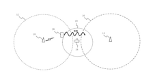
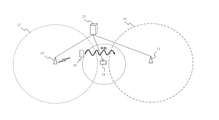
- FIG. 1 shows an example of an area covered by a mobile communication system and a wireless LAN communication system.
- This mobile communication system shall be a 5G communication service compliant with the 5th generation standard.
- the example shown in FIG. 1 includes a first base station 10.
- the first base station 10 has a radio wave reachable range 12.
- the example shown in FIG. 1 further includes a second base station 14 compliant with 5G.
- the second base station 14 has a radio wave reachable range 16.
- the radio wave reachable range 12 of the first base station 10 and the radio wave reachable range 16 of the second base station 14 do not overlap, and there is a 5G out-of-range area between the two.
- the wireless LAN access point AP18 is installed so as to cover the area outside the service area.
- AP18 shall comply with the IEEE 802.11ax standard, that is, the so-called WiFi 6 standard.
- the example shown in FIG. 1 shows how the wireless terminal 20 moves from the radio wave reachable range 12 of the first base station 10 to the radio wave reachable range 16 of the second base station 14 via the communication area 19 of the AP18.
- the wireless terminal 20 can perform 5G-compliant communication while belonging to the radio wave reachable range 12 and after entering the radio wave reachable range 16. Then, in order to continuously obtain good communication quality during the above movement, it is important to maintain communication quality comparable to 5G between the wireless terminal 20 and AP18.
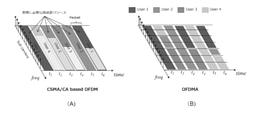
- Figure 2 (A) shows the wireless LAN communication method used in IEEE802.ac, which is a standard before WiFi6.
- 1 to 4 users belonging to the communication area of the wireless LAN carry out carrier sense, respectively, and perform communication in a time-divided manner so that mutual communication does not collide.
- each of the users 1 to 4 communicates using a desired number of subcarriers among a plurality of subcarriers separated by a predetermined frequency width.
- the frequency resources actually required for each time slot may be part of the whole as shown.
- FIG. 2B shows the communication method used in WiFi6.
- WiFi6 available subcarriers are assigned to multiple users for each time slot. In this case, as shown, the entire available frequency resource is effectively utilized in each time slot. Therefore, according to the method of WiFi6, it is easy to maintain high communication quality in a situation where a large number of users exist as compared with the method before that.
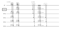
- FIG. 3 shows an example of a timing chart when five wireless terminals STA1 to STA5 communicate with an AP compliant with WiFi6 in uplink (UL) and downlink (DL) by the OFDMA method. Further, here, it is assumed that STA1 is a wireless terminal that is protected such as a bit rate guaranteed type in 5G communication.
- the display of "DL-OFDMA" shown in the upper left of FIG. 3 means downlink communication by the OFDMA method.
- the display of "DL-MU” means downlink-multi-user communication in which data is simultaneously transmitted to a plurality of wireless terminals in the same time slot. If there are four available resource units (RU), RU1 to RU4, data cannot be transmitted to all five terminals STA1 to STA5 at the same time. Therefore, if the RU allocation is randomly determined, as shown in the figure, the RU is not assigned to the protected terminal STA1, and a situation may occur in which the desired communication cannot be executed in the STA1.
- the display of "UL-OFDMA” shown in the upper center of FIG. 3 means uplink communication by the OFDMA method.
- the display of "UL-MU” means uplink-multi-user communication.
- TR-R trigger frame
- the wireless terminals STA1 to STA5 use different RUs to send data to the AP all at once.
- the RU used by STA1 and the RU used by another wireless terminal (STA2) may overlap. Then, in that case, the data of STA1 and the data of STA2 collide with each other, and a situation occurs in which desired communication cannot be executed in STA1.
- the AP that received the uplink data returns an acknowledgment signal (BA: Block Acknowledge) to all the wireless terminals that are the source of the received data.
- BA Block Acknowledge
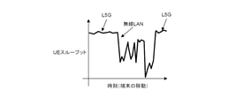
- FIG. 4 shows a state in which the throughput in the communication area of the wireless LAN is significantly deteriorated when the wireless terminal STA1 moves by the route shown in FIG.
- the communication quality of STA1 which is the protection target, is not as good as the communication between the 5G communication system and the wireless LAN communication system. , May be significantly degraded in the wireless LAN communication area.
- FIG. 5 shows an overall view of the communication system according to the first embodiment of the present disclosure.
- the same elements as those shown in FIG. 1 are designated by the same reference numerals, and the description thereof will be omitted or simplified.
- the communication system of this embodiment includes a control device 22.
- the control device 22 can exchange information and commands between the first base station 10, the second base station 14, and the AP18, respectively.
- FIG. 6 is a block diagram functionally representing the communication system shown in FIG. As shown in FIG. 6, the control device 22 is connected to the 5G core network (5GC) 24.
- a 5G base station gNB constituting a 5G access network is connected to the 5GC24.
- the base station gNB corresponds to the first base station 10 and the second base station 14 in FIG. 1 or FIG.
- the 5GC24 is further connected to the N3IWF (non-3GPP Inter-Working Function) 26.
- N3IWF is a device for supporting connection to 5G via a non-3GPP access network such as wireless LAN.
- AP18 is connected to N3IWF26. Then, the wireless terminal 20 belonging to the communication area of AP18 can obtain a connection with 5GC via AP18 and N3IWF.
- FIG. 7 shows an outline of QoS (Quality of Service) control in 5G.
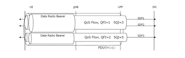
- FIG. 7 shows a state in which three service data flows SDF1 to SDF3 are established between one wireless terminal (UE) and a data network (DN) in 5G communication.
- SDF1 to SDF3 are, for example, data flows used in different applications.
- a QoS flow can be set for each SDF. Then, each identifier QFI (QoS Flow Identifier) is assigned to the QoS flow.
- the QFI allocation is determined based on the priority control policy in the UPF (User Plane Function), which is a part of the 5GC24, or the wireless terminal UE.
- UPF User Plane Function
- FIG. 7 there is a wired section between the base station gNB and UPF.
- the value of 5QI which is a QoS indicator defined by 5G
- the wireless section between the wireless terminal UE and the base station gNB.
- a data radio bearer (Date Radio Bearer: DRB) is assigned to each QoS flow, and 5QI is mapped to that DRB.
- DRB Data Radio Bearer
- These mappings are performed in the UPF for downlink (DL) flows.
- the UPR (UL) flow is mapped by the UE. Mapping in UE is done by setting QFI of DL to UL of the same flow.
- FIG. 8 is a list showing the combination of the 5QI value and the corresponding QoS characteristic.
- the 5QI value determines, for example, whether the resource type is bitrate guaranteed (GBR), bitrate non-guaranteed (Non-GBR), or delayed critical GBR. ..
- the 5QI value also defines the priority level, packet delay budget, packet error rate, maximum data burst amount, averaging window and service example.
- each SDF is communicated so that the QoS characteristics defined by 5QI are satisfied.
- FIG. 9 is a diagram for explaining an outline of priority control performed after the wireless terminal 20 is handed over from the 5G to the wireless LAN in the present embodiment.
- the QFI and 5QI information assigned by 5G is also used in the wireless LAN.
- This embodiment is characterized in that priority control is performed based on the QFI in the wireless LAN network section between the UE and the N3IWF.
- priority control is realized by allocating the OFDMA resource unit RU fixedly according to 5QI in this section.
- RUs are fixedly assigned according to the 5QI with the highest priority.
- FIG. 9 there is a wired section between AP and N3IWF.
- priority control is realized by making the band reservation ratio fixedly correspond to 5QI in this section.
- the bandwidth allocation ratio is set based on the highest priority 5QI.
- FIG. 10 shows how the IPsec class is set for each wireless terminal UE with the transfer from 5G to the wireless LAN.
- FIG. 12 is a timing chart illustrating the operation when the above priority control is performed in the wireless LAN.
- RU1 is fixedly assigned to the wireless terminal STA1 to be protected. Therefore, STA1 can always receive data from the AP at the communication timing of DL-MU. Also, even at the UL-MU communication timing, STA1 can always send data to the AP. Furthermore, according to this control, data collision in UL-MU is avoided, so that it is possible to improve the communication efficiency as a whole in addition to maintaining the communication quality of STA1.
- FIG. 13 shows how stable throughput can be secured even in the communication area of the wireless LAN as a result of the above priority control. Since priority control is fixedly performed for the wireless terminal to be protected, the communication quality is stably and well maintained even if the number of wireless terminals existing in the communication area of the wireless LAN increases. As described above, according to the present embodiment, the priority control of 5G and the priority control of the wireless LAN can be appropriately linked.
- FIG. 14 is a block diagram functionally showing the configuration of the control device 22 in the present embodiment.
- the control device 22 is a server realized by combining software with hardware such as various interfaces, memory devices, and arithmetic units, and its functions can be represented as shown in FIG.
- control device 22 includes a communication interface unit 30.
- the control device 22 can communicate with the 5GC 24 via the communication interface unit 30.
- the communication interface unit 30 can provide the information obtained from the 5GC 24 to the information collection unit 32. Specifically, the information collecting unit 32 collects information regarding the transfer of the wireless terminal UE between the 5G and the wireless LAN. Further, the information collecting unit 32 collects QoS information for each application for each wireless terminal UE.
- the information collected by the information collecting unit 32 is stored in the database unit 34.
- the database unit 34 can provide stored information to the wireless LAN priority control setting unit 36.
- the wireless LAN priority control setting unit 36 sets priority conditions for each of the wireless section and the wired section of the wireless LAN in correspondence with the highest priority 5QI for each of the wireless terminal UEs. More specifically, as described with reference to FIGS. 9 to 11, the number of tones (RU allocation) in OFDMA is set in correspondence with 5QI, and the band allocation ratio of the wired section is set.
- the control device 22 further includes a wireless LAN priority control instruction unit 38.
- the wireless LAN priority control instruction unit 38 transfers the UE from the 5G to the wireless LAN
- the wireless LAN priority control instruction unit 38 provides priority information regarding the UE to the AP 18 via the communication interface unit 30.
- the AP18 is provided with a command to secure the set resource unit RU and the bandwidth allocation ratio for the UE application passed to the wireless LAN.
- FIG. 15 is a flowchart of a process executed by the control device 22 in order to realize the above function.
- the control device 22 first sets a priority condition corresponding to 5QI for each application for the UE communicating with 5G (step 100). Specifically, the number of OFDMA tones allocated by wireless LAN and the band allocation ratio in the priority section are set.
- step 102 it is determined whether or not the wireless terminal UE to be protected has been handed over (handover) from 5G to the wireless LAN (step 102).
- step 104 it is determined whether or not the wireless terminal UE to be protected has been delivered (handovered) from the wireless LAN to 5G (step 104).
- step 106 If delivery is not permitted, the processing after step 102 is repeated again. Then, when the transfer from the 5G to the wireless LAN is permitted in step 102, the AP 18 is instructed to secure the priority communication of the wireless terminal UE to be protected (step 106).
- steps 102 and 104 are repeated. Then, when the UE leaves the communication area of the wireless LAN and is delivered to 5G, the delivery is recognized in step 104. In this case, AP18 is then instructed to preferentially release the protected UE (step 108).
- the AP18 receives the above instructions and implements fixed priority control for the UE to be protected.
- the communication quality of the protected UE is stably ensured, which is comparable to that of 5G, even in the wireless LAN area. can do.
- the AP18 is connected to the N3IWF26, but the configuration is not limited to this.
- the AP18 may be placed in another network via the L3SW40.
- the mobile communication service is limited to the 5G service, but the present invention is not limited to this.
- the present invention can be widely applied to a mobile communication service that performs priority control on a wireless terminal to be protected.
- the wireless LAN communication system is limited to WiFi6, but the application of the present invention is not limited to this.
- the present invention can be widely applied to a wireless LAN system in which communication resources can be preferentially allocated to a wireless terminal to be protected.
- the number of OFDMA tones is fixedly assigned to the wireless terminal to be protected passed to the wireless LAN, and the band allocation ratio is fixedly given.
- the number of tones to be allocated and the band allocation ratio may be uniquely determined for 5QI, but they may be set in a fluid manner in case there are a plurality of terminals to be protected at the same time. ..
- the priority of each wireless terminal is determined based on 5QI so that all the wireless terminals to be protected are appropriately prioritized, and the number of tones and the band allocation ratio given to each protected wireless terminal according to the priority are determined. It is desirable to set.
- priority control is realized by preferentially allocating the number of OFDMA tones and the band allocation ratio to the wireless terminals to be protected.
- the target to be allocated for priority control is not limited to the number of tones and the band allocation ratio, and any resource required for wireless LAN communication can be widely targeted.
- one type of priority control is executed for one UE after being delivered to the wireless LAN.
- the application of the present invention is not limited to this. As long as it is possible in the function of the wireless LAN, different priority control may be performed for each SDF after being delivered to the wireless LAN.
Landscapes
- Engineering & Computer Science (AREA)
- Computer Networks & Wireless Communication (AREA)
- Signal Processing (AREA)
- Quality & Reliability (AREA)
- Mobile Radio Communication Systems (AREA)
Abstract
この開示は、優先制御を伴う移動体通信システムと無線LANシステムとの連携に適した無線通信システム連携方法を提供する。5Gの通信エリアでは、通信品質を表す5QIがサービスデータフローに割り当てられ、その通信品質が実現されるように、基地局を介してサービスデータフローの通信が行われる。無線LANの周波数リソースについて、5QIに対応する優先条件が設定される(ステップ100)。保護対象の無線端末UEが無線LANに受け渡されると(ステップ102)、5QIに基づいて設定された優先条件がアクセスポイントに指示される(ステップ106)。以後、アクセスポイントは、その優先条件に従ってサービスデータフローの通信を行う。
Description
この開示は、無線通信システム連携方法および無線通信システム制御装置に係り、特に、優先制御を伴う移動体通信システムと無線LANシステムとの連携に適した無線通信システム連携方法および無線通信システム制御装置に関する。
近年では、第5世代(以下「5G」とする)の移動体通信サービスが一般に利用され始めている。5Gの詳細については、例えば非特許文献1に開示されている。
5Gの通信サービスとしては、通信事業者が全国的に展開するサービスに加えて、地域や企業が特定の建物や敷地内で局所的に展開するローカル5G(以下、「L5G」とする)のサービスが知られている。以下、本明細書では、両者を区別することなく、「5G」は「L5G」を包含するものとして説明を進める。
5Gの通信サービスは高品質な無線アクセスを提供することができるが、その通信システムの導入並びに維持管理には多額のコストが必要となる。このため、5Gの通信システムで所望のサービスエリアの全域をカバーすることは必ずしも容易ではない。
比較的安価に導入できる無線通信システムとしては、無線LANのシステムが知られている。例えば、非特許文献2には、WiFi6と称されるIEEE 802.11axについての詳細が開示されている。
5Gでカバーできないエリアを無線LANで補完すれば、コストの高騰を抑えつつ、局所的な通信の切断を回避することができる。そして、5Gの通信システムと無線LANの通信システムとが密に連携すれば、広範なエリアの全域で質の高い無線アクセスを提供することが可能である。
3GPP TS 23.501 V16.4.0 (2020-03) (Release 16)
IEEE P802.11axTM/D6.0 Draft Standard for Information technology-Telecommunications and information exchange between systems Local and metropolitan area networks-Specific requirements, Part 11: Wireless LAN Medium Access Control (MAC) and Physical Layer (PHY) Specifications, 2019年11月
ところで、無線LANのシステムでは、CSMA/CA(Carrier Sense Multiple Access/Collision Avoidance)による自立分散制御が標準的に用いられる。この場合、無線LANのアクセスポイント(AP)に接続する端末は、夫々キャリアセンスを行って無線チャネルの空きが確認できたら通信を行う。そして、無線端末の数が増えると、各端末に割り振られる通信時間が減少して、所望の通信品質が維持できない事態が生じ得る。このため、移動体通信の圏外エリアを単に従来の無線LANで補完しただけでは、高品質な通信を継続的に提供することが困難である。
この開示は、上述のような課題を解決するためになされたもので、優先制御を伴う移動体通信と無線LANとを良好に連携させて、無線LANによる通信区間においても所望の通信品質を維持させることのできる無線通信システム連携方法を提供することを第1の目的とする。
また、この開示は、優先制御を伴う移動体通信と無線LANとを良好に連携させて、無線LANによる通信区間においても所望の通信品質を維持させることのできる無線通信システムの制御装置を提供することを第2の目的とする。
また、この開示は、優先制御を伴う移動体通信と無線LANとを良好に連携させて、無線LANによる通信区間においても所望の通信品質を維持させることのできる無線通信システムの制御装置を提供することを第2の目的とする。
第1の態様は、上記の目的を達成するため、無線通信システム連携方法であって、移動体通信の基地局を介してデータネットワークと無線端末との間でサービスデータフローを授受する移動体通信ステップと、前記移動体通信から無線LANへの前記無線端末の受け渡しと、その逆の受け渡しとを検知するステップと、前記無線端末が前記無線LANに受け渡された後、前記移動体通信に受け渡されるまで、無線LANのアクセスポイントを介して前記データネットワークと前記無線端末との間で前記サービスデータフローを授受する無線LAN通信ステップと、を含み、前記移動体通信ステップは、通信品質を表すインジケータを、前記サービスデータフローに割り当てるステップと、前記インジケータに対応する通信品質が実現されるように、前記基地局を介して前記データネットワークと前記無線端末との間で前記サービスデータフローを通信するステップと、を含み、前記無線LAN通信ステップは、前記無線LANに受け渡された前記無線端末に割り当てるべき無線LANの周波数リソースを、前記インジケータに基づいて設定する優先制御設定ステップと、前記無線端末が前記無線LANに受け渡された後に、前記設定に従って前記アクセスポイントを介して前記データネットワークと前記無線端末との間で前記サービスデータフローを通信するステップと、前記無線端末が前記移動体通信に受け渡された際に、前記設定を解放するステップと、を含むことが望ましい。
また、第2の態様は、移動体通信の基地局を介してデータネットワークと無線端末との間でサービスデータフローを授受する移動体通信システムと、無線LANのアクセスポイントを介して前記データネットワークと前記無線端末との間で前記サービスデータフローを授受する無線LANの通信システムとの連携を制御する無線通信システム制御装置であって、前記移動体通信のコアネットワーク並びに前記アクセスポイントとの通信を可能とする通信インターフェース部と、前記移動体通信から前記無線LANへの前記無線端末の受け渡しと、その逆の受け渡しとに関する情報、並びに前記移動体通信において要求される通信品質を表すために前記サービスデータフローに割り当てられるインジケータに関する情報を、前記通信インターフェース部を介して収集する情報収集部と、前記無線LANに受け渡された前記無線端末に割り当てるべき無線LANの周波数リソースを、前記インジケータに基づいて設定する無線LAN優先制御設定部と、前記無線端末が前記無線LANに受け渡された際に前記無線LAN優先制御設定部による設定を前記アクセスポイントに指示すると共に、前記無線端末が前記移動体通信に受け渡された際に当該設定を解放する無線LAN優先制御指示部と、を備えることが望ましい。
第1または第2の態様によれば、移動体通信では、インジケータが表す通信品質が確保されるようにデータネットワークと無線端末との間でサービスデータフローが授受される。従って、ここでは、必然的に所望の通信品質が得られる。また、無線LANでは、データネットワークと無線端末との間の通信を担う無線LANの通信リソースが、前記インジケータに基づいて設定される。このため、本開示の態様によれば、無線LANによっても、移動体通信の場合と遜色のない通信品質を安定的に維持することができる。
実施の形態1.
図1は、移動体通信システムと無線LANの通信システムとでカバーされたエリアの一例を示す。この移動体通信システムは、第5世代の規格に準拠した5Gの通信サービスであるものとする。図1に示す例には第1基地局10が含まれている。第1基地局10は、電波到達範囲12を有している。図1に示す例には、更に、5Gに準拠した第2基地局14が含まれている。第2基地局14は、電波到達範囲16を有している。
図1は、移動体通信システムと無線LANの通信システムとでカバーされたエリアの一例を示す。この移動体通信システムは、第5世代の規格に準拠した5Gの通信サービスであるものとする。図1に示す例には第1基地局10が含まれている。第1基地局10は、電波到達範囲12を有している。図1に示す例には、更に、5Gに準拠した第2基地局14が含まれている。第2基地局14は、電波到達範囲16を有している。
第1基地局10の電波到達範囲12と第2基地局14の電波到達範囲16は重複しておらず、両者の間には5Gの圏外エリアが存在している。図1に示す例では、その圏外エリアをカバーするように無線LANのアクセスポイントAP18が設置されている。AP18は、IEEE 802.11axの規格、すなわち所謂WiFi6の規格に準拠しているものとする。
図1に示す例は、無線端末20が、第1基地局10の電波到達範囲12から、AP18の通信エリア19を経由して第2基地局14の電波到達範囲16まで移動する様子を示している。この場合、無線端末20は、電波到達範囲12に属している間、並びに電波到達範囲16に侵入した後は、5Gに準拠した通信を行うことができる。そして、上記の移動の間に継続して良好な通信品質を得るためには、無線端末20とAP18との間で5Gと遜色のない通信品質を維持することが重要である。
図2(A)は、WiFi6以前の規格であるIEEE 802.acで用いられていた無線LANの通信方法を示す。この通信方法では、無線LANの通信エリアに属する1~4のユーザ(無線端末)は、夫々キャリアセンスを実施して、互いの通信が衝突しないように時分割で通信を行う。この際、ユーザ1~4の夫々は、規定の周波数幅で区切られた複数のサブキャリアのうち、所望数のサブキャリアを用いて通信を行う。この場合、個々のタイムスロットで実際に必要な周波数リソースは図示の通り全体の一部となることがある。
図2(B)は、WiFi6で用いられる通信方法を示す。WiFi6では、タイムスロット毎に、利用可能なサブキャリアが複数のユーザに割り当てられる。この場合、図示の通り、利用可能な周波数リソースの全体がタイムスロットの夫々において有効に活用される。このため、WiFi6の手法によれば、それ以前の手法に比して多数のユーザが存在する状況下で高い通信品質を維持し易い。
図3は、5台の無線端末STA1~STA5が、WiFi6に準拠したAPと、OFDMAの手法でアップリンク(UL)およびダウンリンク(DL)の通信を行う際のタイミングチャートの一例を示す。また、ここでは、STA1が、5Gの通信では、ビットレート保証型のような保護を受ける無線端末であるものとする。
図3の左上に示す「DL-OFDMA」の表示は、OFDMAの手法によるダウンリンク通信を意味する。また、「DL-MU」の表示は同一のタイムスロットにおいて、複数の無線端末に同時にデータが送信されるダウンリンク-マルチユーザ通信を意味している。利用可能なリソースユニット(RU)がRU1~RU4の4つである場合、5つの端末STA1~STA5の全てに同時にデータを送信することはできない。このため、ランダムにRUの割り当てが決定されれば、図示の通り、保護対象の端末STA1にRUが割り当てられず、STA1において所望の通信が実行できない事態が生じ得る。
図3の中央上部に示す「UL-OFDMA」の表示は、OFDMAの手法によるアップリンク通信を意味する。また、「UL-MU」の表示はアップリンク-マルチユーザ通信を意味している。WiFi6の規則では、データのアップリンクに先立ってAPから無線端末STA1~STA5にトリガーフレーム(TR-R)が送信される。これを受けた無線端末STA1~STA5は異なるRUを使ってAPに向けて一斉にデータを送信する。ここでも、利用可能なRUの数が無線端末の数より少ないと、STA1が用いたRUと、他の無線端末(STA2)が用いたRUとが重複する事態が生じ得る。そして、その場合は、STA1のデータとSTA2のデータが衝突して、STA1において所望の通信が実行できない事態が生ずる。
尚、アップリンクのデータを受信したAPは、受信データの発信元である無線端末の全てにアクノレッジ信号(BA: Block Acknowledge)を返送する。これにより、STA3~STA5は、データ送信の成功を検知することができる。
図4は、無線端末STA1が図1に示すルートで移動した際に、無線LANの通信エリアにおいてスループットが著しく劣化した様子を示している。図4に示すように、WiFi6に準拠した無線LANを導入したとしても、5Gの通信システムと無線LANの通信システムとの間で単なる受け渡しが行われるだけでは、保護対象であるSTA1の通信品質は、無線LANの通信エリアにおいて大きく劣化することがある。
[実施の形態1の構成]
図5は、本開示の実施の形態1の通信システムの全体図を示す。図5において、図1に示す要素と同一の要素については、同一の符号を付してその説明を省略または簡略する。図5に示すように、本実施形態の通信システムは制御装置22を備えている。制御装置22は、第1基地局10、第2基地局14およびAP18夫々との間で、情報および指令を授受することができる。
図5は、本開示の実施の形態1の通信システムの全体図を示す。図5において、図1に示す要素と同一の要素については、同一の符号を付してその説明を省略または簡略する。図5に示すように、本実施形態の通信システムは制御装置22を備えている。制御装置22は、第1基地局10、第2基地局14およびAP18夫々との間で、情報および指令を授受することができる。
図6は、図5に示す通信システムを機能的に表したブロック図である。図6に示すように、制御装置22は、5Gのコアネットワーク(5GC)24と接続されている。5GC24には、5Gのアクセスネットワークを構成する5G基地局gNBが接続されている。基地局gNBは、図1または図5における第1基地局10および第2基地局14に相当する。
5GC24は、更に、N3IWF(非3GPP Inter-Working Function)26と接続されている。N3IWFは、無線LANのような非3GPPアクセスネットワーク経由での5Gへの接続をサポートするための装置である。N3IWF26にはAP18が接続されている。そして、AP18の通信エリアに属する無線端末20は、AP18およびN3IWFを経由して5GCとの接続を得ることができる。
図7は、5GにおけるQoS(Quality of Service)制御の概要を示す。図7は、5Gの通信において、1台の無線端末(UE)とデータネットワーク(DN)との間に3つのサービスデータフローSDF1~SDF3が確立された状態を示す。SDF1~SDF3は、例えば、夫々異なるアプリケーションで用いられるデータフローである。
5Gにおいては、1台の無線端末UEに対して複数のSDFが確立された場合、夫々のSDFについてQoSフローを設定することができる。そして、QoSフローには、夫々の識別子QFI(QoS Flow Identifier)が割り当てられる。QFIの割り当ては、5GC24の一部であるUPF(User Plane Function)、または無線端末UEにおいて、優先制御ポリシーに基づいて決定される。図7に示す例では、SDF1およびSDF2が同一のQoSフローに収められ、そのQoSフローにQFI=1が割り当てられている。また、SDF3は、QFI=2が割り当てられたQoSフローに収められている。
図7において、基地局gNBとUPFとの間は有線区間である。この有線区間においては、5Gで規定されるQoSインジケータである5QIの値がQFIにマッピングされる。また、図7において、無線端末UEと基地局gNBとの間は無線区間である。この無線区間においてはQoSフロー毎にデータ無線ベアラー(Date Radio Bearer: DRB)が割り当てられ、5QIがそのDRBにマッピングされる。図7に示す例では、QFI=1のQoSフローに対して5QI=3がマッピングされ、QFI=2のQoSフローに対して5QI=5がマッピングされている。これらのマッピングは、ダウンリンク(DL)のフローについてはUPFで実施される。他方、アップリング(UL)のフローについては、UEによりマッピングが行われる。UEでのマッピングは、DLのQFIを同一フローのULに設定することで行われる。
図8は、5QI値と、それに対応するQoS特性との組合せを示す一覧表である。図8に示すように、5QI値は、例えば、リソースタイプがビットレート保証型(GBR)であるか、ビットレート非保証型(Non-GBR)であるか、或いは遅延クリティカルGBRであるかを定める。また、5QI値は、優先レベル、パケット遅延バジェット、パケットエラー率、最大データバースト量、平均化ウィンドウおよびサービス例を定める。5Gの通信では、5QIで定められたQoS特性が満たされるように、SDF夫々の通信が行われる。
[実施の形態1の特徴]
図9は、本実施形態において、無線端末20が5Gから無線LANに受け渡された後に実施される優先制御の概要を説明するための図である。図9に示すように、本実施形態では、5Gで割り当てられたQFIおよび5QIの情報(N3IWFとUPFとの間に示す表示を参照)が無線LANにおいても利用される。本実施形態は、UEとN3IWFとの間の無線LANネットワーク区間で、そのQFIに基づいて優先制御が実施される点に特徴を有している。
図9は、本実施形態において、無線端末20が5Gから無線LANに受け渡された後に実施される優先制御の概要を説明するための図である。図9に示すように、本実施形態では、5Gで割り当てられたQFIおよび5QIの情報(N3IWFとUPFとの間に示す表示を参照)が無線LANにおいても利用される。本実施形態は、UEとN3IWFとの間の無線LANネットワーク区間で、そのQFIに基づいて優先制御が実施される点に特徴を有している。
図9において、UEとAPとの間は無線区間である。本実施形態では、この区間においては、OFDMAのリソースユニットRUを、5QIに応じて固定的に割り当てることで優先制御を実現する。1台のUEに対して複数のQoSフローが存在し、複数の5QIが設定されている場合は、最も優先度の高い5QIに応じてRUを固定的に割り当てる。
図9において、APとN3IWFとの間は有線区間である。本実施形態では、この区間においては、帯域確保割合を、5QIに応じて固定的に対応させることで優先制御を実現する。無線区間の場合と同様に、1台のUEに対して複数のQoSフローが存在する場合は、最も優先度の高い5QIに基づいて帯域確保割合を設定する。
図10は、5Gから無線LANへの受け渡しに伴って無線端末UE毎にIPsecクラスが設定される様子を示している。ここでは、UEID=1の無線端末に、SDF1~SDF3を含むデータフローが含まれており、それらのフローにQFI=1または2が割り当てられている。QFI=1の方がQFI=2より優先度が高いとすれば、UEID=1の無線端末に対するIPsecクラスは、QFI=1に基づいて割り当てられる。その結果、図10では、UEID=1の無線端末にIPsecクラス=1が割り当てられている。図10は、同様の処理により、UEID=2の無線端末にIPsecクラス=2が、UEID=3の無線端末にIPsecクラス=3が、夫々割り当てられた例を示している。
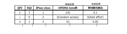
図11は、図10に示す設定に伴って決定されるQFIとIPsecクラスの特性との関係を示す。図11では、IPsecクラス=1に対して、OFDMAのトーン数=242、帯域割当割合=0.1が設定されている。この設定によれば、IPsecクラス=1が割り当てられたQFI=1では、固定的に、242個のRUを用いた無線区間の伝送と、帯域割当割合=0.1による有線区間の伝送とが行われる。
また、IPsecクラス=2が割り当てられたQFI=iでは、ランダムアクセスにより得られたRUでの無線区間の伝送と、ベストエフォートのポリシーに従う有線区間の伝送とが固定的に行われる。更に、IPsecクラス=3が割り当てられたQFI=nでは、52個のRUを用いた無線区間の伝送と、帯域割当割合=0.05による有線区間の伝送とが固定的に行われる。これらの伝送品質は、QFIに割り当てられた5QIの優先度と整合している。このため、本実施形態によれば、5Gで行われる優先制御を、無線LANの通信品質に反映させることができる。
図12は、上記の優先制御が無線LANにおいて実施された場合の動作を説明するタイミングチャートである。この例では、保護対象である無線端末STA1に、RU1が固定的に割り当てられている。このため、DL-MUの通信タイミングで、STA1は常にAPからデータを受け取ることができている。また、UL-MUの通信タイミングにおいても、STA1は常にAPにデータを送信できている。更に、この制御によれば、UL-MUでのデータの衝突が回避されるため、STA1の通信品質の維持に加えて、全体としての通信効率の改善をも実現することができる。
図13は、上記の優先制御の結果、無線LANの通信エリアにおいても、安定したスループットが確保できた様子を示している。保護対象の無線端末については、固定的に優先制御が実施されるため、無線LANの通信エリア内に存在する無線端末の数が増えても、その通信品質は安定的に良好に維持される。このように、本実施形態によれば、5Gの優先制御と無線LANの優先制御とを適切に連携させることができる。
図14は、本実施形態における制御装置22の構成を機能的に表したブロック図である。制御装置22は、各種のインターフェース、メモリ装置、演算装置などのハードウェアに、ソフトウェアを組み合わせることで実現されるサーバーであり、その機能は、図14に示すように表すことができる。
図14に示すように、制御装置22は、通信インターフェース部30を備えている。制御装置22は、通信インターフェース部30を介して5GC24と通信することができる。
通信インターフェース部30は、5GC24から得た情報を情報収集部32に提供することができる。情報収集部32は、具体的には、5Gと無線LANとの間での無線端末UEの受け渡しに関する情報を収集する。また、情報収集部32は、夫々の無線端末UEについてアプリケーション毎のQoS情報を収集する。
情報収集部32が収集した情報は、データベース部34に保存される。データベース部34は、無線LAN優先制御設定部36に対して、保存情報を提供することができる。
無線LAN優先制御設定部36は、無線端末UEの夫々につき、最も優先度の高い5QIに対応させて、無線LANの無線区間および有線区間の夫々における優先条件を設定する。より具体的には、図9乃至図11を参照して説明した通り、5QIに対応させて、OFDMAにおけるトーン数(RUの割り当て)を設定し、また、有線区間の帯域割当割合を設定する。
制御装置22は、更に、無線LAN優先制御指示部38を備えている。無線LAN優先制御指示部38は、5Gから無線LANへのUEの受け渡しが生じたら、そのUEに関する優先情報を通信インターフェース部30を介してAP18に提供する。具体的には、無線LANに受け渡されたUEのアプリケーションについて、設定されたリソースユニットRUと帯域割当割合とを確保する旨の指令がAP18に提供される。
図15は、制御装置22が、上記の機能を実現するために実行する処理のフローチャートである。このルーチンによれば、制御装置22は、先ず、5Gで通信中のUEについて、アプリケーション毎に、5QIに対応する優先条件が設定される(ステップ100)。具体的には、無線LANで割り当てるOFDMAのトーン数、並びに優先区間における帯域割当割合が設定される。
次に、保護対象の無線端末UEが、5Gから無線LANに受け渡された(ハンドオーバーされた)か否かが判別される(ステップ102)。
受け渡しが生じていないと判別された場合は、次に、保護対象の無線端末UEが、無線LANから5Gに受け渡された(ハンドオーバーされた)か否かが判別される(ステップ104)。
受け渡しが認められない場合は、再びステップ102以降の処理が繰り返される。そして、ステップ102において、5Gから無線LANへの受け渡しが認められると、次に、保護対象の無線端末UEの優先通信を確保する指示がAP18に与えられる(ステップ106)。
保護対象のUEが無線LANのエリアに留まっている間は、ステップ102および104の処理が繰り返される。そして、そのUEが、無線LANの通信エリアを出て5Gに受け渡されると、ステップ104において、その受け渡しが認識される。この場合、次に、保護対象のUEについての優先解放がAP18に指示される(ステップ108)。
AP18は、上記の指示を受けて、保護対象のUEについて固定的な優先制御を実施する。これにより、本実施形態によれば、上記図12および図13を参照して説明したように、無線LANのエリアにおいても、保護対象のUEについて、5Gと遜色のない通信品質を安定的に確保することができる。
[実施の形態1の変形例]
ところで、上述した実施の形態1では、AP18をN3IWF26に接続させることとしているが、その構成はこれに限定されるものではない。例えば、図16に示すように、AP18は、L3SW40を介して他のネットワークに配置することとしてもよい。
ところで、上述した実施の形態1では、AP18をN3IWF26に接続させることとしているが、その構成はこれに限定されるものではない。例えば、図16に示すように、AP18は、L3SW40を介して他のネットワークに配置することとしてもよい。
また、上述した実施の形態1では、移動体通信サービスを5Gのサービスに限定しているが、本発明はこれに限定されるものではない。本発明は、保護対象の無線端末に対して優先制御を実施する移動体通信サービスに、広く適用することができる。同様に、実施の形態1では、無線LANの通信システムをWiFi6に限定しているが、本発明の適用はこれに限定されるものではない。本発明は、保護対象の無線端末に通信リソースを優先的に割り当てることのできる無線LANのシステムに広く適用することができる。
また、上述した実施の形態1では、無線LANに受け渡された保護対象の無線端末に、固定的にOFDMAのトーン数を割り当て、かつ、固定的に帯域割当割合を付与することとしている。割り当てられるトーン数および帯域割当割合は、5QIに対して一義的に決定されていてもよいが、保護対象の端末が同時に複数存在する場合に備えて、それらは流動的に設定することとしてもよい。この場合、保護対象の無線端末の全てが適切に優先されるように、5QIに基づいて各無線端末の優先順位を決定し、その優先順位に従って個々の保護対象に与えるトーン数および帯域割当割合を設定することが望ましい。
また、上述した実施の形態1では、OFDMAのトーン数、並びに帯域割当割合を、保護対象の無線端末に優先的に割り振ることで優先制御を実現することとしている。しかしながら、優先制御のために割り振る対象は、トーン数や帯域割当割合に限定されるものではなく、無線LANの通信に必要なリソースであれば広くその対象とすることができる。
また、上述した実施の形態1では、無線LANに受け渡された後に、一台のUEに対して一種類の優先制御を実行することとしている。しかしながら、本発明の適用はこれに限定されるものではない。無線LANの機能において可能である限りは、無線LANに受け渡された後に、SDF毎に異なる優先制御を実施することとしてもよい。
10 第1基地局
14 第2基地局
18 AP
20、STA1、STA2、STA3、STA4、STA5、UE 無線端末
22 制御装置
30 通信インターフェース部
32 情報収集部
34 データベース部
36 無線LAN優先制御設定部
38 無線LAN優先制御指示部
14 第2基地局
18 AP
20、STA1、STA2、STA3、STA4、STA5、UE 無線端末
22 制御装置
30 通信インターフェース部
32 情報収集部
34 データベース部
36 無線LAN優先制御設定部
38 無線LAN優先制御指示部
Claims (8)
- 移動体通信の基地局を介してデータネットワークと無線端末との間でサービスデータフローを授受する移動体通信ステップと、
前記移動体通信から無線LANへの前記無線端末の受け渡しと、その逆の受け渡しとを検知するステップと、
前記無線端末が前記無線LANに受け渡された後、前記移動体通信に受け渡されるまで、無線LANのアクセスポイントを介して前記データネットワークと前記無線端末との間で前記サービスデータフローを授受する無線LAN通信ステップと、を含み、
前記移動体通信ステップは、
通信品質を表すインジケータを、前記サービスデータフローに割り当てるステップと、
前記インジケータに対応する通信品質が実現されるように、前記基地局を介して前記データネットワークと前記無線端末との間で前記サービスデータフローを通信するステップと、を含み、
前記無線LAN通信ステップは、
前記無線LANに受け渡された前記無線端末に割り当てるべき無線LANの周波数リソースを、前記インジケータに基づいて設定する優先制御設定ステップと、
前記無線端末が前記無線LANに受け渡された後に、前記設定に従って前記アクセスポイントを介して前記データネットワークと前記無線端末との間で前記サービスデータフローを通信するステップと、
前記無線端末が前記移動体通信に受け渡された際に、前記設定を解放するステップと、を含む
無線通信システム連携方法。 - 前記移動体通信は、第5世代の移動体通信規格に準拠しており、
前記インジケータは5G QoSインジケータであり、
前記無線LANは、IEEE 802.11axの規格に準拠したWiFi6である
請求項1に記載の無線通信システム連携方法。 - 前記周波数リソースは、前記無線端末と前記アクセスポイントとの間の無線区間の通信を担うOFDMAサブキャリアのトーン数である請求項2に記載の無線通信システム連携方法。
- 前記優先制御設定ステップは、
前記無線LANに受け渡された前記無線端末について、前記アクセスポイントと前記データネットワークとの間の有線区間で確保するべき帯域割当割合を、前記インジケータに基づいて設定するステップを更に含む請求項1乃至3の何れか1項に記載の無線通信システム連携方法。 - 移動体通信の基地局を介してデータネットワークと無線端末との間でサービスデータフローを授受する移動体通信システムと、無線LANのアクセスポイントを介して前記データネットワークと前記無線端末との間で前記サービスデータフローを授受する無線LANの通信システムとの連携を制御する無線通信システム制御装置であって、
前記移動体通信のコアネットワーク並びに前記アクセスポイントとの通信を可能とする通信インターフェース部と、
前記移動体通信から前記無線LANへの前記無線端末の受け渡しと、その逆の受け渡しとに関する情報、並びに前記移動体通信において要求される通信品質を表すために前記サービスデータフローに割り当てられるインジケータに関する情報を、前記通信インターフェース部を介して収集する情報収集部と、
前記無線LANに受け渡された前記無線端末に割り当てるべき無線LANの周波数リソースを、前記インジケータに基づいて設定する無線LAN優先制御設定部と、
前記無線端末が前記無線LANに受け渡された際に前記無線LAN優先制御設定部による設定を前記アクセスポイントに指示すると共に、前記無線端末が前記移動体通信に受け渡された際に当該設定を解放する無線LAN優先制御指示部と、
を備える無線通信システム制御装置。 - 前記移動体通信は、第5世代の移動体通信規格に準拠しており、
前記インジケータは5G QoSインジケータであり、
前記無線LANは、IEEE 802.11axの規格に準拠したWiFi6である
請求項5に記載の無線通信システム制御装置。 - 前記周波数リソースは、前記無線端末と前記アクセスポイントとの間の無線区間の通信を担うOFDMAサブキャリアのトーン数である請求項6に記載の無線通信システム制御装置。
- 無線LAN優先制御設定部は、前記無線LANに受け渡された前記無線端末について、前記アクセスポイントと前記データネットワークとの間の有線区間で確保するべき帯域割当割合を、前記インジケータに基づいて更に設定する請求項5乃至7の何れか1項に記載の無線通信システム制御装置。
Priority Applications (3)
| Application Number | Priority Date | Filing Date | Title |
|---|---|---|---|
| PCT/JP2020/032078 WO2022044136A1 (ja) | 2020-08-25 | 2020-08-25 | 無線通信システム連携方法および無線通信システム制御装置 |
| JP2022544948A JP7416266B2 (ja) | 2020-08-25 | 2020-08-25 | 無線通信システム連携方法および無線通信システム制御装置 |
| US18/022,265 US20230328595A1 (en) | 2020-08-25 | 2020-08-25 | Wireless communication system linking method and wireless communication system controller |
Applications Claiming Priority (1)
| Application Number | Priority Date | Filing Date | Title |
|---|---|---|---|
| PCT/JP2020/032078 WO2022044136A1 (ja) | 2020-08-25 | 2020-08-25 | 無線通信システム連携方法および無線通信システム制御装置 |
Publications (1)
| Publication Number | Publication Date |
|---|---|
| WO2022044136A1 true WO2022044136A1 (ja) | 2022-03-03 |
Family
ID=80352832
Family Applications (1)
| Application Number | Title | Priority Date | Filing Date |
|---|---|---|---|
| PCT/JP2020/032078 Ceased WO2022044136A1 (ja) | 2020-08-25 | 2020-08-25 | 無線通信システム連携方法および無線通信システム制御装置 |
Country Status (3)
| Country | Link |
|---|---|
| US (1) | US20230328595A1 (ja) |
| JP (1) | JP7416266B2 (ja) |
| WO (1) | WO2022044136A1 (ja) |
Cited By (1)
| Publication number | Priority date | Publication date | Assignee | Title |
|---|---|---|---|---|
| CN120264338A (zh) * | 2025-04-10 | 2025-07-04 | 惠州市金信同芳科技有限公司 | 一种基于WiFi6的数据通信方法及系统 |
Citations (1)
| Publication number | Priority date | Publication date | Assignee | Title |
|---|---|---|---|---|
| JP2018139425A (ja) * | 2013-07-01 | 2018-09-06 | クゥアルコム・インコーポレイテッドQualcomm Incorporated | セルラーネットワーク上のベアラに関連したトラフィックのためのWLANにおけるサービス品質(QoS)を有効化するための技法 |
Family Cites Families (6)
| Publication number | Priority date | Publication date | Assignee | Title |
|---|---|---|---|---|
| US8175032B2 (en) * | 2006-09-08 | 2012-05-08 | Clearwire Ip Holdings Llc | System and method for radio frequency resource allocation |
| WO2015152779A1 (en) * | 2014-04-03 | 2015-10-08 | Telefonaktiebolaget Lm Ericsson (Publ) | Method and arrangement for scheduling in shared communication networks |
| WO2016037333A1 (en) * | 2014-09-11 | 2016-03-17 | Telefonaktiebolaget L M Ericsson (Publ) | Fast wifi to lte handover |
| EP3963565A4 (en) * | 2019-05-01 | 2022-10-12 | Magic Leap, Inc. | CONTENT DELIVERY SYSTEM AND PROCEDURES |
| EP4039024A1 (en) * | 2019-09-30 | 2022-08-10 | Telefonaktiebolaget LM Ericsson (publ) | Uplink resource configuration |
| US20210329499A1 (en) * | 2020-06-24 | 2021-10-21 | Necati Canpolat | Enhanced quality of service for 5g wireless communications |
-
2020
- 2020-08-25 WO PCT/JP2020/032078 patent/WO2022044136A1/ja not_active Ceased
- 2020-08-25 US US18/022,265 patent/US20230328595A1/en not_active Abandoned
- 2020-08-25 JP JP2022544948A patent/JP7416266B2/ja active Active
Patent Citations (1)
| Publication number | Priority date | Publication date | Assignee | Title |
|---|---|---|---|---|
| JP2018139425A (ja) * | 2013-07-01 | 2018-09-06 | クゥアルコム・インコーポレイテッドQualcomm Incorporated | セルラーネットワーク上のベアラに関連したトラフィックのためのWLANにおけるサービス品質(QoS)を有効化するための技法 |
Non-Patent Citations (2)
| Title |
|---|
| ANONYMOUS: "IEEE 802.11ax: The Sixth Generation of Wi-Fi", TECHNICAL WHITE PAPER, CISCO JP, vol. c11-740788, 1 June 2018 (2018-06-01), pages 1 - 15, XP055910210 * |
| MATSUBARA TOMOMI: "Toward the coexistence of WiFi 6 and 5G", JANOG44, CISCO SYSTEMS GK, JP, 25 July 2019 (2019-07-25), JP, pages 1 - 39, XP055910204, Retrieved from the Internet <URL:https://www.janog.gr.jp/meeting/janog44/application/files/4815/6352/1493/JANOG44_WiFi6-5G_PDF.pdf> [retrieved on 20220407] * |
Cited By (1)
| Publication number | Priority date | Publication date | Assignee | Title |
|---|---|---|---|---|
| CN120264338A (zh) * | 2025-04-10 | 2025-07-04 | 惠州市金信同芳科技有限公司 | 一种基于WiFi6的数据通信方法及系统 |
Also Published As
| Publication number | Publication date |
|---|---|
| US20230328595A1 (en) | 2023-10-12 |
| JP7416266B2 (ja) | 2024-01-17 |
| JPWO2022044136A1 (ja) | 2022-03-03 |
Similar Documents
| Publication | Publication Date | Title |
|---|---|---|
| López-Raventós et al. | Multi-link operation in IEEE 802.11 be WLANs | |
| EP4521816B1 (en) | Wireless communication method using enhanced distributed channel access, and wireless communication terminal using same | |
| CN107615870B (zh) | 用于上行链路laa的lbt信道接入过程的方法、无线装置以及存储器 | |
| JP6006343B2 (ja) | 無線通信媒体へのアクセスを制御するための方法およびシステム | |
| López-Raventós et al. | IEEE 802.11 be multi-link operation: When the best could be to use only a single interface | |
| JP2018170759A (ja) | セカンダリチャネル上の基本帯域幅デバイス | |
| EP2050231B1 (en) | Mac protocol for centrally controlled multichannel wireless local area networks | |
| CN103052077B (zh) | 一种无线局域网obss站点空分干扰避免方法 | |
| JP2018512021A (ja) | 無線lanマルチユーザ送信機会においてデータを送信するためのシステムおよび方法 | |
| EP3993488B1 (en) | Method for scheduling time delay sensitivity service reporting and method for reporting time delay sensitivity service | |
| JP6474903B2 (ja) | 無線通信システムおよび無線通信方法 | |
| US20170359819A1 (en) | Neighborhood Awareness Network and Multi-Channel Operation over OFDMA | |
| WO2016136724A1 (ja) | 無線通信システムおよび無線通信方法 | |
| CN108476476B (zh) | 功率指示系统和方法 | |
| JP2018521518A (ja) | データ伝送方法、データ伝送装置及びシステム | |
| WO2023066181A1 (zh) | 业务优先级确定方法以及相关装置 | |
| JP7416266B2 (ja) | 無線通信システム連携方法および無線通信システム制御装置 | |
| JP7435798B2 (ja) | 無線通信システム連携方法および無線通信システム制御装置 | |
| EP4709018A1 (en) | Method for transmitting and receiving data in wireless communication system, and wireless communication terminal using same | |
| JP2020080489A (ja) | 無線lanシステムおよび干渉制御方法 | |
| WO2024055241A1 (zh) | 通信方法、终端设备以及网络设备 | |
| Gao et al. | Channel resource allocation for VoIP applications in collaborative IEEE 802.11/802.16 networks | |
| Gao et al. | Medium access cooperations for improving VoIP capacity over hybrid 802.16/802.11 cognitive radio networks | |
| Wong et al. | LTE in the Unlicensed Band (LTE-U) |
Legal Events
| Date | Code | Title | Description |
|---|---|---|---|
| 121 | Ep: the epo has been informed by wipo that ep was designated in this application |
Ref document number: 20951390 Country of ref document: EP Kind code of ref document: A1 |
|
| ENP | Entry into the national phase |
Ref document number: 2022544948 Country of ref document: JP Kind code of ref document: A |
|
| NENP | Non-entry into the national phase |
Ref country code: DE |
|
| 122 | Ep: pct application non-entry in european phase |
Ref document number: 20951390 Country of ref document: EP Kind code of ref document: A1 |