WO2022039122A1 - タービン設備およびタービン設備の検査方法 - Google Patents
タービン設備およびタービン設備の検査方法 Download PDFInfo
- Publication number
- WO2022039122A1 WO2022039122A1 PCT/JP2021/029878 JP2021029878W WO2022039122A1 WO 2022039122 A1 WO2022039122 A1 WO 2022039122A1 JP 2021029878 W JP2021029878 W JP 2021029878W WO 2022039122 A1 WO2022039122 A1 WO 2022039122A1
- Authority
- WO
- WIPO (PCT)
- Prior art keywords
- turbine
- shield
- shields
- turbine equipment
- concrete
- Prior art date
- Legal status (The legal status is an assumption and is not a legal conclusion. Google has not performed a legal analysis and makes no representation as to the accuracy of the status listed.)
- Ceased
Links
Images




Classifications
-
- F—MECHANICAL ENGINEERING; LIGHTING; HEATING; WEAPONS; BLASTING
- F01—MACHINES OR ENGINES IN GENERAL; ENGINE PLANTS IN GENERAL; STEAM ENGINES
- F01D—NON-POSITIVE DISPLACEMENT MACHINES OR ENGINES, e.g. STEAM TURBINES
- F01D25/00—Component parts, details, or accessories, not provided for in, or of interest apart from, other groups
-
- F—MECHANICAL ENGINEERING; LIGHTING; HEATING; WEAPONS; BLASTING
- F01—MACHINES OR ENGINES IN GENERAL; ENGINE PLANTS IN GENERAL; STEAM ENGINES
- F01D—NON-POSITIVE DISPLACEMENT MACHINES OR ENGINES, e.g. STEAM TURBINES
- F01D25/00—Component parts, details, or accessories, not provided for in, or of interest apart from, other groups
- F01D25/28—Supporting or mounting arrangements, e.g. for turbine casing
-
- F—MECHANICAL ENGINEERING; LIGHTING; HEATING; WEAPONS; BLASTING
- F01—MACHINES OR ENGINES IN GENERAL; ENGINE PLANTS IN GENERAL; STEAM ENGINES
- F01D—NON-POSITIVE DISPLACEMENT MACHINES OR ENGINES, e.g. STEAM TURBINES
- F01D9/00—Stators
-
- F—MECHANICAL ENGINEERING; LIGHTING; HEATING; WEAPONS; BLASTING
- F01—MACHINES OR ENGINES IN GENERAL; ENGINE PLANTS IN GENERAL; STEAM ENGINES
- F01K—STEAM ENGINE PLANTS; STEAM ACCUMULATORS; ENGINE PLANTS NOT OTHERWISE PROVIDED FOR; ENGINES USING SPECIAL WORKING FLUIDS OR CYCLES
- F01K13/00—General layout or general methods of operation of complete plants
-
- G—PHYSICS
- G21—NUCLEAR PHYSICS; NUCLEAR ENGINEERING
- G21C—NUCLEAR REACTORS
- G21C13/00—Pressure vessels; Containment vessels; Containment in general
-
- G—PHYSICS
- G21—NUCLEAR PHYSICS; NUCLEAR ENGINEERING
- G21D—NUCLEAR POWER PLANT
- G21D5/00—Arrangements of reactor and engine in which reactor-produced heat is converted into mechanical energy
- G21D5/04—Reactor and engine not structurally combined
- G21D5/06—Reactor and engine not structurally combined with engine working medium circulating through reactor core
-
- G—PHYSICS
- G21—NUCLEAR PHYSICS; NUCLEAR ENGINEERING
- G21F—PROTECTION AGAINST X-RADIATION, GAMMA RADIATION, CORPUSCULAR RADIATION OR PARTICLE BOMBARDMENT; TREATING RADIOACTIVELY CONTAMINATED MATERIAL; DECONTAMINATION ARRANGEMENTS THEREFOR
- G21F1/00—Shielding characterised by the composition of the materials
- G21F1/02—Selection of uniform shielding materials
- G21F1/04—Concretes; Other hydraulic hardening materials
-
- G—PHYSICS
- G21—NUCLEAR PHYSICS; NUCLEAR ENGINEERING
- G21F—PROTECTION AGAINST X-RADIATION, GAMMA RADIATION, CORPUSCULAR RADIATION OR PARTICLE BOMBARDMENT; TREATING RADIOACTIVELY CONTAMINATED MATERIAL; DECONTAMINATION ARRANGEMENTS THEREFOR
- G21F3/00—Shielding characterised by its physical form, e.g. granules, or shape of the material
-
- Y—GENERAL TAGGING OF NEW TECHNOLOGICAL DEVELOPMENTS; GENERAL TAGGING OF CROSS-SECTIONAL TECHNOLOGIES SPANNING OVER SEVERAL SECTIONS OF THE IPC; TECHNICAL SUBJECTS COVERED BY FORMER USPC CROSS-REFERENCE ART COLLECTIONS [XRACs] AND DIGESTS
- Y02—TECHNOLOGIES OR APPLICATIONS FOR MITIGATION OR ADAPTATION AGAINST CLIMATE CHANGE
- Y02E—REDUCTION OF GREENHOUSE GAS [GHG] EMISSIONS, RELATED TO ENERGY GENERATION, TRANSMISSION OR DISTRIBUTION
- Y02E30/00—Energy generation of nuclear origin
-
- Y—GENERAL TAGGING OF NEW TECHNOLOGICAL DEVELOPMENTS; GENERAL TAGGING OF CROSS-SECTIONAL TECHNOLOGIES SPANNING OVER SEVERAL SECTIONS OF THE IPC; TECHNICAL SUBJECTS COVERED BY FORMER USPC CROSS-REFERENCE ART COLLECTIONS [XRACs] AND DIGESTS
- Y02—TECHNOLOGIES OR APPLICATIONS FOR MITIGATION OR ADAPTATION AGAINST CLIMATE CHANGE
- Y02E—REDUCTION OF GREENHOUSE GAS [GHG] EMISSIONS, RELATED TO ENERGY GENERATION, TRANSMISSION OR DISTRIBUTION
- Y02E30/00—Energy generation of nuclear origin
- Y02E30/30—Nuclear fission reactors
Definitions
- the present invention relates to turbine equipment and a method for inspecting turbine equipment used in a boiling water reactor (hereinafter referred to as BWR: Boiling water reactor).
- Patent Document 1 for the purpose of disassembling and reassembling only the central shield plate and the inner shield plate, leaving the outer shield plate in the installed state, abolishing disassembly and reassembly, and shortening the periodic inspection period.
- the low-voltage shield plate changed the contact structure between the middle shield plate and the outer shield plate, disassembled in the order of the central shield plate and the middle shield plate, and the outer shield plate remains installed. It is stated that.
- Patent Document 2 for the purpose of improving the workability and reliability of the pair of divided casings, a through hole is formed in the divided casing, and the through hole is formed on the side of the divided casing joint surface from the through hole.
- a large-diameter counterbore is formed, and a bulge having a larger diameter than the through hole and a smaller diameter than the counterbore is provided on both tightening bolts to be inserted into the through hole, and this bolt is attached to one end of both tightening bolts.
- a nut having almost the same strength can be fixed, and the bulging part of the double tightening bolt is locked to one of the counterbore parts of the split casing, and from the outside of one side of the split casing to one end of the double tightening bolt.
- BWR boiling water reactor
- Turbine equipment in a nuclear power plant drives a generator by receiving high-pressure steam and rotating at high speed. Therefore, in order for the turbine equipment to maintain the specified performance, the turbine is installed during periodic inspections of the nuclear power plant. It is necessary to open the concrete shield and inspect and repair the rotating blades and rotors.
- the present invention provides a turbine equipment and a method for inspecting turbine equipment, which can make the building smaller than the conventional one.
- the present invention includes a plurality of means for solving the above problems, and one example thereof is a turbine facility for a boiling water reactor, which comprises a turbine and a plurality of shields covering the turbine.
- the plurality of shields are characterized in that each has a laminated structure with respect to the other shields.
- the building can be made smaller than before. Issues, configurations and effects other than those mentioned above will be clarified by the description of the following examples.
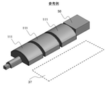
- FIG. 1 is a diagram showing an outline of the turbine equipment of the reference example
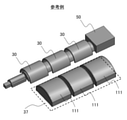
- FIG. 2 is a diagram showing an outline of the turbine equipment of the reference example before inspection
- FIG. 3 is a diagram showing an outline of the turbine equipment of the reference example at the time of inspection
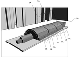
- FIG. 4 is a diagram showing an outline of the turbine equipment of the present invention
- FIG. 5 is a diagram showing an outline of the turbine equipment of the present invention before inspection
- FIG. 6 is a diagram showing an outline of the turbine equipment of the present invention at the time of inspection.
- the turbine equipment of the present invention is suitably applied to a newly installed BWR, ABWR (Advanced Boiling Water Reactor: improved boiling water reactor), and a derivative type reactor of BWR.
- BWR Advanced Boiling Water Reactor: improved boiling water reactor
- a high-pressure turbine 40 and a plurality of (three in FIG. 1) low-pressure turbines 30 are placed on the floor 122 from the upstream side where steam flows.
- the generators 50 are arranged in this order.
- the rotor is placed in the rotor mounting space 32 of the temporary storage space 3, and the diaphragm mounting space is used.
- a diaphragm is placed in 34, an upper casing is placed in the upper casing mounting space 35, a lower casing is placed in the lower casing mounting space 36, and a concrete shield 111 or the like is placed in the concrete shield mounting space 37.
- FIG. 1 describes the case of the low pressure turbine 30. Further, FIG. 1, FIG. 2, and FIG. 3 show a case where the position of the concrete shield mounting space 37 is different.
- the casing itself of the high pressure turbine 40 and the low pressure turbine 30 is provided with shielding performance, or the circumference of the high pressure turbine 40 and the low pressure turbine 30 is concrete.
- a structure such as surrounding with a shield is used.
- a high-pressure turbine 40 and a plurality of (three in FIG. 1) low-pressure turbines 30 are placed on the floor 22 from the upstream side where steam flows in. , The point that the generators 50 are arranged in this order is the same. Further, the low pressure turbine 30 is covered with a concrete shield body 1A on the floor 22.
- the concrete shield body 1A of the low pressure turbine 30 having a radiation shielding function is used as a shielding body.
- the concrete shield 1A has a structure in which a plurality of low-pressure turbines 30 are covered in the axial direction of the low-pressure turbine 30.
- each of the concrete shields 1A in the turbine equipment 100 of this embodiment has a laminated structure with respect to the other concrete shields 1A.
- the concrete shield 1A will be installed on the predetermined low pressure turbine 30.
- a plurality of low-pressure turbines 30 are sequentially disassembled and inspected. Needs to be temporarily removed.
- the concrete shield 1A of the target low-pressure turbine 30 not the temporary storage space 4, but as shown in FIG. 6, the concrete shield of the low-pressure turbine 30 in the other uninspected portion that is not the target of disassembly / inspection. Laminate on 1A. After the inspection of the target low-pressure turbine 30 is completed, the concrete shield 1A is returned to the original low-pressure turbine 30.
- the main parts to be placed in the temporary storage space 4 at the time of periodic inspection are the rotor, the upper casing, the lower casing, and the diaphragm of the target low-pressure turbine 30. Will be.
- FIGS. 7 to 9 is a diagram showing an outline of a shielding structure among the turbine equipment of the present invention
- FIG. 8 is a diagram showing details of a concrete shielding body having a laminated structure
- FIG. 9 is a diagram showing a laminated state. ..
- the concrete shield 1A has a structure in which a plurality of low-pressure turbines 30 are covered from above the casing in the axial direction of the low-pressure turbine 30, but among the concrete shields 1A, adjacent concretes are covered.
- a key structure 10 is provided at the contact portion with the shield 1A as a measure against radiation leakage. This key structure 10 does not prevent the leakage of radioactive substances, but prevents the leakage of radiation that draws a substantially linear locus. Therefore, if the structure has a radial overlap portion of the low pressure turbine 30. good.
- each of the concrete shields 1A has a thickness of the foundation portion 7A in the radial direction of the low pressure turbine 30 as compared with the arch portion 6 covering the upper part of the low pressure turbine 30. It has a thick structure.
- the key structure convex portion 8A is provided on the upper side of the foundation portion 7A of the concrete shield body 1A, and the key structure concave portion 8B is provided on the lower side of the foundation portion 7B. It has a structure that prevents lateral displacement when it occurs.
- the key structure convex portion 8A and the key structure concave portion 8B for preventing lateral displacement can also be used for positioning when the concrete shield body 1A is attached.
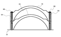
- FIGS. 10 to 12 is a diagram showing an outline of other forms of a concrete shield among turbine equipment
- FIG. 11 is a diagram showing details of a concrete shield having a laminated structure
- FIG. 12 is a diagram showing a laminated state. be.
- the concrete shield 1B shown in FIG. 10 has a radiation shielding function similar to the concrete shield 1A shown in FIG. 7 and the like, and covers the low pressure turbine 30 with a plurality of sheets in the axial direction of the low pressure turbine 30. Is. Further, a key structure 10 is provided as a measure against radiation leakage.
- the concrete shield 1B shown in FIGS. 10 and 11 has a bolt hole 9A in the foundation portion 7B instead of the key structure convex portion 8A and the key structure concave portion 8B of the concrete shield body 1A.
- the bolt hole 9A is formed when the concrete shield 1B removed from the low-pressure turbine 30 to be inspected is laminated on the concrete shield 1B of the low-pressure turbine 30 not to be inspected.
- the concrete shield 1B laminated by the bolt 9B is provided to prevent lateral displacement.
- the turbine equipment 100 of the present embodiment described above is for a boiling water reactor, and includes a low pressure turbine 30 and a plurality of concrete shields covering the low pressure turbine 30, and the plurality of concrete shields are each other. It has a laminated structure with respect to the concrete shield.
- the concrete shields are the concrete shields 1A and 1B that cover the casing of the low pressure turbine 30.
- the concrete shield mounting space 37 can be reduced as compared with the temporary storage space 3 when the conventional shield is used, so that the space required for the temporary shield 4 can be reduced. Therefore, the laydown flat area of the building that houses the turbine equipment 100 becomes small, and the building area of the building itself can be reduced as compared with the conventional building. Therefore, it is possible to contribute to the reduction of the construction cost of the nuclear power plant.
- the shield has a key structure convex portion 8A and a key structure concave portion 8B, or the concrete shield has a bolt hole 9A, so that concrete is used when an earthquake occurs during stacking. It is possible to prevent unexpected situations such as the shield from slipping off.
- the shield covers the low pressure turbine 30 with a plurality of concrete shields 1A and 1B in the axial direction of the low pressure turbine 30, and each of the concrete shields 1A and 1B is provided with the key structure 10. Therefore, it is not necessary to take measures against radiation leakage other than the concrete shields 1A and 1B, and the structure of the turbine equipment 100 can be further simplified.
- the radial thickness of the low-pressure turbine 30 of the shield is such that the thickness of the foundation portions 7A and 7B is thicker than that of the arch portion 6 covering the upper part of the low-pressure turbine 30, thereby stabilizing the concrete shield during laminating. be able to.
Landscapes
- Engineering & Computer Science (AREA)
- General Engineering & Computer Science (AREA)
- Physics & Mathematics (AREA)
- High Energy & Nuclear Physics (AREA)
- Mechanical Engineering (AREA)
- Plasma & Fusion (AREA)
- Chemical & Material Sciences (AREA)
- Combustion & Propulsion (AREA)
- Buildings Adapted To Withstand Abnormal External Influences (AREA)
Priority Applications (1)
| Application Number | Priority Date | Filing Date | Title |
|---|---|---|---|
| JP2022543935A JP7395757B2 (ja) | 2020-08-17 | 2021-08-16 | タービン設備およびタービン設備の検査方法 |
Applications Claiming Priority (2)
| Application Number | Priority Date | Filing Date | Title |
|---|---|---|---|
| JP2020-137437 | 2020-08-17 | ||
| JP2020137437 | 2020-08-17 |
Publications (1)
| Publication Number | Publication Date |
|---|---|
| WO2022039122A1 true WO2022039122A1 (ja) | 2022-02-24 |
Family
ID=80322830
Family Applications (1)
| Application Number | Title | Priority Date | Filing Date |
|---|---|---|---|
| PCT/JP2021/029878 Ceased WO2022039122A1 (ja) | 2020-08-17 | 2021-08-16 | タービン設備およびタービン設備の検査方法 |
Country Status (2)
| Country | Link |
|---|---|
| JP (1) | JP7395757B2 (https=) |
| WO (1) | WO2022039122A1 (https=) |
Citations (7)
| Publication number | Priority date | Publication date | Assignee | Title |
|---|---|---|---|---|
| JPS59155590U (ja) * | 1983-04-05 | 1984-10-18 | 株式会社東芝 | 原子炉熱遮へい壁 |
| JPS59214791A (ja) * | 1983-05-20 | 1984-12-04 | 株式会社日立製作所 | 原子力タ−ビンの遮蔽構造 |
| US5388130A (en) * | 1993-12-21 | 1995-02-07 | Posta; Bekeny | Steam generator located outside nuclear power plant primary containment |
| JP2000147178A (ja) * | 1998-11-17 | 2000-05-26 | Hitachi Ltd | 沸騰水型原子炉施設のタービン設備における放射線遮へい構造 |
| JP2000162378A (ja) * | 1998-11-27 | 2000-06-16 | Ishikawajima Harima Heavy Ind Co Ltd | コンクリートキャスク |
| JP3174865U (ja) * | 2012-01-30 | 2012-04-12 | 秀一 富田 | 収納容器 |
| US20150357058A1 (en) * | 2014-06-09 | 2015-12-10 | Babcock & Wilcox Mpower, Inc. | Nuclear reactor neutron shielding |
-
2021
- 2021-08-16 WO PCT/JP2021/029878 patent/WO2022039122A1/ja not_active Ceased
- 2021-08-16 JP JP2022543935A patent/JP7395757B2/ja active Active
Patent Citations (7)
| Publication number | Priority date | Publication date | Assignee | Title |
|---|---|---|---|---|
| JPS59155590U (ja) * | 1983-04-05 | 1984-10-18 | 株式会社東芝 | 原子炉熱遮へい壁 |
| JPS59214791A (ja) * | 1983-05-20 | 1984-12-04 | 株式会社日立製作所 | 原子力タ−ビンの遮蔽構造 |
| US5388130A (en) * | 1993-12-21 | 1995-02-07 | Posta; Bekeny | Steam generator located outside nuclear power plant primary containment |
| JP2000147178A (ja) * | 1998-11-17 | 2000-05-26 | Hitachi Ltd | 沸騰水型原子炉施設のタービン設備における放射線遮へい構造 |
| JP2000162378A (ja) * | 1998-11-27 | 2000-06-16 | Ishikawajima Harima Heavy Ind Co Ltd | コンクリートキャスク |
| JP3174865U (ja) * | 2012-01-30 | 2012-04-12 | 秀一 富田 | 収納容器 |
| US20150357058A1 (en) * | 2014-06-09 | 2015-12-10 | Babcock & Wilcox Mpower, Inc. | Nuclear reactor neutron shielding |
Also Published As
| Publication number | Publication date |
|---|---|
| JP7395757B2 (ja) | 2023-12-11 |
| JPWO2022039122A1 (https=) | 2022-02-24 |
Similar Documents
| Publication | Publication Date | Title |
|---|---|---|
| US11742099B2 (en) | Very simplified boiling water reactors for commercial electricity generation | |
| WO2022039122A1 (ja) | タービン設備およびタービン設備の検査方法 | |
| US5737379A (en) | Reactor core shroud repair using thermally tensioned ring to apply compression across shroud vertical seam welds | |
| US6067338A (en) | Reactor core shroud repair using thermally tensioned links to apply compression across shroud vertical seam weld | |
| Kostarev et al. | An advanced seismic analysis of an NPP powerful turbogenerator on an isolation pedestal | |
| Klaerner et al. | Manufacturing and Hydro Testing of a 10 MWe sCO2 Axial Turbine | |
| Saez et al. | Analysis of the turbine deblading in an HTGR with the CATHARE code | |
| Aggarwal et al. | A leak-before-break strategy for CANDU primary piping systems | |
| Buckthorpe et al. | RAPHAEL: Synthesis of achievements on materials and components and future direction | |
| Chernoff et al. | Steam generator replacement overview. | |
| Schneider | A Numerical Comparison of Different Methods for Evaluating Pipe Flanges Under External Loads | |
| Kozluk | Canadian fitness-for-service guidelines | |
| Anandapadmanaban et al. | Life extension of the Fast Breeder Test Reactor | |
| WATAKABE et al. | Seismic qualification of crossover piping systems on a sodium-cooled fast reactor with a seismic isolation system | |
| Chen et al. | Design and Validation on Preload of Manway Bolt for Pressurizer of Nuclear Power Plant Under Hydrotest Condition | |
| JP7232164B2 (ja) | 原子力プラント | |
| Ristic et al. | Operating experience with nuclear power stations in Member States | |
| Kitch | Pump Selection and Application in a Pressurized Water Reactor Electric Generating Plant | |
| Laffont et al. | Status of studies on ASTRID Gas Power Conversion System option | |
| Abel et al. | Applicability of pipelocks as a remedy for intergranular stress corrosion cracking in BWRs | |
| Engel et al. | Design and Analysis of a Full Structural Weld Overlay for a Feedwater Nozzle-to-Safe End Dissimilar Metal Butt Weld | |
| CN119508623A (zh) | 一种适用于直管压力平衡型膨胀节的包覆组件 | |
| Gower et al. | Operating experience | |
| RU108545U1 (ru) | Разгруженный сильфонный компенсатор | |
| Jarman | The Canadian approach to protection against postulated primary heat transport piping failures |
Legal Events
| Date | Code | Title | Description |
|---|---|---|---|
| 121 | Ep: the epo has been informed by wipo that ep was designated in this application |
Ref document number: 21858268 Country of ref document: EP Kind code of ref document: A1 |
|
| ENP | Entry into the national phase |
Ref document number: 2022543935 Country of ref document: JP Kind code of ref document: A |
|
| NENP | Non-entry into the national phase |
Ref country code: DE |
|
| 122 | Ep: pct application non-entry in european phase |
Ref document number: 21858268 Country of ref document: EP Kind code of ref document: A1 |