WO2022034665A1 - Electric motor, drive device, compressor, and air conditioner - Google Patents
Electric motor, drive device, compressor, and air conditioner Download PDFInfo
- Publication number
- WO2022034665A1 WO2022034665A1 PCT/JP2020/030751 JP2020030751W WO2022034665A1 WO 2022034665 A1 WO2022034665 A1 WO 2022034665A1 JP 2020030751 W JP2020030751 W JP 2020030751W WO 2022034665 A1 WO2022034665 A1 WO 2022034665A1
- Authority
- WO
- WIPO (PCT)
- Prior art keywords
- coil
- phase
- phase coil
- coils
- connection
- Prior art date
Links
- 238000004804 winding Methods 0.000 claims description 45
- 230000006835 compression Effects 0.000 claims description 14
- 238000007906 compression Methods 0.000 claims description 14
- 238000010586 diagram Methods 0.000 description 20
- 239000011295 pitch Substances 0.000 description 19
- 239000003507 refrigerant Substances 0.000 description 19
- 230000003313 weakening effect Effects 0.000 description 14
- 238000004378 air conditioning Methods 0.000 description 13
- 230000008901 benefit Effects 0.000 description 10
- 238000003780 insertion Methods 0.000 description 10
- 230000037431 insertion Effects 0.000 description 10
- 230000007423 decrease Effects 0.000 description 8
- 230000007246 mechanism Effects 0.000 description 7
- 230000000052 comparative effect Effects 0.000 description 6
- 230000004907 flux Effects 0.000 description 6
- 230000007935 neutral effect Effects 0.000 description 6
- 238000001816 cooling Methods 0.000 description 5
- XEEYBQQBJWHFJM-UHFFFAOYSA-N Iron Chemical compound [Fe] XEEYBQQBJWHFJM-UHFFFAOYSA-N 0.000 description 4
- 230000008859 change Effects 0.000 description 3
- 238000009826 distribution Methods 0.000 description 3
- 238000011156 evaluation Methods 0.000 description 3
- 238000000034 method Methods 0.000 description 3
- 230000008569 process Effects 0.000 description 3
- RYGMFSIKBFXOCR-UHFFFAOYSA-N Copper Chemical compound [Cu] RYGMFSIKBFXOCR-UHFFFAOYSA-N 0.000 description 2
- 229910052802 copper Inorganic materials 0.000 description 2
- 239000010949 copper Substances 0.000 description 2
- 238000005265 energy consumption Methods 0.000 description 2
- 238000010438 heat treatment Methods 0.000 description 2
- 229910052742 iron Inorganic materials 0.000 description 2
- 230000004888 barrier function Effects 0.000 description 1
- 230000015556 catabolic process Effects 0.000 description 1
- 238000007796 conventional method Methods 0.000 description 1
- 230000006837 decompression Effects 0.000 description 1
- 230000003111 delayed effect Effects 0.000 description 1
- 230000006866 deterioration Effects 0.000 description 1
- 238000007599 discharging Methods 0.000 description 1
- 239000011521 glass Substances 0.000 description 1
- 238000009413 insulation Methods 0.000 description 1
- 238000004519 manufacturing process Methods 0.000 description 1
- 230000004048 modification Effects 0.000 description 1
- 238000012986 modification Methods 0.000 description 1
- 230000000149 penetrating effect Effects 0.000 description 1
- 230000009467 reduction Effects 0.000 description 1
- 238000005057 refrigeration Methods 0.000 description 1
- 238000005096 rolling process Methods 0.000 description 1
- 239000004065 semiconductor Substances 0.000 description 1
- 230000001360 synchronised effect Effects 0.000 description 1
- 238000012546 transfer Methods 0.000 description 1
- 238000003466 welding Methods 0.000 description 1
Images


Classifications
-
- H—ELECTRICITY
- H02—GENERATION; CONVERSION OR DISTRIBUTION OF ELECTRIC POWER
- H02K—DYNAMO-ELECTRIC MACHINES
- H02K3/00—Details of windings
- H02K3/04—Windings characterised by the conductor shape, form or construction, e.g. with bar conductors
- H02K3/28—Layout of windings or of connections between windings
-
- F—MECHANICAL ENGINEERING; LIGHTING; HEATING; WEAPONS; BLASTING
- F04—POSITIVE - DISPLACEMENT MACHINES FOR LIQUIDS; PUMPS FOR LIQUIDS OR ELASTIC FLUIDS
- F04C—ROTARY-PISTON, OR OSCILLATING-PISTON, POSITIVE-DISPLACEMENT MACHINES FOR LIQUIDS; ROTARY-PISTON, OR OSCILLATING-PISTON, POSITIVE-DISPLACEMENT PUMPS
- F04C23/00—Combinations of two or more pumps, each being of rotary-piston or oscillating-piston type, specially adapted for elastic fluids; Pumping installations specially adapted for elastic fluids; Multi-stage pumps specially adapted for elastic fluids
- F04C23/02—Pumps characterised by combination with or adaptation to specific driving engines or motors
-
- H—ELECTRICITY
- H02—GENERATION; CONVERSION OR DISTRIBUTION OF ELECTRIC POWER
- H02K—DYNAMO-ELECTRIC MACHINES
- H02K15/00—Methods or apparatus specially adapted for manufacturing, assembling, maintaining or repairing of dynamo-electric machines
- H02K15/06—Embedding prefabricated windings in machines
- H02K15/062—Windings in slots; salient pole windings
- H02K15/065—Windings consisting of complete sections, e.g. coils, waves
- H02K15/067—Windings consisting of complete sections, e.g. coils, waves inserted in parallel to the axis of the slots or inter-polar channels
- H02K15/068—Strippers
-
- H—ELECTRICITY
- H02—GENERATION; CONVERSION OR DISTRIBUTION OF ELECTRIC POWER
- H02K—DYNAMO-ELECTRIC MACHINES
- H02K21/00—Synchronous motors having permanent magnets; Synchronous generators having permanent magnets
- H02K21/12—Synchronous motors having permanent magnets; Synchronous generators having permanent magnets with stationary armatures and rotating magnets
- H02K21/14—Synchronous motors having permanent magnets; Synchronous generators having permanent magnets with stationary armatures and rotating magnets with magnets rotating within the armatures
-
- H—ELECTRICITY
- H02—GENERATION; CONVERSION OR DISTRIBUTION OF ELECTRIC POWER
- H02K—DYNAMO-ELECTRIC MACHINES
- H02K3/00—Details of windings
- H02K3/04—Windings characterised by the conductor shape, form or construction, e.g. with bar conductors
- H02K3/12—Windings characterised by the conductor shape, form or construction, e.g. with bar conductors arranged in slots
-
- H—ELECTRICITY
- H02—GENERATION; CONVERSION OR DISTRIBUTION OF ELECTRIC POWER
- H02K—DYNAMO-ELECTRIC MACHINES
- H02K3/00—Details of windings
- H02K3/04—Windings characterised by the conductor shape, form or construction, e.g. with bar conductors
- H02K3/18—Windings for salient poles
-
- H—ELECTRICITY
- H02—GENERATION; CONVERSION OR DISTRIBUTION OF ELECTRIC POWER
- H02K—DYNAMO-ELECTRIC MACHINES
- H02K7/00—Arrangements for handling mechanical energy structurally associated with dynamo-electric machines, e.g. structural association with mechanical driving motors or auxiliary dynamo-electric machines
- H02K7/14—Structural association with mechanical loads, e.g. with hand-held machine tools or fans
-
- H—ELECTRICITY
- H02—GENERATION; CONVERSION OR DISTRIBUTION OF ELECTRIC POWER
- H02P—CONTROL OR REGULATION OF ELECTRIC MOTORS, ELECTRIC GENERATORS OR DYNAMO-ELECTRIC CONVERTERS; CONTROLLING TRANSFORMERS, REACTORS OR CHOKE COILS
- H02P25/00—Arrangements or methods for the control of AC motors characterised by the kind of AC motor or by structural details
- H02P25/16—Arrangements or methods for the control of AC motors characterised by the kind of AC motor or by structural details characterised by the circuit arrangement or by the kind of wiring
- H02P25/18—Arrangements or methods for the control of AC motors characterised by the kind of AC motor or by structural details characterised by the circuit arrangement or by the kind of wiring with arrangements for switching the windings, e.g. with mechanical switches or relays
-
- F—MECHANICAL ENGINEERING; LIGHTING; HEATING; WEAPONS; BLASTING
- F04—POSITIVE - DISPLACEMENT MACHINES FOR LIQUIDS; PUMPS FOR LIQUIDS OR ELASTIC FLUIDS
- F04C—ROTARY-PISTON, OR OSCILLATING-PISTON, POSITIVE-DISPLACEMENT MACHINES FOR LIQUIDS; ROTARY-PISTON, OR OSCILLATING-PISTON, POSITIVE-DISPLACEMENT PUMPS
- F04C23/00—Combinations of two or more pumps, each being of rotary-piston or oscillating-piston type, specially adapted for elastic fluids; Pumping installations specially adapted for elastic fluids; Multi-stage pumps specially adapted for elastic fluids
- F04C23/008—Hermetic pumps
-
- F—MECHANICAL ENGINEERING; LIGHTING; HEATING; WEAPONS; BLASTING
- F04—POSITIVE - DISPLACEMENT MACHINES FOR LIQUIDS; PUMPS FOR LIQUIDS OR ELASTIC FLUIDS
- F04C—ROTARY-PISTON, OR OSCILLATING-PISTON, POSITIVE-DISPLACEMENT MACHINES FOR LIQUIDS; ROTARY-PISTON, OR OSCILLATING-PISTON, POSITIVE-DISPLACEMENT PUMPS
- F04C29/00—Component parts, details or accessories of pumps or pumping installations, not provided for in groups F04C18/00 - F04C28/00
- F04C29/0042—Driving elements, brakes, couplings, transmissions specially adapted for pumps
- F04C29/0085—Prime movers
-
- F—MECHANICAL ENGINEERING; LIGHTING; HEATING; WEAPONS; BLASTING
- F04—POSITIVE - DISPLACEMENT MACHINES FOR LIQUIDS; PUMPS FOR LIQUIDS OR ELASTIC FLUIDS
- F04D—NON-POSITIVE-DISPLACEMENT PUMPS
- F04D25/00—Pumping installations or systems
- F04D25/02—Units comprising pumps and their driving means
- F04D25/06—Units comprising pumps and their driving means the pump being electrically driven
Definitions
- This disclosure relates to motors.
- a motor equipped with a three-phase coil attached to a stator core by distributed winding is used (for example, Patent Document 1).
- a motor equipped with a 3-phase coil when the number of windings forming the 3-phase coil (also referred to as stator winding) is large, the motor can be driven with a small current (also referred to as motor current), and an inverter. The loss can be reduced. As a result, the efficiency of the motor (also referred to as motor efficiency) can be increased.
- the number of turns of the winding is large, the induced voltage in the three-phase coil rises, and the rotation speed of the motor may not be increased.
- the number of turns of the winding when the number of turns of the winding is small, the induced voltage in the three-phase coil can be reduced, and the rotation speed of the motor can be increased.
- the purpose of this disclosure is to improve the efficiency of the motor.
- the motor according to one aspect of the present disclosure is A stator core having 6 ⁇ n (n is an integer of 1 or more) slots and a three-phase coil attached to the stator core by distributed winding and forming 2 ⁇ n magnetic poles.
- a connection switching unit for switching the connection state of the three-phase coil between a first connection state and a second connection state different from the first connection state is provided.
- the three-phase coil has 2 ⁇ n U-phase coils, 2 ⁇ n V-phase coils, and 2 ⁇ n W-phase coils at the coil end of the 3-phase coil.
- Each coil of the three-phase coil is arranged in two of the 6 ⁇ n slots every other slot on one end side of the stator core.
- the motor according to another aspect of the present disclosure is A stator core having 9 ⁇ n (n is an integer of 1 or more) slots and a three-phase coil attached to the stator core by distributed winding and forming 4 ⁇ n magnetic poles.
- a connection switching unit for switching the connection state of the three-phase coil between a first connection state and a second connection state different from the first connection state is provided.
- the three-phase coil has 3 ⁇ n U-phase coils, 3 ⁇ n V-phase coils, and 3 ⁇ n W-phase coils at the coil end of the 3-phase coil.
- Each coil of the three-phase coil is arranged in two of the 9 ⁇ n slots every other slot on one end side of the stator core.
- the drive device is With the motor A control device for controlling the connection switching unit is provided.
- the compressor according to another aspect of the present disclosure is With a closed container With the compression device arranged in the closed container, The electric motor for driving the compression device is provided.
- the air conditioner according to another aspect of the present disclosure is With the compressor Equipped with a heat exchanger.
- the efficiency of the motor can be improved.
- FIG. It is a top view which shows schematic structure of the electric motor which concerns on Embodiment 1.
- FIG. It is sectional drawing which shows schematic structure of a rotor. It is a top view which shows the structure of a stator schematically. It is a figure which shows the arrangement of the three-phase coil in a slot. It is a figure which shows typically the arrangement of the three-phase coil at a coil end, and the arrangement of a three-phase coil in a slot. It is a figure which shows the example of the coil connected in series in each phase. It is a figure which shows the example of the coil connected in parallel in each phase. It is a figure which shows the example of the insertion instrument for inserting a three-phase coil into a stator core.
- FIG. 1 It is a figure which shows the example of the process of inserting a three-phase coil into a stator core. It is a figure which shows the example of the process of inserting a three-phase coil into a stator core. It is a block diagram which shows the structure of a drive device. It is a block diagram which shows the structure of a drive device. It is a figure which shows typically the three-phase coil connected by Y connection. It is a figure which shows typically the three-phase coil connected by the delta connection. It is a graph which shows the relationship between the line voltage and the rotation speed in an electric motor. It is a graph which shows the relationship between the line voltage and the rotation speed in an electric motor. It is a graph which shows the relationship between the torque of a motor, and the rotation speed.
- FIG. 22 is a cross-sectional view schematically showing the structure of the rotor of the motor shown in FIG. 22.
- FIG. 22 is a top view schematically showing the structure of the stator of the motor shown in FIG. 22.
- FIG. It is a figure which shows the arrangement of the three-phase coil in the slot of the stator shown in FIG. It is a figure which shows typically the arrangement of the three-phase coil at the coil end of the stator shown in FIG. 24, and the arrangement of the three-phase coil in a slot. It is a top view which shows schematic structure of the electric motor which concerns on Embodiment 4.
- FIG. It is a figure which shows typically the arrangement of the three-phase coil in the coil end of the stator of the motor shown in FIG. 27, and the arrangement of the three-phase coil in a slot.
- It is sectional drawing which shows schematic structure of the compressor which concerns on Embodiment 5.
- FIG. It is a figure which shows schematic the structure of the refrigerating air-conditioning apparatus which concerns on Embodiment 6.
- Embodiment 1 In the xyz Cartesian coordinate system shown in each figure, the z-axis direction (z-axis) indicates a direction parallel to the axis Ax of the electric motor 1, and the x-axis direction (x-axis) is orthogonal to the z-axis direction (z-axis).
- the y-axis direction (y-axis) indicates a direction orthogonal to both the z-axis direction and the x-axis direction.
- the axis Ax is the center of the stator 3 and the center of rotation of the rotor 2.
- the direction parallel to the axis Ax is also referred to as "axial direction of rotor 2" or simply "axial direction”.
- the radial direction is the radial direction of the rotor 2 or the stator 3, and is a direction orthogonal to the axis Ax.
- the xy plane is a plane orthogonal to the axial direction.
- the arrow D1 indicates the circumferential direction about the axis Ax.
- the circumferential direction of the rotor 2 or the stator 3 is also simply referred to as "circumferential direction”.
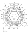
- FIG. 1 is a top view schematically showing the structure of the motor 1 according to the first embodiment.
- the motor 1 has a rotor 2 having a plurality of magnetic poles, a stator 3, and a shaft 4 fixed to the rotor 2.
- the electric motor 1 is, for example, a permanent magnet synchronous motor.
- the rotor 2 is rotatably arranged inside the stator 3. There is an air gap between the rotor 2 and the stator 3. The rotor 2 rotates about the axis Ax.
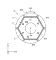
- FIG. 2 is a cross-sectional view schematically showing the structure of the rotor 2.
- the rotor 2 has a rotor core 21 and at least one permanent magnet 22.
- the rotor 2 has 2 ⁇ n (n is an integer of 1 or more) magnetic poles.
- the rotor core 21 has a plurality of magnet insertion holes 211 and a shaft hole 212 in which the shaft 4 is arranged.
- the rotor core 21 may further have at least one flux barrier portion that is a space communicating with each magnet insertion hole 211.
- the rotor 2 has a plurality of permanent magnets 22.
- Each permanent magnet 22 is arranged in each magnet insertion hole 211.
- One permanent magnet 22 forms one magnetic pole of the rotor 2, that is, an N pole or an S pole. However, two or more permanent magnets 22 may form one magnetic pole of the rotor 2.
- one permanent magnet 22 forming one magnetic pole of the rotor 2 is arranged straight in the xy plane.
- a set of permanent magnets 22 forming one magnetic pole of the rotor 2 may be arranged so as to have a V shape.
- each magnetic pole of the rotor 2 is located at the center of each magnetic pole of the rotor 2 (that is, the north pole or the south pole of the rotor 2).
- Each magnetic pole of the rotor 2 (also simply referred to as "each magnetic pole” or “magnetic pole”) means a region serving as an N pole or an S pole of the rotor 2.
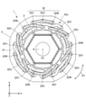
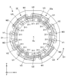
- FIG. 3 is a top view schematically showing the structure of the stator 3.
- FIG. 4 is a diagram showing the arrangement of the three-phase coil 32 in the slot 311.
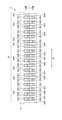
- FIG. 5 is a diagram schematically showing the arrangement of the three-phase coil 32 at the coil end 32a and the arrangement of the three-phase coil 32 in the slot 311.
- the dashed line indicates the coil of each phase at the coil end 32a
- the chain line indicates the boundary between the inner layer and the outer layer in each slot 311.
- the stator 3 has a stator core 31 and a three-phase coil 32 attached to the stator core 31 in a distributed winding manner.
- the stator core 31 has an annular yoke, a plurality of teeth extending radially from the yoke, and 6 ⁇ n (n is an integer of 1 or more) slots 311 in which the three-phase coil 32 is arranged. ..
- Each slot 311 is also referred to as, for example, a first slot, a second slot, ..., Nth slot.
- the three-phase coil 32 (that is, the coil of each phase) has a coil side arranged in the slot 311 and a coil end 32a not arranged in the slot 311. Each coil end 32a is an end portion of the three-phase coil 32 in the axial direction.
- the 3-phase coil 32 has 2 ⁇ n U-phase coils 32U, 2 ⁇ n V-phase coils 32V, and 2 ⁇ n W-phase coils 32W at each coil end 32a.
- the three-phase coil 32 has 2 ⁇ n U-phase coils 32U, 2 ⁇ n V-phase coils 32V, and 2 ⁇ n W-phase coils 32W on the stator core 31. That is, the three-phase coil 32 has three phases, a first phase, a second phase, and a third phase.
- the first phase is the U phase
- the second phase is the V phase
- the third phase is the W phase.
- each of the three phases is referred to as a U phase, a V phase, and a W phase.
- Each U-phase coil 32U, each V-phase coil 32V, and each W-phase coil 32W shown in FIGS. 1 and 3 are also simply referred to as coils.
- n 3. Therefore, in the example shown in FIGS. 1 and 3, at the coil end 32a, the three-phase coil 32 has six U-phase coils 32U, six V-phase coils 32V, and six W-phase coils 32W. ing. However, the number of coils in each phase is not limited to six.
- the stator 3 has the structure shown in FIG. 3 at the two coil ends 32a. However, the stator 3 may have the structure shown in FIG. 3 at one of the two coil ends 32a.
- each coil of the three-phase coil 32 is arranged in the slot 311 at a two-slot pitch on one end side of the stator core 31.
- the 2-slot pitch means "every 2 slots". That is, the two-slot pitch means that one coil is arranged in the slot 311 every two slots. In other words, the two-slot pitch means that one coil is arranged in the slot 311 every other slot. Therefore, as shown in FIGS. 1 and 3, each coil of the three-phase coil 32 is arranged in two slots 311 every other slot on one end side of the stator core 31. In other words, each coil of the three-phase coil 32 is arranged in two slots 311 with one slot 311 interposed therebetween on one end side of the stator core 31.
- each slot 311 As shown in FIGS. 4 and 5, two coils are arranged in each slot 311. Each coil is arranged in each slot 311 along with the coils of the other phases. That is, two coils having different phases are arranged in each slot 311. The coils of each phase are arranged in 6 inner layers and 6 outer layers.
- U-phase coil 32U in slot 311 The arrangement of the U-phase coil 32U in the slot 311 will be specifically described below.
- n U-phase coils 32U are arranged in the outer layer of slot 311.
- the other n U-phase coils 32U of the 2 ⁇ n U-phase coils 32U are arranged in the inner layer of the slot 311.
- three U-phase coils 32U are arranged in the outer layer of slot 311 and the other three U-phase coils 32U are arranged in the inner layer of slot 311.
- V-phase coil 32V in slot 311 The arrangement of the V-phase coil 32V in the slot 311 will be specifically described below.
- a part of the V-phase coil 32V is arranged in the inner layer of the slot 311 in which the U-phase coil 32U is arranged.
- the other part of the V-phase coil 32V is arranged in the outer layer of the slot 311 in which the W-phase coil 32W is arranged. That is, when a part of each V-phase coil 32V is arranged in the outer layer of the slot 311 in which the coil of the other phase is arranged, the other part of each V-phase coil 32V is arranged with the coil of the other phase. It is arranged in the inner layer of the slot 311.
- each V-phase coil 32V When a part of each V-phase coil 32V is arranged in the inner layer of the slot 311 in which the coil of the other phase is arranged, the other part of each V-phase coil 32V is arranged in the coil of the other phase. It is arranged on the outer layer of slot 311.
- n W-phase coils 32W are arranged in the outer layer of the slot 311.
- the other n W-phase coils 32W out of the 2 ⁇ n W-phase coils 32W are arranged in the inner layer of the slot 311.
- three W-phase coils 32W are arranged in the outer layer of slot 311 and the other three W-phase coils 32W are arranged in the inner layer of slot 311.
- n U-phase coils 32U arranged in the outer layer of the slot 311 are arranged at equal intervals in the circumferential direction.
- the n U-phase coils 32U arranged in the inner layer of the slot 311 are arranged at equal intervals in the circumferential direction.
- the 2 ⁇ n V-phase coils 32V are arranged at equal intervals in the circumferential direction.
- the n W-phase coils 32W arranged in the outer layer of the slot 311 are arranged at equal intervals in the circumferential direction.
- the n W-phase coils 32W arranged in the inner layer of the slot 311 are arranged at equal intervals in the circumferential direction.
- kp sin ⁇ P / (Q / S) ⁇ ⁇ ( ⁇ / 2)
- the short node winding coefficient of the distributed winding three-phase coil 32 is a coefficient indicating the ratio of the amount of magnetic flux that one coil can interlink.
- the third-order distributed winding coefficient kd can be obtained by the following equation.
- kd3 ⁇ sin (3 ⁇ ⁇ / 6) ⁇ / [q ⁇ sin ⁇ (3 ⁇ ⁇ / 6) / q ⁇ ]
- delta connection also called delta connection
- a circulating current may be generated in the three-phase coil and the performance of the motor may deteriorate.
- the circulating current is due to the third harmonic component contained in the induced voltage generated in the coil of each phase.
- the stator 3 since the stator 3 has the above-mentioned arrangement of the three-phase coils 32, the induced voltage generated in the coils of each phase does not include the third harmonic component.
- FIG. 6 is a diagram showing an example of coils connected in series in each phase.
- the coils of the stator 3 are connected in series, for example.
- three U-phase coils 32U are connected in series
- three V-phase coils 32V are connected in series
- three W-phase coils 32W are connected in series.
- FIG. 7 is a diagram showing an example of coils connected in parallel in each phase.
- the coils of the stator 3 are connected in parallel, for example.
- three U-phase coils 32U are connected in parallel
- three V-phase coils 32V are connected in parallel
- three W-phase coils 32W are connected in parallel.
- the stator 3 may have an insulating member that insulates the coils of each phase of the three-phase coil 32.
- the insulating member is, for example, insulating paper.
- FIG. 8 is a diagram showing an example of an insertion device 9 for inserting the three-phase coil 32 into the stator core 31.
- 9 and 10 are diagrams showing an example of a process of inserting a three-phase coil into the stator core 31.
- the three-phase coil 32 is attached to, for example, a stator core 31 prepared in advance by an insertion tool 9. In the present embodiment, the three-phase coil 32 is attached to the stator core 31 by distributed winding.
- the three-phase coil 32 is arranged between the blades 91 of the insertion device 9 as shown in FIGS. 9 and 10.
- the blade 91 is inserted inside the stator core 31 together with the three-phase coil 32.
- the three-phase coil 32 is slid in the axial direction and placed in the slot 311.
- the drive device 100 for driving the electric motor 1 is mounted on, for example, an air conditioner (for example, the refrigerating and air-conditioning device 7 described in the sixth embodiment).
- the electric motor 1 is mounted on the air conditioner and used as a drive source for the air conditioner.
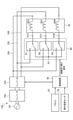
- the drive device 100 determines the connection state between the converter 102 that rectifies the output of the power supply 101, the inverter 103 that applies a voltage (specifically, an AC voltage) to the three-phase coil 32 of the electric motor 1, and the three-phase coil 32. It has a connection switching unit 60 for switching between the connection state of 1 and the connection state of the second, and a control device 50.
- the connection switching unit 60 is also referred to as a connection switching device. Power is supplied to the converter 102 from a power source 101, which is an alternating current (AC) power source.
- AC alternating current
- the first connection state is, for example, a Y connection (also referred to as a star connection).
- the second connection state is different from the first connection state.
- the first connection state is Y connection
- the second connection state is delta connection.
- the connection switching unit 60 switches the connection state of the three-phase coil 32 between the Y connection and the delta connection.
- the motor 1 may have a drive device 100.
- the electric motor 1 may have a part of the components of the drive device 100.
- the electric motor 1 may have a connection switching unit 60, or may have both a connection switching unit 60 and a control device 50.
- the power supply 101 is, for example, an AC power supply of 200 V (effective voltage).
- the converter 102 is a rectifier circuit and outputs a direct current (DC) voltage of, for example, 280V.
- the voltage output from the converter 102 is referred to as a bus voltage.
- a bus voltage is supplied to the inverter 103 from the converter 102, and a line voltage (also referred to as a motor voltage) is output to the three-phase coil 32 of the motor 1.
- Wiring 104, 105, 106 connected to the U-phase coil 32U, the V-phase coil 32V, and the W-phase coil 32W are connected to the inverter 103, respectively.
- the U-phase coil 32U has a terminal 31U.
- the V-phase coil 32V has a terminal 31V.
- the W-phase coil 32W has a terminal 31W.
- the connection switching unit 60 includes a switch 61 (also referred to as a U-phase switch), a switch 62 (also referred to as a V-phase switch), and a switch 63 (also referred to as a W-phase switch).
- the switch 61 connects the terminal 31U of the U-phase coil 32U to the wiring 105 or the neutral point 33.
- the switch 62 connects the terminal 31V of the V-phase coil 32V to the wiring 106 or the neutral point 33.
- the switch 63 connects the terminal 31W of the W-phase coil 32W to the wiring 104 or the neutral point 33.
- each of the switches 61, 62, 63 is a relay contact.
- each of the switches 61, 62, and 63 may be a semiconductor switch.
- the wiring 104 is electrically connected to the U-phase coil 32U and the switch 63.
- the wiring 105 is electrically connected to the V-phase coil 32V and the switch 61.
- the wiring 106 is electrically connected to the W-phase coil 32W and the switch 62.
- the control device 50 controls the inverter 103 and the connection switching unit 60.
- the control device 50 may control the converter 102.
- An operation instruction signal from the remote controller 55 for operating the air conditioner and an indoor temperature detected by the indoor temperature sensor 54 are input to the control device 50.
- the control device 50 outputs a voltage switching signal to the converter 102, outputs an inverter drive signal to the inverter 103, and outputs a connection switching signal to the connection switching unit 60 based on these input information.
- the control device 50 controls the inverter 103 so that the rotation of the electric motor 1 is temporarily stopped before the switching is completed.
- the connection switching unit 60 sets the connection state of the three-phase coil 32 to Y connection.
- the switch 61 connects the terminal 31U of the U-phase coil 32U to the neutral point 33
- the switch 62 connects the terminal 31V of the V-phase coil 32V to the neutral point 33
- the switch 63 connects the terminal 31W of the W-phase coil 32W to the neutral point 33.
- the connection state of the three-phase coil 32 shown in FIG. 11 is Y connection.
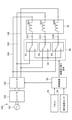
- the switches 61, 62, 63 of the connection switching unit 60 are switched from the state of the switches 61, 62, 63 of the connection switching unit 60 shown in FIG. 11 to the state shown in FIG.
- the connection switching unit 60 sets the connection state of the three-phase coil 32 to delta connection.
- the switch 61 connects the terminal 31U of the U-phase coil 32U to the wiring 105
- the switch 62 connects the terminal 31V of the V-phase coil 32V to the wiring 106
- the switch 63 connects the W-phase coil.
- the 32W terminal 31W is connected to the wiring 104.
- the connection state of the three-phase coil 32 shown in FIG. 12 is a delta connection.
- connection switching unit 60 can switch the connection state of the three-phase coil 32 between the Y connection and the delta connection by switching the switches 61, 62, 63. ..
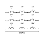
- FIG. 13 is a diagram schematically showing a three-phase coil 32 connected by a Y connection. That is, FIG. 13 is a diagram schematically showing the connection state of the three-phase coil 32 shown in FIG.
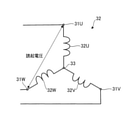
- FIG. 14 is a diagram schematically showing a three-phase coil 32 connected by a delta connection. That is, FIG. 14 is a diagram schematically showing the connection state of the three-phase coil 32 shown in FIG.
- the magnetic flux of the permanent magnet 22 is interlinked with the three-phase coil 32 of the stator 3, and an induced voltage is generated in the three-phase coil 32. ..
- the induced voltage is proportional to the rotation speed of the rotor 2 and also to the number of turns of the three-phase coil 32. The higher the rotation speed of the motor 1 and the larger the number of turns of the three-phase coil 32, the larger the induced voltage.
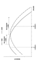
- FIG. 15 is a graph showing the relationship between the line voltage and the rotation speed in the motor 1.
- the rotation speed N1 corresponds to the intermediate condition of the air conditioner (for example, the refrigerating and air-conditioning apparatus 7 described in the sixth embodiment), and the rotation speed N2 corresponds to the rated condition of the air conditioner.
- the delta connection (also referred to as delta connection) lowers the line voltage (also referred to as motor voltage) of the three-phase coil 32 than the Y connection.
- the phase impedance of the 3-phase coil 32 when the connection state of the 3-phase coil 32 is delta connection is 1 / ⁇ 3 times that of the case where the connection state of the 3-phase coil 32 is Y connection when the number of turns is the same. Become. Therefore, as shown in FIG. 15, the line voltage when the connection state of the three-phase coil 32 is delta connection is the case where the connection state of the three-phase coil 32 is Y connection when the rotation speed is the same. It is 1 / ⁇ 3 times the line voltage.
- the line voltage is equivalent to the case of Y connection for the same rotation number N, and therefore.
- the output current of the inverter 103 is also equivalent to that of the Y connection.
- Y connection is often adopted rather than delta connection for the following reasons.
- the delta connection has a larger number of coil turns than the Y connection, so that the time required for winding the three-phase coil in the manufacturing process becomes longer.
- Another reason is that circulating current can occur in the case of delta connections.
- the magnet torque of the motor 1 is equal to the product of the induced voltage and the current flowing through the three-phase coil 32. That is, the induced voltage increases as the number of turns of the three-phase coil 32 increases. Therefore, the larger the number of turns of the three-phase coil 32, the smaller the current for generating the required magnet torque. As a result, the loss due to the energization of the inverter 103 can be reduced, and the efficiency of the motor 1 can be improved.
- the line voltage dominated by the induced voltage reaches the inverter maximum output voltage (that is, the bus voltage supplied from the converter 102 to the inverter 103) at a lower rotation speed, and the rotation speed is increased. It can't be faster than that.
- the harmonic component due to the ON / OFF duty of the switching of the inverter 103 is reduced, which is caused by the harmonic component of the current. Iron loss can be reduced.
- FIG. 16 is a graph showing the relationship between the line voltage and the rotation speed in the motor 1.
- the rotation speed N1 corresponds to the intermediate condition
- the rotation speed N2 corresponds to the rated condition.
- the line voltage is proportional to the rotation speed until the voltage Vmax corresponding to the maximum value of the inverter output voltage is reached.
- the motor 1 can be operated with a load equal to or less than the maximum torque until the line voltage reaches the voltage Vmax.
- FIG. 17 is a graph showing the relationship between the torque of the motor 1 and the rotation speed. As shown in FIG. 17, after the field weakening control, the torque decreases as the rotation speed increases. Therefore, the rotation speed is limited in order to obtain the required torque.
- the induced voltage is weakened by passing a current in the d-axis phase (that is, the direction in which the magnetic flux of the permanent magnet 22 is canceled) through the three-phase coil 32.
- This current is called a weakening current.
- it is necessary to pass a weakening current in addition to the current for generating normal motor torque, so copper loss due to the resistance of the three-phase coil 32 increases, and the inverter 103 The energization loss of is also increased.
- FIG. 18 and 19 are graphs showing the relationship between motor efficiency and rotation speed.
- the reduction of the iron loss due to the weakening magnetic flux may exceed the energization loss of the inverter 103. That is, as shown in FIG. 18, the motor efficiency increases with the rotation speed, and the motor efficiency reaches its peak immediately after the field weakening control is started, but after the motor efficiency reaches the peak, the motor efficiency increases with the rotation speed. Decrease.
- the total efficiency including the inverter efficiency is expressed by the motor efficiency ⁇ the inverter efficiency. This total efficiency also has the characteristics shown in FIG.
- the relationship between the rotation speeds N1, N11, N12, and N2 is N1 ⁇ N11 ⁇ N12 ⁇ N2.
- the rotation speed N12 is a rotation speed at which the motor efficiency in the Y connection and the motor efficiency in the delta connection match.
- the range having a rotation speed N12 or less is a low speed range, and the range larger than the rotation speed N12 is a high speed range.
- the connection state of the three-phase coil 32 is as shown in FIG. In the case of Y connection, high motor efficiency can be obtained at the rotation speed N11. In this case, when the rotation speed is N11, the line voltage is equal to the maximum value of the inverter output voltage.
- the control device 50 controls the connection switching unit 60 so that the connection state of the three-phase coil 32 is a delta connection. ..
- the connection switching unit 60 sets the connection state of the three-phase coil 32 to delta connection according to the instruction of the control device 50. In this case, if the connection state of the three-phase coil 32 is Y connection, the connection switching unit 60 switches the connection state of the three-phase coil 32 from Y connection to delta connection.
- connection switching unit 60 does not change the connection state of the three-phase coil 32 and maintains the delta connection. Therefore, in the high-speed range where the induced voltage is high, the connection state of the three-phase coil 32 is delta connection.
- the line voltage when the connection state of the three-phase coil 32 is delta connection is 1 / ⁇ 3 times the line voltage when the connection state of the three-phase coil 32 is Y connection. Therefore, when the connection state of the three-phase coil 32 is switched from the Y connection to the delta connection, the field weakening is suppressed, the motor efficiency is obtained in the high speed range, and the decrease in torque can be suppressed.
- connection switching unit 60 switches the connection state of the three-phase coil 32 from the Y connection to the delta connection.
- the thick line in FIG. 19 high motor efficiency can be obtained in both the low speed range (for example, intermediate conditions) and the high speed range (for example, rated conditions).
- the efficiency of the compressor, the operating efficiency of the compressor's electric motor, the heat transfer coefficient of the heat exchanger, etc. are improved, the energy consumption efficiency (Coefficient Of Performance: COP) of the air conditioner will be improved. As a result, the running cost (for example, power consumption) and CO2 emission of the air conditioner are reduced.
- the COP shows the evaluation of the performance when operating under a certain temperature condition, but the operating condition of the air conditioner according to the season is not taken into consideration in the COP.
- the annual energy consumption efficiency is used as an index of energy saving in order to evaluate in a state close to the actual use.
- APF is obtained by defining a model case and calculating the total load and total power consumption throughout the year.
- the APF of the air conditioner is obtained by calculating the power consumption according to the total load of the year. The larger this value is, the higher the energy saving performance is evaluated.
- the ratio of intermediate conditions for example, 50%
- the ratio of rated conditions for example, 25%
- the rotation speed of the compressor motor under the evaluation load condition of APF changes depending on the capacity of the air conditioner and the performance of the heat exchanger. For example, in an air conditioner having a refrigerating capacity of 22.4 kW, the rotation speed N1 under intermediate conditions is 40 rps, and the rotation speed N2 under rated conditions is 90 rps.
- FIG. 20 is a top view showing the electric motor 1a according to the comparative example.
- FIG. 21 is a diagram schematically showing the arrangement of the three-phase coil 32 in the coil end 32a of the electric motor 1a and the arrangement of the three-phase coil 32 in the slot 311 according to the comparative example.
- the dashed line indicates the coil of each phase at the coil end 32a
- the chain line indicates the boundary between the inner layer and the outer layer in each slot 311.
- the three-phase coil 32 is lap-wound and attached to the stator core 31. In this case, at each coil end 32a, one side of each coil is arranged in the outer layer of slot 311 and the other side of the coil is arranged in the inner layer of the other slot 311.
- the three-phase coil 32 is lap-wound and attached to the stator core 31, it is difficult to attach the three-phase coil 32 to the stator core 31 using an insertion tool (for example, the insertion tool 9 shown in FIG. 8). .. Therefore, usually, when the three-phase coil 32 is attached to the stator core 31 by lap winding as in the comparative example, the three-phase coil 32 is attached to the stator core 31 by hand. In this case, the productivity of the stator 3 decreases.
- connection switching unit 60 sets the connection state of the three-phase coil 32 to the delta connection. Therefore, the field weakening is suppressed, high motor efficiency can be obtained in the high speed range, and the decrease in torque can be suppressed.
- connection state of the three-phase coil 32 When the connection state of the three-phase coil 32 is Y connection, the rotor 2 rotates at a rotation speed N1 corresponding to, for example, an intermediate condition.
- connection state of the three-phase coil 32 When the connection state of the three-phase coil 32 is delta connection, the rotor 2 rotates at a rotation speed N2 corresponding to the rated condition, for example. That is, when the rotor 2 rotates at the rotation speed N1 corresponding to the intermediate condition, the connection state of the three-phase coil 32 is Y connection, and when the rotor 2 rotates at the rotation speed N2 corresponding to the rated condition, 3
- the connection state of the phase coil 32 is a delta connection. Therefore, high motor efficiency can be obtained in both the low speed range (eg, intermediate conditions) and the high speed range (eg, rated conditions).
- connection state of the three-phase coil 32 is Y connection
- the rotor 2 may rotate at a rotation speed N11. In this case, as shown in FIG. 19, motor efficiency is obtained.
- the efficiency of the electric motor 1 can be improved.
- Embodiment 2 In the second embodiment, a configuration different from that of the first embodiment will be described.
- the configuration not described in the present embodiment can be the same as that in the first embodiment.
- the first connection state is, for example, a series connection in which the coils of each phase of the three-phase coil 32 are connected in series.
- the second connection state is different from the first connection state.
- the connection switching unit 60 switches the connection state of the three-phase coil 32 between series connection and parallel connection.
- the control device 50 controls the connection switching unit 60, and the connection switching unit 60 switches the connection state of the three-phase coil 32 between series connection and parallel connection according to the instruction of the control device 50.
- the rotor 2 rotates at a rotation speed N1 corresponding to the intermediate condition, and when the connection state of the three-phase coil 32 is connected in parallel. , The rotor 2 rotates at a rotation speed N2 corresponding to the rated condition.
- connection state of the three-phase coil 32 is a series connection, and when the rotor 2 rotates at the rotation speed N2 corresponding to the rated condition, The connection state of the three-phase coil 32 is parallel connection.
- the control device 50 when (N2 / N1)> m (m is an integer of 2 or more) is satisfied, when the rotor 2 rotates at the rotation speed N1 corresponding to the intermediate condition, the control device 50 is connected to the three-phase coil 32. Controls the connection switching unit 60 so that is connected in series. When (N2 / N1)> m (m is an integer of 2 or more) is satisfied, when the rotor 2 rotates at a rotation speed N2 corresponding to the rated condition, the control device 50 has the three-phase coil 32 connected in parallel.
- the connection switching unit 60 is controlled so as to be a connection.
- N1 is a rotation speed corresponding to the intermediate condition
- N2 is a rotation speed corresponding to the rated condition.
- the connection switching unit 60 sets the connection state of the three-phase coil 32 according to the instruction of the control device 50.
- the connection state of the three-phase coil 32 is set to parallel connection
- the connection switching unit 60 switches the connection state of the three-phase coil 32 from series connection to parallel connection. ..
- the connection switching unit 60 does not change the connection state of the three-phase coil 32 and maintains the parallel connection.
- the control device 50 may control the connection switching unit 60 so that the connection state of the three-phase coil 32 is m parallel connection.
- the connection switching unit 60 sets the connection state of the three-phase coil 32 to m parallel connection according to the instruction of the control device 50.
- the m parallel connection is a connection state in which the number of coils in each phase of the three-phase coil 32 is m, and m coils are connected in parallel in each phase.
- the first connection state is a series connection
- the second connection state is m parallel connection.
- the second connection state is three parallel connections.
- the connection switching unit 60 follows the instruction of the control device 50 and the three-phase coil 32 is connected.
- the connection state is set to the three parallel connections shown in FIG.
- the electric motor 1 in the present embodiment has the advantages described in the first embodiment.
- the drive device 100 in the present embodiment has the advantages described in the first embodiment.
- the rotor 2 rotates at a rotation speed N1 corresponding to, for example, an intermediate condition.
- the connection state of the three-phase coil 32 is parallel connection or m parallel connection, the rotor 2 rotates at a rotation speed N2 corresponding to the rated condition, for example.
- high motor efficiency can be obtained in both the low speed range (eg, intermediate conditions) and the high speed range (eg, rated conditions).
- the connection switching unit 60 sets the connection state of the three-phase coil 32 to series connection.
- (N2 / N1)> m (m is an integer of 2 or more) is satisfied and the rotor 2 rotates at a rotation speed N1 corresponding to the intermediate condition
- the connection state of the three-phase coil 32 is in series. It is a connection, and when the rotor 2 rotates at a rotation speed N2 corresponding to the rated condition, the connection state of the three-phase coil 32 is a parallel connection.
- the efficiency of the motor 1 can be improved from the low speed range to the high speed range.
- the line voltage when the connection state of the three-phase coil 32 is m parallel connection is 1 / m of the line voltage when the connection state of the three-phase coil 32 is series connection. Is. Therefore, when (N2 / N1)> m (m is an integer of 2 or more) is satisfied, in a high-speed range such as rated conditions, the connection switching unit 60 sets the connection state of the three-phase coil 32 to m parallel connection. Is desirable. As a result, the field weakening is suppressed and the balance of inductance between the phases is improved. Therefore, the efficiency of the motor 1 can be improved from the low speed range to the high speed range.
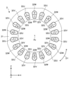
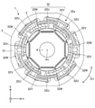
- FIG. 22 is a top view schematically showing the structure of the electric motor 1 according to the third embodiment.
- FIG. 23 is a cross-sectional view schematically showing the structure of the rotor 2 of the motor 1 shown in FIG. 22.
- a configuration different from the first and second embodiments will be described.
- the configuration not described in the present embodiment can be the same configuration as that of the first or second embodiment.
- the rotor 2 has 4 ⁇ n (n is an integer of 1 or more) magnetic poles.
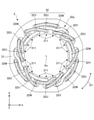
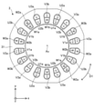
- FIG. 24 is a top view schematically showing the structure of the stator 3 of the motor 1 shown in FIG. 22.
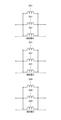
- FIG. 25 is a diagram showing the arrangement of the three-phase coil 32 in the slot 311 of the stator 3 shown in FIG. 24.
- FIG. 26 is a diagram schematically showing the arrangement of the three-phase coil 32 at the coil end 32a of the stator 3 and the arrangement of the three-phase coil 32 in the slot 311 shown in FIG. 24.
- the dashed line indicates the coil of each phase at the coil end 32a
- the chain line indicates the boundary between the inner layer and the outer layer in each slot 311.
- the stator 3 has a stator core 31 and a three-phase coil 32 attached to the stator core 31 in a distributed winding manner.
- the three-phase coil 32 (that is, the coil of each phase) has a coil side arranged in the slot 311 and a coil end 32a not arranged in the slot 311. Each coil end 32a is an end portion of the three-phase coil 32 in the axial direction.
- the 3-phase coil 32 has 3 ⁇ n U-phase coils 32U, 3 ⁇ n V-phase coils 32V, and 3 ⁇ n W-phase coils 32W at each coil end 32a (FIG. 22). That is, the three-phase coil 32 has three phases, a first phase, a second phase, and a third phase.
- the first phase is the U phase
- the second phase is the V phase
- the third phase is the W phase.
- each of the three phases is referred to as a U phase, a V phase, and a W phase.
- Each U-phase coil 32U, each V-phase coil 32V, and each W-phase coil 32W shown in FIG. 22 are also simply referred to as coils.
- n 2. Therefore, in the example shown in FIG. 22, at the coil end 32a, the three-phase coil 32 has six U-phase coils 32U, six V-phase coils 32V, and six W-phase coils 32W. However, the number of coils in each phase is not limited to six.
- the stator 3 has the structure shown in FIG. 3 at the two coil ends 32a. However, the stator 3 may have the structure shown in FIG. 22 at one of the two coil ends 32a.
- each of the 3 ⁇ n U-phase coils 32U, the 3 ⁇ n V-phase coils 32V, and the 3 ⁇ n W-phase coils 32W each includes a set of first to third coils. Includes n sets of coils. At each coil end 32a, n sets of coils are arranged at equal intervals in the circumferential direction of the stator 3. In each phase, one set of coils (also referred to as each coil group) is three coils arranged continuously in the circumferential direction. In other words, in each phase, a set of coils is three coils adjacent in the circumferential direction.
- the first to third coils constituting each coil group are arranged in this order in the circumferential direction of the stator 3.
- the first to third coils constituting each coil group are arranged in this order in the radial direction of the stator 3.
- At each coil end 32a at least two of the first to third coils of at least one phase are radially adjacent to each other.
- the first coil and the second coil of each phase are adjacent to each other in the radial direction, and the second coil and the third coil of each phase are radially adjacent to each other. Adjacent to each other.
- the region where the first to third coils of each of the n sets of coils are arranged is divided into an inner region, an intermediate region, and an outer region.
- the inner region is the region closest to the center of the stator core 31
- the outer region is the region farthest from the center of the stator core 31
- the intermediate region is the region between the inner region and the outer layer.
- the first coil is arranged inside the second coil in the radial direction
- the third coil is arranged outside the second coil in the radial direction.
- the second coil is arranged between the first coil and the third coil.
- each coil of the three-phase coil 32 is arranged in the slot 311 at a two-slot pitch on one end side of the stator core 31.
- the two-slot pitch means that one coil is arranged in the slot 311 every other slot. Therefore, as shown in FIGS. 22 and 24, each coil of the three-phase coil 32 is arranged in two slots 311 every other slot on one end side of the stator core 31. In other words, each coil of the three-phase coil 32 is arranged in two slots 311 with one slot 311 interposed therebetween on one end side of the stator core 31.
- the three U-phase coils 32U adjacent to each other in the circumferential direction at each coil end 32a are referred to as a first coil U1, a second coil U2, and a third coil U3, respectively.
- the three V-phase coils 32V adjacent to each other in the circumferential direction at each coil end 32a are referred to as a first coil V1, a second coil V2, and a third coil V3, respectively.
- the three W-phase coils 32W adjacent to each other in the circumferential direction at each coil end 32a are referred to as a first coil W1, a second coil W2, and a third coil W3, respectively.
- Each first coil U1, each second coil U2, each third coil U3, each first coil V1, each second coil V2, each third coil V3, each first coil W1, each The second coil W2 and each third coil W3 are also simply referred to as coils.
- the six U-phase coils 32U are a group of two coils in which the first to third coils U1, U2, and U3 adjacent to each other in the circumferential direction at each coil end 32a are a set. Contains Ug.
- the six U-phase coils 32U include two sets of coil groups Ug, and each coil group Ug of the six U-phase coils 32U is a first coil adjacent in the circumferential direction at each coil end 32a. Includes U1, a second coil U2, and a third coil U3.
- n sets of coil groups Ug out of 6 U-phase coils 32U are arranged at equal intervals in the circumferential direction of the stator 3.
- the first coil U1, the second coil U2, and the third coil U3 of each coil group Ug are arranged in this order in the circumferential direction of the stator 3.
- the first coil U1, the second coil U2, and the third coil U3 of each coil group Ug are arranged in this order in the radial direction of the stator 3. ing.
- the first coil U1, the second coil U2, and the third coil U3 of each coil group Ug are arranged from the inside of the stator core 31 in the radial direction of the stator 3. They are arranged in this order.
- the first coil U1, the second coil U2, and the third coil U3 of each coil group Ug are connected in series.
- the second coil U2 of each coil group Ug is wound around the stator core 31 in the direction opposite to the other two coils U1 and U3.
- a part of the first coil U1 and a part of the second coil U2 in each coil group Ug are arranged in one slot 311 out of 18 slots 311.
- the other part of the second coil U2 and the part of the third coil U3 in each coil group Ug are arranged in the other slot 311 out of the 18 slots 311. ..
- the other part of the first coil U1 in each coil group Ug is arranged in one slot 311 together with a part of the coils of the other phases.
- the other part of the third coil U3 of each coil group Ug is arranged in one slot 311 together with some of the coils of the other phase.
- a part of the first coil U1 is a first portion U1a of the first coil U1
- the other part of the first coil U1 is a first portion of the first coil U1.
- Part 2 U1b, part of the second coil U2 is the first part U2a of the second coil U2, and the other part of the second coil U2 is the second part of the second coil U2.
- a portion U2b, a portion of the third coil U3 is a first portion U3a of the third coil U3, and another portion of the third coil U3 is a second portion U3b of the third coil U3. Is.
- a part of the first coil U1 may be read as a second part U1b of the first coil U1, and the other part of the first coil U1 may be referred to as a first coil U1.
- the part U1a of 1 may be read
- a part of the second coil U2 may be read as the second part U2b of the second coil U2
- the other part of the second coil U2 may be read as the second part.
- It may be read as the first part U2a of the coil U2
- a part of the third coil U3 may be read as the second part U3b of the third coil U3, and another part of the third coil U3. May be read as the first portion U3a of the third coil U3.
- the six V-phase coils 32V are a group of two coils including the first to third coils V1, V2, and V3 adjacent to each other in the circumferential direction at each coil end 32a.
- the six V-phase coils 32V include two sets of coil groups Vg, and each coil group Vg of the six V-phase coils 32V is a first coil flankingly adjacent at each coil end 32a. Includes V1, a second coil V2, and a third coil V3.
- n sets of coil groups Vg out of 6 V-phase coils 32V are arranged at equal intervals in the circumferential direction of the stator 3.
- the first coil V1, the second coil V2, and the third coil V3 of each coil group Vg are arranged in this order in the circumferential direction of the stator 3.
- the first coil V1, the second coil V2, and the third coil V3 of each coil group Vg are arranged in this order in the radial direction of the stator 3. ing.
- the first coil V1, the second coil V2, and the third coil V3 of each coil group Vg are arranged from the inside of the stator core 31 in the radial direction of the stator 3. They are arranged in this order.
- the first coil V1, the second coil V2, and the third coil V3 of each coil group Vg are connected in series.
- the second coil V2 of each coil group Vg is wound around the stator core 31 in the direction opposite to the other two coils V1 and V3.
- a part of the first coil V1 and a part of the second coil V2 in each coil group Vg are arranged in one slot 311 out of 18 slots 311.
- the other part of the second coil V2 and the part of the third coil V3 in each coil group Vg are arranged in the other slot 311 out of the 18 slots 311. ..
- the other part of the first coil V1 in each coil group Vg is arranged in one slot 311 together with a part of the coils of the other phases.
- the other part of the third coil V3 of each coil group Vg is arranged in one slot 311 together with some of the coils of the other phase.
- a part of the first coil V1 is a first portion V1a of the first coil V1
- the other part of the first coil V1 is a first portion of the first coil V1.
- Part 2 V1b, part of the second coil V2 is the first part V2a of the second coil V2, and the other part of the second coil V2 is the second part of the second coil V2.
- Part V2b, part of the third coil V3 is the first part V3a of the third coil V3, and the other part of the third coil V3 is the second part V3b of the third coil V3. Is.
- a part of the first coil V1 may be read as a second part V1b of the first coil V1, and the other part of the first coil V1 may be referred to as a first coil V1.
- the part 1a may be read as the part V1a
- the part of the second coil V2 may be read as the second part V2b of the second coil V2
- the other part of the second coil V2 may be read as the second part.
- It may be read as the first part V2a of the coil V2
- a part of the third coil V3 may be read as the second part V3b of the third coil V3, and another part of the third coil V3. May be read as the first portion V3a of the third coil V3.
- the six W-phase coils 32W are a group of two coils in which the first to third coils W1, W2, and W3 adjacent to each other in the circumferential direction at each coil end 32a are a set. Contains Wg.
- the six W-phase coils 32W include two sets of coil groups Wg, and each coil group Wg of the six W-phase coils 32W is a first coil adjacent in the circumferential direction at each coil end 32a. Includes W1, a second coil W2, and a third coil W3.
- n sets of coil groups Wg out of 6 W-phase coils 32W are arranged at equal intervals in the circumferential direction of the stator 3.
- the first coil W1, the second coil W2, and the third coil W3 of each coil group Wg are arranged in this order in the circumferential direction of the stator 3.
- the first coil W1, the second coil W2, and the third coil W3 of each coil group Wg are arranged in this order in the radial direction of the stator 3. ing.
- the first coil W1, the second coil W2, and the third coil W3 of each coil group Wg are arranged from the inside of the stator core 31 in the radial direction of the stator 3. They are arranged in this order.
- the first coil W1, the second coil W2, and the third coil W3 of each coil group Wg are connected in series.
- the second coil W2 of each coil group Wg is wound around the stator core 31 in the direction opposite to the other two coils W1 and W3.
- a part of the first coil W1 and a part of the second coil W2 in each coil group Wg are arranged in one slot 311 out of 18 slots 311.
- the other part of the second coil W2 and the part of the third coil W3 in each coil group Wg are arranged in the other slot 311 out of the 18 slots 311. ..
- the other part of the first coil W1 in each coil group Wg is arranged in one slot 311 together with a part of the coils of the other phases.
- the other part of the third coil W3 in each coil group Wg is arranged in one slot 311 together with some of the coils of the other phase.
- a part of the first coil W1 is a first portion W1a of the first coil W1
- the other part of the first coil W1 is a first portion of the first coil W1.
- Part 2 W1b, part of the second coil W2 is the first part W2a of the second coil W2, and the other part of the second coil W2 is the second part of the second coil W2.
- a portion W2b, a portion of the third coil W3 is a first portion W3a of the third coil W3, and another portion of the third coil W3 is a second portion W3b of the third coil W3. Is.
- a part of the first coil W1 may be read as a second part W1b of the first coil W1, and the other part of the first coil W1 may be referred to as a first coil W1.
- the part W1a of 1 may be read
- a part of the second coil W2 may be read as the second part W2b of the second coil W2
- the other part of the second coil W2 may be read as the second part.
- It may be read as the first part W2a of the coil W2
- a part of the third coil W3 may be read as the second part W3b of the third coil W3, and another part of the third coil W3. May be read as the first portion W3a of the third coil W3.
- the first coil of the coil of each phase of the three-phase coil 32 is arranged in the inner layer of the slot 311.
- the second coil of each phase coil of the three-phase coil 32 is arranged in the inner layer or the outer layer of the slot 311.
- the third coil of each phase coil of the three-phase coil 32 is arranged in the outer layer of the slot 311.
- the coils of each phase are arranged in 6 outer layers and 6 inner layers.
- two coils adjacent to each other in the radial direction are arranged in the same slot 311.
- a portion of the first coil and a portion of the second coil are located in the same slot 311 (eg, first slot 311) and the other portion of the second coil and A part of the third coil is arranged in another slot (for example, the second slot 311).
- each second coil of the U-phase coil 32U is arranged in the outer layer of the slot 311 in which the first coil of the U-phase coil 32U is arranged.
- the other part of each second coil of the U-phase coil 32U is arranged in the inner layer of the slot 311 in which the third coil of the U-phase coil 32U is arranged.
- each third coil of the U-phase coil 32U is arranged in the outer layer of the slot 311 in which the second coil of the U-phase coil 32U is arranged.
- the other part of each third coil of the U-phase coil 32U is arranged in the outer layer of the slot 311 in which the first coil of the V-phase coil 32V is arranged. Therefore, the other part of each third coil of the U-phase coil 32U is arranged in the slot 311 outside the first coil of the V-phase coil 32V in the radial direction.
- V-phase coil 32V in slot 311 The arrangement of the V-phase coil 32V in the slot 311 will be specifically described below. A part of each first coil of the V-phase coil 32V is arranged in the inner layer of the slot 311 in which the second coil of the V-phase coil 32V is arranged. The other part of each first coil of the V-phase coil 32V is arranged in the inner layer of the slot 311 in which the third coil of the U-phase coil 32U is arranged. Therefore, the other part of each first coil of the V-phase coil 32V is arranged inside the third coil of the U-phase coil 32U in the radial direction in the slot 311.
- each second coil of the V-phase coil 32V is arranged in the outer layer of the slot 311 in which the first coil of the V-phase coil 32V is arranged.
- the other portion of each second coil of the V-phase coil 32V is located in the inner layer of slot 311 in which the third coil of the V-phase coil 32V is located.
- each third coil of the V-phase coil 32V is arranged in the outer layer of the slot 311 in which the second coil of the V-phase coil 32V is arranged.
- the other part of each third coil of the V-phase coil 32V is arranged in the outer layer of the slot 311 in which the first coil of the W-phase coil 32W is arranged. Therefore, the other part of each third coil of the V-phase coil 32V is arranged in the slot 311 outside the first coil of the W-phase coil 32W in the radial direction.
- each second coil of the W-phase coil 32W is arranged in the outer layer of the slot 311 in which the first coil of the W-phase coil 32W is arranged.
- the other part of each second coil of the W-phase coil 32W is arranged in the inner layer of the slot 311 in which the third coil of the W-phase coil 32W is arranged.
- each third coil of the W-phase coil 32W is arranged in the outer layer of the slot 311 in which the second coil of the W-phase coil 32W is arranged.
- the other part of each third coil of the W-phase coil 32W is arranged in the outer layer of the slot 311 in which the first coil of the U-phase coil 32U is arranged. Therefore, the other part of each third coil of the W-phase coil 32W is arranged in the slot 311 outside the first coil of the U-phase coil 32U in the radial direction.
- the third-order distributed winding coefficient kd can be obtained by the following equation.
- the third-order winding coefficient kw3 is obtained by the following equation.
- the third-order winding coefficient is 1, a circulating current due to the third-order harmonic component of the induced voltage may be generated in the three-phase coil, and the performance of the motor may deteriorate.
- ⁇ Volume winding coefficient of fundamental wave> on the other hand, in the motor 1 according to the present embodiment, two slots 311 correspond to one magnetic pole of the rotor 2, and each coil is arranged in the slot 311 at a pitch of two slots. Therefore, the short node winding coefficient kp of the fundamental wave of each coil can be obtained by the following equation.
- kp3 sin ⁇ 3 ⁇ P / (Q / S) ⁇ ⁇ ( ⁇ / 2)
- the third-order distributed winding coefficient kd can be obtained by the following equation.
- kd3 ⁇ sin (3 ⁇ ⁇ / 6) ⁇ / [q ⁇ sin ⁇ (3 ⁇ ⁇ / 6) / q ⁇ ]
- the motor 1 in the present embodiment has the advantages described in the first and second embodiments.
- the stator 3 since the stator 3 has the above-mentioned arrangement of the three-phase coil 32, the third-order winding coefficient is particularly reduced, and the deterioration of the performance of the motor 1 due to the circulating current is prevented. Can be done. As a result, as in the first embodiment, high motor efficiency can be obtained in both the low speed range (for example, intermediate conditions) and the high speed range (for example, rated conditions).
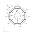
- FIG. 27 is a top view schematically showing the structure of the electric motor 1 according to the fourth embodiment.
- the fourth embodiment configurations different from the first, second, and third embodiments will be described.
- the configurations not described in the present embodiment can be the same configurations as those in the first, second, or third embodiments.
- the rotor 2 in the fourth embodiment is the same as the rotor 2 in the third embodiment.
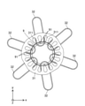
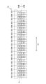
- FIG. 28 is a diagram schematically showing the arrangement of the three-phase coil 32 in the coil end 32a of the stator 3 of the motor 1 and the arrangement of the three-phase coil 32 in the slot 311 shown in FIG. 27.
- FIG. 28 is a developed view of the stator 3 shown in FIG. 27.
- the dashed line indicates the coil of each phase at the coil end 32a
- the chain line indicates the boundary between the inner layer and the outer layer in each slot 311.
- stator core 31 has 18 slots 311 as in the first embodiment.
- n sets of coils are arranged at equal intervals in the circumferential direction of the stator 3.
- the first to third coils constituting each coil group are arranged in this order in the circumferential direction of the stator 3 at a pitch of 2 slots.
- at each coil end 32a at least two of the first to third coils of at least one phase are radially adjacent to each other.
- the second coil and the third coil of each phase are adjacent to each other in the radial direction.
- the second coil of the first to third coils constituting each coil group is arranged outside the first coil and the third coil in the radial direction of the stator 3.
- One of the first coil and the third coil is closer to the center of the stator core 31 than the other. That is, at the coil end 32a of each phase, one of the first coil and the third coil is closer to the axis Ax than the other. Specifically, at the coil end 32a of each phase, the first coil is closer to the center of the stator core 31 than the third coil.
- the first coil is arranged in the inner region, the second coil is arranged in the outer region, and the third coil is arranged in the intermediate region.
- the first coil is arranged inside the second coil in the radial direction, and the second coil is arranged outside the third coil in the radial direction.
- the third coil is arranged between the first coil and the second coil.
- Each third coil is arranged between the first coil of the other adjacent phase and the second coil of the other phase.
- the third coil of the V phase is arranged between the first coil of the U phase and the second coil of the U phase. Therefore, at the coil end 32a of each coil group, the first coil is separated from the second coil.
- the first coil of each phase coil of the three-phase coil 32 is arranged in the inner layer of the slot 311.
- the second coil of each phase coil of the three-phase coil 32 is arranged in the outer layer of the slot 311.
- the third coil of each phase coil of the three-phase coil 32 is arranged in the inner layer or the outer layer of the slot 311.
- each first coil is arranged in the inner layer of slot 311 and each second coil is arranged in the outer layer of slot 311.
- a portion of each third coil is located in the inner layer of slot 311 and another portion of each third coil is located in the outer layer of the other slot 311.
- the coils of each phase are arranged at 6 places in the outer layer of the slot 311 and 6 places in the inner layer of the slot 311.
- each second coil of the U-phase coil 32U is arranged in the outer layer of the slot 311 in which the first coil of the U-phase coil 32U is arranged.
- the other part of each second coil of the U-phase coil 32U is arranged in the outer layer of the slot 311 in which the third coil of the U-phase coil 32U is arranged.
- each third coil of the U-phase coil 32U is arranged in the inner layer of the slot 311 in which the second coil of the U-phase coil 32U is arranged.
- the other part of each third coil of the U-phase coil 32U is arranged in the outer layer of the slot 311 in which the first coil of the V-phase coil 32V is arranged. Therefore, the other part of each third coil of the U-phase coil 32U is arranged in the slot 311 outside the first coil of the V-phase coil 32V in the radial direction.
- V-phase coil 32V in slot 311 The arrangement of the V-phase coil 32V in the slot 311 will be specifically described below. A part of each first coil of the V-phase coil 32V is arranged in the inner layer of the slot 311 in which the second coil of the V-phase coil 32V is arranged. The other part of each first coil of the V-phase coil 32V is arranged in the inner layer of the slot 311 in which the third coil of the U-phase coil 32U is arranged. Therefore, the other part of each first coil of the V-phase coil 32V is arranged inside the third coil of the U-phase coil 32U in the radial direction in the slot 311.
- each second coil of the V-phase coil 32V is arranged in the outer layer of the slot 311 in which the first coil of the V-phase coil 32V is arranged.
- the other part of each second coil of the V-phase coil 32V is arranged in the outer layer of the slot 311 in which the third coil of the V-phase coil 32V is arranged.
- each third coil of the V-phase coil 32V is arranged in the inner layer of the slot 311 in which the second coil of the V-phase coil 32V is arranged.
- the other part of each third coil of the V-phase coil 32V is arranged in the outer layer of the slot 311 in which the first coil of the W-phase coil 32W is arranged. Therefore, the other part of each third coil of the V-phase coil 32V is arranged in the slot 311 outside the first coil of the W-phase coil 32W in the radial direction.
- each second coil of the W-phase coil 32W is arranged in the outer layer of the slot 311 in which the first coil of the W-phase coil 32W is arranged.
- the other part of each second coil of the W-phase coil 32W is arranged in the outer layer of the slot 311 in which the third coil of the W-phase coil 32W is arranged.
- each third coil of the W-phase coil 32W is arranged in the inner layer of the slot 311 in which the second coil of the W-phase coil 32W is arranged.
- the other part of each third coil of the W-phase coil 32W is arranged in the outer layer of the slot 311 in which the first coil of the U-phase coil 32U is arranged. Therefore, the other part of each third coil of the W-phase coil 32W is arranged in the slot 311 outside the first coil of the U-phase coil 32U in the radial direction.
- the electric motor 1 in the present embodiment has the advantages described in the first to third embodiments.
- FIG. 29 is a cross-sectional view schematically showing the structure of the compressor 300.
- the compressor 300 has a motor 1 as an electric element, a closed container 307 as a housing, and a compression mechanism 305 as a compression element (also referred to as a compression device).
- the compressor 300 is a scroll compressor.
- the compressor 300 is not limited to the scroll compressor.
- the compressor 300 may be a compressor other than the scroll compressor, for example, a rotary compressor.
- the electric motor 1 in the compressor 300 is the electric motor 1 described in the first embodiment.
- the electric motor 1 drives the compression mechanism 305.
- the compressor 300 further includes a subframe 308 that supports the lower end of the shaft 4 (that is, the end opposite to the compression mechanism 305 side).
- the compression mechanism 305 is arranged in the closed container 307.
- the compression mechanism 305 has a fixed scroll 301 having a spiral portion, a swing scroll 302 having a spiral portion forming a compression chamber between the spiral portion of the fixed scroll 301, and a compliance frame 303 holding the upper end portion of the shaft 4. And a guide frame 304 fixed to the closed container 307 and holding the compliance frame 303.
- a suction pipe 310 penetrating the closed container 307 is press-fitted into the fixed scroll 301. Further, the closed container 307 is provided with a discharge pipe 306 for discharging the high-pressure refrigerant gas discharged from the fixed scroll 301 to the outside.
- the discharge pipe 306 communicates with an opening provided between the compression mechanism 305 of the closed container 307 and the electric motor 1.
- the motor 1 is fixed to the closed container 307 by fitting the stator 3 into the closed container 307.
- the configuration of the electric motor 1 is as described above.
- a glass terminal 309 for supplying electric power to the electric motor 1 is fixed to the closed container 307 by welding.
- the compressor 300 Since the compressor 300 has the electric motor 1 described in the first to fourth embodiments, the compressor 300 has the advantages described in the first embodiment.
- the compressor 300 has the electric motor 1 described in the first to fourth embodiments, the performance of the compressor 300 can be improved.
- FIG. 30 is a diagram schematically showing the configuration of the refrigerating and air-conditioning apparatus 7 according to the sixth embodiment.
- the refrigerating and air-conditioning device 7 can be operated for heating and cooling, for example.
- the refrigerant circuit diagram shown in FIG. 30 is an example of a refrigerant circuit diagram of an air conditioner capable of cooling operation.
- the refrigerating and air-conditioning device 7 has an outdoor unit 71, an indoor unit 72, and a refrigerant pipe 73 connecting the outdoor unit 71 and the indoor unit 72.
- the outdoor unit 71 has a compressor 300, a condenser 74 as a heat exchanger, a throttle device 75, and an outdoor blower 76 (first blower).
- the condenser 74 condenses the refrigerant compressed by the compressor 300.
- the throttle device 75 decompresses the refrigerant condensed by the condenser 74 and adjusts the flow rate of the refrigerant.
- the diaphragm device 75 is also referred to as a decompression device.
- the indoor unit 72 has an evaporator 77 as a heat exchanger and an indoor blower 78 (second blower).
- the evaporator 77 evaporates the refrigerant decompressed by the throttle device 75 to cool the indoor air.
- the refrigerant is compressed by the compressor 300 and flows into the condenser 74.
- the refrigerant is condensed by the condenser 74, and the condensed refrigerant flows into the throttle device 75.
- the refrigerant is decompressed by the throttle device 75, and the decompressed refrigerant flows into the evaporator 77.
- the refrigerant evaporates in the evaporator 77, and the refrigerant (specifically, the refrigerant gas) flows into the compressor 300 of the outdoor unit 71 again.
- the configuration and operation of the refrigerating and air-conditioning apparatus 7 described above is an example, and is not limited to the above-mentioned example.
- the refrigerating and air-conditioning apparatus 7 since the electric motor 1 described in the first to fourth embodiments is provided, the refrigerating and air-conditioning apparatus 7 has an advantage corresponding to one of the first to four embodiments. have.
- the refrigerating and air-conditioning apparatus 7 according to the sixth embodiment has the compressor 300 according to the fifth embodiment, the performance of the refrigerating and air-conditioning apparatus 7 can be improved.
Abstract
An electric motor (1) comprises a rotor (2), a stator (3), and a connection switching unit (60). The stator (3) has a stator core (31) which has 6×n (n is an integer of 1 or more) slots (311) and a three-phase coil (32) which forms 2×n magnetic poles. The connection switching unit (60) switches the connection state of the three-phase coil (32) between a first connection state and a second connection state. The three-phase coil (32) has, at a coil end (32a), 2×n U-phase coils (32U), 2×n V-phase coils (32V), and 2×n W-phase coils (32W). Each coil of the three-phase coil (32) is, at one end side of the stator core (31), disposed in two slots (311) at one-slot intervals.
Description
本開示は、電動機に関する。
This disclosure relates to motors.
一般に、固定子鉄心に分布巻きで取り付けられた3相コイルを備えた電動機が用いられている(例えば、特許文献1)。3相コイルを備えた電動機では、3相コイルを形成する巻線(固定子巻線とも称する)の巻き数が多い場合、少ない電流(電動機電流とも称する)で電動機を駆動させることができ、インバータ損失を低減することができる。その結果、電動機の効率(電動機効率とも称する)を高めることができる。しかしながら、巻線の巻き数が多い場合、3相コイルにおける誘起電圧が上昇し、電動機の回転速度を上げることができないことがある。一方、巻線の巻き数が少ない場合、3相コイルにおける誘起電圧を低減することができ、電動機の回転速度を上げることができる。
Generally, a motor equipped with a three-phase coil attached to a stator core by distributed winding is used (for example, Patent Document 1). In a motor equipped with a 3-phase coil, when the number of windings forming the 3-phase coil (also referred to as stator winding) is large, the motor can be driven with a small current (also referred to as motor current), and an inverter. The loss can be reduced. As a result, the efficiency of the motor (also referred to as motor efficiency) can be increased. However, when the number of turns of the winding is large, the induced voltage in the three-phase coil rises, and the rotation speed of the motor may not be increased. On the other hand, when the number of turns of the winding is small, the induced voltage in the three-phase coil can be reduced, and the rotation speed of the motor can be increased.
しかしながら、従来の技術では、電動機の回転速度を上げた場合、3相コイルの接続状態によっては、3相コイルにおいて誘起電圧の3次高調波成分による循環電流が発生し、電動機の性能が低下することがある。その結果、電動機の効率が低下するという問題がある。
However, in the conventional technique, when the rotation speed of the motor is increased, a circulating current is generated in the three-phase coil due to the third harmonic component of the induced voltage depending on the connection state of the three-phase coil, and the performance of the motor deteriorates. Sometimes. As a result, there is a problem that the efficiency of the electric motor is lowered.
本開示の目的は、電動機の効率を高めることである。
The purpose of this disclosure is to improve the efficiency of the motor.
本開示の一態様に係る電動機は、
6×n個(nは1以上の整数)のスロットを有する固定子鉄心と、前記固定子鉄心に分布巻きで取り付けられており、2×n個の磁極を形成する3相コイルとを有する固定子と、
永久磁石を有し、前記固定子の内側に配置された回転子と、
前記3相コイルの結線状態を第1の結線状態と前記第1の結線状態とは異なる第2の結線状態との間で切り替える結線切り替え部と
を備え、
前記3相コイルは、前記3相コイルのコイルエンドにおいて2×n個のU相コイル、2×n個のV相コイル、及び2×n個のW相コイルを有し、
前記3相コイルの各コイルは、前記固定子鉄心の一端側において1スロットおきに前記6×n個のスロットのうちの2つのスロットに配置されている。
本開示の他の態様に係る電動機は、
9×n個(nは1以上の整数)のスロットを有する固定子鉄心と、前記固定子鉄心に分布巻きで取り付けられており、4×n個の磁極を形成する3相コイルとを有する固定子と、
永久磁石を有し、前記固定子の内側に配置された回転子と、
前記3相コイルの結線状態を第1の結線状態と前記第1の結線状態とは異なる第2の結線状態との間で切り替える結線切り替え部と
を備え、
前記3相コイルは、前記3相コイルのコイルエンドにおいて3×n個のU相コイル、3×n個のV相コイル、及び3×n個のW相コイルを有し、
前記3相コイルの各コイルは、前記固定子鉄心の一端側において1スロットおきに前記9×n個のスロットのうちの2つのスロットに配置されている。
本開示の他の態様に係る駆動装置は、
前記電動機と、
前記結線切り替え部を制御する制御装置と
を備える。
本開示の他の態様に係る圧縮機は、
密閉容器と、
前記密閉容器内に配置された圧縮装置と、
前記圧縮装置を駆動する前記電動機と
を備える。
本開示の他の態様に係る空気調和機は、
前記圧縮機と、
熱交換器と
を備える。 The motor according to one aspect of the present disclosure is
A stator core having 6 × n (n is an integer of 1 or more) slots and a three-phase coil attached to the stator core by distributed winding and forming 2 × n magnetic poles. With the child
A rotor having a permanent magnet and placed inside the stator,
A connection switching unit for switching the connection state of the three-phase coil between a first connection state and a second connection state different from the first connection state is provided.
The three-phase coil has 2 × n U-phase coils, 2 × n V-phase coils, and 2 × n W-phase coils at the coil end of the 3-phase coil.
Each coil of the three-phase coil is arranged in two of the 6 × n slots every other slot on one end side of the stator core.
The motor according to another aspect of the present disclosure is
A stator core having 9 × n (n is an integer of 1 or more) slots and a three-phase coil attached to the stator core by distributed winding and forming 4 × n magnetic poles. With the child
A rotor having a permanent magnet and placed inside the stator,
A connection switching unit for switching the connection state of the three-phase coil between a first connection state and a second connection state different from the first connection state is provided.
The three-phase coil has 3 × n U-phase coils, 3 × n V-phase coils, and 3 × n W-phase coils at the coil end of the 3-phase coil.
Each coil of the three-phase coil is arranged in two of the 9 × n slots every other slot on one end side of the stator core.
The drive device according to another aspect of the present disclosure is
With the motor
A control device for controlling the connection switching unit is provided.
The compressor according to another aspect of the present disclosure is
With a closed container
With the compression device arranged in the closed container,
The electric motor for driving the compression device is provided.
The air conditioner according to another aspect of the present disclosure is
With the compressor
Equipped with a heat exchanger.
本開示によれば、電動機の効率を高めることができる。
According to this disclosure, the efficiency of the motor can be improved.
実施の形態1.
各図に示されるxyz直交座標系において、z軸方向(z軸)は、電動機1の軸線Axと平行な方向を示し、x軸方向(x軸)は、z軸方向(z軸)に直交する方向を示し、y軸方向(y軸)は、z軸方向及びx軸方向の両方に直交する方向を示す。軸線Axは、固定子3の中心であり、回転子2の回転中心でもある。軸線Axと平行な方向は、「回転子2の軸方向」又は単に「軸方向」ともいう。径方向は、回転子2又は固定子3の半径方向であり、軸線Axと直交する方向である。xy平面は、軸方向と直交する平面である。矢印D1は、軸線Axを中心とする周方向を示す。回転子2又は固定子3の周方向を、単に「周方向」ともいう。Embodiment 1.
In the xyz Cartesian coordinate system shown in each figure, the z-axis direction (z-axis) indicates a direction parallel to the axis Ax of theelectric motor 1, and the x-axis direction (x-axis) is orthogonal to the z-axis direction (z-axis). The y-axis direction (y-axis) indicates a direction orthogonal to both the z-axis direction and the x-axis direction. The axis Ax is the center of the stator 3 and the center of rotation of the rotor 2. The direction parallel to the axis Ax is also referred to as "axial direction of rotor 2" or simply "axial direction". The radial direction is the radial direction of the rotor 2 or the stator 3, and is a direction orthogonal to the axis Ax. The xy plane is a plane orthogonal to the axial direction. The arrow D1 indicates the circumferential direction about the axis Ax. The circumferential direction of the rotor 2 or the stator 3 is also simply referred to as "circumferential direction".
各図に示されるxyz直交座標系において、z軸方向(z軸)は、電動機1の軸線Axと平行な方向を示し、x軸方向(x軸)は、z軸方向(z軸)に直交する方向を示し、y軸方向(y軸)は、z軸方向及びx軸方向の両方に直交する方向を示す。軸線Axは、固定子3の中心であり、回転子2の回転中心でもある。軸線Axと平行な方向は、「回転子2の軸方向」又は単に「軸方向」ともいう。径方向は、回転子2又は固定子3の半径方向であり、軸線Axと直交する方向である。xy平面は、軸方向と直交する平面である。矢印D1は、軸線Axを中心とする周方向を示す。回転子2又は固定子3の周方向を、単に「周方向」ともいう。
In the xyz Cartesian coordinate system shown in each figure, the z-axis direction (z-axis) indicates a direction parallel to the axis Ax of the
〈電動機1〉
図1は、実施の形態1に係る電動機1の構造を概略的に示す上面図である。 <Motor 1>
FIG. 1 is a top view schematically showing the structure of themotor 1 according to the first embodiment.
図1は、実施の形態1に係る電動機1の構造を概略的に示す上面図である。 <
FIG. 1 is a top view schematically showing the structure of the
電動機1は、複数の磁極を持つ回転子2と、固定子3と、回転子2に固定されたシャフト4とを有する。電動機1は、例えば、永久磁石同期電動機である。
The motor 1 has a rotor 2 having a plurality of magnetic poles, a stator 3, and a shaft 4 fixed to the rotor 2. The electric motor 1 is, for example, a permanent magnet synchronous motor.
回転子2は、固定子3の内側に回転可能に配置されている。回転子2と固定子3との間には、エアギャップが存在する。回転子2は、軸線Axを中心として回転する。
The rotor 2 is rotatably arranged inside the stator 3. There is an air gap between the rotor 2 and the stator 3. The rotor 2 rotates about the axis Ax.
図2は、回転子2の構造を概略的に示す断面図である。
回転子2は、回転子鉄心21と、少なくとも1つの永久磁石22とを有する。回転子2は、2×n個(nは1以上の整数)の磁極を持つ。 FIG. 2 is a cross-sectional view schematically showing the structure of therotor 2.
Therotor 2 has a rotor core 21 and at least one permanent magnet 22. The rotor 2 has 2 × n (n is an integer of 1 or more) magnetic poles.
回転子2は、回転子鉄心21と、少なくとも1つの永久磁石22とを有する。回転子2は、2×n個(nは1以上の整数)の磁極を持つ。 FIG. 2 is a cross-sectional view schematically showing the structure of the
The
回転子鉄心21は、複数の磁石挿入孔211と、シャフト4が配置されるシャフト孔212とを有する。回転子鉄心21は、各磁石挿入孔211に連通する空間である少なくとも1つのフラックスバリア部をさらに有してもよい。
The rotor core 21 has a plurality of magnet insertion holes 211 and a shaft hole 212 in which the shaft 4 is arranged. The rotor core 21 may further have at least one flux barrier portion that is a space communicating with each magnet insertion hole 211.
本実施の形態では、回転子2は、複数の永久磁石22を有する。各永久磁石22は、各磁石挿入孔211内に配置されている。
In the present embodiment, the rotor 2 has a plurality of permanent magnets 22. Each permanent magnet 22 is arranged in each magnet insertion hole 211.
1つの永久磁石22が、回転子2の1磁極、すなわち、N極又はS極を形成する。ただし、2以上の永久磁石22が回転子2の1磁極を形成してもよい。
One permanent magnet 22 forms one magnetic pole of the rotor 2, that is, an N pole or an S pole. However, two or more permanent magnets 22 may form one magnetic pole of the rotor 2.
本実施の形態では、xy平面において、回転子2の1磁極を形成する1つの永久磁石22は、真っ直ぐに配置されている。ただし、xy平面において、回転子2の1磁極を形成する1組の永久磁石22が、V字形状を持つように配置されていてもよい。
In the present embodiment, one permanent magnet 22 forming one magnetic pole of the rotor 2 is arranged straight in the xy plane. However, in the xy plane, a set of permanent magnets 22 forming one magnetic pole of the rotor 2 may be arranged so as to have a V shape.
回転子2の各磁極の中心は、回転子2の各磁極(すなわち、回転子2のN極又はS極)の中心に位置する。回転子2の各磁極(単に「各磁極」又は「磁極」とも称する)とは、回転子2のN極又はS極の役目をする領域を意味する。
The center of each magnetic pole of the rotor 2 is located at the center of each magnetic pole of the rotor 2 (that is, the north pole or the south pole of the rotor 2). Each magnetic pole of the rotor 2 (also simply referred to as "each magnetic pole" or "magnetic pole") means a region serving as an N pole or an S pole of the rotor 2.
〈固定子3〉
図3は、固定子3の構造を概略的に示す上面図である。
図4は、スロット311内の3相コイル32の配置を示す図である。
図5は、コイルエンド32aにおける3相コイル32の配置及びスロット311内の3相コイル32の配置を模式的に示す図である。図5において、破線は、コイルエンド32aにおける各相のコイルを示し、鎖線は、各スロット311内の内層と外層との間の境界を示す。
図3に示されるように、固定子3は、固定子鉄心31と、固定子鉄心31に分布巻きで取り付けられた3相コイル32とを有する。 <Stator 3>
FIG. 3 is a top view schematically showing the structure of thestator 3.
FIG. 4 is a diagram showing the arrangement of the three-phase coil 32 in the slot 311.
FIG. 5 is a diagram schematically showing the arrangement of the three-phase coil 32 at the coil end 32a and the arrangement of the three-phase coil 32 in the slot 311. In FIG. 5, the dashed line indicates the coil of each phase at the coil end 32a, and the chain line indicates the boundary between the inner layer and the outer layer in each slot 311.
As shown in FIG. 3, thestator 3 has a stator core 31 and a three-phase coil 32 attached to the stator core 31 in a distributed winding manner.
図3は、固定子3の構造を概略的に示す上面図である。
図4は、スロット311内の3相コイル32の配置を示す図である。
図5は、コイルエンド32aにおける3相コイル32の配置及びスロット311内の3相コイル32の配置を模式的に示す図である。図5において、破線は、コイルエンド32aにおける各相のコイルを示し、鎖線は、各スロット311内の内層と外層との間の境界を示す。
図3に示されるように、固定子3は、固定子鉄心31と、固定子鉄心31に分布巻きで取り付けられた3相コイル32とを有する。 <
FIG. 3 is a top view schematically showing the structure of the
FIG. 4 is a diagram showing the arrangement of the three-
FIG. 5 is a diagram schematically showing the arrangement of the three-
As shown in FIG. 3, the
固定子鉄心31は、環状のヨークと、ヨークから径方向に延在する複数のティースと、3相コイル32が配置される6×n個(nは1以上の整数)のスロット311とを有する。各スロット311を、例えば、第1のスロット、第2のスロット、・・・、第Nのスロットとも称する。図4及び図5に示されるように、6×n個のスロット311の各々は、3相コイル32のうちの1つのコイルが配置される内層と、径方向における内層の外側に設けられており3相コイル32のうちの1つのコイルが配置される外層とを含む。すなわち、図4及び図5に示される例では、各スロット311内の空間は、内層及び外層に分けられている。本実施の形態では、n=3である。したがって、図3から図5に示される例では、固定子鉄心31は、18個のスロット311を有する。
The stator core 31 has an annular yoke, a plurality of teeth extending radially from the yoke, and 6 × n (n is an integer of 1 or more) slots 311 in which the three-phase coil 32 is arranged. .. Each slot 311 is also referred to as, for example, a first slot, a second slot, ..., Nth slot. As shown in FIGS. 4 and 5, each of the 6 × n slots 311 is provided on the inner layer in which one of the three-phase coils 32 is arranged and on the outer side of the inner layer in the radial direction. Includes an outer layer in which one of the three-phase coils 32 is located. That is, in the example shown in FIGS. 4 and 5, the space in each slot 311 is divided into an inner layer and an outer layer. In this embodiment, n = 3. Therefore, in the example shown in FIGS. 3 to 5, the stator core 31 has 18 slots 311.
3相コイル32(すなわち、各相のコイル)は、スロット311内に配置されたコイルサイドと、スロット311内に配置されていないコイルエンド32aとを持つ。各コイルエンド32aは、軸方向における3相コイル32の端部である。
The three-phase coil 32 (that is, the coil of each phase) has a coil side arranged in the slot 311 and a coil end 32a not arranged in the slot 311. Each coil end 32a is an end portion of the three-phase coil 32 in the axial direction.
3相コイル32は、各コイルエンド32aにおいて、2×n個のU相コイル32U、2×n個のV相コイル32V、及び2×n個のW相コイル32Wを有する。言い換えると、3相コイル32は、固定子鉄心31上において、2×n個のU相コイル32U、2×n個のV相コイル32V、及び2×n個のW相コイル32Wを有する。すなわち、3相コイル32は、第1相、第2相、及び第3相の3相を持つ。例えば、第1相はU相であり、第2相はV相であり、第3相はW相である。本実施の形態では、3相の各々を、U相、V相、及びW相と称する。図1及び図3に示される各U相コイル32U、各V相コイル32V、及び各W相コイル32Wを、単にコイルとも称する。
The 3-phase coil 32 has 2 × n U-phase coils 32U, 2 × n V- phase coils 32V, and 2 × n W-phase coils 32W at each coil end 32a. In other words, the three-phase coil 32 has 2 × n U-phase coils 32U, 2 × n V- phase coils 32V, and 2 × n W-phase coils 32W on the stator core 31. That is, the three-phase coil 32 has three phases, a first phase, a second phase, and a third phase. For example, the first phase is the U phase, the second phase is the V phase, and the third phase is the W phase. In this embodiment, each of the three phases is referred to as a U phase, a V phase, and a W phase. Each U-phase coil 32U, each V-phase coil 32V, and each W-phase coil 32W shown in FIGS. 1 and 3 are also simply referred to as coils.
本実施の形態では、n=3である。したがって、図1及び図3に示される例では、コイルエンド32aにおいて、3相コイル32は、6個のU相コイル32U、6個のV相コイル32V、及び6個のW相コイル32Wを持っている。ただし、各相のコイルの数は、6個に限定されない。本実施の形態では、固定子3は、2つのコイルエンド32aにおいて、図3に示される構造を持っている。ただし、固定子3は、2つのコイルエンド32aの一方において、図3に示される構造を持っていればよい。
In this embodiment, n = 3. Therefore, in the example shown in FIGS. 1 and 3, at the coil end 32a, the three-phase coil 32 has six U-phase coils 32U, six V-phase coils 32V, and six W-phase coils 32W. ing. However, the number of coils in each phase is not limited to six. In this embodiment, the stator 3 has the structure shown in FIG. 3 at the two coil ends 32a. However, the stator 3 may have the structure shown in FIG. 3 at one of the two coil ends 32a.
3相コイル32に電流が流れたとき、3相コイル32は、2×n個の磁極を形成する。本実施の形態では、n=3である。したがって、本実施の形態では、3相コイル32に電流が流れたとき、3相コイル32は、6磁極を形成する。
When a current flows through the three-phase coil 32, the three-phase coil 32 forms 2 × n magnetic poles. In this embodiment, n = 3. Therefore, in the present embodiment, when a current flows through the three-phase coil 32, the three-phase coil 32 forms six magnetic poles.
図1及び図3に示されるように、3相コイル32の各コイルは、固定子鉄心31の一端側において、2スロットピッチでスロット311内に配置されている。2スロットピッチとは、「2スロット毎」を意味する。すなわち、2スロットピッチとは、1つのコイルが2スロット毎にスロット311に配置されることを意味する。言い換えると、2スロットピッチとは、1つのコイルが1スロットおきにスロット311に配置されることを意味する。したがって、図1及び図3に示されるように、3相コイル32の各コイルは、固定子鉄心31の一端側において、1スロットおきに2つのスロット311に配置されている。言い換えると、3相コイル32の各コイルは、固定子鉄心31の一端側において、1つのスロット311をはさんで2つのスロット311に配置されている。
As shown in FIGS. 1 and 3, each coil of the three-phase coil 32 is arranged in the slot 311 at a two-slot pitch on one end side of the stator core 31. The 2-slot pitch means "every 2 slots". That is, the two-slot pitch means that one coil is arranged in the slot 311 every two slots. In other words, the two-slot pitch means that one coil is arranged in the slot 311 every other slot. Therefore, as shown in FIGS. 1 and 3, each coil of the three-phase coil 32 is arranged in two slots 311 every other slot on one end side of the stator core 31. In other words, each coil of the three-phase coil 32 is arranged in two slots 311 with one slot 311 interposed therebetween on one end side of the stator core 31.
図4及び図5に示されるように、各スロット311には、2つのコイルが配置されている。各コイルは、他の相のコイルと共に各スロット311に配置されている。すなわち、各スロット311には、異なる相の2つのコイルが配置されている。各相のコイルは、6箇所の内層及び6箇所の外層に配置されている。
As shown in FIGS. 4 and 5, two coils are arranged in each slot 311. Each coil is arranged in each slot 311 along with the coils of the other phases. That is, two coils having different phases are arranged in each slot 311. The coils of each phase are arranged in 6 inner layers and 6 outer layers.
〈スロット311内のU相コイル32Uの配置〉
スロット311内のU相コイル32Uの配置を以下に具体的に説明する。
2×n個のU相コイル32Uのうちのn個のU相コイル32Uは、スロット311の外層に配置されている。2×n個のU相コイル32Uのうちの他のn個のU相コイル32Uは、スロット311の内層に配置されている。図1に示される例では、3個のU相コイル32Uがスロット311の外層に配置されており、他の3個のU相コイル32Uがスロット311の内層に配置されている。 <Arrangement ofU-phase coil 32U in slot 311>
The arrangement of theU-phase coil 32U in the slot 311 will be specifically described below.
Of the 2 × n U-phase coils 32U, n U-phase coils 32U are arranged in the outer layer ofslot 311. The other n U-phase coils 32U of the 2 × n U-phase coils 32U are arranged in the inner layer of the slot 311. In the example shown in FIG. 1, three U-phase coils 32U are arranged in the outer layer of slot 311 and the other three U-phase coils 32U are arranged in the inner layer of slot 311.
スロット311内のU相コイル32Uの配置を以下に具体的に説明する。
2×n個のU相コイル32Uのうちのn個のU相コイル32Uは、スロット311の外層に配置されている。2×n個のU相コイル32Uのうちの他のn個のU相コイル32Uは、スロット311の内層に配置されている。図1に示される例では、3個のU相コイル32Uがスロット311の外層に配置されており、他の3個のU相コイル32Uがスロット311の内層に配置されている。 <Arrangement of
The arrangement of the
Of the 2 × n U-phase coils 32U, n U-phase coils 32U are arranged in the outer layer of
〈スロット311内のV相コイル32Vの配置〉
スロット311内のV相コイル32Vの配置を以下に具体的に説明する。
V相コイル32Vの一部は、U相コイル32Uが配置されたスロット311の内層に配置されている。V相コイル32Vの他の一部は、W相コイル32Wが配置されたスロット311の外層に配置されている。すなわち、各V相コイル32Vの一部が他の相のコイルが配置されたスロット311の外層に配置されている場合、各V相コイル32Vの他の一部は、他の相のコイルが配置されたスロット311の内層に配置されている。各V相コイル32Vの一部が他の相のコイルが配置されたスロット311の内層に配置されている場合、各V相コイル32Vの他の一部は、他の相のコイルが配置されたスロット311の外層に配置されている。 <Arrangement of V-phase coil 32V in slot 311>
The arrangement of the V-phase coil 32V in the slot 311 will be specifically described below.
A part of the V-phase coil 32V is arranged in the inner layer of the slot 311 in which the U-phase coil 32U is arranged. The other part of the V-phase coil 32V is arranged in the outer layer of the slot 311 in which the W-phase coil 32W is arranged. That is, when a part of each V-phase coil 32V is arranged in the outer layer of the slot 311 in which the coil of the other phase is arranged, the other part of each V-phase coil 32V is arranged with the coil of the other phase. It is arranged in the inner layer of the slot 311. When a part of each V-phase coil 32V is arranged in the inner layer of the slot 311 in which the coil of the other phase is arranged, the other part of each V-phase coil 32V is arranged in the coil of the other phase. It is arranged on the outer layer of slot 311.
スロット311内のV相コイル32Vの配置を以下に具体的に説明する。
V相コイル32Vの一部は、U相コイル32Uが配置されたスロット311の内層に配置されている。V相コイル32Vの他の一部は、W相コイル32Wが配置されたスロット311の外層に配置されている。すなわち、各V相コイル32Vの一部が他の相のコイルが配置されたスロット311の外層に配置されている場合、各V相コイル32Vの他の一部は、他の相のコイルが配置されたスロット311の内層に配置されている。各V相コイル32Vの一部が他の相のコイルが配置されたスロット311の内層に配置されている場合、各V相コイル32Vの他の一部は、他の相のコイルが配置されたスロット311の外層に配置されている。 <Arrangement of V-
The arrangement of the V-
A part of the V-
〈スロット311内のW相コイル32Wの配置〉
スロット311内のW相コイル32Wの配置を以下に具体的に説明する。
2×n個のW相コイル32Wのうちのn個のW相コイル32Wは、スロット311の外層に配置されている。2×n個のW相コイル32Wのうちの他のn個のW相コイル32Wは、スロット311の内層に配置されている。図1に示される例では、3個のW相コイル32Wがスロット311の外層に配置されており、他の3個のW相コイル32Wがスロット311の内層に配置されている。 <Arrangement ofW phase coil 32W in slot 311>
The arrangement of the W-phase coil 32W in the slot 311 will be specifically described below.
Of the 2 × n W-phase coils 32W, n W-phase coils 32W are arranged in the outer layer of the slot 311. The other n W-phase coils 32W out of the 2 × n W-phase coils 32W are arranged in the inner layer of the slot 311. In the example shown in FIG. 1, three W-phase coils 32W are arranged in the outer layer of slot 311 and the other three W-phase coils 32W are arranged in the inner layer of slot 311.
スロット311内のW相コイル32Wの配置を以下に具体的に説明する。
2×n個のW相コイル32Wのうちのn個のW相コイル32Wは、スロット311の外層に配置されている。2×n個のW相コイル32Wのうちの他のn個のW相コイル32Wは、スロット311の内層に配置されている。図1に示される例では、3個のW相コイル32Wがスロット311の外層に配置されており、他の3個のW相コイル32Wがスロット311の内層に配置されている。 <Arrangement of
The arrangement of the W-
Of the 2 × n W-
〈コイルエンド32aにおける3相コイル32の配置〉
スロット311の外層に配置されたn個のU相コイル32Uは、周方向に等間隔に配置されている。スロット311の内層に配置されたn個のU相コイル32Uは、周方向に等間隔に配置されている。2×n個のV相コイル32Vは、周方向に等間隔に配置されている。スロット311の外層に配置されたn個のW相コイル32Wは、周方向に等間隔に配置されている。スロット311の内層に配置されたn個のW相コイル32Wは、周方向に等間隔に配置されている。 <Arrangement of 3-phase coil 32 at coil end 32a>
The n U-phase coils 32U arranged in the outer layer of theslot 311 are arranged at equal intervals in the circumferential direction. The n U-phase coils 32U arranged in the inner layer of the slot 311 are arranged at equal intervals in the circumferential direction. The 2 × n V-phase coils 32V are arranged at equal intervals in the circumferential direction. The n W-phase coils 32W arranged in the outer layer of the slot 311 are arranged at equal intervals in the circumferential direction. The n W-phase coils 32W arranged in the inner layer of the slot 311 are arranged at equal intervals in the circumferential direction.
スロット311の外層に配置されたn個のU相コイル32Uは、周方向に等間隔に配置されている。スロット311の内層に配置されたn個のU相コイル32Uは、周方向に等間隔に配置されている。2×n個のV相コイル32Vは、周方向に等間隔に配置されている。スロット311の外層に配置されたn個のW相コイル32Wは、周方向に等間隔に配置されている。スロット311の内層に配置されたn個のW相コイル32Wは、周方向に等間隔に配置されている。 <Arrangement of 3-
The n U-phase coils 32U arranged in the outer layer of the
〈基本波の巻線係数〉
本実施の形態に係る電動機1では、回転子2の1磁極に対して3つのスロット311が対応しており、各コイルは、2スロットピッチでスロット311に配置されている。したがって、各コイルの基本波の短節巻係数kpは、以下の式で求められる。
kp=sin{P/(Q/S)}×(π/2)
分布巻きの3相コイル32の短節巻係数は、1つのコイルが鎖交できる磁束量の比率を示す係数である。Pを3相コイル32の磁極の数、Qをスロット311の数、Sをスロットピッチ数とすると、本実施の形態では、P=6、Q=18、S=2である。よって、kp=sin{(6/9)×(π/2)}=0.866である。 <Volume winding coefficient of fundamental wave>
In themotor 1 according to the present embodiment, three slots 311 correspond to one magnetic pole of the rotor 2, and each coil is arranged in the slot 311 at a pitch of two slots. Therefore, the short node winding coefficient kp of the fundamental wave of each coil can be obtained by the following equation.
kp = sin {P / (Q / S)} × (π / 2)
The short node winding coefficient of the distributed winding three-phase coil 32 is a coefficient indicating the ratio of the amount of magnetic flux that one coil can interlink. Assuming that P is the number of magnetic poles of the three-phase coil 32, Q is the number of slots 311 and S is the number of slot pitches, P = 6, Q = 18, and S = 2 in this embodiment. Therefore, kp = sin {(6/9) × (π / 2)} = 0.866.
本実施の形態に係る電動機1では、回転子2の1磁極に対して3つのスロット311が対応しており、各コイルは、2スロットピッチでスロット311に配置されている。したがって、各コイルの基本波の短節巻係数kpは、以下の式で求められる。
kp=sin{P/(Q/S)}×(π/2)
分布巻きの3相コイル32の短節巻係数は、1つのコイルが鎖交できる磁束量の比率を示す係数である。Pを3相コイル32の磁極の数、Qをスロット311の数、Sをスロットピッチ数とすると、本実施の形態では、P=6、Q=18、S=2である。よって、kp=sin{(6/9)×(π/2)}=0.866である。 <Volume winding coefficient of fundamental wave>
In the
kp = sin {P / (Q / S)} × (π / 2)
The short node winding coefficient of the distributed winding three-
分布巻きの3相コイル32の分布巻係数kdは、3相コイル32に鎖交する磁束の位相差を補正する係数である。毎極毎相スロット数をqとすると、基本波の分布巻係数kdは、次の式で求められる。
kd={sin(π/6)}/[q×sin{(π/6)/q}]
本実施の形態では、q=1である。よって、kd=1である。 The distributed winding coefficient kd of the distributed winding three-phase coil 32 is a coefficient for correcting the phase difference of the magnetic flux interlinking with the three-phase coil 32. Assuming that the number of slots for each pole and each phase is q, the distribution winding coefficient kd of the fundamental wave can be obtained by the following equation.
kd = {sin (π / 6)} / [q × sin {(π / 6) / q}]
In this embodiment, q = 1. Therefore, kd = 1.
kd={sin(π/6)}/[q×sin{(π/6)/q}]
本実施の形態では、q=1である。よって、kd=1である。 The distributed winding coefficient kd of the distributed winding three-
kd = {sin (π / 6)} / [q × sin {(π / 6) / q}]
In this embodiment, q = 1. Therefore, kd = 1.
したがって、本実施の形態では、電動機1の基本波の巻線係数kwは、次の式で求められる。
kw=kp×kd=0.866×1=0.866 Therefore, in the present embodiment, the winding coefficient kw of the fundamental wave of themotor 1 is obtained by the following equation.
kw = kp x kd = 0.866 x 1 = 0.866
kw=kp×kd=0.866×1=0.866 Therefore, in the present embodiment, the winding coefficient kw of the fundamental wave of the
kw = kp x kd = 0.866 x 1 = 0.866
〈3次の巻線係数〉
本実施の形態に係る電動機1では、回転子2の1磁極に対して3つのスロット311が対応しており、各コイルは、2スロットピッチでスロット311に配置されている。したがって、各コイルの3次の短節巻係数kp3は、以下の式で求められる。
kp3=sin{3×P/(Q/S)}×(π/2)
Pを3相コイル32の磁極の数、Qをスロット311の数、Sをスロットピッチ数とすると、本実施の形態では、P=6、Q=18、S=2である。よって、kp3=sin{(3×6/9)×(π/2)}=0である。 <3rd order winding coefficient>
In themotor 1 according to the present embodiment, three slots 311 correspond to one magnetic pole of the rotor 2, and each coil is arranged in the slot 311 at a pitch of two slots. Therefore, the third-order short-knot winding coefficient kp3 of each coil is obtained by the following equation.
kp3 = sin {3 × P / (Q / S)} × (π / 2)
Assuming that P is the number of magnetic poles of the three-phase coil 32, Q is the number of slots 311 and S is the number of slot pitches, P = 6, Q = 18, and S = 2 in this embodiment. Therefore, kp3 = sin {(3 × 6/9) × (π / 2)} = 0.
本実施の形態に係る電動機1では、回転子2の1磁極に対して3つのスロット311が対応しており、各コイルは、2スロットピッチでスロット311に配置されている。したがって、各コイルの3次の短節巻係数kp3は、以下の式で求められる。
kp3=sin{3×P/(Q/S)}×(π/2)
Pを3相コイル32の磁極の数、Qをスロット311の数、Sをスロットピッチ数とすると、本実施の形態では、P=6、Q=18、S=2である。よって、kp3=sin{(3×6/9)×(π/2)}=0である。 <3rd order winding coefficient>
In the
kp3 = sin {3 × P / (Q / S)} × (π / 2)
Assuming that P is the number of magnetic poles of the three-
毎極毎相スロット数をqとすると、3次の分布巻係数kdは、次の式で求められる。
kd3={sin(3×π/6)}/[q×sin{(3×π/6)/q}]
本実施の形態では、q=1である。よって、kd3=1である。 Assuming that the number of slots for each pole and each phase is q, the third-order distributed winding coefficient kd can be obtained by the following equation.
kd3 = {sin (3 × π / 6)} / [q × sin {(3 × π / 6) / q}]
In this embodiment, q = 1. Therefore, kd3 = 1.
したがって、本実施の形態では、電動機1の3次の巻線係数kw3は、次の式で求められる。
kw3=kp3×kd3=0×1=0 Therefore, in the present embodiment, the third-order winding coefficient kw3 of themotor 1 is obtained by the following equation.
kw3 = kp3 × kd3 = 0 × 1 = 0
kw3=kp3×kd3=0×1=0 Therefore, in the present embodiment, the third-order winding coefficient kw3 of the
kw3 = kp3 × kd3 = 0 × 1 = 0
電動機の3相コイルがデルタ結線(Δ結線とも称する)で接続されている場合、3相コイルにおいて循環電流が発生し、電動機の性能が低下することがある。通常、循環電流は、各相のコイルにおいて発生する誘起電圧に含まれる3次高調波成分に起因する。本実施の形態では、固定子3が上述の3相コイル32の配置を持つので、各相のコイルにおいて発生する誘起電圧に、3次高調波成分が含まれない。
When the three-phase coil of the motor is connected by delta connection (also called delta connection), a circulating current may be generated in the three-phase coil and the performance of the motor may deteriorate. Normally, the circulating current is due to the third harmonic component contained in the induced voltage generated in the coil of each phase. In the present embodiment, since the stator 3 has the above-mentioned arrangement of the three-phase coils 32, the induced voltage generated in the coils of each phase does not include the third harmonic component.
〈各相におけるコイル接続〉
図6は、各相において、直列に接続されたコイルの例を示す図である。
各相において、固定子3のコイルは、例えば、直列に接続されている。図6に示される例では、3つのU相コイル32Uが直列に接続されており、3つのV相コイル32Vが直列に接続されており、3つのW相コイル32Wが直列に接続されている。 <Coil connection in each phase>
FIG. 6 is a diagram showing an example of coils connected in series in each phase.
In each phase, the coils of thestator 3 are connected in series, for example. In the example shown in FIG. 6, three U-phase coils 32U are connected in series, three V-phase coils 32V are connected in series, and three W-phase coils 32W are connected in series.
図6は、各相において、直列に接続されたコイルの例を示す図である。
各相において、固定子3のコイルは、例えば、直列に接続されている。図6に示される例では、3つのU相コイル32Uが直列に接続されており、3つのV相コイル32Vが直列に接続されており、3つのW相コイル32Wが直列に接続されている。 <Coil connection in each phase>
FIG. 6 is a diagram showing an example of coils connected in series in each phase.
In each phase, the coils of the
図7は、各相において、並列に接続されたコイルの例を示す図である。
各相において、固定子3のコイルは、例えば、並列に接続されている。図7に示される例では、3つのU相コイル32Uが並列に接続されており、3つのV相コイル32Vが並列に接続されており、3つのW相コイル32Wが並列に接続されている。 FIG. 7 is a diagram showing an example of coils connected in parallel in each phase.
In each phase, the coils of thestator 3 are connected in parallel, for example. In the example shown in FIG. 7, three U-phase coils 32U are connected in parallel, three V-phase coils 32V are connected in parallel, and three W-phase coils 32W are connected in parallel.
各相において、固定子3のコイルは、例えば、並列に接続されている。図7に示される例では、3つのU相コイル32Uが並列に接続されており、3つのV相コイル32Vが並列に接続されており、3つのW相コイル32Wが並列に接続されている。 FIG. 7 is a diagram showing an example of coils connected in parallel in each phase.
In each phase, the coils of the
〈絶縁部材〉
固定子3は、3相コイル32の各相のコイルを絶縁する絶縁部材を有してもよい。絶縁部材は、例えば、絶縁紙である。 <Insulation member>
Thestator 3 may have an insulating member that insulates the coils of each phase of the three-phase coil 32. The insulating member is, for example, insulating paper.
固定子3は、3相コイル32の各相のコイルを絶縁する絶縁部材を有してもよい。絶縁部材は、例えば、絶縁紙である。 <Insulation member>
The
〈挿入器具〉
図8は、3相コイル32を固定子鉄心31内に挿入するための挿入器具9の例を示す図である。
図9及び図10は、3相コイルを固定子鉄心31内に挿入する工程の例を示す図である。
3相コイル32は、例えば、予め作製された固定子鉄心31に挿入器具9で取り付けられる。本実施の形態では、3相コイル32を、分布巻きで固定子鉄心31に取り付ける。図8に示される挿入器具9で3相コイル32を固定子鉄心31に挿入する場合、図9及び図10に示されるように、挿入器具9のブレード91間に3相コイル32を配置し、3相コイル32と共にブレード91を固定子鉄心31の内側に挿入する。次に、3相コイル32を軸方向にスライドさせ、スロット311内に配置する。 <Insert device>
FIG. 8 is a diagram showing an example of aninsertion device 9 for inserting the three-phase coil 32 into the stator core 31.
9 and 10 are diagrams showing an example of a process of inserting a three-phase coil into thestator core 31.
The three-phase coil 32 is attached to, for example, a stator core 31 prepared in advance by an insertion tool 9. In the present embodiment, the three-phase coil 32 is attached to the stator core 31 by distributed winding. When the three-phase coil 32 is inserted into the stator core 31 by the insertion device 9 shown in FIG. 8, the three-phase coil 32 is arranged between the blades 91 of the insertion device 9 as shown in FIGS. 9 and 10. The blade 91 is inserted inside the stator core 31 together with the three-phase coil 32. Next, the three-phase coil 32 is slid in the axial direction and placed in the slot 311.
図8は、3相コイル32を固定子鉄心31内に挿入するための挿入器具9の例を示す図である。
図9及び図10は、3相コイルを固定子鉄心31内に挿入する工程の例を示す図である。
3相コイル32は、例えば、予め作製された固定子鉄心31に挿入器具9で取り付けられる。本実施の形態では、3相コイル32を、分布巻きで固定子鉄心31に取り付ける。図8に示される挿入器具9で3相コイル32を固定子鉄心31に挿入する場合、図9及び図10に示されるように、挿入器具9のブレード91間に3相コイル32を配置し、3相コイル32と共にブレード91を固定子鉄心31の内側に挿入する。次に、3相コイル32を軸方向にスライドさせ、スロット311内に配置する。 <Insert device>
FIG. 8 is a diagram showing an example of an
9 and 10 are diagrams showing an example of a process of inserting a three-phase coil into the
The three-
〈駆動装置100の構成〉
次に、電動機1を駆動する駆動装置100について説明する。駆動装置100は、例えば、空気調和機(例えば、実施の形態6で説明される冷凍空調装置7)に搭載される。この場合、電動機1は、その空気調和機に搭載され、空気調和機の駆動源として用いられる。 <Structure ofdrive device 100>
Next, thedrive device 100 for driving the electric motor 1 will be described. The drive device 100 is mounted on, for example, an air conditioner (for example, the refrigerating and air-conditioning device 7 described in the sixth embodiment). In this case, the electric motor 1 is mounted on the air conditioner and used as a drive source for the air conditioner.
次に、電動機1を駆動する駆動装置100について説明する。駆動装置100は、例えば、空気調和機(例えば、実施の形態6で説明される冷凍空調装置7)に搭載される。この場合、電動機1は、その空気調和機に搭載され、空気調和機の駆動源として用いられる。 <Structure of
Next, the
図11及び図12は、駆動装置100の構成を示すブロック図である。図11と図12とでは、3相コイル32の結線状態が互いに異なる。
駆動装置100は、電源101の出力を整流するコンバータ102と、電動機1の3相コイル32に電圧(具体的には、交流電圧)を印加するインバータ103と、3相コイル32の結線状態を第1の結線状態と第2の結線状態との間で切り替える結線切り替え部60と、制御装置50とを有する。結線切り替え部60は、結線切り替え装置とも称する。コンバータ102には、交流(AC)電源である電源101から電力が供給される。 11 and 12 are block diagrams showing the configuration of thedrive device 100. In FIGS. 11 and 12, the connection states of the three-phase coils 32 are different from each other.
Thedrive device 100 determines the connection state between the converter 102 that rectifies the output of the power supply 101, the inverter 103 that applies a voltage (specifically, an AC voltage) to the three-phase coil 32 of the electric motor 1, and the three-phase coil 32. It has a connection switching unit 60 for switching between the connection state of 1 and the connection state of the second, and a control device 50. The connection switching unit 60 is also referred to as a connection switching device. Power is supplied to the converter 102 from a power source 101, which is an alternating current (AC) power source.
駆動装置100は、電源101の出力を整流するコンバータ102と、電動機1の3相コイル32に電圧(具体的には、交流電圧)を印加するインバータ103と、3相コイル32の結線状態を第1の結線状態と第2の結線状態との間で切り替える結線切り替え部60と、制御装置50とを有する。結線切り替え部60は、結線切り替え装置とも称する。コンバータ102には、交流(AC)電源である電源101から電力が供給される。 11 and 12 are block diagrams showing the configuration of the
The
第1の結線状態は、例えば、Y結線(スター結線とも称する)である。第2の結線状態は第1の結線状態と異なる。第1の結線状態がY結線の場合、第2の結線状態は、デルタ結線である。本実施の形態では、結線切り替え部60は、3相コイル32の結線状態をY結線とデルタ結線との間で切り替える。
The first connection state is, for example, a Y connection (also referred to as a star connection). The second connection state is different from the first connection state. When the first connection state is Y connection, the second connection state is delta connection. In the present embodiment, the connection switching unit 60 switches the connection state of the three-phase coil 32 between the Y connection and the delta connection.
電動機1は、駆動装置100を有してもよい。電動機1は、駆動装置100の構成要素のうちの一部を有してもよい。例えば、電動機1が結線切り替え部60を有してもよく、結線切り替え部60及び制御装置50の両方を有してもよい。
The motor 1 may have a drive device 100. The electric motor 1 may have a part of the components of the drive device 100. For example, the electric motor 1 may have a connection switching unit 60, or may have both a connection switching unit 60 and a control device 50.
電源101は、例えば200V(実効電圧)の交流電源である。コンバータ102は、整流回路であり、例えば280Vの直流(DC)電圧を出力する。コンバータ102から出力される電圧を、母線電圧と称する。インバータ103には、コンバータ102から母線電圧が供給され、電動機1の3相コイル32に線間電圧(電動機電圧とも称する)を出力する。インバータ103には、U相コイル32U、V相コイル32V、及びW相コイル32Wにそれぞれ接続された配線104,105,106が接続されている。
The power supply 101 is, for example, an AC power supply of 200 V (effective voltage). The converter 102 is a rectifier circuit and outputs a direct current (DC) voltage of, for example, 280V. The voltage output from the converter 102 is referred to as a bus voltage. A bus voltage is supplied to the inverter 103 from the converter 102, and a line voltage (also referred to as a motor voltage) is output to the three-phase coil 32 of the motor 1. Wiring 104, 105, 106 connected to the U-phase coil 32U, the V-phase coil 32V, and the W-phase coil 32W are connected to the inverter 103, respectively.
U相コイル32Uは、端子31Uを有する。V相コイル32Vは、端子31Vを有する。W相コイル32Wは、端子31Wを有する。
The U-phase coil 32U has a terminal 31U. The V-phase coil 32V has a terminal 31V. The W-phase coil 32W has a terminal 31W.
結線切り替え部60は、スイッチ61(U相スイッチとも称する)、スイッチ62(V相スイッチとも称する)、及びスイッチ63(W相スイッチとも称する)を有する。スイッチ61は、U相コイル32Uの端子31Uを、配線105又は中性点33に接続する。スイッチ62は、V相コイル32Vの端子31Vを、配線106又は中性点33に接続する。スイッチ63は、W相コイル32Wの端子31Wを、配線104又は中性点33に接続する。図11に示される例では、スイッチ61,62,63の各々は、リレー接点である。ただし、スイッチ61,62,63の各々は、半導体スイッチでもよい。
The connection switching unit 60 includes a switch 61 (also referred to as a U-phase switch), a switch 62 (also referred to as a V-phase switch), and a switch 63 (also referred to as a W-phase switch). The switch 61 connects the terminal 31U of the U-phase coil 32U to the wiring 105 or the neutral point 33. The switch 62 connects the terminal 31V of the V-phase coil 32V to the wiring 106 or the neutral point 33. The switch 63 connects the terminal 31W of the W-phase coil 32W to the wiring 104 or the neutral point 33. In the example shown in FIG. 11, each of the switches 61, 62, 63 is a relay contact. However, each of the switches 61, 62, and 63 may be a semiconductor switch.
配線104は、U相コイル32U及びスイッチ63に電気的に接続されている。配線105は、V相コイル32V及びスイッチ61に電気的に接続されている。配線106は、W相コイル32W及びスイッチ62に電気的に接続されている。
The wiring 104 is electrically connected to the U-phase coil 32U and the switch 63. The wiring 105 is electrically connected to the V-phase coil 32V and the switch 61. The wiring 106 is electrically connected to the W-phase coil 32W and the switch 62.
制御装置50は、インバータ103及び結線切り替え部60を制御する。制御装置50は、コンバータ102を制御してもよい。制御装置50には、空気調和機を操作するためのリモコン55からの運転指示信号と、室内温度センサ54が検出した室内温度とが入力される。例えば、制御装置50は、これらの入力情報に基づき、コンバータ102に電圧切り替え信号を出力し、インバータ103にインバータ駆動信号を出力し、結線切り替え部60に結線切り替え信号を出力する。結線切り替え部60が3相コイル32の結線状態の切り替えを行うとき、制御装置50は、切り替えが完了する前に電動機1の回転が一時的に停止するようにインバータ103を制御する。
The control device 50 controls the inverter 103 and the connection switching unit 60. The control device 50 may control the converter 102. An operation instruction signal from the remote controller 55 for operating the air conditioner and an indoor temperature detected by the indoor temperature sensor 54 are input to the control device 50. For example, the control device 50 outputs a voltage switching signal to the converter 102, outputs an inverter drive signal to the inverter 103, and outputs a connection switching signal to the connection switching unit 60 based on these input information. When the connection switching unit 60 switches the connection state of the three-phase coil 32, the control device 50 controls the inverter 103 so that the rotation of the electric motor 1 is temporarily stopped before the switching is completed.
図11に示した状態では、結線切り替え部60は、3相コイル32の結線状態をY結線に設定している。この場合、スイッチ61は、U相コイル32Uの端子31Uを中性点33に接続しており、スイッチ62は、V相コイル32Vの端子31Vを中性点33に接続しており、スイッチ63は、W相コイル32Wの端子31Wを中性点33に接続している。その結果、図11に示される3相コイル32の結線状態は、Y結線である。
In the state shown in FIG. 11, the connection switching unit 60 sets the connection state of the three-phase coil 32 to Y connection. In this case, the switch 61 connects the terminal 31U of the U-phase coil 32U to the neutral point 33, the switch 62 connects the terminal 31V of the V-phase coil 32V to the neutral point 33, and the switch 63 , The terminal 31W of the W-phase coil 32W is connected to the neutral point 33. As a result, the connection state of the three-phase coil 32 shown in FIG. 11 is Y connection.
図12では、結線切り替え部60のスイッチ61,62,63は、図11に示される結線切り替え部60のスイッチ61,62,63の状態から、図12に示される状態に切り替えられている。図12に示した状態では、結線切り替え部60は、3相コイル32の結線状態をデルタ結線に設定している。この場合、スイッチ61は、U相コイル32Uの端子31Uを配線105に接続しており、スイッチ62は、V相コイル32Vの端子31Vを配線106に接続しており、スイッチ63は、W相コイル32Wの端子31Wを配線104に接続している。その結果、図12に示される3相コイル32の結線状態は、デルタ結線である。
In FIG. 12, the switches 61, 62, 63 of the connection switching unit 60 are switched from the state of the switches 61, 62, 63 of the connection switching unit 60 shown in FIG. 11 to the state shown in FIG. In the state shown in FIG. 12, the connection switching unit 60 sets the connection state of the three-phase coil 32 to delta connection. In this case, the switch 61 connects the terminal 31U of the U-phase coil 32U to the wiring 105, the switch 62 connects the terminal 31V of the V-phase coil 32V to the wiring 106, and the switch 63 connects the W-phase coil. The 32W terminal 31W is connected to the wiring 104. As a result, the connection state of the three-phase coil 32 shown in FIG. 12 is a delta connection.
図11及び図12に示されるように、結線切り替え部60は、スイッチ61,62,63を切り替えることにより、3相コイル32の結線状態を、Y結線とデルタ結線との間で切り替えることができる。
As shown in FIGS. 11 and 12, the connection switching unit 60 can switch the connection state of the three-phase coil 32 between the Y connection and the delta connection by switching the switches 61, 62, 63. ..
図13は、Y結線で接続された3相コイル32を模式的に示す図である。すなわち、図13は、図11に示される3相コイル32の結線状態を模式的に示す図である。
図14は、デルタ結線で接続された3相コイル32を模式的に示す図である。すなわち、図14は、図12に示される3相コイル32の結線状態を模式的に示す図である。 FIG. 13 is a diagram schematically showing a three-phase coil 32 connected by a Y connection. That is, FIG. 13 is a diagram schematically showing the connection state of the three-phase coil 32 shown in FIG.
FIG. 14 is a diagram schematically showing a three-phase coil 32 connected by a delta connection. That is, FIG. 14 is a diagram schematically showing the connection state of the three-phase coil 32 shown in FIG.
図14は、デルタ結線で接続された3相コイル32を模式的に示す図である。すなわち、図14は、図12に示される3相コイル32の結線状態を模式的に示す図である。 FIG. 13 is a diagram schematically showing a three-
FIG. 14 is a diagram schematically showing a three-
回転子2に永久磁石22を搭載した電動機1では、回転子2が回転すると、永久磁石22の磁束が固定子3の3相コイル32に鎖交し、3相コイル32に誘起電圧が発生する。誘起電圧は、回転子2の回転速度に比例し、また、3相コイル32の巻き数にも比例する。電動機1の回転速度が大きく、3相コイル32の巻き数が多いほど、誘起電圧は大きくなる。
In the motor 1 in which the permanent magnet 22 is mounted on the rotor 2, when the rotor 2 rotates, the magnetic flux of the permanent magnet 22 is interlinked with the three-phase coil 32 of the stator 3, and an induced voltage is generated in the three-phase coil 32. .. The induced voltage is proportional to the rotation speed of the rotor 2 and also to the number of turns of the three-phase coil 32. The higher the rotation speed of the motor 1 and the larger the number of turns of the three-phase coil 32, the larger the induced voltage.
図15は、電動機1における線間電圧と回転速度との関係を示すグラフである。図15において、回転速度N1は空気調和機(例えば、実施の形態6で説明される冷凍空調装置7)の中間条件に対応し、回転速度N2はその空気調和機の定格条件に対応する。
デルタ結線(Δ結線とも表される)は、3相コイル32の線間電圧(電動機電圧とも称する)をY結線よりも下げる。3相コイル32の結線状態がデルタ結線である場合の3相コイル32の相インピーダンスは、巻き数を同数とすると、3相コイル32の結線状態がY結線である場合の1/√3倍となる。そのため、図15に示されるように、3相コイル32の結線状態がデルタ結線である場合の線間電圧は、回転速度を同じとすると、3相コイル32の結線状態がY結線である場合の線間電圧の1/√3倍となる。 FIG. 15 is a graph showing the relationship between the line voltage and the rotation speed in themotor 1. In FIG. 15, the rotation speed N1 corresponds to the intermediate condition of the air conditioner (for example, the refrigerating and air-conditioning apparatus 7 described in the sixth embodiment), and the rotation speed N2 corresponds to the rated condition of the air conditioner.
The delta connection (also referred to as delta connection) lowers the line voltage (also referred to as motor voltage) of the three-phase coil 32 than the Y connection. The phase impedance of the 3-phase coil 32 when the connection state of the 3-phase coil 32 is delta connection is 1 / √3 times that of the case where the connection state of the 3-phase coil 32 is Y connection when the number of turns is the same. Become. Therefore, as shown in FIG. 15, the line voltage when the connection state of the three-phase coil 32 is delta connection is the case where the connection state of the three-phase coil 32 is Y connection when the rotation speed is the same. It is 1 / √3 times the line voltage.
デルタ結線(Δ結線とも表される)は、3相コイル32の線間電圧(電動機電圧とも称する)をY結線よりも下げる。3相コイル32の結線状態がデルタ結線である場合の3相コイル32の相インピーダンスは、巻き数を同数とすると、3相コイル32の結線状態がY結線である場合の1/√3倍となる。そのため、図15に示されるように、3相コイル32の結線状態がデルタ結線である場合の線間電圧は、回転速度を同じとすると、3相コイル32の結線状態がY結線である場合の線間電圧の1/√3倍となる。 FIG. 15 is a graph showing the relationship between the line voltage and the rotation speed in the
The delta connection (also referred to as delta connection) lowers the line voltage (also referred to as motor voltage) of the three-
すなわち、3相コイル32をデルタ結線により結線した場合、巻き数をY結線の場合の√3倍にすれば、同じ回転数Nに対して、線間電圧がY結線の場合と等価となり、従ってインバータ103の出力電流もY結線の場合と等価となる。
That is, when the three-phase coil 32 is connected by delta connection, if the number of turns is √3 times that in the case of Y connection, the line voltage is equivalent to the case of Y connection for the same rotation number N, and therefore. The output current of the inverter 103 is also equivalent to that of the Y connection.
通常、ティースへの巻き数が数十ターン以上となる電動機では、次のような理由で、デルタ結線よりもY結線を採用することが多い。一つは、デルタ結線はY結線に比べてコイルの巻き数が多いため、製造工程において3相コイルの巻線に要する時間が長くなるという理由である。もう一つは、デルタ結線の場合に循環電流が発生する可能性があるという理由である。
Normally, in a motor that has several tens of turns or more around the teeth, Y connection is often adopted rather than delta connection for the following reasons. One is that the delta connection has a larger number of coil turns than the Y connection, so that the time required for winding the three-phase coil in the manufacturing process becomes longer. Another reason is that circulating current can occur in the case of delta connections.
電動機1のマグネットトルクは、誘起電圧と、3相コイル32に流れる電流との積に等しい。すなわち、誘起電圧は、3相コイル32の巻き数を多くするほど高くなる。そのため、3相コイル32の巻き数を多くするほど、必要なマグネットトルクを発生するための電流が少なくて済む。その結果、インバータ103の通電による損失を低減し、電動機1の効率を向上することができる。その一方、誘起電圧の上昇により、誘起電圧に支配される線間電圧が、より低い回転数でインバータ最大出力電圧(すなわちコンバータ102からインバータ103に供給される母線電圧)に達し、回転速度をそれ以上に速くすることができない。
The magnet torque of the motor 1 is equal to the product of the induced voltage and the current flowing through the three-phase coil 32. That is, the induced voltage increases as the number of turns of the three-phase coil 32 increases. Therefore, the larger the number of turns of the three-phase coil 32, the smaller the current for generating the required magnet torque. As a result, the loss due to the energization of the inverter 103 can be reduced, and the efficiency of the motor 1 can be improved. On the other hand, as the induced voltage rises, the line voltage dominated by the induced voltage reaches the inverter maximum output voltage (that is, the bus voltage supplied from the converter 102 to the inverter 103) at a lower rotation speed, and the rotation speed is increased. It can't be faster than that.
3相コイル32の巻き数を少なくすると、誘起電圧が低下するため、誘起電圧に支配される線間電圧がより高い回転速度までインバータ最大出力電圧に到達せず、高速回転が可能となる。しかしながら、誘起電圧の低下により、必要なマグネットトルクを発生するための電流が増加するため、インバータ103の通電による損失が増加し、電動機1の効率が低下する。
When the number of turns of the 3-phase coil 32 is reduced, the induced voltage decreases, so that the line voltage controlled by the induced voltage does not reach the inverter maximum output voltage up to a higher rotation speed, and high-speed rotation becomes possible. However, since the current for generating the required magnet torque increases due to the decrease in the induced voltage, the loss due to the energization of the inverter 103 increases, and the efficiency of the motor 1 decreases.
インバータ103のスイッチング周波数の観点では、線間電圧がインバータ最大出力電圧に近い方が、インバータ103のスイッチングのON/OFFデューティーに起因する高調波成分が減少するため、電流の高調波成分に起因する鉄損を低減することができる。
From the viewpoint of the switching frequency of the inverter 103, when the line voltage is closer to the maximum output voltage of the inverter, the harmonic component due to the ON / OFF duty of the switching of the inverter 103 is reduced, which is caused by the harmonic component of the current. Iron loss can be reduced.
図16は、電動機1における線間電圧と回転速度との関係を示すグラフである。
図16において、回転速度N1は中間条件に対応し、回転速度N2は定格条件に対応する。線間電圧は、インバータ出力電圧の最大値に相当する電圧Vmaxに到達するまで、回転速度に比例する。この場合、線間電圧が電圧Vmaxに到達するまで、最大トルク以下の負荷で電動機1の運転が可能である。 FIG. 16 is a graph showing the relationship between the line voltage and the rotation speed in themotor 1.
In FIG. 16, the rotation speed N1 corresponds to the intermediate condition, and the rotation speed N2 corresponds to the rated condition. The line voltage is proportional to the rotation speed until the voltage Vmax corresponding to the maximum value of the inverter output voltage is reached. In this case, themotor 1 can be operated with a load equal to or less than the maximum torque until the line voltage reaches the voltage Vmax.
図16において、回転速度N1は中間条件に対応し、回転速度N2は定格条件に対応する。線間電圧は、インバータ出力電圧の最大値に相当する電圧Vmaxに到達するまで、回転速度に比例する。この場合、線間電圧が電圧Vmaxに到達するまで、最大トルク以下の負荷で電動機1の運転が可能である。 FIG. 16 is a graph showing the relationship between the line voltage and the rotation speed in the
In FIG. 16, the rotation speed N1 corresponds to the intermediate condition, and the rotation speed N2 corresponds to the rated condition. The line voltage is proportional to the rotation speed until the voltage Vmax corresponding to the maximum value of the inverter output voltage is reached. In this case, the
図16に示されるように、線間電圧が電圧Vmaxに到達すると、インバータ103による弱め界磁制御が開始される。弱め界磁制御によって線間電圧が抑えられ、電動機1の回転速度を上げることができる。
As shown in FIG. 16, when the line voltage reaches the voltage Vmax, the field weakening control by the inverter 103 is started. The line voltage is suppressed by the field weakening control, and the rotation speed of the motor 1 can be increased.
図17は、電動機1のトルクと回転速度との関係を示すグラフである。
図17に示されるように、弱め界磁制御の後、回転速度が増加するにつれてトルクが低下する。そのため、要求されるトルクを得るために、回転速度が制限される。 FIG. 17 is a graph showing the relationship between the torque of themotor 1 and the rotation speed.
As shown in FIG. 17, after the field weakening control, the torque decreases as the rotation speed increases. Therefore, the rotation speed is limited in order to obtain the required torque.
図17に示されるように、弱め界磁制御の後、回転速度が増加するにつれてトルクが低下する。そのため、要求されるトルクを得るために、回転速度が制限される。 FIG. 17 is a graph showing the relationship between the torque of the
As shown in FIG. 17, after the field weakening control, the torque decreases as the rotation speed increases. Therefore, the rotation speed is limited in order to obtain the required torque.
弱め界磁制御では、3相コイル32にd軸位相(すなわち、永久磁石22の磁束を打ち消す向き)の電流を流すことによって、誘起電圧を弱める。この電流を、弱め電流と称する。弱め界磁制御を用いた電動機の運転では、通常の電動機トルクを発生させるための電流に加えて、弱め電流を流す必要があるため、3相コイル32の抵抗に起因する銅損が増加し、インバータ103の通電損失も増加する。
In field weakening control, the induced voltage is weakened by passing a current in the d-axis phase (that is, the direction in which the magnetic flux of the permanent magnet 22 is canceled) through the three-phase coil 32. This current is called a weakening current. In the operation of a motor using field weakening control, it is necessary to pass a weakening current in addition to the current for generating normal motor torque, so copper loss due to the resistance of the three-phase coil 32 increases, and the inverter 103 The energization loss of is also increased.
図18及び図19は、電動機効率と回転速度との関係を示すグラフである。
弱め界磁制御をわずかに行った場合、弱め磁束による鉄損の低減が、インバータ103の通電損失を上回ることがある。すなわち、図18に示されるように、電動機効率は回転速度と共に増加し、弱め界磁制御を開始した直後に電動機効率がピークに到達するが、電動機効率がピークに到達した後、電動機効率は回転速度と共に減少する。インバータ効率を含む総合効率は、電動機効率×インバータ効率で表される。この総合効率も図18に示される特性を持つ。 18 and 19 are graphs showing the relationship between motor efficiency and rotation speed.
When the field weakening control is slightly performed, the reduction of the iron loss due to the weakening magnetic flux may exceed the energization loss of theinverter 103. That is, as shown in FIG. 18, the motor efficiency increases with the rotation speed, and the motor efficiency reaches its peak immediately after the field weakening control is started, but after the motor efficiency reaches the peak, the motor efficiency increases with the rotation speed. Decrease. The total efficiency including the inverter efficiency is expressed by the motor efficiency × the inverter efficiency. This total efficiency also has the characteristics shown in FIG.
弱め界磁制御をわずかに行った場合、弱め磁束による鉄損の低減が、インバータ103の通電損失を上回ることがある。すなわち、図18に示されるように、電動機効率は回転速度と共に増加し、弱め界磁制御を開始した直後に電動機効率がピークに到達するが、電動機効率がピークに到達した後、電動機効率は回転速度と共に減少する。インバータ効率を含む総合効率は、電動機効率×インバータ効率で表される。この総合効率も図18に示される特性を持つ。 18 and 19 are graphs showing the relationship between motor efficiency and rotation speed.
When the field weakening control is slightly performed, the reduction of the iron loss due to the weakening magnetic flux may exceed the energization loss of the
図19において、回転速度N1,N11,N12,及びN2の関係は、N1<N11<N12<N2である。回転速度N12は、Y結線における電動機効率とデルタ結線における電動機効率とが一致する回転速度である。図19に示される例では、回転速度N12以下のレンジは低速レンジであり、回転速度N12より大きいレンジは高速レンジである。
In FIG. 19, the relationship between the rotation speeds N1, N11, N12, and N2 is N1 <N11 <N12 <N2. The rotation speed N12 is a rotation speed at which the motor efficiency in the Y connection and the motor efficiency in the delta connection match. In the example shown in FIG. 19, the range having a rotation speed N12 or less is a low speed range, and the range larger than the rotation speed N12 is a high speed range.
本実施の形態では、誘起電圧が小さい低速レンジにおいて線間電圧がインバータ最大出力電圧に達するように巻き数を調整しているため、図19に示されるように、3相コイル32の結線状態がY結線である場合、回転速度N11で高い電動機効率が得られる。この場合、回転速度N11のとき、線間電圧がインバータ出力電圧の最大値と等しい。
In the present embodiment, since the number of turns is adjusted so that the line voltage reaches the maximum output voltage of the inverter in the low speed range where the induced voltage is small, the connection state of the three-phase coil 32 is as shown in FIG. In the case of Y connection, high motor efficiency can be obtained at the rotation speed N11. In this case, when the rotation speed is N11, the line voltage is equal to the maximum value of the inverter output voltage.
図19に示される例では、回転速度が、回転速度N12よりも大きい場合、Y結線における電動機効率に比べてデルタ結線における電動機効率が高い。したがって、回転子2の回転速度が、回転速度N11よりも大きい回転速度N12に到達した場合、制御装置50は、3相コイル32の結線状態がデルタ結線であるように結線切り替え部60を制御する。結線切り替え部60は、制御装置50の指示に従って3相コイル32の結線状態をデルタ結線に設定する。この場合、3相コイル32の結線状態がY結線であれば、結線切り替え部60は、3相コイル32の結線状態をY結線からデルタ結線に切り替える。一方、3相コイル32の結線状態がすでにデルタ結線であれば、結線切り替え部60は、3相コイル32の結線状態を変更せず、デルタ結線を維持する。したがって、誘起電圧が高い高速レンジでは、3相コイル32の結線状態はデルタ結線である。
In the example shown in FIG. 19, when the rotation speed is larger than the rotation speed N12, the motor efficiency in the delta connection is higher than the motor efficiency in the Y connection. Therefore, when the rotation speed of the rotor 2 reaches the rotation speed N12 which is larger than the rotation speed N11, the control device 50 controls the connection switching unit 60 so that the connection state of the three-phase coil 32 is a delta connection. .. The connection switching unit 60 sets the connection state of the three-phase coil 32 to delta connection according to the instruction of the control device 50. In this case, if the connection state of the three-phase coil 32 is Y connection, the connection switching unit 60 switches the connection state of the three-phase coil 32 from Y connection to delta connection. On the other hand, if the connection state of the three-phase coil 32 is already delta connection, the connection switching unit 60 does not change the connection state of the three-phase coil 32 and maintains the delta connection. Therefore, in the high-speed range where the induced voltage is high, the connection state of the three-phase coil 32 is delta connection.
ある回転速度において、3相コイル32の結線状態がデルタ結線である場合の線間電圧は、3相コイル32の結線状態がY結線である場合の線間電圧の1/√3倍である。したがって、3相コイル32の結線状態がY結線からデルタ結線に切り替わると、弱め界磁が抑制され、高速レンジにおいて電動機効率が得られ、トルクの低下を抑制することができる。
At a certain rotation speed, the line voltage when the connection state of the three-phase coil 32 is delta connection is 1 / √3 times the line voltage when the connection state of the three-phase coil 32 is Y connection. Therefore, when the connection state of the three-phase coil 32 is switched from the Y connection to the delta connection, the field weakening is suppressed, the motor efficiency is obtained in the high speed range, and the decrease in torque can be suppressed.
上述のように、回転子2の回転速度が、回転速度N11から回転速度N12に到達した場合、結線切り替え部60は、3相コイル32の結線状態を、Y結線からデルタ結線に切り替える。その結果、図19において太線で示されるように、低速レンジ(例えば、中間条件)及び高速レンジ(例えば、定格条件)の両方で高い電動機効率を得ることができる。
As described above, when the rotation speed of the rotor 2 reaches the rotation speed N12 from the rotation speed N11, the connection switching unit 60 switches the connection state of the three-phase coil 32 from the Y connection to the delta connection. As a result, as shown by the thick line in FIG. 19, high motor efficiency can be obtained in both the low speed range (for example, intermediate conditions) and the high speed range (for example, rated conditions).
圧縮機の圧縮効率、圧縮機の電動機の運転効率、熱交換器の熱伝達率などの効率が改善されると、空気調和機のエネルギー消費効率(Coefficient Of Performance:COP)が向上する。その結果、空気調和機のランニングコスト(例えば、消費電力)及びCO2排出量が低減する。
If the efficiency of the compressor, the operating efficiency of the compressor's electric motor, the heat transfer coefficient of the heat exchanger, etc. are improved, the energy consumption efficiency (Coefficient Of Performance: COP) of the air conditioner will be improved. As a result, the running cost (for example, power consumption) and CO2 emission of the air conditioner are reduced.
COPは、ある一定の温度条件で運転した場合の性能の評価を示すが、季節に応じた空気調和機の運転状況はCOPに加味されていない。しかしながら、空気調和機の実際の使用時には、外気温度の変化により、冷房または暖房に必要な能力および消費電力が変化する。そこで、実際の使用時に近い状態での評価を行うため、通年エネルギー消費効率(Annual Performance Factor:APF)が省エネルギーの指標として用いられている。APFは、あるモデルケースを定め、年間を通じた総合負荷と総消費電力量を算出することによって求められる。
The COP shows the evaluation of the performance when operating under a certain temperature condition, but the operating condition of the air conditioner according to the season is not taken into consideration in the COP. However, in actual use of the air conditioner, changes in the outside air temperature change the capacity and power consumption required for cooling or heating. Therefore, the annual energy consumption efficiency (APF) is used as an index of energy saving in order to evaluate in a state close to the actual use. APF is obtained by defining a model case and calculating the total load and total power consumption throughout the year.
特に、インバータによって駆動される電動機では、圧縮機の回転数によって能力が変化するため、定格条件だけで実際の使用に近い評価を行うには課題がある。
In particular, in the case of an electric motor driven by an inverter, the capacity changes depending on the rotation speed of the compressor, so there is a problem in performing an evaluation close to actual use based only on the rated conditions.
空気調和機のAPFは、年間の総合負荷に応じた消費電力量を算出することによって求められる。この値が大きいほど省エネルギー性能が高いと評価される。
The APF of the air conditioner is obtained by calculating the power consumption according to the total load of the year. The larger this value is, the higher the energy saving performance is evaluated.
年間の総合負荷の内訳としては、中間条件の比率(例えば、50%)が最も大きく、次に定格条件の比率(例えば、25%)が大きい。そのため、中間条件及び定格条件において電動機効率を向上させることが、空気調和機の省エネルギー性能の向上に有効である。
As for the breakdown of the total annual load, the ratio of intermediate conditions (for example, 50%) is the largest, followed by the ratio of rated conditions (for example, 25%). Therefore, improving the efficiency of the motor under intermediate conditions and rated conditions is effective in improving the energy-saving performance of the air conditioner.
APFの評価負荷条件における圧縮機の電動機の回転速度は、空気調和機の能力および熱交換器の性能により変化する。例えば、冷凍能力22.4kWの空気調和機においては、中間条件での回転速度N1が40rpsであり、定格条件での回転速度N2が90rpsである。
The rotation speed of the compressor motor under the evaluation load condition of APF changes depending on the capacity of the air conditioner and the performance of the heat exchanger. For example, in an air conditioner having a refrigerating capacity of 22.4 kW, the rotation speed N1 under intermediate conditions is 40 rps, and the rotation speed N2 under rated conditions is 90 rps.
〈比較例〉
図20は、比較例に係る電動機1aを示す上面図である。
図21は、比較例に係る電動機1aのコイルエンド32aにおける3相コイル32の配置及びスロット311内の3相コイル32の配置を模式的に示す図である。図21において、破線は、コイルエンド32aにおける各相のコイルを示し、鎖線は、各スロット311内の内層と外層との間の境界を示す。
比較例では、3相コイル32が重ね巻きで固定子鉄心31に取り付けられている。この場合、各コイルエンド32aにおいて、各コイルの片側がスロット311の外層に配置され、そのコイルの他方側が他のスロット311の内層に配置されている。 <Comparison example>
FIG. 20 is a top view showing theelectric motor 1a according to the comparative example.
FIG. 21 is a diagram schematically showing the arrangement of the three-phase coil 32 in the coil end 32a of the electric motor 1a and the arrangement of the three-phase coil 32 in the slot 311 according to the comparative example. In FIG. 21, the dashed line indicates the coil of each phase at the coil end 32a, and the chain line indicates the boundary between the inner layer and the outer layer in each slot 311.
In the comparative example, the three-phase coil 32 is lap-wound and attached to the stator core 31. In this case, at each coil end 32a, one side of each coil is arranged in the outer layer of slot 311 and the other side of the coil is arranged in the inner layer of the other slot 311.
図20は、比較例に係る電動機1aを示す上面図である。
図21は、比較例に係る電動機1aのコイルエンド32aにおける3相コイル32の配置及びスロット311内の3相コイル32の配置を模式的に示す図である。図21において、破線は、コイルエンド32aにおける各相のコイルを示し、鎖線は、各スロット311内の内層と外層との間の境界を示す。
比較例では、3相コイル32が重ね巻きで固定子鉄心31に取り付けられている。この場合、各コイルエンド32aにおいて、各コイルの片側がスロット311の外層に配置され、そのコイルの他方側が他のスロット311の内層に配置されている。 <Comparison example>
FIG. 20 is a top view showing the
FIG. 21 is a diagram schematically showing the arrangement of the three-
In the comparative example, the three-
したがって、3相コイル32を重ね巻きで固定子鉄心31に取り付ける場合、挿入器具(例えば、図8に示される挿入器具9)を用いて、3相コイル32を固定子鉄心31に取り付けることが難しい。そのため、通常、比較例のような重ね巻きで3相コイル32を固定子鉄心31に取り付ける場合、手で3相コイル32を固定子鉄心に取り付ける。この場合、固定子3の生産性が下がる。
Therefore, when the three-phase coil 32 is lap-wound and attached to the stator core 31, it is difficult to attach the three-phase coil 32 to the stator core 31 using an insertion tool (for example, the insertion tool 9 shown in FIG. 8). .. Therefore, usually, when the three-phase coil 32 is attached to the stator core 31 by lap winding as in the comparative example, the three-phase coil 32 is attached to the stator core 31 by hand. In this case, the productivity of the stator 3 decreases.
通常、各スロットに2つのコイルを配置する場合、各スロット内の2つのコイル間にインダクタンスの差が生じる。この場合、電動機の駆動中に3相コイルに流れる電流のばらつきが相間に生じ、インダクタンスの大きい相に電流が流れにくく、インダクタンスの小さい相に電流が流れやすい。その結果として、トルクリップルが生じる。
Normally, when two coils are arranged in each slot, there is a difference in inductance between the two coils in each slot. In this case, the current flowing through the three-phase coil varies between the phases while the motor is being driven, and it is difficult for the current to flow in the phase having a large inductance, and the current tends to flow in the phase having a small inductance. As a result, torque ripple occurs.
各相のコイル群の間にインダクタンスの差が生じている場合、電流がコイル群に均等に流れず、電流の不平衡が生じる。この場合、インダクタンスの小さいコイル群に流れる電流の振幅は大きくなり、電流の位相が進む。インダクタンスの大きいコイル群に流れる電流の振幅は小さくなり、電流の位相が遅れる。その結果、位相がずれた状態で電動機のトルクが出力されるので、各コイル群に流れる電流の振幅のピーク値の和が、相電流の振幅のピーク値の和よりも大きくなるため、コイルの抵抗によって発生する銅損などの損失が増加する。この現象は、各相においてコイルが並列に接続されている場合に顕著に現れる。
When there is a difference in inductance between the coils of each phase, the current does not flow evenly in the coils, causing current imbalance. In this case, the amplitude of the current flowing through the coil group having a small inductance becomes large, and the phase of the current advances. The amplitude of the current flowing through the coil group with large inductance becomes small, and the phase of the current is delayed. As a result, the torque of the motor is output in a state of being out of phase, so that the sum of the peak values of the amplitudes of the currents flowing in each coil group is larger than the sum of the peak values of the amplitudes of the phase currents. Losses such as copper loss caused by resistance increase. This phenomenon is remarkable when the coils are connected in parallel in each phase.
〈本実施の形態の利点〉
本実施の形態における固定子3によれば、固定子3が上述の3相コイル32の配置を持つので、3相コイル32におけるインダクタンスのバランスが改善される。したがって、固定子3を有する電動機1におけるトルクリップルの増加及び損失の増加を抑えることができる。その結果、電流の不平衡によるトルクリップルが改善される。 <Advantages of the present embodiment>
According to thestator 3 in the present embodiment, since the stator 3 has the above-mentioned arrangement of the three-phase coil 32, the balance of inductance in the three-phase coil 32 is improved. Therefore, it is possible to suppress an increase in torque ripple and an increase in loss in the motor 1 having the stator 3. As a result, torque ripple due to current imbalance is improved.
本実施の形態における固定子3によれば、固定子3が上述の3相コイル32の配置を持つので、3相コイル32におけるインダクタンスのバランスが改善される。したがって、固定子3を有する電動機1におけるトルクリップルの増加及び損失の増加を抑えることができる。その結果、電流の不平衡によるトルクリップルが改善される。 <Advantages of the present embodiment>
According to the
回転子2の回転速度が、回転速度N11から回転速度N12に到達した場合、結線切り替え部60は、3相コイル32の結線状態をデルタ結線に設定する。したがって、弱め界磁が抑制され、高速レンジにおいて高い電動機効率が得られ、トルクの低下を抑制することができる。
When the rotation speed of the rotor 2 reaches the rotation speed N12 from the rotation speed N11, the connection switching unit 60 sets the connection state of the three-phase coil 32 to the delta connection. Therefore, the field weakening is suppressed, high motor efficiency can be obtained in the high speed range, and the decrease in torque can be suppressed.
3相コイル32の結線状態がY結線のとき、回転子2は、例えば、中間条件に対応する回転速度N1で回転する。3相コイル32の結線状態がデルタ結線のとき、回転子2は、例えば、定格条件に対応する回転速度N2で回転する。すなわち、回転子2が中間条件に対応する回転速度N1で回転するとき、3相コイル32の結線状態はY結線であり、回転子2が定格条件に対応する回転速度N2で回転するとき、3相コイル32の結線状態はデルタ結線である。したがって、低速レンジ(例えば、中間条件)及び高速レンジ(例えば、定格条件)の両方で高い電動機効率を得ることができる。
When the connection state of the three-phase coil 32 is Y connection, the rotor 2 rotates at a rotation speed N1 corresponding to, for example, an intermediate condition. When the connection state of the three-phase coil 32 is delta connection, the rotor 2 rotates at a rotation speed N2 corresponding to the rated condition, for example. That is, when the rotor 2 rotates at the rotation speed N1 corresponding to the intermediate condition, the connection state of the three-phase coil 32 is Y connection, and when the rotor 2 rotates at the rotation speed N2 corresponding to the rated condition, 3 The connection state of the phase coil 32 is a delta connection. Therefore, high motor efficiency can be obtained in both the low speed range (eg, intermediate conditions) and the high speed range (eg, rated conditions).
3相コイル32の結線状態がY結線のとき、回転子2は、回転速度N11で回転してもよい。この場合、図19に示されるように、電動機効率が得られる。
When the connection state of the three-phase coil 32 is Y connection, the rotor 2 may rotate at a rotation speed N11. In this case, as shown in FIG. 19, motor efficiency is obtained.
上述のように、本実施の形態によれば、電動機1の効率を高めることができる。
As described above, according to the present embodiment, the efficiency of the electric motor 1 can be improved.
実施の形態2.
実施の形態2では、実施の形態1と異なる構成について説明する。本実施の形態において説明されない構成は、実施の形態1と同じ構成とすることができる。Embodiment 2.
In the second embodiment, a configuration different from that of the first embodiment will be described. The configuration not described in the present embodiment can be the same as that in the first embodiment.
実施の形態2では、実施の形態1と異なる構成について説明する。本実施の形態において説明されない構成は、実施の形態1と同じ構成とすることができる。
In the second embodiment, a configuration different from that of the first embodiment will be described. The configuration not described in the present embodiment can be the same as that in the first embodiment.
本実施の形態では、第1の結線状態は、例えば、3相コイル32の各相のコイルが直列に接続された直列接続である。第2の結線状態は第1の結線状態と異なる。第1の結線状態が直列接続の場合、第2の結線状態は、3相コイル32の各相のコイルが並列に接続された並列接続である。すなわち、本実施の形態では、結線切り替え部60は、3相コイル32の結線状態を直列接続と並列接続との間で切り替える。具体的には、制御装置50は、結線切り替え部60を制御し、結線切り替え部60は、制御装置50の指示に従って3相コイル32の結線状態を直列接続と並列接続との間で切り替える。
In the present embodiment, the first connection state is, for example, a series connection in which the coils of each phase of the three-phase coil 32 are connected in series. The second connection state is different from the first connection state. When the first connection state is a series connection, the second connection state is a parallel connection in which the coils of each phase of the three-phase coil 32 are connected in parallel. That is, in the present embodiment, the connection switching unit 60 switches the connection state of the three-phase coil 32 between series connection and parallel connection. Specifically, the control device 50 controls the connection switching unit 60, and the connection switching unit 60 switches the connection state of the three-phase coil 32 between series connection and parallel connection according to the instruction of the control device 50.
本実施の形態では、例えば、3相コイル32の結線状態が直列接続のとき、回転子2は、中間条件に対応する回転速度N1で回転し、3相コイル32の結線状態が並列接続のとき、回転子2は、定格条件に対応する回転速度N2で回転する。
In the present embodiment, for example, when the connection state of the three-phase coil 32 is connected in series, the rotor 2 rotates at a rotation speed N1 corresponding to the intermediate condition, and when the connection state of the three-phase coil 32 is connected in parallel. , The rotor 2 rotates at a rotation speed N2 corresponding to the rated condition.
本実施の形態では、(N2/N1)>m(mは2以上の整数)を満たす。この場合、回転子2が中間条件に対応する回転速度N1で回転するとき、3相コイル32の結線状態は直列接続であり、回転子2が定格条件に対応する回転速度N2で回転するとき、3相コイル32の結線状態は並列接続である。
In this embodiment, (N2 / N1)> m (m is an integer of 2 or more) is satisfied. In this case, when the rotor 2 rotates at the rotation speed N1 corresponding to the intermediate condition, the connection state of the three-phase coil 32 is a series connection, and when the rotor 2 rotates at the rotation speed N2 corresponding to the rated condition, The connection state of the three-phase coil 32 is parallel connection.
例えば、(N2/N1)>m(mは2以上の整数)を満たす場合、回転子2が中間条件に対応する回転速度N1で回転するとき、制御装置50は、3相コイル32の結線状態が直列接続であるように結線切り替え部60を制御する。(N2/N1)>m(mは2以上の整数)を満たす場合、回転子2が定格条件に対応する回転速度N2で回転するとき、制御装置50は、3相コイル32の結線状態が並列接続であるように結線切り替え部60を制御する。上述のように、N1は、中間条件に対応する回転速度であり、N2は、定格条件に対応する回転速度である。
For example, when (N2 / N1)> m (m is an integer of 2 or more) is satisfied, when the rotor 2 rotates at the rotation speed N1 corresponding to the intermediate condition, the control device 50 is connected to the three-phase coil 32. Controls the connection switching unit 60 so that is connected in series. When (N2 / N1)> m (m is an integer of 2 or more) is satisfied, when the rotor 2 rotates at a rotation speed N2 corresponding to the rated condition, the control device 50 has the three-phase coil 32 connected in parallel. The connection switching unit 60 is controlled so as to be a connection. As described above, N1 is a rotation speed corresponding to the intermediate condition, and N2 is a rotation speed corresponding to the rated condition.
結線切り替え部60は、制御装置50の指示に従って3相コイル32の結線状態を設定する。3相コイル32の結線状態を並列接続に設定する場合、3相コイル32の結線状態が直列接続であれば、結線切り替え部60は、3相コイル32の結線状態を直列接続から並列接続に切り替える。一方、3相コイル32の結線状態がすでに並列接続であれば、結線切り替え部60は、3相コイル32の結線状態を変更せず、並列接続を維持する。
The connection switching unit 60 sets the connection state of the three-phase coil 32 according to the instruction of the control device 50. When the connection state of the three-phase coil 32 is set to parallel connection, if the connection state of the three-phase coil 32 is series connection, the connection switching unit 60 switches the connection state of the three-phase coil 32 from series connection to parallel connection. .. On the other hand, if the connection state of the three-phase coil 32 is already connected in parallel, the connection switching unit 60 does not change the connection state of the three-phase coil 32 and maintains the parallel connection.
(N2/N1)>m(mは2以上の整数)を満たすとき、制御装置50は、3相コイル32の結線状態がm並列接続であるように結線切り替え部60を制御してもよい。この場合、結線切り替え部60は、制御装置50の指示に従って、3相コイル32の結線状態をm並列接続に設定する。m並列接続とは、3相コイル32の各相のコイルの数がm個であり、各相においてm個のコイルが並列に接続される結線状態である。この場合、第1の結線状態は直列接続であり、第2の結線状態はm並列接続である。
When (N2 / N1)> m (m is an integer of 2 or more) is satisfied, the control device 50 may control the connection switching unit 60 so that the connection state of the three-phase coil 32 is m parallel connection. In this case, the connection switching unit 60 sets the connection state of the three-phase coil 32 to m parallel connection according to the instruction of the control device 50. The m parallel connection is a connection state in which the number of coils in each phase of the three-phase coil 32 is m, and m coils are connected in parallel in each phase. In this case, the first connection state is a series connection, and the second connection state is m parallel connection.
本実施の形態では、m=3である。したがって、電動機1が3<(N2/N1)<4を満たすとき、第2の結線状態は、3並列接続である。この場合、制御装置50は、3相コイル32の結線状態が3並列接続であるように結線切り替え部60を制御するとき、結線切り替え部60は、制御装置50の指示に従って、3相コイル32の結線状態を、図7に示される3並列接続に設定する。
In this embodiment, m = 3. Therefore, when the motor 1 satisfies 3 <(N2 / N1) <4, the second connection state is three parallel connections. In this case, when the control device 50 controls the connection switching unit 60 so that the connection state of the three-phase coil 32 is three-parallel connection, the connection switching unit 60 follows the instruction of the control device 50 and the three-phase coil 32 is connected. The connection state is set to the three parallel connections shown in FIG.
〈実施の形態2の利点〉
本実施の形態における電動機1は、実施の形態1で説明した利点を有する。 <Advantages ofEmbodiment 2>
Theelectric motor 1 in the present embodiment has the advantages described in the first embodiment.
本実施の形態における電動機1は、実施の形態1で説明した利点を有する。 <Advantages of
The
本実施の形態における駆動装置100は、実施の形態1で説明した利点を有する。
The drive device 100 in the present embodiment has the advantages described in the first embodiment.
3相コイル32の結線状態が直列接続のとき、回転子2は、例えば、中間条件に対応する回転速度N1で回転する。3相コイル32の結線状態が並列接続又はm並列接続のとき、回転子2は、例えば、定格条件に対応する回転速度N2で回転する。この場合、低速レンジ(例えば、中間条件)及び高速レンジ(例えば、定格条件)の両方で高い電動機効率を得ることができる。
When the three-phase coil 32 is connected in series, the rotor 2 rotates at a rotation speed N1 corresponding to, for example, an intermediate condition. When the connection state of the three-phase coil 32 is parallel connection or m parallel connection, the rotor 2 rotates at a rotation speed N2 corresponding to the rated condition, for example. In this case, high motor efficiency can be obtained in both the low speed range (eg, intermediate conditions) and the high speed range (eg, rated conditions).
3相コイル32の各相において、3相コイル32の結線状態が並列接続であるときの線間電圧は、3相コイル32の結線状態が直列接続であるときの線間電圧よりも低い。したがって、例えば、中間条件では、結線切り替え部60は、3相コイル32の結線状態を直列接続に設定する。本実施の形態では、(N2/N1)>m(mは2以上の整数)を満たし、回転子2が中間条件に対応する回転速度N1で回転するとき、3相コイル32の結線状態は直列接続であり、回転子2が定格条件に対応する回転速度N2で回転するとき、3相コイル32の結線状態は並列接続である。その結果、弱め界磁が抑制され、相間のインダクタンスのバランスが改善される。したがって、低速レンジから高速レンジにおいて、電動機1の効率を高めることができる。
In each phase of the three-phase coil 32, the line voltage when the connection state of the three-phase coil 32 is connected in parallel is lower than the line voltage when the connection state of the three-phase coil 32 is connected in series. Therefore, for example, under intermediate conditions, the connection switching unit 60 sets the connection state of the three-phase coil 32 to series connection. In the present embodiment, when (N2 / N1)> m (m is an integer of 2 or more) is satisfied and the rotor 2 rotates at a rotation speed N1 corresponding to the intermediate condition, the connection state of the three-phase coil 32 is in series. It is a connection, and when the rotor 2 rotates at a rotation speed N2 corresponding to the rated condition, the connection state of the three-phase coil 32 is a parallel connection. As a result, the field weakening is suppressed and the balance of inductance between the phases is improved. Therefore, the efficiency of the motor 1 can be improved from the low speed range to the high speed range.
3相コイル32の各相において、3相コイル32の結線状態がm並列接続であるときの線間電圧は、3相コイル32の結線状態が直列接続であるときの線間電圧の1/mである。したがって、(N2/N1)>m(mは2以上の整数)を満たすとき、定格条件などの高速レンジでは、結線切り替え部60は、3相コイル32の結線状態をm並列接続に設定することが望ましい。その結果、弱め界磁が抑制され、相間のインダクタンスのバランスが改善される。したがって、低速レンジから高速レンジにおいて、電動機1の効率を高めることができる。
In each phase of the three-phase coil 32, the line voltage when the connection state of the three-phase coil 32 is m parallel connection is 1 / m of the line voltage when the connection state of the three-phase coil 32 is series connection. Is. Therefore, when (N2 / N1)> m (m is an integer of 2 or more) is satisfied, in a high-speed range such as rated conditions, the connection switching unit 60 sets the connection state of the three-phase coil 32 to m parallel connection. Is desirable. As a result, the field weakening is suppressed and the balance of inductance between the phases is improved. Therefore, the efficiency of the motor 1 can be improved from the low speed range to the high speed range.
実施の形態3.
図22は、実施の形態3に係る電動機1の構造を概略的に示す上面図である。
図23は、図22に示される電動機1の回転子2の構造を概略的に示す断面図である。
実施の形態3では、実施の形態1及び2と異なる構成について説明する。本実施の形態において説明されない構成は、実施の形態1又は2と同じ構成とすることができる。Embodiment 3.
FIG. 22 is a top view schematically showing the structure of theelectric motor 1 according to the third embodiment.
FIG. 23 is a cross-sectional view schematically showing the structure of therotor 2 of the motor 1 shown in FIG. 22.
In the third embodiment, a configuration different from the first and second embodiments will be described. The configuration not described in the present embodiment can be the same configuration as that of the first or second embodiment.
図22は、実施の形態3に係る電動機1の構造を概略的に示す上面図である。
図23は、図22に示される電動機1の回転子2の構造を概略的に示す断面図である。
実施の形態3では、実施の形態1及び2と異なる構成について説明する。本実施の形態において説明されない構成は、実施の形態1又は2と同じ構成とすることができる。
FIG. 22 is a top view schematically showing the structure of the
FIG. 23 is a cross-sectional view schematically showing the structure of the
In the third embodiment, a configuration different from the first and second embodiments will be described. The configuration not described in the present embodiment can be the same configuration as that of the first or second embodiment.
〈回転子2〉
本実施の形態では、回転子2は、4×n個(nは1以上の整数)の磁極を持つ。 <Rotor 2>
In this embodiment, therotor 2 has 4 × n (n is an integer of 1 or more) magnetic poles.
本実施の形態では、回転子2は、4×n個(nは1以上の整数)の磁極を持つ。 <
In this embodiment, the
〈固定子3〉
図24は、図22に示される電動機1の固定子3の構造を概略的に示す上面図である。
図25は、図24に示される固定子3のスロット311内の3相コイル32の配置を示す図である。
図26は、図24に示される固定子3のコイルエンド32aにおける3相コイル32の配置及びスロット311内の3相コイル32の配置を模式的に示す図である。図25において、破線は、コイルエンド32aにおける各相のコイルを示し、鎖線は、各スロット311内の内層と外層との間の境界を示す。
図23に示されるように、固定子3は、固定子鉄心31と、固定子鉄心31に分布巻きで取り付けられた3相コイル32とを有する。 <Stator 3>
FIG. 24 is a top view schematically showing the structure of thestator 3 of the motor 1 shown in FIG. 22.
FIG. 25 is a diagram showing the arrangement of the three-phase coil 32 in the slot 311 of the stator 3 shown in FIG. 24.
FIG. 26 is a diagram schematically showing the arrangement of the three-phase coil 32 at the coil end 32a of the stator 3 and the arrangement of the three-phase coil 32 in the slot 311 shown in FIG. 24. In FIG. 25, the dashed line indicates the coil of each phase at the coil end 32a, and the chain line indicates the boundary between the inner layer and the outer layer in each slot 311.
As shown in FIG. 23, thestator 3 has a stator core 31 and a three-phase coil 32 attached to the stator core 31 in a distributed winding manner.
図24は、図22に示される電動機1の固定子3の構造を概略的に示す上面図である。
図25は、図24に示される固定子3のスロット311内の3相コイル32の配置を示す図である。
図26は、図24に示される固定子3のコイルエンド32aにおける3相コイル32の配置及びスロット311内の3相コイル32の配置を模式的に示す図である。図25において、破線は、コイルエンド32aにおける各相のコイルを示し、鎖線は、各スロット311内の内層と外層との間の境界を示す。
図23に示されるように、固定子3は、固定子鉄心31と、固定子鉄心31に分布巻きで取り付けられた3相コイル32とを有する。 <
FIG. 24 is a top view schematically showing the structure of the
FIG. 25 is a diagram showing the arrangement of the three-
FIG. 26 is a diagram schematically showing the arrangement of the three-
As shown in FIG. 23, the
固定子鉄心31は、3相コイル32が配置される9×n個(nは1以上の整数)のスロット311を有する。図25及び図26に示されるように、9×n個のスロット311の各々は、3相コイル32のうちの1つのコイルが配置される内層と、径方向における内層の外側に設けられており3相コイル32のうちの1つのコイルが配置される外層とを含む。すなわち、図25及び図26に示される例では、各スロット311内の空間は、内層及び外層に分けられている。本実施の形態では、n=2である。したがって、図24から図26に示される例では、固定子鉄心31は、18個のスロット311を有する。
The stator core 31 has 9 × n (n is an integer of 1 or more) slots 311 in which the three-phase coil 32 is arranged. As shown in FIGS. 25 and 26, each of the 9 × n slots 311 is provided on the inner layer in which one of the three-phase coils 32 is arranged and on the outer side of the inner layer in the radial direction. Includes an outer layer in which one of the three-phase coils 32 is located. That is, in the example shown in FIGS. 25 and 26, the space in each slot 311 is divided into an inner layer and an outer layer. In this embodiment, n = 2. Therefore, in the example shown in FIGS. 24 to 26, the stator core 31 has 18 slots 311.
3相コイル32(すなわち、各相のコイル)は、スロット311内に配置されたコイルサイドと、スロット311内に配置されていないコイルエンド32aとを持つ。各コイルエンド32aは、軸方向における3相コイル32の端部である。
The three-phase coil 32 (that is, the coil of each phase) has a coil side arranged in the slot 311 and a coil end 32a not arranged in the slot 311. Each coil end 32a is an end portion of the three-phase coil 32 in the axial direction.
3相コイル32は、各コイルエンド32aにおいて、3×n個のU相コイル32U、3×n個のV相コイル32V、及び3×n個のW相コイル32Wを有する(図22)。すなわち、3相コイル32は、第1相、第2相、及び第3相の3相を持つ。例えば、第1相はU相であり、第2相はV相であり、第3相はW相である。本実施の形態では、3相の各々を、U相、V相、及びW相と称する。図22に示される各U相コイル32U、各V相コイル32V、及び各W相コイル32Wを、単にコイルとも称する。
The 3-phase coil 32 has 3 × n U-phase coils 32U, 3 × n V- phase coils 32V, and 3 × n W-phase coils 32W at each coil end 32a (FIG. 22). That is, the three-phase coil 32 has three phases, a first phase, a second phase, and a third phase. For example, the first phase is the U phase, the second phase is the V phase, and the third phase is the W phase. In this embodiment, each of the three phases is referred to as a U phase, a V phase, and a W phase. Each U-phase coil 32U, each V-phase coil 32V, and each W-phase coil 32W shown in FIG. 22 are also simply referred to as coils.
本実施の形態では、n=2である。したがって、図22に示される例では、コイルエンド32aにおいて、3相コイル32は、6個のU相コイル32U、6個のV相コイル32V、及び6個のW相コイル32Wを持っている。ただし、各相のコイルの数は、6個に限定されない。本実施の形態では、固定子3は、2つのコイルエンド32aにおいて、図3に示される構造を持っている。ただし、固定子3は、2つのコイルエンド32aの一方において、図22に示される構造を持っていればよい。
In this embodiment, n = 2. Therefore, in the example shown in FIG. 22, at the coil end 32a, the three-phase coil 32 has six U-phase coils 32U, six V-phase coils 32V, and six W-phase coils 32W. However, the number of coils in each phase is not limited to six. In this embodiment, the stator 3 has the structure shown in FIG. 3 at the two coil ends 32a. However, the stator 3 may have the structure shown in FIG. 22 at one of the two coil ends 32a.
3相コイル32に電流が流れたとき、3相コイル32は、4×n個の磁極を形成する。本実施の形態では、n=2である。したがって、本実施の形態では、3相コイル32に電流が流れたとき、3相コイル32は、8磁極を形成する。
When a current flows through the three-phase coil 32, the three-phase coil 32 forms 4 × n magnetic poles. In this embodiment, n = 2. Therefore, in the present embodiment, when a current flows through the three-phase coil 32, the three-phase coil 32 forms eight magnetic poles.
〈コイルエンド32aにおけるコイルの配置の概要〉
各コイルエンド32aにおける3相コイル32の配置について以下に説明する。上述のように、3×n個のU相コイル32U、3×n個のV相コイル32V、及び3×n個のW相コイル32Wの各々は、第1から第3のコイルを一組とするn組のコイル群を含む。各コイルエンド32aにおいて、n組のコイル群は、固定子3の周方向に等間隔で配列されている。各相において、1組のコイル群(各コイル群とも称する)は、周方向に連続的に配列された3つのコイルである。言い換えると、各相において、1組のコイル群は、周方向に隣接する3つのコイルである。 <Outline of coil arrangement atcoil end 32a>
The arrangement of the three-phase coil 32 at each coil end 32a will be described below. As described above, each of the 3 × n U-phase coils 32U, the 3 × n V-phase coils 32V, and the 3 × n W-phase coils 32W each includes a set of first to third coils. Includes n sets of coils. At each coil end 32a, n sets of coils are arranged at equal intervals in the circumferential direction of the stator 3. In each phase, one set of coils (also referred to as each coil group) is three coils arranged continuously in the circumferential direction. In other words, in each phase, a set of coils is three coils adjacent in the circumferential direction.
各コイルエンド32aにおける3相コイル32の配置について以下に説明する。上述のように、3×n個のU相コイル32U、3×n個のV相コイル32V、及び3×n個のW相コイル32Wの各々は、第1から第3のコイルを一組とするn組のコイル群を含む。各コイルエンド32aにおいて、n組のコイル群は、固定子3の周方向に等間隔で配列されている。各相において、1組のコイル群(各コイル群とも称する)は、周方向に連続的に配列された3つのコイルである。言い換えると、各相において、1組のコイル群は、周方向に隣接する3つのコイルである。 <Outline of coil arrangement at
The arrangement of the three-
各相の各コイルエンド32aにおいて、各コイル群を構成する第1から第3のコイルは、固定子3の周方向にこの順に配列されている。各相の各コイルエンド32aにおいて、各コイル群を構成する第1から第3のコイルは、固定子3の径方向にこの順に配置されている。
At each coil end 32a of each phase, the first to third coils constituting each coil group are arranged in this order in the circumferential direction of the stator 3. At each coil end 32a of each phase, the first to third coils constituting each coil group are arranged in this order in the radial direction of the stator 3.
各コイルエンド32aにおいて、少なくとも1つの相のうちの第1から第3のコイルのうちの少なくとも2つが、径方向において互いに隣接している。本実施の形態では、各コイルエンド32aにおいて、各相の第1のコイル及び第2のコイルが、径方向において互いに隣接しており、各相の第2のコイル及び第3コイルが、径方向において互いに隣接している。
At each coil end 32a, at least two of the first to third coils of at least one phase are radially adjacent to each other. In the present embodiment, at each coil end 32a, the first coil and the second coil of each phase are adjacent to each other in the radial direction, and the second coil and the third coil of each phase are radially adjacent to each other. Adjacent to each other.
各相の各コイルエンド32aにおいて、n組のコイル群の各々の第1から第3のコイルが配置される領域は、内側領域、中間領域、及び外側領域に分かれている。内側領域は、固定子鉄心31の中心に最も近い領域であり、外側領域は、固定子鉄心31の中心から最も離れている領域であり、中間領域は、内側領域と外層との間の領域である。本実施の形態では、各コイル群のコイルエンド32aにおいて、第1のコイルは内側領域に配置されており、第2のコイルは中間領域に配置されており、第3のコイルは外側領域に配置されている。すなわち、各コイル群のコイルエンド32aにおいて、第1のコイルは、径方向における第2のコイルの内側に配置されており、第3のコイルは、径方向における第2のコイルの外側に配置されており、第2のコイルは、第1のコイルと第3のコイルとの間に配置されている。
At each coil end 32a of each phase, the region where the first to third coils of each of the n sets of coils are arranged is divided into an inner region, an intermediate region, and an outer region. The inner region is the region closest to the center of the stator core 31, the outer region is the region farthest from the center of the stator core 31, and the intermediate region is the region between the inner region and the outer layer. be. In the present embodiment, at the coil end 32a of each coil group, the first coil is arranged in the inner region, the second coil is arranged in the intermediate region, and the third coil is arranged in the outer region. Has been done. That is, at the coil end 32a of each coil group, the first coil is arranged inside the second coil in the radial direction, and the third coil is arranged outside the second coil in the radial direction. The second coil is arranged between the first coil and the third coil.
図22及び図24に示されるように、3相コイル32の各コイルは、固定子鉄心31の一端側において、2スロットピッチでスロット311内に配置されている。言い換えると、2スロットピッチとは、1つのコイルが1スロットおきにスロット311に配置されることを意味する。したがって、図22及び図24に示されるように、3相コイル32の各コイルは、固定子鉄心31の一端側において、1スロットおきに2つのスロット311に配置されている。言い換えると、3相コイル32の各コイルは、固定子鉄心31の一端側において、1つのスロット311をはさんで2つのスロット311に配置されている。
As shown in FIGS. 22 and 24, each coil of the three-phase coil 32 is arranged in the slot 311 at a two-slot pitch on one end side of the stator core 31. In other words, the two-slot pitch means that one coil is arranged in the slot 311 every other slot. Therefore, as shown in FIGS. 22 and 24, each coil of the three-phase coil 32 is arranged in two slots 311 every other slot on one end side of the stator core 31. In other words, each coil of the three-phase coil 32 is arranged in two slots 311 with one slot 311 interposed therebetween on one end side of the stator core 31.
図24に示されるように、各コイルエンド32aにおいて周方向に隣接する3つのU相コイル32Uを、それぞれ、第1のコイルU1、第2のコイルU2、第3のコイルU3と称する。図24に示されるように、各コイルエンド32aにおいて周方向に隣接する3つのV相コイル32Vを、それぞれ、第1のコイルV1、第2のコイルV2、第3のコイルV3と称する。図24に示されるように、各コイルエンド32aにおいて周方向に隣接する3つのW相コイル32Wを、それぞれ、第1のコイルW1、第2のコイルW2、第3のコイルW3と称する。各第1のコイルU1、各第2のコイルU2、各第3のコイルU3、各第1のコイルV1、各第2のコイルV2、各第3のコイルV3、各第1のコイルW1、各第2のコイルW2、及び各第3のコイルW3を、単にコイルとも称する。
As shown in FIG. 24, the three U-phase coils 32U adjacent to each other in the circumferential direction at each coil end 32a are referred to as a first coil U1, a second coil U2, and a third coil U3, respectively. As shown in FIG. 24, the three V-phase coils 32V adjacent to each other in the circumferential direction at each coil end 32a are referred to as a first coil V1, a second coil V2, and a third coil V3, respectively. As shown in FIG. 24, the three W-phase coils 32W adjacent to each other in the circumferential direction at each coil end 32a are referred to as a first coil W1, a second coil W2, and a third coil W3, respectively. Each first coil U1, each second coil U2, each third coil U3, each first coil V1, each second coil V2, each third coil V3, each first coil W1, each The second coil W2 and each third coil W3 are also simply referred to as coils.
〈U相コイル32U〉
図26に示されるように、6個のU相コイル32Uは、各コイルエンド32aにおいて周方向に隣接する第1から第3のコイルU1,U2,及びU3を一組とする2組のコイル群Ugを含む。言い換えると、6個のU相コイル32Uは2組のコイル群Ugを含み、6個のU相コイル32Uのうちの各コイル群Ugは、各コイルエンド32aにおいて周方向に隣接する第1のコイルU1、第2のコイルU2、及び第3のコイルU3を含む。 <U-phase coil 32U>
As shown in FIG. 26, the sixU-phase coils 32U are a group of two coils in which the first to third coils U1, U2, and U3 adjacent to each other in the circumferential direction at each coil end 32a are a set. Contains Ug. In other words, the six U-phase coils 32U include two sets of coil groups Ug, and each coil group Ug of the six U-phase coils 32U is a first coil adjacent in the circumferential direction at each coil end 32a. Includes U1, a second coil U2, and a third coil U3.
図26に示されるように、6個のU相コイル32Uは、各コイルエンド32aにおいて周方向に隣接する第1から第3のコイルU1,U2,及びU3を一組とする2組のコイル群Ugを含む。言い換えると、6個のU相コイル32Uは2組のコイル群Ugを含み、6個のU相コイル32Uのうちの各コイル群Ugは、各コイルエンド32aにおいて周方向に隣接する第1のコイルU1、第2のコイルU2、及び第3のコイルU3を含む。 <
As shown in FIG. 26, the six
各コイルエンド32aにおいて、6個のU相コイル32Uのうちのn組のコイル群Ugは、固定子3の周方向に等間隔で配列されている。各コイルエンド32aにおいて、各コイル群Ugのうちの第1のコイルU1、第2のコイルU2、及び第3のコイルU3は、固定子3の周方向にこの順に配列されている。
At each coil end 32a, n sets of coil groups Ug out of 6 U-phase coils 32U are arranged at equal intervals in the circumferential direction of the stator 3. At each coil end 32a, the first coil U1, the second coil U2, and the third coil U3 of each coil group Ug are arranged in this order in the circumferential direction of the stator 3.
本実施の形態では、各コイルエンド32aにおいて、各コイル群Ugのうちの第1のコイルU1、第2のコイルU2、及び第3のコイルU3は、固定子3の径方向にこの順に配列されている。言い換えると、各コイルエンド32aにおいて、各コイル群Ugのうちの第1のコイルU1、第2のコイルU2、及び第3のコイルU3は、固定子3の径方向に固定子鉄心31の内側よりこの順に配列されている。各コイル群Ugのうちの第1のコイルU1、第2のコイルU2、及び第3のコイルU3は、直列に接続されている。各コイル群Ugのうちの第2のコイルU2は、他の2つのコイルU1及びU3とは逆向きに固定子鉄心31に巻かれている。
In the present embodiment, at each coil end 32a, the first coil U1, the second coil U2, and the third coil U3 of each coil group Ug are arranged in this order in the radial direction of the stator 3. ing. In other words, at each coil end 32a, the first coil U1, the second coil U2, and the third coil U3 of each coil group Ug are arranged from the inside of the stator core 31 in the radial direction of the stator 3. They are arranged in this order. The first coil U1, the second coil U2, and the third coil U3 of each coil group Ug are connected in series. The second coil U2 of each coil group Ug is wound around the stator core 31 in the direction opposite to the other two coils U1 and U3.
各コイル群Ugのうちの第1のコイルU1の一部及び第2のコイルU2の一部は、18個のスロット311のうちの1つのスロット311に配置されている。この場合において、各コイル群Ugのうちの第2のコイルU2の他の一部及び第3のコイルU3の一部は、18個のスロット311のうちのもう1つのスロット311に配置されている。
A part of the first coil U1 and a part of the second coil U2 in each coil group Ug are arranged in one slot 311 out of 18 slots 311. In this case, the other part of the second coil U2 and the part of the third coil U3 in each coil group Ug are arranged in the other slot 311 out of the 18 slots 311. ..
各コイル群Ugのうちの第1のコイルU1の他の一部は、他の相のコイルの一部とともに1つのスロット311に配置されている。各コイル群Ugのうちの第3のコイルU3の他の一部は、他の相のコイルの一部とともに1つのスロット311に配置されている。
The other part of the first coil U1 in each coil group Ug is arranged in one slot 311 together with a part of the coils of the other phases. The other part of the third coil U3 of each coil group Ug is arranged in one slot 311 together with some of the coils of the other phase.
例えば、図25及び図26において、第1のコイルU1の一部は第1のコイルU1の第1の部分U1aであり、第1のコイルU1の他の一部は第1のコイルU1の第2の部分U1bであり、第2のコイルU2の一部は第2のコイルU2の第1の部分U2aであり、第2のコイルU2の他の一部は第2のコイルU2の第2の部分U2bであり、第3のコイルU3の一部は第3のコイルU3の第1の部分U3aであり、第3のコイルU3の他の一部は第3のコイルU3の第2の部分U3bである。
For example, in FIGS. 25 and 26, a part of the first coil U1 is a first portion U1a of the first coil U1, and the other part of the first coil U1 is a first portion of the first coil U1. Part 2 U1b, part of the second coil U2 is the first part U2a of the second coil U2, and the other part of the second coil U2 is the second part of the second coil U2. A portion U2b, a portion of the third coil U3 is a first portion U3a of the third coil U3, and another portion of the third coil U3 is a second portion U3b of the third coil U3. Is.
ただし、本出願において、第1のコイルU1の一部を第1のコイルU1の第2の部分U1bと読み替えてもよく、第1のコイルU1の他の一部を第1のコイルU1の第1の部分U1aと読み替えてもよく、第2のコイルU2の一部を第2のコイルU2の第2の部分U2bと読み替えてもよく、第2のコイルU2の他の一部を第2のコイルU2の第1の部分U2aと読み替えてもよく、第3のコイルU3の一部を第3のコイルU3の第2の部分U3bと読み替えてもよく、第3のコイルU3の他の一部を第3のコイルU3の第1の部分U3aと読み替えてもよい。
However, in the present application, a part of the first coil U1 may be read as a second part U1b of the first coil U1, and the other part of the first coil U1 may be referred to as a first coil U1. The part U1a of 1 may be read, a part of the second coil U2 may be read as the second part U2b of the second coil U2, and the other part of the second coil U2 may be read as the second part. It may be read as the first part U2a of the coil U2, a part of the third coil U3 may be read as the second part U3b of the third coil U3, and another part of the third coil U3. May be read as the first portion U3a of the third coil U3.
〈V相コイル32V〉
図26に示されるように、6個のV相コイル32Vは、各コイルエンド32aにおいて周方向に隣接する第1から第3のコイルV1,V2,及びV3を一組とする2組のコイル群Vgを含む。言い換えると、6個のV相コイル32Vは2組のコイル群Vgを含み、6個のV相コイル32Vのうちの各コイル群Vgは、各コイルエンド32aにおいて周方向に隣接する第1のコイルV1、第2のコイルV2、及び第3のコイルV3を含む。 <V-phase coil 32V>
As shown in FIG. 26, the six V-phase coils 32V are a group of two coils including the first to third coils V1, V2, and V3 adjacent to each other in the circumferential direction at each coil end 32a. Contains Vg. In other words, the six V-phase coils 32V include two sets of coil groups Vg, and each coil group Vg of the six V-phase coils 32V is a first coil flankingly adjacent at each coil end 32a. Includes V1, a second coil V2, and a third coil V3.
図26に示されるように、6個のV相コイル32Vは、各コイルエンド32aにおいて周方向に隣接する第1から第3のコイルV1,V2,及びV3を一組とする2組のコイル群Vgを含む。言い換えると、6個のV相コイル32Vは2組のコイル群Vgを含み、6個のV相コイル32Vのうちの各コイル群Vgは、各コイルエンド32aにおいて周方向に隣接する第1のコイルV1、第2のコイルV2、及び第3のコイルV3を含む。 <V-
As shown in FIG. 26, the six V-
各コイルエンド32aにおいて、6個のV相コイル32Vのうちのn組のコイル群Vgは、固定子3の周方向に等間隔で配列されている。各コイルエンド32aにおいて、各コイル群Vgのうちの第1のコイルV1、第2のコイルV2、及び第3のコイルV3は、固定子3の周方向にこの順に配列されている。
At each coil end 32a, n sets of coil groups Vg out of 6 V-phase coils 32V are arranged at equal intervals in the circumferential direction of the stator 3. At each coil end 32a, the first coil V1, the second coil V2, and the third coil V3 of each coil group Vg are arranged in this order in the circumferential direction of the stator 3.
本実施の形態では、各コイルエンド32aにおいて、各コイル群Vgのうちの第1のコイルV1、第2のコイルV2、及び第3のコイルV3は、固定子3の径方向にこの順に配列されている。言い換えると、各コイルエンド32aにおいて、各コイル群Vgのうちの第1のコイルV1、第2のコイルV2、及び第3のコイルV3は、固定子3の径方向に固定子鉄心31の内側よりこの順に配列されている。各コイル群Vgのうちの第1のコイルV1、第2のコイルV2、及び第3のコイルV3は、直列に接続されている。各コイル群Vgのうちの第2のコイルV2は、他の2つのコイルV1及びV3とは逆向きに固定子鉄心31に巻かれている。
In the present embodiment, at each coil end 32a, the first coil V1, the second coil V2, and the third coil V3 of each coil group Vg are arranged in this order in the radial direction of the stator 3. ing. In other words, at each coil end 32a, the first coil V1, the second coil V2, and the third coil V3 of each coil group Vg are arranged from the inside of the stator core 31 in the radial direction of the stator 3. They are arranged in this order. The first coil V1, the second coil V2, and the third coil V3 of each coil group Vg are connected in series. The second coil V2 of each coil group Vg is wound around the stator core 31 in the direction opposite to the other two coils V1 and V3.
各コイル群Vgのうちの第1のコイルV1の一部及び第2のコイルV2の一部は、18個のスロット311のうちの1つのスロット311に配置されている。この場合において、各コイル群Vgのうちの第2のコイルV2の他の一部及び第3のコイルV3の一部は、18個のスロット311のうちのもう1つのスロット311に配置されている。
A part of the first coil V1 and a part of the second coil V2 in each coil group Vg are arranged in one slot 311 out of 18 slots 311. In this case, the other part of the second coil V2 and the part of the third coil V3 in each coil group Vg are arranged in the other slot 311 out of the 18 slots 311. ..
各コイル群Vgのうちの第1のコイルV1の他の一部は、他の相のコイルの一部とともに1つのスロット311に配置されている。各コイル群Vgのうちの第3のコイルV3の他の一部は、他の相のコイルの一部とともに1つのスロット311に配置されている。
The other part of the first coil V1 in each coil group Vg is arranged in one slot 311 together with a part of the coils of the other phases. The other part of the third coil V3 of each coil group Vg is arranged in one slot 311 together with some of the coils of the other phase.
例えば、図25及び図26において、第1のコイルV1の一部は第1のコイルV1の第1の部分V1aであり、第1のコイルV1の他の一部は第1のコイルV1の第2の部分V1bであり、第2のコイルV2の一部は第2のコイルV2の第1の部分V2aであり、第2のコイルV2の他の一部は第2のコイルV2の第2の部分V2bであり、第3のコイルV3の一部は第3のコイルV3の第1の部分V3aであり、第3のコイルV3の他の一部は第3のコイルV3の第2の部分V3bである。
For example, in FIGS. 25 and 26, a part of the first coil V1 is a first portion V1a of the first coil V1, and the other part of the first coil V1 is a first portion of the first coil V1. Part 2 V1b, part of the second coil V2 is the first part V2a of the second coil V2, and the other part of the second coil V2 is the second part of the second coil V2. Part V2b, part of the third coil V3 is the first part V3a of the third coil V3, and the other part of the third coil V3 is the second part V3b of the third coil V3. Is.
ただし、本出願において、第1のコイルV1の一部を第1のコイルV1の第2の部分V1bと読み替えてもよく、第1のコイルV1の他の一部を第1のコイルV1の第1の部分V1aと読み替えてもよく、第2のコイルV2の一部を第2のコイルV2の第2の部分V2bと読み替えてもよく、第2のコイルV2の他の一部を第2のコイルV2の第1の部分V2aと読み替えてもよく、第3のコイルV3の一部を第3のコイルV3の第2の部分V3bと読み替えてもよく、第3のコイルV3の他の一部を第3のコイルV3の第1の部分V3aと読み替えてもよい。
However, in the present application, a part of the first coil V1 may be read as a second part V1b of the first coil V1, and the other part of the first coil V1 may be referred to as a first coil V1. The part 1a may be read as the part V1a, the part of the second coil V2 may be read as the second part V2b of the second coil V2, and the other part of the second coil V2 may be read as the second part. It may be read as the first part V2a of the coil V2, a part of the third coil V3 may be read as the second part V3b of the third coil V3, and another part of the third coil V3. May be read as the first portion V3a of the third coil V3.
〈W相コイル32W〉
図26に示されるように、6個のW相コイル32Wは、各コイルエンド32aにおいて周方向に隣接する第1から第3のコイルW1,W2,及びW3を一組とする2組のコイル群Wgを含む。言い換えると、6個のW相コイル32Wは2組のコイル群Wgを含み、6個のW相コイル32Wのうちの各コイル群Wgは、各コイルエンド32aにおいて周方向に隣接する第1のコイルW1、第2のコイルW2、及び第3のコイルW3を含む。 <W phase coil 32W>
As shown in FIG. 26, the six W-phase coils 32W are a group of two coils in which the first to third coils W1, W2, and W3 adjacent to each other in the circumferential direction at each coil end 32a are a set. Contains Wg. In other words, the six W-phase coils 32W include two sets of coil groups Wg, and each coil group Wg of the six W-phase coils 32W is a first coil adjacent in the circumferential direction at each coil end 32a. Includes W1, a second coil W2, and a third coil W3.
図26に示されるように、6個のW相コイル32Wは、各コイルエンド32aにおいて周方向に隣接する第1から第3のコイルW1,W2,及びW3を一組とする2組のコイル群Wgを含む。言い換えると、6個のW相コイル32Wは2組のコイル群Wgを含み、6個のW相コイル32Wのうちの各コイル群Wgは、各コイルエンド32aにおいて周方向に隣接する第1のコイルW1、第2のコイルW2、及び第3のコイルW3を含む。 <
As shown in FIG. 26, the six W-
各コイルエンド32aにおいて、6個のW相コイル32Wのうちのn組のコイル群Wgは、固定子3の周方向に等間隔で配列されている。各コイルエンド32aにおいて、各コイル群Wgのうちの第1のコイルW1、第2のコイルW2、及び第3のコイルW3は、固定子3の周方向にこの順に配列されている。
At each coil end 32a, n sets of coil groups Wg out of 6 W-phase coils 32W are arranged at equal intervals in the circumferential direction of the stator 3. At each coil end 32a, the first coil W1, the second coil W2, and the third coil W3 of each coil group Wg are arranged in this order in the circumferential direction of the stator 3.
本実施の形態では、各コイルエンド32aにおいて、各コイル群Wgのうちの第1のコイルW1、第2のコイルW2、及び第3のコイルW3は、固定子3の径方向にこの順に配列されている。言い換えると、各コイルエンド32aにおいて、各コイル群Wgのうちの第1のコイルW1、第2のコイルW2、及び第3のコイルW3は、固定子3の径方向に固定子鉄心31の内側よりこの順に配列されている。各コイル群Wgのうちの第1のコイルW1、第2のコイルW2、及び第3のコイルW3は、直列に接続されている。各コイル群Wgのうちの第2のコイルW2は、他の2つのコイルW1及びW3とは逆向きに固定子鉄心31に巻かれている。
In the present embodiment, at each coil end 32a, the first coil W1, the second coil W2, and the third coil W3 of each coil group Wg are arranged in this order in the radial direction of the stator 3. ing. In other words, at each coil end 32a, the first coil W1, the second coil W2, and the third coil W3 of each coil group Wg are arranged from the inside of the stator core 31 in the radial direction of the stator 3. They are arranged in this order. The first coil W1, the second coil W2, and the third coil W3 of each coil group Wg are connected in series. The second coil W2 of each coil group Wg is wound around the stator core 31 in the direction opposite to the other two coils W1 and W3.
各コイル群Wgのうちの第1のコイルW1の一部及び第2のコイルW2の一部は、18個のスロット311のうちの1つのスロット311に配置されている。この場合において、各コイル群Wgのうちの第2のコイルW2の他の一部及び第3のコイルW3の一部は、18個のスロット311のうちのもう1つのスロット311に配置されている。
A part of the first coil W1 and a part of the second coil W2 in each coil group Wg are arranged in one slot 311 out of 18 slots 311. In this case, the other part of the second coil W2 and the part of the third coil W3 in each coil group Wg are arranged in the other slot 311 out of the 18 slots 311. ..
各コイル群Wgのうちの第1のコイルW1の他の一部は、他の相のコイルの一部とともに1つのスロット311に配置されている。各コイル群Wgのうちの第3のコイルW3の他の一部は、他の相のコイルの一部とともに1つのスロット311に配置されている。
The other part of the first coil W1 in each coil group Wg is arranged in one slot 311 together with a part of the coils of the other phases. The other part of the third coil W3 in each coil group Wg is arranged in one slot 311 together with some of the coils of the other phase.
例えば、図25及び図26において、第1のコイルW1の一部は第1のコイルW1の第1の部分W1aであり、第1のコイルW1の他の一部は第1のコイルW1の第2の部分W1bであり、第2のコイルW2の一部は第2のコイルW2の第1の部分W2aであり、第2のコイルW2の他の一部は第2のコイルW2の第2の部分W2bであり、第3のコイルW3の一部は第3のコイルW3の第1の部分W3aであり、第3のコイルW3の他の一部は第3のコイルW3の第2の部分W3bである。
For example, in FIGS. 25 and 26, a part of the first coil W1 is a first portion W1a of the first coil W1, and the other part of the first coil W1 is a first portion of the first coil W1. Part 2 W1b, part of the second coil W2 is the first part W2a of the second coil W2, and the other part of the second coil W2 is the second part of the second coil W2. A portion W2b, a portion of the third coil W3 is a first portion W3a of the third coil W3, and another portion of the third coil W3 is a second portion W3b of the third coil W3. Is.
ただし、本出願において、第1のコイルW1の一部を第1のコイルW1の第2の部分W1bと読み替えてもよく、第1のコイルW1の他の一部を第1のコイルW1の第1の部分W1aと読み替えてもよく、第2のコイルW2の一部を第2のコイルW2の第2の部分W2bと読み替えてもよく、第2のコイルW2の他の一部を第2のコイルW2の第1の部分W2aと読み替えてもよく、第3のコイルW3の一部を第3のコイルW3の第2の部分W3bと読み替えてもよく、第3のコイルW3の他の一部を第3のコイルW3の第1の部分W3aと読み替えてもよい。
However, in the present application, a part of the first coil W1 may be read as a second part W1b of the first coil W1, and the other part of the first coil W1 may be referred to as a first coil W1. The part W1a of 1 may be read, a part of the second coil W2 may be read as the second part W2b of the second coil W2, and the other part of the second coil W2 may be read as the second part. It may be read as the first part W2a of the coil W2, a part of the third coil W3 may be read as the second part W3b of the third coil W3, and another part of the third coil W3. May be read as the first portion W3a of the third coil W3.
〈スロット311内のコイルの配置の概要〉
図25及び図26に示されるように、3相コイル32の各相のコイルの第1のコイルは、スロット311の内層に配置されている。3相コイル32の各相のコイルの第2のコイルは、スロット311の内層又は外層に配置されている。3相コイル32の各相のコイルの第3のコイルは、スロット311の外層に配置されている。 <Outline of coil arrangement inslot 311>
As shown in FIGS. 25 and 26, the first coil of the coil of each phase of the three-phase coil 32 is arranged in the inner layer of the slot 311. The second coil of each phase coil of the three-phase coil 32 is arranged in the inner layer or the outer layer of the slot 311. The third coil of each phase coil of the three-phase coil 32 is arranged in the outer layer of the slot 311.
図25及び図26に示されるように、3相コイル32の各相のコイルの第1のコイルは、スロット311の内層に配置されている。3相コイル32の各相のコイルの第2のコイルは、スロット311の内層又は外層に配置されている。3相コイル32の各相のコイルの第3のコイルは、スロット311の外層に配置されている。 <Outline of coil arrangement in
As shown in FIGS. 25 and 26, the first coil of the coil of each phase of the three-
したがって図25及び図26に示されるように、各相のコイルは、6箇所の外層に配置されており、6箇所の内層に配置されている。各コイル群において、径方向に互いに隣接する2つのコイルは、同じスロット311に配置されている。例えば、各相において、第1のコイルの一部及び第2のコイルの一部が同じスロット311(例えば、第1のスロット311)に配置されており、第2のコイルの他の一部及び第3のコイルの一部が他のスロット(例えば、第2のスロット311)に配置されている。
Therefore, as shown in FIGS. 25 and 26, the coils of each phase are arranged in 6 outer layers and 6 inner layers. In each coil group, two coils adjacent to each other in the radial direction are arranged in the same slot 311. For example, in each phase, a portion of the first coil and a portion of the second coil are located in the same slot 311 (eg, first slot 311) and the other portion of the second coil and A part of the third coil is arranged in another slot (for example, the second slot 311).
〈スロット311内のU相コイル32Uの配置〉
スロット311内のU相コイル32Uの配置を以下に具体的に説明する。
U相コイル32Uのうちの各第1のコイルの一部は、U相コイル32Uのうちの第2のコイルが配置されたスロット311の内層に配置されている。U相コイル32Uのうちの各第1のコイルの他の一部は、W相コイル32Wのうちの第3のコイルが配置されたスロット311の内層に配置されている。したがって、U相コイル32Uのうちの各第1のコイルの他の一部は、スロット311内において、径方向におけるW相コイル32Wの第3のコイルの内側に配置されている。 <Arrangement ofU-phase coil 32U in slot 311>
The arrangement of theU-phase coil 32U in the slot 311 will be specifically described below.
A part of each first coil of theU-phase coil 32U is arranged in the inner layer of the slot 311 in which the second coil of the U-phase coil 32U is arranged. The other part of each first coil of the U-phase coil 32U is arranged in the inner layer of the slot 311 in which the third coil of the W-phase coil 32W is arranged. Therefore, the other part of each first coil of the U-phase coil 32U is arranged inside the third coil of the W-phase coil 32W in the radial direction in the slot 311.
スロット311内のU相コイル32Uの配置を以下に具体的に説明する。
U相コイル32Uのうちの各第1のコイルの一部は、U相コイル32Uのうちの第2のコイルが配置されたスロット311の内層に配置されている。U相コイル32Uのうちの各第1のコイルの他の一部は、W相コイル32Wのうちの第3のコイルが配置されたスロット311の内層に配置されている。したがって、U相コイル32Uのうちの各第1のコイルの他の一部は、スロット311内において、径方向におけるW相コイル32Wの第3のコイルの内側に配置されている。 <Arrangement of
The arrangement of the
A part of each first coil of the
U相コイル32Uのうちの各第2のコイルの一部は、U相コイル32Uのうちの第1のコイルが配置されたスロット311の外層に配置されている。U相コイル32Uのうちの各第2のコイルの他の一部は、U相コイル32Uのうちの第3のコイルが配置されたスロット311の内層に配置されている。
A part of each second coil of the U-phase coil 32U is arranged in the outer layer of the slot 311 in which the first coil of the U-phase coil 32U is arranged. The other part of each second coil of the U-phase coil 32U is arranged in the inner layer of the slot 311 in which the third coil of the U-phase coil 32U is arranged.
U相コイル32Uのうちの各第3のコイルの一部は、U相コイル32Uのうちの第2のコイルが配置されたスロット311の外層に配置されている。U相コイル32Uのうちの各第3のコイルの他の一部は、V相コイル32Vのうちの第1のコイルが配置されたスロット311の外層に配置されている。したがって、U相コイル32Uのうちの各第3のコイルの他の一部は、スロット311内において、径方向におけるV相コイル32Vの第1のコイルの外側に配置されている。
A part of each third coil of the U-phase coil 32U is arranged in the outer layer of the slot 311 in which the second coil of the U-phase coil 32U is arranged. The other part of each third coil of the U-phase coil 32U is arranged in the outer layer of the slot 311 in which the first coil of the V-phase coil 32V is arranged. Therefore, the other part of each third coil of the U-phase coil 32U is arranged in the slot 311 outside the first coil of the V-phase coil 32V in the radial direction.
〈スロット311内のV相コイル32Vの配置〉
スロット311内のV相コイル32Vの配置を以下に具体的に説明する。
V相コイル32Vのうちの各第1のコイルの一部は、V相コイル32Vのうちの第2のコイルが配置されたスロット311の内層に配置されている。V相コイル32Vのうちの各第1のコイルの他の一部は、U相コイル32Uのうちの第3のコイルが配置されたスロット311の内層に配置されている。したがって、V相コイル32Vのうちの各第1のコイルの他の一部は、スロット311内において、径方向におけるU相コイル32Uの第3のコイルの内側に配置されている。 <Arrangement of V-phase coil 32V in slot 311>
The arrangement of the V-phase coil 32V in the slot 311 will be specifically described below.
A part of each first coil of the V-phase coil 32V is arranged in the inner layer of the slot 311 in which the second coil of the V-phase coil 32V is arranged. The other part of each first coil of the V-phase coil 32V is arranged in the inner layer of the slot 311 in which the third coil of the U-phase coil 32U is arranged. Therefore, the other part of each first coil of the V-phase coil 32V is arranged inside the third coil of the U-phase coil 32U in the radial direction in the slot 311.
スロット311内のV相コイル32Vの配置を以下に具体的に説明する。
V相コイル32Vのうちの各第1のコイルの一部は、V相コイル32Vのうちの第2のコイルが配置されたスロット311の内層に配置されている。V相コイル32Vのうちの各第1のコイルの他の一部は、U相コイル32Uのうちの第3のコイルが配置されたスロット311の内層に配置されている。したがって、V相コイル32Vのうちの各第1のコイルの他の一部は、スロット311内において、径方向におけるU相コイル32Uの第3のコイルの内側に配置されている。 <Arrangement of V-
The arrangement of the V-
A part of each first coil of the V-
V相コイル32Vのうちの各第2のコイルの一部は、V相コイル32Vのうちの第1のコイルが配置されたスロット311の外層に配置されている。V相コイル32Vのうちの各第2のコイルの他の一部は、V相コイル32Vのうちの第3のコイルが配置されたスロット311の内層に配置されている。
A part of each second coil of the V-phase coil 32V is arranged in the outer layer of the slot 311 in which the first coil of the V-phase coil 32V is arranged. The other portion of each second coil of the V-phase coil 32V is located in the inner layer of slot 311 in which the third coil of the V-phase coil 32V is located.
V相コイル32Vのうちの各第3のコイルの一部は、V相コイル32Vのうちの第2のコイルが配置されたスロット311の外層に配置されている。V相コイル32Vのうちの各第3のコイルの他の一部は、W相コイル32Wのうちの第1のコイルが配置されたスロット311の外層に配置されている。したがって、V相コイル32Vのうちの各第3のコイルの他の一部は、スロット311内において、径方向におけるW相コイル32Wの第1のコイルの外側に配置されている。
A part of each third coil of the V-phase coil 32V is arranged in the outer layer of the slot 311 in which the second coil of the V-phase coil 32V is arranged. The other part of each third coil of the V-phase coil 32V is arranged in the outer layer of the slot 311 in which the first coil of the W-phase coil 32W is arranged. Therefore, the other part of each third coil of the V-phase coil 32V is arranged in the slot 311 outside the first coil of the W-phase coil 32W in the radial direction.
〈スロット311内のW相コイル32Wの配置〉
スロット311内のW相コイル32Wの配置を以下に具体的に説明する。
W相コイル32Wのうちの各第1のコイルの一部は、W相コイル32Wのうちの第2のコイルが配置されたスロット311の内層に配置されている。W相コイル32Wのうちの各第1のコイルの他の一部は、V相コイル32Vのうちの第3のコイルが配置されたスロット311の内層に配置されている。したがって、W相コイル32Wのうちの各第1のコイルの他の一部は、スロット311内において、径方向におけるV相コイル32Vの第3のコイルの内側に配置されている。 <Arrangement ofW phase coil 32W in slot 311>
The arrangement of the W-phase coil 32W in the slot 311 will be specifically described below.
A part of each first coil of the W-phase coil 32W is arranged in the inner layer of the slot 311 in which the second coil of the W-phase coil 32W is arranged. The other part of each first coil of the W-phase coil 32W is arranged in the inner layer of the slot 311 in which the third coil of the V-phase coil 32V is arranged. Therefore, the other part of each first coil of the W-phase coil 32W is arranged inside the third coil of the V-phase coil 32V in the radial direction in the slot 311.
スロット311内のW相コイル32Wの配置を以下に具体的に説明する。
W相コイル32Wのうちの各第1のコイルの一部は、W相コイル32Wのうちの第2のコイルが配置されたスロット311の内層に配置されている。W相コイル32Wのうちの各第1のコイルの他の一部は、V相コイル32Vのうちの第3のコイルが配置されたスロット311の内層に配置されている。したがって、W相コイル32Wのうちの各第1のコイルの他の一部は、スロット311内において、径方向におけるV相コイル32Vの第3のコイルの内側に配置されている。 <Arrangement of
The arrangement of the W-
A part of each first coil of the W-
W相コイル32Wのうちの各第2のコイルの一部は、W相コイル32Wのうちの第1のコイルが配置されたスロット311の外層に配置されている。W相コイル32Wのうちの各第2のコイルの他の一部は、W相コイル32Wのうちの第3のコイルが配置されたスロット311の内層に配置されている。
A part of each second coil of the W-phase coil 32W is arranged in the outer layer of the slot 311 in which the first coil of the W-phase coil 32W is arranged. The other part of each second coil of the W-phase coil 32W is arranged in the inner layer of the slot 311 in which the third coil of the W-phase coil 32W is arranged.
W相コイル32Wのうちの各第3のコイルの一部は、W相コイル32Wのうちの第2のコイルが配置されたスロット311の外層に配置されている。W相コイル32Wのうちの各第3のコイルの他の一部は、U相コイル32Uのうちの第1のコイルが配置されたスロット311の外層に配置されている。したがって、W相コイル32Wのうちの各第3のコイルの他の一部は、スロット311内において、径方向におけるU相コイル32Uの第1のコイルの外側に配置されている。
A part of each third coil of the W-phase coil 32W is arranged in the outer layer of the slot 311 in which the second coil of the W-phase coil 32W is arranged. The other part of each third coil of the W-phase coil 32W is arranged in the outer layer of the slot 311 in which the first coil of the U-phase coil 32U is arranged. Therefore, the other part of each third coil of the W-phase coil 32W is arranged in the slot 311 outside the first coil of the U-phase coil 32U in the radial direction.
〈全節巻きの電動機の巻線係数〉
全節巻きの電動機では、回転子の1磁極に対して3つのスロットが対応しており、各コイルは、3スロットピッチでスロットに配置されている。3スロットピッチとは、1つのコイルが2スロットおきにスロット311に配置されることを意味する。3相コイルの磁極の数が6、スロットの数が18、スロットピッチ数が3、毎極毎相スロット数が1の場合、各コイルの基本波の短節巻係数kp、各コイルの基本波の分布巻係数kdは、電動機の基本波の巻線係数kwは、以下の式で求められる。
kp=sin{6/(18/3)}×(π/2)=1
kd={sin(π/6)}/[1×sin{(π/6)/1}]=1
kw=kp×kd=1×1=1 <Rolling coefficient of all-node winding motor>
In the all-node winding motor, three slots correspond to one magnetic pole of the rotor, and each coil is arranged in the slots at a pitch of three slots. The 3-slot pitch means that one coil is arranged inslot 311 every two slots. When the number of magnetic poles of the 3-phase coil is 6, the number of slots is 18, the number of slot pitches is 3, and the number of slots for each phase of each pole is 1, the short-node winding coefficient kp of the fundamental wave of each coil and the fundamental wave of each coil The distribution winding coefficient kd of is calculated by the following equation as the winding coefficient kW of the fundamental wave of the electric motor.
kp = sin {6 / (18/3)} × (π / 2) = 1
kd = {sin (π / 6)} / [1 × sin {(π / 6) / 1}] = 1
kw = kp × kd = 1 × 1 = 1
全節巻きの電動機では、回転子の1磁極に対して3つのスロットが対応しており、各コイルは、3スロットピッチでスロットに配置されている。3スロットピッチとは、1つのコイルが2スロットおきにスロット311に配置されることを意味する。3相コイルの磁極の数が6、スロットの数が18、スロットピッチ数が3、毎極毎相スロット数が1の場合、各コイルの基本波の短節巻係数kp、各コイルの基本波の分布巻係数kdは、電動機の基本波の巻線係数kwは、以下の式で求められる。
kp=sin{6/(18/3)}×(π/2)=1
kd={sin(π/6)}/[1×sin{(π/6)/1}]=1
kw=kp×kd=1×1=1 <Rolling coefficient of all-node winding motor>
In the all-node winding motor, three slots correspond to one magnetic pole of the rotor, and each coil is arranged in the slots at a pitch of three slots. The 3-slot pitch means that one coil is arranged in
kp = sin {6 / (18/3)} × (π / 2) = 1
kd = {sin (π / 6)} / [1 × sin {(π / 6) / 1}] = 1
kw = kp × kd = 1 × 1 = 1
3相コイルの磁極の数が6、スロットの数が18、スロットピッチ数が3、毎極毎相スロット数が1の場合、各コイルの3次の短節巻係数kp3は、以下の式で求められる。
kp3=sin{3×6/(18/3)}×(π/2)=1 When the number of magnetic poles of the three-phase coil is 6, the number of slots is 18, the number of slot pitches is 3, and the number of slots for each phase of each pole is 1, the third-order short-term winding coefficient kp3 of each coil is expressed by the following equation. Desired.
kp3 = sin {3 × 6 / (18/3)} × (π / 2) = 1
毎極毎相スロット数が1の場合、3次の分布巻係数kdは、次の式で求められる。
kd3={sin(3×π/6)}/[1×sin{(3×π/6)/1}]=1
この場合、3次の巻線係数kw3は、次の式で求められる。
kw3=kp3×kd3=1×1=1 When the number of slots for each pole and each phase is 1, the third-order distributed winding coefficient kd can be obtained by the following equation.
kd3 = {sin (3 × π / 6)} / [1 × sin {(3 × π / 6) / 1}] = 1
In this case, the third-order winding coefficient kw3 is obtained by the following equation.
kw3 = kp3 × kd3 = 1 × 1 = 1
したがって、全節巻きの電動機では、3次の巻線係数が1なので、誘起電圧の3次高調波成分による循環電流が3相コイルに発生し、電動機の性能が低下することがある。
〈基本波の巻線係数〉
これに対して、本実施の形態に係る電動機1では、回転子2の1磁極に対して2つのスロット311が対応しており、各コイルは、2スロットピッチでスロット311に配置されている。したがって、各コイルの基本波の短節巻係数kpは、以下の式で求められる。
kp=sin{P/(Q/S)}×(π/2)
Pを3相コイル32の磁極の数、Qをスロット311の数、Sをスロットピッチ数とすると、本実施の形態では、P=8、Q=18、S=2である。よって、kp=sin{(8/9)×(π/2)}=0.985である。 Therefore, in the all-node winding motor, since the third-order winding coefficient is 1, a circulating current due to the third-order harmonic component of the induced voltage may be generated in the three-phase coil, and the performance of the motor may deteriorate.
<Volume winding coefficient of fundamental wave>
On the other hand, in themotor 1 according to the present embodiment, two slots 311 correspond to one magnetic pole of the rotor 2, and each coil is arranged in the slot 311 at a pitch of two slots. Therefore, the short node winding coefficient kp of the fundamental wave of each coil can be obtained by the following equation.
kp = sin {P / (Q / S)} × (π / 2)
Assuming that P is the number of magnetic poles of the three-phase coil 32, Q is the number of slots 311 and S is the number of slot pitches, P = 8, Q = 18, and S = 2 in this embodiment. Therefore, kp = sin {(8/9) × (π / 2)} = 0.985.
〈基本波の巻線係数〉
これに対して、本実施の形態に係る電動機1では、回転子2の1磁極に対して2つのスロット311が対応しており、各コイルは、2スロットピッチでスロット311に配置されている。したがって、各コイルの基本波の短節巻係数kpは、以下の式で求められる。
kp=sin{P/(Q/S)}×(π/2)
Pを3相コイル32の磁極の数、Qをスロット311の数、Sをスロットピッチ数とすると、本実施の形態では、P=8、Q=18、S=2である。よって、kp=sin{(8/9)×(π/2)}=0.985である。 Therefore, in the all-node winding motor, since the third-order winding coefficient is 1, a circulating current due to the third-order harmonic component of the induced voltage may be generated in the three-phase coil, and the performance of the motor may deteriorate.
<Volume winding coefficient of fundamental wave>
On the other hand, in the
kp = sin {P / (Q / S)} × (π / 2)
Assuming that P is the number of magnetic poles of the three-
毎極毎相スロット数をqとすると、基本波の分布巻係数kdは、次の式で求められる。
kd={sin(π/6)}/[q×sin{(π/6)/q}]
本実施の形態では、q=3である。よって、kd=0.960である。 Assuming that the number of slots for each pole and each phase is q, the distribution winding coefficient kd of the fundamental wave can be obtained by the following equation.
kd = {sin (π / 6)} / [q × sin {(π / 6) / q}]
In this embodiment, q = 3. Therefore, kd = 0.960.
したがって、本実施の形態では、電動機1の基本波の巻線係数kwは、次の式で求められる。
kw=kp×kd=0.985×0.960=0.945 Therefore, in the present embodiment, the winding coefficient kw of the fundamental wave of themotor 1 is obtained by the following equation.
kw = kp x kd = 0.985 x 0.960 = 0.945
kw=kp×kd=0.985×0.960=0.945 Therefore, in the present embodiment, the winding coefficient kw of the fundamental wave of the
kw = kp x kd = 0.985 x 0.960 = 0.945
〈3次の巻線係数〉
本実施の形態に係る電動機1では、回転子2の1磁極に対して2つのスロット311が対応しており、各コイルは、2スロットピッチでスロット311に配置されている。したがって、各コイルの3次の短節巻係数kp3は、以下の式で求められる。
kp3=sin{3×P/(Q/S)}×(π/2)
Pを3相コイル32の磁極の数、Qをスロット311の数、Sをスロットピッチ数とすると、本実施の形態では、P=8、Q=18、S=2である。よって、kp3=sin{(3×8/9)×(π/2)}=0.866である。 <3rd order winding coefficient>
In themotor 1 according to the present embodiment, two slots 311 correspond to one magnetic pole of the rotor 2, and each coil is arranged in the slot 311 at a pitch of two slots. Therefore, the third-order short-knot winding coefficient kp3 of each coil is obtained by the following equation.
kp3 = sin {3 × P / (Q / S)} × (π / 2)
Assuming that P is the number of magnetic poles of the three-phase coil 32, Q is the number of slots 311 and S is the number of slot pitches, P = 8, Q = 18, and S = 2 in this embodiment. Therefore, kp3 = sin {(3 × 8/9) × (π / 2)} = 0.866.
本実施の形態に係る電動機1では、回転子2の1磁極に対して2つのスロット311が対応しており、各コイルは、2スロットピッチでスロット311に配置されている。したがって、各コイルの3次の短節巻係数kp3は、以下の式で求められる。
kp3=sin{3×P/(Q/S)}×(π/2)
Pを3相コイル32の磁極の数、Qをスロット311の数、Sをスロットピッチ数とすると、本実施の形態では、P=8、Q=18、S=2である。よって、kp3=sin{(3×8/9)×(π/2)}=0.866である。 <3rd order winding coefficient>
In the
kp3 = sin {3 × P / (Q / S)} × (π / 2)
Assuming that P is the number of magnetic poles of the three-
毎極毎相スロット数をqとすると、3次の分布巻係数kdは、次の式で求められる。
kd3={sin(3×π/6)}/[q×sin{(3×π/6)/q}]
本実施の形態では、q=3である。よって、kd3=0.667である。 Assuming that the number of slots for each pole and each phase is q, the third-order distributed winding coefficient kd can be obtained by the following equation.
kd3 = {sin (3 × π / 6)} / [q × sin {(3 × π / 6) / q}]
In this embodiment, q = 3. Therefore, kd3 = 0.667.
したがって、本実施の形態では、電動機1の3次の巻線係数kw3は、次の式で求められる。
kw3=kp3×kd3=0.866×0.667=0.578 Therefore, in the present embodiment, the third-order winding coefficient kw3 of themotor 1 is obtained by the following equation.
kw3 = kp3 x kd3 = 0.866 x 0.667 = 0.578
kw3=kp3×kd3=0.866×0.667=0.578 Therefore, in the present embodiment, the third-order winding coefficient kw3 of the
kw3 = kp3 x kd3 = 0.866 x 0.667 = 0.578
〈実施の形態3の利点〉
本実施の形態における電動機1は、実施の形態1及び2で説明した利点を有する。 <Advantages ofEmbodiment 3>
Themotor 1 in the present embodiment has the advantages described in the first and second embodiments.
本実施の形態における電動機1は、実施の形態1及び2で説明した利点を有する。 <Advantages of
The
さらに、本実施の形態では、固定子3が上述の3相コイル32の配置を持つので、特に3次の巻線係数が低減され、循環電流を起因とする電動機1の性能の低下を防ぐことができる。その結果、実施の形態1と同様に、低速レンジ(例えば、中間条件)及び高速レンジ(例えば、定格条件)の両方で高い電動機効率を得ることができる。
Further, in the present embodiment, since the stator 3 has the above-mentioned arrangement of the three-phase coil 32, the third-order winding coefficient is particularly reduced, and the deterioration of the performance of the motor 1 due to the circulating current is prevented. Can be done. As a result, as in the first embodiment, high motor efficiency can be obtained in both the low speed range (for example, intermediate conditions) and the high speed range (for example, rated conditions).
実施の形態4.
図27は、実施の形態4に係る電動機1の構造を概略的に示す上面図である。
実施の形態4では、実施の形態1、2、及び3と異なる構成について説明する。本実施の形態において説明されない構成は、実施の形態1、2、又は3と同じ構成とすることができる。Embodiment 4.
FIG. 27 is a top view schematically showing the structure of theelectric motor 1 according to the fourth embodiment.
In the fourth embodiment, configurations different from the first, second, and third embodiments will be described. The configurations not described in the present embodiment can be the same configurations as those in the first, second, or third embodiments.
図27は、実施の形態4に係る電動機1の構造を概略的に示す上面図である。
実施の形態4では、実施の形態1、2、及び3と異なる構成について説明する。本実施の形態において説明されない構成は、実施の形態1、2、又は3と同じ構成とすることができる。
FIG. 27 is a top view schematically showing the structure of the
In the fourth embodiment, configurations different from the first, second, and third embodiments will be described. The configurations not described in the present embodiment can be the same configurations as those in the first, second, or third embodiments.
〈回転子2〉
実施の形態4における回転子2は、実施の形態3における回転子2と同じである。 <Rotor 2>
Therotor 2 in the fourth embodiment is the same as the rotor 2 in the third embodiment.
実施の形態4における回転子2は、実施の形態3における回転子2と同じである。 <
The
〈固定子3〉
図28は、図27に示される電動機1の固定子3のコイルエンド32aにおける3相コイル32の配置及びスロット311内の3相コイル32の配置を模式的に示す図である。図28は、図27に示される固定子3の展開図である。図28において、破線は、コイルエンド32aにおける各相のコイルを示し、鎖線は、各スロット311内の内層と外層との間の境界を示す。 <Stator 3>
FIG. 28 is a diagram schematically showing the arrangement of the three-phase coil 32 in the coil end 32a of the stator 3 of the motor 1 and the arrangement of the three-phase coil 32 in the slot 311 shown in FIG. 27. FIG. 28 is a developed view of the stator 3 shown in FIG. 27. In FIG. 28, the dashed line indicates the coil of each phase at the coil end 32a, and the chain line indicates the boundary between the inner layer and the outer layer in each slot 311.
図28は、図27に示される電動機1の固定子3のコイルエンド32aにおける3相コイル32の配置及びスロット311内の3相コイル32の配置を模式的に示す図である。図28は、図27に示される固定子3の展開図である。図28において、破線は、コイルエンド32aにおける各相のコイルを示し、鎖線は、各スロット311内の内層と外層との間の境界を示す。 <
FIG. 28 is a diagram schematically showing the arrangement of the three-
図27及び図28に示される例では、実施の形態1と同様に、固定子鉄心31は、18個のスロット311を有する。
In the example shown in FIGS. 27 and 28, the stator core 31 has 18 slots 311 as in the first embodiment.
〈コイルエンド32aにおけるコイルの配置〉
各コイルエンド32aにおける3相コイル32の配置について以下に説明する。上述のように、3×n個のU相コイル32U、3×n個のV相コイル32V、及び3×n個のW相コイル32Wの各々は、第1から第3のコイルを一組とするn組のコイル群を含む。本実施の形態では、n=2である。各コイルエンド32aにおいて、n組のコイル群は、固定子3の周方向に等間隔で配列されている。各相において、1組のコイル群(各コイル群とも称する)は、周方向に連続的に配列された3つのコイルである。言い換えると、各相において、1組のコイル群は、周方向に隣接する3つのコイルである。 <Coil arrangement atcoil end 32a>
The arrangement of the three-phase coil 32 at each coil end 32a will be described below. As described above, each of the 3 × n U-phase coils 32U, the 3 × n V-phase coils 32V, and the 3 × n W-phase coils 32W each includes a set of first to third coils. Includes n sets of coils. In this embodiment, n = 2. At each coil end 32a, n sets of coils are arranged at equal intervals in the circumferential direction of the stator 3. In each phase, one set of coils (also referred to as each coil group) is three coils arranged continuously in the circumferential direction. In other words, in each phase, a set of coils is three coils adjacent in the circumferential direction.
各コイルエンド32aにおける3相コイル32の配置について以下に説明する。上述のように、3×n個のU相コイル32U、3×n個のV相コイル32V、及び3×n個のW相コイル32Wの各々は、第1から第3のコイルを一組とするn組のコイル群を含む。本実施の形態では、n=2である。各コイルエンド32aにおいて、n組のコイル群は、固定子3の周方向に等間隔で配列されている。各相において、1組のコイル群(各コイル群とも称する)は、周方向に連続的に配列された3つのコイルである。言い換えると、各相において、1組のコイル群は、周方向に隣接する3つのコイルである。 <Coil arrangement at
The arrangement of the three-
各コイルエンド32aにおいて、n組のコイル群は、固定子3の周方向に等間隔で配列されている。各相のコイルエンド32aにおいて、各コイル群を構成する第1から第3のコイルは、固定子3の周方向にこの順に2スロットピッチで配列されている。各コイルエンド32aにおいて、少なくとも1つの相のうちの第1から第3のコイルのうちの少なくとも2つが、径方向において互いに隣接している。本実施の形態では、各コイルエンド32aにおいて、各相の第2のコイル及び第3のコイルが、径方向において互いに隣接している。
At each coil end 32a, n sets of coils are arranged at equal intervals in the circumferential direction of the stator 3. At the coil ends 32a of each phase, the first to third coils constituting each coil group are arranged in this order in the circumferential direction of the stator 3 at a pitch of 2 slots. At each coil end 32a, at least two of the first to third coils of at least one phase are radially adjacent to each other. In the present embodiment, at each coil end 32a, the second coil and the third coil of each phase are adjacent to each other in the radial direction.
各相のコイルエンド32aにおいて、各コイル群を構成する第1から第3のコイルのうちの第2のコイルは、固定子3の径方向において第1のコイル及び第3のコイルの外側に配置されており、第1のコイル及び第3のコイルの一方が他方よりも固定子鉄心31の中心に近い。すなわち、各相のコイルエンド32aにおいて、第1のコイル及び第3のコイルの一方が他方よりも軸線Axに近い。具体的には、各相のコイルエンド32aにおいて、第3のコイルよりも第1のコイルの方が固定子鉄心31の中心に近い。
At the coil end 32a of each phase, the second coil of the first to third coils constituting each coil group is arranged outside the first coil and the third coil in the radial direction of the stator 3. One of the first coil and the third coil is closer to the center of the stator core 31 than the other. That is, at the coil end 32a of each phase, one of the first coil and the third coil is closer to the axis Ax than the other. Specifically, at the coil end 32a of each phase, the first coil is closer to the center of the stator core 31 than the third coil.
本実施の形態では、各コイル群のコイルエンド32aにおいて、第1のコイルは内側領域に配置されており、第2のコイルは外側領域に配置されており、第3のコイルは中間領域に配置されている。すなわち、各コイル群のコイルエンド32aにおいて、第1のコイルは、径方向における第2のコイルの内側に配置されており、第2のコイルは、径方向における第3のコイルの外側に配置されており、第3のコイルは、第1のコイルと第2のコイルとの間に配置されている。
In the present embodiment, at the coil end 32a of each coil group, the first coil is arranged in the inner region, the second coil is arranged in the outer region, and the third coil is arranged in the intermediate region. Has been done. That is, at the coil end 32a of each coil group, the first coil is arranged inside the second coil in the radial direction, and the second coil is arranged outside the third coil in the radial direction. The third coil is arranged between the first coil and the second coil.
各第3のコイルは、隣接する他の相の第1のコイルとその他の相の第2のコイルとの間に配置されている。例えば、V相の第3のコイルは、U相の第1のコイルとU相の第2のコイルとの間に配置されている。したがって、各コイル群のコイルエンド32aにおいて、第1のコイルは、第2のコイルから離間している。
Each third coil is arranged between the first coil of the other adjacent phase and the second coil of the other phase. For example, the third coil of the V phase is arranged between the first coil of the U phase and the second coil of the U phase. Therefore, at the coil end 32a of each coil group, the first coil is separated from the second coil.
〈スロット311内のコイルの配置の概要〉
3相コイル32の各相のコイルの第1のコイルは、スロット311の内層に配置されている。3相コイル32の各相のコイルの第2のコイルは、スロット311の外層に配置されている。3相コイル32の各相のコイルの第3のコイルは、スロット311の内層又は外層に配置されている。 <Outline of coil arrangement inslot 311>
The first coil of each phase coil of the three-phase coil 32 is arranged in the inner layer of the slot 311. The second coil of each phase coil of the three-phase coil 32 is arranged in the outer layer of the slot 311. The third coil of each phase coil of the three-phase coil 32 is arranged in the inner layer or the outer layer of the slot 311.
3相コイル32の各相のコイルの第1のコイルは、スロット311の内層に配置されている。3相コイル32の各相のコイルの第2のコイルは、スロット311の外層に配置されている。3相コイル32の各相のコイルの第3のコイルは、スロット311の内層又は外層に配置されている。 <Outline of coil arrangement in
The first coil of each phase coil of the three-
すなわち、各第1のコイルは、スロット311の内層に配置されており、各第2のコイルは、スロット311の外層に配置されている。各第3のコイルの一部は、スロット311の内層に配置されており、各第3のコイルの他の一部は、他のスロット311の外層に配置されている。
That is, each first coil is arranged in the inner layer of slot 311 and each second coil is arranged in the outer layer of slot 311. A portion of each third coil is located in the inner layer of slot 311 and another portion of each third coil is located in the outer layer of the other slot 311.
したがって、各相のコイルは、スロット311の外層に6箇所配置されており、スロット311の内層に6箇所配置されている。
Therefore, the coils of each phase are arranged at 6 places in the outer layer of the slot 311 and 6 places in the inner layer of the slot 311.
〈スロット311内のU相コイル32Uの配置〉
スロット311内のU相コイル32Uの配置を以下に具体的に説明する。
U相コイル32Uのうちの各第1のコイルの一部は、U相コイル32Uのうちの第2のコイルが配置されたスロット311の内層に配置されている。U相コイル32Uのうちの各第1のコイルの他の一部は、W相コイル32Wのうちの第3のコイルが配置されたスロット311の内層に配置されている。したがって、U相コイル32Uのうちの各第1のコイルの他の一部は、スロット311内において、径方向におけるW相コイル32Wの第3のコイルの内側に配置されている。 <Arrangement ofU-phase coil 32U in slot 311>
The arrangement of theU-phase coil 32U in the slot 311 will be specifically described below.
A part of each first coil of theU-phase coil 32U is arranged in the inner layer of the slot 311 in which the second coil of the U-phase coil 32U is arranged. The other part of each first coil of the U-phase coil 32U is arranged in the inner layer of the slot 311 in which the third coil of the W-phase coil 32W is arranged. Therefore, the other part of each first coil of the U-phase coil 32U is arranged inside the third coil of the W-phase coil 32W in the radial direction in the slot 311.
スロット311内のU相コイル32Uの配置を以下に具体的に説明する。
U相コイル32Uのうちの各第1のコイルの一部は、U相コイル32Uのうちの第2のコイルが配置されたスロット311の内層に配置されている。U相コイル32Uのうちの各第1のコイルの他の一部は、W相コイル32Wのうちの第3のコイルが配置されたスロット311の内層に配置されている。したがって、U相コイル32Uのうちの各第1のコイルの他の一部は、スロット311内において、径方向におけるW相コイル32Wの第3のコイルの内側に配置されている。 <Arrangement of
The arrangement of the
A part of each first coil of the
U相コイル32Uのうちの各第2のコイルの一部は、U相コイル32Uのうちの第1のコイルが配置されたスロット311の外層に配置されている。U相コイル32Uのうちの各第2のコイルの他の一部は、U相コイル32Uのうちの第3のコイルが配置されたスロット311の外層に配置されている。
A part of each second coil of the U-phase coil 32U is arranged in the outer layer of the slot 311 in which the first coil of the U-phase coil 32U is arranged. The other part of each second coil of the U-phase coil 32U is arranged in the outer layer of the slot 311 in which the third coil of the U-phase coil 32U is arranged.
U相コイル32Uのうちの各第3のコイルの一部は、U相コイル32Uのうちの第2のコイルが配置されたスロット311の内層に配置されている。U相コイル32Uのうちの各第3のコイルの他の一部は、V相コイル32Vのうちの第1のコイルが配置されたスロット311の外層に配置されている。したがって、U相コイル32Uのうちの各第3のコイルの他の一部は、スロット311内において、径方向におけるV相コイル32Vの第1のコイルの外側に配置されている。
A part of each third coil of the U-phase coil 32U is arranged in the inner layer of the slot 311 in which the second coil of the U-phase coil 32U is arranged. The other part of each third coil of the U-phase coil 32U is arranged in the outer layer of the slot 311 in which the first coil of the V-phase coil 32V is arranged. Therefore, the other part of each third coil of the U-phase coil 32U is arranged in the slot 311 outside the first coil of the V-phase coil 32V in the radial direction.
〈スロット311内のV相コイル32Vの配置〉
スロット311内のV相コイル32Vの配置を以下に具体的に説明する。
V相コイル32Vのうちの各第1のコイルの一部は、V相コイル32Vのうちの第2のコイルが配置されたスロット311の内層に配置されている。V相コイル32Vのうちの各第1のコイルの他の一部は、U相コイル32Uのうちの第3のコイルが配置されたスロット311の内層に配置されている。したがって、V相コイル32Vのうちの各第1のコイルの他の一部は、スロット311内において、径方向におけるU相コイル32Uの第3のコイルの内側に配置されている。 <Arrangement of V-phase coil 32V in slot 311>
The arrangement of the V-phase coil 32V in the slot 311 will be specifically described below.
A part of each first coil of the V-phase coil 32V is arranged in the inner layer of the slot 311 in which the second coil of the V-phase coil 32V is arranged. The other part of each first coil of the V-phase coil 32V is arranged in the inner layer of the slot 311 in which the third coil of the U-phase coil 32U is arranged. Therefore, the other part of each first coil of the V-phase coil 32V is arranged inside the third coil of the U-phase coil 32U in the radial direction in the slot 311.
スロット311内のV相コイル32Vの配置を以下に具体的に説明する。
V相コイル32Vのうちの各第1のコイルの一部は、V相コイル32Vのうちの第2のコイルが配置されたスロット311の内層に配置されている。V相コイル32Vのうちの各第1のコイルの他の一部は、U相コイル32Uのうちの第3のコイルが配置されたスロット311の内層に配置されている。したがって、V相コイル32Vのうちの各第1のコイルの他の一部は、スロット311内において、径方向におけるU相コイル32Uの第3のコイルの内側に配置されている。 <Arrangement of V-
The arrangement of the V-
A part of each first coil of the V-
V相コイル32Vのうちの各第2のコイルの一部は、V相コイル32Vのうちの第1のコイルが配置されたスロット311の外層に配置されている。V相コイル32Vのうちの各第2のコイルの他の一部は、V相コイル32Vのうちの第3のコイルが配置されたスロット311の外層に配置されている。
A part of each second coil of the V-phase coil 32V is arranged in the outer layer of the slot 311 in which the first coil of the V-phase coil 32V is arranged. The other part of each second coil of the V-phase coil 32V is arranged in the outer layer of the slot 311 in which the third coil of the V-phase coil 32V is arranged.
V相コイル32Vのうちの各第3のコイルの一部は、V相コイル32Vのうちの第2のコイルが配置されたスロット311の内層に配置されている。V相コイル32Vのうちの各第3のコイルの他の一部は、W相コイル32Wのうちの第1のコイルが配置されたスロット311の外層に配置されている。したがって、V相コイル32Vのうちの各第3のコイルの他の一部は、スロット311内において、径方向におけるW相コイル32Wの第1のコイルの外側に配置されている。
A part of each third coil of the V-phase coil 32V is arranged in the inner layer of the slot 311 in which the second coil of the V-phase coil 32V is arranged. The other part of each third coil of the V-phase coil 32V is arranged in the outer layer of the slot 311 in which the first coil of the W-phase coil 32W is arranged. Therefore, the other part of each third coil of the V-phase coil 32V is arranged in the slot 311 outside the first coil of the W-phase coil 32W in the radial direction.
〈スロット311内のW相コイル32Wの配置〉
スロット311内のW相コイル32Wの配置を以下に具体的に説明する。
W相コイル32Wのうちの各第1のコイルの一部は、W相コイル32Wのうちの第2のコイルが配置されたスロット311の内層に配置されている。W相コイル32Wのうちの各第1のコイルの他の一部は、V相コイル32Vのうちの第3のコイルが配置されたスロット311の内層に配置されている。したがって、W相コイル32Wのうちの各第1のコイルの他の一部は、スロット311内において、径方向におけるV相コイル32Vの第3のコイルの内側に配置されている。 <Arrangement ofW phase coil 32W in slot 311>
The arrangement of the W-phase coil 32W in the slot 311 will be specifically described below.
A part of each first coil of the W-phase coil 32W is arranged in the inner layer of the slot 311 in which the second coil of the W-phase coil 32W is arranged. The other part of each first coil of the W-phase coil 32W is arranged in the inner layer of the slot 311 in which the third coil of the V-phase coil 32V is arranged. Therefore, the other part of each first coil of the W-phase coil 32W is arranged inside the third coil of the V-phase coil 32V in the radial direction in the slot 311.
スロット311内のW相コイル32Wの配置を以下に具体的に説明する。
W相コイル32Wのうちの各第1のコイルの一部は、W相コイル32Wのうちの第2のコイルが配置されたスロット311の内層に配置されている。W相コイル32Wのうちの各第1のコイルの他の一部は、V相コイル32Vのうちの第3のコイルが配置されたスロット311の内層に配置されている。したがって、W相コイル32Wのうちの各第1のコイルの他の一部は、スロット311内において、径方向におけるV相コイル32Vの第3のコイルの内側に配置されている。 <Arrangement of
The arrangement of the W-
A part of each first coil of the W-
W相コイル32Wのうちの各第2のコイルの一部は、W相コイル32Wのうちの第1のコイルが配置されたスロット311の外層に配置されている。W相コイル32Wのうちの各第2のコイルの他の一部は、W相コイル32Wのうちの第3のコイルが配置されたスロット311の外層に配置されている。
A part of each second coil of the W-phase coil 32W is arranged in the outer layer of the slot 311 in which the first coil of the W-phase coil 32W is arranged. The other part of each second coil of the W-phase coil 32W is arranged in the outer layer of the slot 311 in which the third coil of the W-phase coil 32W is arranged.
W相コイル32Wのうちの各第3のコイルの一部は、W相コイル32Wのうちの第2のコイルが配置されたスロット311の内層に配置されている。W相コイル32Wのうちの各第3のコイルの他の一部は、U相コイル32Uのうちの第1のコイルが配置されたスロット311の外層に配置されている。したがって、W相コイル32Wのうちの各第3のコイルの他の一部は、スロット311内において、径方向におけるU相コイル32Uの第1のコイルの外側に配置されている。
A part of each third coil of the W-phase coil 32W is arranged in the inner layer of the slot 311 in which the second coil of the W-phase coil 32W is arranged. The other part of each third coil of the W-phase coil 32W is arranged in the outer layer of the slot 311 in which the first coil of the U-phase coil 32U is arranged. Therefore, the other part of each third coil of the W-phase coil 32W is arranged in the slot 311 outside the first coil of the U-phase coil 32U in the radial direction.
〈実施の形態4の利点〉
本実施の形態における電動機1は、実施の形態1から3で説明した利点を有する。 <Advantages ofEmbodiment 4>
Theelectric motor 1 in the present embodiment has the advantages described in the first to third embodiments.
本実施の形態における電動機1は、実施の形態1から3で説明した利点を有する。 <Advantages of
The
実施の形態5.
実施の形態5に係る圧縮機300について説明する。
図29は、圧縮機300の構造を概略的に示す断面図である。 Embodiment 5.
Thecompressor 300 according to the fifth embodiment will be described.
FIG. 29 is a cross-sectional view schematically showing the structure of thecompressor 300.
実施の形態5に係る圧縮機300について説明する。
図29は、圧縮機300の構造を概略的に示す断面図である。 Embodiment 5.
The
FIG. 29 is a cross-sectional view schematically showing the structure of the
圧縮機300は、電動要素としての電動機1と、ハウジングとしての密閉容器307と、圧縮要素(圧縮装置とも称する)としての圧縮機構305とを有する。本実施の形態では、圧縮機300は、スクロール圧縮機である。ただし、圧縮機300は、スクロール圧縮機に限定されない。圧縮機300は、スクロール圧縮機以外の圧縮機、例えば、ロータリー圧縮機でもよい。
The compressor 300 has a motor 1 as an electric element, a closed container 307 as a housing, and a compression mechanism 305 as a compression element (also referred to as a compression device). In this embodiment, the compressor 300 is a scroll compressor. However, the compressor 300 is not limited to the scroll compressor. The compressor 300 may be a compressor other than the scroll compressor, for example, a rotary compressor.
圧縮機300内の電動機1は、実施の形態1で説明した電動機1である。電動機1は、圧縮機構305を駆動する。
The electric motor 1 in the compressor 300 is the electric motor 1 described in the first embodiment. The electric motor 1 drives the compression mechanism 305.
圧縮機300は、さらに、シャフト4の下端部(すなわち、圧縮機構305側と反対側の端部)を支持するサブフレーム308を備えている。
The compressor 300 further includes a subframe 308 that supports the lower end of the shaft 4 (that is, the end opposite to the compression mechanism 305 side).
圧縮機構305は、密閉容器307内に配置されている。圧縮機構305は、渦巻部分を有する固定スクロール301と、固定スクロール301の渦巻部分との間に圧縮室を形成する渦巻部分を有する揺動スクロール302と、シャフト4の上端部を保持するコンプライアンスフレーム303と、密閉容器307に固定されてコンプライアンスフレーム303を保持するガイドフレーム304とを備える。
The compression mechanism 305 is arranged in the closed container 307. The compression mechanism 305 has a fixed scroll 301 having a spiral portion, a swing scroll 302 having a spiral portion forming a compression chamber between the spiral portion of the fixed scroll 301, and a compliance frame 303 holding the upper end portion of the shaft 4. And a guide frame 304 fixed to the closed container 307 and holding the compliance frame 303.
固定スクロール301には、密閉容器307を貫通する吸入管310が圧入されている。また、密閉容器307には、固定スクロール301から吐出される高圧の冷媒ガスを外部に吐出する吐出管306が設けられている。この吐出管306は、密閉容器307の圧縮機構305と電動機1との間に設けられた開口部に連通している。
A suction pipe 310 penetrating the closed container 307 is press-fitted into the fixed scroll 301. Further, the closed container 307 is provided with a discharge pipe 306 for discharging the high-pressure refrigerant gas discharged from the fixed scroll 301 to the outside. The discharge pipe 306 communicates with an opening provided between the compression mechanism 305 of the closed container 307 and the electric motor 1.
電動機1は、固定子3を密閉容器307に嵌め込むことにより密閉容器307に固定されている。電動機1の構成は、上述した通りである。密閉容器307には、電動機1に電力を供給するガラス端子309が溶接により固定されている。
The motor 1 is fixed to the closed container 307 by fitting the stator 3 into the closed container 307. The configuration of the electric motor 1 is as described above. A glass terminal 309 for supplying electric power to the electric motor 1 is fixed to the closed container 307 by welding.
電動機1が回転すると、その回転が揺動スクロール302に伝達され、揺動スクロール302が揺動する。揺動スクロール302が揺動すると、揺動スクロール302の渦巻部分と固定スクロール301の渦巻部分とで形成される圧縮室の容積が変化する。そして、吸入管310から冷媒ガスが吸入され、圧縮されて、吐出管306から吐出される。
When the motor 1 rotates, the rotation is transmitted to the swing scroll 302, and the swing scroll 302 swings. When the swing scroll 302 swings, the volume of the compression chamber formed by the spiral portion of the swing scroll 302 and the spiral portion of the fixed scroll 301 changes. Then, the refrigerant gas is sucked from the suction pipe 310, compressed, and discharged from the discharge pipe 306.
圧縮機300は、実施の形態1から4で説明した電動機1を有するので、圧縮機300は、実施の形態1で説明した利点を持つ。
Since the compressor 300 has the electric motor 1 described in the first to fourth embodiments, the compressor 300 has the advantages described in the first embodiment.
さらに、圧縮機300は実施の形態1から4で説明した電動機1を有するので、圧縮機300の性能を改善することができる。
Further, since the compressor 300 has the electric motor 1 described in the first to fourth embodiments, the performance of the compressor 300 can be improved.
実施の形態6.
実施の形態5に係る圧縮機300を有する、空気調和機としての冷凍空調装置7について説明する。
図30は、実施の形態6に係る冷凍空調装置7の構成を概略的に示す図である。Embodiment 6.
The refrigerating and air-conditioning apparatus 7 as an air conditioner having the compressor 300 according to the fifth embodiment will be described.
FIG. 30 is a diagram schematically showing the configuration of the refrigerating and air-conditioning apparatus 7 according to the sixth embodiment.
実施の形態5に係る圧縮機300を有する、空気調和機としての冷凍空調装置7について説明する。
図30は、実施の形態6に係る冷凍空調装置7の構成を概略的に示す図である。
The refrigerating and air-
FIG. 30 is a diagram schematically showing the configuration of the refrigerating and air-
冷凍空調装置7は、例えば、冷暖房運転が可能である。図30に示される冷媒回路図は、冷房運転が可能な空気調和機の冷媒回路図の一例である。
The refrigerating and air-conditioning device 7 can be operated for heating and cooling, for example. The refrigerant circuit diagram shown in FIG. 30 is an example of a refrigerant circuit diagram of an air conditioner capable of cooling operation.
実施の形態6に係る冷凍空調装置7は、室外機71と、室内機72と、室外機71及び室内機72を接続する冷媒配管73とを有する。
The refrigerating and air-conditioning device 7 according to the sixth embodiment has an outdoor unit 71, an indoor unit 72, and a refrigerant pipe 73 connecting the outdoor unit 71 and the indoor unit 72.
室外機71は、圧縮機300と、熱交換器としての凝縮器74と、絞り装置75と、室外送風機76(第1の送風機)とを有する。凝縮器74は、圧縮機300によって圧縮された冷媒を凝縮する。絞り装置75は、凝縮器74によって凝縮された冷媒を減圧し、冷媒の流量を調節する。絞り装置75は、減圧装置とも言う。
The outdoor unit 71 has a compressor 300, a condenser 74 as a heat exchanger, a throttle device 75, and an outdoor blower 76 (first blower). The condenser 74 condenses the refrigerant compressed by the compressor 300. The throttle device 75 decompresses the refrigerant condensed by the condenser 74 and adjusts the flow rate of the refrigerant. The diaphragm device 75 is also referred to as a decompression device.
室内機72は、熱交換器としての蒸発器77と、室内送風機78(第2の送風機)とを有する。蒸発器77は、絞り装置75によって減圧された冷媒を蒸発させ、室内空気を冷却する。
The indoor unit 72 has an evaporator 77 as a heat exchanger and an indoor blower 78 (second blower). The evaporator 77 evaporates the refrigerant decompressed by the throttle device 75 to cool the indoor air.
冷凍空調装置7における冷房運転の基本的な動作について以下に説明する。冷房運転では、冷媒は、圧縮機300によって圧縮され、凝縮器74に流入する。凝縮器74によって冷媒が凝縮され、凝縮された冷媒が絞り装置75に流入する。絞り装置75によって冷媒が減圧され、減圧された冷媒が蒸発器77に流入する。蒸発器77において冷媒は蒸発し、冷媒(具体的には、冷媒ガス)が再び室外機71の圧縮機300へ流入する。室外送風機76によって空気が凝縮器74に送られると冷媒と空気との間で熱が移動し、同様に、室内送風機78によって空気が蒸発器77に送られると冷媒と空気との間で熱が移動する。
The basic operation of the cooling operation in the refrigerating and air-conditioning device 7 will be described below. In the cooling operation, the refrigerant is compressed by the compressor 300 and flows into the condenser 74. The refrigerant is condensed by the condenser 74, and the condensed refrigerant flows into the throttle device 75. The refrigerant is decompressed by the throttle device 75, and the decompressed refrigerant flows into the evaporator 77. The refrigerant evaporates in the evaporator 77, and the refrigerant (specifically, the refrigerant gas) flows into the compressor 300 of the outdoor unit 71 again. Similarly, when air is sent to the condenser 74 by the outdoor blower 76, heat is transferred between the refrigerant and air, and similarly, when air is sent to the evaporator 77 by the indoor blower 78, heat is transferred between the refrigerant and air. Moving.
以上に説明した冷凍空調装置7の構成及び動作は、一例であり、上述した例に限定されない。
The configuration and operation of the refrigerating and air-conditioning apparatus 7 described above is an example, and is not limited to the above-mentioned example.
実施の形態6に係る冷凍空調装置7によれば、実施の形態1から4で説明した電動機1を有するので、冷凍空調装置7は、実施の形態1から4のうちの一つに対応する利点を持つ。
According to the refrigerating and air-conditioning apparatus 7 according to the sixth embodiment, since the electric motor 1 described in the first to fourth embodiments is provided, the refrigerating and air-conditioning apparatus 7 has an advantage corresponding to one of the first to four embodiments. have.
さらに、実施の形態6に係る冷凍空調装置7は、実施の形態5に係る圧縮機300を有するので、冷凍空調装置7の性能を改善することができる。
Further, since the refrigerating and air-conditioning apparatus 7 according to the sixth embodiment has the compressor 300 according to the fifth embodiment, the performance of the refrigerating and air-conditioning apparatus 7 can be improved.
以上に説明した各実施の形態における特徴及び各変形例における特徴は組み合わせることができる。
The features in each embodiment and the features in each modification described above can be combined.
1 電動機、 2 回転子、 3 固定子、 4 シャフト、 7 冷凍空調装置、 31 固定子鉄心、 32 3相コイル、 32a コイルエンド、 32U U相コイル、 32V V相コイル、 32W W相コイル、 50 制御装置、 60 結線切り替え部、 71 室外機、 72 室内機、 74 凝縮器、 77 蒸発器、 100 駆動装置、 300 圧縮機、 305 圧縮機構、 307 密閉容器、 311 スロット。
1 motor, 2 rotor, 3 stator, 4 shaft, 7 refrigeration air conditioner, 31 stator core, 32 3-phase coil, 32a coil end, 32U U-phase coil, 32V V-phase coil, 32W W-phase coil, 50 control Equipment, 60 connection switching part, 71 outdoor unit, 72 indoor unit, 74 condenser, 77 evaporator, 100 drive device, 300 compressor, 305 compression mechanism, 307 closed container, 311 slot.
Claims (13)
- 6×n個(nは1以上の整数)のスロットを有する固定子鉄心と、前記固定子鉄心に分布巻きで取り付けられており、2×n個の磁極を形成する3相コイルとを有する固定子と、
永久磁石を有し、前記固定子の内側に配置された回転子と、
前記3相コイルの結線状態を第1の結線状態と前記第1の結線状態とは異なる第2の結線状態との間で切り替える結線切り替え部と
を備え、
前記3相コイルは、前記3相コイルのコイルエンドにおいて2×n個のU相コイル、2×n個のV相コイル、及び2×n個のW相コイルを有し、
前記3相コイルの各コイルは、前記固定子鉄心の一端側において1スロットおきに前記6×n個のスロットのうちの2つのスロットに配置されている
電動機。 A stator core having 6 × n (n is an integer of 1 or more) slots and a three-phase coil attached to the stator core by distributed winding and forming 2 × n magnetic poles. With the child
A rotor having a permanent magnet and placed inside the stator,
A connection switching unit for switching the connection state of the three-phase coil between a first connection state and a second connection state different from the first connection state is provided.
The three-phase coil has 2 × n U-phase coils, 2 × n V-phase coils, and 2 × n W-phase coils at the coil end of the 3-phase coil.
Each coil of the three-phase coil is an electric motor arranged in two of the 6 × n slots every other slot on one end side of the stator core. - 9×n個(nは1以上の整数)のスロットを有する固定子鉄心と、前記固定子鉄心に分布巻きで取り付けられており、4×n個の磁極を形成する3相コイルとを有する固定子と、
永久磁石を有し、前記固定子の内側に配置された回転子と、
前記3相コイルの結線状態を第1の結線状態と前記第1の結線状態とは異なる第2の結線状態との間で切り替える結線切り替え部と
を備え、
前記3相コイルは、前記3相コイルのコイルエンドにおいて3×n個のU相コイル、3×n個のV相コイル、及び3×n個のW相コイルを有し、
前記3相コイルの各コイルは、前記固定子鉄心の一端側において1スロットおきに前記9×n個のスロットのうちの2つのスロットに配置されている
電動機。 A stator core having 9 × n (n is an integer of 1 or more) slots and a three-phase coil attached to the stator core by distributed winding and forming 4 × n magnetic poles. With the child
A rotor having a permanent magnet and placed inside the stator,
A connection switching unit for switching the connection state of the three-phase coil between a first connection state and a second connection state different from the first connection state is provided.
The three-phase coil has 3 × n U-phase coils, 3 × n V-phase coils, and 3 × n W-phase coils at the coil end of the 3-phase coil.
Each coil of the three-phase coil is an electric motor arranged in two of the 9 × n slots every other slot on one end side of the stator core. - 前記3×n個のU相コイル、前記3×n個のV相コイル、及び前記3×n個のW相コイルの各々は、第1から第3のコイルを一組とするn組のコイル群を含み、
前記9×n個のスロットの各々は、前記3相コイルのうちの1つのコイルが配置される内層と、径方向における前記内層の外側に設けられており前記3相コイルのうちの1つのコイルが配置される外層とを含み、
前記第1のコイルは、前記内層に配置されており、
前記第2のコイルは、前記外層に配置されており、
前記U相コイルの前記各第3のコイルの一部は、前記U相コイルの前記第2のコイルが配置された前記スロットの内層に配置されており、
前記U相コイルの前記各第3のコイルの他の一部は、前記V相コイルの前記第1のコイルが配置された前記スロットの前記外層に配置されており、
前記V相コイルの前記各第3のコイルの一部は、前記V相コイルの前記第2のコイルが配置された前記スロットの前記内層に配置されており、
前記V相コイルの前記各第3のコイルの他の一部は、前記W相コイルの前記第1のコイルが配置された前記スロットの前記外層に配置されており、
前記W相コイルの前記各第3のコイルの一部は、前記W相コイルの前記第2のコイルが配置された前記スロットの前記内層に配置されており、
前記W相コイルの前記各第3のコイルの他の一部は、前記U相コイルの前記第1のコイルが配置された前記スロットの前記外層に配置されている
請求項2に記載の電動機。 Each of the 3 × n U-phase coils, the 3 × n V-phase coils, and the 3 × n W-phase coils is an n-set coil in which the first to third coils are a set. Including the group
Each of the 9 × n slots is provided in an inner layer in which one of the three-phase coils is arranged and outside the inner layer in the radial direction, and one coil of the three-phase coils is provided. Including the outer layer on which the
The first coil is arranged in the inner layer, and the first coil is arranged in the inner layer.
The second coil is arranged in the outer layer, and the second coil is arranged in the outer layer.
A part of the third coil of the U-phase coil is arranged in the inner layer of the slot in which the second coil of the U-phase coil is arranged.
The other part of each of the third coils of the U-phase coil is arranged in the outer layer of the slot in which the first coil of the V-phase coil is arranged.
A part of the third coil of the V-phase coil is arranged in the inner layer of the slot in which the second coil of the V-phase coil is arranged.
The other part of each of the third coils of the V-phase coil is arranged in the outer layer of the slot in which the first coil of the W-phase coil is arranged.
A part of the third coil of the W-phase coil is arranged in the inner layer of the slot in which the second coil of the W-phase coil is arranged.
The motor according to claim 2, wherein the other part of each of the third coils of the W-phase coil is arranged in the outer layer of the slot in which the first coil of the U-phase coil is arranged. - 前記3相コイルの前記結線状態が前記第1の結線状態のとき、前記回転子は、空気調和機の中間条件に対応する回転速度で回転し、
前記3相コイルの前記結線状態が前記第2の結線状態のとき、前記回転子は、前記空気調和機の定格条件に対応する回転速度で回転する
請求項1から3のいずれか1項に記載の電動機。 When the connection state of the three-phase coil is the first connection state, the rotor rotates at a rotation speed corresponding to the intermediate conditions of the air conditioner.
The one according to any one of claims 1 to 3, wherein when the connection state of the three-phase coil is the second connection state, the rotor rotates at a rotation speed corresponding to the rated condition of the air conditioner. Electric motor. - 前記回転子が空気調和機の中間条件に対応する回転速度で回転するとき、前記3相コイルの前記結線状態は前記第1の結線状態であり、
前記回転子が前記空気調和機の定格条件に対応する回転速度で回転するとき、前記3相コイルの前記結線状態は前記第2の結線状態である
請求項1から3のいずれか1項に記載の電動機。 When the rotor rotates at a rotation speed corresponding to the intermediate condition of the air conditioner, the connection state of the three-phase coil is the first connection state.
The connection state of the three-phase coil is the second connection state according to any one of claims 1 to 3, when the rotor rotates at a rotation speed corresponding to the rated condition of the air conditioner. Electric motor. - 前記第1の結線状態はY結線であり、前記第2の結線状態はデルタ結線である請求項1から5のいずれか1項に記載の電動機。 The motor according to any one of claims 1 to 5, wherein the first connection state is a Y connection and the second connection state is a delta connection.
- 前記電動機の回転速度が、前記Y結線における前記電動機の電動機効率と前記デルタ結線における前記電動機の電動機効率とが一致する回転速度に到達した場合、前記結線切り替え部は、前記3相コイルの前記結線状態を前記デルタ結線に設定する請求項6に記載の電動機。 When the rotational speed of the electric motor reaches a rotational speed in which the electric motor efficiency of the electric motor in the Y connection and the electric motor efficiency of the electric motor in the delta connection are matched, the connection switching portion is the connection of the three-phase coil. The motor according to claim 6, wherein the state is set to the delta connection.
- 前記第1の結線状態は、前記3相コイルの各相のコイルが直列に接続された直列接続であり、前記第2の結線状態は、前記3相コイルの各相のコイルが並列に接続された並列接続である請求項1から5のいずれか1項に記載の電動機。 The first connection state is a series connection in which the coils of each phase of the three-phase coil are connected in series, and the second connection state is a series connection in which the coils of each phase of the three-phase coil are connected in parallel. The electric motor according to any one of claims 1 to 5, which is a parallel connection.
- 前記第1の結線状態は、前記3相コイルの各相のコイルが直列に接続された直列接続であり、前記第2の結線状態は、前記3相コイルの各相においてm個(mは2以上の整数)のコイルが並列に接続されたm並列接続である請求項1から5のいずれか1項に記載の電動機。 The first connection state is a series connection in which the coils of each phase of the three-phase coil are connected in series, and the second connection state is m pieces (m is 2) in each phase of the three-phase coil. The electric motor according to any one of claims 1 to 5, which is an m parallel connection in which coils of (the above integers) are connected in parallel.
- 空気調和機の中間条件に対応する回転速度をN1とし、前記空気調和機の定格条件に対応する回転速度をN2とした場合に、(N2/N1)>m(mは2以上の整数)を満たす請求項9に記載の電動機。 When the rotation speed corresponding to the intermediate condition of the air conditioner is N1 and the rotation speed corresponding to the rated condition of the air conditioner is N2, (N2 / N1)> m (m is an integer of 2 or more). The electric motor according to claim 9.
- 請求項1から10のいずれか1項に記載の電動機と、
前記結線切り替え部を制御する制御装置と
を備えた駆動装置。 The electric motor according to any one of claims 1 to 10 and
A drive device including a control device for controlling the connection switching unit. - 密閉容器と、
前記密閉容器内に配置された圧縮装置と、
前記圧縮装置を駆動する請求項1から10のいずれか1項に記載の電動機と
を備えた圧縮機。 With a closed container
With the compression device arranged in the closed container,
A compressor including the motor according to any one of claims 1 to 10 for driving the compressor. - 請求項12に記載の圧縮機と、
熱交換器と
を備えた空気調和機。 The compressor according to claim 12 and
An air conditioner equipped with a heat exchanger.
Priority Applications (4)
| Application Number | Priority Date | Filing Date | Title |
|---|---|---|---|
| CN202080104101.7A CN116097549A (en) | 2020-08-13 | 2020-08-13 | Motor, driving device, compressor and air conditioner |
| PCT/JP2020/030751 WO2022034665A1 (en) | 2020-08-13 | 2020-08-13 | Electric motor, drive device, compressor, and air conditioner |
| US18/001,766 US20230231456A1 (en) | 2020-08-13 | 2020-08-13 | Electric motor, driving device, compressor, and air conditioner |
| JP2022542546A JP7433447B2 (en) | 2020-08-13 | 2020-08-13 | Electric motors, drives, compressors, and air conditioners |
Applications Claiming Priority (1)
| Application Number | Priority Date | Filing Date | Title |
|---|---|---|---|
| PCT/JP2020/030751 WO2022034665A1 (en) | 2020-08-13 | 2020-08-13 | Electric motor, drive device, compressor, and air conditioner |
Publications (1)
| Publication Number | Publication Date |
|---|---|
| WO2022034665A1 true WO2022034665A1 (en) | 2022-02-17 |
Family
ID=80247079
Family Applications (1)
| Application Number | Title | Priority Date | Filing Date |
|---|---|---|---|
| PCT/JP2020/030751 WO2022034665A1 (en) | 2020-08-13 | 2020-08-13 | Electric motor, drive device, compressor, and air conditioner |
Country Status (4)
| Country | Link |
|---|---|
| US (1) | US20230231456A1 (en) |
| JP (1) | JP7433447B2 (en) |
| CN (1) | CN116097549A (en) |
| WO (1) | WO2022034665A1 (en) |
Families Citing this family (2)
| Publication number | Priority date | Publication date | Assignee | Title |
|---|---|---|---|---|
| JP7292418B2 (en) * | 2019-12-02 | 2023-06-16 | 三菱電機株式会社 | Rotating electric machine stator and rotating electric machine |
| US20230060549A1 (en) * | 2021-08-30 | 2023-03-02 | Abb Schweiz Ag | Tapped winding method for extended constant horsepower speed range |
Citations (9)
| Publication number | Priority date | Publication date | Assignee | Title |
|---|---|---|---|---|
| JP2001169517A (en) * | 1999-12-03 | 2001-06-22 | Sanyo Electric Co Ltd | Capacitor motor |
| JP2001238388A (en) * | 2000-02-25 | 2001-08-31 | Hitachi Ltd | Armature winding of rotating electric machine, and rotating electric machine |
| JP2004328900A (en) * | 2003-04-24 | 2004-11-18 | Nissan Motor Co Ltd | Rotary electric machine |
| WO2009070089A1 (en) * | 2007-11-29 | 2009-06-04 | Joensson Ragnar | Method and system for controlling an electric ac motor |
| JP2009216324A (en) * | 2008-03-11 | 2009-09-24 | Toshiba Carrier Corp | Air conditioner |
| JP2010193674A (en) * | 2009-02-20 | 2010-09-02 | Denso Corp | Five-phase motor |
| WO2018078849A1 (en) * | 2016-10-31 | 2018-05-03 | 三菱電機株式会社 | Electric motor driving device and air conditioner |
| WO2018078835A1 (en) * | 2016-10-31 | 2018-05-03 | 三菱電機株式会社 | Air conditioner and air-conditioner control method |
| WO2018207275A1 (en) * | 2017-05-10 | 2018-11-15 | 三菱電機株式会社 | Air conditioner and method for controlling operation of air conditioner |
Family Cites Families (4)
| Publication number | Priority date | Publication date | Assignee | Title |
|---|---|---|---|---|
| JPS5641736A (en) * | 1979-09-07 | 1981-04-18 | Toshiba Corp | Polyphase armature winding and production thereof |
| CN105934870B (en) | 2014-02-26 | 2018-09-07 | 三菱电机株式会社 | Electric rotating machine |
| JP2016034192A (en) | 2014-07-31 | 2016-03-10 | 株式会社東芝 | Stator and rotary electric machine |
| JP2020108314A (en) | 2018-12-28 | 2020-07-09 | 株式会社マキタ | Distributed winding motor for power tool |
-
2020
- 2020-08-13 US US18/001,766 patent/US20230231456A1/en active Pending
- 2020-08-13 WO PCT/JP2020/030751 patent/WO2022034665A1/en active Application Filing
- 2020-08-13 JP JP2022542546A patent/JP7433447B2/en active Active
- 2020-08-13 CN CN202080104101.7A patent/CN116097549A/en active Pending
Patent Citations (9)
| Publication number | Priority date | Publication date | Assignee | Title |
|---|---|---|---|---|
| JP2001169517A (en) * | 1999-12-03 | 2001-06-22 | Sanyo Electric Co Ltd | Capacitor motor |
| JP2001238388A (en) * | 2000-02-25 | 2001-08-31 | Hitachi Ltd | Armature winding of rotating electric machine, and rotating electric machine |
| JP2004328900A (en) * | 2003-04-24 | 2004-11-18 | Nissan Motor Co Ltd | Rotary electric machine |
| WO2009070089A1 (en) * | 2007-11-29 | 2009-06-04 | Joensson Ragnar | Method and system for controlling an electric ac motor |
| JP2009216324A (en) * | 2008-03-11 | 2009-09-24 | Toshiba Carrier Corp | Air conditioner |
| JP2010193674A (en) * | 2009-02-20 | 2010-09-02 | Denso Corp | Five-phase motor |
| WO2018078849A1 (en) * | 2016-10-31 | 2018-05-03 | 三菱電機株式会社 | Electric motor driving device and air conditioner |
| WO2018078835A1 (en) * | 2016-10-31 | 2018-05-03 | 三菱電機株式会社 | Air conditioner and air-conditioner control method |
| WO2018207275A1 (en) * | 2017-05-10 | 2018-11-15 | 三菱電機株式会社 | Air conditioner and method for controlling operation of air conditioner |
Also Published As
| Publication number | Publication date |
|---|---|
| JP7433447B2 (en) | 2024-02-19 |
| JPWO2022034665A1 (en) | 2022-02-17 |
| US20230231456A1 (en) | 2023-07-20 |
| CN116097549A (en) | 2023-05-09 |
Similar Documents
| Publication | Publication Date | Title |
|---|---|---|
| Murakami et al. | The performance comparison of SPMSM, IPMSM and SynRM in use as air-conditioning compressor | |
| JP4619826B2 (en) | Electric motor drive device, electric motor drive method, and compressor | |
| Honda et al. | Rotor design optimisation of a multi-layer interior permanent-magnet synchronous motor | |
| US20020175584A1 (en) | Permanent magnet type rotating electrical machine | |
| WO2022034665A1 (en) | Electric motor, drive device, compressor, and air conditioner | |
| JP3837986B2 (en) | Permanent magnet type motor, control method for permanent magnet type motor, control device for permanent magnet type motor, compressor, refrigeration / air conditioner. | |
| JP5588751B2 (en) | Positive displacement compressor | |
| WO2019021374A1 (en) | Drive device, air conditioner and drive method | |
| JP4576873B2 (en) | Permanent magnet motor, driving method and manufacturing method thereof, compressor, blower and air conditioner | |
| WO2022014031A1 (en) | Stator, motor, compressor, and air conditioner | |
| JP2001128395A (en) | Dynamo-electric machinery, compressor and manufacture of the dynamo-electric machinery | |
| US6175208B1 (en) | High efficiency permanent split capacitor motor for driving a compressor | |
| JPWO2019021452A1 (en) | DRIVE DEVICE, COMPRESSOR, AIR CONDITIONER, AND METHOD FOR DRIVING PERMANENT MAGNET EMBEDDED MOTOR | |
| WO2021161406A1 (en) | Stator, electric motor, compressor, air conditioner, and method for manufacturing stator | |
| WO2021161403A1 (en) | Stator, electric motor, compressor, air conditioner, and method for manufacturing stator | |
| US20230291263A1 (en) | Stator, electric motor, compressor, air conditioner, and method for fabricating stator | |
| WO2022054219A1 (en) | Stator, electric motor, compressor, air conditioner, and method for manufacturing stator | |
| JP4595372B2 (en) | Compressor, compressor drive control device, and compressor drive control method | |
| WO2021181593A1 (en) | Stator, electric motor, compressor, air conditioner, and method for manufacturing stator | |
| JPH05276793A (en) | Drive unit for asynchronous motor of a washing machine or the like, and revolution number control method for induction motor | |
| JPH1098859A (en) | Fan motor with two-pole to four-pole switch function and method for switching speed of the motor | |
| WO2021205527A1 (en) | Magnetization method, method for producing electric motor, electric motor, compressor, and air conditioner | |
| JP7201952B2 (en) | Motor controllers, motors, compressors, refrigerators and vehicles | |
| WO2023032134A1 (en) | Electric motor, compressor, and refrigeration cycle device | |
| WO2023112076A1 (en) | Electric motor, compressor, and air conditioner |
Legal Events
| Date | Code | Title | Description |
|---|---|---|---|
| 121 | Ep: the epo has been informed by wipo that ep was designated in this application |
Ref document number: 20949527 Country of ref document: EP Kind code of ref document: A1 |
|
| ENP | Entry into the national phase |
Ref document number: 2022542546 Country of ref document: JP Kind code of ref document: A |
|
| NENP | Non-entry into the national phase |
Ref country code: DE |
|
| 122 | Ep: pct application non-entry in european phase |
Ref document number: 20949527 Country of ref document: EP Kind code of ref document: A1 |