WO2022030566A1 - Attachment structure for heat exchanger - Google Patents
Attachment structure for heat exchanger Download PDFInfo
- Publication number
- WO2022030566A1 WO2022030566A1 PCT/JP2021/029039 JP2021029039W WO2022030566A1 WO 2022030566 A1 WO2022030566 A1 WO 2022030566A1 JP 2021029039 W JP2021029039 W JP 2021029039W WO 2022030566 A1 WO2022030566 A1 WO 2022030566A1
- Authority
- WO
- WIPO (PCT)
- Prior art keywords
- heat exchanger
- flange
- casing
- flow path
- mounting structure
- Prior art date
Links
- 239000002184 metal Substances 0.000 claims abstract description 22
- 238000007789 sealing Methods 0.000 claims description 4
- 239000007788 liquid Substances 0.000 abstract 2
- 239000012530 fluid Substances 0.000 description 4
- 239000000498 cooling water Substances 0.000 description 3
- 230000005540 biological transmission Effects 0.000 description 1
- 210000000078 claw Anatomy 0.000 description 1
- 238000010586 diagram Methods 0.000 description 1
- 238000002474 experimental method Methods 0.000 description 1
- 230000017525 heat dissipation Effects 0.000 description 1
- 238000004519 manufacturing process Methods 0.000 description 1
- 238000000034 method Methods 0.000 description 1
Images


Classifications
-
- F—MECHANICAL ENGINEERING; LIGHTING; HEATING; WEAPONS; BLASTING
- F16—ENGINEERING ELEMENTS AND UNITS; GENERAL MEASURES FOR PRODUCING AND MAINTAINING EFFECTIVE FUNCTIONING OF MACHINES OR INSTALLATIONS; THERMAL INSULATION IN GENERAL
- F16L—PIPES; JOINTS OR FITTINGS FOR PIPES; SUPPORTS FOR PIPES, CABLES OR PROTECTIVE TUBING; MEANS FOR THERMAL INSULATION IN GENERAL
- F16L23/00—Flanged joints
- F16L23/02—Flanged joints the flanges being connected by members tensioned axially
-
- F—MECHANICAL ENGINEERING; LIGHTING; HEATING; WEAPONS; BLASTING
- F16—ENGINEERING ELEMENTS AND UNITS; GENERAL MEASURES FOR PRODUCING AND MAINTAINING EFFECTIVE FUNCTIONING OF MACHINES OR INSTALLATIONS; THERMAL INSULATION IN GENERAL
- F16L—PIPES; JOINTS OR FITTINGS FOR PIPES; SUPPORTS FOR PIPES, CABLES OR PROTECTIVE TUBING; MEANS FOR THERMAL INSULATION IN GENERAL
- F16L41/00—Branching pipes; Joining pipes to walls
- F16L41/08—Joining pipes to walls or pipes, the joined pipe axis being perpendicular to the plane of the wall or to the axis of another pipe
- F16L41/12—Joining pipes to walls or pipes, the joined pipe axis being perpendicular to the plane of the wall or to the axis of another pipe using attaching means embracing the pipe
-
- F—MECHANICAL ENGINEERING; LIGHTING; HEATING; WEAPONS; BLASTING
- F28—HEAT EXCHANGE IN GENERAL
- F28D—HEAT-EXCHANGE APPARATUS, NOT PROVIDED FOR IN ANOTHER SUBCLASS, IN WHICH THE HEAT-EXCHANGE MEDIA DO NOT COME INTO DIRECT CONTACT
- F28D9/00—Heat-exchange apparatus having stationary plate-like or laminated conduit assemblies for both heat-exchange media, the media being in contact with different sides of a conduit wall
- F28D9/02—Heat-exchange apparatus having stationary plate-like or laminated conduit assemblies for both heat-exchange media, the media being in contact with different sides of a conduit wall the heat-exchange media travelling at an angle to one another
-
- F—MECHANICAL ENGINEERING; LIGHTING; HEATING; WEAPONS; BLASTING
- F28—HEAT EXCHANGE IN GENERAL
- F28F—DETAILS OF HEAT-EXCHANGE AND HEAT-TRANSFER APPARATUS, OF GENERAL APPLICATION
- F28F9/00—Casings; Header boxes; Auxiliary supports for elements; Auxiliary members within casings
- F28F9/02—Header boxes; End plates
- F28F9/04—Arrangements for sealing elements into header boxes or end plates
- F28F9/06—Arrangements for sealing elements into header boxes or end plates by dismountable joints
- F28F9/12—Arrangements for sealing elements into header boxes or end plates by dismountable joints by flange-type connections
Definitions
- the present invention relates to a mounting structure that is an optimum heat exchanger for a vehicle oil cooler and is mounted on a casing via a flange at the end thereof.
- a heat exchanger for an oil cooler a large number of dish-shaped plates are laminated to form a core, a flange is placed at the end of the core, and the heat exchanger is attached to the casing via an O-ring on the flange. .. Then, the oil cooled by the heat exchanger is returned to the casing. At this time, the oil inlet / outlet of the heat exchanger and the casing were sealed by using a metal touch in which the polished flat surfaces were in contact with each other.
- the present invention according to claim 1 is in a heat exchanger mounting structure in which a flange 2 is provided at one end of the heat exchanger 1 and the flange 2 is connected to the surface of the casing 3.
- a flange 2 is provided at one end of the heat exchanger 1 and the flange 2 is connected to the surface of the casing 3.
- an annular groove 5 having an annular flat surface and an annular groove 5 in which the O-ring 9 for sealing is housed is formed in the band region 4.
- At least one flow path hole 6 is formed inside the band region 4, and a case-side flow path hole 7 is provided in the casing 3 facing the flow path hole 6.
- Each part of the surface of the casing 3 in contact with the flange 2 is formed flush with each other, and the flange 2 and the casing 3 form a metal touch 12 in the band region 4.
- the hole edge portion of the flow path hole 6 of the flange 2 is a heat exchanger mounting structure characterized in that it is formed on a convex stepped surface 8 projecting from the surface of the metal touch 12 toward the casing 3.
- the present invention according to claim 2 has the heat exchanger mounting structure according to claim 1.
- an outer band 4a is formed on the outer side of the annular groove 5
- an inner band 4b is formed on the inner side
- a heat exchanger provided with the convex step surface 8 including the inner band 4b is attached. It is a structure.
- the present invention according to claim 3 has the heat exchanger mounting structure according to claim 1 or 2.
- the convex step surface 8 is a heat exchanger mounting structure having a flatness of 0.02 mm or more and 0.3 mm or less and a flatness of 0.1 mm or less with respect to the surface of the metal touch 12.
- the flange 2 and the casing 3 form a metal touch 12.
- the hole edge portion of the flow path hole 6 of the flange 2 is formed on a convex stepped surface 8 protruding toward the casing 3 from the surface of the metal touch 12.
- the invention according to claim 2 is provided with a convex step surface 8 on the inner band 4b of the band region 4.
- the convex step surface 8 is close to the O-ring 9, and the leakage of fluid can be prevented more effectively.
- the convex step surface 8 is 0.02 mm or more and 0.3 mm or less with respect to the surface of the metal touch 12, and the flatness thereof is 0.1 mm or less. This makes it possible to provide an easy-to-manufacture heat exchanger mounting structure without fluid leakage. That is, there is no fluid leakage in the above numerical range.
- FIG. 1A and 1B show a main part of the heat exchanger of the present invention
- FIG. 1A shows an exploded perspective view thereof
- FIG. 1B shows a mounting state thereof, and shows a state before fastening the bolt 11.
- 2A and 2B are vertical cross-sectional views of a main part of the flange 2 of the mounting structure of the present invention
- FIG. 2A is a view taken along the line II-II of FIG.
- FIG. 3 is a plan view of the back surface of the flange 2 of the present invention.
- FIG. 4 is a plan view of the heat exchanger of the present invention.
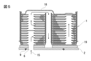
- FIG. 5 is a cross-sectional view taken along the line VV of FIG.
- FIG. 6 is an explanatory view showing a state in which the heat exchanger is attached to the casing 3 via the flange 2.
- FIG. 1 is a vertical cross-sectional view (A) of a main part of the mounting structure of the heat exchanger of the present invention and a partially enlarged view (B) thereof, and FIG. 1B shows a state before fastening the bolt 11.
- FIG. 2 is a vertical cross-sectional view (A) of a main part of the flange 2 of the present invention
- FIG. 4 is a plan view of the heat exchanger
- FIG. 5 is a sectional view taken along the line VV of FIG.
- FIG. 6 is a mounting structure of the heat exchanger. It is a schematic diagram. As shown in FIG. 6, the heat exchanger 1 has a core in which a large number of dish-shaped plates are laminated. A flange 2 is arranged at the lower end of the core, and the flange 2 is liquidtightly connected to the casing 3 via an O-ring 9. The flange 2 of this heat exchanger seals the oil inlet / outlet with one O-ring 9. Then, the oil 15 is guided from the case-side flow path hole 7 of the casing 3 to the inside of the heat exchanger 1 via the flange 2. In the heat exchanger 1, as shown in FIG. 5, the oil flow path and the cooling water flow path are alternately laminated.
- the present invention is characterized by a mounting structure of a flange 2 provided at an end of a heat exchanger 1 and a casing 3.
- a relatively thick base 19 is connected to the lowermost plate of the core of the heat exchanger 1, and the heat exchanger 1 and the flange 2 are connected via the base 19. ..
- the base 19 and the flange 2 are integrally joined.
- an annular groove 5 is formed on the lower surface of the flange 2 (the surface on the connection side with the casing 3).
- the annular groove 5 is provided in the band region 4 formed in an annular shape.
- an outer band 4a is formed on the outer side with respect to the center of the flange 2
- an inner band 4b is formed on the inner side.
- the outer band 4a protrudes slightly toward the casing 3 side from the flat surface of the lower surface of the flange 2 by H1.
- the flat surface of the casing 3 and the surface of the metal touch 12 are formed.
- the metal touch means that the flat surfaces of the metal come into contact with each other. Then, as shown in FIG.
- the inner band 4b is formed with a convex stepped surface 8 slightly protruding from the outer band 4a and the inner band 4b on the casing 3 side by H2.
- the amount of protrusion is 0.02 mm or more and 0.3 mm or less from the plane of the outer band 4a as a reference.
- the flatness of the convex stepped surface 8 is 0.1 mm or less.
- a flow path hole 6 is formed in the center of the convex step surface 8.
- the convex stepped surface 8 in FIG. 2D projects toward the casing 3 side by H3 with respect to the flat surface of the lower surface of the flange 2.
- the amount of protrusion of H3 is substantially the same as the amount of protrusion of H1 and H2 described above.
- One or more bolt holes 10 are formed in the flange 2, through which bolts 11 are inserted.
- the hole edge portion of the bolt hole 10 slightly protrudes in the same direction as the outer band 4a and the inner band 4b.
- the amount of protrusion of the plane of the hole edge portion of the bolt hole 10 and the planes of the outer band 4a and the inner band 4b is substantially flush with the exception of the convex step surface 8.
- a case-side flow path hole 7 is provided in the casing 3 in line with the flow path hole 6 that serves as an oil inlet. Further, a case-side outlet 17a is provided in line with the oil outlet 17 of the flange 2.
- each portion of the connecting surface 13 of the casing 3 in contact with the flange 2 is formed flush with each other, and the connecting surface 13 faces the surface of the metal touch 12 of the flange 2. Then, when the flange 2 is brought into contact with the casing 3, the convex step surface 8 comes into contact with the connecting surface 13 of the casing 3.
- FIG. 1B when the flange 2 of the heat exchanger 1 is placed on the flush connection surface 13 of the casing 3, the convex step surface 8 and the connection surface 13 come into contact with each other.
- the bolt 11 is fastened in this state, the surface of the metal touch 12 of the flange 2 and the connection surface 13 of the casing 3 are in pressure contact with each other to improve the sealing performance of the O-ring 9.
- the pressure contact amount is the difference between the convex step surface 8 and the pair of band regions 4.
- the amount of protrusion of the convex step surface 8 slightly protruding from the inner band 4b toward the casing 3 is 0.02 mm or more and 0.3 mm or less from the plane of the outer band 4a, and the protrusion thereof.
- the heat dissipation amount of the heat exchanger increases by 3.2% to 5.0% and at the same time. , There was no oil leak. Further, when the structure of the convex stepped surface 8 is adopted, the conventional press method can be adopted as it is.
- the present invention can be used as a heat exchanger for a transmission or an engine of a vehicle or the like, and is particularly suitable for use as an oil cooler for them.
Abstract
Description
このとき、熱交換器のオイル出入口とケーシングとは、研磨された平面どうしが接触するメタルタッチを用いてシールが行なわれていた。 Conventionally, in a heat exchanger for an oil cooler, a large number of dish-shaped plates are laminated to form a core, a flange is placed at the end of the core, and the heat exchanger is attached to the casing via an O-ring on the flange. .. Then, the oil cooled by the heat exchanger is returned to the casing.
At this time, the oil inlet / outlet of the heat exchanger and the casing were sealed by using a metal touch in which the polished flat surfaces were in contact with each other.
そこで本発明は、オイルクーラとしての熱交換器のフランジにおけるオイル洩れを確実に防止することを課題とする。 In the mounting structure of the heat exchanger as an oil cooler, if the flange and the casing are sealed with a metal touch, a leak will occur at the oil inlet / outlet due to the finishing accuracy of the sealing surface, and the heat exchange performance of the oil cooler will deteriorate. I had something to do.
Therefore, it is an object of the present invention to surely prevent oil leakage in the flange of the heat exchanger as an oil cooler.
前記フランジ2の表面に、環状の平面からなる帯領域4を有し、その帯領域4内にシール用のOリング9が収納される環状溝5が形成され、
帯領域4の内側に少なくとも一つの流路孔6が形成されると共に、その流路孔6に対向してケーシング3にケース側流路孔7が設けられ、
前記フランジ2に接するケーシング3の表面の各部は面一に形成され、フランジ2とケーシング3とは前記帯領域4でメタルタッチ12を形成し、
フランジ2の流路孔6の孔縁部は、前記メタルタッチ12の面よりもケーシング3側に突出する凸段差面8に形成されたことを特徴とする熱交換器の取付構造である。
請求項2に記載の本発明は、請求項1に記載の熱交換器の取付構造において、
前記帯領域4は、前記環状溝5の外側に外側帯4aが形成され、内側に内側帯4bが形成され、その内側帯4bを含んで前記凸段差面8が設けられた熱交換器の取付構造である。
請求項3に記載の本発明は、請求項1または請求項2に記載の熱交換器の取付構造において、
前記凸段差面8は、前記メタルタッチ12の面に対して、0.02mm以上0.3mm以下で、その平面度が0.1mm以下である熱交換器の取付構造である。 The present invention according to
On the surface of the
At least one
Each part of the surface of the
The hole edge portion of the
The present invention according to
In the
The present invention according to
The
フランジ2の流路孔6の孔縁部は、メタルタッチ12の面よりもケーシング3側に突出する凸段差面8に形成されたものである。
これにより、凸段差面8の分だけ、フランジ2がメタルタッチ12の面よりケーシング3に強く圧接して、流路孔6の孔縁から流体が洩れ出ることを防止できる。それにより、熱交換性能を向上できる。
請求項2に記載の発明は、帯領域4の内側帯4bに凸段差面8が設けられたものである。
これにより、凸段差面8がOリング9に近接して、流体の洩れをさらに効果的に防止できる。
請求項3に記載の発明は、前記凸段差面8を、前記メタルタッチ12の面に対して、0.02mm以上0.3mm以下で、その平面度が0.1mm以下としたものである。
これにより、流体洩れのない、製造容易な熱交換器の取付構造を提供できる。即ち、上記数値範囲においては、流体の洩れがない。 In the invention according to
The hole edge portion of the
As a result, it is possible to prevent the
The invention according to
As a result, the
According to the third aspect of the present invention, the
This makes it possible to provide an easy-to-manufacture heat exchanger mounting structure without fluid leakage. That is, there is no fluid leakage in the above numerical range.
図2は本発明の取付構造のフランジ2の要部縦断面図であって、(A)は図3のII−II矢視図、(B)(C)(D)は図2(A)のB部C部D部の各拡大図。
図3は本発明のフランジ2の裏面側平面図。
図4は本発明の熱交換器の平面図。
図5は図4のV−V矢視断面図。
図6は同熱交換器をケーシング3にフランジ2を介して取付けた状態を示す説明図。 1A and 1B show a main part of the heat exchanger of the present invention, FIG. 1A shows an exploded perspective view thereof, FIG. 1B shows a mounting state thereof, and shows a state before fastening the
2A and 2B are vertical cross-sectional views of a main part of the
FIG. 3 is a plan view of the back surface of the
FIG. 4 is a plan view of the heat exchanger of the present invention.
FIG. 5 is a cross-sectional view taken along the line VV of FIG.
FIG. 6 is an explanatory view showing a state in which the heat exchanger is attached to the
図1は本発明の熱交換器の取付構造の要部縦断面図(A)及びその部分拡大図(B)であって、(B)はボルト11の締結前の状態を示す。
また、図2は本発明のフランジ2の要部縦断面図(A)及び、(B)(C)(D)は図2(A)のB部C部D部の各拡大図であり、図3は本発明のフランジ2の裏面側平面図、図4は同熱交換器の平面図、図5は図4のV−V矢視断面図、図6は同熱交換器の取付構造の略図である。
この熱交換器1は、図6に示す如く、多数の皿状プレートが積層されたコアを有している。そのコアの下端にはフランジ2が配置されており、そのフランジ2がケーシング3にOリング9を介して液密に接続されている。この熱交換器のフランジ2は、オイルの出入口を1つのOリング9でシールしている。
そして、オイル15がケーシング3のケース側流路孔7よりフランジ2を介し熱交換器1の内部に導かれる。
熱交換器1は、図5に示す如く、オイル流路と冷却水流路とが交互に積層されている。フランジ2の流路孔6から流入したオイル15は、熱交換器1のオイル流路を蛇行状に流通する。そして、図4に示す冷却水14と、図5に示すオイル15との間で熱交換される。
冷却されたオイル15は、図4に示すオイル出口17からケーシング3に戻される。
本発明は、熱交換器1の端部に設けられたフランジ2とケーシング3との取付構造に特徴がある。
この例では、熱交換器1のコアの最下端のプレートには比較的厚みの厚いベース19が接続されており、そのベース19を介して、熱交換器1とフランジ2とが接続されている。ベース19とフランジ2は、一体に接合されている。
ここで、フランジ2の下面(ケーシング3との接続側の面)には、図3に示す如く、その表面に環状溝5が形成されている。その環状溝5は、環状に形成された帯領域4内に設けられている。この帯領域4は、フランジ2の中心に対して外側に外側帯4aが形成され、内側に内側帯4bが形成されている。
そして外側帯4aは、図2(B)に示す如く、フランジ2の下面の平面よりもケーシング3側に僅かにH1分だけ突出している。それにより、図1(B)において、ケーシング3の平面とメタルタッチ12の面を形成する。ここに、前記メタルタッチとは、金属の平面どうしが接触することをいう。
そして、その内側帯4bには、図2(C)に示す如く、外側帯4a、内側帯4bよりもケーシング3側に僅かにH2分だけ突出した凸段差面8が形成されている。その突出量は、外側帯4aの平面を基準とし、その平面から0.02mm以上0.3mm以下である。そして、その凸段差面8の平面度は0.1mm以下である。
その凸段差面8の中央には、流路孔6が穿設されている。
参考までに、図2(D)における凸段差面8は、フランジ2の下面の平面よりもケーシング3側にH3分突出することになる。このH3の突出量は、前述のH1とH2を合わせた突出量と略同一となる。
フランジ2には1つ以上のボルト孔10が穿設され、そこにボルト11が挿通される。このボルト孔10の孔縁部は、外側帯4a、内側帯4bと同じ方向に僅かに突出している。ボルト孔10の孔縁部の平面と、外側帯4a、内側帯4bの平面の突出量は、凸段差面8を除いて、略面一となる。
オイルの入口となる流路孔6に整合して、ケーシング3にケース側流路孔7が設けられる。さらに、フランジ2のオイル出口17に整合して、ケース側出口17aが設けられている。
フランジ2が接するケーシング3の接続面13の各部は面一に形成され、その接続面13がフランジ2のメタルタッチ12の面に対向する。
そして、フランジ2をケーシング3に接触させたとき、凸段差面8がケーシング3の接続面13に接触する。
図1(B)において、熱交換器1のフランジ2をケーシング3の面一な接続面13に載置すると、凸段差面8と接続面13とが接触する。この状態で、ボルト11を締結すると、フランジ2のメタルタッチ12の面と、ケーシング3の接続面13とが圧接し、Oリング9のシール性を高める。その圧接量は、凸段差面8と一対の帯領域4との差分である。
その結果、流路孔6内のオイルが外部に洩れることを阻止する。
実験によれば、内側帯4bからケーシング3側に僅かに突出した凸段差面8の突出量を、外側帯4aの平面を基準とし、その平面から0.02mm以上0.3mm以下で、その凸段差面8の平面度は0.1mm以下とし、オイルの流量を低流量、中流量、大流量に変えたとき、熱交換器の放熱量が、3.2%~5.0%増加すると共に、オイル洩れは存在しなかった。
また、上記の凸段差面8の構造を採用するとき、従来のプレス工法をそのまま採用することができた。 Next, an embodiment of the present invention will be described with reference to the drawings.
FIG. 1 is a vertical cross-sectional view (A) of a main part of the mounting structure of the heat exchanger of the present invention and a partially enlarged view (B) thereof, and FIG. 1B shows a state before fastening the
Further, FIG. 2 is a vertical cross-sectional view (A) of a main part of the
As shown in FIG. 6, the
Then, the
In the
The cooled
The present invention is characterized by a mounting structure of a
In this example, a relatively
Here, as shown in FIG. 3, an
As shown in FIG. 2B, the
Then, as shown in FIG. 2C, the
A flow path hole 6 is formed in the center of the
For reference, the convex stepped
One or more bolt holes 10 are formed in the
A case-side flow path hole 7 is provided in the
Each portion of the connecting
Then, when the
In FIG. 1B, when the
As a result, the oil in the flow path hole 6 is prevented from leaking to the outside.
According to the experiment, the amount of protrusion of the
Further, when the structure of the convex stepped
2 フランジ
3 ケーシング
4 帯領域
4a 外側帯
4b 内側帯
5 環状溝
6 流路孔
7 ケース側流路孔
8 凸段差面
9 Oリング
9a 爪部
10 ボルト孔
11 ボルト
12 メタルタッチ
13 接続面
14 冷却水
15 オイル
17 オイル出口
17a ケース側出口
18 バイパス
19 ベース 1
Claims (3)
- 熱交換器(1)の一端にフランジ(2)が設けられ、そのフランジ(2)がケーシング(3)の表面に接続される熱交換器の取付構造において、
前記フランジ(2)の表面に、環状の平面からなる帯領域(4)を有し、その帯領域(4)内にシール用のOリング(9)が収納される環状溝(5)が形成され、
帯領域(4)の内側に少なくとも一つの流路孔(6)が形成されると共に、その流路孔(6)に対向してケーシング(3)にケース側流路孔(7)が設けられ、
前記フランジ(2)に接するケーシング(3)の表面の各部は面一に形成され、フランジ(2)とケーシング(3)とは前記帯領域(4)でメタルタッチ(12)を形成し、
フランジ(2)の流路孔(6)の孔縁部は、前記メタルタッチ(12)の面よりもケーシング(3)側に突出する凸段差面(8)に形成されたことを特徴とする熱交換器の取付構造。 In the heat exchanger mounting structure in which a flange (2) is provided at one end of the heat exchanger (1) and the flange (2) is connected to the surface of the casing (3).
The surface of the flange (2) has a band region (4) made of an annular flat surface, and an annular groove (5) in which an O-ring (9) for sealing is housed is formed in the band region (4). Being done
At least one flow path hole (6) is formed inside the band region (4), and a case-side flow path hole (7) is provided in the casing (3) facing the flow path hole (6). ,
Each part of the surface of the casing (3) in contact with the flange (2) is formed flush with each other, and the flange (2) and the casing (3) form a metal touch (12) in the band region (4).
The hole edge portion of the flow path hole (6) of the flange (2) is characterized in that it is formed on a convex stepped surface (8) protruding toward the casing (3) from the surface of the metal touch (12). Heat exchanger mounting structure. - 請求項1に記載の熱交換器の取付構造において、
前記帯領域(4)は、前記環状溝(5)の外側に外側帯(4a)が形成され、内側に内側帯(4b)が形成され、その内側帯(4b)を含んで前記凸段差面(8)が設けられた熱交換器の取付構造。 In the heat exchanger mounting structure according to claim 1,
In the band region (4), an outer band (4a) is formed on the outer side of the annular groove (5), an inner band (4b) is formed on the inner side, and the convex step surface includes the inner band (4b). The mounting structure of the heat exchanger provided with (8). - 請求項1または請求項2に記載の熱交換器の取付構造において、
前記凸段差面(8)は、前記メタルタッチ(12)の面に対して、0.02mm以上0.3mm以下で、その平面度が0.1mm以下である熱交換器の取付構造。
ここに、前記メタルタッチとは、金属の平面どうしが接触することをいう。 In the heat exchanger mounting structure according to claim 1 or 2.
The convex step surface (8) is a heat exchanger mounting structure having a flatness of 0.02 mm or more and 0.3 mm or less and a flatness of 0.1 mm or less with respect to the surface of the metal touch (12).
Here, the metal touch means that the flat surfaces of the metal come into contact with each other.
Priority Applications (2)
| Application Number | Priority Date | Filing Date | Title |
|---|---|---|---|
| JP2022541719A JPWO2022030566A1 (en) | 2020-08-06 | 2021-07-28 | |
| CN202180061305.1A CN116194729A (en) | 2020-08-06 | 2021-07-28 | Mounting structure of heat exchanger |
Applications Claiming Priority (2)
| Application Number | Priority Date | Filing Date | Title |
|---|---|---|---|
| JP2020-134029 | 2020-08-06 | ||
| JP2020134029 | 2020-08-06 |
Publications (1)
| Publication Number | Publication Date |
|---|---|
| WO2022030566A1 true WO2022030566A1 (en) | 2022-02-10 |
Family
ID=80117544
Family Applications (1)
| Application Number | Title | Priority Date | Filing Date |
|---|---|---|---|
| PCT/JP2021/029039 WO2022030566A1 (en) | 2020-08-06 | 2021-07-28 | Attachment structure for heat exchanger |
Country Status (3)
| Country | Link |
|---|---|
| JP (1) | JPWO2022030566A1 (en) |
| CN (1) | CN116194729A (en) |
| WO (1) | WO2022030566A1 (en) |
Cited By (2)
| Publication number | Priority date | Publication date | Assignee | Title |
|---|---|---|---|---|
| WO2024024466A1 (en) * | 2022-07-27 | 2024-02-01 | 株式会社ティラド | Plate stacking-type heat exchanger |
| WO2024024465A1 (en) * | 2022-07-27 | 2024-02-01 | 株式会社ティラド | Stacked plate heat exchanger |
Citations (3)
| Publication number | Priority date | Publication date | Assignee | Title |
|---|---|---|---|---|
| JPS6374973U (en) * | 1986-10-31 | 1988-05-18 | ||
| JP2002332818A (en) * | 2001-05-10 | 2002-11-22 | Mahle Tennex Corp | Filter integrated oil cooler |
| JP2011069511A (en) * | 2009-09-24 | 2011-04-07 | Toyota Motor Corp | Heat exchanger |
-
2021
- 2021-07-28 CN CN202180061305.1A patent/CN116194729A/en active Pending
- 2021-07-28 WO PCT/JP2021/029039 patent/WO2022030566A1/en active Application Filing
- 2021-07-28 JP JP2022541719A patent/JPWO2022030566A1/ja active Pending
Patent Citations (3)
| Publication number | Priority date | Publication date | Assignee | Title |
|---|---|---|---|---|
| JPS6374973U (en) * | 1986-10-31 | 1988-05-18 | ||
| JP2002332818A (en) * | 2001-05-10 | 2002-11-22 | Mahle Tennex Corp | Filter integrated oil cooler |
| JP2011069511A (en) * | 2009-09-24 | 2011-04-07 | Toyota Motor Corp | Heat exchanger |
Cited By (2)
| Publication number | Priority date | Publication date | Assignee | Title |
|---|---|---|---|---|
| WO2024024466A1 (en) * | 2022-07-27 | 2024-02-01 | 株式会社ティラド | Plate stacking-type heat exchanger |
| WO2024024465A1 (en) * | 2022-07-27 | 2024-02-01 | 株式会社ティラド | Stacked plate heat exchanger |
Also Published As
| Publication number | Publication date |
|---|---|
| JPWO2022030566A1 (en) | 2022-02-10 |
| CN116194729A (en) | 2023-05-30 |
Similar Documents
| Publication | Publication Date | Title |
|---|---|---|
| WO2022030566A1 (en) | Attachment structure for heat exchanger | |
| US6298910B1 (en) | Aluminum-made heat exchanger with brazed joint portion | |
| EP3124907B1 (en) | Heat exchange device | |
| EP2856061B1 (en) | Heat exchanger with adapter module | |
| US20070256822A1 (en) | Heat exchanger | |
| CN106907210B (en) | Oil bypass structure of oil cooler | |
| JP2002168591A (en) | Heat exchanger made of aluminum | |
| US11274884B2 (en) | Heat exchanger module with an adapter module for direct mounting to a vehicle component | |
| CN108733183B (en) | Water cooling head of water cooling radiator for heat dissipation of computer internal parts | |
| WO2011009412A1 (en) | Heat exchanger assembly and machine using the same | |
| JP2001050673A (en) | Plate-type heat exchanger for cooling oil for automobile | |
| JP2936775B2 (en) | Heat exchanger | |
| KR20190142872A (en) | Oil cooler | |
| WO2021063220A1 (en) | Heat exchanger and manufacturing method therefor | |
| JP3286699B2 (en) | Aluminum laminated heat exchanger | |
| CN113027729B (en) | Air compressor machine with high-efficient heat dissipation function | |
| US20240027145A1 (en) | Apparatus | |
| CN220929500U (en) | Engine oil cooler | |
| CN219061981U (en) | Integrated component | |
| JP3024654B2 (en) | Oil cooler | |
| JP7323976B2 (en) | Flange structure and heat exchanger with same structure | |
| JPS58148393A (en) | Heat exchanger | |
| JP7385011B2 (en) | Heat exchanger | |
| CN219200179U (en) | Sealing structure for cold plate seal head of spacecraft | |
| WO2024084972A1 (en) | Surface contact heat exchanger |
Legal Events
| Date | Code | Title | Description |
|---|---|---|---|
| 121 | Ep: the epo has been informed by wipo that ep was designated in this application |
Ref document number: 21852271 Country of ref document: EP Kind code of ref document: A1 |
|
| ENP | Entry into the national phase |
Ref document number: 2022541719 Country of ref document: JP Kind code of ref document: A |
|
| WWE | Wipo information: entry into national phase |
Ref document number: 18019585 Country of ref document: US |
|
| NENP | Non-entry into the national phase |
Ref country code: DE |
|
| 122 | Ep: pct application non-entry in european phase |
Ref document number: 21852271 Country of ref document: EP Kind code of ref document: A1 |