WO2022030453A1 - Procédé de commande de communication - Google Patents
Procédé de commande de communication Download PDFInfo
- Publication number
- WO2022030453A1 WO2022030453A1 PCT/JP2021/028636 JP2021028636W WO2022030453A1 WO 2022030453 A1 WO2022030453 A1 WO 2022030453A1 JP 2021028636 W JP2021028636 W JP 2021028636W WO 2022030453 A1 WO2022030453 A1 WO 2022030453A1
- Authority
- WO
- WIPO (PCT)
- Prior art keywords
- cell
- mbs
- control method
- notification message
- communication control
- Prior art date
Links
- 238000004891 communication Methods 0.000 title claims abstract description 37
- 238000000034 method Methods 0.000 title claims abstract description 32
- 230000005540 biological transmission Effects 0.000 claims abstract description 58
- 238000010295 mobile communication Methods 0.000 claims abstract description 21
- 238000005516 engineering process Methods 0.000 claims description 19
- 230000007774 longterm Effects 0.000 claims description 3
- 125000004122 cyclic group Chemical group 0.000 claims description 2
- 230000008859 change Effects 0.000 abstract description 13
- 238000012986 modification Methods 0.000 description 30
- 230000004048 modification Effects 0.000 description 30
- 238000010586 diagram Methods 0.000 description 15
- 230000006870 function Effects 0.000 description 10
- 230000011664 signaling Effects 0.000 description 5
- 238000007726 management method Methods 0.000 description 4
- 230000008569 process Effects 0.000 description 4
- 238000012545 processing Methods 0.000 description 4
- 241000700159 Rattus Species 0.000 description 3
- 238000005259 measurement Methods 0.000 description 3
- 238000013507 mapping Methods 0.000 description 2
- 230000004044 response Effects 0.000 description 2
- 230000001052 transient effect Effects 0.000 description 2
- 230000006835 compression Effects 0.000 description 1
- 238000007906 compression Methods 0.000 description 1
- 230000006837 decompression Effects 0.000 description 1
- 238000013461 design Methods 0.000 description 1
- 238000013468 resource allocation Methods 0.000 description 1
- 239000004065 semiconductor Substances 0.000 description 1
- 230000001360 synchronised effect Effects 0.000 description 1
- 238000012546 transfer Methods 0.000 description 1
Images


Classifications
-
- H—ELECTRICITY
- H04—ELECTRIC COMMUNICATION TECHNIQUE
- H04W—WIRELESS COMMUNICATION NETWORKS
- H04W36/00—Hand-off or reselection arrangements
- H04W36/0005—Control or signalling for completing the hand-off
- H04W36/0007—Control or signalling for completing the hand-off for multicast or broadcast services, e.g. MBMS
-
- H—ELECTRICITY
- H04—ELECTRIC COMMUNICATION TECHNIQUE
- H04W—WIRELESS COMMUNICATION NETWORKS
- H04W72/00—Local resource management
- H04W72/30—Resource management for broadcast services
-
- H—ELECTRICITY
- H04—ELECTRIC COMMUNICATION TECHNIQUE
- H04W—WIRELESS COMMUNICATION NETWORKS
- H04W36/00—Hand-off or reselection arrangements
- H04W36/0005—Control or signalling for completing the hand-off
- H04W36/0055—Transmission or use of information for re-establishing the radio link
- H04W36/0061—Transmission or use of information for re-establishing the radio link of neighbour cell information
-
- H—ELECTRICITY
- H04—ELECTRIC COMMUNICATION TECHNIQUE
- H04W—WIRELESS COMMUNICATION NETWORKS
- H04W4/00—Services specially adapted for wireless communication networks; Facilities therefor
- H04W4/06—Selective distribution of broadcast services, e.g. multimedia broadcast multicast service [MBMS]; Services to user groups; One-way selective calling services
-
- H—ELECTRICITY
- H04—ELECTRIC COMMUNICATION TECHNIQUE
- H04W—WIRELESS COMMUNICATION NETWORKS
- H04W72/00—Local resource management
- H04W72/04—Wireless resource allocation
- H04W72/044—Wireless resource allocation based on the type of the allocated resource
- H04W72/0457—Variable allocation of band or rate
-
- H—ELECTRICITY
- H04—ELECTRIC COMMUNICATION TECHNIQUE
- H04W—WIRELESS COMMUNICATION NETWORKS
- H04W36/00—Hand-off or reselection arrangements
- H04W36/08—Reselecting an access point
-
- H—ELECTRICITY
- H04—ELECTRIC COMMUNICATION TECHNIQUE
- H04W—WIRELESS COMMUNICATION NETWORKS
- H04W36/00—Hand-off or reselection arrangements
- H04W36/14—Reselecting a network or an air interface
Definitions
- the present invention relates to a communication control method used in a mobile communication system.
- NR New Radio
- RAT Radio Access Technology
- LTE Long Term Evolution
- the communication control method is a communication control method used in a mobile communication system that provides a multicast / broadcast service (MBS), in which a base station transmits MBS data to a user apparatus in a cell 1. And, the base station sends a notification message to the user apparatus indicating that the MBS cell, which is a cell used for transmitting or receiving the MBS data, is changed from the first cell to the second cell, and the MBS.
- MBS multicast / broadcast service
- the communication control method is a communication control method used in a mobile communication system that provides a multicast / broadcast service (MBS), and a base station that manages the first cell is different from the first cell.
- the notification message relating to the MBS transmission in the two cells is to be transmitted to the user apparatus in the first cell, and the notification message includes wireless access technical information indicating the wireless access technology used by the second cell for the MBS transmission and the said.
- the second cell contains at least one of the bandwidth portion information indicating the bandwidth portion used for the MBS transmission.
- the communication control method is a communication control method used in a mobile communication system that provides a multicast / broadcast service (MBS), in which a user device that supports a plurality of wireless access technologies is a user device, and the user device is an MBS.
- MBS multicast / broadcast service
- the wireless access technology used for receiving data is selected from the plurality of wireless access technologies, and the user apparatus transmits a message indicating the selected wireless access technology to the base station.
- NR 5G system
- the purpose of this disclosure is to realize an improved multicast / broadcast service.
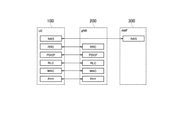
- FIG. 1 is a diagram showing a configuration of a mobile communication system according to an embodiment.
- This mobile communication system complies with the 5th generation system (5GS: 5th Generation System) of the 3GPP standard.
- 5GS 5th Generation System
- 5GS will be described as an example, but an LTE (Long Term Evolution) system may be applied to a mobile communication system at least partially.
- mobile communication systems include a user device (UE: User Equipment) 100, a 5G radio access network (NG-RAN: Next Generation Radio Access Network) 10, and a 5G core network (5GC: 5G). It has Core Network) 20.
- UE User Equipment
- NG-RAN Next Generation Radio Access Network
- 5GC 5G core network
- the UE 100 is a mobile wireless communication device.
- the UE 100 may be any device as long as it is a device used by the user.
- the UE 100 may be a mobile phone terminal (including a smartphone), a tablet terminal, a notebook PC, or a communication module (communication card or communication card). (Including a chip set), a sensor or a device provided on the sensor, a vehicle or a device provided on the vehicle (Vehicle UE), a vehicle or a device provided on the vehicle (Arial UE).
- the NG-RAN 10 includes a base station (referred to as "gNB” in a 5G system) 200.
- the gNB 200 are connected to each other via the Xn interface, which is an interface between base stations.
- the gNB 200 manages one or more cells.
- the gNB 200 performs wireless communication with the UE 100 that has established a connection with its own cell.
- the gNB 200 has a radio resource management (RRM) function, a routing function for user data (hereinafter, simply referred to as “data”), a measurement control function for mobility control / scheduling, and the like.
- RRM radio resource management
- Cell is used as a term to indicate the smallest unit of a wireless communication area.
- the term “cell” is also used to indicate a function or resource for wireless communication with the UE 100.
- One cell belongs to one carrier frequency.
- gNB can also connect to EPC (Evolved Packet Core), which is the core network of LTE.
- EPC Evolved Packet Core
- LTE base stations can also be connected to 5GC.
- the LTE base station and gNB can also be connected via an inter-base station interface.
- 5GC20 includes AMF (Access and Mobility Management Function) and UPF (User Plane Function) 300.
- the AMF performs various mobility controls and the like for the UE 100.
- the AMF manages the mobility of the UE 100 by communicating with the UE 100 using NAS (Non-Access Stratum) signaling.
- UPF controls data transfer.
- the AMF and UPF are connected to the gNB 200 via the NG interface, which is an interface between the base station and the core network.
- FIG. 2 is a diagram showing a configuration of a UE 100 (user device) according to an embodiment.
- the UE 100 includes a receiving unit 110, a transmitting unit 120, and a control unit 130.
- the receiving unit 110 performs various receptions under the control of the control unit 130.
- the receiving unit 110 includes an antenna and a receiver.
- the receiver converts the radio signal received by the antenna into a baseband signal (received signal) and outputs it to the control unit 130.
- the transmission unit 120 performs various transmissions under the control of the control unit 130.
- the transmitter 120 includes an antenna and a transmitter.
- the transmitter converts the baseband signal (transmission signal) output by the control unit 130 into a radio signal and transmits it from the antenna.
- the control unit 130 performs various controls on the UE 100.
- the control unit 130 includes at least one processor and at least one memory.
- the memory stores a program executed by the processor and information used for processing by the processor.
- the processor may include a baseband processor and a CPU (Central Processing Unit).
- the baseband processor modulates / demodulates and encodes / decodes the baseband signal.
- the CPU executes a program stored in the memory to perform various processes.
- FIG. 3 is a diagram showing the configuration of the gNB 200 (base station) according to the embodiment.
- the gNB 200 includes a transmission unit 210, a reception unit 220, a control unit 230, and a backhaul communication unit 240.
- the transmission unit 210 performs various transmissions under the control of the control unit 230.
- the transmitter 210 includes an antenna and a transmitter.
- the transmitter converts the baseband signal (transmission signal) output by the control unit 230 into a radio signal and transmits it from the antenna.
- the receiving unit 220 performs various receptions under the control of the control unit 230.
- the receiving unit 220 includes an antenna and a receiver.
- the receiver converts the radio signal received by the antenna into a baseband signal (received signal) and outputs it to the control unit 230.
- the control unit 230 performs various controls on the gNB 200.
- the control unit 230 includes at least one processor and at least one memory.
- the memory stores a program executed by the processor and information used for processing by the processor.
- the processor may include a baseband processor and a CPU.
- the baseband processor modulates / demodulates and encodes / decodes the baseband signal.
- the CPU executes a program stored in the memory to perform various processes.
- the backhaul communication unit 240 is connected to an adjacent base station via an interface between base stations.
- the backhaul communication unit 240 is connected to the AMF / UPF 300 via the base station-core network interface.
- the gNB is composed of a CU (Central Unit) and a DU (Distributed Unit) (that is, the functions are divided), and both units may be connected by an F1 interface.
- FIG. 4 is a diagram showing a configuration of a protocol stack of a wireless interface of a user plane that handles data.
- the wireless interface protocol of the user plane includes a physical (PHY) layer, a MAC (Medium Access Control) layer, an RLC (Radio Link Control) layer, and a PDCP (Packet Data Convergence Protocol) layer. It has an SDAP (Service Data Adjustment Protocol) layer.
- PHY physical
- MAC Medium Access Control
- RLC Radio Link Control
- PDCP Packet Data Convergence Protocol
- SDAP Service Data Adjustment Protocol
- the PHY layer performs coding / decoding, modulation / demodulation, antenna mapping / demapping, and resource mapping / demapping. Data and control information are transmitted between the PHY layer of the UE 100 and the PHY layer of the gNB 200 via a physical channel.
- the MAC layer performs data priority control, retransmission processing by hybrid ARQ (HARQ), random access procedure, and the like. Data and control information are transmitted between the MAC layer of the UE 100 and the MAC layer of the gNB 200 via the transport channel.
- the MAC layer of gNB200 includes a scheduler. The scheduler determines the transport format (transport block size, modulation / coding method (MCS)) of the upper and lower links and the resource block allocated to the UE 100.
- MCS modulation / coding method
- the RLC layer transmits data to the receiving RLC layer by using the functions of the MAC layer and the PHY layer. Data and control information are transmitted between the RLC layer of the UE 100 and the RLC layer of the gNB 200 via a logical channel.
- the PDCP layer performs header compression / decompression and encryption / decryption.
- the SDAP layer maps the IP flow, which is a unit for performing QoS control by the core network, with the wireless bearer, which is a unit for performing QoS control by AS (Access Stratum).
- AS Access Stratum
- FIG. 5 is a diagram showing a configuration of a protocol stack of a wireless interface of a control plane that handles signaling (control signal).
- the protocol stack of the radio interface of the control plane has an RRC (Radio Resource Control) layer and a NAS (Non-Access Stratum) layer in place of the SDAP layer shown in FIG.
- RRC signaling for various settings is transmitted between the RRC layer of UE100 and the RRC layer of gNB200.
- the RRC layer controls logical channels, transport channels, and physical channels in response to the establishment, re-establishment, and release of radio bearers.
- RRC connection connection between the RRC of the UE 100 and the RRC of the gNB 200
- the UE 100 is in the RRC connected state.
- RRC connection no connection between the RRC of the UE 100 and the RRC of the gNB 200
- the UE 100 is in the RRC idle state.
- the connection between the RRC of the UE 100 and the RRC of the gNB 200 is suspended, the UE 100 is in the RRC inactive state.
- the NAS layer located above the RRC layer performs session management, mobility management, etc.
- NAS signaling is transmitted between the NAS layer of the UE 100 and the NAS layer of the AMF300.
- the UE 100 has an application layer and the like in addition to the wireless interface protocol.
- MBS is a service that broadcasts or multicasts data from NG-RAN10 to UE100, that is, one-to-many (PTM: Point To Multipoint) data transmission.
- PTM Point To Multipoint
- MBS may be referred to as MBMS (Multicast Broadcast and Multicast Service).
- MBS use cases include public security communication, mission-critical communication, V2X (Vehicle to Everything) communication, IPv4 or IPv6 multicast distribution, IPTV, group communication, software distribution, and the like.
- V2X Vehicle to Everything
- IPv4 or IPv6 multicast distribution IPTV, group communication, software distribution, and the like.
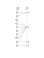
- FIG. 6 is a diagram showing the correspondence between the downlink logical channel (Logical channel) and the transport channel (Transport channel) according to the embodiment.
- the logical channels used for MBSFN transmission are MTCH (Multicast Traffic Channel) and MCCH (Multicast Control Channel), and the transport channel used for MBSFN transmission is MCH (Multicast Control Channel).
- MBSFN transmission is mainly designed for multi-cell transmission, and each cell performs synchronous transmission of the same signal (same data) in the same MBSFN subframe in an MBSFN area composed of a plurality of cells.
- SC-PTM transmission The logical channels used for SC-PTM transmission are SC-MTCH (Single Cell Multicast Traffic Channel) and SC-MCCH (Single Cell Multicast Control Channel), and the transport channels used for SC-PTM transmission are DL-SCH (Downlink). ).
- SC-PTM transmission is designed primarily for single-cell transmission and performs broadcast or multicast data transmission on a cell-by-cell basis.
- the physical channels used for SC-PTM transmission are PDCCH (Physical Downlink Control Channel) and PDSCH (Physical Downlink Control Channel), and dynamic resource allocation is possible.
- MBS may be provided using the MBSFN transmission method.
- MBS data means data transmitted by MBS transmission
- MBS transmission means multicast or broadcast.
- the multicast control channel means MCCH or SC-MCCH
- the multicast traffic channel means MTCH or SC-MTCH.
- the network can deliver different MBS data for each MBS session.
- the MBS session is identified by at least one of TMGI (Temporary Mobile Group Identity), session identifier, and G-RNTI (Group Cell Radio Network Strength Identity).
- TMGI Temporal Mobile Group Identity
- G-RNTI Group Cell Radio Network Strength Identity
- at least one of these identifiers will be referred to as an MBS session identifier.
- the MBS session identifier may be referred to as an MBS group identifier (or multicast group identifier).
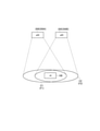
- FIG. 7 is a diagram showing an example of the operating environment according to the embodiment.
- gNB200 manages cell C1 (first cell) and cell C2 (second cell).
- cell C1 first cell
- cell C2 second cell
- the cell sizes of cells C1 and C2 may be different from each other.
- Cell C1 is operated at frequency F1 and cell C2 is operated at frequency F2. That is, the frequencies (carrier frequencies) of the cells C1 and C2 are different from each other.
- the respective geographical areas of cell C1 and cell C2 overlap at least partially. Such relationships between cells are sometimes referred to as adjacent cells.
- the UE 100 is located in the overlapping region of the cells C1 and C2.
- FIG. 8 is a diagram showing another example of the operating environment according to the embodiment.
- FIG. 8 shows an example in which the two base stations that manage the cell C1 and the cell C2 are NR base stations having the same radio access technology.
- the two base stations that manage the cell C1 and the cell C2 may have different radio access technologies from each other.
- one may be an NR base station (gNB) and the other may be an LTE base station (eNB).
- the operation according to one embodiment is a cell used for transmitting or receiving MBS data when the UE 100 is receiving MBS data transmitted in cell C1 in the operating environment as shown in FIGS. 8 and 9.
- the present invention relates to an operation of changing an MBS cell from cell C1 to cell C2.
- the gNB 200 that manages the cell C1 decides to change the MBS cell from the cell C1 to the cell C2 in response to the increase in the load due to the congestion of the cell C1. This makes it possible to distribute the load among the cells.
- the communication control method is a step in which the gNB 200 transmits MBS data to the UE 100 in the cell C1 and an MBS cell which is a cell used by the gNB 200 to transmit or receive the MBS data from the cell C1 to the cell C2. It has a step of transmitting a notification message indicating change to the UE 100 and a step of receiving the MBS data from the gNB 200 by the UE 100 receiving the notification message from the gNB 200. By transmitting such a notification message to the UE 100, the UE 100 knows that the MBS cell is changed, and it becomes easy to continue receiving the MBS data.
- the gNB 200 may transmit a notification message to the UE 100 as a control message transmitted on the multicast control channel or system information (SIB: System Information Block) transmitted on the broadcast control channel (BCCH: Broadcast Control Channel).
- SIB System Information Block
- BCCH Broadcast Control Channel
- the gNB 200 may transmit a notification message as a MAC CE (Control Element) or an RRC message, which is a control message of the MAC layer.
- the notification message is an information element indicating the timing for changing the MBS cell, an identifier indicating the cell C2 (cell identifier), an identifier indicating the frequency to which the cell C2 belongs (frequency identifier), and an identifier indicating the MBS session in which the MBS cell is changed (the notification message). Includes at least one of the MBS session identifiers).
- the notification message at least one of the information element indicating the timing of changing the MBS cell, the cell identifier, and the frequency identifier may be associated with the MBS session identifier.
- the notification message is transmitted by MAC CE and the multicast traffic channel and MAC CE are multiplexed, the MBS session identifier becomes obvious, so it is not necessary to explicitly notify the MBS session identifier.
- the notification message may include an information element indicating whether or not MBS transmission in cell C1 is stopped.
- An information element indicating that the MBS cell is changed from cell C1 to cell C2 and an information element indicating whether or not MBS transmission in cell C1 is stopped are shared, and "change” or "stop” is made depending on the content of this information element. May be indicated.
- the notification message may be a message notifying that the MBS cell will be changed within a certain period of time, or may be a message including the notification as an information element.
- the fixed period may be 0 (zero: immediate), may be a period of SC-MCCH modification boundary (or SIB modification boundary), or may be an arbitrary period set from gNB200. good.
- the time unit for the fixed period may be an SC-MCCH (or SIB) modification boundary unit, a wireless frame unit, a subframe unit, or a minute / second unit. good.
- the notification message may be a message notifying that the transmission cell is changed at a certain time, or may be a message including the notification as an information element.
- the time may be represented by a system frame number (SFN) or a hyper system frame number (H-SFN).
- the notification message may be a message notifying that the MBS session currently transmitting MBS data is also being transmitted in another cell, or may be a message including the notification as an information element.
- the notification message may be a message notifying information indicating the cells recommended to be received. In this case, since the same MBS session is transmitted simultaneously (double) in other cells, the UE 100 can smoothly change the receiving cell at any timing.
- the notification message may be a message notifying that the MBS session currently transmitting MBS data is recommended (or instructing) to change the cell, or may be a message including the notification as an information element. ..
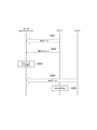
- FIG. 9 is a diagram showing an operation example 1. In operation example 1, it is assumed that the UE 100 is in the RRC connected state.
- step S101 gNB200 starts transmitting MBS data of a certain MBS session (here, MBS session identifier # 1) in cell C1.
- the UE 100 receives the MBS data from the cell C1.
- the gNB 200 decides to change the MBS cell for transmitting the MBS data corresponding to the MBS session identifier # 1 from the cell C1 to the cell C2.
- step S102 the gNB 200 sends a notification message in the cell C1 indicating that the MBS cell for transmitting the MBS data corresponding to the MBS session identifier # 1 is changed from the cell C1 to the cell C2.
- the UE 100 receives the notification message.
- step S103 the UE 100 transmits an indication (hereinafter referred to as MBS indication) for the UE 100 to perform a handover from cell C1 to cell C2 to the gNB 200 based on the notification message received in step S102.
- the handover is a cell switching operation of the UE 100 in the RRC connected state.
- the MBS indication may be an RRC message.
- the MBS indication includes an identifier of cell C2, which is a cell in which the UE 100 wants to receive MBS data, and / or an identifier of its frequency (frequency F2).
- the MBS indication may include an information element indicating whether the UE 100 gives priority to MBS reception over unicast reception.
- the MBS indication may be a message requesting the setting of the MBS reception period for the UE 100 to receive the MBS data in the cell C2 while maintaining the connection in the cell C1, or a message including the request as an information element. ..
- the MBS reception period is a period during which the UE 100 does not communicate with the cell C1, and may be referred to as an MBS reception gap.
- the MBS indication may be transmitted based on the conditions related to the switching of the MBS cell, or may be transmitted based on other conditions. Only in the latter case, the UE 100 may operate a prohibition timer for restricting repeated transmission of MBS indications. Specifically, the UE 100 starts the prohibition timer at the time of transmitting the MBS indication, and the transmission of the next MBS indication is prohibited until the prohibition timer expires. On the other hand, the UE 100 does not apply (ignore) the prohibition timer when transmitting the MBS indication based on the condition relating to the switching of the MBS cell.
- the gNB 200 grasps that the UE 100 wants to receive the MBS from the switching destination cell C2 (interested in the MBS reception) based on the MBS indication from the UE 100.
- the gNB 200 transmits a setting message, which is an RRC message, to the UE 100 in the cell C1.
- the setting message may be an RRC Reconnection message.
- the setting message may be a message for setting (instructing) the handover to the cell C2 in the UE 100.
- the setting message may be a message for setting the measurement of the cell C2 (frequency F2) and its report to the UE 100 prior to the handover. In this case, after the measurement report, the UE 100 is instructed to perform the handover.
- the setting message may be a message that sets the above-mentioned MBS reception period to the UE 100.
- step S105 the UE 100 performs a handover from the cell C1 to the cell C2.
- step S106 the gNB 200 starts transmitting the MBS data of the MBS session identifier # 1 in the cell C2.
- the UE 100 receives the MBS data from the cell C2.
- the MBS reception period is set in the UE 100
- the UE 100 receives the MBS data from the cell C2 in the set MBS reception period.
- step S107 the gNB 200 stops transmitting the MBS data of the MBS session identifier # 1 in the cell C1.
- Step S107 may be performed at the same time as step S106.
- FIG. 10 is a diagram showing an operation example 2. In operation example 2, it is assumed that the UE 100 is in the RRC idle state or the RRC inactive state.
- steps S201 and S202 are the same as steps S101 and S102 described above.
- step S203 the UE 100 reselects cells from cell C1 to cell C2 based on the notification message received from gNB200 (cell C1) in step S202.
- Cell reselection is a cell switching operation of the UE 100 in the RRC idle state or the RRC inactive state.
- the UE 100 may perform cell reselection from cell C1 to cell C2 by setting the frequency F2 to which cell C2 or cell C2 belongs as the highest priority for cell reselection.
- step S204 the gNB 200 starts transmitting the MBS data of the MBS session identifier # 1 in the cell C2.
- the UE 100 receives the MBS data from the cell C2.
- step S205 the gNB 200 stops transmitting the MBS data of the MBS session identifier # 1 in the cell C1.
- Step S205 may be performed at the same time as step S204.
- the cell C2 is an NR cell.
- cell C2 can be an LTE cell.
- the UE 100 which supports both NR and LTE radio access technology (RAT), is capable of both MBS reception from the NR cell and MBS transmission from the LTE cell.
- the UE 100 that supports only NR can receive MBS from the NR cell, but cannot receive MBS from the LTE cell. Therefore, in the modification example 1, the RAT of the cell C2 is notified in the notification message.
- RAT radio access technology
- the notification message according to the modification example 1 may have at least one of the above-mentioned notification message functions. However, the notification message according to the change example 1 may not have a function indicating that the MBS cell is changed from the cell C1 to the cell C2. In modification 1, cell C1 and cell C2 may transmit MBS data of MBS sessions different from each other. Such a premise is the same in each modification described later.
- FIG. 11 is a diagram showing the operation according to the modification example 1.
- the gNB 200 that manages the cell C1 transmits a notification message regarding MBS transmission in the cell C2 to the UE 100 in the cell C1.
- the notification message according to the first modification includes RAT information indicating the RAT used by the cell C2 for MBS transmission.
- the RAT information indicates whether the RAT used by the cell C2 for MBS transmission is LTE or NR.
- the notification message according to the first modification may be an SIB transmitted on the BCCH or a message transmitted on the multicast control channel.
- the gNB 200 When the adjacent cell (cell C2) is performing MBS transmission, the gNB 200 (cell C1) is set to at least one of the MBS session identifier of the MBS transmission, the cell ID of the adjacent cell, and the frequency to which the adjacent cell belongs.
- RAT information that identifies whether the MBS transmission is performed in LTE or NR is included in the notification message transmitted in cell C1.
- the RAT information is, for example, an information element such as "ratType ENUM (lte, nr)".
- the UE 100 in the RRC connected state receives the notification message from the gNB200 (cell C1), the RAT information included in the notification message, the RAT supported by the UE 100, and the MBS that the UE 100 is interested in receiving are received. Controls the transmission of the MBS information described above based on the session. The sequence of such operations is similar to the embodiment described above (see FIG. 9).
- the UE 100 determines that MBS reception is not possible for an MBS session cell frequency in which MBS transmission is performed in a RAT different from the RAT supported by the UE 100 based on the RAT information included in the notification message, and the UE 100 is interested in it. It may be excluded from the MBS session cell frequency that it has.
- the UE 100 may determine that MBS reception is possible for the MBS session cell frequency for which MBS transmission is performed by the RAT supported by the UE 100, and may be a candidate for the MBS session cell frequency that the UE 100 is interested in.
- the UE 100 in the RRC idle state or the RRC inactive state receives the notification message from the gNB200 (cell C1), the RAT information included in the notification message, the RAT it supports, and itself receive it. Control the cell reselection described above based on the MBS session of interest. The sequence of such operations is similar to the embodiment described above (see FIG. 10).
- Modification 2 assumes a scenario in which cell C2, which is an adjacent cell, is an NR cell.
- cell C2 is an NR cell
- a bandwidth portion (BWP: Bandwidth Part) that limits the transmission / reception band of the UE 100 may be set in the cell C2.
- FIG. 12 is a diagram showing an example of BWP.
- the BWP is a frequency portion of the entire band of the cell.
- BWP 1 having a bandwidth of 40 MHz and a subcarrier spacing of 15 kHz
- BWP 2 having a bandwidth of 10 MHz and a subcarrier spacing of 15 kHz
- BWP 2 having a bandwidth of 20 MHz and a subcarrier spacing of 60 kHz.
- BWP 3 is illustrated.
- the BWP is set from the gNB 200 to the UE 100, and switching from one BWP to the other BWP is controlled by the gNB 200.
- the gNB 200 can control the active BWP to switch to another BWP.
- the subcarrier interval and cyclic prefix can be variably set for each BWP.
- gNB200 can set a BWP for MBS transmission.
- the UE 100 located in the cell C1 knows in advance the settings related to the BWP for MBS transmission in the cell C2.
- the UE 100 can quickly receive MBS data from the cell C2 while switching the cell from the cell C1 to the cell C2.
- FIG. 13 is a diagram showing an operation according to the second modification.
- the gNB 200 that manages the cell C1 transmits a notification message regarding MBS transmission in the cell C2 to the UE 100 in the cell C1.
- the notification message according to the second modification includes BWP information indicating the BWP used by the cell C2 for MBS transmission.
- the notification message according to the modification example 2 may include RAT information in the same manner as the notification message according to the modification example 1.
- the BWP information may be included in the notification message only when the RAT information indicates NR in the notification message.
- the notification message according to the second modification may be an SIB transmitted on the BCCH or a message transmitted on the multicast control channel.
- the gNB 200 When the adjacent cell (cell C2) is transmitting MBS, the gNB 200 (cell C1) is set to at least one of the MBS session identifier of the MBS transmission, the cell ID of the adjacent cell, and the frequency to which the adjacent cell belongs.
- the BWP information indicating the BWP used for the MBS transmission is included in the notification message transmitted in the cell C1.
- the BWP information may include information (BWP identifier) that identifies which BWP is being transmitted.
- the BWP information includes BWP setting information, for example, information indicating the frequency position and bandwidth of the BWP, information indicating the subcarrier interval of the BWP (for example, 15 kHz, 30 kHz, 60 kHz, 120 kHz, or 240 kHz), and a size used in the BWP. It may contain at least one piece of information indicating the click prefix length (eg, normal length or extended length).
- the BWP information includes the first PRB (Physical Resource Block) position and bandwidth.
- the BWP information may include an index value associated with the initial PRB position and bandwidth.
- the BWP information may include at least one of the PDCCH setting information and the PDSCH setting information regarding the corresponding BWP.
- the BWP information may include at least one of SIB setting information and multicast control channel setting information (scheduling information) regarding the corresponding BWP.
- the gNB 200 when the UE 100 supports a plurality of RATs (NR and LTE), the gNB 200 cannot grasp at which RAT the UE 100 wants to receive the MBS.
- NR cells and LTE cells coexist at the same frequency, it is difficult to specify RAT from the frequency identifier included in the MBS indication.
- the UE 100 can transmit both the MBS indication of NR and the MBS indication of LTE, there is a concern that an unexpected error may occur in gNB200. Therefore, it is possible to select RAT so that the MBS indication of NR and the MBS indication of LTE are not transmitted in duplicate.
- FIG. 14 is a diagram showing the operation according to the modification example 3.
- step S501 the UE 100 supporting a plurality of RATs selects a RAT to be used for receiving MBS data from the plurality of RATs, and a message indicating the selected RAT (MBS indie). Application) is transmitted to gNB200.
- MBS indie a message indicating the selected RAT
- the UE 100 transmits an MBS indication of NR to gNB200, and when LTE is selected, an MBS indication of LTE is transmitted to gNB200.
- FIG. 15 is a diagram showing a configuration example of the MBS indication according to the modification example 3.
- the MBS indication (MBSInterestIndication-r17) has a configuration in which it is possible to select (CHOICE) from the LTE MBS indication (LTE-MBMSInterestIndication) and the NR MBS indication (NR-MBSInterestIndication). be.
- the UE 100 may include an explicit information element (eg, ENUM (lte, nr)) indicating the selection result in the MBS indication.
- the UE 100 may transmit an MBS indication of NR to gNB200 when NR is selected, and may transmit an MBS indication of NR containing information indicating LTE to gNB200 when LTE is selected.
- a program may be provided that causes a computer to execute each process performed by the UE 100 or gNB 200.
- the program may be recorded on a computer-readable medium.
- Computer-readable media can be used to install programs on a computer.
- the computer-readable medium on which the program is recorded may be a non-transient recording medium.
- the non-transient recording medium is not particularly limited, but may be, for example, a recording medium such as a CD-ROM or a DVD-ROM.
- a circuit that executes each process performed by the UE 100 or the gNB 200 may be integrated, and at least a part of the UE 100 or the gNB 200 may be configured as a semiconductor integrated circuit (chipset, SoC).
Landscapes
- Engineering & Computer Science (AREA)
- Computer Networks & Wireless Communication (AREA)
- Signal Processing (AREA)
- Multimedia (AREA)
- Mobile Radio Communication Systems (AREA)
Abstract
L'invention concerne un procédé de commande de communication utilisé dans un système de communication mobile qui fournit un service de diffusion/multidiffusion (MBS). Selon l'invention : une station de base émet des données de MBS à un équipement d'utilisateur dans une première cellule ; la station de base émet, à l'équipement d'utilisateur, un message de notification indiquant un changement d'une cellule de MBS, qui est une cellule utilisée pour l'émission ou la réception des données de MBS, de la première cellule à une deuxième cellule ; et l'équipement d'utilisateur recevant les données de MBS de la station de base reçoit le message de notification provenant de la station de base.
Priority Applications (5)
| Application Number | Priority Date | Filing Date | Title |
|---|---|---|---|
| JP2022541540A JP7259136B2 (ja) | 2020-08-03 | 2021-08-02 | 通信制御方法、基地局、ユーザ装置及びプロセッサ |
| EP21853363.6A EP4178263A4 (fr) | 2020-08-03 | 2021-08-02 | Procédé de commande de communication |
| CN202180067987.7A CN116325919A (zh) | 2020-08-03 | 2021-08-02 | 通信控制方法 |
| US18/163,605 US20230189299A1 (en) | 2020-08-03 | 2023-02-02 | Communication control method |
| JP2023061257A JP2023082184A (ja) | 2020-08-03 | 2023-04-05 | 通信制御方法、基地局、ユーザ装置及びプロセッサ |
Applications Claiming Priority (2)
| Application Number | Priority Date | Filing Date | Title |
|---|---|---|---|
| JP2020-131728 | 2020-08-03 | ||
| JP2020131728 | 2020-08-03 |
Related Child Applications (1)
| Application Number | Title | Priority Date | Filing Date |
|---|---|---|---|
| US18/163,605 Continuation US20230189299A1 (en) | 2020-08-03 | 2023-02-02 | Communication control method |
Publications (1)
| Publication Number | Publication Date |
|---|---|
| WO2022030453A1 true WO2022030453A1 (fr) | 2022-02-10 |
Family
ID=80117983
Family Applications (1)
| Application Number | Title | Priority Date | Filing Date |
|---|---|---|---|
| PCT/JP2021/028636 WO2022030453A1 (fr) | 2020-08-03 | 2021-08-02 | Procédé de commande de communication |
Country Status (5)
| Country | Link |
|---|---|
| US (1) | US20230189299A1 (fr) |
| EP (1) | EP4178263A4 (fr) |
| JP (2) | JP7259136B2 (fr) |
| CN (1) | CN116325919A (fr) |
| WO (1) | WO2022030453A1 (fr) |
Citations (7)
| Publication number | Priority date | Publication date | Assignee | Title |
|---|---|---|---|---|
| WO2010082521A1 (fr) * | 2009-01-16 | 2010-07-22 | シャープ株式会社 | Appareil de station mobile, appareil de station de base, procédé de transfert intercellulaire et système de communication mobile |
| WO2011135693A1 (fr) * | 2010-04-28 | 2011-11-03 | 富士通株式会社 | Système de communication mobile, station de base, station mobile, et procédé de communication sans fil |
| WO2014157396A1 (fr) * | 2013-03-27 | 2014-10-02 | 京セラ株式会社 | Procédé de commande de communication, terminal d'utilisateur, et processeur |
| WO2016163547A1 (fr) * | 2015-04-10 | 2016-10-13 | 京セラ株式会社 | Station de base dans un système de communications mobiles, et terminal d'utilisateur |
| WO2018029932A1 (fr) * | 2016-08-10 | 2018-02-15 | 日本電気株式会社 | Nœud de réseau d'accès radio, terminal sans fil, et procédés associés |
| WO2019158291A1 (fr) * | 2018-02-15 | 2019-08-22 | Panasonic Intellectual Property Corporation Of America | Fonctionnement de partie de bande passante pendant une procédure de transfert intercellulaire |
| JP2020131728A (ja) | 2019-02-13 | 2020-08-31 | トヨタ自動車株式会社 | 燃料電池車両の下部構造 |
Family Cites Families (4)
| Publication number | Priority date | Publication date | Assignee | Title |
|---|---|---|---|---|
| KR100724900B1 (ko) | 2004-09-15 | 2007-06-04 | 삼성전자주식회사 | 멀티미디어 브로드캐스트/멀티캐스트 서비스 시스템에서 주파수 계층 수렴을 사용하는 단말기를 위한 하드 핸드오버 방법 및 장치 |
| CN109729559B (zh) * | 2017-10-31 | 2020-09-01 | 展讯通信(上海)有限公司 | 小区切换方法及装置、存储介质、用户设备、网络设备 |
| CN111065138B (zh) * | 2019-12-27 | 2022-02-11 | 中国联合网络通信集团有限公司 | 一种切换触发方法及用户终端设备 |
| US20230388866A1 (en) * | 2020-10-21 | 2023-11-30 | Interdigital Patent Holdings, Inc. | Multicast-broadcast services mobility and service continuity |
-
2021
- 2021-08-02 EP EP21853363.6A patent/EP4178263A4/fr active Pending
- 2021-08-02 JP JP2022541540A patent/JP7259136B2/ja active Active
- 2021-08-02 WO PCT/JP2021/028636 patent/WO2022030453A1/fr unknown
- 2021-08-02 CN CN202180067987.7A patent/CN116325919A/zh active Pending
-
2023
- 2023-02-02 US US18/163,605 patent/US20230189299A1/en active Pending
- 2023-04-05 JP JP2023061257A patent/JP2023082184A/ja active Pending
Patent Citations (7)
| Publication number | Priority date | Publication date | Assignee | Title |
|---|---|---|---|---|
| WO2010082521A1 (fr) * | 2009-01-16 | 2010-07-22 | シャープ株式会社 | Appareil de station mobile, appareil de station de base, procédé de transfert intercellulaire et système de communication mobile |
| WO2011135693A1 (fr) * | 2010-04-28 | 2011-11-03 | 富士通株式会社 | Système de communication mobile, station de base, station mobile, et procédé de communication sans fil |
| WO2014157396A1 (fr) * | 2013-03-27 | 2014-10-02 | 京セラ株式会社 | Procédé de commande de communication, terminal d'utilisateur, et processeur |
| WO2016163547A1 (fr) * | 2015-04-10 | 2016-10-13 | 京セラ株式会社 | Station de base dans un système de communications mobiles, et terminal d'utilisateur |
| WO2018029932A1 (fr) * | 2016-08-10 | 2018-02-15 | 日本電気株式会社 | Nœud de réseau d'accès radio, terminal sans fil, et procédés associés |
| WO2019158291A1 (fr) * | 2018-02-15 | 2019-08-22 | Panasonic Intellectual Property Corporation Of America | Fonctionnement de partie de bande passante pendant une procédure de transfert intercellulaire |
| JP2020131728A (ja) | 2019-02-13 | 2020-08-31 | トヨタ自動車株式会社 | 燃料電池車両の下部構造 |
Non-Patent Citations (1)
| Title |
|---|
| See also references of EP4178263A4 |
Also Published As
| Publication number | Publication date |
|---|---|
| US20230189299A1 (en) | 2023-06-15 |
| JP7259136B2 (ja) | 2023-04-17 |
| CN116325919A (zh) | 2023-06-23 |
| EP4178263A4 (fr) | 2023-12-27 |
| JP2023082184A (ja) | 2023-06-13 |
| EP4178263A1 (fr) | 2023-05-10 |
| JPWO2022030453A1 (fr) | 2022-02-10 |
Similar Documents
| Publication | Publication Date | Title |
|---|---|---|
| WO2022085757A1 (fr) | Procédé de commande de communication | |
| EP3028481B1 (fr) | Gestion d'un service de diffusion multidiffusion multimédia à l'aide d'un dispositif de relais mbms | |
| JP6140271B2 (ja) | 通信制御方法、ユーザ端末、及びプロセッサ | |
| JP6749914B2 (ja) | 無線端末 | |
| US9479986B2 (en) | Communication control method, base station, and user terminal | |
| WO2022085717A1 (fr) | Procédé de commande de communication | |
| WO2022239690A1 (fr) | Procédé de commande de communication et équipement utilisateur | |
| WO2022153991A1 (fr) | Procédé de commande de communication | |
| WO2022030452A1 (fr) | Procédé de commande de communication, station de base et équipement d'utilisateur | |
| WO2022025013A1 (fr) | Procédé de commande de communication | |
| US10250653B2 (en) | Proximity service signaling protocol for multimedia broadcast multicast service operations | |
| WO2023074530A1 (fr) | Procédé de communication | |
| WO2022030454A1 (fr) | Procédé de commande de communication | |
| WO2021241663A1 (fr) | Procédé de commande de communication et équipement utilisateur | |
| WO2022030453A1 (fr) | Procédé de commande de communication | |
| WO2022024945A1 (fr) | Procédé de commande de communication | |
| WO2022080230A1 (fr) | Procédé de commande de communication | |
| JP7425259B2 (ja) | 通信制御方法及び基地局 | |
| WO2023132209A1 (fr) | Procédé de communication | |
| WO2022085644A1 (fr) | Procédé de commande de communication | |
| WO2024048772A1 (fr) | Procédé de communication et dispositif d'utilisateur | |
| WO2024034569A1 (fr) | Procédé de communication | |
| WO2023074529A1 (fr) | Procédé de communication | |
| WO2023286784A1 (fr) | Procédé de commande de communication, station de base et équipement utilisateur | |
| WO2022030518A1 (fr) | Procédé de commande de communication |
Legal Events
| Date | Code | Title | Description |
|---|---|---|---|
| 121 | Ep: the epo has been informed by wipo that ep was designated in this application |
Ref document number: 21853363 Country of ref document: EP Kind code of ref document: A1 |
|
| ENP | Entry into the national phase |
Ref document number: 2022541540 Country of ref document: JP Kind code of ref document: A |
|
| ENP | Entry into the national phase |
Ref document number: 2021853363 Country of ref document: EP Effective date: 20230202 |
|
| NENP | Non-entry into the national phase |
Ref country code: DE |