WO2022030275A1 - Imaging device, information processing device, information processing method, and program - Google Patents
Imaging device, information processing device, information processing method, and program Download PDFInfo
- Publication number
- WO2022030275A1 WO2022030275A1 PCT/JP2021/027475 JP2021027475W WO2022030275A1 WO 2022030275 A1 WO2022030275 A1 WO 2022030275A1 JP 2021027475 W JP2021027475 W JP 2021027475W WO 2022030275 A1 WO2022030275 A1 WO 2022030275A1
- Authority
- WO
- WIPO (PCT)
- Prior art keywords
- frame rate
- image
- image pickup
- specific subject
- unit
- Prior art date
Links
- 230000010365 information processing Effects 0.000 title claims abstract description 45
- 238000003384 imaging method Methods 0.000 title claims abstract description 18
- 238000003672 processing method Methods 0.000 title claims abstract description 13
- 238000005516 engineering process Methods 0.000 abstract description 21
- 238000012545 processing Methods 0.000 description 40
- 238000000034 method Methods 0.000 description 31
- 238000010586 diagram Methods 0.000 description 26
- 230000008569 process Effects 0.000 description 16
- 238000004891 communication Methods 0.000 description 14
- 238000013459 approach Methods 0.000 description 8
- 230000003287 optical effect Effects 0.000 description 8
- 230000000694 effects Effects 0.000 description 7
- 238000013528 artificial neural network Methods 0.000 description 5
- 238000012937 correction Methods 0.000 description 5
- 238000013135 deep learning Methods 0.000 description 5
- 238000010801 machine learning Methods 0.000 description 5
- 238000006243 chemical reaction Methods 0.000 description 4
- 230000006870 function Effects 0.000 description 4
- 230000005484 gravity Effects 0.000 description 4
- 239000003550 marker Substances 0.000 description 4
- 238000004458 analytical method Methods 0.000 description 3
- 230000007246 mechanism Effects 0.000 description 3
- 238000001454 recorded image Methods 0.000 description 3
- 238000013473 artificial intelligence Methods 0.000 description 2
- 238000004364 calculation method Methods 0.000 description 2
- 238000013527 convolutional neural network Methods 0.000 description 2
- 230000007423 decrease Effects 0.000 description 2
- 230000011218 segmentation Effects 0.000 description 2
- 230000004075 alteration Effects 0.000 description 1
- 238000003705 background correction Methods 0.000 description 1
- 210000004556 brain Anatomy 0.000 description 1
- 230000008859 change Effects 0.000 description 1
- 230000000295 complement effect Effects 0.000 description 1
- 238000001514 detection method Methods 0.000 description 1
- 238000010191 image analysis Methods 0.000 description 1
- 210000003127 knee Anatomy 0.000 description 1
- 239000004973 liquid crystal related substance Substances 0.000 description 1
- 229910044991 metal oxide Inorganic materials 0.000 description 1
- 150000004706 metal oxides Chemical class 0.000 description 1
- 230000001537 neural effect Effects 0.000 description 1
- 238000005457 optimization Methods 0.000 description 1
- 230000001151 other effect Effects 0.000 description 1
- 229920006395 saturated elastomer Polymers 0.000 description 1
- 239000004065 semiconductor Substances 0.000 description 1
- 230000002194 synthesizing effect Effects 0.000 description 1
- 230000001052 transient effect Effects 0.000 description 1
Images


Classifications
-
- H—ELECTRICITY
- H04—ELECTRIC COMMUNICATION TECHNIQUE
- H04N—PICTORIAL COMMUNICATION, e.g. TELEVISION
- H04N23/00—Cameras or camera modules comprising electronic image sensors; Control thereof
- H04N23/60—Control of cameras or camera modules
- H04N23/61—Control of cameras or camera modules based on recognised objects
- H04N23/611—Control of cameras or camera modules based on recognised objects where the recognised objects include parts of the human body
-
- H—ELECTRICITY
- H04—ELECTRIC COMMUNICATION TECHNIQUE
- H04N—PICTORIAL COMMUNICATION, e.g. TELEVISION
- H04N23/00—Cameras or camera modules comprising electronic image sensors; Control thereof
- H04N23/60—Control of cameras or camera modules
- H04N23/61—Control of cameras or camera modules based on recognised objects
-
- G—PHYSICS
- G06—COMPUTING; CALCULATING OR COUNTING
- G06T—IMAGE DATA PROCESSING OR GENERATION, IN GENERAL
- G06T7/00—Image analysis
- G06T7/80—Analysis of captured images to determine intrinsic or extrinsic camera parameters, i.e. camera calibration
-
- G—PHYSICS
- G06—COMPUTING; CALCULATING OR COUNTING
- G06V—IMAGE OR VIDEO RECOGNITION OR UNDERSTANDING
- G06V10/00—Arrangements for image or video recognition or understanding
- G06V10/10—Image acquisition
-
- G—PHYSICS
- G06—COMPUTING; CALCULATING OR COUNTING
- G06V—IMAGE OR VIDEO RECOGNITION OR UNDERSTANDING
- G06V40/00—Recognition of biometric, human-related or animal-related patterns in image or video data
- G06V40/10—Human or animal bodies, e.g. vehicle occupants or pedestrians; Body parts, e.g. hands
-
- H—ELECTRICITY
- H04—ELECTRIC COMMUNICATION TECHNIQUE
- H04N—PICTORIAL COMMUNICATION, e.g. TELEVISION
- H04N23/00—Cameras or camera modules comprising electronic image sensors; Control thereof
- H04N23/60—Control of cameras or camera modules
- H04N23/62—Control of parameters via user interfaces
-
- H—ELECTRICITY
- H04—ELECTRIC COMMUNICATION TECHNIQUE
- H04N—PICTORIAL COMMUNICATION, e.g. TELEVISION
- H04N23/00—Cameras or camera modules comprising electronic image sensors; Control thereof
- H04N23/60—Control of cameras or camera modules
- H04N23/63—Control of cameras or camera modules by using electronic viewfinders
- H04N23/631—Graphical user interfaces [GUI] specially adapted for controlling image capture or setting capture parameters
-
- H—ELECTRICITY
- H04—ELECTRIC COMMUNICATION TECHNIQUE
- H04N—PICTORIAL COMMUNICATION, e.g. TELEVISION
- H04N23/00—Cameras or camera modules comprising electronic image sensors; Control thereof
- H04N23/70—Circuitry for compensating brightness variation in the scene
- H04N23/73—Circuitry for compensating brightness variation in the scene by influencing the exposure time
-
- H—ELECTRICITY
- H04—ELECTRIC COMMUNICATION TECHNIQUE
- H04N—PICTORIAL COMMUNICATION, e.g. TELEVISION
- H04N23/00—Cameras or camera modules comprising electronic image sensors; Control thereof
- H04N23/80—Camera processing pipelines; Components thereof
-
- H—ELECTRICITY
- H04—ELECTRIC COMMUNICATION TECHNIQUE
- H04N—PICTORIAL COMMUNICATION, e.g. TELEVISION
- H04N9/00—Details of colour television systems
- H04N9/79—Processing of colour television signals in connection with recording
- H04N9/87—Regeneration of colour television signals
-
- H—ELECTRICITY
- H04—ELECTRIC COMMUNICATION TECHNIQUE
- H04N—PICTORIAL COMMUNICATION, e.g. TELEVISION
- H04N5/00—Details of television systems
- H04N5/76—Television signal recording
- H04N5/78—Television signal recording using magnetic recording
- H04N5/782—Television signal recording using magnetic recording on tape
- H04N5/783—Adaptations for reproducing at a rate different from the recording rate
Definitions
- This technology relates to an image pickup device, an information processing device, an information processing method, and a program applicable to video editing and the like.
- the reproduction speed of the moving image is controlled according to the distance between a plurality of specific objects on the moving image or the distance between the fixed position and the object of interest. This is designed to contribute to the optimization of the reproduction speed for important scenes (paragraphs [0039] [0051] FIG. 3 of Patent Document 1 and the like).
- a method of changing the frame rate of a moving image may be used in order to impress a specific scene of a moving image.
- a technique that makes it possible to easily control the frame rate of an image there is a demand for a technique that makes it possible to easily control the frame rate of an image.
- an object of the present technology is to provide an image pickup device, an information processing device, an information processing method, and a program capable of more easily controlling the frame rate of an image.
- the image pickup apparatus includes a recognition unit and a determination unit.
- the recognition unit recognizes a specific subject in the image.
- the determination unit determines whether or not the distance between the recognized specific subject and the frame rate region for setting the frame rate of the image is equal to or less than the threshold value.
- This image pickup device recognizes a specific subject in the image. It is determined whether or not the distance between the recognized specific subject and the frame rate region for setting the frame rate of the image is equal to or less than the threshold value. This makes it possible to easily control the frame rate of the image.
- the image pickup device may further include a frame rate area setting unit for setting the frame rate area.
- the image pickup device may further include a frame rate setting unit for setting the frame rate of the image.
- the image pickup apparatus further determines the image at the set frame rate.
- An imaging control unit may be provided for controlling the imaging.
- the image pickup apparatus when the determination unit determines that the distance between the specific subject and the set frame rate region is equal to or less than the threshold value, the image pickup apparatus further determines the image at the set frame rate. It may be provided with a reproduction control unit which controls to reproduce.
- the frame rate area setting unit may set the frame rate area as a point.
- the frame rate area setting unit may set the frame rate area as a line.
- the frame rate area setting unit may set the frame rate area as an area having a predetermined range.
- the frame rate area setting unit may set a plurality of the frame rate areas.
- the shooting control unit is set when the determination unit determines that the distance between the specific subject and each of the set plurality of frame rate regions is equal to or less than a threshold value.
- the image may be controlled to be taken at a different frame rate.
- the frame rate area setting unit may set a plurality of the frame rate areas.
- the reproduction control unit is set when the determination unit determines that the distance between the specific subject and each of the set plurality of frame rate regions is equal to or less than a threshold value.
- the image may be controlled to be reproduced at a different frame rate.
- the frame rate area setting unit may set the frame rate area as an area having a predetermined range. In this case, when the determination unit determines that the specific subject is within the range of the set frame rate region, the imaging control unit captures the image at the set frame rate. It may be controlled as such.
- the frame rate area setting unit may set the frame rate area as an area having a predetermined range. In this case, when the determination unit determines that the specific subject is within the range of the set frame rate region, the reproduction control unit reproduces the image at the set frame rate. It may be controlled as such.
- the image pickup device may further include an operation unit that accepts user operations.
- the frame rate area setting unit may set the frame rate area according to the user's operation on the operation unit.
- the image pickup device may further include an operation unit that accepts user operations.
- the frame rate setting unit may set the frame rate of the image according to the user's operation on the operation unit.
- the frame rate setting unit may set the frame rate so that the frame rate changes stepwise according to the distance between the specific subject and the frame rate region.
- the frame rate setting unit may set the frame rate so that the frame rate changes continuously according to the distance between the specific subject and the frame rate region.
- the information processing device includes a recognition unit and a determination unit.
- the recognition unit recognizes a specific subject in the image.
- the determination unit determines whether or not the distance between the recognized specific subject and the frame rate region for setting the frame rate of the image is equal to or less than the threshold value.
- the information processing method is an information processing method executed by a computer system and includes recognizing a specific subject in an image. It is determined whether or not the distance between the recognized specific subject and the frame rate region for setting the frame rate of the image is equal to or less than the threshold value.
- a program causes a computer system to perform the following steps.
- FIG. 1 is a schematic diagram for explaining an outline of an image pickup apparatus according to the present technology.
- the image pickup device 10 has an image pickup element 13 (image sensor), an optical system 11 (not shown), an aperture, and the like, and can take pictures within the angle of view.
- the image pickup apparatus 10 photographs a person 3 who is shooting a basketball 1 toward a goal 2.
- the configuration of the image pickup device is not limited.
- an image sensor such as a CMOS (Complementary Metal-Oxide Semiconductor) sensor or a CCD (Charge Coupled Device) sensor may be used as the image pickup device 13, an image sensor such as a CMOS (Complementary Metal-Oxide Semiconductor) sensor or a CCD (Charge Coupled Device) sensor may be used.
- CMOS Complementary Metal-Oxide Semiconductor
- CCD Charge Coupled Device
- the image pickup device 10 recognizes a specific subject in the image, and determines whether or not the distance between the specific subject and the frame rate region for setting the frame rate of the image is equal to or less than the threshold value. judge. For example, when the distance between the basketball 1 as a specific subject and the frame rate region including the goal 2 becomes equal to or less than a threshold value, the frame rate of the image is controlled. That is, the frame rate of the image is controlled according to the distance between the specific subject and the frame rate region.
- the frame rate region includes points, lines, and regions having a predetermined range, and is a region preset at a specific position in the image.
- the specific subject is a subject recognized by the recognition unit 17, which will be described later, among the subjects included in the image.
- the image includes a photographed image and a reproduced image.
- the image pickup apparatus 10 sets a frame rate region of the image.
- a region having a certain range may be designated as the frame rate region, or may be designated as a line or a point according to the input of the user.
- the route (trajectory) until the basketball 1 enters the goal 2 may be set as the frame rate region.
- a rectangular region centered on the goal 2 may be set as a frame rate region.
- the shape and area of the frame rate region are not limited.
- the image pickup device 10 also controls the frame rate of the image.
- the image pickup apparatus 10 controls the frame rate of the image during shooting and reproduction.
- the image pickup apparatus 10 controls to capture or reproduce an image at a set frame rate when it is determined that the distance between a specific subject and a set frame rate region is equal to or less than a threshold value. ..
- FIG. 2 is a block diagram showing a functional configuration example of the image pickup apparatus 10.
- the image pickup apparatus 10 includes an optical system 11, a drive unit 12, an image pickup element 13, a signal processing unit 14, a control unit 15, a recording unit 16, a recognition unit 17, a display unit 18, an output unit 19, and an image pickup device 10. It has an operation unit 20.
- the optical system 11 is composed of a lens, an aperture mechanism, a shutter, and the like.
- various lenses such as an incident end lens, a zoom lens, a focus lens, and a condenser lens may be used.
- an aperture mechanism that controls exposure by adjusting the aperture amount of a lens or iris (aperture) so that sensing is performed while the signal charge is not saturated and is within the dynamic range, or a focal plane.
- a shutter unit such as a shutter may be used.
- the drive unit 12 drives a lens or the like included in the optical system 11.
- the image pickup device 13 controls the exposure of the light from the subject incident through the optical system 11. Further, the image pickup device 13 is configured to include a processing unit that performs, for example, CDS processing, AGS processing, or A / D conversion processing on the electric signal photoelectrically converted by the pixels. In the present embodiment, the captured image signal as digital data is output to the signal processing unit 14 and the control unit 15.
- the signal processing unit 14 is composed of, for example, a microprocessor specialized for digital signal processing such as a DSP (Digital Signal Processor), a microcomputer, or the like.
- the signal processing unit 14 performs various signal processing on the digital signal (image pickup image signal) sent from the image pickup element 13. Specifically, processing such as correction processing between R, G, and B color channels, white balance correction, aberration correction, and shading correction is performed. Further, the signal processing unit 14 generates (separates) a luminance (Y) signal and a color (C) signal from the image data of R, G, and B, a YC generation process, a process of adjusting the luminance and the color, and a knee correction. And each process such as gamma correction.
- the signal processing unit 14 outputs an image signal subjected to various signal processing to a recognition unit and a control unit. Further, the signal processing unit 14 performs conversion to the final output format by performing resolution conversion processing, codec processing for coding for recording and communication, and the like.
- the image signal converted into the final output format is recorded in the recording unit 17. Further, the image signal is displayed on the display unit 18 as an image. Further, by outputting from the external output terminal, it is displayed on a device such as a monitor provided outside the image pickup apparatus 1.
- the captured image signal in this embodiment is an image signal output from the signal processing unit 14, and by displaying the captured image on the display unit 18 as a captured image, the user can confirm the image being captured in real time. Further, the reproduced image signal in this embodiment is an image signal output from the recording unit 16, and the user can confirm the recorded image by displaying it on the display unit 18 as a reproduced image.
- the control unit 15 is composed of a microcomputer (arithmetic processing device) equipped with a CPU (Central Processing Unit), and controls the image pickup device 10 in an integrated manner.
- the signal processing unit 14 gives instructions for various signal processing according to the user's operation, performs an imaging operation, a recording operation, and a reproduction operation of a recorded image file.
- the control unit 15 switches various shooting modes and the like.
- the various shooting modes include, for example, a still image shooting mode, a moving image shooting mode, and a continuous shooting mode for continuously acquiring still images.
- the control unit 15 includes a user interface control unit 21 (UI control unit 21) for enabling a user to operate these functions.
- UI control unit 21 user interface control unit 21
- the UI control unit 21 performs a process of detecting an operation on each operator provided in the image pickup apparatus 10, a display process on the display unit 18, an operation detection process, and the like. Further, the control unit 15 controls various lenses included in the optical system 11. For example, a process of designating an aperture value in order to secure a necessary amount of light for AF control, an operation instruction of an aperture mechanism according to the aperture value, and the like are performed.
- a program or the like used by the control unit 15 is stored in the ROM, the flash memory, or the like. In the ROM, flash memory, etc., in addition to content files such as an OS (Operating System) for the CPU to control each part and an image file, application programs and firmware for various operations are stored.
- OS Operating System
- the control unit 15 controls the entire image pickup apparatus 10 by executing the program.
- the RAM is used as a work area of the control unit 15 by temporarily storing data, programs, and the like used in various data processing executed by the CPU of the control unit 15.
- the control unit 15 includes a UI control unit 21, a frame rate area setting unit 22, a frame rate setting unit 23, a determination unit 24, a shooting control unit 25, and a reproduction control unit 26.
- the frame rate area setting unit 22 sets the frame rate area. For example, the frame rate area setting unit 22 sets a frame rate area in the image according to the user's operation.
- the frame rate setting unit 23 sets the frame rate of the image. For example, the user sets the frame rate of an image when a specific subject and a set frame rate area come close to each other.
- the determination unit 24 determines whether or not the distance between the specific subject and the frame rate region is equal to or less than the threshold value.
- the threshold value determined by the determination unit 24 may be set in advance or may be set by the user.
- the shooting control unit 25 determines that the frame rate setting unit 23 Controls to take an image at the frame rate set by. For example, when the distance between the specific subject and the frame rate region is equal to or less than the threshold value, the image is controlled to be captured at the frame rate set for the image sensor 13.
- the reproduction control unit 26 determines that the frame rate setting unit 23 Controls to play back the image at the frame rate set by. For example, when controlling the frame rate during image reproduction, the image signal from the recording unit 16 is supplied to the reproduction control unit 26, and the image signal is thinned or added to the frame rate by the control unit 15, and the reproduction control unit is used. 26 controls the display unit 18 and displays or reproduces it on the display unit 18 at a set frame rate of the image. As for the control of the frame rate at the time of reproduction, the thinning or addition processing may be executed for the images taken in advance with a high frame rate number or a low frame rate number as in the case of shooting.
- the photographing control unit 25 and the reproduction control unit 26 can perform processing related to the frame rate of the image.
- the photographing control unit 25 and the reproduction control unit 26 perform frame rate thinning and addition processing.
- the photographing control unit 25 controls the frame rate at the time of photographing an image
- the image signal from the signal processing unit 14 is supplied to the photographing control unit 25, and the frame rate of the image is controlled.
- the frame rate control method is not limited, and for example, by controlling the image pickup device 13 by the shooting control unit 25, shooting may be performed at a set number of frame rates. Further, for example, all the images may be photographed by the image pickup device 13 at a high frame rate number or a low frame rate number, and thinning or addition processing may be executed on the captured images. The processing related to the frame rate will be described later.
- the shooting control unit 25 and the reproduction control unit 26 set the frame rate so that the frame rate changes stepwise or continuously according to the distance between the specific subject and the frame rate region.
- the shooting control unit 25 and the reproduction control unit 26 may set the frame rate based on a table in which the number of frame rates corresponding to the distance between a specific subject and the frame rate region is recorded.
- the frame rate is not limited to this, and the frame rate may be set by various methods.
- the recording unit 16 is composed of, for example, a non-volatile memory, and stores image files (content files) such as still image data and moving image data, attribute information of image files, thumbnail images, and the like.
- the image file is stored in a format such as JPEG (Joint Photographic Experts Group), TIFF (Tagged Image File Format), GIF (Graphics Interchange Format), or the like.
- the actual form of the recording unit 16 can be considered in various ways.
- the recording unit 16 may be configured as a flash memory built in the image pickup device, or a memory card (for example, a portable flash memory) that can be attached to and detached from the image pickup device and the memory card for storage and reading. It may be composed of an access unit for accessing the above.
- it may be realized as an HDD (Hard Disk Drive) or the like as a form built in the image pickup device.
- the recognition unit 17 recognizes a specific subject in the image from the captured image signal or the reproduced image signal.
- the recognition unit 17 may recognize a subject designated by a user's operation or the like as a specific subject, or may automatically recognize a specific subject such as a ball by machine learning as well as the user's operation. ..
- the recognition unit 17 recognizes a person in an image, a human body part such as an arm, a torso, or a foot of the person, a ball, or the like.
- the recognition method is not limited. Analysis is performed using image recognition, threshold processing, segmentation, image signal analysis, and the like. The analysis method is not limited, and any method may be used. For example, image analysis may be performed by machine learning.
- any machine learning algorithm using DNN (Deep Neural Network) or the like may be used.
- AI artificial intelligence
- deep learning deep learning
- a learning unit and an identification unit are constructed to perform image recognition.
- the learning unit performs machine learning based on the input information (learning data) and outputs the learning result.
- the identification unit identifies (determines, predicts, etc.) the input information based on the input information and the learning result.
- a neural network or deep learning is used as a learning method in the learning unit.
- a neural network is a model that imitates a human brain neural circuit, and consists of three types of layers: an input layer, an intermediate layer (hidden layer), and an output layer.
- Deep learning is a model that uses a multi-layered neural network, and it is possible to repeat characteristic learning in each layer and learn complex patterns hidden in a large amount of data. Deep learning is used, for example, to identify objects in moving images. For example, a convolutional neural network (CNN) used for recognizing an image or a moving image is used. Further, as a hardware structure for realizing such machine learning, a neurochip / neuromorphic chip incorporating the concept of a neural network can be used. Further, the recognition unit 17 detects the position and frame rate of the object in the image.
- CNN convolutional neural network
- the recognition unit 17 has a coordinate value (for example, an XYZ coordinate value) defined by the absolute coordinate system (world coordinate system) of the ball, or a coordinate defined by a relative coordinate system with a predetermined point as a reference (origin).
- a value eg, xyz coordinate value or uvd coordinate value
- the reference origin may be set arbitrarily.
- the display unit 18 executes processing for performing various displays to the user.
- the image reproduced at the set frame rate is displayed on the display unit 18.
- the display unit 18 performs a process of displaying image data converted to an appropriate resolution input from the signal processing unit 14.
- a live view image also referred to as a through image
- the display unit 18 realizes on the screen the display of various operation menus, icons, messages, etc. as a GUI (Graphical User Interface) based on the instruction from the control unit 15.
- the display unit 18 can display the reproduced image read from the recording medium in the recording unit 16.
- a GUI capable of setting a frame rate area is displayed on the display unit 18.
- the output unit 19 performs data communication with external information processing and network communication by wire or wirelessly. For example, captured image data (still image file or moving image file) is transmitted to an external display device, recording device, playback device, editing device, or the like. Further, the output unit 19 may function as a network communication unit. For example, communication may be performed by various networks such as the Internet, a home network, and a LAN (Local Area Network), and various data may be transmitted and received to and from a server, a terminal, or the like on the network.
- networks such as the Internet, a home network, and a LAN (Local Area Network)
- the operation unit 20 is for performing various operations and settings. For example, a playback menu start button, an enter button, a cross key, a cancel button, a zoom key, a slide key, a shutter button, etc., or a monitor using a touch panel method may be used. It is included, and operation information corresponding to various operations such as a tap operation and a swipe operation of the imager is output to the control unit 15.
- a specific subject recognized by the recognition unit 17 may be selected by the user's operation via the operation unit 20. Further, in the present embodiment, the user can perform the operation performed on the GUI displayed on the display unit 18 via the operation unit 20 and set the frame rate area.
- the position and size of the frame rate region, and the types of lines, points, regions, and the like are set.
- the user can set the frame rate of the image via the operation unit 20. For example, it is possible to input a numerical value of the frame rate, or to input by tracing the expected route that a specific subject is expected to pass at a desired speed.
- the recognition unit 17 corresponds to a recognition unit that recognizes a specific subject in the image.
- the determination unit 24 corresponds to a determination unit that determines whether or not the distance between the recognized specific subject and the frame rate region for setting the frame rate of the image is equal to or less than the threshold value. do.
- the frame rate area setting unit 22 corresponds to the frame rate area setting unit that sets the frame rate area.
- the frame rate setting unit 23 corresponds to the frame rate setting unit that sets the frame rate of the image.
- the photographing control unit 25 determines at the set frame rate when the determination unit determines that the distance between the specific subject and the set frame rate region is equal to or less than the threshold value.
- the reproduction control unit 26 determines at the set frame rate when the determination unit determines that the distance between the specific subject and the set frame rate region is equal to or less than the threshold value. It functions as a playback control unit that controls the playback of an image.
- the operation unit 20 corresponds to an operation unit that accepts a user's operation.
- FIG. 3 is a flowchart showing an example of frame rate control.
- the recognition unit 17 recognizes a specific subject in the image (step 101).
- FIG. 4 is a schematic diagram showing an example of a GUI that can select a specific subject.
- the user can select any object in the image displayed on the GUI as a specific subject via the operation unit 20.
- the user selects a specific subject by touching an arbitrary object displayed on the GUI 30 shown in FIG.
- a menu may be displayed in which each part of the human body such as a hand, a face, and a foot, or an object that can be selected as a specific subject such as a ball or a goal is presented.
- each part of the human body such as the hand 31, arm 32, head 33, torso 34, foot 35, the ball 36, and the goal 37 as specific subjects via the GUI 30.
- each part of the human body such as the hand 31, the arm 32, the head 33, the torso 34, and the foot 35 may be recognized by the recognition unit 17 by semantic segmentation or the like.
- the boundary of the region of each part may be displayed.
- one object is recognized by recognizing the characteristics of a specific subject, such as larger, larger, and more focused. Will be done.
- the selected object when a rehearsal image is acquired, the selected object may be set as a specific subject by selecting an object of interest in a certain frame in the rehearsal image.
- the rehearsal image is an image displayed on the display unit 18 when setting a frame rate area or the like.
- an image similar to an image for which the user wants to control the frame rate is a rehearsal image.
- the scene where the basketball is shot at the goal is a rehearsal image.
- the method of acquiring the rehearsal image is not limited, and for example, when controlling the frame rate at the time of reproduction, the image recorded in the recording unit 16 may be acquired as the rehearsal image.
- the user may select a scene such as sports, and a rehearsal image (including a video that is not actually shot, for example, a sample image of a goal scene) may be displayed.
- a rehearsal image including a video that is not actually shot, for example, a sample image of a goal scene
- the user may operate while looking at the sample image, or the captured image which is the image currently being captured may be displayed as a rehearsal image.
- a specific subject is selected by selecting the board 39 as the specific subject instead of the position of the center of gravity of the person 38. Can be tracked.
- the recognition unit 17 may automatically recognize a specific subject.
- the GUI 60 may display the recognized specific subject so that the user can identify it.
- the frame rate area is set by the frame rate area setting unit 22 (step 102).
- the frame rate setting unit 23 sets the frame rate of the image (step 103).
- FIG. 5 is a schematic diagram showing an example of setting the frame rate region and the frame rate of the image.
- a control GUI 40 capable of controlling the frame rate is displayed on the display unit 18.
- the user can set the frame rate region and the frame rate of the image by touching the display unit 18 on which the control GUI 40 is displayed.
- a basketball game is photographed by the image pickup device 10, and a goal 41 is displayed.
- FIG. 5 illustrates the moment when the basketball passes the goal.
- the user can set the frame rate region by tracing the expected route 43 (the line from the start point 44 to the end point 45) where the basketball is expected to pass with the finger 42.
- the user can set the frame rate of the image at the time of reproduction by controlling the speed of the finger 42 when tracing the expected path 43. That is, the frame rate of the image is controlled based on the input speed of the finger 42. For example, a frame rate set during shooting or playback based on the speed traced by the user's finger 42 (speed input by the user) and the speed of a specific subject during actual shooting or playback. Is calculated. The specific calculation method is shown below.
- the following parameters are used when obtaining the frame rate F of the controlled image.
- the actual speed of a specific subject is written as Vnow.
- the velocity of a specific subject input by the user is written as Vexpected.
- the frame rate of the image set by the user is written as Fplay.
- Vnow is acquired by the recognition unit 17.
- Vexpected is set by the frame rate setting unit 23.
- Fplay is a frame rate preset by user input.
- Vexpected is the velocity of a specific subject at each position of the predicted path 43. That is, the predicted path 43 can be said to be a set of points indicating each position of a specific subject.
- the speed of a specific subject input by the user at the start point 44 can be expressed as Vexpected (1).
- the velocity of a specific subject input by the user at the end point 45 can be expressed as Vexpected (n).
- the actual speed of a specific subject corresponding to Vexpected (1) can be expressed as Vnow (1).
- the actual velocity of a specific subject corresponding to Vexpected (n) can be expressed as Vnow (n).
- Equation 1 The processing of (Equation 1) is performed for each frame for the frame rate set at each position of the expected route, and the frame rate is controlled. For example, if you want to slow down the image 5 times at a predetermined position in the frame rate area, and if the number of frame rates during playback is 24, the number of frame rates of the image at the predetermined position is controlled to be 120. .. Further, during shooting, the above processing is executed every frame, and the frame rate is controlled.
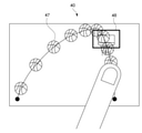
- FIG. 6 is a schematic diagram showing an example of setting the frame rate region and the frame rate of the image when the rehearsal image was acquired.
- the control GUI 40 when the rehearsal image is acquired is taken as an example.
- the basketball 47 is ghost-displayed based on the expected route and frame rate input by the user.
- the ghost display indicates that a state in which a specific subject moves over a plurality of frames is virtually displayed according to an expected path which is a frame area and a set frame rate. For example, when ghosts are displayed overlapping, it indicates that the movement is slow, and when they are displayed at intervals, it indicates that the movement is fast. For example, in FIG. 5, since the ghosts of the basketball 47 near the goal 48 are displayed overlapping, the frame rate of the image is controlled to be small when the basketball 47 is near the goal 48.
- FIG. 7 is a schematic diagram showing an example of the control GUI 50 for controlling the frame rate.
- the control GUI 50 displays a graph showing the frame rate on the vertical axis and the length from the start point on the horizontal axis.
- the user can adjust the frame rate in the frame rate region via the control GUI 50.
- the solid line 53 connecting the start point 51 to the end point 52 indicates the frame rate in the predicted route 43 from the start point 44 to the end point 45 input via the control GUI 40 shown in FIG.
- the dotted line 54 connecting the start point 51 and the end point 52 indicates a range in which the frame rate in the image can be changed. That is, the user can adjust the frame rate so as not to exceed the dotted line displayed on the control GUI 50.
- the frame rate indicated by the dotted line 54 is calculated based on the actual speed of the specific subject recognized by the recognition unit 17. For example, it may be calculated based on the actual speed of a specific subject at the time of shooting. Further, for example, it may be calculated based on the speed of a specific subject in the rehearsal image.
- the frame rate indicated by the dotted line 54 can be obtained by the above (Equation 1).
- the speed of the specific subject detected in advance by the recognition unit 17 in the rehearsal image is used as the predicted value of Vnow, which is the actual speed of the specific subject.
- the dotted line 54 corresponding to the frame rate obtained by this is displayed on the control GUI 50.
- control GUI 50 presents to the user when there is a rehearsal image and the solid line 53 exceeds the dotted line 54.
- the text may be presented to the user or may be presented by voice.
- control GUI 50 displays a marker 55 indicating the position of a specific subject on the predicted path. That is, the user can adjust the frame rate of a specific subject at the current position of the marker 55.
- control GUI 50 has a frame rate region and an image display unit 56 for displaying a specific subject.
- the image display unit 56 displays the predicted route 43 set by the control GUI 40 and the position (marker 55) of a specific subject passing through the predicted route. As a result, the user can control the frame rate of a specific subject at each position of the predicted path while simultaneously viewing the marker 55 on the predicted path and the graph. Further, the rehearsal image may be displayed on the image display unit 56.
- the determination unit 24 determines whether or not the distance between the specific subject and the frame rate region is equal to or less than the threshold value (step 104).
- the frame rate of the image is not controlled until the distance between the specific subject and the frame rate region is equal to or less than the threshold value.
- the recognition unit 17 recognizes the position of a specific subject and the frame rate at the position.
- the image sensor 13 is controlled by the control unit 15, and all images are captured at a high frame rate number.
- the shooting control unit 25 or the reproduction control unit 26 controls the frame rate of the image by performing a process of thinning out frames by using a conversion process or the like.
- the frame rate of the image may be controlled by adding frames by the shooting control unit 25 or the reproduction control unit 26 using an addition process or the like.
- the frame rate of the image may be controlled by performing a process of synthesizing the image or the like. Specifically, when the frame rate of an image is controlled in real time during shooting, the time interval for shooting each image for each frame is changed one after another by the shooting control unit 25.
- the control unit 15 can control the image sensor 13 to shoot at a set frame rate.
- the reproduction control unit 26 executes thinning and addition processing, so that the image is reproduced at the frame rate at the time of reproduction set in the frame rate setting unit 23.
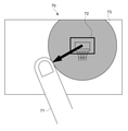
- FIG. 8 is a schematic diagram showing an example of the shape of the frame rate region.
- the user sets a circular frame rate region via the control GUI 70.
- the user can set the frame rate region by touching an arbitrary point and sliding the finger 71 (moving the finger in the touched state). For example, by touching the goal 72 and sliding the finger in a predetermined direction, a circular frame rate region 73 having a radius of the distance moved by the finger is set.
- FIG. 9 is a schematic diagram showing another example of the shape of the frame rate region.
- the entire stadium is photographed at a wide angle by the image pickup device 10.
- the user sets a rectangular frame rate region via the control GUI 70.
- the user can set the frame rate area by touching a predetermined position and sliding the finger 74.
- a rectangular frame rate region 75 having a diagonal line of the distance moved by the finger is set.
- the user can set the center coordinates of the set frame rate region 75. If not set by the user, the center coordinates of the frame rate region 75 are set to the center of gravity of the frame rate region. Further, in the case of the circular frame rate region 73, the center coordinates (any touched point) are set to the center.
- the method of setting the frame rate area is not limited.
- the coordinates and radius may be input numerically.
- the shape (boundary) of the frame rate region may be set by the user by tracing it with a finger.
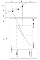
- FIG. 10 is a schematic diagram showing an example of a frame rate control GUI in a frame rate region.
- a graph showing control of the frame rate in the frame rate region and a predicted route 81 corresponding to the graph are displayed on the control GUI 80.
- control unit 15 controls the frame rate of the image based on the position of the specific subject determined by the determination unit 24 and the position of the center coordinate 83 set in the frame rate area 82. .. Further, the user can control the frame rate corresponding to the path from the boundary of the frame rate region 82 to the center coordinate 83 of the frame rate region via the control GUI 80.
- the frame rate of the image is controlled so that the frame rate increases as the specific subject approaches the center coordinates from the boundary of the frame rate region.
- the normal frame rate is the normal frame rate when the image is reproduced. For example, when the image is reproduced at a frame rate number of 60, the frame rate number 60 is the normal frame rate.
- the user can use the control GUI 80 to determine the magnitude of the frame rate near the boundary of the frame rate region 82, the ratio of the distance from the boundary to the center coordinate 83 and the increase (decrease) of the frame rate, and the frame rate at the center coordinate 83. Set the size of.
- the frame rate at the position 84 (85) where the ratio of the distance between the center coordinate 83 and the frame rate region 82 is the same is set to be the same, one graph is displayed for the frame rate region 82. Will be done. That is, if the frame rate settings are different between the route 81 from the boundary of the frame rate region 82 to the center coordinate 83 and the route 87 from the center coordinate 83 to the boundary of the frame rate region 82, the two graphs are displayed. Is displayed.
- the method of controlling the frame rate is not limited. For example, the methods shown in FIGS. 11, 12, 13, and 14 described later may be used.
- 11 to 14 are schematic views showing an example of frame rate control.
- the vertical axis shows the frame rate and the horizontal axis shows the distance from the starting point.
- the determination unit 24 determines whether or not a specific subject has crossed the boundary of the frame rate region. For example, the determination unit 24 determines whether or not the center of gravity of a specific subject exceeds the frame rate region. When the center of gravity of a specific subject exceeds the frame rate region, the control unit 15 changes the frame rate to the frame rate shown in FIG.
- the frame rate of the image is changed stepwise as the specific subject approaches the center coordinates of the frame rate region.
- the frame rate is set so that the frame rate gradually increases as a specific subject approaches the center coordinates.
- the frame rate may be set so that the frame rate of the image gradually decreases as the specific subject moves away from the center coordinates.
- the user may be able to control at what stage the frame rate approaches the set value via the control GUI, or may be appropriately calculated by the control unit 15.
- the relationship between the distance and the frame rate as shown in FIG. 12 is recorded in advance in the recording unit 16 as a table, and the control unit 15 may control the frame rate of the image based on the table.
- the frame rate of the image is continuously changed as the specific subject approaches the center coordinates of the frame rate region.
- the frame rate is set so that the slope of the straight line becomes steeper as the specific subject approaches the center coordinates.
- the frame rate is set so that the inclination of the straight line becomes gentle as the specific subject moves away from the center coordinates.
- the user can control via the control GUI so that the slope of the straight line and the curve when approaching the value of the set frame rate becomes high or low. That is, the coefficients of the straight line or the curve are changed.
- the relationship between the distance and the frame rate as shown in FIG. 13 is recorded in advance in the recording unit 16 as a table, and the control unit 15 may control the frame rate of the image based on the table.
- the image pickup apparatus 10 recognizes a specific subject in the image. It is determined whether or not the distance between the recognized specific subject and the frame rate region for setting the frame rate of the image is equal to or less than the threshold value. This makes it possible to easily control the frame rate of the image.
- a method such as the RAMP effect that gradually changes the frame rate of a moving image for a scene that is desired to be impressed as a video expression may be used.
- a scene to be shot is determined in advance, rehearsals and the like are performed, and a target frame rate and a time until the frame rate is reached are set. In this case, it is difficult to shoot the desired moving image because the timing is accurately adjusted with respect to the movement of the object.
- the user can input the frame rate of a specific subject by tracing it along the expected path. This makes it easier to shoot, play, and edit images with more intuitive input than before.
- the image pickup apparatus 10 controls the frame rate of the image at the time of shooting and at the time of reproduction.
- the captured image may be transmitted to an external information processing device, and the frame rate of the image may be controlled by the information processing device.
- FIG. 15 is a block diagram showing a functional configuration example of the information processing apparatus.
- the information processing apparatus 100 includes a control unit 15, a recording unit 16, a recognition unit 17, a display unit 18, an output unit 19, and an operation unit 20.
- the information processing device 100 includes an editing device such as a PC or a smartphone, and a playback device such as a monitor.
- an image signal may be supplied by the image pickup device 10 and the frame rate may be controlled for the image signal.
- a signal for controlling the frame rate set by the editing device may be supplied to the playback device, and the playback device may control the frame rate according to the signal. Since each block executes the same processing as the block mounted on the image pickup apparatus 10, the description thereof will be omitted.
- the information processing device 100 is wirelessly or wiredly connected to the image pickup device 10 that captures an image via the output unit 19.
- the connection form between each device is not limited, and for example, wireless LAN communication such as WiFi and short-range wireless communication such as Bluetooth (registered trademark) can be used.
- the captured image signal or the reproduced image signal may be received from the image pickup apparatus 10 and the frame rate of the image signal received by the information processing apparatus 100 may be controlled.
- a reproduced image signal recorded in a recording device such as an SD (Secure Digital) card may be read.
- control the frame rate of the captured image signal or the reproduced image signal it is possible to control the frame rate of the captured image signal or the reproduced image signal.
- the control unit 15 performs frame rate thinning and addition processing on the recorded image, so that the image is reproduced at the set frame rate.
- a captured image or a reproduced image whose frame rate is controlled by the image pickup device 10 or the information processing device 100 may be displayed on the display unit of the external device.
- the frame rate is controlled according to the distance between a specific subject and the frame rate region.
- interpolation processing may be performed when the actual position during shooting of a specific subject and the position of the frame rate region deviate from each other.
- the interpolation process may be performed when the actual movement (path) of a specific subject during shooting and the path (expected path) of the set frame rate region deviate from each other.
- the control unit 15 uses nearest interpolation, secondary interpolation, etc., and the frame rate of the image. May be controlled.
- the frame rate of the image is controlled from the speed of a specific subject input by the user's finger.
- the user may enter a numerical value of the frame rate of the image without being limited to this.
- the image was taken and reproduced according to the set frame rate of the image. Not limited to this, the following calculation may be executed when the actual shooting and reproduction cannot be performed according to the frame rate set by the user.
- the frame rate is input according to the speed at which the user's finger moves.
- a button or the like on which the numerical value can be arbitrarily changed may be displayed on the control GUI.
- only one frame rate region is set.
- a plurality of frame rate areas may be set.
- a frame rate region containing two basket goals may be set.
- the control unit 15 may control the frame rate of the image based on the frame rate at which the specific subject is closer to the center coordinates of the frame rate region when the plurality of frame rate regions overlap.
- the control unit 15 may take a weighted average of the frame rates based on the distances between the center coordinates of the plurality of frame rate regions and a specific subject.
- the frame rate is controlled for sports such as basketball. Not limited to this, it may be used in any field.
- the wedding cake may be included in the frame rate area and controlled to be the set frame rate when a person approaches to cut the cake.
- FIG. 16 is a block diagram showing a hardware configuration example of the information processing apparatus 100.
- the information processing apparatus 100 includes a CPU 101, a ROM 102, a RAM 103, an input / output interface 105, and a bus 104 connecting these to each other.
- a display unit 106, an input unit 107, a storage unit 108, a communication unit 109, a drive unit 110, and the like are connected to the input / output interface 105.
- the display unit 106 is a display device using, for example, a liquid crystal display, an EL, or the like.
- the input unit 107 is, for example, a keyboard, a pointing device, a touch panel, or other operating device. When the input unit 107 includes a touch panel, the touch panel may be integrated with the display unit 106.
- the storage unit 108 is a non-volatile storage device, for example, an HDD, a flash memory, or other solid-state memory.
- the drive unit 110 is a device capable of driving a removable recording medium 111 such as an optical recording medium or a magnetic recording tape.
- the communication unit 109 is a modem, router, or other communication device for communicating with other devices that can be connected to a LAN, WAN, or the like.
- the communication unit 109 may communicate using either wired or wireless.
- the communication unit 109 is often used separately from the information processing device 100.
- Information processing by the information processing apparatus 100 having the hardware configuration as described above is realized by the cooperation between the software stored in the storage unit 108 or the ROM 102 or the like and the hardware resources of the information processing apparatus 100.
- the information processing method according to the present technology is realized by loading the program constituting the software stored in the ROM 102 or the like into the RAM 103 and executing the program.
- the program is installed in the information processing apparatus 100 via, for example, the recording medium 111.
- the program may be installed in the information processing apparatus 100 via a global network or the like.
- any non-transient storage medium that can be read by a computer may be used.
- An information processing device By linking a computer mounted on a communication terminal with another computer capable of communicating via a network or the like, an image pickup device, an information processing device, an information processing method, and a program related to this technology are executed, and related to this technology.
- An information processing device may be constructed.
- the image pickup device, the information processing device, the information processing method, and the program according to the present technology can be executed not only in a computer system composed of a single computer but also in a computer system in which a plurality of computers operate in conjunction with each other. ..
- the system means a set of a plurality of components (devices, modules (parts), etc.), and it does not matter whether or not all the components are in the same housing. Therefore, a plurality of devices housed in separate housings and connected via a network, and one device in which a plurality of modules are housed in one housing are both systems.
- the computer system executes the image pickup device, information processing device, information processing method, and program related to this technology, for example, recognition of a specific subject, frame rate setting, frame rate control, and the like are executed by a single computer. Includes both when it is done and when each process is performed by a different computer. Further, the execution of each process by a predetermined computer includes having another computer execute a part or all of the process and acquiring the result.
- the image pickup device, information processing device, information processing method, and program related to this technology can be applied to the configuration of cloud computing in which one function is shared by a plurality of devices via a network and jointly processed. It is possible.
- Each configuration of the frame rate area setting unit 22, the determination unit 24, the frame rate setting unit 23, etc., the control flow of the communication system, etc. described with reference to each drawing is merely an embodiment and does not deviate from the purpose of the present technology. It can be deformed arbitrarily within the range. That is, other arbitrary configurations, algorithms, and the like for implementing the present technology may be adopted.
- the effects described in the present disclosure are merely examples and are not limited, and other effects may be obtained.
- the description of the plurality of effects described above does not necessarily mean that the effects are exerted at the same time. It means that at least one of the above-mentioned effects can be obtained depending on the conditions and the like, and of course, there is a possibility that an effect not described in the present disclosure may be exhibited.
- this technology can also adopt the following configurations.
- a recognition unit that recognizes a specific subject in an image An image pickup apparatus including a determination unit for determining whether or not the distance between the recognized specific subject and a frame rate region for setting a frame rate of an image is equal to or less than a threshold value.
- An image pickup apparatus including a frame rate setting unit for setting the frame rate of the image.
- An image pickup device provided with a shooting control unit.
- the image pickup apparatus according to (2) further When the determination unit determines that the distance between the specific subject and the set frame rate region is equal to or less than the threshold value, the determination unit controls the image to be reproduced at the set frame rate.
- An image pickup device provided with a playback control unit.
- the frame rate area setting unit is an image pickup device that sets the frame rate area as a point.
- the frame rate area setting unit is an image pickup device that sets the frame rate area as a line.
- the frame rate area setting unit is an image pickup device that sets the frame rate area as a region having a predetermined range.
- the image pickup apparatus sets a plurality of the frame rate areas and sets the frame rate area.
- the shooting control unit determines the set frame rate.
- the image pickup apparatus sets a plurality of the frame rate areas and sets the frame rate area.
- the reproduction control unit determines the set frame rate.
- An image pickup device that controls the reproduction of the image.
- the image pickup apparatus (11) The image pickup apparatus according to (4).
- the frame rate area setting unit sets the frame rate area as an area having a predetermined range, and sets the frame rate area as an area.
- the shooting control unit controls to shoot the image at the set frame rate when the determination unit determines that the specific subject is within the range of the set frame rate region.
- Imaging device. (12) The image pickup apparatus according to (5).
- the frame rate area setting unit sets the frame rate area as an area having a predetermined range, and sets the frame rate area as an area.
- the reproduction control unit controls to reproduce the image at the set frame rate when the determination unit determines that the specific subject is within the range of the set frame rate region.
- Imaging device (12) The image pickup apparatus according to (5).
- the frame rate area setting unit sets the frame rate area as an area having a predetermined range, and sets the frame rate area as an area.
- the reproduction control unit controls to reproduce the image at the set frame rate when the determination unit determines that the specific subject is within the range of the set frame rate
- the image pickup apparatus according to (2), further Equipped with an operation unit that accepts user operations The frame rate area setting unit is an image pickup device that sets the frame rate area according to a user's operation on the operation unit.
- the image pickup apparatus according to (3), further Equipped with an operation unit that accepts user operations The frame rate setting unit is an image pickup device that sets the frame rate of the image according to the user's operation on the operation unit.
- the frame rate setting unit is an image pickup device that sets the frame rate so that the frame rate changes stepwise according to the distance between the specific subject and the frame rate region. (16) The image pickup apparatus according to (3).
- the frame rate setting unit is an image pickup device that sets the frame rate so that the frame rate changes continuously according to the distance between the specific subject and the frame rate region.
- a recognition unit that recognizes a specific subject in an image
- An information processing device including a determination unit for determining whether or not the distance between the recognized specific subject and the frame rate region for setting the frame rate of an image is equal to or less than a threshold value.
- a step of recognizing a specific subject in an image A program that causes a computer system to perform a step of determining whether or not the distance between the recognized specific subject and the frame rate area for setting the frame rate of an image is equal to or less than a threshold value.
Abstract
[Problem] To provide: an imaging device capable of more easily controlling a frame rate of an image; an information processing device; an information processing method; and a program. [Solution] To solve the problem, the imaging device according to an embodiment of the present technology comprises a recognition unit and a determination unit. The recognition unit recognizes a particular subject in an image. The determination unit determines whether the distance between the recognized particular subject and a frame rate region for setting a frame rate of the image is equal to or less than a threshold. Accordingly, it is possible to easily control the frame rate of the image when capturing, reproducing, and editing the image by an intuitive input compared to conventional technology.
Description
本技術は、動画編集等に適用可能な撮像装置、情報処理装置、情報処理方法、及びプログラムに関する。
This technology relates to an image pickup device, an information processing device, an information processing method, and a program applicable to video editing and the like.
特許文献1に記載の画像再生装置では、動画像上における複数の特定物体間の距離、又は固定位置と注目物体間の距離とに応じて、動画像の再生速度が制御される。これにより、重要なシーンに対する再生速度の適切化に寄与するように図られている(特許文献1の段落[0039][0051]図3等)。
In the image reproduction device described in Patent Document 1, the reproduction speed of the moving image is controlled according to the distance between a plurality of specific objects on the moving image or the distance between the fixed position and the object of interest. This is designed to contribute to the optimization of the reproduction speed for important scenes (paragraphs [0039] [0051] FIG. 3 of Patent Document 1 and the like).
特許文献1のように動画像の特定のシーンを印象づけるために、動画のフレームレートを変化させる手法が用いられることがある。このように、画像のフレームレートを容易に制御することを可能とする技術が求められている。
As in Patent Document 1, a method of changing the frame rate of a moving image may be used in order to impress a specific scene of a moving image. As described above, there is a demand for a technique that makes it possible to easily control the frame rate of an image.
以上のような事情に鑑み、本技術の目的は、画像のフレームレートをより容易に制御することが可能な撮像装置、情報処理装置、情報処理方法、及びプログラムを提供することにある。
In view of the above circumstances, an object of the present technology is to provide an image pickup device, an information processing device, an information processing method, and a program capable of more easily controlling the frame rate of an image.
上記目的を達成するため、本技術の一形態に係る撮像装置は、認識部、及び判定部を具備する。
前記認識部は、画像内の特定の被写体を認識する。
前記判定部は、認識された前記特定の被写体と、画像のフレームレートを設定するためのフレームレート領域との間の距離が閾値以下か否かを判定する。 In order to achieve the above object, the image pickup apparatus according to one embodiment of the present technology includes a recognition unit and a determination unit.
The recognition unit recognizes a specific subject in the image.
The determination unit determines whether or not the distance between the recognized specific subject and the frame rate region for setting the frame rate of the image is equal to or less than the threshold value.
この撮像装置では、画像内の特定の被写体が認識される。認識された前記特定の被写体と、画像のフレームレートを設定するためのフレームレート領域との間の距離が閾値以下か否かが判定される。これにより、画像のフレームレートを容易に制御することが可能となる。
This image pickup device recognizes a specific subject in the image. It is determined whether or not the distance between the recognized specific subject and the frame rate region for setting the frame rate of the image is equal to or less than the threshold value. This makes it possible to easily control the frame rate of the image.
前記撮像装置は、さらに、前記フレームレート領域を設定するフレームレート領域設定部を具備してもよい。
The image pickup device may further include a frame rate area setting unit for setting the frame rate area.
前記撮像装置は、さらに、前記画像のフレームレートを設定するフレームレート設定部を具備してもよい。
The image pickup device may further include a frame rate setting unit for setting the frame rate of the image.
前記撮像装置は、さらに、前記判定部により、前記特定の被写体と前記設定されたフレームレート領域との間の距離が閾値以下であると判定された場合に、前記設定されたフレームレートで前記画像を撮影するように制御する撮影制御部を具備してもよい。
Further, when the determination unit determines that the distance between the specific subject and the set frame rate region is equal to or less than the threshold value, the image pickup apparatus further determines the image at the set frame rate. An imaging control unit may be provided for controlling the imaging.
前記撮像装置は、さらに、前記判定部により、前記特定の被写体と前記設定されたフレームレート領域との間の距離が閾値以下であると判定された場合に、前記設定されたフレームレートで前記画像を再生するように制御する再生制御部を具備してもよい。
Further, when the determination unit determines that the distance between the specific subject and the set frame rate region is equal to or less than the threshold value, the image pickup apparatus further determines the image at the set frame rate. It may be provided with a reproduction control unit which controls to reproduce.
前記フレームレート領域設定部は、前記フレームレート領域を点として設定してもよい。
The frame rate area setting unit may set the frame rate area as a point.
前記フレームレート領域設定部は、前記フレームレート領域を線として設定してもよい。
The frame rate area setting unit may set the frame rate area as a line.
前記フレームレート領域設定部は、前記フレームレート領域を所定の範囲を持つ領域として設定してもよい。
The frame rate area setting unit may set the frame rate area as an area having a predetermined range.
前記フレームレート領域設定部は、複数の前記フレームレート領域を設定してもよい。この場合、前記撮影制御部は、前記判定部により、前記特定の被写体と前記設定された複数のフレームレート領域のそれぞれとの間の距離が閾値以下であると判定された場合に、前記設定されたフレームレートで前記画像を撮影するよう制御してもよい。
The frame rate area setting unit may set a plurality of the frame rate areas. In this case, the shooting control unit is set when the determination unit determines that the distance between the specific subject and each of the set plurality of frame rate regions is equal to or less than a threshold value. The image may be controlled to be taken at a different frame rate.
前記フレームレート領域設定部は、複数の前記フレームレート領域を設定してもよい。この場合、前記再生制御部は、前記判定部により、前記特定の被写体と前記設定された複数のフレームレート領域のそれぞれとの間の距離が閾値以下であると判定された場合に、前記設定されたフレームレートで前記画像を再生するよう制御してもよい。
The frame rate area setting unit may set a plurality of the frame rate areas. In this case, the reproduction control unit is set when the determination unit determines that the distance between the specific subject and each of the set plurality of frame rate regions is equal to or less than a threshold value. The image may be controlled to be reproduced at a different frame rate.
前記フレームレート領域設定部は、前記フレームレート領域を所定の範囲を持つ領域として設定してもよい。この場合、前記撮影制御部は、前記判定部により、前記特定の被写体が前記設定されたフレームレート領域の範囲内にあると判定された場合に、前記設定されたフレームレートで前記画像を撮影するよう制御してもよい。
The frame rate area setting unit may set the frame rate area as an area having a predetermined range. In this case, when the determination unit determines that the specific subject is within the range of the set frame rate region, the imaging control unit captures the image at the set frame rate. It may be controlled as such.
前記フレームレート領域設定部は、前記フレームレート領域を所定の範囲を持つ領域として設定してもよい。この場合、前記再生制御部は、前記判定部により、前記特定の被写体が前記設定されたフレームレート領域の範囲内にあると判定された場合に、前記設定されたフレームレートで前記画像を再生するよう制御してもよい。
The frame rate area setting unit may set the frame rate area as an area having a predetermined range. In this case, when the determination unit determines that the specific subject is within the range of the set frame rate region, the reproduction control unit reproduces the image at the set frame rate. It may be controlled as such.
前記撮像装置は、さらに、ユーザの操作を受け付ける操作部を具備してもよい。この場合、前記フレームレート領域設定部は、前記操作部に対するユーザの操作に応じて、前記フレームレート領域を設定してもよい。
The image pickup device may further include an operation unit that accepts user operations. In this case, the frame rate area setting unit may set the frame rate area according to the user's operation on the operation unit.
前記撮像装置は、さらに、ユーザの操作を受け付ける操作部を具備してもよい。この場合、前記フレームレート設定部は、前記操作部に対するユーザの操作に応じて、前記画像のフレームレートを設定してもよい。
The image pickup device may further include an operation unit that accepts user operations. In this case, the frame rate setting unit may set the frame rate of the image according to the user's operation on the operation unit.
前記フレームレート設定部は、前記特定の被写体と前記フレームレート領域との間の距離に応じて、段階的にフレームレートが変わるよう前記フレームレートを設定してもよい。
The frame rate setting unit may set the frame rate so that the frame rate changes stepwise according to the distance between the specific subject and the frame rate region.
前記フレームレート設定部は、前記特定の被写体と前記フレームレート領域との間の距離に応じて、連続的にフレームレートが変わるよう前記フレームレートを設定してもよい。
The frame rate setting unit may set the frame rate so that the frame rate changes continuously according to the distance between the specific subject and the frame rate region.
本技術の一形態に係る情報処理装置は、認識部、及び判定部を具備する。
前記認識部は、画像内の特定の被写体を認識する。
前記判定部は、認識された前記特定の被写体と、画像のフレームレートを設定するためのフレームレート領域との間の距離が閾値以下か否かを判定する。 The information processing device according to one embodiment of the present technology includes a recognition unit and a determination unit.
The recognition unit recognizes a specific subject in the image.
The determination unit determines whether or not the distance between the recognized specific subject and the frame rate region for setting the frame rate of the image is equal to or less than the threshold value.
本技術の一形態に係る情報処理方法は、コンピュータシステムが実行する情報処理方法であって、画像内の特定の被写体を認識することを含む。
認識された前記特定の被写体と、画像のフレームレートを設定するためのフレームレート領域との間の距離が閾値以下か否かが判定される。 The information processing method according to one embodiment of the present technology is an information processing method executed by a computer system and includes recognizing a specific subject in an image.
It is determined whether or not the distance between the recognized specific subject and the frame rate region for setting the frame rate of the image is equal to or less than the threshold value.
本技術の一形態に係るプログラムは、コンピュータシステムに以下のステップを実行させる。
画像内の特定の被写体を認識するステップ。
認識された前記特定の被写体と、画像のフレームレートを設定するためのフレームレート領域との間の距離が閾値以下か否かを判定するステップ。 A program according to an embodiment of the present technology causes a computer system to perform the following steps.
The step of recognizing a specific subject in an image.
A step of determining whether or not the distance between the recognized specific subject and the frame rate region for setting the frame rate of the image is equal to or less than the threshold value.
以下、本技術に係る実施形態を、図面を参照しながら説明する。
Hereinafter, embodiments relating to this technology will be described with reference to the drawings.
[撮像装置]
図1は、本技術に係る撮像装置の概要を説明するための模式図である。 [Image pickup device]
FIG. 1 is a schematic diagram for explaining an outline of an image pickup apparatus according to the present technology.
図1は、本技術に係る撮像装置の概要を説明するための模式図である。 [Image pickup device]
FIG. 1 is a schematic diagram for explaining an outline of an image pickup apparatus according to the present technology.
撮像装置10は、撮像素子13(イメージセンサ)、図示されない光学系11や絞り等を有し、画角内の撮影が可能である。本実施形態では、撮像装置10は、バスケットボール1をゴール2に向けてシュートしている人物3を撮影している。
なお、撮像装置の有する構成は限定されない。例えば、撮像素子13として、CMOS(Complementary Metal-Oxide Semiconductor)センサやCCD(Charge Coupled Device)センサ等のイメージセンサが用いられてもよい。 Theimage pickup device 10 has an image pickup element 13 (image sensor), an optical system 11 (not shown), an aperture, and the like, and can take pictures within the angle of view. In the present embodiment, the image pickup apparatus 10 photographs a person 3 who is shooting a basketball 1 toward a goal 2.
The configuration of the image pickup device is not limited. For example, as theimage pickup device 13, an image sensor such as a CMOS (Complementary Metal-Oxide Semiconductor) sensor or a CCD (Charge Coupled Device) sensor may be used.
なお、撮像装置の有する構成は限定されない。例えば、撮像素子13として、CMOS(Complementary Metal-Oxide Semiconductor)センサやCCD(Charge Coupled Device)センサ等のイメージセンサが用いられてもよい。 The
The configuration of the image pickup device is not limited. For example, as the
また撮像装置10は、撮像装置10は、画像内の特定の被写体を認識し、該特定の被写体と画像のフレームレートを設定するためのフレームレート領域との間の距離が閾値以下か否かを判定する。
例えば、特定の被写体としてバスケットボール1と、ゴール2を含むフレームレート領域との間の距離が閾値以下になった場合に、画像のフレームレートが制御される。すなわち、特定の被写体とフレームレート領域との距離に応じて、画像のフレームレートが制御される。
フレームレート領域は、点、線、及び所定の範囲を持った領域を含み、画像内の特定の位置に予め設定された領域である。
特定の被写体とは、画像内に含まれる被写体のうち、後述する認識部17により認識された被写体である。
なお、画像とは、撮影画像と再生画像とが含まれる。 Further, theimage pickup device 10 recognizes a specific subject in the image, and determines whether or not the distance between the specific subject and the frame rate region for setting the frame rate of the image is equal to or less than the threshold value. judge.
For example, when the distance between thebasketball 1 as a specific subject and the frame rate region including the goal 2 becomes equal to or less than a threshold value, the frame rate of the image is controlled. That is, the frame rate of the image is controlled according to the distance between the specific subject and the frame rate region.
The frame rate region includes points, lines, and regions having a predetermined range, and is a region preset at a specific position in the image.
The specific subject is a subject recognized by therecognition unit 17, which will be described later, among the subjects included in the image.
The image includes a photographed image and a reproduced image.
例えば、特定の被写体としてバスケットボール1と、ゴール2を含むフレームレート領域との間の距離が閾値以下になった場合に、画像のフレームレートが制御される。すなわち、特定の被写体とフレームレート領域との距離に応じて、画像のフレームレートが制御される。
フレームレート領域は、点、線、及び所定の範囲を持った領域を含み、画像内の特定の位置に予め設定された領域である。
特定の被写体とは、画像内に含まれる被写体のうち、後述する認識部17により認識された被写体である。
なお、画像とは、撮影画像と再生画像とが含まれる。 Further, the
For example, when the distance between the
The frame rate region includes points, lines, and regions having a predetermined range, and is a region preset at a specific position in the image.
The specific subject is a subject recognized by the
The image includes a photographed image and a reproduced image.
また撮像装置10は、画像のフレームレート領域を設定する。例えば、ユーザの入力に応じて、フレームレート領域として、ある程度範囲を持った領域が指定されてもよいし、線や点として指定されてもよい。図1を例とすると、バスケットボール1がゴール2に入るまでの経路(軌跡)がフレームレート領域として設定されてもよい。また例えば、ゴール2を中心に矩形状の領域がフレームレート領域として設定されてもよい。なお、フレームレート領域の形状や面積は限定されない。
Further, the image pickup apparatus 10 sets a frame rate region of the image. For example, a region having a certain range may be designated as the frame rate region, or may be designated as a line or a point according to the input of the user. Taking FIG. 1 as an example, the route (trajectory) until the basketball 1 enters the goal 2 may be set as the frame rate region. Further, for example, a rectangular region centered on the goal 2 may be set as a frame rate region. The shape and area of the frame rate region are not limited.
また撮像装置10は、画像のフレームレートを制御する。本実施形態では、撮像装置10は、撮影時及び再生時における画像のフレームレートを制御する。
例えば、撮像装置10は、特定の被写体と設定されたフレームレート領域との間の距離が閾値以下であると判定された場合に、設定されたフレームレートで画像を撮影又は再生するように制御する。 Theimage pickup device 10 also controls the frame rate of the image. In the present embodiment, the image pickup apparatus 10 controls the frame rate of the image during shooting and reproduction.
For example, theimage pickup apparatus 10 controls to capture or reproduce an image at a set frame rate when it is determined that the distance between a specific subject and a set frame rate region is equal to or less than a threshold value. ..
例えば、撮像装置10は、特定の被写体と設定されたフレームレート領域との間の距離が閾値以下であると判定された場合に、設定されたフレームレートで画像を撮影又は再生するように制御する。 The
For example, the
図2は、撮像装置10の機能的な構成例を示すブロック図である。
図2に示すように、撮像装置10は、光学系11、駆動部12、撮像素子13、信号処理部14、制御部15、記録部16、認識部17、表示部18、出力部19、及び操作部20を有する。 FIG. 2 is a block diagram showing a functional configuration example of theimage pickup apparatus 10.
As shown in FIG. 2, theimage pickup apparatus 10 includes an optical system 11, a drive unit 12, an image pickup element 13, a signal processing unit 14, a control unit 15, a recording unit 16, a recognition unit 17, a display unit 18, an output unit 19, and an image pickup device 10. It has an operation unit 20.
図2に示すように、撮像装置10は、光学系11、駆動部12、撮像素子13、信号処理部14、制御部15、記録部16、認識部17、表示部18、出力部19、及び操作部20を有する。 FIG. 2 is a block diagram showing a functional configuration example of the
As shown in FIG. 2, the
光学系11は、レンズや絞り機構、シャッタ等で構成される。例えば、光学系11は、入射端レンズ、ズームレンズ、フォーカスレンズ、集光レンズなどの各種レンズが用いられてもよい。また例えば、信号電荷が飽和せずにダイナミックレンジ内に入っている状態でセンシングが行われるようにレンズやアイリス(絞り)による開口量などを調整することで露光制御を行う絞り機構や、フォーカルプレーンシャッタなどのシャッタユニットが用いられてもよい。
The optical system 11 is composed of a lens, an aperture mechanism, a shutter, and the like. For example, as the optical system 11, various lenses such as an incident end lens, a zoom lens, a focus lens, and a condenser lens may be used. Also, for example, an aperture mechanism that controls exposure by adjusting the aperture amount of a lens or iris (aperture) so that sensing is performed while the signal charge is not saturated and is within the dynamic range, or a focal plane. A shutter unit such as a shutter may be used.
駆動部12は、光学系11に含まれるレンズ等を駆動する。
The drive unit 12 drives a lens or the like included in the optical system 11.
撮像素子13は、光学系11を介して入射された被写体からの光について露光制御を行う。また撮像素子13は、画素で光電変換した電気信号について、例えばCDS処理やAGS処理やA/D変換処理を行う処理部を備えて構成される。
本実施形態では、デジタルデータとしての撮影画像信号が信号処理部14及び制御部15に出力される。 Theimage pickup device 13 controls the exposure of the light from the subject incident through the optical system 11. Further, the image pickup device 13 is configured to include a processing unit that performs, for example, CDS processing, AGS processing, or A / D conversion processing on the electric signal photoelectrically converted by the pixels.
In the present embodiment, the captured image signal as digital data is output to thesignal processing unit 14 and the control unit 15.
本実施形態では、デジタルデータとしての撮影画像信号が信号処理部14及び制御部15に出力される。 The
In the present embodiment, the captured image signal as digital data is output to the
信号処理部14は、例えば、DSP(Digital Signal Processor)などのデジタル信号処理に特化したマイクロプロセッサや、マイクロコンピュータなどにより構成される。信号処理部14は、撮像素子13から送られてくるデジタル信号(撮像画像信号)に対して、各種の信号処理を施す。具体的には、R,G,Bの色チャンネル間の補正処理、ホワイトバランス補正、収差補正、シェーディング補正等の処理を行う。また、信号処理部14は、R,G,Bの画像データから、輝度(Y)信号及び色(C)信号を生成(分離)するYC生成処理や、輝度や色を調整する処理、ニー補正やガンマ補正などの各処理を行う。信号処理部14は、各種の信号処理を施した画像信号を認識部や制御部に出力する。更に、信号処理部14は、解像度変換処理や記録用や通信用のための符号化を行うコーデック処理などを行うことによって最終的な出力形式への変換を行う。最終的な出力形式へ変換された画像信号は、記録部17に記録される。また、画像信号が画像として表示部18に表示される。さらに、外部出力端子から出力されることにより、撮像装置1の外部に設けられたモニタ等の機器に表示される。本実施例における撮影画像信号とは、信号処理部14から出力される画像信号であり、撮影画像として表示部18に表示することでユーザはリアルタイムに撮影中の画像を確認することができる。また、本実施例における再生画像信号とは、記録部16から出力される画像信号であり、再生画像として表示部18に表示することでユーザが記録された画像を確認することができる。
The signal processing unit 14 is composed of, for example, a microprocessor specialized for digital signal processing such as a DSP (Digital Signal Processor), a microcomputer, or the like. The signal processing unit 14 performs various signal processing on the digital signal (image pickup image signal) sent from the image pickup element 13. Specifically, processing such as correction processing between R, G, and B color channels, white balance correction, aberration correction, and shading correction is performed. Further, the signal processing unit 14 generates (separates) a luminance (Y) signal and a color (C) signal from the image data of R, G, and B, a YC generation process, a process of adjusting the luminance and the color, and a knee correction. And each process such as gamma correction. The signal processing unit 14 outputs an image signal subjected to various signal processing to a recognition unit and a control unit. Further, the signal processing unit 14 performs conversion to the final output format by performing resolution conversion processing, codec processing for coding for recording and communication, and the like. The image signal converted into the final output format is recorded in the recording unit 17. Further, the image signal is displayed on the display unit 18 as an image. Further, by outputting from the external output terminal, it is displayed on a device such as a monitor provided outside the image pickup apparatus 1. The captured image signal in this embodiment is an image signal output from the signal processing unit 14, and by displaying the captured image on the display unit 18 as a captured image, the user can confirm the image being captured in real time. Further, the reproduced image signal in this embodiment is an image signal output from the recording unit 16, and the user can confirm the recorded image by displaying it on the display unit 18 as a reproduced image.
制御部15は、CPU(Central Processing Unit)を備えたマイクロコンピュータ(演算処理装置)により構成され、撮像装置10の統括的な制御を行う。例えば、ユーザの操作に応じた信号処理部14における各種信号処理についての指示、撮像動作や記録動作、記録した画像ファイルの再生動作を行う。制御部15は各種撮影モードの切り換え等を行う。各種撮影モードとは、例えば、静止画像撮影モード、動画撮影モード、静止画を連続的に取得する連写モードなどである。制御部15は、これらの機能に対するユーザの操作を可能とするためのユーザインタフェース制御部21(UI制御部21)を備えている。
UI制御部21は、撮像装置10に設けられた各操作子に対する操作を検出する処理や、表示部18に対する表示処理や操作検出処理等を行う。また、制御部15は、光学系11が備える各種のレンズを制御する。例えば、AF制御のための必要な光量を確保するために絞り値を指定する処理や、絞り値に応じた絞り機構の動作指示などを行う。
ROMやフラッシュメモリ等には、制御部15が利用するプログラム等が記憶される。ROMやフラッシュメモリ等には、CPUが各部を制御するためのOS(Operating System)や画像ファイル等のコンテンツファイルの他、各種動作のためのアプリケーションプログラムやファームウェア等が記憶される。制御部15は、当該プログラムを実行することで、撮像装置10全体を制御する。RAMは、制御部15のCPUが実行する各種データ処理の際に用いられるデータやプログラム等が一時的に格納されることにより、制御部15の作業領域として利用される。
また制御部15は、UI制御部21、フレームレート領域設定部22、フレームレート設定部23、判定部24、撮影制御部25、及び再生制御部26を有する。 Thecontrol unit 15 is composed of a microcomputer (arithmetic processing device) equipped with a CPU (Central Processing Unit), and controls the image pickup device 10 in an integrated manner. For example, the signal processing unit 14 gives instructions for various signal processing according to the user's operation, performs an imaging operation, a recording operation, and a reproduction operation of a recorded image file. The control unit 15 switches various shooting modes and the like. The various shooting modes include, for example, a still image shooting mode, a moving image shooting mode, and a continuous shooting mode for continuously acquiring still images. The control unit 15 includes a user interface control unit 21 (UI control unit 21) for enabling a user to operate these functions.
TheUI control unit 21 performs a process of detecting an operation on each operator provided in the image pickup apparatus 10, a display process on the display unit 18, an operation detection process, and the like. Further, the control unit 15 controls various lenses included in the optical system 11. For example, a process of designating an aperture value in order to secure a necessary amount of light for AF control, an operation instruction of an aperture mechanism according to the aperture value, and the like are performed.
A program or the like used by thecontrol unit 15 is stored in the ROM, the flash memory, or the like. In the ROM, flash memory, etc., in addition to content files such as an OS (Operating System) for the CPU to control each part and an image file, application programs and firmware for various operations are stored. The control unit 15 controls the entire image pickup apparatus 10 by executing the program. The RAM is used as a work area of the control unit 15 by temporarily storing data, programs, and the like used in various data processing executed by the CPU of the control unit 15.
Further, thecontrol unit 15 includes a UI control unit 21, a frame rate area setting unit 22, a frame rate setting unit 23, a determination unit 24, a shooting control unit 25, and a reproduction control unit 26.
UI制御部21は、撮像装置10に設けられた各操作子に対する操作を検出する処理や、表示部18に対する表示処理や操作検出処理等を行う。また、制御部15は、光学系11が備える各種のレンズを制御する。例えば、AF制御のための必要な光量を確保するために絞り値を指定する処理や、絞り値に応じた絞り機構の動作指示などを行う。
ROMやフラッシュメモリ等には、制御部15が利用するプログラム等が記憶される。ROMやフラッシュメモリ等には、CPUが各部を制御するためのOS(Operating System)や画像ファイル等のコンテンツファイルの他、各種動作のためのアプリケーションプログラムやファームウェア等が記憶される。制御部15は、当該プログラムを実行することで、撮像装置10全体を制御する。RAMは、制御部15のCPUが実行する各種データ処理の際に用いられるデータやプログラム等が一時的に格納されることにより、制御部15の作業領域として利用される。
また制御部15は、UI制御部21、フレームレート領域設定部22、フレームレート設定部23、判定部24、撮影制御部25、及び再生制御部26を有する。 The
The
A program or the like used by the
Further, the
フレームレート領域設定部22は、フレームレート領域を設定する。例えば、フレームレート領域設定部22は、ユーザの操作に応じて画像内にフレームレート領域を設定する。
The frame rate area setting unit 22 sets the frame rate area. For example, the frame rate area setting unit 22 sets a frame rate area in the image according to the user's operation.
フレームレート設定部23は、画像のフレームレートを設定する。例えば、ユーザにより、特定の被写体と設定されたフレームレート領域とが近づいた場合の、画像のフレームレートが設定される。
The frame rate setting unit 23 sets the frame rate of the image. For example, the user sets the frame rate of an image when a specific subject and a set frame rate area come close to each other.
判定部24は、特定の被写体とフレームレート領域との間の距離が閾値以下か否かを判定する。なお、判定部24により判定される閾値は、予め設定されていてもよいし、ユーザにより設定されていてもよい。
The determination unit 24 determines whether or not the distance between the specific subject and the frame rate region is equal to or less than the threshold value. The threshold value determined by the determination unit 24 may be set in advance or may be set by the user.
撮影制御部25は、判定部24により、特定の被写体とフレームレート領域設定部22により設定されたフレームレート領域との間の距離が閾値以下であると判定された場合に、フレームレート設定部23により設定されたフレームレートで画像を撮影するよう制御する。例えば、特定の被写体とフレームレート領域との間の距離が閾値以下の場合、撮像素子13に対して設定されたフレームレートで画像が撮影されるよう制御される。
When the determination unit 24 determines that the distance between the specific subject and the frame rate area set by the frame rate area setting unit 22 is equal to or less than the threshold value, the shooting control unit 25 determines that the frame rate setting unit 23 Controls to take an image at the frame rate set by. For example, when the distance between the specific subject and the frame rate region is equal to or less than the threshold value, the image is controlled to be captured at the frame rate set for the image sensor 13.
再生制御部26は、判定部24により、特定の被写体とフレームレート領域設定部22により設定されたフレームレート領域との間の距離が閾値以下であると判定された場合に、フレームレート設定部23により設定されたフレームレートで画像を再生するよう制御する。
例えば、画像の再生時にフレームレートを制御する場合、記録部16からの画像信号が再生制御部26に供給され、画像信号が制御部15によりフレームレートの間引きや加算処理が行われ、再生制御部26は、表示部18を制御し、設定された該画像のフレームレートで表示部18に表示又は再生する。
再生時におけるフレームレートの制御も撮影時と同様に、予め高いフレームレート数又は低いフレームレート数で撮影された画像に対して間引き又は加算処理が実行されてもよい。 When thedetermination unit 24 determines that the distance between the specific subject and the frame rate area set by the frame rate area setting unit 22 is equal to or less than the threshold value, the reproduction control unit 26 determines that the frame rate setting unit 23 Controls to play back the image at the frame rate set by.
For example, when controlling the frame rate during image reproduction, the image signal from therecording unit 16 is supplied to the reproduction control unit 26, and the image signal is thinned or added to the frame rate by the control unit 15, and the reproduction control unit is used. 26 controls the display unit 18 and displays or reproduces it on the display unit 18 at a set frame rate of the image.
As for the control of the frame rate at the time of reproduction, the thinning or addition processing may be executed for the images taken in advance with a high frame rate number or a low frame rate number as in the case of shooting.
例えば、画像の再生時にフレームレートを制御する場合、記録部16からの画像信号が再生制御部26に供給され、画像信号が制御部15によりフレームレートの間引きや加算処理が行われ、再生制御部26は、表示部18を制御し、設定された該画像のフレームレートで表示部18に表示又は再生する。
再生時におけるフレームレートの制御も撮影時と同様に、予め高いフレームレート数又は低いフレームレート数で撮影された画像に対して間引き又は加算処理が実行されてもよい。 When the
For example, when controlling the frame rate during image reproduction, the image signal from the
As for the control of the frame rate at the time of reproduction, the thinning or addition processing may be executed for the images taken in advance with a high frame rate number or a low frame rate number as in the case of shooting.
また撮影制御部25及び再生制御部26は、画像のフレームレートに関する処理が可能である。例えば、撮影制御部25及び再生制御部26は、フレームレートの間引きや加算処理を行う。例えば、撮影制御部25は、画像の撮影時にフレームレートを制御する場合、信号処理部14からの画像信号が撮影制御部25に供給され、該画像のフレームレートが制御される。
フレームレートの制御方法は限定されず、例えば撮影制御部25により撮像素子13が制御されることで、設定されたフレームレート数で撮影されてもよい。また例えば、撮像素子13によりすべての画像が高いフレームレート数又は低いフレームレート数で撮影され、撮影された画像に対して間引きや加算処理が実行されてもよい。フレームレートに関する処理については、後述する。 Further, the photographingcontrol unit 25 and the reproduction control unit 26 can perform processing related to the frame rate of the image. For example, the photographing control unit 25 and the reproduction control unit 26 perform frame rate thinning and addition processing. For example, when the photographing control unit 25 controls the frame rate at the time of photographing an image, the image signal from the signal processing unit 14 is supplied to the photographing control unit 25, and the frame rate of the image is controlled.
The frame rate control method is not limited, and for example, by controlling theimage pickup device 13 by the shooting control unit 25, shooting may be performed at a set number of frame rates. Further, for example, all the images may be photographed by the image pickup device 13 at a high frame rate number or a low frame rate number, and thinning or addition processing may be executed on the captured images. The processing related to the frame rate will be described later.
フレームレートの制御方法は限定されず、例えば撮影制御部25により撮像素子13が制御されることで、設定されたフレームレート数で撮影されてもよい。また例えば、撮像素子13によりすべての画像が高いフレームレート数又は低いフレームレート数で撮影され、撮影された画像に対して間引きや加算処理が実行されてもよい。フレームレートに関する処理については、後述する。 Further, the photographing
The frame rate control method is not limited, and for example, by controlling the
また撮影制御部25及び再生制御部26は、特定の被写体とフレームレート領域との間の距離に応じて、段階的又は連続的にフレームレートが変わるようフレームレートを設定する。
例えば、撮影制御部25及び再生制御部26は、特定の被写体とフレームレート領域との距離に応じたフレームレート数が記録されたテーブルに基づいて、フレームレートを設定してもよい。もちろんこれに限定されず、様々な方法によりフレームレートが設定されてもよい。 Further, theshooting control unit 25 and the reproduction control unit 26 set the frame rate so that the frame rate changes stepwise or continuously according to the distance between the specific subject and the frame rate region.
For example, theshooting control unit 25 and the reproduction control unit 26 may set the frame rate based on a table in which the number of frame rates corresponding to the distance between a specific subject and the frame rate region is recorded. Of course, the frame rate is not limited to this, and the frame rate may be set by various methods.
例えば、撮影制御部25及び再生制御部26は、特定の被写体とフレームレート領域との距離に応じたフレームレート数が記録されたテーブルに基づいて、フレームレートを設定してもよい。もちろんこれに限定されず、様々な方法によりフレームレートが設定されてもよい。 Further, the
For example, the
記録部16は、例えば不揮発性メモリからなり、静止画データや動画データ等の画像ファイル(コンテンツファイル)や、画像ファイルの属性情報、サムネイル画像等を記憶する。画像ファイルは、例えばJPEG(Joint Photographic Experts Group)、TIFF(Tagged Image File Format)、GIF(Graphics Interchange Format)等の形式で記憶される。記録部16の実際の形態は多様に考えられる。例えば、記録部16が撮像装置に内蔵されるフラッシュメモリとして構成されていてもよいし、撮像装置に着脱できるメモリカード(例えば可搬型のフラッシュメモリ)と該メモリカードに対して記憶や読み出しのためのアクセスを行うアクセス部とで構成されていてもよい。また撮像装置に内蔵されている形態としてHDD(Hard Disk Drive)などとして実現されることもある。
The recording unit 16 is composed of, for example, a non-volatile memory, and stores image files (content files) such as still image data and moving image data, attribute information of image files, thumbnail images, and the like. The image file is stored in a format such as JPEG (Joint Photographic Experts Group), TIFF (Tagged Image File Format), GIF (Graphics Interchange Format), or the like. The actual form of the recording unit 16 can be considered in various ways. For example, the recording unit 16 may be configured as a flash memory built in the image pickup device, or a memory card (for example, a portable flash memory) that can be attached to and detached from the image pickup device and the memory card for storage and reading. It may be composed of an access unit for accessing the above. In addition, it may be realized as an HDD (Hard Disk Drive) or the like as a form built in the image pickup device.
認識部17は、撮影画像信号あるいは再生画像信号から画像内の特定の被写体を認識する。認識部17は、ユーザの操作等によって指定された被写体を特定の被写体として認識してもよいし、ユーザの操作だけでなく、機械学習によってボール等の特定の被写体を自動で認識してもよい。例えば、認識部17は、画像内の人物、又は人物の腕、胴体、足等の人体のパーツや、ボール等を認識する。
なお、認識の方法は限定されない。画像認識、閾値処理、セグメンテーション、画像信号の解析等を用いて、解析を行う。解析方法は限定されず、任意の方法が用いられてよい。例えば、機械学習により、画像の解析が行われてもよい。
例えば、DNN(Deep Neural Network:深層ニューラルネットワーク)等を用いた任意の機械学習アルゴリズムが用いられてもよい。例えばディープラーニング(深層学習)を行うAI(人工知能)等が用いられてもよい。
例えば画像認識を行うために学習部及び識別部が構築される。学習部は、入力された情報(学習データ)に基づいて機械学習を行い、学習結果を出力する。また、識別部は、入力された情報と学習結果に基づいて、当該入力された情報の識別(判断や予測等)を行う。
学習部における学習手法には、例えばニューラルネットワークやディープラーニングが用いられる。ニューラルネットワークとは、人間の脳神経回路を模倣したモデルであって、入力層、中間層(隠れ層)、出力層の3種類の層から成る。
ディープラーニングとは、多層構造のニューラルネットワークを用いたモデルであって、各層で特徴的な学習を繰り返し、大量データの中に潜んでいる複雑なパターンを学習することができる。
ディープラーニングは、例えば動画像内のオブジェクトを識別する用途として用いられる。例えば、画像や動画の認識に用いられる畳み込みニューラルネットワーク(CNN:Convolutional Neural Network)等が用いられる。
また、このような機械学習を実現するハードウェア構造としては、ニューラルネットワークの概念を組み込まれたニューロチップ/ニューロモーフィック・チップが用いられ得る。
また認識部17は、画像内の物体の位置及びフレームレートを検出する。例えば、認識部17は、ボールの絶対座標系(ワールド座標系)により規定される座標値(例えばXYZ座標値)、あるいは、所定の点を基準(原点)とした相対座標系により規定される座標値(例えばxyz座標値又はuvd座標値)が検出されてもよい。なお、相対座標系が用いられる場合、基準となる原点は、任意に設定されてよい。 Therecognition unit 17 recognizes a specific subject in the image from the captured image signal or the reproduced image signal. The recognition unit 17 may recognize a subject designated by a user's operation or the like as a specific subject, or may automatically recognize a specific subject such as a ball by machine learning as well as the user's operation. .. For example, the recognition unit 17 recognizes a person in an image, a human body part such as an arm, a torso, or a foot of the person, a ball, or the like.
The recognition method is not limited. Analysis is performed using image recognition, threshold processing, segmentation, image signal analysis, and the like. The analysis method is not limited, and any method may be used. For example, image analysis may be performed by machine learning.
For example, any machine learning algorithm using DNN (Deep Neural Network) or the like may be used. For example, AI (artificial intelligence) or the like that performs deep learning (deep learning) may be used.
For example, a learning unit and an identification unit are constructed to perform image recognition. The learning unit performs machine learning based on the input information (learning data) and outputs the learning result. In addition, the identification unit identifies (determines, predicts, etc.) the input information based on the input information and the learning result.
For example, a neural network or deep learning is used as a learning method in the learning unit. A neural network is a model that imitates a human brain neural circuit, and consists of three types of layers: an input layer, an intermediate layer (hidden layer), and an output layer.
Deep learning is a model that uses a multi-layered neural network, and it is possible to repeat characteristic learning in each layer and learn complex patterns hidden in a large amount of data.
Deep learning is used, for example, to identify objects in moving images. For example, a convolutional neural network (CNN) used for recognizing an image or a moving image is used.
Further, as a hardware structure for realizing such machine learning, a neurochip / neuromorphic chip incorporating the concept of a neural network can be used.
Further, therecognition unit 17 detects the position and frame rate of the object in the image. For example, the recognition unit 17 has a coordinate value (for example, an XYZ coordinate value) defined by the absolute coordinate system (world coordinate system) of the ball, or a coordinate defined by a relative coordinate system with a predetermined point as a reference (origin). A value (eg, xyz coordinate value or uvd coordinate value) may be detected. When a relative coordinate system is used, the reference origin may be set arbitrarily.
なお、認識の方法は限定されない。画像認識、閾値処理、セグメンテーション、画像信号の解析等を用いて、解析を行う。解析方法は限定されず、任意の方法が用いられてよい。例えば、機械学習により、画像の解析が行われてもよい。
例えば、DNN(Deep Neural Network:深層ニューラルネットワーク)等を用いた任意の機械学習アルゴリズムが用いられてもよい。例えばディープラーニング(深層学習)を行うAI(人工知能)等が用いられてもよい。
例えば画像認識を行うために学習部及び識別部が構築される。学習部は、入力された情報(学習データ)に基づいて機械学習を行い、学習結果を出力する。また、識別部は、入力された情報と学習結果に基づいて、当該入力された情報の識別(判断や予測等)を行う。
学習部における学習手法には、例えばニューラルネットワークやディープラーニングが用いられる。ニューラルネットワークとは、人間の脳神経回路を模倣したモデルであって、入力層、中間層(隠れ層)、出力層の3種類の層から成る。
ディープラーニングとは、多層構造のニューラルネットワークを用いたモデルであって、各層で特徴的な学習を繰り返し、大量データの中に潜んでいる複雑なパターンを学習することができる。
ディープラーニングは、例えば動画像内のオブジェクトを識別する用途として用いられる。例えば、画像や動画の認識に用いられる畳み込みニューラルネットワーク(CNN:Convolutional Neural Network)等が用いられる。
また、このような機械学習を実現するハードウェア構造としては、ニューラルネットワークの概念を組み込まれたニューロチップ/ニューロモーフィック・チップが用いられ得る。
また認識部17は、画像内の物体の位置及びフレームレートを検出する。例えば、認識部17は、ボールの絶対座標系(ワールド座標系)により規定される座標値(例えばXYZ座標値)、あるいは、所定の点を基準(原点)とした相対座標系により規定される座標値(例えばxyz座標値又はuvd座標値)が検出されてもよい。なお、相対座標系が用いられる場合、基準となる原点は、任意に設定されてよい。 The
The recognition method is not limited. Analysis is performed using image recognition, threshold processing, segmentation, image signal analysis, and the like. The analysis method is not limited, and any method may be used. For example, image analysis may be performed by machine learning.
For example, any machine learning algorithm using DNN (Deep Neural Network) or the like may be used. For example, AI (artificial intelligence) or the like that performs deep learning (deep learning) may be used.
For example, a learning unit and an identification unit are constructed to perform image recognition. The learning unit performs machine learning based on the input information (learning data) and outputs the learning result. In addition, the identification unit identifies (determines, predicts, etc.) the input information based on the input information and the learning result.
For example, a neural network or deep learning is used as a learning method in the learning unit. A neural network is a model that imitates a human brain neural circuit, and consists of three types of layers: an input layer, an intermediate layer (hidden layer), and an output layer.
Deep learning is a model that uses a multi-layered neural network, and it is possible to repeat characteristic learning in each layer and learn complex patterns hidden in a large amount of data.
Deep learning is used, for example, to identify objects in moving images. For example, a convolutional neural network (CNN) used for recognizing an image or a moving image is used.
Further, as a hardware structure for realizing such machine learning, a neurochip / neuromorphic chip incorporating the concept of a neural network can be used.
Further, the
表示部18は、ユーザに対して各種の表示を行うための処理を実行する。本実施形態では、設定されたフレームレートで再生される画像が表示部18に表示される。
また表示部18は、信号処理部14から入力される適切な解像度に変換された画像データを表示する処理を行う。これにより、レリーズのスタンバイ中の撮像画像であるライブビュー画像(スルー画ともいう)を表示させる。更に、表示部18は、制御部15からの指示に基づいて各種操作メニューやアイコン、メッセージ等、GUI(Graphical User Interface)としての表示を画面上で実現させる。また、表示部18は、記録部16において記録媒体から読み出された再生画像を表示させることが可能である。
また本実施形態では、表示部18にフレームレート領域を設定可能なGUIが表示される。 Thedisplay unit 18 executes processing for performing various displays to the user. In the present embodiment, the image reproduced at the set frame rate is displayed on the display unit 18.
Further, thedisplay unit 18 performs a process of displaying image data converted to an appropriate resolution input from the signal processing unit 14. As a result, a live view image (also referred to as a through image), which is a captured image during the standby of the release, is displayed. Further, the display unit 18 realizes on the screen the display of various operation menus, icons, messages, etc. as a GUI (Graphical User Interface) based on the instruction from the control unit 15. Further, the display unit 18 can display the reproduced image read from the recording medium in the recording unit 16.
Further, in the present embodiment, a GUI capable of setting a frame rate area is displayed on thedisplay unit 18.
また表示部18は、信号処理部14から入力される適切な解像度に変換された画像データを表示する処理を行う。これにより、レリーズのスタンバイ中の撮像画像であるライブビュー画像(スルー画ともいう)を表示させる。更に、表示部18は、制御部15からの指示に基づいて各種操作メニューやアイコン、メッセージ等、GUI(Graphical User Interface)としての表示を画面上で実現させる。また、表示部18は、記録部16において記録媒体から読み出された再生画像を表示させることが可能である。
また本実施形態では、表示部18にフレームレート領域を設定可能なGUIが表示される。 The
Further, the
Further, in the present embodiment, a GUI capable of setting a frame rate area is displayed on the
出力部19は、外部情報処理とのデータ通信やネットワーク通信を有線や無線で行う。例えば、外部の表示装置、記録装置、再生装置、編集装置等に対して撮像画像データ(静止画ファイルや動画ファイル)の送信を行う。また、出力部19は、ネットワーク通信部として機能してもよい。例えば、インターネット、ホームネットワーク、LAN(Local Area Network)等の各種のネットワークによる通信を行い、ネットワーク上のサーバや端末等との間で各種データの送受信を行うようにしてもよい。
The output unit 19 performs data communication with external information processing and network communication by wire or wirelessly. For example, captured image data (still image file or moving image file) is transmitted to an external display device, recording device, playback device, editing device, or the like. Further, the output unit 19 may function as a network communication unit. For example, communication may be performed by various networks such as the Internet, a home network, and a LAN (Local Area Network), and various data may be transmitted and received to and from a server, a terminal, or the like on the network.
操作部20は、各種操作や設定を行うためのもので、例えば、再生メニュー起動ボタン、決定ボタン、十字キー、キャンセルボタン、ズームキー、スライドキー、シャッタボタン等、あるいはタッチパネル方式を採用したモニタなども含んでおり、撮像者のタップ操作やスワイプ操作などの種々の操作に応じた操作情報を制御部15に出力する。
本実施形態では、操作部20を介したユーザの操作によって認識部17が認識する特定の被写体が選択されてもよい。
また本実施形態では、ユーザは、表示部18に表示されるGUIに対して行う操作を操作部20を介して行われ、フレームレート領域を設定することが可能である。例えば、フレームレート領域の位置、大きさ、及び線や点、領域等の種類が設定される。
また本実施形態では、ユーザは、操作部20を介して画像のフレームレートを設定することが可能である。例えば、フレームレートの数値を入力したり、あるいは特定の被写体が通過すると予想される予想経路を希望の速度でなぞることによって入力したり等が可能である。 Theoperation unit 20 is for performing various operations and settings. For example, a playback menu start button, an enter button, a cross key, a cancel button, a zoom key, a slide key, a shutter button, etc., or a monitor using a touch panel method may be used. It is included, and operation information corresponding to various operations such as a tap operation and a swipe operation of the imager is output to the control unit 15.
In the present embodiment, a specific subject recognized by therecognition unit 17 may be selected by the user's operation via the operation unit 20.
Further, in the present embodiment, the user can perform the operation performed on the GUI displayed on thedisplay unit 18 via the operation unit 20 and set the frame rate area. For example, the position and size of the frame rate region, and the types of lines, points, regions, and the like are set.
Further, in the present embodiment, the user can set the frame rate of the image via theoperation unit 20. For example, it is possible to input a numerical value of the frame rate, or to input by tracing the expected route that a specific subject is expected to pass at a desired speed.
本実施形態では、操作部20を介したユーザの操作によって認識部17が認識する特定の被写体が選択されてもよい。
また本実施形態では、ユーザは、表示部18に表示されるGUIに対して行う操作を操作部20を介して行われ、フレームレート領域を設定することが可能である。例えば、フレームレート領域の位置、大きさ、及び線や点、領域等の種類が設定される。
また本実施形態では、ユーザは、操作部20を介して画像のフレームレートを設定することが可能である。例えば、フレームレートの数値を入力したり、あるいは特定の被写体が通過すると予想される予想経路を希望の速度でなぞることによって入力したり等が可能である。 The
In the present embodiment, a specific subject recognized by the
Further, in the present embodiment, the user can perform the operation performed on the GUI displayed on the
Further, in the present embodiment, the user can set the frame rate of the image via the
なお、本実施形態において、認識部17は、画像内の特定の被写体を認識する認識部に相当する。
なお、本実施形態において、判定部24は、認識された特定の被写体と、画像のフレームレートを設定するためのフレームレート領域との間の距離が閾値以下か否かを判定する判定部に相当する。
なお、本実施形態において、フレームレート領域設定部22は、フレームレート領域を設定するフレームレート領域設定部に相当する。
なお、本実施形態において、フレームレート設定部23は、画像のフレームレートを設定するフレームレート設定部に相当する。
なお、本実施形態において、撮影制御部25は、判定部により、特定の被写体と設定されたフレームレート領域との間の距離が閾値以下であると判定された場合に、設定されたフレームレートで画像を撮影するように制御する撮影制御部に相当する。
なお、本実施形態において、再生制御部26は、判定部により、特定の被写体と設定されたフレームレート領域との間の距離が閾値以下であると判定された場合に、設定されたフレームレートで画像を再生するように制御する再生制御部として機能する。
なお、本実施形態において、操作部20は、ユーザの操作を受け付ける操作部に相当する。 In the present embodiment, therecognition unit 17 corresponds to a recognition unit that recognizes a specific subject in the image.
In the present embodiment, thedetermination unit 24 corresponds to a determination unit that determines whether or not the distance between the recognized specific subject and the frame rate region for setting the frame rate of the image is equal to or less than the threshold value. do.
In the present embodiment, the frame ratearea setting unit 22 corresponds to the frame rate area setting unit that sets the frame rate area.
In the present embodiment, the framerate setting unit 23 corresponds to the frame rate setting unit that sets the frame rate of the image.
In the present embodiment, the photographingcontrol unit 25 determines at the set frame rate when the determination unit determines that the distance between the specific subject and the set frame rate region is equal to or less than the threshold value. It corresponds to a shooting control unit that controls to shoot an image.
In the present embodiment, thereproduction control unit 26 determines at the set frame rate when the determination unit determines that the distance between the specific subject and the set frame rate region is equal to or less than the threshold value. It functions as a playback control unit that controls the playback of an image.
In this embodiment, theoperation unit 20 corresponds to an operation unit that accepts a user's operation.
なお、本実施形態において、判定部24は、認識された特定の被写体と、画像のフレームレートを設定するためのフレームレート領域との間の距離が閾値以下か否かを判定する判定部に相当する。
なお、本実施形態において、フレームレート領域設定部22は、フレームレート領域を設定するフレームレート領域設定部に相当する。
なお、本実施形態において、フレームレート設定部23は、画像のフレームレートを設定するフレームレート設定部に相当する。
なお、本実施形態において、撮影制御部25は、判定部により、特定の被写体と設定されたフレームレート領域との間の距離が閾値以下であると判定された場合に、設定されたフレームレートで画像を撮影するように制御する撮影制御部に相当する。
なお、本実施形態において、再生制御部26は、判定部により、特定の被写体と設定されたフレームレート領域との間の距離が閾値以下であると判定された場合に、設定されたフレームレートで画像を再生するように制御する再生制御部として機能する。
なお、本実施形態において、操作部20は、ユーザの操作を受け付ける操作部に相当する。 In the present embodiment, the
In the present embodiment, the
In the present embodiment, the frame rate
In the present embodiment, the frame
In the present embodiment, the photographing
In the present embodiment, the
In this embodiment, the
図3は、フレームレートの制御の例を示すフローチャートである。
FIG. 3 is a flowchart showing an example of frame rate control.
認識部17により、画像内の特定の被写体が認識される(ステップ101)。
The recognition unit 17 recognizes a specific subject in the image (step 101).
図4は、特定の被写体を選択することが可能なGUIの一例を示す模式図である。
FIG. 4 is a schematic diagram showing an example of a GUI that can select a specific subject.
ユーザは、操作部20を介して、GUIに表示される画像内の任意の物体を特定の被写体として選択することができる。本実施形態では、ユーザは、図4に示すGUI30に表示される任意の物体をタッチすることで、特定の被写体を選択する。これ以外にも、手、顔、及び足等の人体の各パーツや、ボール、ゴール等の特定の被写体として選択可能な物体が提示されるメニューが表示されてもよい。
The user can select any object in the image displayed on the GUI as a specific subject via the operation unit 20. In the present embodiment, the user selects a specific subject by touching an arbitrary object displayed on the GUI 30 shown in FIG. In addition to this, a menu may be displayed in which each part of the human body such as a hand, a face, and a foot, or an object that can be selected as a specific subject such as a ball or a goal is presented.
本実施形態では、図4Aの場合、ユーザは、特定の被写体として手31、腕32、頭33、胴体34、足35等の人体の各部位、ボール36、及びゴール37がGUI30を介して選択できる。例えば、認識部17により手31、腕32、頭33、胴体34、足35等の人体の各部位がセマンティックセグメンテーション等で認識されてもよい。またその際に、各部位の領域の境界が表示されてもよい。
また物体認識の際に、同じ種類の物体として認識される物体が複数ある場合、特定の被写体が持つ、より大きい、より焦点が合っている等の特徴を認識することで、1つの物体が認識される。
また例えば、リハーサル画像が取得されている場合、リハーサル画像中のあるフレームで注目したい物体が選択されることで、選択された物体を特定の被写体として設定することができてもよい。
リハーサル画像とは、フレームレート領域等を設定する際に表示部18上に表示する画像である。例えば、ユーザがフレームレートを制御したい画像と類似する画像がリハーサル画像となる。具体的には、図4では、バスケットボールがゴールにシュートされるシーンがリハーサル画像となる。
なお、リハーサル画像を取得する方法は限定されず、例えば再生時のフレームレートを制御する場合には記録部16に記録されている画像をリハーサル画像として取得されてもよい。また例えば撮影時はユーザがスポーツ等のシーンを選択し、そのシーンにあったリハーサル画像(実際に撮影された映像ではないものを含む、例えばゴールシーンのサンプル画像)が表示されてもよい。この場合、ユーザは該サンプル画像を見ながら操作をしてもよいし、あるいは実際に現在撮影している画像である撮影画像がリハーサル画像として表示されてもよい。 In the present embodiment, in the case of FIG. 4A, the user selects each part of the human body such as thehand 31, arm 32, head 33, torso 34, foot 35, the ball 36, and the goal 37 as specific subjects via the GUI 30. can. For example, each part of the human body such as the hand 31, the arm 32, the head 33, the torso 34, and the foot 35 may be recognized by the recognition unit 17 by semantic segmentation or the like. At that time, the boundary of the region of each part may be displayed.
In addition, when there are multiple objects that are recognized as the same type of object during object recognition, one object is recognized by recognizing the characteristics of a specific subject, such as larger, larger, and more focused. Will be done.
Further, for example, when a rehearsal image is acquired, the selected object may be set as a specific subject by selecting an object of interest in a certain frame in the rehearsal image.
The rehearsal image is an image displayed on thedisplay unit 18 when setting a frame rate area or the like. For example, an image similar to an image for which the user wants to control the frame rate is a rehearsal image. Specifically, in FIG. 4, the scene where the basketball is shot at the goal is a rehearsal image.
The method of acquiring the rehearsal image is not limited, and for example, when controlling the frame rate at the time of reproduction, the image recorded in therecording unit 16 may be acquired as the rehearsal image. Further, for example, at the time of shooting, the user may select a scene such as sports, and a rehearsal image (including a video that is not actually shot, for example, a sample image of a goal scene) may be displayed. In this case, the user may operate while looking at the sample image, or the captured image which is the image currently being captured may be displayed as a rehearsal image.
また物体認識の際に、同じ種類の物体として認識される物体が複数ある場合、特定の被写体が持つ、より大きい、より焦点が合っている等の特徴を認識することで、1つの物体が認識される。
また例えば、リハーサル画像が取得されている場合、リハーサル画像中のあるフレームで注目したい物体が選択されることで、選択された物体を特定の被写体として設定することができてもよい。
リハーサル画像とは、フレームレート領域等を設定する際に表示部18上に表示する画像である。例えば、ユーザがフレームレートを制御したい画像と類似する画像がリハーサル画像となる。具体的には、図4では、バスケットボールがゴールにシュートされるシーンがリハーサル画像となる。
なお、リハーサル画像を取得する方法は限定されず、例えば再生時のフレームレートを制御する場合には記録部16に記録されている画像をリハーサル画像として取得されてもよい。また例えば撮影時はユーザがスポーツ等のシーンを選択し、そのシーンにあったリハーサル画像(実際に撮影された映像ではないものを含む、例えばゴールシーンのサンプル画像)が表示されてもよい。この場合、ユーザは該サンプル画像を見ながら操作をしてもよいし、あるいは実際に現在撮影している画像である撮影画像がリハーサル画像として表示されてもよい。 In the present embodiment, in the case of FIG. 4A, the user selects each part of the human body such as the
In addition, when there are multiple objects that are recognized as the same type of object during object recognition, one object is recognized by recognizing the characteristics of a specific subject, such as larger, larger, and more focused. Will be done.
Further, for example, when a rehearsal image is acquired, the selected object may be set as a specific subject by selecting an object of interest in a certain frame in the rehearsal image.
The rehearsal image is an image displayed on the
The method of acquiring the rehearsal image is not limited, and for example, when controlling the frame rate at the time of reproduction, the image recorded in the
また図4Bのように、人物38がボード39に乗って宙返りするような特定の被写体の動きが大きい場合、人物38の重心位置ではなく、ボード39を特定の被写体として選択することで特定の被写体の追跡が可能となる。
Further, as shown in FIG. 4B, when the movement of a specific subject such that the person 38 rides on the board 39 and somersaults is large, a specific subject is selected by selecting the board 39 as the specific subject instead of the position of the center of gravity of the person 38. Can be tracked.
もちろん、認識部17により自動的に特定の被写体が認識されてもよい。この場合、GUI60により、認識された特定の被写体がユーザに識別可能なように表示されてもよい。
Of course, the recognition unit 17 may automatically recognize a specific subject. In this case, the GUI 60 may display the recognized specific subject so that the user can identify it.
図3に戻り、フレームレート領域設定部22により、フレームレート領域が設定される(ステップ102)。
フレームレート設定部23により、画像のフレームレートが設定される(ステップ103)。 Returning to FIG. 3, the frame rate area is set by the frame rate area setting unit 22 (step 102).
The framerate setting unit 23 sets the frame rate of the image (step 103).
フレームレート設定部23により、画像のフレームレートが設定される(ステップ103)。 Returning to FIG. 3, the frame rate area is set by the frame rate area setting unit 22 (step 102).
The frame
図5は、フレームレート領域及び画像のフレームレートの設定の一例を示す模式図である。図5では、表示部18にフレームレートの制御が可能な制御GUI40が表示される。
本実施形態では、ユーザは、制御GUI40が表示された表示部18をタッチすることで、フレームレート領域及び画像のフレームレートを設定することができる。
図5に示すように、撮像装置10によりバスケットボールの試合が撮影されており、ゴール41が表示される。また図5では、バスケットボールがゴールを通過する瞬間が図示される。 FIG. 5 is a schematic diagram showing an example of setting the frame rate region and the frame rate of the image. In FIG. 5, acontrol GUI 40 capable of controlling the frame rate is displayed on the display unit 18.
In the present embodiment, the user can set the frame rate region and the frame rate of the image by touching thedisplay unit 18 on which the control GUI 40 is displayed.
As shown in FIG. 5, a basketball game is photographed by theimage pickup device 10, and a goal 41 is displayed. Further, FIG. 5 illustrates the moment when the basketball passes the goal.
本実施形態では、ユーザは、制御GUI40が表示された表示部18をタッチすることで、フレームレート領域及び画像のフレームレートを設定することができる。
図5に示すように、撮像装置10によりバスケットボールの試合が撮影されており、ゴール41が表示される。また図5では、バスケットボールがゴールを通過する瞬間が図示される。 FIG. 5 is a schematic diagram showing an example of setting the frame rate region and the frame rate of the image. In FIG. 5, a
In the present embodiment, the user can set the frame rate region and the frame rate of the image by touching the
As shown in FIG. 5, a basketball game is photographed by the
ユーザは、指42で表示部18をタッチし、フレームレート領域を設定する。本実施形態では、ユーザは、バスケットボールが通過すると予想される予想経路43(始点44から終点45までの線)を指42でなぞることで、フレームレート領域を設定することができる。
またユーザは、予想経路43をなぞる際の指42の速度を制御することで、再生時における画像のフレームレートを設定することができる。すなわち、入力された指42の速度に基づいて、画像のフレームレートが制御される。
例えば、ユーザの指42のなぞった速度(ユーザの入力した速度)と、実際の撮影中、又は再生中の特定の被写体の速度とに基づいて、撮影中、又は再生中に設定されるフレームレートが計算される。具体的な計算方法は下記に示す。 The user touches thedisplay unit 18 with the finger 42 to set the frame rate area. In the present embodiment, the user can set the frame rate region by tracing the expected route 43 (the line from the start point 44 to the end point 45) where the basketball is expected to pass with the finger 42.
Further, the user can set the frame rate of the image at the time of reproduction by controlling the speed of the finger 42 when tracing the expectedpath 43. That is, the frame rate of the image is controlled based on the input speed of the finger 42.
For example, a frame rate set during shooting or playback based on the speed traced by the user's finger 42 (speed input by the user) and the speed of a specific subject during actual shooting or playback. Is calculated. The specific calculation method is shown below.
またユーザは、予想経路43をなぞる際の指42の速度を制御することで、再生時における画像のフレームレートを設定することができる。すなわち、入力された指42の速度に基づいて、画像のフレームレートが制御される。
例えば、ユーザの指42のなぞった速度(ユーザの入力した速度)と、実際の撮影中、又は再生中の特定の被写体の速度とに基づいて、撮影中、又は再生中に設定されるフレームレートが計算される。具体的な計算方法は下記に示す。 The user touches the
Further, the user can set the frame rate of the image at the time of reproduction by controlling the speed of the finger 42 when tracing the expected
For example, a frame rate set during shooting or playback based on the speed traced by the user's finger 42 (speed input by the user) and the speed of a specific subject during actual shooting or playback. Is calculated. The specific calculation method is shown below.
ここで、ユーザの指により入力された特定の被写体の速度から、制御される画像のフレームレートを算出する方法を記載する。
制御される画像のフレームレートFを求める際に以下のパラメータを用いる。
特定の被写体の実際の速度をVnowと書き表す。
ユーザが入力した特定の被写体の速度を、Vexpectedと書き表す。
ユーザにより設定された画像のフレームレートを、Fplayと書き表す。 Here, a method of calculating the frame rate of the controlled image from the speed of a specific subject input by the user's finger will be described.
The following parameters are used when obtaining the frame rate F of the controlled image.
The actual speed of a specific subject is written as Vnow.
The velocity of a specific subject input by the user is written as Vexpected.
The frame rate of the image set by the user is written as Fplay.
なお、Vnowは認識部17により取得される。Vexpectedは、フレームレート設定部23により設定される。またFplayは、ユーザの入力により予め設定されるフレームレートである。
またVexpectedは、予想経路43の各位置における特定の被写体の速度である。すなわち、予想経路43は特定の被写体の各位置を示す点の集合ともいえる。例えば、始点44におけるユーザが入力した特定の被写体の速度をVexpected(1)と表現できる。また例えば、終点45におけるユーザが入力した特定の被写体の速度をVexpected(n)と表現できる。
またVexpected(1)に対応する特定の被写体の実際の速度をVnow(1)と表現できる。同様に、Vexpected(n)に対応する特定の被写体の実際の速度をVnow(n)と表現できる。 Vnow is acquired by therecognition unit 17. Vexpected is set by the frame rate setting unit 23. Fplay is a frame rate preset by user input.
Vexpected is the velocity of a specific subject at each position of the predictedpath 43. That is, the predicted path 43 can be said to be a set of points indicating each position of a specific subject. For example, the speed of a specific subject input by the user at the start point 44 can be expressed as Vexpected (1). Further, for example, the velocity of a specific subject input by the user at the end point 45 can be expressed as Vexpected (n).
Further, the actual speed of a specific subject corresponding to Vexpected (1) can be expressed as Vnow (1). Similarly, the actual velocity of a specific subject corresponding to Vexpected (n) can be expressed as Vnow (n).
またVexpectedは、予想経路43の各位置における特定の被写体の速度である。すなわち、予想経路43は特定の被写体の各位置を示す点の集合ともいえる。例えば、始点44におけるユーザが入力した特定の被写体の速度をVexpected(1)と表現できる。また例えば、終点45におけるユーザが入力した特定の被写体の速度をVexpected(n)と表現できる。
またVexpected(1)に対応する特定の被写体の実際の速度をVnow(1)と表現できる。同様に、Vexpected(n)に対応する特定の被写体の実際の速度をVnow(n)と表現できる。 Vnow is acquired by the
Vexpected is the velocity of a specific subject at each position of the predicted
Further, the actual speed of a specific subject corresponding to Vexpected (1) can be expressed as Vnow (1). Similarly, the actual velocity of a specific subject corresponding to Vexpected (n) can be expressed as Vnow (n).
ここで、制御部15により制御される画像のフレームレートFを求める式を以下の(数1)式のように書き表す。
Here, the formula for obtaining the frame rate F of the image controlled by the control unit 15 is written as the following formula (Equation 1).

予想経路の各位置に設定されたフレームレートに対して、毎フレームごとに(数1)の処理が行われ、フレームレートが制御される。例えば、フレームレート領域内の所定の位置で画像を5倍遅くしたい場合、再生時のフレームレート数を24とすると、該所定の位置での画像のフレームレート数が120になるように制御される。
また撮影中の場合、毎フレームごとに上記の処理が実行され、フレームレートが制御される。 The processing of (Equation 1) is performed for each frame for the frame rate set at each position of the expected route, and the frame rate is controlled. For example, if you want to slow down the image 5 times at a predetermined position in the frame rate area, and if the number of frame rates during playback is 24, the number of frame rates of the image at the predetermined position is controlled to be 120. ..
Further, during shooting, the above processing is executed every frame, and the frame rate is controlled.
図6は、リハーサル画像を取得していた際のフレームレート領域及び画像のフレームレートの設定の一例を示す模式図である。
図6では、リハーサル画像が取得されている場合の制御GUI40を例とする。 FIG. 6 is a schematic diagram showing an example of setting the frame rate region and the frame rate of the image when the rehearsal image was acquired.
In FIG. 6, thecontrol GUI 40 when the rehearsal image is acquired is taken as an example.
図6では、リハーサル画像が取得されている場合の制御GUI40を例とする。 FIG. 6 is a schematic diagram showing an example of setting the frame rate region and the frame rate of the image when the rehearsal image was acquired.
In FIG. 6, the
リハーサル画像が取得されている場合、ユーザにより入力された予想経路及びフレームレートに基づいて、バスケットボール47がゴースト表示される。
ゴースト表示とは、フレーム領域である予想経路および設定されたフレームレートに合わせて、特定の被写体が複数のフレームにわたって移動する様子を仮想的に表示することを示す。例えば、ゴーストが重なって表示される場合は、動きが遅いことを示し、間隔を空けて表示される場合は、動きが速いことを示す。
例えば、図5では、ゴール48近くのバスケットボール47のゴーストが重なって表示されているため、バスケットボール47がゴール48の近くでは、画像のフレームレートが小さくなるように制御される。 When the rehearsal image is acquired, thebasketball 47 is ghost-displayed based on the expected route and frame rate input by the user.
The ghost display indicates that a state in which a specific subject moves over a plurality of frames is virtually displayed according to an expected path which is a frame area and a set frame rate. For example, when ghosts are displayed overlapping, it indicates that the movement is slow, and when they are displayed at intervals, it indicates that the movement is fast.
For example, in FIG. 5, since the ghosts of thebasketball 47 near the goal 48 are displayed overlapping, the frame rate of the image is controlled to be small when the basketball 47 is near the goal 48.
ゴースト表示とは、フレーム領域である予想経路および設定されたフレームレートに合わせて、特定の被写体が複数のフレームにわたって移動する様子を仮想的に表示することを示す。例えば、ゴーストが重なって表示される場合は、動きが遅いことを示し、間隔を空けて表示される場合は、動きが速いことを示す。
例えば、図5では、ゴール48近くのバスケットボール47のゴーストが重なって表示されているため、バスケットボール47がゴール48の近くでは、画像のフレームレートが小さくなるように制御される。 When the rehearsal image is acquired, the
The ghost display indicates that a state in which a specific subject moves over a plurality of frames is virtually displayed according to an expected path which is a frame area and a set frame rate. For example, when ghosts are displayed overlapping, it indicates that the movement is slow, and when they are displayed at intervals, it indicates that the movement is fast.
For example, in FIG. 5, since the ghosts of the
図6のリハーサル画像が取得されている場合の画像のフレームレートの制御方法も上記の(数1)と同様の処理が行われる。
The same processing as in (Equation 1) above is performed for the method of controlling the frame rate of the image when the rehearsal image of FIG. 6 is acquired.
図7は、フレームレートを制御するための制御GUI50の一例を示す模式図である。
図7に示すように、制御GUI50に、縦軸をフレームレート、横軸を始点からの長さを示すグラフが表示される。本実施形態では、ユーザは、フレームレート領域におけるフレームレートを制御GUI50を介して調整することができる。
始点51から終点52を繋ぐ実線53は、図5に示す制御GUI40を介して入力された始点44から終点45までの予想経路43におけるフレームレートを示す。
始点51から終点52を繋ぐ点線54は、画像内のフレームレートを変更可能な範囲を示す。すなわち、ユーザは、制御GUI50に表示される点線を超えないようにフレームレートを調節することが可能である。 FIG. 7 is a schematic diagram showing an example of thecontrol GUI 50 for controlling the frame rate.
As shown in FIG. 7, thecontrol GUI 50 displays a graph showing the frame rate on the vertical axis and the length from the start point on the horizontal axis. In the present embodiment, the user can adjust the frame rate in the frame rate region via the control GUI 50.
Thesolid line 53 connecting the start point 51 to the end point 52 indicates the frame rate in the predicted route 43 from the start point 44 to the end point 45 input via the control GUI 40 shown in FIG.
The dottedline 54 connecting the start point 51 and the end point 52 indicates a range in which the frame rate in the image can be changed. That is, the user can adjust the frame rate so as not to exceed the dotted line displayed on the control GUI 50.
図7に示すように、制御GUI50に、縦軸をフレームレート、横軸を始点からの長さを示すグラフが表示される。本実施形態では、ユーザは、フレームレート領域におけるフレームレートを制御GUI50を介して調整することができる。
始点51から終点52を繋ぐ実線53は、図5に示す制御GUI40を介して入力された始点44から終点45までの予想経路43におけるフレームレートを示す。
始点51から終点52を繋ぐ点線54は、画像内のフレームレートを変更可能な範囲を示す。すなわち、ユーザは、制御GUI50に表示される点線を超えないようにフレームレートを調節することが可能である。 FIG. 7 is a schematic diagram showing an example of the
As shown in FIG. 7, the
The
The dotted
点線54の示すフレームレートは、認識部17により認識された特定の被写体の実際の速度に基づいて、算出される。例えば、撮影時における特定の被写体の実際の速度に基づいて、算出されてもよい。また例えば、リハーサル画像における特定の被写体の速度に基づいて、算出されてもよい。
The frame rate indicated by the dotted line 54 is calculated based on the actual speed of the specific subject recognized by the recognition unit 17. For example, it may be calculated based on the actual speed of a specific subject at the time of shooting. Further, for example, it may be calculated based on the speed of a specific subject in the rehearsal image.
点線54の示すフレームレートは、上記の(数1)により求めることが可能である。この場合、特定の被写体の実際の速度であるVnowの予測値として、リハーサル画像における認識部17により予め検出された特定の被写体の速度が用いられる。これにより求められたフレームレートに対応する点線54が制御GUI50に表示される。
The frame rate indicated by the dotted line 54 can be obtained by the above (Equation 1). In this case, the speed of the specific subject detected in advance by the recognition unit 17 in the rehearsal image is used as the predicted value of Vnow, which is the actual speed of the specific subject. The dotted line 54 corresponding to the frame rate obtained by this is displayed on the control GUI 50.
また制御GUI50は、リハーサル画像がある場合、実線53が点線54を超える場合にその旨をユーザに提示する。例えば、ユーザに文章が提示されてもよいし、音声で提示されてもよい。
また制御GUI50は、予想経路上の特定の被写体の位置を示すマーカー55が表示される。すなわち、ユーザは、マーカー55の現在位置における特定の被写体のフレームレートを調節することができる。 Further, thecontrol GUI 50 presents to the user when there is a rehearsal image and the solid line 53 exceeds the dotted line 54. For example, the text may be presented to the user or may be presented by voice.
Further, thecontrol GUI 50 displays a marker 55 indicating the position of a specific subject on the predicted path. That is, the user can adjust the frame rate of a specific subject at the current position of the marker 55.
また制御GUI50は、予想経路上の特定の被写体の位置を示すマーカー55が表示される。すなわち、ユーザは、マーカー55の現在位置における特定の被写体のフレームレートを調節することができる。 Further, the
Further, the
図7に示すように、制御GUI50は、フレームレート領域及び特定の被写体を表示する画像表示部56を有する。
As shown in FIG. 7, the control GUI 50 has a frame rate region and an image display unit 56 for displaying a specific subject.
画像表示部56は、制御GUI40で設定された予想経路43及び予想経路を通過する特定の被写体の位置(マーカー55)が表示される。これにより、ユーザは、予想経路上のマーカー55とグラフを同時に見ながら予想経路の各位置における特定の被写体のフレームレートを制御することができる。また画像表示部56にリハーサル画像が表示されてもよい。
The image display unit 56 displays the predicted route 43 set by the control GUI 40 and the position (marker 55) of a specific subject passing through the predicted route. As a result, the user can control the frame rate of a specific subject at each position of the predicted path while simultaneously viewing the marker 55 on the predicted path and the graph. Further, the rehearsal image may be displayed on the image display unit 56.
図3に戻り、判定部24により、特定の被写体とフレームレート領域との距離が閾値以下か否かが判定される(ステップ104)。
特定の被写体とフレームレート領域との距離が閾値以下ではない場合(ステップ104のNO)、特定の被写体とフレームレート領域との距離が閾値以下になるまで、画像のフレームレートは制御されない。
特定の被写体とフレームレート領域との距離が閾値以下になった場合(ステップ104のYES)、撮影制御部25及び再生制御部26により設定されたフレームレートで画像を撮影又は再生するよう制御される(ステップ105)。本実施形態では、認識部17により特定の被写体の位置及び位置におけるフレームレートが認識される。
例えば、制御部15により撮像素子13が制御され、全ての画像を高フレームレート数で撮影される。この際に撮影制御部25又は再生制御部26により、変換処理等を用いてフレームを間引く処理が行われることで画像のフレームレートが制御される。あるいは、全ての画像を低フレームレート数で撮影された際に、撮影制御部25又は再生制御部26により加算処理等を用いてフレームを加算することで画像のフレームレートが制御されてもよい。または画像を合成する処理等が行われて、画像のフレームレートが制御されてもよい。
具体的には、撮影中にリアルタイムで画像のフレームレートが制御される場合、撮影制御部25によりフレームごとの1枚1枚の画像を撮影する時間の間隔が次々と変化する。すなわち、異なる時間の間隔で撮影された画像が、再生時に等間隔の時間で再生されるため、ユーザは、画像の再生速度が変化しているように見ることが可能である。
また例えば、制御部15は、撮像素子13に対して設定したフレームレートで撮影するように制御することが可能である。
また再生時も同様に、再生制御部26により、間引きや加算処理が実行されることで、フレームレート設定部23に設定された再生時のフレームレートで画像が再生される。 Returning to FIG. 3, thedetermination unit 24 determines whether or not the distance between the specific subject and the frame rate region is equal to or less than the threshold value (step 104).
When the distance between the specific subject and the frame rate region is not equal to or less than the threshold value (NO in step 104), the frame rate of the image is not controlled until the distance between the specific subject and the frame rate region is equal to or less than the threshold value.
When the distance between the specific subject and the frame rate region is equal to or less than the threshold value (YES in step 104), the image is controlled to be captured or reproduced at the frame rate set by the photographingcontrol unit 25 and the reproduction control unit 26. (Step 105). In the present embodiment, the recognition unit 17 recognizes the position of a specific subject and the frame rate at the position.
For example, theimage sensor 13 is controlled by the control unit 15, and all images are captured at a high frame rate number. At this time, the shooting control unit 25 or the reproduction control unit 26 controls the frame rate of the image by performing a process of thinning out frames by using a conversion process or the like. Alternatively, when all the images are shot at a low frame rate number, the frame rate of the image may be controlled by adding frames by the shooting control unit 25 or the reproduction control unit 26 using an addition process or the like. Alternatively, the frame rate of the image may be controlled by performing a process of synthesizing the image or the like.
Specifically, when the frame rate of an image is controlled in real time during shooting, the time interval for shooting each image for each frame is changed one after another by theshooting control unit 25. That is, since the images taken at different time intervals are reproduced at equal intervals during reproduction, the user can see that the reproduction speed of the images is changing.
Further, for example, thecontrol unit 15 can control the image sensor 13 to shoot at a set frame rate.
Similarly, during reproduction, thereproduction control unit 26 executes thinning and addition processing, so that the image is reproduced at the frame rate at the time of reproduction set in the frame rate setting unit 23.
特定の被写体とフレームレート領域との距離が閾値以下ではない場合(ステップ104のNO)、特定の被写体とフレームレート領域との距離が閾値以下になるまで、画像のフレームレートは制御されない。
特定の被写体とフレームレート領域との距離が閾値以下になった場合(ステップ104のYES)、撮影制御部25及び再生制御部26により設定されたフレームレートで画像を撮影又は再生するよう制御される(ステップ105)。本実施形態では、認識部17により特定の被写体の位置及び位置におけるフレームレートが認識される。
例えば、制御部15により撮像素子13が制御され、全ての画像を高フレームレート数で撮影される。この際に撮影制御部25又は再生制御部26により、変換処理等を用いてフレームを間引く処理が行われることで画像のフレームレートが制御される。あるいは、全ての画像を低フレームレート数で撮影された際に、撮影制御部25又は再生制御部26により加算処理等を用いてフレームを加算することで画像のフレームレートが制御されてもよい。または画像を合成する処理等が行われて、画像のフレームレートが制御されてもよい。
具体的には、撮影中にリアルタイムで画像のフレームレートが制御される場合、撮影制御部25によりフレームごとの1枚1枚の画像を撮影する時間の間隔が次々と変化する。すなわち、異なる時間の間隔で撮影された画像が、再生時に等間隔の時間で再生されるため、ユーザは、画像の再生速度が変化しているように見ることが可能である。
また例えば、制御部15は、撮像素子13に対して設定したフレームレートで撮影するように制御することが可能である。
また再生時も同様に、再生制御部26により、間引きや加算処理が実行されることで、フレームレート設定部23に設定された再生時のフレームレートで画像が再生される。 Returning to FIG. 3, the
When the distance between the specific subject and the frame rate region is not equal to or less than the threshold value (NO in step 104), the frame rate of the image is not controlled until the distance between the specific subject and the frame rate region is equal to or less than the threshold value.
When the distance between the specific subject and the frame rate region is equal to or less than the threshold value (YES in step 104), the image is controlled to be captured or reproduced at the frame rate set by the photographing
For example, the
Specifically, when the frame rate of an image is controlled in real time during shooting, the time interval for shooting each image for each frame is changed one after another by the
Further, for example, the
Similarly, during reproduction, the
[フレームレート領域の形状]
図8は、フレームレート領域の形状の一例を示す模式図である。 [Shape of frame rate area]
FIG. 8 is a schematic diagram showing an example of the shape of the frame rate region.
図8は、フレームレート領域の形状の一例を示す模式図である。 [Shape of frame rate area]
FIG. 8 is a schematic diagram showing an example of the shape of the frame rate region.
図8に示すように、ユーザは、制御GUI70を介して円状のフレームレート領域を設定する。本実施形態では、ユーザは、任意の一点をタッチし、指71をスライド(タッチした状態で指を動かす動作)することで、フレームレート領域を設定することができる。例えば、ゴール72をタッチし、所定の方向に指をスライドすることで、指を動かした距離を半径とする円状のフレームレート領域73が設定される。
As shown in FIG. 8, the user sets a circular frame rate region via the control GUI 70. In the present embodiment, the user can set the frame rate region by touching an arbitrary point and sliding the finger 71 (moving the finger in the touched state). For example, by touching the goal 72 and sliding the finger in a predetermined direction, a circular frame rate region 73 having a radius of the distance moved by the finger is set.
図9は、フレームレート領域の形状の他の例を示す模式図である。図9では、撮像装置10により広角でスタジアム全体が撮影されている状況である。
FIG. 9 is a schematic diagram showing another example of the shape of the frame rate region. In FIG. 9, the entire stadium is photographed at a wide angle by the image pickup device 10.
図9に示すように、ユーザは、制御GUI70を介して矩形状のフレームレート領域を設定する。本実施形態では、ユーザは、所定の位置をタッチし、指74をスライドすることで、フレームレート領域を設定することができる。例えば、図9では、ユーザが所定の点をタッチし、所定の方向に指をスライドすることで、指を動かした距離を対角線とする矩形状のフレームレート領域75が設定される。
またユーザは、設定されたフレームレート領域75の中心座標を設定することが可能である。ユーザが設定しない場合、フレームレート領域75の中心座標はフレームレート領域の重心に設定される。また円状のフレームレート領域73の場合、中心座標(タッチされた任意の一点)は中心に設定される。 As shown in FIG. 9, the user sets a rectangular frame rate region via thecontrol GUI 70. In the present embodiment, the user can set the frame rate area by touching a predetermined position and sliding the finger 74. For example, in FIG. 9, when a user touches a predetermined point and slides a finger in a predetermined direction, a rectangular frame rate region 75 having a diagonal line of the distance moved by the finger is set.
Further, the user can set the center coordinates of the setframe rate region 75. If not set by the user, the center coordinates of the frame rate region 75 are set to the center of gravity of the frame rate region. Further, in the case of the circular frame rate region 73, the center coordinates (any touched point) are set to the center.
またユーザは、設定されたフレームレート領域75の中心座標を設定することが可能である。ユーザが設定しない場合、フレームレート領域75の中心座標はフレームレート領域の重心に設定される。また円状のフレームレート領域73の場合、中心座標(タッチされた任意の一点)は中心に設定される。 As shown in FIG. 9, the user sets a rectangular frame rate region via the
Further, the user can set the center coordinates of the set
なお、フレームレート領域の設定方法は限定されない。例えば、円状のフレームレート領域の場合、座標及び半径が数値で入力されてもよい。また例えば、フレームレート領域の形状(境界)をユーザが指でなぞることで設定できてもよい。
The method of setting the frame rate area is not limited. For example, in the case of a circular frame rate region, the coordinates and radius may be input numerically. Further, for example, the shape (boundary) of the frame rate region may be set by the user by tracing it with a finger.
[フレームレートの制御例]
図10は、フレームレート領域におけるフレームレートの制御GUIの一例を示す模式図である。図10では、制御GUI80にフレームレート領域におけるフレームレートの制御を示すグラフとグラフに対応する予想経路81とが表示される。 [Frame rate control example]
FIG. 10 is a schematic diagram showing an example of a frame rate control GUI in a frame rate region. In FIG. 10, a graph showing control of the frame rate in the frame rate region and a predictedroute 81 corresponding to the graph are displayed on the control GUI 80.
図10は、フレームレート領域におけるフレームレートの制御GUIの一例を示す模式図である。図10では、制御GUI80にフレームレート領域におけるフレームレートの制御を示すグラフとグラフに対応する予想経路81とが表示される。 [Frame rate control example]
FIG. 10 is a schematic diagram showing an example of a frame rate control GUI in a frame rate region. In FIG. 10, a graph showing control of the frame rate in the frame rate region and a predicted
本実施形態では、制御部15は、判定部24により判定された、特定の被写体の位置とフレームレート領域82内に設定された中心座標83との位置に基づいて、画像のフレームレートを制御する。またユーザは、制御GUI80を介して、フレームレート領域82の境界からフレームレート領域の中心座標83までの経路に対応するフレームレートを制御することができる。
In the present embodiment, the control unit 15 controls the frame rate of the image based on the position of the specific subject determined by the determination unit 24 and the position of the center coordinate 83 set in the frame rate area 82. .. Further, the user can control the frame rate corresponding to the path from the boundary of the frame rate region 82 to the center coordinate 83 of the frame rate region via the control GUI 80.
図10に示すように、制御GUI80に縦軸がフレームレート、横軸が始点からの距離を示すグラフが表示される。また本実施形態では、画像のフレームレートは、特定の被写体がフレームレート領域の境界から中心座標に近づくにつれフレームレートが大きくなるように制御される。
ここで通常時のフレームレートとは、画像が再生される際の通常のフレームレートである。例えば、フレームレート数が60で画像が再生される場合、フレームレート数60が通常時のフレームレートとなる。
例えば、ユーザは、制御GUI80を介して、フレームレート領域82の境界付近のフレームレートの大小、境界から中心座標83までの距離とフレームレートの上昇(下降)の比率、及び中心座標83におけるフレームレートの大小を設定する。 As shown in FIG. 10, a graph showing the frame rate on the vertical axis and the distance from the start point on the horizontal axis is displayed on the control GUI80. Further, in the present embodiment, the frame rate of the image is controlled so that the frame rate increases as the specific subject approaches the center coordinates from the boundary of the frame rate region.
Here, the normal frame rate is the normal frame rate when the image is reproduced. For example, when the image is reproduced at a frame rate number of 60, the frame rate number 60 is the normal frame rate.
For example, the user can use thecontrol GUI 80 to determine the magnitude of the frame rate near the boundary of the frame rate region 82, the ratio of the distance from the boundary to the center coordinate 83 and the increase (decrease) of the frame rate, and the frame rate at the center coordinate 83. Set the size of.
ここで通常時のフレームレートとは、画像が再生される際の通常のフレームレートである。例えば、フレームレート数が60で画像が再生される場合、フレームレート数60が通常時のフレームレートとなる。
例えば、ユーザは、制御GUI80を介して、フレームレート領域82の境界付近のフレームレートの大小、境界から中心座標83までの距離とフレームレートの上昇(下降)の比率、及び中心座標83におけるフレームレートの大小を設定する。 As shown in FIG. 10, a graph showing the frame rate on the vertical axis and the distance from the start point on the horizontal axis is displayed on the control GUI80. Further, in the present embodiment, the frame rate of the image is controlled so that the frame rate increases as the specific subject approaches the center coordinates from the boundary of the frame rate region.
Here, the normal frame rate is the normal frame rate when the image is reproduced. For example, when the image is reproduced at a frame rate number of 60, the frame rate number 60 is the normal frame rate.
For example, the user can use the
また本実施形態では、中心座標83とフレームレート領域82との距離の比が同じ位置84(85)におけるフレームレートが同一に設定されているため、フレームレート領域82に対して1つのグラフが表示される。すなわち、フレームレート領域82の境界から中心座標83に至るまでの経路81、及び中心座標83からフレームレート領域82の境界に至るまでの経路87でフレームレートの設定が異なる場合は、2つのグラフが表示される。
Further, in the present embodiment, since the frame rate at the position 84 (85) where the ratio of the distance between the center coordinate 83 and the frame rate region 82 is the same is set to be the same, one graph is displayed for the frame rate region 82. Will be done. That is, if the frame rate settings are different between the route 81 from the boundary of the frame rate region 82 to the center coordinate 83 and the route 87 from the center coordinate 83 to the boundary of the frame rate region 82, the two graphs are displayed. Is displayed.
なお、フレームレートを制御する方法は限定されない。例えば、後述する図11、図12、図13、及び図14のような方法でもよい。
The method of controlling the frame rate is not limited. For example, the methods shown in FIGS. 11, 12, 13, and 14 described later may be used.
図11~図14は、フレームレートの制御の一例を示す模式図である。
11 to 14 are schematic views showing an example of frame rate control.
図11~14に示すグラフは、縦軸がフレームレート、横軸が始点からの距離を示すグラフである。
図11に示す制御例では、特定の被写体がフレームレート領域の境界を越えた場合に、画像のフレームレートがフレームレート領域内の設定されたフレームレートに制御される。
本実施形態では、判定部24により、特定の被写体がフレームレート領域の境界を越えたか否かの判定が行われる。例えば、判定部24は、特定の被写体の重心がフレームレート領域を超えたか否かを判定する。制御部15は、特定の被写体の重心がフレームレート領域超えていた場合、図11に示すフレームレートに変更する。 In the graphs shown in FIGS. 11 to 14, the vertical axis shows the frame rate and the horizontal axis shows the distance from the starting point.
In the control example shown in FIG. 11, when a specific subject crosses the boundary of the frame rate region, the frame rate of the image is controlled to the set frame rate in the frame rate region.
In the present embodiment, thedetermination unit 24 determines whether or not a specific subject has crossed the boundary of the frame rate region. For example, the determination unit 24 determines whether or not the center of gravity of a specific subject exceeds the frame rate region. When the center of gravity of a specific subject exceeds the frame rate region, the control unit 15 changes the frame rate to the frame rate shown in FIG.
図11に示す制御例では、特定の被写体がフレームレート領域の境界を越えた場合に、画像のフレームレートがフレームレート領域内の設定されたフレームレートに制御される。
本実施形態では、判定部24により、特定の被写体がフレームレート領域の境界を越えたか否かの判定が行われる。例えば、判定部24は、特定の被写体の重心がフレームレート領域を超えたか否かを判定する。制御部15は、特定の被写体の重心がフレームレート領域超えていた場合、図11に示すフレームレートに変更する。 In the graphs shown in FIGS. 11 to 14, the vertical axis shows the frame rate and the horizontal axis shows the distance from the starting point.
In the control example shown in FIG. 11, when a specific subject crosses the boundary of the frame rate region, the frame rate of the image is controlled to the set frame rate in the frame rate region.
In the present embodiment, the
図12に示す制御例では、特定の被写体がフレームレート領域の境界を越えた場合に、特定の被写体がフレームレート領域の中心座標に近づくにつれ、画像のフレームレートが段階的に変更されるように設定される。例えば、特定の被写体が中心座標に近づくにつれてフレームレートが段階的に高くなるようにフレームレートが設定される。また例えば、特定の被写体が中心座標から遠ざかるにつれて画像のフレームレートが段階的に低くなるようにフレームレートが設定されてもよい。
例えば、ユーザが制御GUIを介して、何段階でフレームレートを設定した値に近づけるかを制御できてもよいし、制御部15により適宜計算されてもよい。また例えば、図12に示すような距離とフレームレートとの関係が予めテーブルとして記録部16に記録されており、制御部15により該テーブルに基づいて画像のフレームレートが制御されてもよい。 In the control example shown in FIG. 12, when a specific subject crosses the boundary of the frame rate region, the frame rate of the image is changed stepwise as the specific subject approaches the center coordinates of the frame rate region. Set. For example, the frame rate is set so that the frame rate gradually increases as a specific subject approaches the center coordinates. Further, for example, the frame rate may be set so that the frame rate of the image gradually decreases as the specific subject moves away from the center coordinates.
For example, the user may be able to control at what stage the frame rate approaches the set value via the control GUI, or may be appropriately calculated by thecontrol unit 15. Further, for example, the relationship between the distance and the frame rate as shown in FIG. 12 is recorded in advance in the recording unit 16 as a table, and the control unit 15 may control the frame rate of the image based on the table.
例えば、ユーザが制御GUIを介して、何段階でフレームレートを設定した値に近づけるかを制御できてもよいし、制御部15により適宜計算されてもよい。また例えば、図12に示すような距離とフレームレートとの関係が予めテーブルとして記録部16に記録されており、制御部15により該テーブルに基づいて画像のフレームレートが制御されてもよい。 In the control example shown in FIG. 12, when a specific subject crosses the boundary of the frame rate region, the frame rate of the image is changed stepwise as the specific subject approaches the center coordinates of the frame rate region. Set. For example, the frame rate is set so that the frame rate gradually increases as a specific subject approaches the center coordinates. Further, for example, the frame rate may be set so that the frame rate of the image gradually decreases as the specific subject moves away from the center coordinates.
For example, the user may be able to control at what stage the frame rate approaches the set value via the control GUI, or may be appropriately calculated by the
図13及び図14に示す制御例では、特定の被写体がフレームレート領域の境界を越えた場合に、特定の被写体がフレームレート領域の中心座標に近づくにつれ、画像のフレームレートが連続的に変更されるように設定される。例えば、特定の被写体が中心座標に近づくにつれて直線の傾きが急になるようにフレームレートが設定される。また例えば、特定の被写体が中心座標から遠ざかるにつれて直線の傾きが緩やかになるようにフレームレートが設定される。また例えば、ユーザは、制御GUIを介して、設定したフレームレートの値に近づく際の直線及び曲線の傾きが高く又は低くなるように制御できる。すなわち、直線又は曲線の係数が変更される。
また図13に示すような距離とフレームレートとの関係が予めテーブルとして記録部16に記録されており、制御部15により該テーブルに基づいて画像のフレームレートが制御されてもよい。 In the control example shown in FIGS. 13 and 14, when a specific subject crosses the boundary of the frame rate region, the frame rate of the image is continuously changed as the specific subject approaches the center coordinates of the frame rate region. Is set to. For example, the frame rate is set so that the slope of the straight line becomes steeper as the specific subject approaches the center coordinates. Further, for example, the frame rate is set so that the inclination of the straight line becomes gentle as the specific subject moves away from the center coordinates. Further, for example, the user can control via the control GUI so that the slope of the straight line and the curve when approaching the value of the set frame rate becomes high or low. That is, the coefficients of the straight line or the curve are changed.
Further, the relationship between the distance and the frame rate as shown in FIG. 13 is recorded in advance in therecording unit 16 as a table, and the control unit 15 may control the frame rate of the image based on the table.
また図13に示すような距離とフレームレートとの関係が予めテーブルとして記録部16に記録されており、制御部15により該テーブルに基づいて画像のフレームレートが制御されてもよい。 In the control example shown in FIGS. 13 and 14, when a specific subject crosses the boundary of the frame rate region, the frame rate of the image is continuously changed as the specific subject approaches the center coordinates of the frame rate region. Is set to. For example, the frame rate is set so that the slope of the straight line becomes steeper as the specific subject approaches the center coordinates. Further, for example, the frame rate is set so that the inclination of the straight line becomes gentle as the specific subject moves away from the center coordinates. Further, for example, the user can control via the control GUI so that the slope of the straight line and the curve when approaching the value of the set frame rate becomes high or low. That is, the coefficients of the straight line or the curve are changed.
Further, the relationship between the distance and the frame rate as shown in FIG. 13 is recorded in advance in the
以上、本実施形態に係る撮像装置10は、画像内の特定の被写体が認識される。認識された特定の被写体と、画像のフレームレートを設定するためのフレームレート領域との間の距離が閾値以下か否かが判定される。これにより、画像のフレームレートを容易に制御することが可能となる。
As described above, the image pickup apparatus 10 according to the present embodiment recognizes a specific subject in the image. It is determined whether or not the distance between the recognized specific subject and the frame rate region for setting the frame rate of the image is equal to or less than the threshold value. This makes it possible to easily control the frame rate of the image.
一般に、映像表現として印象付けたいシーンに対して徐々に動画のフレームレートを変化させるRAMP効果等の手法が用いられることがある。滑らかな演出効果を得るために動的に撮像時のフレームレートを変化させて撮影することが必要になる。このような撮影において、事前に撮影するシーンを決めてリハーサル等を行い、目標となるフレームレートとそのフレームレートに達するまでの時間が設定される。この場合、物体の動きに対して正確にタイミングを合わせることになり狙い通りの動画を撮影することは難しい。
In general, a method such as the RAMP effect that gradually changes the frame rate of a moving image for a scene that is desired to be impressed as a video expression may be used. In order to obtain a smooth effect, it is necessary to dynamically change the frame rate at the time of imaging. In such shooting, a scene to be shot is determined in advance, rehearsals and the like are performed, and a target frame rate and a time until the frame rate is reached are set. In this case, it is difficult to shoot the desired moving image because the timing is accurately adjusted with respect to the movement of the object.
そこで本技術では、ユーザが特定の被写体のフレームレートを、予想経路に沿ってなぞることで入力することができる。これにより、従来よりも直感的な入力で画像の撮影、再生、及び編集が容易になる。
Therefore, in this technology, the user can input the frame rate of a specific subject by tracing it along the expected path. This makes it easier to shoot, play, and edit images with more intuitive input than before.
<その他の実施形態>
本技術は、以上説明した実施形態に限定されず、他の種々の実施形態を実現することができる。 <Other embodiments>
The present technology is not limited to the embodiments described above, and various other embodiments can be realized.
本技術は、以上説明した実施形態に限定されず、他の種々の実施形態を実現することができる。 <Other embodiments>
The present technology is not limited to the embodiments described above, and various other embodiments can be realized.
上記の実施形態では、撮像装置10により、撮影時及び再生時の画像のフレームレートの制御が実行された。これに限定されず、撮影された画像が外部の情報処理装置に送信され、該情報処理装置により画像のフレームレートが制御されてもよい。
In the above embodiment, the image pickup apparatus 10 controls the frame rate of the image at the time of shooting and at the time of reproduction. Not limited to this, the captured image may be transmitted to an external information processing device, and the frame rate of the image may be controlled by the information processing device.
図15は、情報処理装置の機能的な構成例を示すブロック図である。
図15に示すように、情報処理装置100は、制御部15、記録部16、認識部17、表示部18、出力部19、及び操作部20を有する。
情報処理装置100は、PCやスマートフォン等の編集装置、及びモニタ等の再生装置を含む。例えば、編集装置や再生装置の場合、撮像装置10により画像信号が供給され、該画像信号に対してフレームレートの制御が行われてもよい。また例えば、再生装置に、編集装置により設定されたフレームレートに制御する旨の信号が供給され、該信号に従い再生装置がフレームレートを制御してもよい。
なお、各ブロックは、撮像装置10に搭載されたブロックと同様の処理を実行するため説明は省略する。 FIG. 15 is a block diagram showing a functional configuration example of the information processing apparatus.
As shown in FIG. 15, theinformation processing apparatus 100 includes a control unit 15, a recording unit 16, a recognition unit 17, a display unit 18, an output unit 19, and an operation unit 20.
Theinformation processing device 100 includes an editing device such as a PC or a smartphone, and a playback device such as a monitor. For example, in the case of an editing device or a reproducing device, an image signal may be supplied by the image pickup device 10 and the frame rate may be controlled for the image signal. Further, for example, a signal for controlling the frame rate set by the editing device may be supplied to the playback device, and the playback device may control the frame rate according to the signal.
Since each block executes the same processing as the block mounted on theimage pickup apparatus 10, the description thereof will be omitted.
図15に示すように、情報処理装置100は、制御部15、記録部16、認識部17、表示部18、出力部19、及び操作部20を有する。
情報処理装置100は、PCやスマートフォン等の編集装置、及びモニタ等の再生装置を含む。例えば、編集装置や再生装置の場合、撮像装置10により画像信号が供給され、該画像信号に対してフレームレートの制御が行われてもよい。また例えば、再生装置に、編集装置により設定されたフレームレートに制御する旨の信号が供給され、該信号に従い再生装置がフレームレートを制御してもよい。
なお、各ブロックは、撮像装置10に搭載されたブロックと同様の処理を実行するため説明は省略する。 FIG. 15 is a block diagram showing a functional configuration example of the information processing apparatus.
As shown in FIG. 15, the
The
Since each block executes the same processing as the block mounted on the
例えば、情報処理装置100は、出力部19を介して、画像を撮影する撮像装置10と有線又は無線により通信可能に接続されている。各デバイス間の接続形態は限定されず、例えばWiFi等の無線LAN通信や、Bluetooth(登録商標)等の近距離無線通信を利用することが可能である。
例えば、撮影画像信号や再生画像信号を撮像装置10から受信し、情報処理装置100により受信された画像信号のフレームレートが制御されてもよい。また例えば、SD(Secure Digital)カード等の記録デバイスに記録された再生画像信号が読み込まれてもよい。 For example, theinformation processing device 100 is wirelessly or wiredly connected to the image pickup device 10 that captures an image via the output unit 19. The connection form between each device is not limited, and for example, wireless LAN communication such as WiFi and short-range wireless communication such as Bluetooth (registered trademark) can be used.
For example, the captured image signal or the reproduced image signal may be received from theimage pickup apparatus 10 and the frame rate of the image signal received by the information processing apparatus 100 may be controlled. Further, for example, a reproduced image signal recorded in a recording device such as an SD (Secure Digital) card may be read.
例えば、撮影画像信号や再生画像信号を撮像装置10から受信し、情報処理装置100により受信された画像信号のフレームレートが制御されてもよい。また例えば、SD(Secure Digital)カード等の記録デバイスに記録された再生画像信号が読み込まれてもよい。 For example, the
For example, the captured image signal or the reproduced image signal may be received from the
また例えば、撮影画像信号あるいは再生画像信号のフレームレートを制御することが可能である。この場合、制御部15により、記録された画像に対してフレームレートの間引きや加算処理が行われることで、設定されたフレームレートで画像が再生される。
また例えば、撮像装置10や情報処理装置100でフレームレートが制御された撮影画像あるいは再生画像が外部装置の表示部に表示されてもよい。 Further, for example, it is possible to control the frame rate of the captured image signal or the reproduced image signal. In this case, thecontrol unit 15 performs frame rate thinning and addition processing on the recorded image, so that the image is reproduced at the set frame rate.
Further, for example, a captured image or a reproduced image whose frame rate is controlled by theimage pickup device 10 or the information processing device 100 may be displayed on the display unit of the external device.
また例えば、撮像装置10や情報処理装置100でフレームレートが制御された撮影画像あるいは再生画像が外部装置の表示部に表示されてもよい。 Further, for example, it is possible to control the frame rate of the captured image signal or the reproduced image signal. In this case, the
Further, for example, a captured image or a reproduced image whose frame rate is controlled by the
上記の実施形態では、特定の被写体とフレームレート領域との距離に応じてフレームレートが制御された。これに限定されず、特定の被写体の撮影中の実際の位置とフレームレート領域との位置がずれていた場合に補間処理が行われてもよい。換言すれば、撮影中の実際の特定の被写体の動き(経路)と、設定したフレームレート領域の経路(予想経路)とがずれていた場合に、補間処理が行われてもよい。
例えば、設定されたフレームレートで撮影又は再生を行う際に、特定の被写体とフレームレート領域とがずれていた場合、制御部15により最近傍補間や二次補間等が用いられ、画像のフレームレートが制御されてもよい。 In the above embodiment, the frame rate is controlled according to the distance between a specific subject and the frame rate region. Not limited to this, interpolation processing may be performed when the actual position during shooting of a specific subject and the position of the frame rate region deviate from each other. In other words, the interpolation process may be performed when the actual movement (path) of a specific subject during shooting and the path (expected path) of the set frame rate region deviate from each other.
For example, when shooting or playing back at a set frame rate, if a specific subject and the frame rate area deviate from each other, thecontrol unit 15 uses nearest interpolation, secondary interpolation, etc., and the frame rate of the image. May be controlled.
例えば、設定されたフレームレートで撮影又は再生を行う際に、特定の被写体とフレームレート領域とがずれていた場合、制御部15により最近傍補間や二次補間等が用いられ、画像のフレームレートが制御されてもよい。 In the above embodiment, the frame rate is controlled according to the distance between a specific subject and the frame rate region. Not limited to this, interpolation processing may be performed when the actual position during shooting of a specific subject and the position of the frame rate region deviate from each other. In other words, the interpolation process may be performed when the actual movement (path) of a specific subject during shooting and the path (expected path) of the set frame rate region deviate from each other.
For example, when shooting or playing back at a set frame rate, if a specific subject and the frame rate area deviate from each other, the
上記の実施形態では、ユーザの指により入力された特定の被写体の速度から画像のフレームレートが制御された。これに限定されず、ユーザが画像のフレームレートの数値を入力してもよい。
設定された画像のフレームレートに従い、画像の撮影及び再生が行われた。これに限定されず、ユーザにより設定されたフレームレート通りに実際の撮影及び再生できない場合に、下記のような計算が実行されてもよい。 In the above embodiment, the frame rate of the image is controlled from the speed of a specific subject input by the user's finger. The user may enter a numerical value of the frame rate of the image without being limited to this.
The image was taken and reproduced according to the set frame rate of the image. Not limited to this, the following calculation may be executed when the actual shooting and reproduction cannot be performed according to the frame rate set by the user.
上記の実施形態では、ユーザの指の動かす速度に対応してフレームレートが入力された。これに限定されず、制御GUIに数値が任意に変更できるボタン等が表示されてもよい。
In the above embodiment, the frame rate is input according to the speed at which the user's finger moves. Not limited to this, a button or the like on which the numerical value can be arbitrarily changed may be displayed on the control GUI.
上記の実施形態では、フレームレート領域が1つだけ設定された。これに限定されず、複数のフレームレート領域が設定されてもよい。例えば、2つのバスケットゴールを含むフレームレート領域が設定されてもよい。この場合、特定の被写体であるバスケットボールが、各々のフレームレート領域に近づいた際に、設定されたフレームレートで画像の撮影及び再生が行わせてもよい。またこの場合に、バスケットゴールを含むフレームレート領域の各々に異なるフレームレートが設定されてもよい。
また例えば、制御部15は、複数のフレームレート領域が重なる際に、特定の被写体がフレームレート領域の中心座標により近い方のフレームレートに基づいて、画像のフレームレートを制御してもよい。また例えば、制御部15は、複数のフレームレート領域の中心座標と特定の被写体との距離に基づいて、フレームレートの加重平均をとってもよい。 In the above embodiment, only one frame rate region is set. Not limited to this, a plurality of frame rate areas may be set. For example, a frame rate region containing two basket goals may be set. In this case, when the basketball, which is a specific subject, approaches each frame rate region, the image may be taken and reproduced at a set frame rate. Further, in this case, different frame rates may be set for each of the frame rate regions including the basket goal.
Further, for example, thecontrol unit 15 may control the frame rate of the image based on the frame rate at which the specific subject is closer to the center coordinates of the frame rate region when the plurality of frame rate regions overlap. Further, for example, the control unit 15 may take a weighted average of the frame rates based on the distances between the center coordinates of the plurality of frame rate regions and a specific subject.
また例えば、制御部15は、複数のフレームレート領域が重なる際に、特定の被写体がフレームレート領域の中心座標により近い方のフレームレートに基づいて、画像のフレームレートを制御してもよい。また例えば、制御部15は、複数のフレームレート領域の中心座標と特定の被写体との距離に基づいて、フレームレートの加重平均をとってもよい。 In the above embodiment, only one frame rate region is set. Not limited to this, a plurality of frame rate areas may be set. For example, a frame rate region containing two basket goals may be set. In this case, when the basketball, which is a specific subject, approaches each frame rate region, the image may be taken and reproduced at a set frame rate. Further, in this case, different frame rates may be set for each of the frame rate regions including the basket goal.
Further, for example, the
上記の実施形態では、バスケットボール等のスポーツに対して、フレームレートが制御された。これに限定されず、任意の分野に用いられてもよい。例えば、ウェディングケーキをフレームレート領域に含み、人がケーキカットのために近づいた場合に設定されたフレームレートになるように制御されてもよい。
In the above embodiment, the frame rate is controlled for sports such as basketball. Not limited to this, it may be used in any field. For example, the wedding cake may be included in the frame rate area and controlled to be the set frame rate when a person approaches to cut the cake.
図16は、情報処理装置100のハードウェア構成例を示すブロック図である。
FIG. 16 is a block diagram showing a hardware configuration example of the information processing apparatus 100.
情報処理装置100は、CPU101、ROM102、RAM103、入出力インタフェース105、及びこれらを互いに接続するバス104を備える。入出力インタフェース105には、表示部106、入力部107、記憶部108、通信部109、及びドライブ部110等が接続される。
The information processing apparatus 100 includes a CPU 101, a ROM 102, a RAM 103, an input / output interface 105, and a bus 104 connecting these to each other. A display unit 106, an input unit 107, a storage unit 108, a communication unit 109, a drive unit 110, and the like are connected to the input / output interface 105.
表示部106は、例えば液晶、EL等を用いた表示デバイスである。入力部107は、例えばキーボード、ポインティングデバイス、タッチパネル、その他の操作装置である。入力部107がタッチパネルを含む場合、そのタッチパネルは表示部106と一体となり得る。
The display unit 106 is a display device using, for example, a liquid crystal display, an EL, or the like. The input unit 107 is, for example, a keyboard, a pointing device, a touch panel, or other operating device. When the input unit 107 includes a touch panel, the touch panel may be integrated with the display unit 106.
記憶部108は、不揮発性の記憶デバイスであり、例えばHDD、フラッシュメモリ、その他の固体メモリである。ドライブ部110は、例えば光学記録媒体、磁気記録テープ等、リムーバブルの記録媒体111を駆動することが可能なデバイスである。
The storage unit 108 is a non-volatile storage device, for example, an HDD, a flash memory, or other solid-state memory. The drive unit 110 is a device capable of driving a removable recording medium 111 such as an optical recording medium or a magnetic recording tape.
通信部109は、LAN、WAN等に接続可能な、他のデバイスと通信するためのモデム、ルータ、その他の通信機器である。通信部109は、有線及び無線のどちらを利用して通信するものであってもよい。通信部109は、情報処理装置100とは、別体で使用される場合が多い。
The communication unit 109 is a modem, router, or other communication device for communicating with other devices that can be connected to a LAN, WAN, or the like. The communication unit 109 may communicate using either wired or wireless. The communication unit 109 is often used separately from the information processing device 100.
上記のようなハードウェア構成を有する情報処理装置100による情報処理は、記憶部108またはROM102等に記憶されたソフトウェアと、情報処理装置100のハードウェア資源との協働により実現される。具体的には、ROM102等に記憶された、ソフトウェアを構成するプログラムをRAM103にロードして実行することにより、本技術に係る情報処理方法が実現される。
Information processing by the information processing apparatus 100 having the hardware configuration as described above is realized by the cooperation between the software stored in the storage unit 108 or the ROM 102 or the like and the hardware resources of the information processing apparatus 100. Specifically, the information processing method according to the present technology is realized by loading the program constituting the software stored in the ROM 102 or the like into the RAM 103 and executing the program.
プログラムは、例えば記録媒体111を介して情報処理装置100にインストールされる。あるいは、グローバルネットワーク等を介してプログラムが情報処理装置100にインストールされてもよい。その他、コンピュータ読み取り可能な非一過性の任意の記憶媒体が用いられてよい。
The program is installed in the information processing apparatus 100 via, for example, the recording medium 111. Alternatively, the program may be installed in the information processing apparatus 100 via a global network or the like. In addition, any non-transient storage medium that can be read by a computer may be used.
通信端末に搭載されたコンピュータとネットワーク等を介して通信可能な他のコンピュータとが連動することにより本技術に係る撮像装置、情報処理装置、情報処理方法、及びプログラムが実行され、本技術に係る情報処理装置が構築されてもよい。
By linking a computer mounted on a communication terminal with another computer capable of communicating via a network or the like, an image pickup device, an information processing device, an information processing method, and a program related to this technology are executed, and related to this technology. An information processing device may be constructed.
すなわち本技術に係る撮像装置、情報処理装置、情報処理方法、及びプログラムは、単体のコンピュータにより構成されたコンピュータシステムのみならず、複数のコンピュータが連動して動作するコンピュータシステムにおいても実行可能である。なお、本開示において、システムとは、複数の構成要素(装置、モジュール(部品)等)の集合を意味し、すべての構成要素が同一筐体中にあるか否かは問わない。したがって、別個の筐体に収納され、ネットワークを介して接続されている複数の装置、及び、1つの筐体の中に複数のモジュールが収納されている1つの装置は、いずれもシステムである。
That is, the image pickup device, the information processing device, the information processing method, and the program according to the present technology can be executed not only in a computer system composed of a single computer but also in a computer system in which a plurality of computers operate in conjunction with each other. .. In the present disclosure, the system means a set of a plurality of components (devices, modules (parts), etc.), and it does not matter whether or not all the components are in the same housing. Therefore, a plurality of devices housed in separate housings and connected via a network, and one device in which a plurality of modules are housed in one housing are both systems.
コンピュータシステムによる本技術に係る撮像装置、情報処理装置、情報処理方法、及びプログラムの実行は、例えば、特定の被写体の認識、フレームレートの設定、及びフレームレートの制御等が、単体のコンピュータにより実行される場合、及び各処理が異なるコンピュータにより実行される場合の両方を含む。また所定のコンピュータによる各処理の実行は、当該処理の一部又は全部を他のコンピュータに実行させその結果を取得することを含む。
The computer system executes the image pickup device, information processing device, information processing method, and program related to this technology, for example, recognition of a specific subject, frame rate setting, frame rate control, and the like are executed by a single computer. Includes both when it is done and when each process is performed by a different computer. Further, the execution of each process by a predetermined computer includes having another computer execute a part or all of the process and acquiring the result.
すなわち本技術に係る撮像装置、情報処理装置、情報処理方法、及びプログラムは、1つの機能をネットワークを介して複数の装置で分担、共同して処理するクラウドコンピューティングの構成にも適用することが可能である。
That is, the image pickup device, information processing device, information processing method, and program related to this technology can be applied to the configuration of cloud computing in which one function is shared by a plurality of devices via a network and jointly processed. It is possible.
各図面を参照して説明したフレームレート領域設定部22、判定部24、フレームレート設定部23等の各構成、通信システムの制御フロー等はあくまで一実施形態であり、本技術の趣旨を逸脱しない範囲で、任意に変形可能である。すなわち本技術を実施するための他の任意の構成やアルゴリズム等が採用されてよい。
Each configuration of the frame rate area setting unit 22, the determination unit 24, the frame rate setting unit 23, etc., the control flow of the communication system, etc. described with reference to each drawing is merely an embodiment and does not deviate from the purpose of the present technology. It can be deformed arbitrarily within the range. That is, other arbitrary configurations, algorithms, and the like for implementing the present technology may be adopted.
なお、本開示中に記載された効果はあくまで例示であって限定されるものでは無く、また他の効果があってもよい。上記の複数の効果の記載は、それらの効果が必ずしも同時に発揮されるということを意味しているのではない。条件等により、少なくとも上記した効果のいずれかが得られることを意味しており、もちろん本開示中に記載されていない効果が発揮される可能性もある。
It should be noted that the effects described in the present disclosure are merely examples and are not limited, and other effects may be obtained. The description of the plurality of effects described above does not necessarily mean that the effects are exerted at the same time. It means that at least one of the above-mentioned effects can be obtained depending on the conditions and the like, and of course, there is a possibility that an effect not described in the present disclosure may be exhibited.
以上説明した各形態の特徴部分のうち、少なくとも2つの特徴部分を組み合わせることも可能である。すなわち各実施形態で説明した種々の特徴部分は、各実施形態の区別なく、任意に組み合わされてもよい。
It is also possible to combine at least two feature parts out of the feature parts of each form described above. That is, the various characteristic portions described in each embodiment may be arbitrarily combined without distinction between the respective embodiments.
なお、本技術は以下のような構成も採ることができる。
(1)画像内の特定の被写体を認識する認識部と、
認識された前記特定の被写体と、画像のフレームレートを設定するためのフレームレート領域との間の距離が閾値以下か否かを判定する判定部と
を具備する撮像装置。
(2)(1)に記載の撮像装置であって、さらに、
前記フレームレート領域を設定するフレームレート領域設定部を具備する
撮像装置。
(3)(1)又は(2)に記載の撮像装置であって、さらに、
前記画像のフレームレートを設定するフレームレート設定部を具備する
撮像装置。
(4)(2)に記載の撮像装置であって、さらに、
前記判定部により、前記特定の被写体と前記設定されたフレームレート領域との間の距離が閾値以下であると判定された場合に、前記設定されたフレームレートで前記画像を撮影するように制御する撮影制御部を具備する
撮像装置。
(5)(2)に記載の撮像装置であって、さらに、
前記判定部により、前記特定の被写体と前記設定されたフレームレート領域との間の距離が閾値以下であると判定された場合に、前記設定されたフレームレートで前記画像を再生するように制御する再生制御部を具備する
撮像装置。
(6)(2)に記載の撮像装置であって、
前記フレームレート領域設定部は、前記フレームレート領域を点として設定する
撮像装置。
(7)(2)に記載の撮像装置であって、
前記フレームレート領域設定部は、前記フレームレート領域を線として設定する
撮像装置。
(8)(2)に記載の撮像装置であって、
前記フレームレート領域設定部は、前記フレームレート領域を所定の範囲を持つ領域として設定する
撮像装置。
(9)(4)に記載の撮像装置であって、
前記フレームレート領域設定部は、複数の前記フレームレート領域を設定し、
前記撮影制御部は、前記判定部により、前記特定の被写体と前記設定された複数のフレームレート領域のそれぞれとの間の距離が閾値以下であると判定された場合に、前記設定されたフレームレートで前記画像を撮影するよう制御する
撮像装置。
(10)(5)に記載の撮像装置であって、
前記フレームレート領域設定部は、複数の前記フレームレート領域を設定し、
前記再生制御部は、前記判定部により、前記特定の被写体と前記設定された複数のフレームレート領域のそれぞれとの間の距離が閾値以下であると判定された場合に、前記設定されたフレームレートで前記画像を再生するよう制御する
撮像装置。
(11)(4)に記載の撮像装置であって、
前記フレームレート領域設定部は、前記フレームレート領域を所定の範囲を持つ領域として設定し、
前記撮影制御部は、前記判定部により、前記特定の被写体が前記設定されたフレームレート領域の範囲内にあると判定された場合に、前記設定されたフレームレートで前記画像を撮影するよう制御する
撮像装置。
(12)(5)に記載の撮像装置であって、
前記フレームレート領域設定部は、前記フレームレート領域を所定の範囲を持つ領域として設定し、
前記再生制御部は、前記判定部により、前記特定の被写体が前記設定されたフレームレート領域の範囲内にあると判定された場合に、前記設定されたフレームレートで前記画像を再生するよう制御する
撮像装置。
(13)(2)に記載の撮像装置であって、さらに、
ユーザの操作を受け付ける操作部を具備し、
前記フレームレート領域設定部は、前記操作部に対するユーザの操作に応じて、前記フレームレート領域を設定する
撮像装置。
(14)(3)に記載の撮像装置であって、さらに、
ユーザの操作を受け付ける操作部を具備し、
前記フレームレート設定部は、前記操作部に対するユーザの操作に応じて、前記画像のフレームレートを設定する
撮像装置。
(15)(3)に記載の撮像装置であって、
前記フレームレート設定部は、前記特定の被写体と前記フレームレート領域との間の距離に応じて、段階的にフレームレートが変わるよう前記フレームレートを設定する
撮像装置。
(16)(3)に記載の撮像装置であって、
前記フレームレート設定部は、前記特定の被写体と前記フレームレート領域との間の距離に応じて、連続的にフレームレートが変わるよう前記フレームレートを設定する
撮像装置。
(17)画像内の特定の被写体を認識する認識部と、
認識した前記特定の被写体と、画像のフレームレートを設定するためのフレームレート領域との間の距離が閾値以下か否かを判定する判定部と
を具備する情報処理装置。
(18)画像内の特定の被写体を認識し、
認識された前記特定の被写体と、画像のフレームレートを設定するためのフレームレート領域との間の距離が閾値以下か否かを判定する
ことをコンピュータシステムが実行する情報処理方法。
(19)画像内の特定の被写体を認識するステップと、
認識された前記特定の被写体と、画像のフレームレートを設定するためのフレームレート領域との間の距離が閾値以下か否かを判定するステップと
をコンピュータシステムに実行させるプログラム。 In addition, this technology can also adopt the following configurations.
(1) A recognition unit that recognizes a specific subject in an image,
An image pickup apparatus including a determination unit for determining whether or not the distance between the recognized specific subject and a frame rate region for setting a frame rate of an image is equal to or less than a threshold value.
(2) The image pickup apparatus according to (1), further
An image pickup apparatus including a frame rate area setting unit for setting the frame rate area.
(3) The image pickup apparatus according to (1) or (2), further.
An image pickup apparatus including a frame rate setting unit for setting the frame rate of the image.
(4) The image pickup apparatus according to (2), further
When the determination unit determines that the distance between the specific subject and the set frame rate region is equal to or less than the threshold value, the determination unit controls to shoot the image at the set frame rate. An image pickup device provided with a shooting control unit.
(5) The image pickup apparatus according to (2), further
When the determination unit determines that the distance between the specific subject and the set frame rate region is equal to or less than the threshold value, the determination unit controls the image to be reproduced at the set frame rate. An image pickup device provided with a playback control unit.
(6) The image pickup apparatus according to (2).
The frame rate area setting unit is an image pickup device that sets the frame rate area as a point.
(7) The image pickup apparatus according to (2).
The frame rate area setting unit is an image pickup device that sets the frame rate area as a line.
(8) The image pickup apparatus according to (2).
The frame rate area setting unit is an image pickup device that sets the frame rate area as a region having a predetermined range.
(9) The image pickup apparatus according to (4).
The frame rate area setting unit sets a plurality of the frame rate areas and sets the frame rate area.
When the determination unit determines that the distance between the specific subject and each of the set plurality of frame rate regions is equal to or less than a threshold value, the shooting control unit determines the set frame rate. An image pickup device that controls to take the above-mentioned image.
(10) The image pickup apparatus according to (5).
The frame rate area setting unit sets a plurality of the frame rate areas and sets the frame rate area.
When the determination unit determines that the distance between the specific subject and each of the set plurality of frame rate regions is equal to or less than the threshold value, the reproduction control unit determines the set frame rate. An image pickup device that controls the reproduction of the image.
(11) The image pickup apparatus according to (4).
The frame rate area setting unit sets the frame rate area as an area having a predetermined range, and sets the frame rate area as an area.
The shooting control unit controls to shoot the image at the set frame rate when the determination unit determines that the specific subject is within the range of the set frame rate region. Imaging device.
(12) The image pickup apparatus according to (5).
The frame rate area setting unit sets the frame rate area as an area having a predetermined range, and sets the frame rate area as an area.
The reproduction control unit controls to reproduce the image at the set frame rate when the determination unit determines that the specific subject is within the range of the set frame rate region. Imaging device.
(13) The image pickup apparatus according to (2), further
Equipped with an operation unit that accepts user operations
The frame rate area setting unit is an image pickup device that sets the frame rate area according to a user's operation on the operation unit.
(14) The image pickup apparatus according to (3), further
Equipped with an operation unit that accepts user operations
The frame rate setting unit is an image pickup device that sets the frame rate of the image according to the user's operation on the operation unit.
(15) The image pickup apparatus according to (3).
The frame rate setting unit is an image pickup device that sets the frame rate so that the frame rate changes stepwise according to the distance between the specific subject and the frame rate region.
(16) The image pickup apparatus according to (3).
The frame rate setting unit is an image pickup device that sets the frame rate so that the frame rate changes continuously according to the distance between the specific subject and the frame rate region.
(17) A recognition unit that recognizes a specific subject in an image,
An information processing device including a determination unit for determining whether or not the distance between the recognized specific subject and the frame rate region for setting the frame rate of an image is equal to or less than a threshold value.
(18) Recognize a specific subject in the image and
An information processing method in which a computer system determines whether or not the distance between the recognized specific subject and the frame rate region for setting the frame rate of an image is equal to or less than a threshold value.
(19) A step of recognizing a specific subject in an image,
A program that causes a computer system to perform a step of determining whether or not the distance between the recognized specific subject and the frame rate area for setting the frame rate of an image is equal to or less than a threshold value.
10…撮像装置
20…操作部
22…フレームレート領域設定部
23…フレームレート設定部
24…判定部
25…撮影制御部
26…再生制御部
40…制御GUI
100…情報処理装置 10 ...Image pickup device 20 ... Operation unit 22 ... Frame rate area setting unit 23 ... Frame rate setting unit 24 ... Judgment unit 25 ... Shooting control unit 26 ... Playback control unit 40 ... Control GUI
100 ... Information processing device
20…操作部
22…フレームレート領域設定部
23…フレームレート設定部
24…判定部
25…撮影制御部
26…再生制御部
40…制御GUI
100…情報処理装置 10 ...
100 ... Information processing device
Claims (19)
- 画像内の特定の被写体を認識する認識部と、
認識された前記特定の被写体と、画像のフレームレートを設定するためのフレームレート領域との間の距離が閾値以下か否かを判定する判定部と
を具備する撮像装置。 A recognition unit that recognizes a specific subject in the image,
An image pickup apparatus including a determination unit for determining whether or not the distance between the recognized specific subject and a frame rate region for setting a frame rate of an image is equal to or less than a threshold value. - 請求項1に記載の撮像装置であって、さらに、
前記フレームレート領域を設定するフレームレート領域設定部を具備する
撮像装置。 The imaging device according to claim 1, further
An image pickup apparatus including a frame rate area setting unit for setting the frame rate area. - 請求項1に記載の撮像装置であって、さらに、
前記画像のフレームレートを設定するフレームレート設定部を具備する
撮像装置。 The imaging device according to claim 1, further
An image pickup apparatus including a frame rate setting unit for setting the frame rate of the image. - 請求項2に記載の撮像装置であって、さらに、
前記判定部により、前記特定の被写体と前記設定されたフレームレート領域との間の距離が閾値以下であると判定された場合に、前記設定されたフレームレートで前記画像を撮影するように制御する撮影制御部を具備する
撮像装置。 The imaging device according to claim 2, further.
When the determination unit determines that the distance between the specific subject and the set frame rate region is equal to or less than the threshold value, the determination unit controls to shoot the image at the set frame rate. An image pickup device provided with a shooting control unit. - 請求項2に記載の撮像装置であって、さらに、
前記判定部により、前記特定の被写体と前記設定されたフレームレート領域との間の距離が閾値以下であると判定された場合に、前記設定されたフレームレートで前記画像を再生するように制御する再生制御部を具備する
撮像装置。 The imaging device according to claim 2, further.
When the determination unit determines that the distance between the specific subject and the set frame rate region is equal to or less than the threshold value, the determination unit controls the image to be reproduced at the set frame rate. An image pickup device provided with a playback control unit. - 請求項2に記載の撮像装置であって、
前記フレームレート領域設定部は、前記フレームレート領域を点として設定する
撮像装置。 The image pickup apparatus according to claim 2.
The frame rate area setting unit is an image pickup device that sets the frame rate area as a point. - 請求項2に記載の撮像装置であって、
前記フレームレート領域設定部は、前記フレームレート領域を線として設定する
撮像装置。 The image pickup apparatus according to claim 2.
The frame rate area setting unit is an image pickup device that sets the frame rate area as a line. - 請求項2に記載の撮像装置であって、
前記フレームレート領域設定部は、前記フレームレート領域を所定の範囲を持つ領域として設定する
撮像装置。 The image pickup apparatus according to claim 2.
The frame rate area setting unit is an image pickup device that sets the frame rate area as a region having a predetermined range. - 請求項4に記載の撮像装置であって、
前記フレームレート領域設定部は、複数の前記フレームレート領域を設定し、
前記撮影制御部は、前記判定部により、前記特定の被写体と前記設定された複数のフレームレート領域のそれぞれとの間の距離が閾値以下であると判定された場合に、前記設定されたフレームレートで前記画像を撮影するよう制御する
撮像装置。 The image pickup apparatus according to claim 4.
The frame rate area setting unit sets a plurality of the frame rate areas and sets the frame rate area.
When the determination unit determines that the distance between the specific subject and each of the set plurality of frame rate regions is equal to or less than a threshold value, the shooting control unit determines the set frame rate. An image pickup device that controls to take the above-mentioned image. - 請求項5に記載の撮像装置であって、
前記フレームレート領域設定部は、複数の前記フレームレート領域を設定し、
前記再生制御部は、前記判定部により、前記特定の被写体と前記設定された複数のフレームレート領域のそれぞれとの間の距離が閾値以下であると判定された場合に、前記設定されたフレームレートで前記画像を再生するよう制御する
撮像装置。 The image pickup apparatus according to claim 5.
The frame rate area setting unit sets a plurality of the frame rate areas and sets the frame rate area.
When the determination unit determines that the distance between the specific subject and each of the set plurality of frame rate regions is equal to or less than the threshold value, the reproduction control unit determines the set frame rate. An image pickup device that controls the reproduction of the image. - 請求項4に記載の撮像装置であって、
前記フレームレート領域設定部は、前記フレームレート領域を所定の範囲を持つ領域として設定し、
前記撮影制御部は、前記判定部により、前記特定の被写体が前記設定されたフレームレート領域の範囲内にあると判定された場合に、前記設定されたフレームレートで前記画像を撮影するよう制御する
撮像装置。 The image pickup apparatus according to claim 4.
The frame rate area setting unit sets the frame rate area as an area having a predetermined range, and sets the frame rate area as an area.
The shooting control unit controls to shoot the image at the set frame rate when the determination unit determines that the specific subject is within the range of the set frame rate region. Imaging device. - 請求項5に記載の撮像装置であって、
前記フレームレート領域設定部は、前記フレームレート領域を所定の範囲を持つ領域として設定し、
前記再生制御部は、前記判定部により、前記特定の被写体が前記設定されたフレームレート領域の範囲内にあると判定された場合に、前記設定されたフレームレートで前記画像を再生するよう制御する
撮像装置。 The image pickup apparatus according to claim 5.
The frame rate area setting unit sets the frame rate area as an area having a predetermined range, and sets the frame rate area as an area.
The reproduction control unit controls to reproduce the image at the set frame rate when the determination unit determines that the specific subject is within the range of the set frame rate region. Imaging device. - 請求項2に記載の撮像装置であって、さらに、
ユーザの操作を受け付ける操作部を具備し、
前記フレームレート領域設定部は、前記操作部に対するユーザの操作に応じて、前記フレームレート領域を設定する
撮像装置。 The imaging device according to claim 2, further.
Equipped with an operation unit that accepts user operations
The frame rate area setting unit is an image pickup device that sets the frame rate area according to a user's operation on the operation unit. - 請求項3に記載の撮像装置であって、さらに、
ユーザの操作を受け付ける操作部を具備し、
前記フレームレート設定部は、前記操作部に対するユーザの操作に応じて、前記画像のフレームレートを設定する
撮像装置。 The imaging device according to claim 3, further
Equipped with an operation unit that accepts user operations
The frame rate setting unit is an image pickup device that sets the frame rate of the image according to the user's operation on the operation unit. - 請求項3に記載の撮像装置であって、
前記フレームレート設定部は、前記特定の被写体と前記フレームレート領域との間の距離に応じて、段階的にフレームレートが変わるよう前記フレームレートを設定する
撮像装置。 The image pickup apparatus according to claim 3.
The frame rate setting unit is an image pickup device that sets the frame rate so that the frame rate changes stepwise according to the distance between the specific subject and the frame rate region. - 請求項3に記載の撮像装置であって、
前記フレームレート設定部は、前記特定の被写体と前記フレームレート領域との間の距離に応じて、連続的にフレームレートが変わるよう前記フレームレートを設定する
撮像装置。 The image pickup apparatus according to claim 3.
The frame rate setting unit is an image pickup device that sets the frame rate so that the frame rate changes continuously according to the distance between the specific subject and the frame rate region. - 画像内の特定の被写体を認識する認識部と、
認識した前記特定の被写体と、画像のフレームレートを設定するためのフレームレート領域との間の距離が閾値以下か否かを判定する判定部と
を具備する情報処理装置。 A recognition unit that recognizes a specific subject in the image,
An information processing device including a determination unit for determining whether or not the distance between the recognized specific subject and the frame rate region for setting the frame rate of an image is equal to or less than a threshold value. - 画像内の特定の被写体を認識し、
認識された前記特定の被写体と、画像のフレームレートを設定するためのフレームレート領域との間の距離が閾値以下か否かを判定する
ことをコンピュータシステムが実行する情報処理方法。 Recognize a specific subject in the image
An information processing method in which a computer system determines whether or not the distance between the recognized specific subject and the frame rate region for setting the frame rate of an image is equal to or less than a threshold value. - 画像内の特定の被写体を認識するステップと、
認識された前記特定の被写体と、画像のフレームレートを設定するためのフレームレート領域との間の距離が閾値以下か否かを判定するステップと
をコンピュータシステムに実行させるプログラム。 The step of recognizing a specific subject in the image and
A program that causes a computer system to perform a step of determining whether or not the distance between the recognized specific subject and the frame rate area for setting the frame rate of an image is equal to or less than a threshold value.
Priority Applications (3)
| Application Number | Priority Date | Filing Date | Title |
|---|---|---|---|
| JP2022541438A JPWO2022030275A1 (en) | 2020-08-07 | 2021-07-26 | |
| US18/018,990 US20230345107A1 (en) | 2020-08-07 | 2021-07-26 | Imaging apparatus, information processing apparatus, information processing method, and program |
| CN202180058337.6A CN116076083A (en) | 2020-08-07 | 2021-07-26 | Imaging apparatus, information processing method, and program |
Applications Claiming Priority (2)
| Application Number | Priority Date | Filing Date | Title |
|---|---|---|---|
| JP2020-134830 | 2020-08-07 | ||
| JP2020134830 | 2020-08-07 |
Publications (1)
| Publication Number | Publication Date |
|---|---|
| WO2022030275A1 true WO2022030275A1 (en) | 2022-02-10 |
Family
ID=80117335
Family Applications (1)
| Application Number | Title | Priority Date | Filing Date |
|---|---|---|---|
| PCT/JP2021/027475 WO2022030275A1 (en) | 2020-08-07 | 2021-07-26 | Imaging device, information processing device, information processing method, and program |
Country Status (4)
| Country | Link |
|---|---|
| US (1) | US20230345107A1 (en) |
| JP (1) | JPWO2022030275A1 (en) |
| CN (1) | CN116076083A (en) |
| WO (1) | WO2022030275A1 (en) |
Citations (1)
| Publication number | Priority date | Publication date | Assignee | Title |
|---|---|---|---|---|
| JP2011010276A (en) * | 2009-05-22 | 2011-01-13 | Sanyo Electric Co Ltd | Image reproducing apparatus and imaging apparatus |
-
2021
- 2021-07-26 CN CN202180058337.6A patent/CN116076083A/en active Pending
- 2021-07-26 JP JP2022541438A patent/JPWO2022030275A1/ja active Pending
- 2021-07-26 US US18/018,990 patent/US20230345107A1/en active Pending
- 2021-07-26 WO PCT/JP2021/027475 patent/WO2022030275A1/en active Application Filing
Patent Citations (1)
| Publication number | Priority date | Publication date | Assignee | Title |
|---|---|---|---|---|
| JP2011010276A (en) * | 2009-05-22 | 2011-01-13 | Sanyo Electric Co Ltd | Image reproducing apparatus and imaging apparatus |
Also Published As
| Publication number | Publication date |
|---|---|
| JPWO2022030275A1 (en) | 2022-02-10 |
| US20230345107A1 (en) | 2023-10-26 |
| CN116076083A (en) | 2023-05-05 |
Similar Documents
| Publication | Publication Date | Title |
|---|---|---|
| US11012614B2 (en) | Image processing device, image processing method, and program | |
| JP4894712B2 (en) | Composition determination apparatus, composition determination method, and program | |
| US9679394B2 (en) | Composition determination device, composition determination method, and program | |
| JP4618166B2 (en) | Image processing apparatus, image processing method, and program | |
| US8831282B2 (en) | Imaging device including a face detector | |
| KR101679290B1 (en) | Image processing method and apparatus | |
| US8514285B2 (en) | Image processing apparatus, image processing method and program | |
| JP2011066873A (en) | Image sensing apparatus, and image processing apparatus | |
| US20150070526A1 (en) | Display control device, display control method, and program | |
| US20120098946A1 (en) | Image processing apparatus and methods of associating audio data with image data therein | |
| US11496670B2 (en) | Electronic device with display screen capable of reliable detection of a user selected displayed eye region in a scene to be captured, and region selection method | |
| JP2007251429A (en) | Moving image imaging unit, and zoom adjustment method | |
| CN103248815A (en) | Image pickup apparatus and image pickup method | |
| RU2599260C2 (en) | Digital image processing device and control method thereof | |
| JP4807582B2 (en) | Image processing apparatus, imaging apparatus, and program thereof | |
| JP2014017665A (en) | Display control unit, control method for display control unit, program, and recording medium | |
| WO2022030275A1 (en) | Imaging device, information processing device, information processing method, and program | |
| JP5440588B2 (en) | Composition determination apparatus, composition determination method, and program | |
| JP4849330B2 (en) | Display control apparatus and method, imaging apparatus, information processing apparatus and method, and program | |
| JP7353821B2 (en) | Image processing device, its control method, program | |
| JP2021105850A (en) | Image processing device and method, and imaging device | |
| WO2022158201A1 (en) | Image processing device, image processing method, and program | |
| WO2021210340A1 (en) | Image processing device, image processing method, and imaging device | |
| JP2006094202A (en) | Imaging apparatus, focusing processing method, and program | |
| JP2023133348A (en) | Image capturing program, information processing device, and method |
Legal Events
| Date | Code | Title | Description |
|---|---|---|---|
| 121 | Ep: the epo has been informed by wipo that ep was designated in this application |
Ref document number: 21854051 Country of ref document: EP Kind code of ref document: A1 |
|
| ENP | Entry into the national phase |
Ref document number: 2022541438 Country of ref document: JP Kind code of ref document: A |
|
| NENP | Non-entry into the national phase |
Ref country code: DE |
|
| 122 | Ep: pct application non-entry in european phase |
Ref document number: 21854051 Country of ref document: EP Kind code of ref document: A1 |