WO2022024751A1 - 機械学習方法、機械学習装置、機械学習プログラム、通信方法、及び制御装置 - Google Patents
機械学習方法、機械学習装置、機械学習プログラム、通信方法、及び制御装置 Download PDFInfo
- Publication number
- WO2022024751A1 WO2022024751A1 PCT/JP2021/026365 JP2021026365W WO2022024751A1 WO 2022024751 A1 WO2022024751 A1 WO 2022024751A1 JP 2021026365 W JP2021026365 W JP 2021026365W WO 2022024751 A1 WO2022024751 A1 WO 2022024751A1
- Authority
- WO
- WIPO (PCT)
- Prior art keywords
- pressure
- hot isotropic
- machine learning
- hot
- isotropic pressure
- Prior art date
- Legal status (The legal status is an assumption and is not a legal conclusion. Google has not performed a legal analysis and makes no representation as to the accuracy of the status listed.)
- Ceased
Links
Images


Classifications
-
- F—MECHANICAL ENGINEERING; LIGHTING; HEATING; WEAPONS; BLASTING
- F27—FURNACES; KILNS; OVENS; RETORTS
- F27B—FURNACES, KILNS, OVENS OR RETORTS IN GENERAL; OPEN SINTERING OR LIKE APPARATUS
- F27B17/00—Furnaces of a kind not covered by any of groups F27B1/00 - F27B15/00
-
- G—PHYSICS
- G05—CONTROLLING; REGULATING
- G05B—CONTROL OR REGULATING SYSTEMS IN GENERAL; FUNCTIONAL ELEMENTS OF SUCH SYSTEMS; MONITORING OR TESTING ARRANGEMENTS FOR SUCH SYSTEMS OR ELEMENTS
- G05B23/00—Testing or monitoring of control systems or parts thereof
- G05B23/02—Electric testing or monitoring
-
- G—PHYSICS
- G06—COMPUTING OR CALCULATING; COUNTING
- G06N—COMPUTING ARRANGEMENTS BASED ON SPECIFIC COMPUTATIONAL MODELS
- G06N20/00—Machine learning
Definitions
- the present invention relates to a technique for machine learning the hot isotropic pressure pressurizing condition of a hot isotropic pressure pressurizing device.
- a sintered product sintered product
- a pressure medium gas having an atmosphere set to a high pressure of several tens to several hundreds of MPa.
- Objects to be treated such as ceramics
- cast products are heated to a high temperature equal to or higher than the recrystallization temperature thereof and treated (for example, Patent Document 1).
- the method is characterized in that residual pores in the object to be treated can be eliminated.
- it is required to appropriately determine the HIP-treated conditions such as pressurization conditions and heating conditions.
- the present invention has been made to solve such a problem, and a machine learning method that can easily determine appropriate HIP processing conditions for an object to be processed without relying on many years of experience by a skilled engineer. To provide.
- the machine learning method is a hot isotropic pressure pressurizing treatment condition of a hot isotropic pressure pressurizing system in which a hot isotropic pressure pressurizing treatment is performed on an object to be treated by using a pressure medium gas.
- the hot isotropic pressure pressurizing system includes a hot isotropic pressure pressurizing device having a pressure vessel for storing the object to be processed, a heat insulating layer, and a heater.
- a vacuum device for evacuating the inside of the pressure vessel, a compressor for supplying the pressure medium gas to the pressure vessel, a pressure operation system for controlling the pressure in the pressure vessel, and the heat.
- a control device for controlling an isotropic pressure pressurization system is provided, and a state variable including at least one physical quantity related to the object to be processed and at least one hot isotropic pressure pressurization treatment condition is acquired, and the state variable is obtained. Based on the state variable, the reward for the determination result of the at least one hot isotropic pressure processing condition is calculated, and while changing the at least one hot isotropic pressure processing condition, the state variable is used.
- the function for determining at least one hot isotropic pressure processing condition is updated based on the reward, and by repeating the update of the function, the hot isotropic pressure at which the reward is most obtained is obtained.
- the pressurization treatment conditions are determined, and the at least one hot isotropic pressurization treatment condition includes a first parameter relating to the object to be treated and a second parameter relating to the preliminary step of the hot isotropic pressure pressurizing treatment.
- the third parameter relating to at least one operating condition of the hot isotropic pressurizing device, the vacuum device, the compressor, and the pressure operating system, and the at least one physical quantity. Is at least one of the material properties, shape properties, and mechanical properties of the object to be treated.
- appropriate hot isotropic pressure treatment conditions for the object to be treated can be easily determined without relying on many years of experience by a skilled technician.
- HIP system which is the object of learning in embodiment of this invention.
- machine learning system which makes the HIP apparatus in an embodiment machine learning.
- It is a figure which shows an example of a HIP processing condition.
- It is a graph which shows an example of a pressure pattern and a temperature pattern.
- It is a figure which shows an example of a physical quantity.
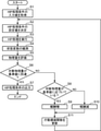
- It is a flowchart which shows an example of the process in the machine learning system shown in FIG.
- FIG. It is an overall block diagram of the machine learning system which concerns on the modification of this invention.
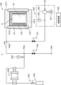
- FIG. 1 is an overall configuration diagram of a hot isotropic pressure pressurizing system (hereinafter, HIP system 1) to be learned in the embodiment of the present invention.
- the HIP system 1 includes a hot isotropic pressure pressurizing device (hereinafter, HIP device 100), a compressor 200, a vacuum pump 300, a gas collecting device 400, a valve 500, a pressure sensor 600, a valve 700, a valve 701, and a control device. Includes 800.
- the HIP apparatus 100 performs hot isotropic pressure pressurization treatment (hereinafter referred to as HIP treatment) on the object to be treated (W) using a pressure medium gas.
- HIP treatment hot isotropic pressure pressurization treatment
- FIG. 1 a cross-sectional view of the HIP device 100 is shown along the vertical direction.
- the HIP device 100 includes a pressure vessel 101, a heat insulating layer 102, and a heater 103.
- the valves 700 and 701 are examples of a pressure operating system that controls the pressure
- the pressure vessel 101 has, for example, a cylindrical shape.
- the pressure vessel 101 includes an upper lid 1011, a vessel body 1012, and a lower lid 1013.
- the upper lid 1011 closes the upper opening of the container body 1012.
- the lower lid 1013 closes the lower opening of the container body 1012.
- an internal space (cavity) of the main body airtightly isolated from the outside is formed inside the pressure vessel 101.
- a pipe 104 is connected to the pressure vessel 101, and a high-temperature and high-pressure pressure medium gas is supplied into the pressure vessel 101 through the pipe 104.
- the pressure medium gas is composed of, for example, argon gas, nitrogen gas, or the like whose pressure has been increased to about 10 to 300 MPa so that HIP treatment can be performed.
- the pipe 104 has a branch point 104a and branches from the branch point 104a in three directions: the HIP device 100 side, the compressor 200 side, and the gas discharge port 104c side. Further, the pipe 104 has a branch point 104b, and branches from the branch point 104b in three directions of the HIP device 100 side, the branch point 104a side, and the vacuum pump 300 side.
- the gas discharge port 104c is a discharge port for discharging the gas in the pressure vessel 101.
- the heat insulating layer 102 has an inverted cup-shaped structure that opens downward.
- the heat insulating layer 102 has a gas impermeable property.
- the heat insulating layer 102 may be filled with, for example, a graphite material woven with carbon fiber, a porous material such as ceramic fiber, or a fibrous material.
- the heater 103 is arranged in the hot zone P and generates heat to heat the pressure medium gas in the hot zone P.
- the heater 103 is controlled by the control device 800.
- the object W to be processed is placed on a mounting portion (not shown) provided inside the pressure vessel 101.
- the compressor 200 is connected to the HIP device 100 through a pipe 104.
- the compressor 200 pressurizes the gas that is the raw material of the pressure medium gas supplied from the gas collecting device 400 and supplies it to the HIP device 100 through the pipe 104.
- the vacuum pump 300 is connected to the HIP device 100 via a pipe 104 to evacuate the inside of the pressure vessel 101.
- the vacuum pump 300 includes a motor 301, a pump 302, and a vacuum sensor 303.
- the motor 301 powers the pump 302.
- the pump 302 evacuates the inside of the pressure vessel 101 by exhausting the air in the pressure vessel 101.
- the vacuum sensor 303 measures the degree of evacuation inside the pressure vessel 101.
- the gas collecting device 400 is connected to the compressor 200 via the pipe 104 and stores the gas that is the raw material of the pressure medium gas.
- the gas collecting device 400 supplies gas to the compressor 200 through the pipe 104.
- the valve 500 is provided on the pipe 104 between the compressor 200 and the gas collecting device 400.
- the valve 500 opens and closes the valve body under the control of the control device 800, and regulates the flow rate of gas from the gas collecting device 400 to the compressor 200.
- the pressure sensor 600 is provided on the pipe 104 between the branch point 104a and the compressor 200, and detects the pressure of the gas supplied from the compressor 200.
- the detected gas pressure may be adopted as the gas pressure in the pressure vessel 101.
- the valve 700 is provided on the pipe 104 between the branch point 104a and the vacuum pump 300.
- the valve 700 opens and closes the valve body under the control of the control device 800, and regulates the flow rate of gas between the HIP device 100 and the vacuum pump 300.
- the valve 701 is provided on the pipe 104 between the branch point 104b and the vacuum pump 300. Under the control of the control device 800, the valve 701 opens and closes the valve body according to the start and stop of the vacuum pump.
- the control device 800 is composed of a computer and controls the entire HIP system 1.
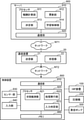
- FIG. 2 is an overall configuration diagram of a machine learning system for machine learning the HIP device 100 according to the embodiment.
- the machine learning system includes a server 900 and a communication device 20 in addition to the control device 800 described with reference to FIG.
- the server 900 and the communication device 20 are connected to each other so as to be able to communicate with each other via the network NT1.
- the communication device 20 and the control device 800 are connected to each other so as to be able to communicate with each other via the network NT2.
- Network NT1 is a wide area communication network such as the Internet.
- the network NT2 is, for example, a local area network.
- the server 900 is, for example, a cloud server composed of one or more computers.
- the communication device 20 is, for example, a computer owned by a user who uses the control device 800.
- the communication device 20 functions as a gateway that connects the control device 800 to the network NT1.
- the communication device 20 is realized by installing dedicated application software on a computer owned by the user himself / herself.
- the communication device 20 may be a dedicated device provided to the user by the manufacturer of the HIP device 100.
- the control device 800 is a control device that controls the HIP system 1 described with reference to FIG.
- the server 900 includes a processor 910 and a communication unit 920.
- the processor 910 is a control device including a CPU and the like.
- the processor 910 includes a reward calculation unit 911, an update unit 912, a determination unit 913, and a learning control unit 914.
- Each block included in the processor 910 may be realized by the processor 910 executing a machine learning program that causes the computer to function as a server 900 in the machine learning system, or may be realized by a dedicated electric circuit.
- the reward calculation unit 911 calculates the reward for the determination result of at least one HIP processing condition based on the state variable observed by the state observation unit 821.
- the update unit 912 updates the function for determining the HIP processing condition from the state variable observed by the state observation unit 821 based on the reward calculated by the reward calculation unit 911.
- the function the action value function described later is adopted.
- the determination unit 913 determines the HIP processing condition that gives the most reward by repeating the update of the function while changing at least one HIP processing condition.
- the learning control unit 914 controls the overall control of machine learning.
- the machine learning system of this embodiment learns HIP processing conditions by reinforcement learning. Reinforcement learning is better behavior for agents by having agents (behaviors) select certain behaviors based on environmental conditions, change the environment based on the selected behaviors, and reward agents for environmental changes. It is a machine learning method to learn the selection of. Q-learning and TD learning can be adopted as reinforcement learning. In the following description, Q-learning will be described as an example.
- the reward calculation unit 911, the update unit 912, the determination unit 913, the learning control unit 914, and the state observation unit 821 described later correspond to the agent.
- the communication unit 920 is an example of a state acquisition unit that acquires a state variable.
- the communication unit 920 is composed of a communication circuit that connects the server 900 to the network NT1.
- the communication unit 920 receives the state variable observed by the state observation unit 821 via the communication device 20.
- the communication unit 920 transmits the HIP processing conditions determined by the determination unit 913 to the control device 800 via the communication device 20.
- the communication device 20 includes a transmitter 21 and a receiver 22.
- the transmitter 21 transmits the state variable transmitted from the control device 800 to the server 900, and also transmits the HIP processing condition transmitted from the server 900 to the control device 800.
- the receiver 22 receives the state variable transmitted from the control device 800 and also receives the HIP processing condition transmitted from the server 900.
- the control device 800 includes a communication unit 810, a processor 820, a sensor unit 830, an input unit 840, and a memory 850.
- the communication unit 810 is a communication circuit for connecting the control device 800 to the network NT2.
- the communication unit 810 transmits the state variable observed by the state observation unit 821 to the server 900.
- the communication unit 810 receives the HIP processing conditions determined by the determination unit 913 of the server 900.
- the communication unit 810 receives a HIP process execution command, which will be described later, determined by the learning control unit 914.
- the processor 820 is a computer including a CPU and the like.
- the processor 820 includes a state observation unit 821, a processing execution unit 822, and an input determination unit 823.
- the communication unit 810 transmits the state variable acquired by the state observation unit 821 to the server 900.
- Each block included in the processor 820 is realized, for example, by executing a machine learning program in which the CPU functions as a control device 800 of the machine learning system.
- the state observation unit 821 acquires the physical quantity detected by the sensor unit 830 after the HIP process is executed. After executing the HIP processing, the state observing unit 821 observes a state variable including at least one physical quantity related to the object to be processed and at least one HIP processing condition. Specifically, the state observation unit 821 acquires HIP processing conditions based on the measured values of the sensor unit 830. Further, the state observation unit 821 acquires a physical quantity based on the measured value of the sensor unit 830 and the like. In the present embodiment, at least one physical quantity related to the object to be treated is a physical quantity related to densification or sintering of the object to be treated.
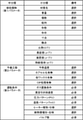
- FIG. 3 is a diagram showing an example of HIP processing conditions.
- HIP processing conditions are broadly classified into the middle category.
- the middle classification includes at least one of a first parameter relating to the object to be processed, a second parameter relating to the preliminary process of the HIP processing, and a third parameter relating to the operating conditions of the HIP apparatus 100.
- the parameter described as selection is a parameter whose value is specified by the user operating the input unit 840, and is not a parameter learned by machine learning. Therefore, in the present embodiment, parameters other than those described as selection are the learning targets. However, this is an example, and any one or more of the parameters described as selection may be targeted for learning.
- the first parameters are material name, weight, number, arrangement, form, shape, size, melting point, specific heat (C (T)), true density ( ⁇ (T)), bulk density ( ⁇ '(T)), and It contains at least one of the thermal expansion rates ( ⁇ (T)).
- the material name indicates the specific content such as the component and / or composition of the object to be treated.
- the weight indicates the total weight of the object to be treated. When the HIP device 100 processes a plurality of objects to be processed, the weight indicates the total weight per object to be processed.
- the number indicates the number of processed objects to be HIP-processed at one time.
- the number is added to the HIP processing conditions, for example, when a large amount of small objects to be processed are mounted in the pressure vessel 101 and when one large object to be processed is mounted in the pressure vessel 101, HIP processing is performed. This is because the result of is subject to change.
- the arrangement shows how to arrange the objects to be processed in each stage in the pressure vessel 101.
- information that the object to be processed is arranged in n rows ⁇ m columns in each stage, information that the object to be processed is arranged only in the center in the height direction in the pressure vessel 101, Alternatively, information that one object to be processed is arranged at the bottom of the pressure vessel 101 can be adopted.
- the form indicates the presence or absence of encapsulation treatment (encapsulation) for the object to be treated.
- Encapsulation is a pretreatment performed on the object to be treated in the preliminary step.
- the shape indicates the outer shape of the object to be treated.
- information such as a sphere, an oblong ellipsoid, an oblate ellipsoid, a rectangular parallelepiped, a cube, and a cylinder can be adopted.
- the shape can be observed using, for example, a camera or a three-dimensional measuring instrument.
- the object to be processed when the object to be processed is a rectangular parallelepiped, information such as width, height, and depth is adopted, and when the object to be processed is cylindrical, information such as average diameter and height is adopted.
- the dimensions can be measured using, for example, a camera or a three-dimensional measuring device.
- the melting point indicates the temperature at which the object to be treated melts.
- the specific heat is the specific heat of the object to be treated, and varies depending on the material of the object to be treated.
- the true density is a density in which only the volume occupied by the object to be treated is used as the volume for density calculation.
- the bulk density is the density when a container having a constant volume is fully filled with the object to be treated and the internal volume thereof is taken as the volume.
- the coefficient of thermal expansion is the coefficient of thermal expansion of the object to be treated.
- the shape, dimensions, melting point, specific heat, true density, bulk density, and thermal expansion rate are each input by the user via the input unit 840. Therefore, the state observation unit 821 may acquire these parameters from the input unit 840.
- the second parameter includes preheating temperature, encapsulation presence / absence, dewaxing presence / absence, and CIP treatment presence / absence.
- the preheating temperature indicates the temperature in the preheat treatment performed on the object to be treated before the HIP treatment.
- the presence or absence of encapsulation indicates whether or not the object to be treated before the HIP treatment has been encapsulated.
- the presence or absence of dewaxing indicates whether or not the treatment for removing the wax has been performed on the object to be treated before the HIP treatment.
- the presence or absence of CIP processing indicates whether or not CIP processing is performed on the object to be processed before HIP processing.
- CIP Cold Isotropic Pressing
- Each of these second parameters is input by the user via the input unit 840. Therefore, the state observation unit 821 may acquire these parameters from the input unit 840.
- the third parameter includes gas replacement conditions, evacuation reach, pressure pattern, temperature pattern, heater type, heater specifications, heat insulating layer type, and heat insulating layer specifications, and valves.
- the gas replacement condition is a condition relating to a gas replacement operation in which the pressure vessel 101 is filled with gas and then discarded. The higher the filling pressure in the gas replacement operation and the larger the number of gas replacements, the less impurities contained in the gas.
- the degree of evacuation is the degree of evacuation in the pressure vessel 101. The degree of evacuation is measured by the vacuum sensor 303.
- the pressure pattern shows the change pattern of the pressure in the pressure vessel 101 during the HIP treatment.
- the temperature pattern shows the change pattern of the temperature in the pressure vessel 101 during the HIP treatment.
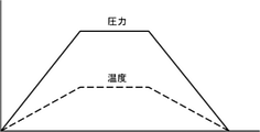
- FIG. 4 is a graph showing an example of a pressure pattern and a temperature pattern.
- the vertical axis shows pressure and temperature
- the horizontal axis shows time.
- Both the pressure pattern and the temperature pattern are trapezoidal.
- the pressure pattern and the temperature pattern increase with a constant slope until the maximum pressure and the maximum temperature are reached, respectively, maintain the maximum pressure and the maximum temperature for a certain period of time, and then decrease with a constant slope.
- the pressure pattern is machine-learned by changing the slope at the time of increase, the slope at the time of decrease, the maintenance period of the maximum pressure, and the like.
- the temperature pattern is machine-learned by changing the slope at the time of increase, the slope at the time of decrease, the maintenance period of the maximum temperature, and the like.
- the pressure pattern the data input by the user via the input unit 840 may be adopted, or the measured value of the pressure sensor 600 may be adopted.
- the heater type and heater specifications are information indicating the material of the heater 103 and / or the number of heaters 103.
- the heat insulating layer type and the heat insulating layer specification are the materials of the heat insulating layer 102.
- information indicating the presence / absence of the rapid cooling function and / or the maximum usable temperature may be adopted.
- the valves have an opening degree of valves 700, 701, etc., which are pressure operation systems.
- FIG. 5 is a diagram showing an example of a physical quantity.
- the physical quantity includes a physical quantity related to densification and a physical quantity related to sintering.
- the same parameters are adopted for the physical quantity related to densification and the physical quantity related to sintering, but different parameters may be adopted.
- different reference values are adopted for the physical quantity related to densification and the physical quantity related to sintering. Therefore, machine learning is performed independently for densification and sintering. Therefore, different machine learning results can be obtained for each of densification and sintering.
- the middle classification includes material properties, mechanical properties, and shape properties.
- the material property indicates the property of the object to be treated itself.
- the mechanical property indicates the mechanical property of the object to be processed.
- the shape characteristic shows the characteristic regarding the shape of the object to be processed.
- Material properties include at least one of internal defects, density, grain size, electrical resistance / insulation, permittivity, transparency, ionic conductivity, and electrical conductivity.
- Internal defects are defects such as residual pores of the object to be treated. Internal defects are measured using a measuring method such as an ultrasonic flaw detection method (UT method).
- UT method ultrasonic flaw detection method
- Density is the density of the object to be treated. Density is measured, for example, by the Archimedes method. For the density, for example, the ratio of the true density to the apparent density may be adopted.
- the crystal grain size is the rate of change of the crystal grain size before and after the HIP treatment with respect to the object to be treated.
- the crystal grain size is measured, for example, by observing the cross section of the object to be treated with a scanning electron microscope (SEM).
- SEM scanning electron microscope
- the crystal grain size may be measured by SUMP (Suzuki's Universal Micro Printing Method).
- Electrical resistance / insulation indicates the difficulty of passing electricity of the object to be treated after HIP treatment. Electrical resistance / insulation can be obtained, for example, by measuring the resistance value of the object to be treated.
- the permittivity is obtained, for example, by a permittivity meter.
- Transparency is measured, for example, by a spectrophotometer or a transmission test.
- the ionic conductivity is, for example, the AC impedance of the object to be processed.
- AC impedance is measured using, for example, an FFT analyzer, FRA method, or impedance method.
- the electric conductivity is measured by, for example, an AC two-electrode method or an electromagnetic induction method.
- Mechanical properties include at least one of tensile strength, fatigue life, toughness, creep strength, wear rate, and hardness.
- Tensile strength is measured by a tensile test.
- Fatigue life is measured by a fatigue test.
- Toughness is estimated from tensile tests.
- Creep strength is measured by a creep test.
- the wear rate is measured by a wear test.
- Hardness is measured by a hardness tester.
- Shape characteristics include shape changes.
- the shape change is the rate of change in the shape of the object to be treated before and after the HIP treatment.
- the shape change is performed, for example, by image processing of an image taken by a three-dimensional dimension measuring instrument or a camera.
- image processing it is required that the shapes of the objects to be processed are similar before and after the HIP processing. Therefore, the degree of similarity of the shape change is measured.
- the density may be adopted as a physical quantity when the object to be treated is glass.
- Tensile strength, fatigue life, electrical resistance / insulation, toughness, creep strength, wear rate, and hardness are preferably adopted as physical quantities when the object to be treated is metal or ceramics.
- the crystal grain size is preferably adopted as a physical quantity when the object to be treated is a metal. It is preferable that the dielectric constant, the ionic conductivity, and the electric conductivity are adopted as physical quantities when the object to be treated is ceramics.
- the transparency is preferably adopted as a physical quantity when the object to be treated is ceramics or glass.
- the process execution unit 822 controls the execution of the HIP process by the HIP device 100.
- the input determination unit 823 automatically or manually determines whether or not the process is mass production. When the input determination unit 823 automatically determines whether or not it is a mass production process, if the number of times the condition number input to the input unit 840 exceeds the reference number, the HIP device 100 determines that the HIP device 100 is in the mass production process. do.
- the condition number is an identification number for specifying one HIP processing condition.
- the HIP processing condition specified by the condition number includes at least the HIP processing condition described as selection among the HIP processing conditions shown in FIG.
- the input determination unit 823 manually determines whether or not it is a mass production process, if data indicating that it is a mass production process is input to the input unit 840, the HIP device 100 determines that it is in the mass production process. When in the mass production process, the control device 800 does not perform machine learning.
- the memory 850 is, for example, a non-volatile storage device, and stores the finally determined optimum HIP processing conditions and the like.
- the sensor unit 830 is various sensors used for measuring the HIP processing conditions exemplified in FIG. 3 and the physical quantity exemplified in FIG. Specifically, the sensor unit 830 is a temperature sensor for measuring the temperature inside the pressure vessel 101, a pressure sensor 600, a vacuum sensor 303, and the like.
- the vacuum sensor 303 included in the vacuum pump 300 is illustrated as being included in the sensor unit 830 of the control device 800.
- the input unit 840 is an input device such as a keyboard and a mouse.
- the sensor unit 830 is provided inside the control device 800, but this is an example and may be provided outside the control device 800, and the installation location of the sensor unit 830 is not particularly limited. ..
- FIG. 6 is a flowchart showing an example of processing in the machine learning system shown in FIG.
- the learning control unit 914 acquires the input value of the HIP processing condition input by the user using the input unit 840.
- the input value acquired here is an input value for the HIP processing condition described as selection among the HIP processing conditions listed in FIG.
- the learning control unit 914 determines at least one HIP processing condition and a set value for the HIP processing condition.
- the HIP processing condition to be set is at least one HIP processing condition other than the HIP processing condition described as selection among the HIP processing conditions listed in FIG. 3, and the set value can be set. HIP processing conditions.
- the set value of the HIP processing condition determined corresponds to the action in reinforcement learning.
- the learning control unit 914 randomly selects a set value for each of the HIP processing conditions to be set.
- the set value is randomly selected from within a predetermined range for each of the HIP processing conditions.
- the ⁇ -greedy method can be adopted as a method for selecting the set value of the HIP processing condition.
- step S3 the learning control unit 914 causes the HIP device 100 to start the HIP process through the control device 800 by transmitting the HIP process execution command to the control device 800.
- the processing execution unit 822 sets the HIP processing conditions according to the HIP processing execution command and starts the HIP processing.
- the HIP processing execution command includes an input value of the HIP processing condition set in step S1 and a set value of the HIP processing condition determined in step S2.
- the state observation unit 821 observes the state variable (step S4).
- the state observing unit 821 has the physical quantity related to densification or sintering shown in FIG. 4, and the HIP processing conditions in which the state is observed by the sensor unit 830 or the like among the HIP processing conditions shown in FIG. And as a state variable.
- the physical quantity may be input to the control device 800 by, for example, the user operating the input unit 840, or may be input to the control device 800 by communication between the measuring instrument for measuring the physical quantity and the control device 800.
- the state observation unit 821 transmits the acquired state variable to the server 900 via the communication unit 810.
- step S5 the determination unit 913 evaluates the physical quantity.
- the determination unit 913 determines whether or not the physical quantity to be evaluated (hereinafter referred to as a target physical quantity) among the physical quantities acquired in step S4 has reached a predetermined reference value, thereby determining the physical quantity. evaluate.
- the target physical quantity is one or more physical quantities among the physical quantities listed in FIG.
- the reference value has a plurality of reference values corresponding to each target physical quantity.
- the reference value for example, a predetermined value indicating that the target physical quantity has reached a certain reference can be adopted.
- the reference value when machine learning is performed for densification, the reference value is a predetermined value for densification, and when machine learning is performed for sintering, the reference value is a predetermined value for sintering.
- the reference value may be, for example, a value including an upper limit value and a lower limit value. In this case, when the target physical quantity falls within the range between the upper limit value and the lower limit value, it is determined that the reference value has been reached.
- the reference value may be one value. In this case, it is determined that a certain standard is satisfied when the target physical quantity exceeds the reference value or falls below the reference value.
- the determination unit 913 determines that the target physical quantity has reached the reference value (YES in step S6)
- the determination unit 913 outputs the HIP processing condition set in step S2 as the final HIP processing condition (step S7).
- the determination unit 913 determines that the physical quantity has not reached the reference value (NO in step S6)
- the process proceeds to step S8.
- the determination unit 913 may determine YES in step S6 when all the target physical quantities reach the reference values.
- step S8 the reward calculation unit 911 determines whether or not the target physical quantity is approaching the reference value.
- the reward calculation unit 911 increases the reward to the agent (step S9).
- the reward calculation unit 911 reduces the reward to the agent (step S10).
- the reward calculation unit 911 may increase or decrease the reward according to a predetermined increase / decrease value of the reward.
- the reward calculation unit 911 may perform the determination in step S8 for each of the plurality of target physical quantities.
- the reward calculation unit 911 may increase or decrease the reward for each of the plurality of target physical quantities based on the determination result in step S8. Further, the increase / decrease value of the reward may be different depending on the target physical quantity.
- step S10 when the target physical quantity does not approach the reference value (NO in step S8), the process of reducing the reward may be omitted (step S10). In this case, the reward will be given only when the target physical quantity is close to the reference value.
- the update unit 912 updates the action value function using the reward given to the agent.
- the Q-learning adopted in this embodiment is a method of learning a Q-value (Q (s, a)) which is a value for selecting an action a under a certain environmental state s.
- the environmental state st corresponds to the state variable of the above flow.
- the action a having the highest Q (s, a) is selected in a certain environmental state s.
- various actions a are taken under a certain environmental state s by trial and error, and the correct Q (s, a) is learned using the reward at that time.
- the update formula of the action value function Q ( st , at) is shown by the following formula (1).
- st and at represent the environmental state and the behavior at time t , respectively.
- the action at changes the environmental state to st + 1 and the change in the environmental state calculates the reward rt + 1 .
- the term with max is the Q value (Q ( st + 1 , a)) when the most valuable action a known at that time is selected under the environmental state st + 1, and is multiplied by ⁇ .
- ⁇ is a discount rate, and takes a value of 0 ⁇ ⁇ 1 (usually 0.9 to 0.99).
- ⁇ is a learning coefficient and takes a value of 0 ⁇ ⁇ 1 (usually about 0.1).
- This update formula is based on the Q value when the best action in the next environmental state s t + 1 by the action a is taken, rather than the Q value Q (st, at ) of the action a in the state s. If maxQ (st + 1 , a) is larger, then Q (st, at ) is increased. On the other hand, this update formula makes Q ( st, at ) smaller if ⁇ ⁇ maxQ (st + 1 , a) is smaller than Q (st, at ) . That is, the value of a certain action a in one state st is brought closer to the value of the best action in the next state st + 1 . Thereby, the optimum HIP processing conditions are determined.
- step S11 When the process of step S11 is completed, the process returns to step S2, the set value of the HIP processing condition is changed, and the action value function is updated in the same manner.
- the update unit 912 has updated the action value function, but the present invention is not limited to this, and the action value table may be updated.
- the values for all the states and actions pairs (s, a) may be stored in a table format.
- Q (s, a) may be represented by an approximate function that approximates the values for all state-behavior pairs (s, a).
- This approximation function may be constructed by a multi-layered neural network. In this case, the neural network may perform online learning in which the data obtained by actually operating the HIP device 100 is learned in real time and reflected in the next action.
- HIP processing conditions have been developed by changing the HIP processing conditions so that high-quality HIP-processed products can be obtained.
- it is required to find a relationship between the evaluation of the object to be processed and the HIP processing conditions.
- FIG. 3 since the types of HIP processing conditions are enormous, an extremely large number of physical models are required to define such relationships, and such relationships are described by the physical models. It was found that it is difficult to do.
- it is also required to artificially find out which parameter influences the evaluation of which object to be processed, and this construction is difficult.
- At least one of the above-mentioned first to third parameters and at least one physical quantity of material properties, mechanical properties, and shape properties are observed as state variables. .. Then, the reward for the determination result of the HIP processing condition is calculated based on the observed state variable, and the action value function for determining the HIP processing condition from the state variable is updated based on the calculated reward.
- the HIP processing conditions that obtain the most rewards are learned by repeating the update.
- the HIP processing conditions are determined by machine learning without using the above-mentioned physical model. As a result, the present embodiment can easily determine appropriate HIP processing conditions without relying on many years of experience by a skilled technician.
- FIG. 7 is an overall configuration diagram of a machine learning system according to a modified example of the present invention.
- the machine learning system according to this modification is composed of the control device 800A alone.
- the control device 800A includes a processor 820A, an input unit 880, and a sensor unit 890.
- the processor 820A includes a machine learning unit 860 and a HIP processing unit 870.
- the machine learning unit 860 includes a reward calculation unit 861, an update unit 862, a determination unit 863, and a learning control unit 864.
- the reward calculation unit 861 to the learning control unit 864 are the same as the reward calculation unit 911 to the learning control unit 914 shown in FIG. 2, respectively.
- the HIP processing unit 870 includes a state observation unit 871, a processing execution unit 872, and an input determination unit 873.
- the state observation unit 871 to the input determination unit 873 are the same as the state observation unit 821, the processing execution unit 822, and the input determination unit 823 shown in FIG. 2, respectively.
- the input unit 880 and the sensor unit 890 are the same as the input unit 840 and the sensor unit 830 shown in FIG. 2, respectively.
- the state observation unit 871 is an example of a state acquisition unit that acquires state information.
- the sensor unit 890 may be provided inside the control device 800A or outside the control device 800A, and the installation location of the sensor unit 890 is not particularly limited.
- the optimum HIP processing conditions can be learned by the control device 800A alone.
- the state variables were observed after the HIP processing was completed, but this is an example, and a plurality of state variables may be observed during one HIP processing.
- a state variable is composed of only parameters that can be measured instantaneously, a plurality of state variables can be observed during one HIP process. As a result, the learning time can be shortened.
- the communication method according to the present invention is executed by various processes when the control device 800 shown in FIG. 2 communicates with the server 900. Further, the learning program according to the present invention is realized by a program that causes a computer to function as the server 900 shown in FIG.
- the machine learning method is a hot isotropic pressure pressurizing treatment condition of a hot isotropic pressure pressurizing system in which a hot isotropic pressure pressurizing treatment is performed on an object to be treated by using a pressure medium gas.
- the hot isotropic pressure pressurizing system includes a hot isotropic pressure pressurizing device having a pressure vessel for storing the object to be processed, a heat insulating layer, and a heater.
- a vacuum device for evacuating the inside of the pressure vessel, a compressor for supplying the pressure medium gas to the pressure vessel, a pressure operation system for controlling the pressure in the pressure vessel, and the heat.
- a control device for controlling an isotropic pressure pressurization system is provided, and a state variable including at least one physical quantity related to the object to be processed and at least one hot isotropic pressure pressurization treatment condition is acquired, and the state variable is obtained. Based on the state variable, the reward for the determination result of the at least one hot isotropic pressure processing condition is calculated, and while changing the at least one hot isotropic pressure processing condition, the state variable is used.
- the function for determining at least one hot isotropic pressure processing condition is updated based on the reward, and by repeating the update of the function, the hot isotropic pressure at which the reward is most obtained is obtained.
- the pressurization treatment conditions are determined, and the at least one hot isotropic pressurization treatment condition includes a first parameter relating to the object to be treated and a second parameter relating to the preliminary step of the hot isotropic pressure pressurizing treatment.
- the third parameter relating to at least one operating condition of the hot isotropic pressurizing device, the vacuum device, the compressor, and the pressure operating system, and the at least one physical quantity. Is at least one of the material properties, shape properties, and mechanical properties of the object to be treated.
- the first parameter regarding the object to be processed the second parameter regarding the preliminary step of the hot isotropic pressure pressurization process, the hot isotropic pressure pressurizing device, the vacuum device, the compressor, and the pressure operation.
- At least one of the third parameters for at least one operating condition of the system is acquired as a state variable.
- at least one of the material property, shape property, and mechanical property of the object to be processed is acquired as a state variable.
- the reward for the determination result of the hot isobaric pressurization treatment condition is calculated based on the acquired state variable, and the hot isotropic pressurization treatment condition is determined from the state variable based on the calculated reward.
- the function for this is updated, and this update is repeated to learn the hot isotropic pressure processing condition in which the most reward is obtained. Therefore, this configuration can easily determine the hot isotropic pressure processing conditions without relying on many years of experience by a skilled technician.
- the first parameter is at least one of the material name, weight, number, arrangement, form, shape, size, melting point, specific heat, true density, bulk density, and thermal expansion rate of the object to be treated. May be.
- At least one of the material name, weight, number, arrangement, form, shape, dimension, melting point, specific heat, true density, bulk density, and thermal expansion rate of the object to be processed is a state variable related to the object to be processed. Since it has been acquired and machine learning has been performed, it is possible to determine appropriate hot isotropic pressure processing conditions in consideration of the state of the object to be processed.
- the second parameter may be at least one of preheating temperature, presence / absence of encapsulation, presence / absence of dewaxing, and cold isotropic pressure pressure treatment.
- At least one of the preheating temperature, the presence / absence of encapsulation, the presence / absence of dewaxing, and the cold isotropic pressure pressure treatment are acquired as state variables related to the preliminary process, and machine learning is performed.
- Appropriate hot isotropic pressure processing conditions can be determined in consideration of the state of the preliminary process.
- the third parameter is the replacement condition of the gas used for the hot isotropic pressure pressurization, the degree of evacuation by the vacuum device, the pressure pattern of the compressor, and the temperature of the heater. It may be at least one of a pattern, a type of the heater, a specification of the heater, a type of the heat insulating layer, and a specification of the heat insulating layer.
- the type of heat insulating layer, and at least one of the specifications of the heat insulating layer are acquired as state variables related to the operating conditions, and machine learning is performed. I can decide.
- the at least one physical quantity may be a physical quantity parameter related to densification or sintering.
- the optimum hot isotropic pressure treatment condition or subject for densification of the object to be processed is performed.
- the optimum hot isotropic pressure processing conditions for sintering the processed material can be easily determined.
- the function may be updated in real time using deep reinforcement learning.
- the function since the function is updated in real time using deep reinforcement learning, the function can be updated accurately and promptly.
- the reward in the calculation of the reward, may be increased when the at least one physical quantity approaches a predetermined reference value corresponding to each physical quantity.
- the reward is increased as the physical quantity approaches the reference value, so that the physical quantity can quickly reach the reference value.
- each process provided in the above machine learning method may be implemented in the machine learning device provided, or may be implemented and distributed as a machine learning program.
- This machine learning device may be configured by a server or a hot isotropic pressure pressurizing device.
- the hot isotropic pressure pressurizing treatment of the hot isotropic pressure pressurizing system that performs the hot isotropic pressure pressurizing treatment using the pressure medium gas on the object to be treated. It is a communication method of the control device of the hot isotropic pressure pressurizing system when machine learning the conditions, and the hot isotropic pressure pressurizing system is a pressure vessel for storing the object to be processed, a heat insulating layer, and the like.
- a hot isotropic pressure pressurizing device having a heater, a vacuum device for evacuating the inside of the pressure vessel, a compressor for supplying the pressure medium gas to the pressure vessel, and the inside of the pressure vessel.
- a pressure operating system for controlling the pressure and the control device are provided, and a state variable including at least one physical quantity related to the object to be processed and at least one hot isotropic pressure processing condition is observed.
- the state variable is transmitted over the network to receive at least one machine-learned hot isotropic pressurization condition, and the at least one hot isotropic pressurization condition relates to the object to be treated.
- Such a communication method can also be implemented in a hot isotropic pressure pressurizing device.
Landscapes
- Engineering & Computer Science (AREA)
- Physics & Mathematics (AREA)
- General Physics & Mathematics (AREA)
- Theoretical Computer Science (AREA)
- General Engineering & Computer Science (AREA)
- Software Systems (AREA)
- Medical Informatics (AREA)
- Evolutionary Computation (AREA)
- Data Mining & Analysis (AREA)
- Computer Vision & Pattern Recognition (AREA)
- Computing Systems (AREA)
- Artificial Intelligence (AREA)
- Mathematical Physics (AREA)
- Automation & Control Theory (AREA)
- Mechanical Engineering (AREA)
- Testing And Monitoring For Control Systems (AREA)
- Powder Metallurgy (AREA)
Abstract
取得した状態変数に基づいて、熱間等方圧加圧処理条件の決定結果に対する報酬を計算し、状態変数から少なくとも1つの熱間等方圧加圧処理条件を決定するための関数を、報酬に基づいて更新し、関数の更新を繰り返すことによって、報酬が最も多く得られる熱間等方圧加圧処理条件を決定し、熱間等方圧加圧処理条件は、被処理物に関する第1パラメータと、熱間等方圧加圧処理の予備工程に関する第2パラメータと、熱間等方圧加圧装置、真空装置、圧縮機、及び圧力操作系統の少なくとも1つの運転条件に関する第3パラメータと、のうちの少なくとも1つであり、少なくとも1つの物理量は、被処理物の材料特性、形状特性、及び機械的特性のうちの少なくとも1つである。
Description
本発明は、熱間等方圧加圧装置の熱間等方圧加圧条件を機械学習する技術に関するものである。
従来、HIP法(Hot Isostatic Pressing法:熱間等方圧加圧装置を用いたプレス方法)では、数10~数100MPaの高圧に設定された雰囲気の圧媒ガスのもと、焼結製品(セラミックス等)や鋳造製品等の被処理物が、その再結晶温度以上の高温に加熱され処理される(例えば、特許文献1)。当該方法では、被処理物中の残留気孔を消滅させることができるという特徴がある。高品質なHIP処理品を得るためには、加圧条件及び加熱条件等のHIP処理条件を適切に決定することが要求される。
しかしながら、従来、HIP処理条件は、熟練した技術者による長年の経験を頼りに決定されていた。そのため、被処理物に対する適切なHIP処理条件を容易に決定することが困難であった。
本発明は、このような課題を解決するためになされたものであり、被処理物に対する適切なHIP処理条件を熟練した技術者による長年の経験を頼らずに容易に決定できる機械学習方法などを提供することである。
本発明の一態様に係る機械学習方法は、被処理物に圧媒ガスを用いて熱間等方圧加圧処理を行う熱間等方圧加圧システムの熱間等方圧加圧処理条件を機械学習装置が決定する機械学習方法であって、前記熱間等方圧加圧システムは前記被処理物を格納する圧力容器、断熱層、及びヒーターを有する熱間等方圧加圧装置と、前記圧力容器内を真空にするための真空装置と、前記圧力容器に前記圧媒ガスを供給するための圧縮機と、前記圧力容器内の圧力を制御するための圧力操作系統と、前記熱間等方圧加圧システムを制御する制御装置と、を備え、前記被処理物に関する少なくとも1つの物理量と、少なくとも1つの熱間等方圧加圧処理条件とを含む状態変数を取得し、前記状態変数に基づいて、前記少なくとも1つの熱間等方圧加圧処理条件の決定結果に対する報酬を計算し、前記少なくとも1つの熱間等方圧加圧処理条件を変更させながら、前記状態変数から前記少なくとも1つの熱間等方圧加圧処理条件を決定するための関数を、前記報酬に基づいて更新し、前記関数の更新を繰り返すことによって、前記報酬が最も多く得られる熱間等方圧加圧処理条件を決定し、前記少なくとも1つの熱間等方圧加圧処理条件は、前記被処理物に関する第1パラメータと、前記熱間等方圧加圧処理の予備工程に関する第2パラメータと、前記熱間等方圧加圧装置、前記真空装置、前記圧縮機、及び前記圧力操作系統の少なくとも1つの運転条件に関する第3パラメータと、のうちの少なくとも1つであり、前記少なくとも1つの物理量は、前記被処理物の材料特性、形状特性、及び機械的特性のうちの少なくとも1つである。
本発明によれば被処理物に対する適切な熱間等方圧加圧処理条件を熟練した技術者による長年の経験を頼らずに容易に決定できる。
以下添付図面を参照しながら、本発明の実施の形態について説明する。なお、以下の実施の形態は、本発明を具体化した一例であって、本発明の技術的範囲を限定する性格のものではない。
図1は、本発明の実施の形態において学習対象となる熱間等方圧加圧システム(以下、HIPシステム1)の全体構成図である。HIPシステム1は、熱間等方圧加圧装置(以下、HIP装置100)、圧縮機200、真空ポンプ300、ガス集合装置400、バルブ500、圧力センサー600、バルブ700、バルブ701、及び制御装置800を含む。HIP装置100は、被処理物(W)に対して圧媒ガスを用いて熱間等方圧加圧処理(以下、HIP処理)を行う。図1において、HIP装置100は鉛直方向に沿った断面図が示されている。HIP装置100は、圧力容器101、断熱層102、及びヒーター103を含む。バルブ700、701は圧力容器101内の圧力を制御する圧力操作系統の一例である。
圧力容器101は、例えば円筒状の形状を有する。圧力容器101は、上蓋1011、容器胴1012、及び下蓋1013を含む。上蓋1011は、容器胴1012の上側の開口を塞ぐ。下蓋1013は、容器胴1012の下側の開口を塞ぐ。圧力容器101の内部には外部から気密的に隔離された本体内部空間(空洞)が形成されている。
圧力容器101には、配管104が連結されており、配管104を通じて高温高圧の圧媒ガスが圧力容器101内に供給される。圧媒ガスは、HIP処理が可能なように、10~300MPa程度に昇圧された例えばアルゴンガスや窒素ガス等で構成されている。
配管104は、分岐点104aを有し、分岐点104aからHIP装置100側、圧縮機200側、及びガス放出口104c側の3方向に分岐している。さらに配管104は、分岐点104bを有し、分岐点104bから、HIP装置100側、分岐点104a側、及び真空ポンプ300側の3方向に分岐している。ガス放出口104cは、圧力容器101内のガスを放出するための放出口である。
断熱層102は、下方に向かって開口した逆コップ状の構造を有している。断熱層102は、ガス不透過性の特性を有している。断熱層102には、例えばカーボンファイバを編み込んだ黒鉛質材料、セラミックファイバなどの多孔質材料、繊維質材料が充填されていてもよい。
ヒーター103は、ホットゾーンPに配置され、発熱することで、ホットゾーンP内の圧媒ガスを加熱する。ヒーター103は制御装置800によって制御される。被処理物Wは圧力容器101の内部に設けられた図略の載置部の上に載置される。
圧縮機200は、配管104を通じてHIP装置100と接続されている。圧縮機200は、ガス集合装置400から供給される圧媒ガスの原料となるガスを加圧して配管104を通じてHIP装置100に供給する。
真空ポンプ300は、配管104を介してHIP装置100と接続され、圧力容器101の内部を真空にする。真空ポンプ300は、モータ301、ポンプ302、及び真空センサー303を含む。モータ301はポンプ302に動力を与える。ポンプ302は、圧力容器101内の空気を排気することによって圧力容器101の内部を真空にする。真空センサー303は、圧力容器101の内部の真空引き到達度を計測する。
ガス集合装置400は、配管104を介して圧縮機200と接続され、圧媒ガスの原料となるガスを貯留する。ガス集合装置400は、配管104を通じてガスを圧縮機200に供給する。
バルブ500は、圧縮機200とガス集合装置400との間の配管104上に設けられている。バルブ500は、制御装置800の制御の下、弁体を開閉し、ガス集合装置400から圧縮機200へのガスの流量を調節する。
圧力センサー600は、分岐点104aと圧縮機200との間の配管104上に設けられ、圧縮機200から供給されるガスの圧力を検出する。検出されるガスの圧力は、圧力容器101内のガスの圧力として採用されてもよい。
バルブ700は、分岐点104aと真空ポンプ300との間の配管104上に設けられている。バルブ700は、制御装置800の制御の下、弁体を開閉し、HIP装置100と真空ポンプ300との間のガスの流量を調節する。バルブ701は、分岐点104bと真空ポンプ300との間の配管104上に設けられている。バルブ701は、制御装置800の制御の下、真空ポンプの運転・停止に合わせて弁体を開閉する。
制御装置800は、コンピュータで構成され、HIPシステム1の全体制御を司る。
図2は、実施の形態におけるHIP装置100を機械学習させる機械学習システムの全体構成図である。機械学習システムは、図1で説明した制御装置800に加えてサーバ900及び通信装置20を含む。サーバ900及び通信装置20はネットワークNT1を介して相互に通信可能に接続されている。通信装置20及び制御装置800はネットワークNT2を介して相互に通信可能に接続されている。ネットワークNT1は、例えばインターネットなどの広域通信網である。ネットワークNT2は、例えばローカルエリアネットワークである。サーバ900は、例えば1以上のコンピュータで構成されるクラウドサーバである。通信装置20は、例えば制御装置800を使用するユーザが所持するコンピュータである。通信装置20は、制御装置800をネットワークNT1に接続するゲートウェイとして機能する。通信装置20は、ユーザ自身が所持するコンピュータに専用のアプリケーションソフトウェアをインストールすることで実現される。或いは通信装置20は、HIP装置100の製造メーカがユーザに提供する専用の装置であってもよい。制御装置800は、図1で説明したHIPシステム1を制御する制御装置である。
以下、各装置の構成を具体的に説明する。サーバ900は、プロセッサ910及び通信部920を含む。プロセッサ910は、CPUなどを含む制御装置である。プロセッサ910は、報酬計算部911、更新部912、決定部913、及び学習制御部914を含む。プロセッサ910が備える各ブロックは、コンピュータを機械学習システムにおけるサーバ900として機能させる機械学習プログラムをプロセッサ910が実行することで実現されてもよいし、専用の電気回路で実現されてもよい。
報酬計算部911は、状態観測部821が観測した状態変数に基づいて、少なくとも1つのHIP処理条件の決定結果に対する報酬を計算する。
更新部912は、状態観測部821が観測した状態変数からHIP処理条件を決定するための関数を、報酬計算部911によって計算された報酬に基づいて更新する。関数としては、後述の行動価値関数が採用される。
決定部913は、少なくとも1つのHIP処理条件を変更させながら、関数の更新を繰り返すことによって、報酬が最も多く得られるHIP処理条件を決定する。
学習制御部914は、機械学習の全体制御を司る。本実施の形態の機械学習システムは強化学習によってHIP処理条件を学習する。強化学習とは、エージェント(行動主体)が環境の状況に基づいてある行動を選択し、選択した行動に基づいて環境を変化させ、環境変化に伴う報酬をエージェントに与えることにより、エージェントにより良い行動の選択を学習させる機械学習手法である。強化学習としては、Q学習及びTD学習が採用できる。以下の説明では、Q学習を例に挙げて説明する。本実施の形態では、報酬計算部911、更新部912、決定部913、学習制御部914、及び後述する状態観測部821がエージェントに相当する。本実施の形態において、通信部920は、状態変数を取得する状態取得部の一例である。
通信部920は、サーバ900をネットワークNT1に接続する通信回路で構成される。通信部920は、状態観測部821により観測された状態変数を通信装置20を介して受信する。通信部920は、決定部913が決定したHIP処理条件を通信装置20を介して制御装置800に送信する。
通信装置20は、送信器21及び受信器22を含む。送信器21は、制御装置800から送信された状態変数をサーバ900に送信すると共に、サーバ900から送信されたHIP処理条件を制御装置800に送信する。受信器22は、制御装置800から送信された状態変数を受信すると共に、サーバ900から送信されたHIP処理条件を受信する。
制御装置800は、通信部810、プロセッサ820、センサー部830、入力部840、及びメモリ850を含む。
通信部810は、制御装置800をネットワークNT2に接続するための通信回路である。通信部810は、状態観測部821によって観測された状態変数をサーバ900に送信する。通信部810は、サーバ900の決定部913が決定したHIP処理条件を受信する。通信部810は、学習制御部914が決定した後述するHIP処理実行コマンドを受信する。
プロセッサ820は、CPUなどを含むコンピュータである。プロセッサ820は、状態観測部821、処理実行部822、及び入力判定部823を含む。通信部810は、状態観測部821が取得した状態変数をサーバ900に送信する。プロセッサ820が備える各ブロックは、例えばCPUが機械学習システムの制御装置800として機能させる機械学習プログラムを実行することで実現される。
状態観測部821は、HIP処理実行後において、センサー部830が検出した物理量を取得する。状態観測部821は、HIP処理実行後において被処理物に関する少なくとも1つの物理量と、少なくとも1つのHIP処理条件とを含む状態変数を観測する。具体的には、状態観測部821は、センサー部830の計測値に基づいてHIP処理条件を取得する。また、状態観測部821は、センサー部830の計測値などに基づいて物理量を取得する。本実施の形態において、被処理物に関する少なくとも1つの物理量は、被処理物の緻密化又は焼結に関する物理量である。
図3は、HIP処理条件の一例を示す図である。HIP処理条件は、大きく中分類に分類される。中分類には、被処理物に関する第1パラメータと、HIP処理の予備工程に関する第2パラメータと、HIP装置100の運転条件に関する第3パラメータとのうち少なくとも1つが含まれる。表中、選択と記載されたパラメータはユーザが入力部840を操作することによって値を指定したパラメータであり、機械学習によって学習されるパラメータではない。したがって、本実施の形態では選択と記載された以外のパラメータが学習対象となる。但し、これは一例であり、選択と記載されたパラメータのうちのいずれか1つ又は複数のパラメータが学習対象とされてもよい。
第1パラメータは、材質名、重量、個数、配列、形態、形状、寸法、融点、比熱(C(T))、真密度(ρ(T))、嵩密度(ρ´(T))、及び熱膨張率(α(T))の少なくとも1つを含む。材質名は被処理物の成分及び/又は組成等の具体的な内容を示す。重量は被処理物の総重量を示す。HIP装置100が複数個の被処理物を処理する場合、重量は被処理物の1個あたりの総重量を示す。個数は1回にHIP処理する処理物の個数を示す。個数をHIP処理条件に加えたのは、例えば、小さい被処理物を圧力容器101内に大量に搭載した場合と、大きい被処理物を圧力容器101内に1個搭載した場合とでは、HIP処理の結果が変わる可能性があるからである。
配列は圧力容器101内の各段における被処理物の並べ方を示す。例えば、配列としては、各段において、n行×m列で被処理物が配列されているといった情報、圧力容器101内の高さ方向の中央のみに被処理物が配置されているという情報、又は圧力容器101内の底部に被処理物が1つ配置されているという情報等が採用できる。
形態は被処理物に対するカプセル処理(カプセル化)の有無を示す。カプセル化は予備工程において被処理物に行われる前処理である。形状は被処理物の外形状を示す。例えば形状としては、球、長楕円体、偏楕円体、直方体、立方体、円筒形といった情報が採用できる。形状は、例えば、カメラ又は3次元測定器等を用いて観測することができる。
寸法は、被処理物が直方体の場合、幅、高さ、及び奥行き等の情報が採用され、被処理物が円筒形の場合、平均直径及び高さ等の情報が採用される。寸法は、例えば、カメラ又は3次元測定器等を用いて測定することができる。
融点は被処理物が溶解する温度を示す。比熱は被処理物の比熱であり、被処理物の材質に応じて異なる。真密度は被処理物自身が占める体積だけを密度算定用の体積とする密度である。嵩密度は一定容積の容器に被処理物を目一杯充填し、その内容積を体積としたときの密度である。熱膨張率は被処理物の熱膨張率である。形状、寸法、融点、比熱、真密度、嵩密度、及び熱膨張率は、それぞれ、ユーザによって入力部840を介して入力される。したがって、状態観測部821は、これらのパラメータを入力部840から取得すればよい。
第2パラメータは、予熱温度、カプセル化有無、脱ワックス有無、及びCIP処理有無を含む。予熱温度は被処理物に対してHIP処理前に行われた予熱処理における温度を示す。カプセル化有無はHIP処理前の被処理物に対してカプセル処理がされているか否かを示す。脱ワックス有無はHIP処理前の被処理物に対してワックスを除去する処理が行われているか否かを示す。CIP処理有無はHIP処理前の被処理物に対してCIP処理が行われているか否かを示す。CIP(Cold Isostatic Pressing)とは冷間等方圧加工法のことを指す。これらの第2パラメータは、それぞれ、ユーザによって入力部840を介して入力される。したがって、状態観測部821はこれらのパラメータを入力部840から取得すればよい。
第3パラメータは、ガス置換条件、真空引き到達度、圧力パターン、温度パターン、ヒーター種別、ヒーター仕様、断熱層種別、及び断熱層仕様、並びにバルブ類を含む。ガス置換条件は、圧力容器101にガスを充填して、捨てることを繰り返すガス置換作業に関する条件である。ガス置換作業における充填圧力が高く、ガス置換回数が多いほど、ガスに含まれる不純物が減少する。真空引き到達度は圧力容器101内の真空引き到達度である。真空引き到達度は真空センサー303によって計測される。圧力パターンはHIP処理中の圧力容器101内の圧力の変化パターンを示す。温度パターンはHIP処理中の圧力容器101内の温度の変化パターンを示す。
図4は、圧力パターン及び温度パターンの一例を示すグラフである。図4において縦軸は圧力及び温度を示し、横軸は時間を示す。圧力パターン及び温度パターンとも台形状である。圧力パターン及び温度パターンはそれぞれ最大圧力及び最高温度になるまで一定の傾きで増大し、一定期間最大圧力及び最高温度を維持した後、一定の傾きで減少する。圧力パターンは、増大時の傾き、減少時の傾き、最大圧力の維持期間などが変化されて機械学習が行われる。温度パターンは、増大時の傾き、減少時の傾き、最高温度の維持期間などが変化されて機械学習が行われる。圧力パターンは入力部840を介してユーザが入力したデータが採用されてもよいし、圧力センサー600の計測値が採用されてもよい。
ヒーター種別及びヒーター仕様はヒーター103の材質を示す情報及び/又はヒーター103の個数である。断熱層種別及び断熱層仕様は断熱層102の材質である。その他、断熱層種別及び断熱層仕様としては急速冷却機能の有無及び/又は使用可能最高温度を示す情報が採用されてもよい。ヒーター種別及びヒーター仕様、及び断熱層種別及び断熱材仕様は、入力部840を介してユーザにより入力されたデータが採用される。バルブ類は、圧力操作系統であるバルブ700、701等の開度である。
図5は、物理量の一例を示す図である。物理量は、緻密化に関する物理量と焼結に関する物理量とがある。図5の例では、緻密化に関する物理量及び焼結に関する物理量はそれぞれ同じパラメータが採用されているが、異なるパラメータが採用されてもよい。また、機械学習するに際して、緻密化に関する物理量と焼結に関する物理量とはそれぞれ異なる基準値が採用される。したがって、緻密化及び焼結はそれぞれ独立に機械学習が行われる。そのため、緻密化及び焼結のそれぞれについて異なる機械学習結果が得られる。
物理量は大きく中分類に分類される。中分類には、材料特性、機械的特性、及び形状特性が含まれる。材料特性は被処理物自体の特性を示す。機械的特性は被処理物の機械的な特性を示す。形状特性は被処理物の形状に関する特性を示す。
材料特性は内部欠陥、密度、結晶粒度、電気抵抗/絶縁性、誘電率、透明度、イオン伝導率、及び電気伝導率の少なくとも1つを含む。
内部欠陥は被処理物の残留気孔等の欠陥である。内部欠陥は超音波探傷法(UT法)等の測定方法を用いて測定される。
密度は被処理物の密度である。密度は例えばアルキメデス法により測定される。密度は例えば、真密度と見かけ密度との比が採用されてもよい。
結晶粒度は、被処理物に対するHIP処理前後の結晶粒度の変化率である。結晶粒度は、例えば走査型電子顕微鏡(SEM)で被処理物の断面を観察することで計測される。或いは結晶粒度はSUMP(Suzuki’s Universal Micro Printing Method)により計測されてもよい。
電気抵抗/絶縁性は、HIP処理後の被処理物の電気の通り難さを示す。電気抵抗/絶縁性は、例えば被処理物の抵抗値を計測することで得られる。
誘電率は、例えば誘電率計によって得られる。透明度は、例えば分光光度計或いは透過試験により測定される。イオン伝導率は、例えば被処理物の交流インピーダンスである。交流インピーダンスは、例えばFFTアナライザー、FRA法、又はインピーダンス法を用いて測定される。電気伝導率は、例えば交流二電極法又は電磁誘導法により測定される。
機械的特性は、引張強度、疲労寿命、靭性、クリープ強度、摩耗率、及び硬度の少なくとも1つを含む。引張強度は引張試験により測定される。疲労寿命は疲労試験によって測定される。靭性は引張試験から推定される。クリープ強度はクリープ試験によって測定される。摩耗率は摩耗試験によって測定される。硬度は硬度計により測定される。
形状特性は、形状変化が含まれる。形状変化はHIP処理前後の被処理物の形状の変化率である。形状変化は、例えば、3次元寸法測定器或いはカメラで撮影された画像の画像処理することによって行われる。HIP処理では、HIP処理前後で被処理物の形状が相似であることが要求される。したがって、形状変化は相似の度合いが測定される。
内部欠陥、密度、及び形状変化は被処理物の用途に拘わらず共通して物理量として採用可能である。なお、密度は被処理物がガラスである場合に物理量として採用されてもよい。
引張強度、疲労寿命、電気抵抗/絶縁性、靭性、クリープ強度、摩耗率、及び硬度は、被処理物が金属又はセラミックスの場合に物理量として採用されることが好ましい。
結晶粒度は、被処理物が金属の場合に物理量として採用されることが好ましい。誘電率、イオン伝導率、及び電気伝導率は被処理物がセラミックスの場合に物理量として採用されることが好ましい。透明度は被処理物がセラミックス又はガラスの場合に物理量として採用されることが好ましい。
図2に参照を戻す。処理実行部822は、HIP装置100によるHIP処理の実行を制御する。入力判定部823は、量産工程であるか否かを自動又は手動により判定する。入力判定部823は、量産工程であるか否かを自動で判定する場合、入力部840に入力された条件番号の入力回数が基準回数を超えた場合、HIP装置100は量産工程にあると判定する。条件番号とは、ある1つのHIP処理条件を特定するための識別番号である。条件番号により特定されるHIP処理条件は、少なくとも図3に示すHIP処理条件のうち選択と記載されたHIP処理条件を含む。
入力判定部823は、量産工程であるか否かを手動により判定する場合において、入力部840に量産工程である旨のデータが入力された場合、HIP装置100は量産工程にあると判定する。量産工程にある場合、制御装置800は機械学習を行わない。
メモリ850は、例えば不揮発性の記憶装置であり、最終的に決定された最適なHIP処理条件などを記憶する。
センサー部830は、図3に例示されたHIP処理条件及び図4に例示された物理量の計測に用いられる各種センサーである。具体的には、センサー部830は、圧力容器101内の温度を計測する温度センサー、圧力センサー600、及び真空センサー303等である。ここでは、説明の便宜上、真空ポンプ300に含まれる真空センサー303を制御装置800のセンサー部830に含まれるものとして図示している。入力部840は、キーボード、及びマウスなどの入力装置である。図2では、センサー部830は、制御装置800の内部に設けられているが、これは一例であり、制御装置800の外部に設けられていてもよく、センサー部830の設置場所は特に限定されない。
図6は、図2に示す機械学習システムにおける処理の一例を示すフローチャートである。ステップS1では、学習制御部914は、入力部840を用いてユーザにより入力された、HIP処理条件の入力値を取得する。ここで取得される入力値は、図3に列記されたHIP処理条件のうち、選択と記載されたHIP処理条件に対する入力値である。
ステップS2では、学習制御部914は、少なくとも1つのHIP処理条件とHIP処理条件に対する設定値とを決定する。ここで、設定対象となるHIP処理条件は、図3に列挙されたHIP処理条件のうち、選択と記載されたHIP処理条件以外のHIP処理条件であって、設定値が設定可能な少なくとも1つのHIP処理条件である。ここで、決定されるHIP処理条件の設定値は強化学習における行動に相当する。
具体的には、学習制御部914は、設定対象となるHIP処理条件のそれぞれについて設定値をランダムに選択する。ここで、設定値は、HIP処理条件のそれぞれについて所定の範囲内からランダムに選択される。HIP処理条件の設定値の選択方法としては、例えばε-greedy法が採用できる。
ステップS3では、学習制御部914は、制御装置800にHIP処理実行コマンドを送信することで、制御装置800を通じてHIP装置100にHIP処理を開始させる。HIP処理実行コマンドが通信部810により受信されると、処理実行部822は、HIP処理実行コマンドにしたがってHIP処理条件を設定し、HIP処理を開始する。HIP処理実行コマンドには、ステップS1で設定されたHIP処理条件の入力値及びステップS2で決定されたHIP処理条件の設定値などが含まれる。
HIP処理が終了すると、状態観測部821は、状態変数を観測する(ステップS4)。具体的には、状態観測部821は、図4に記載された緻密化又は焼結に関する物理量と、図3に記載されたHIP処理条件のうちセンサー部830などによって状態が観測されるHIP処理条件とを状態変数として取得する。物理量は、例えばユーザが入力部840を操作することによって制御装置800に入力されてもよいし、物理量を計測する計測器と制御装置800が通信することで制御装置800に入力されてもよい。状態観測部821は、取得した状態変数を通信部810を介してサーバ900に送信する。
ステップS5では、決定部913は、物理量を評価する。ここで、決定部913は、ステップS4で取得された物理量のうち評価対象となる物理量(以下、対象物理量と呼ぶ。)が所定の基準値に到達しているか否かを判定することで物理量を評価する。対象物理量は、図5に列記された物理量のうち1又は複数の物理量である。対象物理量が複数の場合、基準値は、各対象物理量に対応する複数の基準値が存在することになる。基準値は、例えば、対象物理量が一定の基準に到達していることを示す予め定められた値が採用できる。
例えば、緻密化について機械学習が行われる場合は、基準値は緻密化について予め定められた値が採用され、焼結について機械学習が行われる場合は、基準値は焼結について予め定められた値が採用される。基準値は、例えば上限値と下限値とを含む値であってもよい。この場合、対象物理量が上限値と下限値との範囲内に入った場合、基準値に到達したと判定される。基準値は一つの値であってもよい。この場合、対象物理量が基準値を超えた場合、又は基準値を下回った場合に一定の基準を満たすと判定される。
決定部913は、対象物理量が基準値に到達していると判定した場合(ステップS6でYES)、ステップS2で設定したHIP処理条件を最終的なHIP処理条件として出力する(ステップS7)。一方、決定部913は、物理量が基準値に到達していないと判定した場合(ステップS6でNO)、処理をステップS8に進める。なお、対象物理量が複数の場合、決定部913は、全ての対象物理量が基準値に到達したとき、ステップS6でYESと判定すればよい。
ステップS8では、報酬計算部911は、対象物理量が基準値に近づいているか否かを判定する。対象物理量が基準値に近づいている場合(ステップS8でYES)、報酬計算部911は、エージェントに対する報酬を増大させる(ステップS9)。一方、対象物理量が基準値に近づいていない場合(ステップS8でNO)、報酬計算部911は、エージェントに対する報酬を減少させる(ステップS10)。この場合、報酬計算部911は、予め定められた報酬の増減値にしたがって報酬を増減させればよい。なお、対象物理量が複数の場合、報酬計算部911は、複数の対象物理量のそれぞれについて、ステップS8の判定を行えばよい。この場合、報酬計算部911は、複数の対象物理量のそれぞれについて、ステップS8の判定結果に基づいて報酬を増減させればよい。また、報酬の増減値は対象物理量に応じて異なる値が採用されてもよい。
また、対象物理量が基準値に近づいていない場合(ステップS8でNO)、報酬を減少させる処理は(ステップS10)省かれてもよい。この場合、対象物理量が基準値に近づいている場合にのみ報酬が与えられることになる。
ステップS11では、更新部912は、エージェントに付与した報酬を用いて行動価値関数を更新する。本実施の形態で採用されるQ学習は、ある環境状態sの下で、行動aを選択することへの価値であるQ値(Q(s,a))を学習する方法である。なお、環境状態stは、上記のフローの状態変数に相当する。そして、Q学習では、ある環境状態sのときに、Q(s,a)の最も高い行動aが選択される。Q学習では、試行錯誤により、ある環境状態sの下で様々な行動aをとり、そのときの報酬を用いて正しいQ(s,a)が学習される。行動価値関数Q(st,at)の更新式は以下の式(1)で示される。

ここで、st,atは、それぞれ、時刻tにおける環境状態と行動とを表す。行動atにより、環境状態はst+1に変化し、その環境状態の変化によって、報酬rt+1が算出される。また、maxの付いた項は、環境状態st+1の下で、その時に分かっている最も価値の高い行動aを選んだ場合のQ値(Q(st+1,a))にγを掛けたものである。ここで、γは割引率であり、0<γ≦1(通常は0.9~0.99)の値をとる。αは学習係数であり、0<α≦1(通常は0.1程度)の値をとる。
この更新式は、状態sにおける行動aのQ値であるQ(st,at)よりも、行動aによる次の環境状態st+1における最良の行動をとったときのQ値に基づくγ・maxQ(st+1,a)の方が大きければ、Q(st,at)を大きくする。一方、この更新式は、Q(st,at)よりもγ・maxQ(st+1,a)の方が小さければ、Q(st,at)を小さくする。つまり、ある状態stにおけるある行動aの価値を、それによる次の状態st+1における最良の行動の価値に近づけるようにしている。これにより、最適なHIP処理条件が決定される。
ステップS11の処理が終了すると、処理はステップS2に戻り、HIP処理条件の設定値が変更され、同様にして行動価値関数が更新される。更新部912は、行動価値関数を更新したが、本発明はこれに限定されず、行動価値テーブルを更新してもよい。
Q(s,a)は、全ての状態と行動とのペア(s,a)に対する値がテーブル形式で保存されてもよい。或いは、Q(s,a)は、全ての状態と行動とのペア(s,a)に対する値を近似する近似関数によって表されてもよい。この近似関数は多層構造のニューラルネットワークにより構成されてもよい。この場合、ニューラルネットワークは、実際にHIP装置100を動かして得られたデータをリアルタイムで学習し、次の行動に反映させるオンライン学習を行えばよい。
従来、HIP装置においては、高品質なHIP処理品が得られるようにHIP処理条件を変化させることによってHIP処理条件の開発が行われてきた。良好なHIP処理条件を得るためには、被処理物の評価とHIP処理条件との関係性を見出すことが要求される。しかし、図3に示されるようにHIP処理条件の種類は膨大であるため、このような関係性を規定するには極めて多くの物理モデルが必要となり、物理モデルによってこのような関係性を記述するのは困難であるとの知見が得られた。さらに、このような物理モデルを構築するには、どのパラメータがどの被処理物の評価に影響を与えているのかを人為的に見いだすことも要求され、この構築は困難である。
本実施の形態によれば、上述した第1~第3のパラメータのうちの少なくとも1つのパラメータと、材料特性、機械特性、及び形状特性のうちの少なくとも1つの物理量とが状態変数として観測される。そして、観測された状態変数に基づいて、HIP処理条件の決定結果に対する報酬が計算され、計算された報酬に基づいて、状態変数からHIP処理条件を決定するための行動価値関数が更新され、この更新が繰り返されて報酬が最も多く得られるHIP処理条件が学習される。このように、本実施の形態は、上述の物理モデルを用いることなく、機械学習によりHIP処理条件が決定される。その結果、本実施の形態は、適切なHIP処理条件を熟練した技術者による長年の経験を頼らずに容易に決定できる。
なお、本発明は以下の変形例が採用できる。
(1)図7は、本発明の変形例に係る機械学習システムの全体構成図である。この変形例に係る機械学習システムは、制御装置800A単体で構成されている。制御装置800Aは、プロセッサ820A、入力部880、及びセンサー部890を含む。プロセッサ820Aは、機械学習部860、及びHIP処理部870を含む。機械学習部860は、報酬計算部861、更新部862、決定部863、及び学習制御部864を含む。報酬計算部861~学習制御部864は、それぞれ、図2に示す報酬計算部911~学習制御部914と同じである。HIP処理部870は、状態観測部871、処理実行部872、及び入力判定部873を含む。状態観測部871~入力判定部873は、それぞれ図2に示す状態観測部821、処理実行部822、及び入力判定部823と同じである。入力部880及びセンサー部890は、それぞれ図2に示す入力部840及びセンサー部830と同じである。本変形例において状態観測部871は、状態情報を取得する状態取得部の一例である。なお、センサー部890は、制御装置800Aの内部に設けられていてもよいし、制御装置800Aの外部に設けられていてもよく、センサー部890の設置場所は特に限定されない。
(1)図7は、本発明の変形例に係る機械学習システムの全体構成図である。この変形例に係る機械学習システムは、制御装置800A単体で構成されている。制御装置800Aは、プロセッサ820A、入力部880、及びセンサー部890を含む。プロセッサ820Aは、機械学習部860、及びHIP処理部870を含む。機械学習部860は、報酬計算部861、更新部862、決定部863、及び学習制御部864を含む。報酬計算部861~学習制御部864は、それぞれ、図2に示す報酬計算部911~学習制御部914と同じである。HIP処理部870は、状態観測部871、処理実行部872、及び入力判定部873を含む。状態観測部871~入力判定部873は、それぞれ図2に示す状態観測部821、処理実行部822、及び入力判定部823と同じである。入力部880及びセンサー部890は、それぞれ図2に示す入力部840及びセンサー部830と同じである。本変形例において状態観測部871は、状態情報を取得する状態取得部の一例である。なお、センサー部890は、制御装置800Aの内部に設けられていてもよいし、制御装置800Aの外部に設けられていてもよく、センサー部890の設置場所は特に限定されない。
このように、この変形例に係る機械学習システムによれば、制御装置800A単体で最適なHIP処理条件を学習させることができる。
(2)上記のフローでは、HIP処理の終了後に状態変数が観測されていたが、これは一例であり、1回のHIP処理中に状態変数が複数観測されてもよい。例えば、状態変数が瞬時に計測可能なパラメータのみで構成されている場合、1回のHIP処理中に複数の状態変数を観測できる。これにより、学習時間の短縮が図られる。
(3)本発明に係る通信方法は、図2に示す制御装置800がサーバ900と通信する際の各種処理によって実行される。また、本発明に係る学習プログラムは図2に示すサーバ900としてコンピュータを機能させるプログラムによって実現される。
(実施の形態の纏め)
本発明の一態様に係る機械学習方法は、被処理物に圧媒ガスを用いて熱間等方圧加圧処理を行う熱間等方圧加圧システムの熱間等方圧加圧処理条件を機械学習装置が決定する機械学習方法であって、前記熱間等方圧加圧システムは前記被処理物を格納する圧力容器、断熱層、及びヒーターを有する熱間等方圧加圧装置と、前記圧力容器内を真空にするための真空装置と、前記圧力容器に前記圧媒ガスを供給するための圧縮機と、前記圧力容器内の圧力を制御するための圧力操作系統と、前記熱間等方圧加圧システムを制御する制御装置と、を備え、前記被処理物に関する少なくとも1つの物理量と、少なくとも1つの熱間等方圧加圧処理条件とを含む状態変数を取得し、前記状態変数に基づいて、前記少なくとも1つの熱間等方圧加圧処理条件の決定結果に対する報酬を計算し、前記少なくとも1つの熱間等方圧加圧処理条件を変更させながら、前記状態変数から前記少なくとも1つの熱間等方圧加圧処理条件を決定するための関数を、前記報酬に基づいて更新し、前記関数の更新を繰り返すことによって、前記報酬が最も多く得られる熱間等方圧加圧処理条件を決定し、前記少なくとも1つの熱間等方圧加圧処理条件は、前記被処理物に関する第1パラメータと、前記熱間等方圧加圧処理の予備工程に関する第2パラメータと、前記熱間等方圧加圧装置、前記真空装置、前記圧縮機、及び前記圧力操作系統の少なくとも1つの運転条件に関する第3パラメータと、のうちの少なくとも1つであり、前記少なくとも1つの物理量は、前記被処理物の材料特性、形状特性、及び機械的特性のうちの少なくとも1つである。
本発明の一態様に係る機械学習方法は、被処理物に圧媒ガスを用いて熱間等方圧加圧処理を行う熱間等方圧加圧システムの熱間等方圧加圧処理条件を機械学習装置が決定する機械学習方法であって、前記熱間等方圧加圧システムは前記被処理物を格納する圧力容器、断熱層、及びヒーターを有する熱間等方圧加圧装置と、前記圧力容器内を真空にするための真空装置と、前記圧力容器に前記圧媒ガスを供給するための圧縮機と、前記圧力容器内の圧力を制御するための圧力操作系統と、前記熱間等方圧加圧システムを制御する制御装置と、を備え、前記被処理物に関する少なくとも1つの物理量と、少なくとも1つの熱間等方圧加圧処理条件とを含む状態変数を取得し、前記状態変数に基づいて、前記少なくとも1つの熱間等方圧加圧処理条件の決定結果に対する報酬を計算し、前記少なくとも1つの熱間等方圧加圧処理条件を変更させながら、前記状態変数から前記少なくとも1つの熱間等方圧加圧処理条件を決定するための関数を、前記報酬に基づいて更新し、前記関数の更新を繰り返すことによって、前記報酬が最も多く得られる熱間等方圧加圧処理条件を決定し、前記少なくとも1つの熱間等方圧加圧処理条件は、前記被処理物に関する第1パラメータと、前記熱間等方圧加圧処理の予備工程に関する第2パラメータと、前記熱間等方圧加圧装置、前記真空装置、前記圧縮機、及び前記圧力操作系統の少なくとも1つの運転条件に関する第3パラメータと、のうちの少なくとも1つであり、前記少なくとも1つの物理量は、前記被処理物の材料特性、形状特性、及び機械的特性のうちの少なくとも1つである。
本態様によれば、被処理物に関する第1パラメータと、熱間等方圧加圧処理の予備工程に関する第2パラメータと、熱間等方圧加圧装置、真空装置、圧縮機、及び圧力操作系統の少なくとも1つの運転条件に関する第3パラメータとのうちの少なくとも1つが状態変数として取得される。さらに、被処理物の材料特性、形状特性、及び機械的特性のうちの少なくとも1つが状態変数として取得される。
そして、取得された状態変数に基づいて、熱間等圧加圧処理条件の決定結果に対する報酬が計算され、計算された報酬に基づいて、状態変数から熱間等方圧加圧処理条件を決定するための関数が更新され、この更新が繰り返されて報酬が最も多く得られる熱間等方圧加圧処理条件が学習される。そのため、本構成は熱間等方圧加圧処理条件を熟練した技術者による長年の経験を頼らずに容易に決定できる。
上記機械学習方法において、前記第1パラメータは、前記被処理物の材質名、重量、個数、配列、形態、形状、寸法、融点、比熱、真密度、嵩密度、及び熱膨張率の少なくとも1つであってもよい。
本態様によれば、被処理物の材質名、重量、個数、配列、形態、形状、寸法、融点、比熱、真密度、嵩密度、及び熱膨張率の少なくとも1つが被処理物に関する状態変数として取得されて機械学習が行われているため、被処理物の状態を考慮に入れて適切な熱間等方圧加圧処理条件を決定できる。
上記機械学習方法において、前記第2パラメータは、予熱温度、カプセル化の有無、脱ワックスの有無、及び冷間等方圧加圧処理の少なくとも1つであってもよい。
本態様によれば、予熱温度、カプセル化の有無、脱ワックスの有無、及び冷間等方圧加圧処理の少なくとも1つが予備工程に関する状態変数として取得されて機械学習が行われているため、予備工程の状態を考慮に入れて適切な熱間等方圧加圧処理条件を決定できる。
上記機械学習方法において、前記第3パラメータは、前記熱間等方圧加圧処理に使用されるガスの置換条件、前記真空装置による真空引き到達度、前記圧縮機の圧力パターン、前記ヒーターの温度パターン、前記ヒーターの種別、前記ヒーターの仕様、前記断熱層の種別、及び前記断熱層の仕様の少なくとも1つであってもよい。
本態様によれば、熱間等方圧加圧処理に使用されるガスの置換条件、真空装置による真空引き到達度、圧縮機の圧力パターン、ヒーターの温度パターン、ヒーターの種別、及びヒーターの仕様、断熱層の種別、及び断熱層の仕様の少なくとも1つが運転条件に関する状態変数として取得されて機械学習が行われるため、運転条件を考慮に入れて適切な熱間等方圧加圧処理条件を決定できる。
上記機械学習方法において、前記少なくとも1つの物理量は、緻密化又は焼結に関する物理量パラメータであってもよい。
本態様によれば、緻密化又は焼結に関する物理量パラメータが状態変数として取得されて機械学習が行われるため、被処理物を緻密化するために最適な熱間等方圧加圧処理条件又は被処理物を焼結するために最適な熱間等方圧加圧処理条件を容易に決定できる。
上記機械学習方法において、前記関数は深層強化学習を用いてリアルタイムで更新されてもよい。
本態様によれば、関数の更新が深層強化学習を用いてリアルタイムで行われるため、関数の更新を正確かつ速やかに行うことができる。
上記機械学習方法において、前記報酬の計算では、前記少なくとも1つの物理量が各物理量に対応する所定の基準値に近づいている場合、前記報酬を増大させてもよい。
この構成によれば、物理量が基準値に近づくにつれて報酬が増大されるため、物理量を速やかに基準値に到達させることができる。
なお、本発明において、上記の機械学習方法が備える各処理は備える機械学習装置に実装されてもよいし、機械学習プログラムとして実装されて流通されてもよい。この機械学習装置は、サーバで構成されてもよいし、熱間等方圧加圧装置で構成されてもよい。
本発明の別の一態様に係る通信方法は、被処理物に圧媒ガスを用いて熱間等方圧加圧処理を行う熱間等方圧加圧システムの熱間等方圧加圧処理条件を機械学習する際の前記熱間等方圧加圧システムの制御装置の通信方法であって、前記熱間等方圧加圧システムは、前記被処理物を格納する圧力容器、断熱層、及びヒーターを有する熱間等方圧加圧装置と、前記圧力容器内を真空にするための真空装置と、前記圧力容器に前記圧媒ガスを供給するための圧縮機と、前記圧力容器内の圧力を制御するための圧力操作系統と、前記制御装置とを備え、前記被処理物に関する少なくとも1つの物理量と、少なくとも1つの熱間等方圧加圧処理条件とを含む状態変数を観測し、前記状態変数をネットワーク上に送信し、機械学習済みの少なくとも1つの熱間等方圧加圧処理条件を受信し、前記少なくとも1つの熱間等方圧加圧処理条件は、前記被処理物に関する第1パラメータと、前記熱間等方圧加圧処理の予備工程に関する第2パラメータと、前記熱間等方圧加圧装置、前記真空装置、前記圧縮機、及び前記圧力操作系統の少なくとも1つの運転条件に関する第3パラメータと、のうちの少なくとも1つであり、前記少なくとも1つの物理量は、前記被処理物の材料特性、形状特性、及び機械的特性のうちの少なくとも1つである。
本態様によれば、熱間等方圧加圧処理条件を機械学習する際に必要な情報が提供される。このような通信方法は、熱間等方圧加圧装置にも実装可能である。
Claims (11)
- 被処理物に圧媒ガスを用いて熱間等方圧加圧処理を行う熱間等方圧加圧システムの熱間等方圧加圧処理条件を機械学習装置が決定する機械学習方法であって、
前記熱間等方圧加圧システムは、
前記被処理物を格納する圧力容器、断熱層、及びヒーターを有する熱間等方圧加圧装置と、
前記圧力容器内を真空にするための真空装置と、
前記圧力容器に前記圧媒ガスを供給するための圧縮機と、
前記圧力容器内の圧力を制御するための圧力操作系統と、
前記熱間等方圧加圧システムを制御する制御装置と、を備え、
前記被処理物に関する少なくとも1つの物理量と、少なくとも1つの熱間等方圧加圧処理条件とを含む状態変数を取得し、
前記状態変数に基づいて、前記少なくとも1つの熱間等方圧加圧処理条件の決定結果に対する報酬を計算し、
前記少なくとも1つの熱間等方圧加圧処理条件を変更させながら、前記状態変数から前記少なくとも1つの熱間等方圧加圧処理条件を決定するための関数を、前記報酬に基づいて更新し、
前記関数の更新を繰り返すことによって、前記報酬が最も多く得られる熱間等方圧加圧処理条件を決定し、
前記少なくとも1つの熱間等方圧加圧処理条件は、前記被処理物に関する第1パラメータと、
前記熱間等方圧加圧処理の予備工程に関する第2パラメータと、
前記熱間等方圧加圧装置、前記真空装置、前記圧縮機、及び前記圧力操作系統の少なくとも1つの運転条件に関する第3パラメータと、のうちの少なくとも1つであり、
前記少なくとも1つの物理量は、前記被処理物の材料特性、形状特性、及び機械的特性のうちの少なくとも1つである、
機械学習方法。 - 前記第1パラメータは、前記被処理物の材質名、重量、個数、配列、形態、形状、寸法、融点、比熱、真密度、嵩密度、及び熱膨張率の少なくとも1つである、
請求項1記載の機械学習方法。 - 前記第2パラメータは、予熱温度、カプセル化の有無、脱ワックスの有無、及び冷間等方圧加圧処理の少なくとも1つである、
請求項1記載の機械学習方法。 - 前記第3パラメータは、前記熱間等方圧加圧処理に使用されるガスの置換条件、前記真空装置による真空引き到達度、前記圧縮機の圧力パターン、前記ヒーターの温度パターン、前記ヒーターの種別、前記ヒーターの仕様、前記断熱層の種別、及び前記断熱層の仕様の少なくとも1つである、
請求項1記載の機械学習方法。 - 前記少なくとも1つの物理量は、緻密化又は焼結に関する物理量パラメータである、
請求項1記載の機械学習方法。 - 前記関数は深層強化学習を用いてリアルタイムで更新される、
請求項1記載の機械学習方法。 - 前記報酬の計算では、前記少なくとも1つの物理量が各物理量に対応する所定の基準値に近づいている場合、前記報酬を増大させる、
請求項1記載の機械学習方法。 - 被処理物に圧媒ガスを用いて熱間等方圧加圧処理を行う熱間等方圧加圧システムの熱間等方圧加圧処理条件を決定する機械学習装置であって、
前記熱間等方圧加圧システムは、
前記被処理物を格納する圧力容器、断熱層、及びヒーターを有する熱間等方圧加圧装置と、
前記圧力容器内を真空にするための真空装置と、
前記圧力容器に前記圧媒ガスを供給するための圧縮機と、
前記圧力容器内の圧力を制御するための圧力操作系統と、
前記熱間等方圧加圧システムを制御する制御装置と、を備え、
前記被処理物に関する少なくとも1つの物理量と、少なくとも1つの熱間等方圧加圧処理条件とを含む状態変数を取得する状態取得部と、
前記状態変数に基づいて、前記少なくとも1つの熱間等方圧加圧処理条件の決定結果に対する報酬を計算する報酬計算部と、
前記少なくとも1つの熱間等方圧加圧処理条件を変更させながら、前記状態変数から前記少なくとも1つの熱間等方圧加圧処理条件を決定するための関数を、前記報酬に基づいて更新する更新部と、
前記関数の更新を繰り返すことによって、前記報酬が最も多く得られる熱間等方圧加圧処理条件を決定する決定部とを備え、
前記少なくとも1つの熱間等方圧加圧処理条件は、前記被処理物に関する第1パラメータと、
前記熱間等方圧加圧処理の予備工程に関する第2パラメータと、
前記熱間等方圧加圧装置、前記真空装置、前記圧縮機、及び前記圧力操作系統の少なくとも1つの運転条件に関する第3パラメータと、
のうちの少なくとも1つであり、
前記少なくとも1つの物理量は、前記被処理物の材料特性、形状特性、及び機械的特性のうちの少なくとも1つである、
機械学習装置。 - 被処理物に圧媒ガスを用いて熱間等方圧加圧処理を行う熱間等方圧加圧システムの熱間等方圧加圧処理条件を決定する機械学習装置の学習プログラムであって、
前記熱間等方圧加圧システムは、
前記被処理物を格納する圧力容器、断熱層、及びヒーターを有する熱間等方圧加圧装置と、
前記圧力容器内を真空にするための真空装置と、
前記圧力容器に前記圧媒ガスを供給するための圧縮機と、
前記圧力容器内の圧力を制御するための圧力操作系統と、
前記熱間等方圧加圧システムを制御する制御装置と、を備え、
前記被処理物に関する少なくとも1つの物理量と、少なくとも1つの熱間等方圧加圧処理条件とを含む状態変数を取得する状態取得部と、
前記状態変数に基づいて、前記少なくとも1つの熱間等方圧加圧処理条件の決定結果に対する報酬を計算する報酬計算部と、
前記少なくとも1つの熱間等方圧加圧処理条件を変更させながら、前記状態変数から前記少なくとも1つの熱間等方圧加圧処理条件を決定するための関数を、前記報酬に基づいて更新する更新部と、
前記関数の更新を繰り返すことによって、前記報酬が最も多く得られる熱間等方圧加圧処理条件を決定する決定部としてコンピュータを機能させ、
前記少なくとも1つの熱間等方圧加圧処理条件は、前記被処理物に関する第1パラメータと、
前記熱間等方圧加圧処理の予備工程に関する第2パラメータと、
前記熱間等方圧加圧装置、前記真空装置、前記圧縮機、及び前記圧力操作系統の少なくとも1つの運転条件に関する第3パラメータと、
のうちの少なくとも1つであり、
前記少なくとも1つの物理量は、前記被処理物の材料特性、形状特性、及び機械的特性のうちの少なくとも1つである、
学習プログラム。 - 被処理物に圧媒ガスを用いて熱間等方圧加圧処理を行う熱間等方圧加圧システムの熱間等方圧加圧処理条件を機械学習する際の前記熱間等方圧加圧システムの制御装置の通信方法であって、
前記熱間等方圧加圧システムは、
前記被処理物を格納する圧力容器、断熱層、及びヒーターを有する熱間等方圧加圧装置と、
前記圧力容器内を真空にするための真空装置と、
前記圧力容器に前記圧媒ガスを供給するための圧縮機と、
前記圧力容器内の圧力を制御するための圧力操作系統と、
前記制御装置と、を備え、
前記被処理物に関する少なくとも1つの物理量と、少なくとも1つの熱間等方圧加圧処理条件とを含む状態変数を観測し、
前記状態変数をネットワーク上に送信し、機械学習済みの少なくとも1つの熱間等方圧加圧処理条件を受信し、
前記少なくとも1つの熱間等方圧加圧処理条件は、前記被処理物に関する第1パラメータと、
前記熱間等方圧加圧処理の予備工程に関する第2パラメータと、
前記熱間等方圧加圧装置、前記真空装置、前記圧縮機、及び前記圧力操作系統の少なくとも1つの運転条件に関する第3パラメータと、
のうちの少なくとも1つであり、
前記少なくとも1つの物理量は、前記被処理物の材料特性、形状特性、及び機械的特性のうちの少なくとも1つである、
通信方法。 - 被処理物に圧媒ガスを用いて熱間等方圧加圧処理を行う熱間等方圧加圧システムの制御装置であって、
前記熱間等方圧加圧システムは、
前記被処理物を格納する圧力容器、断熱層、及びヒーターを有する熱間等方圧加圧装置と、
前記圧力容器内を真空にするための真空装置と、
前記圧力容器に前記圧媒ガスを供給するための圧縮機と、
前記圧力容器内の圧力を制御するための圧力操作系統と、
前記被処理物に関する少なくとも1つの物理量と、少なくとも1つの熱間等方圧加圧処理条件とを含む状態変数を観測する状態観測部と、
前記状態変数をネットワーク上に送信し、機械学習済みの少なくとも1つの熱間等方圧加圧処理条件を受信する通信部とを備え、
前記少なくとも1つの熱間等方圧加圧処理条件は、前記被処理物に関する第1パラメータと、
前記熱間等方圧加圧処理の予備工程に関する第2パラメータと、
前記熱間等方圧加圧装置、前記真空装置、前記圧縮機、及び前記圧力操作系統の少なくとも1つの運転条件に関する第3パラメータと、
のうちの少なくとも1つであり、
前記少なくとも1つの物理量は、前記被処理物の材料特性、形状特性、及び機械的特性のうちの少なくとも1つである、
制御装置。
Applications Claiming Priority (2)
| Application Number | Priority Date | Filing Date | Title |
|---|---|---|---|
| JP2020-130291 | 2020-07-31 | ||
| JP2020130291A JP2022026701A (ja) | 2020-07-31 | 2020-07-31 | 機械学習方法、機械学習装置、機械学習プログラム、通信方法、及び制御装置 |
Publications (1)
| Publication Number | Publication Date |
|---|---|
| WO2022024751A1 true WO2022024751A1 (ja) | 2022-02-03 |
Family
ID=80036282
Family Applications (1)
| Application Number | Title | Priority Date | Filing Date |
|---|---|---|---|
| PCT/JP2021/026365 Ceased WO2022024751A1 (ja) | 2020-07-31 | 2021-07-13 | 機械学習方法、機械学習装置、機械学習プログラム、通信方法、及び制御装置 |
Country Status (2)
| Country | Link |
|---|---|
| JP (1) | JP2022026701A (ja) |
| WO (1) | WO2022024751A1 (ja) |
Families Citing this family (1)
| Publication number | Priority date | Publication date | Assignee | Title |
|---|---|---|---|---|
| KR102774384B1 (ko) * | 2022-09-14 | 2025-02-26 | 동아대학교 산학협력단 | 항공기 부품의 등방 가압장치 |
Citations (7)
| Publication number | Priority date | Publication date | Assignee | Title |
|---|---|---|---|---|
| JPH0320588A (ja) * | 1989-06-16 | 1991-01-29 | Nkk Corp | 熱間静水圧プレス処理方法 |
| JPH03217789A (ja) * | 1990-01-20 | 1991-09-25 | Kozo Ishizaki | 熱間静水圧加圧方法 |
| JPH0977566A (ja) * | 1995-09-18 | 1997-03-25 | Kobe Steel Ltd | 等方圧加圧処理用カプセル |
| JP2019040984A (ja) * | 2017-08-24 | 2019-03-14 | 株式会社日立製作所 | 探索装置及び探索方法 |
| JP2019197315A (ja) * | 2018-05-08 | 2019-11-14 | 千代田化工建設株式会社 | プラント運転条件設定支援システム、学習装置、及び運転条件設定支援装置 |
| JP2019212001A (ja) * | 2018-06-05 | 2019-12-12 | 株式会社日立製作所 | システム及び処理条件の決定方法 |
| JP6737944B1 (ja) * | 2019-07-16 | 2020-08-12 | 株式会社神戸製鋼所 | 機械学習方法、機械学習装置、機械学習プログラム、通信方法、及び成膜装置 |
-
2020
- 2020-07-31 JP JP2020130291A patent/JP2022026701A/ja active Pending
-
2021
- 2021-07-13 WO PCT/JP2021/026365 patent/WO2022024751A1/ja not_active Ceased
Patent Citations (7)
| Publication number | Priority date | Publication date | Assignee | Title |
|---|---|---|---|---|
| JPH0320588A (ja) * | 1989-06-16 | 1991-01-29 | Nkk Corp | 熱間静水圧プレス処理方法 |
| JPH03217789A (ja) * | 1990-01-20 | 1991-09-25 | Kozo Ishizaki | 熱間静水圧加圧方法 |
| JPH0977566A (ja) * | 1995-09-18 | 1997-03-25 | Kobe Steel Ltd | 等方圧加圧処理用カプセル |
| JP2019040984A (ja) * | 2017-08-24 | 2019-03-14 | 株式会社日立製作所 | 探索装置及び探索方法 |
| JP2019197315A (ja) * | 2018-05-08 | 2019-11-14 | 千代田化工建設株式会社 | プラント運転条件設定支援システム、学習装置、及び運転条件設定支援装置 |
| JP2019212001A (ja) * | 2018-06-05 | 2019-12-12 | 株式会社日立製作所 | システム及び処理条件の決定方法 |
| JP6737944B1 (ja) * | 2019-07-16 | 2020-08-12 | 株式会社神戸製鋼所 | 機械学習方法、機械学習装置、機械学習プログラム、通信方法、及び成膜装置 |
Also Published As
| Publication number | Publication date |
|---|---|
| JP2022026701A (ja) | 2022-02-10 |
Similar Documents
| Publication | Publication Date | Title |
|---|---|---|
| US20240408792A1 (en) | Machine-learning method, machine-learning device, machine-learning program, communication method, and control device | |
| Datta et al. | Porous media characterization of breads baked using novel heating modes | |
| CN115191508A (zh) | 用于控制食品质量的方法和装置以及包括该装置的用于处理食品的系统 | |
| Gillner et al. | Numerical study of inclusion parameters and their influence on fatigue lifetime | |
| JP2022026701A (ja) | 機械学習方法、機械学習装置、機械学習プログラム、通信方法、及び制御装置 | |
| EP3268153B1 (en) | Quality control method for regulating the operation of an electromechanical apparatus, for example an ebm apparatus, in order to obtain certified processed products | |
| CN108318356B (zh) | 空调配管成品级疲劳寿命曲线测试方法 | |
| CN116822310B (zh) | 一种陶瓷烧结工艺的数字孪生系统 | |
| GB2516991A (en) | Metal component forming | |
| JP6737944B1 (ja) | 機械学習方法、機械学習装置、機械学習プログラム、通信方法、及び成膜装置 | |
| Hudák et al. | Material and thermal analysis of laser sinterted products | |
| JP7380932B2 (ja) | プロセス推定方法及び装置 | |
| JP4565041B2 (ja) | デジタル土壌物理性計測装置 | |
| Yang et al. | Crushing behavior of alumina inclusions with different porosity during hot compression | |
| CN116136674A (zh) | 一种基于物联网远程控制的真空感应炉控制系统 | |
| EP4190465A1 (en) | Fabrication apparatus, fabrication system, and fabrication method | |
| EP4104950A1 (en) | A low pressure casting method and a system thereof | |
| CN119061486B (zh) | 电加热元件填充材料用氧化镁晶体的硬度降低方法及相关装置 | |
| Singh et al. | Experimental investigations and statistical analysis of regular open cell porous metallic structure fabricated through rapid manufacturing | |
| JP7401405B2 (ja) | 機械学習方法、機械学習装置、機械学習プログラム、通信方法、及び成膜装置 | |
| CN116990468B (zh) | 模拟六氟化硫电气设备的气体状态测试评价系统及方法 | |
| CN119189345B (zh) | 一种增强非导电复合材料介电强度的工艺方法 | |
| CN122050975A (zh) | 一种整流器用耐高温氧化铝陶瓷绝缘子及其制备方法 | |
| JP2022024291A (ja) | 機械学習方法、機械学習装置、機械学習プログラム、通信方法、及び成膜装置 | |
| CN120122563A (zh) | 一种用于风囊泵制造的部件加工控制方法、系统及设备 |
Legal Events
| Date | Code | Title | Description |
|---|---|---|---|
| 121 | Ep: the epo has been informed by wipo that ep was designated in this application |
Ref document number: 21848775 Country of ref document: EP Kind code of ref document: A1 |
|
| NENP | Non-entry into the national phase |
Ref country code: DE |
|
| 122 | Ep: pct application non-entry in european phase |
Ref document number: 21848775 Country of ref document: EP Kind code of ref document: A1 |