WO2022021946A1 - 用于氧还原反应的复合电极材料、制备方法及其用途 - Google Patents
用于氧还原反应的复合电极材料、制备方法及其用途 Download PDFInfo
- Publication number
- WO2022021946A1 WO2022021946A1 PCT/CN2021/087403 CN2021087403W WO2022021946A1 WO 2022021946 A1 WO2022021946 A1 WO 2022021946A1 CN 2021087403 W CN2021087403 W CN 2021087403W WO 2022021946 A1 WO2022021946 A1 WO 2022021946A1
- Authority
- WO
- WIPO (PCT)
- Prior art keywords
- reduction reaction
- carbon
- catalyst
- carbon nanotubes
- oxygen reduction
- Prior art date
- Legal status (The legal status is an assumption and is not a legal conclusion. Google has not performed a legal analysis and makes no representation as to the accuracy of the status listed.)
- Ceased
Links
Classifications
-
- H—ELECTRICITY
- H01—ELECTRIC ELEMENTS
- H01M—PROCESSES OR MEANS, e.g. BATTERIES, FOR THE DIRECT CONVERSION OF CHEMICAL ENERGY INTO ELECTRICAL ENERGY
- H01M4/00—Electrodes
- H01M4/86—Inert electrodes with catalytic activity, e.g. for fuel cells
-
- Y—GENERAL TAGGING OF NEW TECHNOLOGICAL DEVELOPMENTS; GENERAL TAGGING OF CROSS-SECTIONAL TECHNOLOGIES SPANNING OVER SEVERAL SECTIONS OF THE IPC; TECHNICAL SUBJECTS COVERED BY FORMER USPC CROSS-REFERENCE ART COLLECTIONS [XRACs] AND DIGESTS
- Y02—TECHNOLOGIES OR APPLICATIONS FOR MITIGATION OR ADAPTATION AGAINST CLIMATE CHANGE
- Y02E—REDUCTION OF GREENHOUSE GAS [GHG] EMISSIONS, RELATED TO ENERGY GENERATION, TRANSMISSION OR DISTRIBUTION
- Y02E60/00—Enabling technologies; Technologies with a potential or indirect contribution to GHG emissions mitigation
- Y02E60/30—Hydrogen technology
- Y02E60/50—Fuel cells
Definitions
- the invention belongs to the technical field of electrode materials, and in particular relates to a composite electrode material for oxygen reduction reaction, a preparation method and use thereof.
- the huge potential of the marine economy and the continuous deepening of marine research promote the continuous development of the marine energy power supply system.
- the development of marine power supply systems has become an important energy development strategy.
- the existing marine power supply technologies mainly include networked power supply systems and off-grid power supply systems: the former is to build a large-scale networked power transmission network through submarine cables combined with submarine base stations.
- Construction cost and maintenance cost limit its practical application, and long-distance cable transmission such as far-shore research or island power supply will lead to large power loss; the latter uses natural renewable energy (such as solar energy, wind energy, tidal energy, Chemical energy, etc.) are converted into electrical energy to achieve power supply, which truly adapts to local conditions and is green and environmentally friendly.
- natural energy sources such as solar energy, wind energy, and tidal energy are limited by objective hydrogeological conditions or climatic conditions, and cannot be used in middle and deep seawater.
- researchers at home and abroad focus on the most abundant energy in the ocean - seawater chemical energy, and develop and use seawater as an electrolyte to construct an electrochemical energy conversion device - seawater battery.
- seawater batteries use circulating seawater as an electrolyte or electron acceptor, which can provide relatively stable electrical energy and is not limited by specific external geographical conditions. It has been widely used in offshore operations, seabed exploration, marine rescue and marine military activities.
- the biggest advantage of seawater batteries is the use of natural multi-component liquid electrolyte (salinity ⁇ 3.5 g ⁇ L -1 ), which accounts for 70% of the earth's surface, and has the characteristics of low production cost and environmental friendliness.
- the unique open structure design keeps the battery at the same pressure as the surrounding seawater, creating conditions for its application in deep-sea high-pressure environments.
- circulating seawater while continuously replenishing reactants and taking away inert products, also promotes efficient heat transfer in the battery, reducing the thermal management burden, and can significantly improve safety and cycle life in large-scale integrated circuits.
- seawater batteries have been developed since the 1960s and 1970s, and seawater batteries with various working principles have been derived for different application scenarios.
- seawater batteries mainly include: aluminum-silver oxide (Al-AgO) reserve seawater-activated primary batteries, which are still the preferred power source for torpedo applications, which can achieve short-term high-power discharge and cannot meet long-term power supply needs; metal-hydrogen peroxide batteries At present, it is mainly used for the power battery of unmanned underwater autonomous vehicle ( AUV ) .
- AUV unmanned underwater autonomous vehicle
- the alkaline aluminium/hydrogen peroxide power source in the Hugin II unmanned underwater vehicle, Journal of Power Sources, 1999, 80(1-2): 254-260 ) can achieve high power discharge, but cannot support inter-season or even more Long-term use; metal-dissolved oxygen seawater battery, especially suitable for electronic equipment and small unmanned submersibles that continue to operate in a low power state for a long time, such as underwater communication equipment, underwater navigation equipment, seabed detection equipment, navigation marks Indicating equipment, etc., the service life can be calculated in years.
- the deep-sea seismic detector at the University of Tokyo in Japan uses magnesium-dissolved oxygen seawater batteries to continuously supply power for 5 years in the deep sea below 5000 m, with a rated power of 24 W and a total energy density of 318 Wh ⁇ kg -1 ( Practical application of a sea -water battery in deep-sea basin and its performance, Journal of Power Sources, 2009, 187(1), 253-260 ) .
- the metal-dissolved oxygen seawater battery uses seawater itself as the electrolyte, dissolved oxygen in the seawater as the cathode active material, and solid cheap metal alloys such as Mg, Al, and Zn as the anode, and does not require additional electrolyte and cathode active material supply during battery operation. system, the battery has high energy density and low maintenance cost. Due to the low concentration of dissolved oxygen in seawater, about 5-10 ppm, the cathode is required to have good mass transfer performance, large specific surface area, and high oxygen reduction catalytic performance, while ensuring the battery can last in seawater environment. For discharge, the cathode must have good chemical stability and mechanical stability.
- New nano-carbon materials such as graphene, carbon nanotubes, etc.
- have excellent properties such as high electrical conductivity, high stability, high mechanical properties, and controllability of the surface electronic environment (through surface modification, heteroatom doping, etc.) characteristics, making it a good carrier for catalytically active substances.
- it acts as a catalyst carrier in the research of various thermocatalytic and electrocatalytic reaction systems, and has great application prospects in the cathode material of seawater batteries.
- the doping degree or adjusting the defect concentration the difference in the Fermi level of the surface of the two carbon nanomaterials can be affected, thereby significantly improving the catalyst performance.
- the oxygen reduction reaction catalyst supported on the conductive carrier can promote the adsorption and dissociation of dissolved oxygen, improve the selectivity, accelerate the electron transfer kinetics, and improve the utilization rate of dissolved oxygen molecules. This is also the main strategy to improve the cathode performance of dissolved oxygen seawater batteries. .
- Commonly used oxygen reduction catalysts mainly include platinum group noble metal catalysts, which are expensive and susceptible to rapid deactivation due to the interference of impurity ions in seawater; transition metal catalysts (such as Fe, Co, Ni and other metals and their oxides, nitrogen After design and optimization, the catalytic activity can be comparable to that of platinum group catalysts, and it is one of the most potential alternatives to noble metal catalysts; all-carbon catalysts, the response speed and catalytic activity of low-concentration dissolved oxygen in seawater are higher than those mentioned above. Both types of catalysts are poor.
- the present invention aims to provide a composite electrode material for oxygen reduction reaction and a preparation method and application thereof.
- the composite electrode material adopts two kinds of nano-carbon composite materials as a carrier-supported catalyst, which improves the overall catalytic activity, It is a cathode with high activity and high stability.
- the preparation method provided by the invention has simple operation, rapid reaction, and is suitable for macro-scale preparation.
- the composite electrode material proposed by this method has high oxophilicity, and has excellent response ability and working performance in the oxygen-depleted seawater environment.
- One of the objectives of the present invention is to provide a composite electrode material for oxygen reduction reaction and a preparation method thereof in view of the deficiencies of the prior art and from actual needs.
- the composite cathode material adopts two kinds of nano-carbon composite materials as
- the carrier supported catalyst improves the overall catalytic activity and is a cathode with high activity, high stability and high oxophilicity.
- a composite electrode material for oxygen reduction reaction comprising a conductive base material and a catalyst-binder mixed material coated on the surface of the conductive base material; the catalyst-binder mixed material is a binder and a metal - Mixed solids of dual nanocarbon catalytic materials.
- the conductive base material is one of foamed nickel, titanium mesh, titanium alloy mesh, carbon paper, carbon felt, carbon cloth and carbon fiber brush.
- the binder is Nafion, or one or more of Nafion and PTFE, PVDF, PBI, CMC, LA133, SBR, PAA mixture.
- the mass percentage of the adhesive is 0.01% ⁇ 0.5%.
- the metal accounts for 0.01% of the total mass of the catalytic material % ⁇ 10 %, the particle size of the metal ranges from 0.2 to 100 nm.
- the composite nanocarbon-based network structure is constructed by utilizing the property differences such as the Fermi level between carbon materials, and catalysts such as metal single atoms or confined nanoclusters and nanoparticles are anchored on it.
- the dual-carbon composites build abundant carbon/carbon cross-linked interfaces, at these composite interfaces, not only the charge separation due to the intrinsic Fermi level difference of the dual nanocarbons improves the overall catalytic activity, but also the dual adsorption sites at the interface synergize The effect can strengthen the adsorption capacity of dissolved oxygen, improve the oxygen affinity, and broaden the application in the hypoxic sea area.
- the metal is a single metal or multi-metal atom, nanocluster or nanometer of Fe, Co, Ni particles.
- the double nanocarbons are two kinds of graphene, carbon nanotubes and activated carbon.
- the graphenes include one of graphene oxide, ammoniated graphene, and reduced graphene oxide.
- the carbon nanotubes include single-walled carbon nanotubes, multi-walled carbon nanotubes, hydroxylated carbon nanotubes, carboxylated carbon nanotubes and graphitized carbon nanotubes A type of carbon nanotube.
- the present invention also provides a method for preparing a composite electrode material for oxygen reduction reaction, comprising at least the following steps:
- the microwave irradiation method is preferred among the temperature-programmed pyrolysis method or the microwave irradiation method, because this method can instantaneously generate an instantaneous high temperature above 1600 °C to achieve rapid pyrolysis of the precursor and avoid the migration and agglomeration of metal particles to the greatest extent.
- step (3) Add a binder and a miscible to the catalytic material obtained in step (2) and disperse it uniformly to obtain a catalyst-binder mixed slurry, and apply the mixed slurry to the conductive base material by a coating method , the cathode is obtained after drying.
- the catalyst precursor in step (1) is at least one of Fe, Co, Ni phthalocyanine and porphyrin organic macrocyclic compounds One; the two kinds of nano-carbons are composites of two kinds of carbon materials in graphene, carbon nanotubes and activated carbon.
- the organic solvent is dimethyl sulfoxide (DMSO), tetrahydrofuran (THF), dimethylformamide (DMF), these solvents have excellent solubility.
- the dispersion method is one of mechanical stirring, magnetic stirring and ultrasonic dispersion; and the drying method is rotary evaporation, stirring and heating drying or freeze drying.
- the temperature-programmed pyrolysis method in step (2) is to place the precursor-nanocarbon composite material in a tubular
- the protective gas is at least one of nitrogen, argon, and helium
- the reducing gas is at least one of ammonia, hydrogen, and carbon monoxide
- the microwave irradiation method described in step (2) is to place the precursor-dual nanocarbon composite material in a microwave reactor for microwave irradiation, the power is 800-1000 W, and the irradiation time is 30-600 s.
- Described double nano-carbon at least comprises a kind of nano carbon with wave-absorbing ability in carbon nanotubes and graphene, and described graphene with wave-absorbing ability includes a kind of graphene and reduced graphene oxide;
- the carbon nanotubes with wave-absorbing ability include one of single-walled carbon nanotubes, multi-walled carbon nanotubes, hydroxylated carbon nanotubes, carboxylated carbon nanotubes, and graphitized carbon nanotubes.
- phthalocyanine-based or porphyrin-based organic macrocyclic compounds such as Fe, Co, Ni, etc. are combined with double nano-carbon supports for pyrolysis, and the pyrolysis time is adjusted to obtain metal catalysts of different scales.
- the mass transfer and diffusion rate of dissolved oxygen in seawater is improved by utilizing the high dispersion loading and efficient confinement of the catalytic active center on the double nanocarbon composite carrier.
- the absorbing nanocarbon accounts for at least 10% of the total mass of the raw material.
- the specific surface area of the catalytic material obtained in step (2) can reach 300-900 m 2 /g, and the particle size range is 0.2-100 nm.
- the dispersion method is at least one of mechanical stirring, magnetic stirring and ultrasonic dispersion;
- the binder is Nafion , or a mixture of one or more of Nafion and PTFE, PVDF, PBI, CMC, LA133, SBR, PAA, the binder accounts for 0.01% ⁇ 0.5% of the quality of the electrode material;
- the mixed solvent is ethanol Or isopropanol, the catalyst material concentration in the catalyst-binder mixed slurry is 1 mg ⁇ mL -1 ⁇ 5 mg ⁇ mL -1. .
- the binder is preferably Nafion.
- Too little binder will lead to poor adhesion between the catalyst and the carrier, which may peel off later. Adding too much will occupy a certain amount of inactive volume, resulting in a decrease in the volumetric energy density of the battery. .
- the purpose of adding the mixed solvent is to uniformly disperse the binder and the catalyst. If the addition amount of the mixed solvent is too small, the dispersion will be uneven, and the addition amount of the mixed solvent will have little effect on the catalytic performance, because it will not occupy the electrode volume after drying and removal. .
- the present invention also provides the use of the composite electrode material for oxygen reduction reaction for dissolved oxygen seawater batteries.
- the present invention Compared with the existing metal-dissolved oxygen seawater battery cathode, the present invention has the following advantages:
- the electrical conductivity and specific surface area can be greatly improved.
- the difference in the Fermi level of the two will lead to different degrees of charge separation between the nanocarbons, thereby improving the cathode. the overall catalytic activity;
- the microwave irradiation method is preferably used in the present invention to achieve rapid pyrolysis and uniform anchoring of the precursor. Controlling the microwave heating time can realize the near-atomic preparation of the catalyst, and at the same time, enhancing the interaction between nano-carbons is conducive to the formation of significant nano-carbons. Charge separation, comprehensively improve the activity of the catalytic center.
- the microwave one-step synthesis method greatly shortens the preparation time, which is beneficial to the macro-production of catalytic materials.
- Electrocatalysts with high catalytic activity can further accelerate the reduction reaction of dissolved oxygen at the cathode and improve the cathode discharge performance of seawater batteries, thereby greatly improving the discharge performance of metal-dissolved oxygen seawater batteries with higher power density and energy density.
- the catalyst prepared by the present invention has the strongest oxygen adsorption binding energy at the interface due to the construction of a carbon/carbon composite interface based on the synergy of the double adsorption sites, which is conducive to enriching dissolved oxygen in oxygen-depleted seawater, making
- the monolithic catalytic material has a good ultra-low dissolved oxygen response capability, and exhibits better responsiveness and stability than commercial platinum-carbon catalysts in the natural seawater environment with low dissolved oxygen content, and has high dissolved oxygen utilization efficiency.
- the catalyst prepared by the method of the invention has good adaptability in the deep sea environment of natural seawater, and has outstanding advantages in the practical application of dissolved oxygen seawater battery devices, and the excellent oxygen affinity of the carbon/carbon composite interface further broadens the catalytic material Application in oxygen-depleted waters.
- the catalyst of the present invention can not only work in seawater, but also can perform oxygen reduction catalysis in other water systems.
- FIG. 1 is a schematic structural diagram of the metal-dissolved oxygen seawater battery of the present invention.
- Example 2 is a transmission electron microscope image of an atomic-scale iron-graphene/carbon nanotube composite cathode material prepared by microwave irradiation in Example 1 of the present invention.
- Example 3 is a transmission electron microscope image of an atomic-scale iron-graphene/carbon nanotube composite cathode material prepared by a temperature-programmed pyrolysis method in Example 2 of the present invention.
- Example 4 is the linear sweep voltammetry curves of Example 1 and Comparative Example 3 of the present invention.
- Example 5 is the linear sweep voltammetry curves of Example 2 and Comparative Example 3 of the present invention.
- Example 7 is a galvanostatic discharge curve of a dissolved oxygen seawater battery using the catalyst prepared in Example 1 of the present invention as a cathode at a current density of 0.5 mA cm ⁇ 2 .
- the present invention is described by taking the metal-dissolved oxygen seawater battery as an example.
- FIG. 1 the structure of the dissolved oxygen seawater battery is shown in the figure.
- Conductive carbon cloth or carbon paper 2 coated with catalytic material is drawn out with copper wires and connected to the cathode (including The cathode material of the present invention), 2 ⁇ 2 ⁇ 0.5 cm3 of magnesium alloy sheets 4 with industrial grades of AZ31B, ZK61M and AZ91D are connected to the anode of 1 with copper wires. Put the connected 2 and 4 together into the reaction tank containing the seawater electrolyte 5 to form a dissolved oxygen seawater battery.
- This embodiment provides a method for preparing a composite electrode material for oxygen reduction reaction, including a conductive base material and a catalyst-binder mixed material coated on the surface of the conductive base material; the catalyst-binder
- the mixed material is a mixed solid of the binder and the metal-dual nano-carbon catalytic material.
- the conductive base material is three-dimensional current collector carbon paper
- the adhesive is Nafion
- the mass percentage of the adhesive is 0.3%.
- the metal-dual nanocarbon catalytic material the metal accounts for 2% of the total mass of the catalytic material, the particle size of the metal ranges from 0.2 to 50 nm, and the metal is Fe.
- Double nanocarbon is a mixture of graphene oxide and absorbing carbon nanotubes, wherein the absorbing carbon nanotubes account for 60% and graphene oxide accounts for 40%.
- Its preparation method at least comprises the following steps:
- step (3) adding a binder and a miscible to the catalytic material obtained in step (2) and uniformly dispersing it by ultrasonic to obtain a catalyst-binder mixed slurry, which is coated on the conductive base material by a coating method , the cathode is obtained after drying.
- the catalyst precursor described in step (1) is iron phthalocyanine
- the two types of nano-carbons include a composite of graphene oxide and carbon nanotubes, and the absorbing carbon nanotubes account for 60%;
- the organic solvent is dimethyl sulfoxide. (DMSO).
- the microwave irradiation method described in step (2) is to place the precursor-nanocarbon composite material in a microwave reactor for microwave irradiation, the power is 800 W, and the irradiation time is 60 to 120 s, and in this example, 90 s; the specific surface area of the catalytic material obtained in step (2) can reach 530 m 2 /g, and the particle size ranges from 0.2 to 10 nm.
- the binder is 5 wt .% Nafion solution; the mixed solvent is isopropanol, and the concentration of the catalytic material in the catalyst-binder mixed slurry is 2 mg ⁇ mL -1 .
- FIG. 2 The transmission electron microscope image of the atomic-scale iron-graphene/carbon nanotube composite cathode material prepared by the microwave irradiation method in this example is shown in FIG. 2 .
- Figure 7 shows the galvanostatic discharge curve of the dissolved oxygen seawater battery with the catalyst prepared in this example as the cathode at a current density of 0.5 mA cm -2 .
- This embodiment provides a method for preparing a composite electrode material for oxygen reduction reaction, including a conductive base material and a catalyst-binder mixed material coated on the surface of the conductive base material; the catalyst-binder
- the mixed material is a mixed solid of the binder and the metal-dual nano-carbon catalytic material.
- the conductive base material is three-dimensional current collector carbon paper
- the adhesive is Nafion
- the mass percentage of the adhesive is 0.25 %.
- the metal content accounts for 2% of the total mass of the catalytic material
- the particle size of the metal ranges from 0.2 to 10 nm
- the metal is Fe.
- Double nanocarbon is a mixture of graphene oxide and absorbing carbon nanotubes, wherein the absorbing carbon nanotubes account for 60% and graphene oxide accounts for 40%.
- Its preparation method at least comprises the following steps:
- the temperature-programmed pyrolysis method is used to realize the pyrolysis reduction of the precursor-nanocarbon composite material, the generation and loading of the catalytic center, and the composite process between the nanocarbon materials, and the metal-dual nanocarbon composite catalytic material is obtained;
- step (3) adding a binder and a miscible to the catalytic material obtained in step (2) and uniformly dispersing it by ultrasonic to obtain a catalyst-binder mixed slurry, which is coated on the conductive base material by a coating method , the cathode is obtained after drying.
- the catalyst precursor described in step (1) is iron phthalocyanine
- the two types of nano-carbons include a composite of graphene oxide and carbon nanotubes, and the absorbing carbon nanotubes account for 60%;
- the organic solvent is dimethyl sulfoxide. (DMSO).
- the precursor-nanocarbon composite material is placed in a tubular reactor for heating, and the temperature is raised to 900 °C at a heating rate of 10 °C/min and heated for 2 to 5 h.
- the protective gas is nitrogen; the specific surface area of the catalytic material obtained in step (2) can reach 478 m 2 /g, and the particle size ranges from 0.2 to 20 nm.
- the binder is 5 wt. % Nafion solution; the mixed solvent is isopropanol, and the catalyst material concentration in the catalyst-binder mixed slurry is 2 mg ⁇ mL -1 .
- the transmission electron microscope image of the atomic-scale iron-graphene/carbon nanotube composite cathode material prepared by the temperature-programmed pyrolysis method in this example is shown in FIG. 3 .
- This embodiment provides a method for preparing a composite electrode material for oxygen reduction reaction, including a conductive base material and a catalyst-binder mixed material coated on the surface of the conductive base material; the catalyst-binder
- the mixed material is a mixed solid of the binder and the metal-dual nano-carbon catalytic material.
- the conductive base material is carbon felt
- the adhesive is Nafion
- the mass percentage of the adhesive is 0.15 %.
- the metal content accounts for 3 % of the total mass of the catalytic material
- the particle size of the metal ranges from 0.2 to 50 nm
- the metal is Co.
- Double nanocarbon is a mixture of graphene and absorbing carbon nanotubes, wherein the absorbing carbon nanotubes account for 50% and graphene oxide accounts for 50%.
- Its preparation method at least comprises the following steps:
- step (3) adding a binder and a miscible to the catalytic material obtained in step (2) and uniformly dispersing it by ultrasonic to obtain a catalyst-binder mixed slurry, which is coated on the conductive base material by a coating method , the cathode is obtained after drying.
- the catalyst precursor in step (1) is cobalt phthalocyanine
- the two nanocarbons include a composite of graphene and carbon nanotubes, and the absorbing carbon nanotubes account for 50%
- the organic solvent is tetrahydrofuran (THF).
- the microwave irradiation method described in step (2) is to place the precursor-nanocarbon composite material in a microwave reactor for microwave irradiation, the power is 800 W, and the irradiation time is 120-180 s, and in this example, 180 s; the specific surface area of the catalytic material obtained in step (2) can reach 489 m 2 /g, and the particle size ranges from 0.2 to 50 nm.
- the binder is 5 wt. % Nafion solution; the mixed solvent is ethanol, and the catalyst material concentration in the catalyst-binder mixed slurry is 3 mg ⁇ mL -1 .
- This embodiment provides a method for preparing a composite electrode material for oxygen reduction reaction, including a conductive base material and a catalyst-binder mixed material coated on the surface of the conductive base material; the catalyst-binder
- the mixed material is a mixed solid of the binder and the metal-dual nano-carbon catalytic material.
- the conductive base material is carbon cloth
- the adhesive is a mixture of Nafion and PTFE (the mass ratio of the two is 1:1), and the mass percentage of the adhesive is 0.45%.
- the metal content accounts for 7% of the total mass of the catalytic material
- the particle size of the metal ranges from 0.2 to 50 nm
- the metal is Ni
- the dual nanocarbon is graphene oxide and absorbing carbon nanotubes. Mixtures, of which, absorbing carbon nanotubes accounted for 60%, graphene oxide accounted for 40%.
- Its preparation method at least comprises the following steps:
- the temperature-programmed pyrolysis method is used to realize the pyrolysis reduction of the precursor-nanocarbon composite material, the generation and loading of the catalytic center, and the composite process between the nanocarbon materials, and the metal-dual nanocarbon composite catalytic material is obtained;
- step (3) adding a binder and a miscible to the catalytic material obtained in step (2) and uniformly dispersing it by ultrasonic to obtain a catalyst-binder mixed slurry, which is coated on the conductive base material by a coating method , the cathode is obtained after drying.
- the catalyst precursor described in step (1) is nickel phthalocyanine, and the two types of nano-carbons include a composite of graphene oxide and carbon nanotubes, wherein the absorbing carbon nanotubes account for 60%, and the organic solvent is dimethyl formamide (DMF).
- DMF dimethyl formamide
- the precursor-nanocarbon composite material is placed in a tubular reactor for heating, heated to 1000 °C at a heating rate of 20 °C/min, and heated for 3 h.
- the gas is nitrogen; the specific surface area of the catalytic material obtained in the step (2) can reach 475 m 2 /g, and the particle size ranges from 0.2 to 100 nm.
- the binder is a mixture of 5 wt. % Nafion solution and PTFE (the mass ratio of the two is 1:1); the mixed solvent is isopropanol, and the catalyst-binder mixed slurry
- the concentration of catalytic material in the feed was 4 mg ⁇ mL -1 .
- This embodiment provides a method for preparing a composite electrode material for oxygen reduction reaction, including a conductive base material and a catalyst-binder mixed material coated on the surface of the conductive base material; the catalyst-binder
- the mixed material is a mixed solid of the binder and the metal-dual nano-carbon catalytic material.
- the conductive base material is carbon felt
- the adhesive is Nafion
- the mass percentage of the adhesive is 0.3%.
- the metal content accounts for 3% of the total mass of the catalytic material
- the particle size of the metal ranges from 0.2 to 50 nm
- the metal is Co
- the dual nanocarbon is a mixture of graphene oxide and carbon nanotubes. , carbon nanotubes accounted for 50%, and graphene oxide accounted for 50%.
- Its preparation method at least comprises the following steps:
- step (3) adding a binder and a miscible to the catalytic material obtained in step (2) and uniformly dispersing it by ultrasonic to obtain a catalyst-binder mixed slurry, which is coated on the conductive base material by a coating method , the cathode is obtained after drying.
- the catalyst precursor in step (1) is cobalt phthalocyanine
- the two types of nanocarbons include a composite of graphene oxide and carbon nanotubes, wherein carbon nanotubes account for 50%, and the organic solvent is tetrahydrofuran (THF).
- the microwave irradiation method described in step (2) is to place the precursor-nanocarbon composite material in a microwave reactor for microwave irradiation, the power is 900 W, and the irradiation time is 120-180 s, and in this example, 180 s; the specific surface area of the catalytic material obtained in step (2) can reach 452 m 2 /g, and the particle size ranges from 0.2 to 100 nm.
- the binder is 5 wt. % Nafion solution; the mixed solvent is ethanol, and the catalyst material concentration in the catalyst-binder mixed slurry is 3 mg ⁇ mL -1 .
- This embodiment provides a method for preparing a composite electrode material for oxygen reduction reaction, including a conductive base material and a catalyst-binder mixed material coated on the surface of the conductive base material; the catalyst-binder
- the mixed material is a mixed solid of the binder and the metal-dual nano-carbon catalytic material.
- the conductive base material is carbon cloth
- the adhesive is a mixture of Nafion and PTFE (the mass ratio of the two is 1:1), and the mass percentage of the adhesive is 0.4%.
- the metal content accounts for 7% of the total mass of the catalytic material
- the particle size of the metal ranges from 0.2 to 50 nm
- the metal is Ni
- the dual nanocarbon is a mixture of graphene oxide and carbon nanotubes. , carbon nanotubes accounted for 40%, and graphene oxide accounted for 60%.
- Its preparation method at least comprises the following steps:
- the temperature-programmed pyrolysis method is used to realize the pyrolysis reduction of the precursor-nanocarbon composite material, the generation and loading of the catalytic center, and the composite process between the nanocarbon materials, and the metal-dual nanocarbon composite catalytic material is obtained;
- step (3) adding a binder and a miscible to the catalytic material obtained in step (2) and uniformly dispersing it by ultrasonic to obtain a catalyst-binder mixed slurry, which is coated on the conductive base material by a coating method , the cathode is obtained after drying.
- the catalyst precursor described in step (1) is iron phthalocyanine
- the two types of nano-carbons include a composite of graphene oxide and carbon nanotubes, wherein carbon nanotubes account for 40%, and the organic solvent is dimethylformamide ( DMF).
- step (2) the precursor-nanocarbon composite material is placed in a tubular reactor for heating, and the temperature is raised to 1000 °C at a heating rate of 20 °C/min and heated for 5 h.
- the gas is nitrogen; the specific surface area of the catalytic material obtained in step (2) can reach 510 m 2 /g, and the particle size ranges from 0.2 to 100 nm.
- the binder is a mixture of 5 wt. % Nafion solution and PTFE (the mass ratio of the two is 1:1); the mixed solvent is isopropanol, and the catalyst-binder mixed slurry
- the concentration of catalytic material in the feed was 4 mg ⁇ ml -1 .
- This embodiment provides a method for preparing a composite electrode material for oxygen reduction reaction, including a conductive base material and a catalyst-binder mixed material coated on the surface of the conductive base material; the catalyst-binder
- the mixed material is a mixed solid of the binder and the metal-dual nano-carbon catalytic material.
- the conductive base material is a carbon fiber brush
- the adhesive is Nafion
- the mass percentage of the adhesive is 0.35%.
- the metal content accounts for 5% of the total mass of the catalytic material
- the particle size of the metal ranges from 0.2 to 50 nm
- the metal is Co
- the dual nanocarbon is a mixture of graphene and nano-activated carbon. Activated carbon accounted for 60% and graphene accounted for 40%.
- Its preparation method at least comprises the following steps:
- the precursor-nanocarbon composite material is subjected to a microwave irradiation method to realize the pyrolysis reduction of the precursor, the generation and loading of the catalytic center, and the composite process between the nanocarbon materials, and the metal-dual nanocarbon composite catalytic material is obtained;
- step (3) adding a binder and a miscible to the catalytic material obtained in step (2) and uniformly dispersing it by ultrasonic to obtain a catalyst-binder mixed slurry, which is coated on the conductive base material by a coating method , the cathode is obtained after drying.
- the catalyst precursor in step (1) is nickel phthalocyanine
- the two nano-carbons include a composite of graphene and nano-activated carbon, wherein graphene accounts for 40%, and the organic solvent is tetrahydrofuran (THF).
- the microwave irradiation method described in step (2) is to place the precursor-nanocarbon composite material in a microwave reactor for microwave irradiation, the power is 1000 W, and the irradiation time is 180-300 s, and in this example, 180 s; the specific surface area of the catalytic material obtained in step (2) can reach 502 m 2 /g, and the particle size ranges from 0.2 to 100 nm.
- the binder is 5 wt. % Nafion solution; the mixed solvent is ethanol, and the catalyst material concentration in the catalyst-binder mixed slurry is 3.5 mg ⁇ mL -1 .
- This embodiment provides a method for preparing a composite electrode material for oxygen reduction reaction, including a conductive base material and a catalyst-binder mixed material coated on the surface of the conductive base material; the catalyst-binder
- the mixed material is a mixed solid of the binder and the metal-dual nano-carbon catalytic material.
- the conductive base material is nickel foam
- the adhesive is a mixture of Nafion and CMC (the mass ratio of the two is 1:1)
- the mass percentage of the adhesive is 0.15%.
- the metal content accounts for 3% of the total mass of the catalytic material
- the particle size of the metal ranges from 0.2 to 50 nm
- the metal is Ni
- the dual nanocarbon is a mixture of graphene oxide and carbon nanotubes. , carbon nanotubes accounted for 45%, and graphene accounted for 55%.
- Its preparation method at least comprises the following steps:
- the temperature-programmed pyrolysis method is used to realize the pyrolysis reduction of the precursor-nanocarbon composite material, the generation and loading of the catalytic center, and the composite process between the nanocarbon materials, and the metal-dual nanocarbon composite catalytic material is obtained;
- step (3) adding a binder and a miscible to the catalytic material obtained in step (2) and uniformly dispersing it by ultrasonic to obtain a catalyst-binder mixed slurry, which is coated on the conductive base material by a coating method , the cathode is obtained after drying.
- the catalyst precursor described in step (1) is porphyrin nickel, and the two kinds of nano-carbons include a composite of graphene oxide and carbon nanotubes, wherein carbon nanotubes account for 45%, and the organic solvent is dimethylformamide ( DMF).
- DMF dimethylformamide
- the temperature-programmed pyrolysis method described in step (2) is to place the precursor-nanocarbon composite material in a tubular reactor for heating, raise the temperature to 700 °C at a heating rate of 15 °C/min and heat for 14 h.
- the gas is argon; the specific surface area of the catalytic material obtained in step (2) can reach 431 m 2 /g, and the particle size ranges from 0.2 to 100 nm.
- the binder is a mixture of 5 wt. % Nafion solution and CMC (the mass ratio of the two is 1:1); the miscible is isopropanol, and the catalyst-binder mixed slurry
- concentration of catalytic material in the feed was 2.5 mg ⁇ mL -1 .
- This embodiment provides a method for preparing a composite electrode material for oxygen reduction reaction, including a conductive base material and a catalyst-binder mixed material coated on the surface of the conductive base material; the catalyst-binder
- the mixed material is a mixed solid of the binder and the metal-dual nano-carbon catalytic material.
- the conductive base material is titanium mesh
- the adhesive is Nafion
- the mass percentage of the adhesive is 0.42%.
- the metal content accounts for 6.5 % of the total mass of the catalytic material
- the particle size of the metal ranges from 0.2 to 50 nm
- the metal is Co.
- Double nanocarbon is a mixture of graphene and carbon nanotubes, wherein carbon nanotubes account for 55% and graphene accounts for 45%.
- Its preparation method at least comprises the following steps:
- step (3) adding a binder and a miscible to the catalytic material obtained in step (2) and uniformly dispersing it by ultrasonic to obtain a catalyst-binder mixed slurry, which is coated on the conductive base material by a coating method , the cathode is obtained after drying.
- the catalyst precursor described in step (1) is porphyrin cobalt, and the two nanocarbons include a composite of graphene and carbon nanotubes, wherein carbon nanotubes account for 55%, and the organic solvent is dimethyl sulfoxide (DMSO). ).
- DMSO dimethyl sulfoxide
- the microwave irradiation method described in step (2) is to place the precursor-nanocarbon composite material in a microwave reactor for microwave irradiation, the power is 950 W, and the irradiation time is 300-400 s; in step (2)
- the specific surface area of the obtained catalytic material can reach 564 m 2 /g, and the particle size ranges from 0.2 to 100 nm.
- the binder is 5 wt. % Nafion solution; the mixed solvent is ethanol, and the concentration of the catalytic material in the catalyst-binder mixed slurry is 4.5 mg ⁇ mL -1 .
- This embodiment provides a method for preparing a composite electrode material for oxygen reduction reaction, including a conductive base material and a catalyst-binder mixed material coated on the surface of the conductive base material; the catalyst-binder
- the mixed material is a mixed solid of the binder and the metal-dual nano-carbon catalytic material.
- the conductive base material is a titanium alloy mesh
- the binder is a mixture of Nafion and SBR (the mass ratio of the two is 1:1)
- the mass percentage of the binder is 0.32%.
- the metal-dual nanocarbon catalytic material the metal content accounts for 8% of the total mass of the catalytic material, the particle size of the metal ranges from 0.2 to 50 nm, the metal is Ni, and the dual nanocarbon is a mixture of graphene oxide and carbon nanotubes. , carbon nanotubes accounted for 55%, and graphene oxide accounted for 45%.
- Its preparation method at least comprises the following steps:
- the temperature-programmed pyrolysis method is used to realize the pyrolysis reduction of the precursor-nanocarbon composite material, the generation and loading of the catalytic center, and the composite process between the nanocarbon materials, and the metal-dual nanocarbon composite catalytic material is obtained;
- step (3) adding a binder and a miscible to the catalytic material obtained in step (2) and uniformly dispersing it by ultrasonic to obtain a catalyst-binder mixed slurry, which is coated on the conductive base material by a coating method , the cathode is obtained after drying.
- the catalyst precursor described in step (1) is porphyrin nickel, and the two kinds of nano-carbons include a composite of graphene oxide and carbon nanotubes, wherein carbon nanotubes account for 35%, and the organic solvent is dimethylformamide ( DMF).
- DMF dimethylformamide
- the temperature-programmed pyrolysis method described in step (2) is to place the precursor-nanocarbon composite material in a tubular reactor for heating, raise the temperature to 1100 °C at a heating rate of 25 °C/min and heat for 18 h, and the protective
- the gas is helium; the specific surface area of the catalytic material obtained in step (2) can reach 391 m 2 /g, and the particle size ranges from 0.2 to 100 nm.
- the binder is a mixture of 5 wt. % Nafion solution and SBR (the mass ratio of the two is 1:1); the mixed solvent is isopropanol, and the catalyst-binder mixed slurry
- concentration of catalytic material in the feed was 1.5 mg ⁇ mL -1 .
- Example 1 The difference from Example 1 is that a graphene/carbon nanotube composite catalyst is prepared without adding a catalyst precursor, and the other conditions are the same, which will not be repeated here.
- Example 2 The difference from Example 2 is that no catalyst precursor is added to prepare a graphene/carbon nanotube composite catalyst. The remaining conditions are the same, and will not be repeated here.
- Example 1 The difference from Example 1 is that only a single nano-carbon: carbon nanotube is used, and other conditions are the same, which will not be repeated here.
- Example 1 The difference from Example 1 is that only a single nano-carbon: graphene is used, and the other conditions are the same, which will not be repeated here.
- Examples 1 to 10 and Comparative Examples 1 to 4 and AZ31 magnesium alloy sheets of 2 ⁇ 2 ⁇ 0.01 cm 3 were made into seawater batteries, and their performance was tested. The results obtained are shown in Table 1.
- the above catalyst ORR catalytic performance parameters are tested in the test environment of 0.1M KOH lye environment, and oxygen is supplied in advance to ensure the saturation of dissolved oxygen.
- the test device is a three-electrode test system, the working electrode is a rotating disk electrode coated with catalyst, the counter electrode is a metal platinum sheet, and the reference electrode is an Ag/AgCl electrode.
- 2Volume specific power is tested under the condition of oxygen saturation in natural seawater (the test seawater samples are from the offshore waters of the Bohai Sea near Tianjin).
- the anode is an AZ31 magnesium alloy block of 2 ⁇ 2 ⁇ 0.5 cm 3 , and the cathode is prepared according to the above examples.
- the low oxygen volume specific power was tested under the oxygen content of dissolved oxygen content of 0.5 mg/L (the test seawater samples were from the offshore waters of the Bohai Sea near Tianjin).
- the anode is an AZ31 magnesium alloy block of 2 ⁇ 2 ⁇ 0.5 cm 3 , and the cathode is prepared according to the above examples.
- Example 3 2Comparing Example 3 with Example 5, it can be seen that under the same other conditions, the power of the microwave treatment will have an impact on the particle size of the catalyst.
- too high microwave reactor power will lead to faster thermal reduction reaction, so that the metal particles formed by agglomeration will be larger, and the exposed active catalytic area will be reduced, resulting in catalytic activity. If the microwave power is too low, the pyrolysis of the catalyst precursor will be insufficient and the catalytic activity will be poor.
- the ratio between nanocarbons has a great influence on the catalytic activity of the catalyst.
- the ratio between two nanocarbons needs to be adjusted between different nanocarbons. The optimal value will vary depending on the specific nanocarbon.
- the particle size of the metal center has a great influence on the catalytic activity.
- the microwave irradiation method can greatly reduce the reaction time and minimize the occurrence of metal atom migration and agglomeration caused by the long-term heating process due to its ultra-rapid temperature rise, which is more conducive to the formation of Smaller particle size metal particles.
- the nanocarbon ends with high Fermi level can show higher catalytic activity by forming charge separation.
- this method can also have better catalytic activity when using more economical carbon materials, such as activated carbon, conductive carbon black, etc., showing the universality of this optimization strategy.
Landscapes
- Chemical & Material Sciences (AREA)
- Chemical Kinetics & Catalysis (AREA)
- Electrochemistry (AREA)
- General Chemical & Material Sciences (AREA)
- Inert Electrodes (AREA)
Abstract
一种用于氧还原反应的复合电极材料、制备方法及其用途。该复合电极包括导电基底材料和涂布于所述导电基底材料表面的催化剂-粘结剂混合材料;所述催化剂-粘结剂混合材料为粘结剂与金属-双纳米碳催化材料的混合固体。通过将两种及以上的纳米碳复合用作催化剂载体,可大幅提高导电性和比表面积,同时二者费米能级的差异会导致纳米碳之间发生电荷分离,从而提高阴极的整体催化活性;高催化活性催化剂可加速阴极上氧的还原反应,提高阴极放电性能,从而可以利用海水等介质中的溶解氧进行放电,实现较高的功率密度和能量密度。在低氧环境下进行测试,该催化剂依然具有较好的低氧响应能力,显示出良好的低氧催化性能。
Description
本发明属于电极材料技术领域,尤其涉及一种用于氧还原反应的复合电极材料、制备方法及其用途。
海洋经济的巨大潜力和海洋研究的不断深入推动海洋能源供电系统持续向前发展。为了在海洋长期作业中为仪器、设备等提供足够的能量,发展海洋电力供应系统成为一项重要的能源发展战略。现有的海洋电力供应技术主要有联网型供电系统以及离网型供电系统两种:前者是通过海底电缆结合海底基站构建大规模联网电力输送网,其优点在于能够持续稳定供电,但是其高昂的造价以及维护费用限制其实际应用,且对于开展远岸研究或者海岛供电等长距离电缆送电会导致较大的电能损耗;后者则是利用天然可再生能源(如太阳能、风能、潮汐能、化学能等)转化为电能实现电力供应,真正做到因地制宜,绿色环保。但是太阳能、风能、潮汐能等天然能源受到客观水文地质条件或者气候条件的诸多限制,在中层、深层海水中无法利用。针对这些问题,国内外的研究工作者们聚焦海洋中最丰富的能源——海水化学能,开发利用海水充当电解质构建电化学能源转化装置——海水电池。
与许多海水能量采集装置(如盐差电池、温差电池、海泥电池等)不同,海水电池利用循环海水作为电解质或电子受体,能够提供较稳定的电能且不受特定外部地理条件限制,因此在海上作业、海底勘探、海洋救援以及海洋军事活动中都得到了广泛的应用。海水电池的最大优点是利用占地球表面70%的天然海水这一天然的多组分液态电解质(盐度≈3.5 g·L
-1),兼具生产成本低和环境友好等特点。独特的开放式结构设计使电池始终与周围海水保持压力一致,为其面向深海高压环境应用创造条件。此外,循环海水在不断补充反应物和带走惰性产物的同时还促进了电池的有效热传递,减轻了热管理负担,可显著提高大规模集成电路中的安全性和循环寿命。
海水电池从上世纪六七十年代发展至今,针对不同的应用场景衍生出多种工作原理的海水电池。目前海水电池主要有:铝-氧化银(Al-AgO)贮备式海水激活型一次电池,目前仍是鱼雷应用首选电源,可实现短期大功率放电,无法适应长期供电需求;金属-过氧化氢电池,目前主要用于无人水下自主航行器(AUV)的动力电池,据悉,Al-H
2O
2电池已经成功作为美国海军的1.1 m长无人水下航行器Hugin
Ⅱ的主要动力电源,
(
The alkaline
aluminium/hydrogen peroxide power source in the Hugin II unmanned underwater
vehicle, Journal of Power Sources, 1999, 80(1-2): 254-260
),可实现较大功率放电,但无法支持跨季甚至更长周期使用;金属-溶解氧海水电池,对于超长时间较低功率状态下持续运行的电子设备和小型无人潜航器等尤为适用,如水下通讯设备、水下导航设备、海底探测设备、航标指示设备等,使用周期可按年计。例如,日本东京大学的深海地震探测仪采用镁-溶解氧海水电池在5000 m以下的深海持续供电5年,额定功率24 W,总计能量密度可达318 Wh·kg
-1
(
Practical
application of a sea-water battery in deep-sea basin and its performance,
Journal of Power Sources, 2009, 187(1), 253-260
)。
金属-溶解氧海水电池采用海水自身为电解质,海水中的溶解氧为阴极活性物质,固体的Mg、Al、Zn等廉价金属合金为阳极,电池运行过程中不需要额外的电解质及阴极活性物质供给体系,电池能量密度高、维护成本低。由于海水中溶解的氧气浓度低,约为5-10
ppm,因此要求阴极具有良好的传质性能、较大的比表面积和较高的氧还原催化性能,同时由于确保电池能够在海水环境中持续放电,要求阴极必须具有良好的化学稳定性和机械稳定性。但是目前已经商用化的溶解氧海水电池多采用碳纤维刷作为阴极,对海水低浓度溶解氧的响应速度慢,对溶解氧的催化活性低,难以满足未来海洋发展的需求。挪威的Kongsberg
Simrad公司基于碳纤维刷阴极开发的SWB1200商业溶解氧海水电池,由于未处理的碳纤维刷电极对氧还原反应的催化活性有限,导致电池的体积庞大,体积比功率仅有2.7
mW·L
-1
(
Sea-water battery for subsea control systems, Journal of
Power Sources, 1997, 65: 253-261
)。
新型纳米碳材料,如石墨烯、碳纳米管等,具有诸如高导电性、高稳定性、高机械性能以及表面电子环境可调控性(可通过表面改性、杂原子掺杂等手段)等优异特性,使其成为催化活性物质的良载体。目前,在多种热催化和电催化反应体系研究中充当催化剂载体,在海水电池阴极材料中具有较大应用前景。此外,通过改变掺杂度或者调控缺陷浓度等手段均会影响两种纳米碳材料表面费米能级的差异,从而使其上的催化剂性能显著提高。
在导电载体上负载氧还原反应催化剂,可以促进溶解氧的吸附、解离,提高选择性,加速电子转移动力学,提高溶解氧分子利用率,这也是目前改善溶解氧海水电池正极性能的主要策略。常用的氧还原催化剂主要包括铂族贵金属催化剂,其缺点在于价格昂贵且易受到海水中的杂质离子的干扰而迅速失活;过渡金属催化剂(如Fe,Co,Ni等金属以及其氧化物、氮化物等),经过设计与优化后催化活性可与铂族催化剂媲美,是最有潜力的替代贵金属催化剂的方案之一;全碳催化剂,对海水低浓度溶解氧的响应速度以及催化活性较之上述两类催化剂较差。
综上所述,开发对超低浓度溶解氧具有高效响应和高催化活性的金属-纳米碳基催化材料,对于提高电池整体性能和推动溶解氧海水电池的大规模应用至关重要。
有鉴于此,本发明旨在提供一种用于氧还原反应的复合电极材料及其制备方法、用途,该复合电极材料采用两种纳米碳的复合材料作为载体负载催化剂,提升了整体催化活性,是一种高活性、高稳定性的阴极。本发明提供的制备方法操作简便,反应迅速,适合宏量制备。同时,本方法提出的复合电极材料具有高亲氧性,在贫氧海水环境下具有优异的响应能力和工作性能。
本发明的目的之一在于:针对现有技术的不足以及从实际需求出发,提供一种用于氧还原反应的复合电极材料及其制备方法,该复合阴极材料采用两种纳米碳的复合材料作为载体负载催化剂,提升了整体催化活性,是一种高活性、高稳定性和高亲氧性的阴极。
为了达到上述目的,本发明采用如下技术方案:
一种用于氧还原反应的复合电极材料,包括导电基底材料和涂布于所述导电基底材料表面的催化剂-粘结剂混合材料;所述催化剂-粘结剂混合材料为粘结剂与金属-双纳米碳催化材料的混合固体。
作为本发明用于氧还原反应的复合电极材料的一种改进,所述导电基底材料为泡沫镍、钛网、钛合金网、碳纸、碳毡、碳布和碳纤维刷中的一种。
作为本发明用于氧还原反应的复合电极材料的一种改进,所述粘接剂为Nafion,或者为Nafion与PTFE、PVDF、PBI、CMC、LA133、SBR、PAA中一种或两种以上的混合物。粘接剂的质量百分比为0.01 % ~ 0.5 %。
作为本发明用于氧还原反应的复合电极材料的一种改进,金属-双纳米碳催化材料中,金属占催化材料总质量的0.01
% ~ 10 %,金属的粒径范围为0.2 ~ 100 nm。利用碳材料之间存在的费米能级等性质差异构建复合纳米碳基网络结构,在其上锚定金属单原子或限域纳米簇、纳米颗粒等催化剂。双碳复合材料构建了丰富的碳/碳交联界面,在这些复合界面处,不仅由于双纳米碳本征费米能级差异导致电荷分离提高整体催化活性,而且界面处的双吸附位点协同作用可以加强对溶解氧的吸附能力,提高亲氧性,拓宽在低氧海域的应用。
作为本发明用于氧还原反应的复合电极材料的一种改进,所述金属-双纳米碳催化材料中,所述金属为Fe、Co、Ni的单一金属或多金属的原子、纳米簇或纳米颗粒。
作为本发明用于氧还原反应的复合电极材料的一种改进,所述双纳米碳为石墨烯类、碳纳米管类和活性炭中的两种。
作为本发明用于氧还原反应的复合电极材料的一种改进,所述石墨烯类包括氧化石墨烯、氨化石墨烯、还原氧化石墨烯的一种。
作为本发明用于氧还原反应的复合电极材料的一种改进,所述碳纳米管类包括单壁碳纳米管、多壁碳纳米管、羟基化碳纳米管、羧基化碳纳米管和石墨化碳纳米管中的一种。
本发明还提供了一种用于氧还原反应的复合电极材料的制备方法,至少包括如下步骤:
(1)将催化剂前驱体以及两种纳米碳溶解到有机溶剂中,经分散后,干燥得到混合粉末,形成前驱体-纳米碳复合材料;
(2)采用程序升温热解法或微波辐照法对前驱体-纳米碳复合材料实现前驱体的热解还原、催化中心(M-N-C结构或金属颗粒)的生成和负载以及纳米碳材料间的复合过程(纳米碳之间通过π-π吸附进行复合,热解过程中催化金属颗粒还原后被分散到纳米碳表面),得到金属-双纳米碳复合催化材料;对于金属催化剂而言,将尺度持续减小到近原子级或纳米级可以显著提高催化剂利用率以及提高催化活性。程序升温热解法或微波辐照法中优选微波辐照法,因为该方法可以瞬间产生1600 ℃以上的瞬时高温从而实现前驱体的快速热解,最大限度的避免金属颗粒的迁移和团聚。
(3)向步骤(2)所得催化材料中加入粘结剂和混溶剂并均匀分散后得到催化剂-粘结剂混合浆料,采用涂布的方法将该混合浆料涂布于导电基底材料中,干燥后得到阴极。
作为本发明用于氧还原反应的复合电极材料的制备方法的一种改进,步骤(1)所述催化剂前驱体为Fe、Co、Ni的酞菁类、卟啉类有机大环化合物中的至少一种;所述两种纳米碳为石墨烯类、碳纳米管类、活性炭中的两种碳材料的复合物。
作为本发明用于氧还原反应的复合电极材料的制备方法的一种改进,步骤(1)中,所述有机溶剂为二甲基亚砜(DMSO)、四氢呋喃(THF)、二甲基甲酰胺(DMF)中的一种,这些溶剂溶解能力优异。分散方法为机械搅拌、磁力搅拌、超声分散中的一种;干燥方法为旋蒸法、搅拌加热烘干或冷冻干燥法。
作为本发明用于氧还原反应的复合电极材料的制备方法的一种改进,步骤(2)中所述程序升温热解法是将前驱体-纳米碳复合材料置于管式反应炉中,在通保护性气体和/或通还原性气体的情况下,以1 ~
30 ℃/min的升温速率升温至500 ~
1200 ℃并加热0.1 ~ 24 h,所述保护性气体为氮气、氩气、氦气中的至少一种,所述还原性气体为氨气、氢气、一氧化碳中的至少一种;
步骤(2)中所述微波辐照法是将前驱体-双纳米碳复合材料置于微波反应器中进行微波辐照,功率为800 ~ 1000 W,辐照时长为30 ~ 600 s。所述双纳米碳至少包含碳纳米管类和石墨烯类中具有吸波能力的纳米碳的一种,所述具有吸波能力的石墨烯类包括石墨烯、还原氧化石墨烯的一种;所述具有吸波能力的碳纳米管类包括单壁碳纳米管、多壁碳纳米管、羟基化碳纳米管、羧基化碳纳米管、石墨化碳纳米管中的一种。
具体为将Fe、Co、Ni等的酞菁类或卟啉类有机大环化合物与双纳米碳载体复合后进行热解,调控热解时长得到不同尺度的金属催化剂。利用双纳米碳复合载体对催化活性中心的高分散负载和高效限域,提高海水中溶解氧的传质扩散速率。吸波纳米碳至少占原料总质量的10 %。
作为本发明用于氧还原反应的复合电极材料的制备方法的一种改进,步骤(2)中所得催化材料的比表面积可达300 ~
900 m
2/g,粒径范围0.2 ~ 100 nm。
作为本发明用于氧还原反应的复合电极材料的制备方法的一种改进,步骤(3)中,分散方法为机械搅拌、磁力搅拌、超声分散中的至少一种;所述粘结剂为Nafion,或者为Nafion与PTFE、PVDF、PBI、CMC、LA133、SBR、PAA中一种或两种以上的混合物,所述粘接剂占电极材料质量的0.01 %~ 0.5 %;所述混溶剂为乙醇或异丙醇,催化剂-粘结剂混合浆料中催化材料浓度为1 mg·mL
-1~5 mg·mL
-1.。粘接剂优选为Nafion,粘接剂加入含量太少了会导致催化剂与载体的没有很好粘合,后期可能会剥落,加入太多则会占据一定的非活性体积,造成电池体积能量密度下降。加入混溶剂的目的是使粘结剂和催化剂均匀分散,混溶剂添加量太少则导致分散不均,而添加量太多对催化性能影响不大,因为后期干燥去除后并不会占用电极体积。
此外,本发明还提供用于氧还原反应的复合电极材料的用途,用于溶解氧海水电池。
与现有金属-溶解氧海水电池阴极相比,本发明具有以下优势:
1、通过将两种及以上的纳米碳复合用作催化剂载体,可大幅提高导电性和比表面积,二者的费米能级差异会导致纳米碳之间发生不同程度的电荷分离,从而提高阴极的整体催化活性;
2、本发明优选采用微波辐照法,以实现前驱体的快速热解和均匀锚定,控制微波加热时间可实现催化剂近原子级制备,同时增强纳米碳之间的相互作用有利于形成显著的电荷分离,全面提高催化中心活性。微波一步合成法大幅缩短制备时间,有利于催化材料宏量制备。
3、高催化活性电催化剂可进一步加速阴极溶解氧的还原反应,提高海水电池阴极放电性能,从而使金属-溶解氧海水电池的放电性能大幅提高,具有较高的功率密度和能量密度。
4、本发明所制备的催化剂由于构建了碳/碳复合界面,基于双吸附位点协同作用导致在界面处具有最强的氧气吸附结合能,有利于在贫氧海水中富集溶解氧,使整体催化材料具有良好的超低溶解氧响应能力,在低溶解氧含量的天然海水环境下表现出优于商用铂碳催化剂的良好响应性和稳定性,具有高的溶解氧利用效率。
采用本发明的方法制备得到的催化剂在天然海水深海环境中具有较好适应性,在溶解氧海水电池器件实际应用中具有突出优势,碳/碳复合界面优异的亲氧性进一步拓宽了该催化材料在贫氧海域的应用。而且本发明的催化剂不仅能在海水中工作,还能在其它水系场合下进行氧还原催化。
图1为本发明金属-溶解氧海水电池的结构示意图。
图2为本发明实施例1中经过微波辐照法制备的原子级铁-石墨烯/碳纳米管复合阴极材料的透射电子显微镜图像。
图3为本发明实施例2中经过程序升温热解法制备的原子级铁-石墨烯/碳纳米管复合阴极材料的透射电子显微镜图像。
图4为本发明实施例1与对比例3的线性扫描伏安曲线。
图5为本发明实施例2与对比例3的线性扫描伏安曲线。
图6为本发明实施例3、4与对比例3的线性扫描伏安曲线。
图7为以本发明实施例1所制备的催化剂作为阴极的溶解氧海水电池在0.5 mA cm
-2的电流密度下的恒电流放电曲线。
本发明以金属-溶解氧海水电池为例来进行说明。
参阅图1,溶解氧海水电池结构如图所示,将涂覆有催化材料的导电碳布或碳纸2用铜导线引出来连接在以负载电器(以小灯泡1为例)的阴极(包含本发明的阴极材料),将2×2×0.5 cm3工业牌号为AZ31B、ZK61M、AZ91D的镁合金片4用铜导线连接在1的阳极。将连接好的2和4一起放入装有海水电解液5的反应池中,构成溶解氧海水电池。
下面通过实施例对本发明作详细说明。
实施例1
本实施例提供了一种用于氧还原反应的复合电极材料的制备方法,包括导电基底材料和涂布于所述导电基底材料表面的催化剂-粘结剂混合材料;所述催化剂-粘结剂混合材料为粘结剂与金属-双纳米碳催化材料的混合固体。
其中,导电基底材料为三维集流体碳纸,所述粘接剂为Nafion,粘接剂的质量百分比为0.3 %。金属-双纳米碳催化材料中,金属占催化材料总质量的2 %,金属的粒径范围为0.2 ~ 50 nm,金属为Fe。双纳米碳为氧化石墨烯和吸波的碳纳米管的混合物,其中,吸波的碳纳米管占60 %,氧化石墨烯占40 %。
其制备方法至少包括如下步骤:
(1)将催化剂前驱体以及两种纳米碳溶解到有机溶剂中,经超声分散后,采用旋蒸法烘干得到混合粉末,形成前驱体-双纳米碳复合材料;
(2)采用微波辐照法对前驱体-双纳米碳复合材料实现前驱体的热解还原、催化中心的生成和负载以及纳米碳材料间的复合过程,得到金属-双纳米碳复合催化材料;
(3)向步骤(2)所得催化材料中加入粘结剂和混溶剂并超声均匀分散后得到催化剂-粘结剂混合浆料,采用涂布的方法将该混合浆料涂布于导电基底材料中,干燥后得到阴极。
其中,步骤(1)所述催化剂前驱体为酞菁铁,两种纳米碳包括氧化石墨烯、碳纳米管的复合物,吸波的碳纳米管占60 %;有机溶剂为二甲基亚砜(DMSO)。
步骤(2)中所述微波辐照法是将前驱体-纳米碳复合材料置于微波反应器中进行微波辐照,功率为800 W,辐照时长为60 ~
120 s,本实施例为90 s;步骤(2)中所得催化材料的比表面积可达530 m
2/g,粒径范围0.2 ~
10 nm。
步骤(3)中所述粘结剂为5
wt.%的Nafion溶液;所述混溶剂为异丙醇,催化剂-粘结剂混合浆料中催化材料浓度为2 mg·mL
-1。
本实施例中经过微波辐照法制备的原子级铁-石墨烯/碳纳米管复合阴极材料的透射电子显微镜图像如图2所示。
以本实施例所制备的催化剂作为阴极的溶解氧海水电池在0.5 mA cm
-2的电流密度下的恒电流放电曲线如图7所示。
实施例2
本实施例提供了一种用于氧还原反应的复合电极材料的制备方法,包括导电基底材料和涂布于所述导电基底材料表面的催化剂-粘结剂混合材料;所述催化剂-粘结剂混合材料为粘结剂与金属-双纳米碳催化材料的混合固体。
其中,导电基底材料为三维集流体碳纸,所述粘接剂为Nafion,粘接剂的质量百分比为0.25
%。金属-双纳米碳催化材料中,金属含量占催化材料总质量的2 %,金属的粒径范围为0.2 ~ 10 nm,金属为Fe。双纳米碳为氧化石墨烯和吸波的碳纳米管的混合物,其中,吸波的碳纳米管占60 %,氧化石墨烯占40 %。
其制备方法至少包括如下步骤:
(1)将催化剂前驱体以及两种纳米碳溶解到有机溶剂中,经超声分散后,采用旋蒸法烘干得到混合粉末,形成前驱体-纳米碳复合材料;
(2)采用程序升温热解法对前驱体-纳米碳复合材料实现前驱体的热解还原、催化中心的生成和负载以及纳米碳材料间的复合过程,得到金属-双纳米碳复合催化材料;
(3)向步骤(2)所得催化材料中加入粘结剂和混溶剂并超声均匀分散后得到催化剂-粘结剂混合浆料,采用涂布的方法将该混合浆料涂布于导电基底材料中,干燥后得到阴极。
其中,步骤(1)所述催化剂前驱体为酞菁铁,两种纳米碳包括氧化石墨烯、碳纳米管的复合物,吸波的碳纳米管占60 %;有机溶剂为二甲基亚砜(DMSO)。
步骤(2)中所述程序升温热解法是将前驱体-纳米碳复合材料置于管式反应炉中进行加热,以10 ℃/min的升温速率升温至900 ℃并加热2 ~ 5 h,保护性气体为氮气;步骤(2)中所得催化材料的比表面积可达478 m
2/g,粒径范围0.2 ~ 20 nm。
步骤(3)中所述粘结剂为5
wt.%的Nafion溶液;所述混溶剂为异丙醇,催化剂-粘结剂混合浆料中催化材料浓度为2 mg·mL
-1。
本实施例中经过程序升温热解法制备的原子级铁-石墨烯/碳纳米管复合阴极材料的透射电子显微镜图像如图3所示。
实施例3
本实施例提供了一种用于氧还原反应的复合电极材料的制备方法,包括导电基底材料和涂布于所述导电基底材料表面的催化剂-粘结剂混合材料;所述催化剂-粘结剂混合材料为粘结剂与金属-双纳米碳催化材料的混合固体。
其中,导电基底材料为碳毡,所述粘接剂为Nafion,粘接剂的质量百分比为0.15
%。金属-双纳米碳催化材料中,金属含量占催化材料总质量的3 %,金属的粒径范围为0.2 ~ 50 nm,金属为Co。双纳米碳为石墨烯和吸波的碳纳米管的混合物,其中,吸波的碳纳米管占50 %,氧化石墨烯占50 %。
其制备方法至少包括如下步骤:
(1)将催化剂前驱体以及两种纳米碳溶解到有机溶剂中,经机械搅拌分散后,采用加热烘干得到混合粉末,形成前驱体-纳米碳复合材料;
(2)采用微波辐照法对前驱体-纳米碳复合材料实现前驱体的热解还原、催化中心的生成和负载以及纳米碳材料间的复合过程,得到金属-双纳米碳复合催化材料;
(3)向步骤(2)所得催化材料中加入粘结剂和混溶剂并超声均匀分散后得到催化剂-粘结剂混合浆料,采用涂布的方法将该混合浆料涂布于导电基底材料中,干燥后得到阴极。
其中,步骤(1)所述催化剂前驱体为酞菁钴,两种纳米碳包括石墨烯、碳纳米管的复合物,吸波的碳纳米管占50 %;有机溶剂为四氢呋喃(THF)。
步骤(2)中所述微波辐照法是将前驱体-纳米碳复合材料置于微波反应器中进行微波辐照,功率为800 W,辐照时长为120 ~
180 s,本实施例为180 s;步骤(2)中所得催化材料的比表面积可达489 m
2/g,粒径范围0.2 ~
50 nm。
步骤(3)中所述粘结剂为5
wt.%的Nafion溶液;所述混溶剂为乙醇,催化剂-粘结剂混合浆料中催化材料浓度为3 mg·mL
-1。
实施例4
本实施例提供了一种用于氧还原反应的复合电极材料的制备方法,包括导电基底材料和涂布于所述导电基底材料表面的催化剂-粘结剂混合材料;所述催化剂-粘结剂混合材料为粘结剂与金属-双纳米碳催化材料的混合固体。
其中,导电基底材料为碳布,所述粘接剂为Nafion与PTFE的混合物(二者的质量比为1:1),粘接剂的质量百分比为0.45 %。金属-双纳米碳催化材料中,金属含量占催化材料总质量的7 %,金属的粒径范围为0.2 ~ 50 nm,金属为Ni,双纳米碳为氧化石墨烯和吸波的碳纳米管的混合物,其中,吸波的碳纳米管占60 %,氧化石墨烯占40 %。
其制备方法至少包括如下步骤:
(1)将催化剂前驱体以及两种纳米碳溶解到有机溶剂中,经超声分散后,采用旋蒸法烘干得到混合粉末,形成前驱体-纳米碳复合材料;
(2)采用程序升温热解法对前驱体-纳米碳复合材料实现前驱体的热解还原、催化中心的生成和负载以及纳米碳材料间的复合过程,得到金属-双纳米碳复合催化材料;
(3)向步骤(2)所得催化材料中加入粘结剂和混溶剂并超声均匀分散后得到催化剂-粘结剂混合浆料,采用涂布的方法将该混合浆料涂布于导电基底材料中,干燥后得到阴极。
其中,步骤(1)所述催化剂前驱体为酞菁镍,两种纳米碳包括氧化石墨烯、碳纳米管的复合物,其中,吸波的碳纳米管占60 %,有机溶剂为二甲基甲酰胺(DMF)。
步骤(2)中所述程序升温热解法是将前驱体-纳米碳复合材料置于管式反应炉中进行加热,以20 ℃/min的升温速率升温至1000 ℃并加热3 h,保护性气体为氮气;步骤(2)中所得催化材料的比表面积可达475 m
2/g,粒径范围为0.2 ~ 100 nm。
步骤(3)中所述粘结剂为5
wt.%的Nafion溶液与PTFE的混合物(二者的质量比为1:1);所述混溶剂为异丙醇,催化剂-粘结剂混合浆料中催化材料浓度为4 mg·mL
-1。
实施例5
本实施例提供了一种用于氧还原反应的复合电极材料的制备方法,包括导电基底材料和涂布于所述导电基底材料表面的催化剂-粘结剂混合材料;所述催化剂-粘结剂混合材料为粘结剂与金属-双纳米碳催化材料的混合固体。
其中,导电基底材料为碳毡,所述粘接剂为Nafion,粘接剂的质量百分比为 0.3%。金属-双纳米碳催化材料中,金属含量占催化材料总质量的3 %,金属的粒径范围为0.2 ~ 50 nm,金属为Co,双纳米碳为氧化石墨烯和碳纳米管的混合物,其中,碳纳米管占50 %,氧化石墨烯占50 %。
其制备方法至少包括如下步骤:
(1)将催化剂前驱体以及两种纳米碳溶解到有机溶剂中,经机械搅拌分散后,采用加热烘干得到混合粉末,形成前驱体-纳米碳复合材料;
(2)采用微波辐照法对前驱体-纳米碳复合材料实现前驱体的热解还原、催化中心的生成和负载以及纳米碳材料间的复合过程,得到金属-双纳米碳复合催化材料;
(3)向步骤(2)所得催化材料中加入粘结剂和混溶剂并超声均匀分散后得到催化剂-粘结剂混合浆料,采用涂布的方法将该混合浆料涂布于导电基底材料中,干燥后得到阴极。
其中,步骤(1)所述催化剂前驱体为酞菁钴,两种纳米碳包括氧化石墨烯、碳纳米管的复合物,其中,碳纳米管占50 %,有机溶剂为四氢呋喃(THF)。
步骤(2)中所述微波辐照法是将前驱体-纳米碳复合材料置于微波反应器中进行微波辐照,功率为900 W,辐照时长为120~180
s,本实施例为180 s;步骤(2)中所得催化材料的比表面积可达452 m
2/g,粒径范围0.2 ~
100 nm。
步骤(3)中所述粘结剂为5
wt.%的Nafion溶液;所述混溶剂为乙醇,催化剂-粘结剂混合浆料中催化材料浓度为3 mg·mL
-1。
实施例6
本实施例提供了一种用于氧还原反应的复合电极材料的制备方法,包括导电基底材料和涂布于所述导电基底材料表面的催化剂-粘结剂混合材料;所述催化剂-粘结剂混合材料为粘结剂与金属-双纳米碳催化材料的混合固体。
其中,导电基底材料为碳布,所述粘接剂为Nafion与PTFE的混合物(二者的质量比为1:1),粘接剂的质量百分比为0.4 %。金属-双纳米碳催化材料中,金属含量占催化材料总质量的7 %,金属的粒径范围为0.2 ~ 50 nm,金属为Ni,双纳米碳为氧化石墨烯和碳纳米管的混合物,其中,碳纳米管占40 %,氧化石墨烯占60 %。
其制备方法至少包括如下步骤:
(1)将催化剂前驱体以及两种纳米碳溶解到有机溶剂中,经超声分散后,采用旋蒸法烘干得到混合粉末,形成前驱体-纳米碳复合材料;
(2)采用程序升温热解法对前驱体-纳米碳复合材料实现前驱体的热解还原、催化中心的生成和负载以及纳米碳材料间的复合过程,得到金属-双纳米碳复合催化材料;
(3)向步骤(2)所得催化材料中加入粘结剂和混溶剂并超声均匀分散后得到催化剂-粘结剂混合浆料,采用涂布的方法将该混合浆料涂布于导电基底材料中,干燥后得到阴极。
其中,步骤(1)所述催化剂前驱体为酞菁铁,两种纳米碳包括氧化石墨烯、碳纳米管的复合物,其中,碳纳米管占40 %,有机溶剂为二甲基甲酰胺(DMF)。
步骤(2)中所述程序升温热解法是将前驱体-纳米碳复合材料置于管式反应炉中进行加热,以20 ℃/min的升温速率升温至1000 ℃并加热5 h,保护性气体为氮气;步骤(2)中所得催化材料的比表面积可达510 m
2/g,粒径范围0.2 ~ 100 nm。
步骤(3)中所述粘结剂为5
wt.%的Nafion溶液与PTFE的混合物(二者的质量比为1:1);所述混溶剂为异丙醇,催化剂-粘结剂混合浆料中催化材料浓度为4 mg·ml
-1。
实施例7
本实施例提供了一种用于氧还原反应的复合电极材料的制备方法,包括导电基底材料和涂布于所述导电基底材料表面的催化剂-粘结剂混合材料;所述催化剂-粘结剂混合材料为粘结剂与金属-双纳米碳催化材料的混合固体。
其中,导电基底材料为碳纤维刷,所述粘接剂为Nafion,粘接剂的质量百分比为0.35%。金属-双纳米碳催化材料中,金属含量占催化材料总质量的5%,金属的粒径范围为0.2~ 50 nm,金属为Co,双纳米碳为石墨烯和纳米活性炭的混合物,其中,纳米活性炭占60 %,石墨烯占40 %。
其制备方法至少包括如下步骤:
(1)将催化剂前驱体以及两种纳米碳溶解到有机溶剂中,经超声分散后,采用旋转蒸干法烘干得到混合粉末,形成前驱体-纳米碳复合材料;
(2)采用微波辐照法对前驱体-纳米碳复合材料实现前驱体的热解还原、催化中心的生成和负载以及纳米碳材料间的复合过程,得到金属-双纳米碳复合催化材料;
(3)向步骤(2)所得催化材料中加入粘结剂和混溶剂并超声均匀分散后得到催化剂-粘结剂混合浆料,采用涂布的方法将该混合浆料涂布于导电基底材料中,干燥后得到阴极。
其中,步骤(1)所述催化剂前驱体为酞菁镍,两种纳米碳包括石墨烯和纳米活性碳的复合物,其中,石墨烯占40 %,有机溶剂为四氢呋喃(THF)。
步骤(2)中所述微波辐照法是将前驱体-纳米碳复合材料置于微波反应器中进行微波辐照,功率为1000 W,辐照时长为180 ~
300 s,本实施例为180 s;步骤(2)中所得催化材料的比表面积可达502 m
2/g,粒径范围0.2 ~
100 nm。
步骤(3)中所述粘结剂为5
wt.%的Nafion溶液;所述混溶剂为乙醇,催化剂-粘结剂混合浆料中催化材料浓度为3.5 mg·mL
-1。
实施例8
本实施例提供了一种用于氧还原反应的复合电极材料的制备方法,包括导电基底材料和涂布于所述导电基底材料表面的催化剂-粘结剂混合材料;所述催化剂-粘结剂混合材料为粘结剂与金属-双纳米碳催化材料的混合固体。
其中,导电基底材料为泡沫镍,所述粘接剂为Nafion与CMC的混合物(二者的质量比为1:1),粘接剂的质量百分比为0.15 %。金属-双纳米碳催化材料中,金属含量占催化材料总质量的3 %,金属的粒径范围为0.2 ~ 50 nm,金属为Ni,双纳米碳为氧化石墨烯和碳纳米管的混合物,其中,碳纳米管占45 %,石墨烯占55 %。
其制备方法至少包括如下步骤:
(1)将催化剂前驱体以及两种纳米碳溶解到有机溶剂中,经超声分散后,采用旋蒸法烘干得到混合粉末,形成前驱体-纳米碳复合材料;
(2)采用程序升温热解法对前驱体-纳米碳复合材料实现前驱体的热解还原、催化中心的生成和负载以及纳米碳材料间的复合过程,得到金属-双纳米碳复合催化材料;
(3)向步骤(2)所得催化材料中加入粘结剂和混溶剂并超声均匀分散后得到催化剂-粘结剂混合浆料,采用涂布的方法将该混合浆料涂布于导电基底材料中,干燥后得到阴极。
其中,步骤(1)所述催化剂前驱体为卟啉镍,两种纳米碳包括氧化石墨烯、碳纳米管的复合物,其中,碳纳米管占45 %,有机溶剂为二甲基甲酰胺(DMF)。
步骤(2)中所述程序升温热解法是将前驱体-纳米碳复合材料置于管式反应炉中进行加热,以15 ℃/min的升温速率升温至700 ℃并加热14 h,保护性气体为氩气;步骤(2)中所得催化材料的比表面积可达431 m
2/g,粒径范围0.2 ~ 100 nm。
步骤(3)中所述粘结剂为5
wt.%的Nafion溶液与CMC的混合物(二者的质量比为1:1);所述混溶剂为异丙醇,催化剂-粘结剂混合浆料中催化材料浓度为2.5 mg·mL
-1。
实施例9
本实施例提供了一种用于氧还原反应的复合电极材料的制备方法,包括导电基底材料和涂布于所述导电基底材料表面的催化剂-粘结剂混合材料;所述催化剂-粘结剂混合材料为粘结剂与金属-双纳米碳催化材料的混合固体。
其中,导电基底材料为钛网,所述粘接剂为Nafion,粘接剂的质量百分比为0.42%。金属-双纳米碳催化材料中,金属含量占催化材料总质量的6.5 %,金属的粒径范围为0.2 ~ 50 nm,金属为Co。双纳米碳为石墨烯和碳纳米管的混合物,其中,碳纳米管占55 %,石墨烯占45 %。
其制备方法至少包括如下步骤:
(1)将催化剂前驱体以及两种纳米碳溶解到有机溶剂中,经超声分散后,采用旋转蒸干法烘干得到混合粉末,形成前驱体-纳米碳复合材料;
(2)采用微波辐照法对前驱体-纳米碳复合材料实现前驱体的热解还原、催化中心的生成和负载以及纳米碳材料间的复合过程,得到金属-双纳米碳复合催化材料;
(3)向步骤(2)所得催化材料中加入粘结剂和混溶剂并超声均匀分散后得到催化剂-粘结剂混合浆料,采用涂布的方法将该混合浆料涂布于导电基底材料中,干燥后得到阴极。
其中,步骤(1)所述催化剂前驱体为卟啉钴,两种纳米碳包括石墨烯和碳纳米管的复合物,其中,碳纳米管占55 %,有机溶剂为二甲基亚砜(DMSO)。
步骤(2)中所述微波辐照法是将前驱体-纳米碳复合材料置于微波反应器中进行微波辐照,功率为950 W,辐照时长为300 ~
400 s;步骤(2)中所得催化材料的比表面积可达564 m
2/g,粒径范围0.2 ~ 100 nm。
步骤(3)中所述粘结剂为5
wt.%的Nafion溶液;所述混溶剂为乙醇,催化剂-粘结剂混合浆料中催化材料浓度为4.5 mg·mL
-1。
实施例10
本实施例提供了一种用于氧还原反应的复合电极材料的制备方法,包括导电基底材料和涂布于所述导电基底材料表面的催化剂-粘结剂混合材料;所述催化剂-粘结剂混合材料为粘结剂与金属-双纳米碳催化材料的混合固体。
其中,导电基底材料为钛合金网,所述粘接剂为Nafion与SBR的混合物(二者的质量比为1:1),粘接剂的质量百分比为0.32 %。金属-双纳米碳催化材料中,金属含量占催化材料总质量的8 %,金属的粒径范围为0.2 ~ 50 nm,金属为Ni,双纳米碳为氧化石墨烯和碳纳米管的混合物,其中,碳纳米管占55 %,氧化石墨烯占45 %。
其制备方法至少包括如下步骤:
(1)将催化剂前驱体以及两种纳米碳溶解到有机溶剂中,经超声分散后,采用旋蒸法烘干得到混合粉末,形成前驱体-纳米碳复合材料;
(2)采用程序升温热解法对前驱体-纳米碳复合材料实现前驱体的热解还原、催化中心的生成和负载以及纳米碳材料间的复合过程,得到金属-双纳米碳复合催化材料;
(3)向步骤(2)所得催化材料中加入粘结剂和混溶剂并超声均匀分散后得到催化剂-粘结剂混合浆料,采用涂布的方法将该混合浆料涂布于导电基底材料中,干燥后得到阴极。
其中,步骤(1)所述催化剂前驱体为卟啉镍,两种纳米碳包括氧化石墨烯、碳纳米管的复合物,其中,碳纳米管占35 %,有机溶剂为二甲基甲酰胺(DMF)。
步骤(2)中所述程序升温热解法是将前驱体-纳米碳复合材料置于管式反应炉中进行加热,以25 ℃/min的升温速率升温至1100 ℃并加热18 h,保护性气体为氦气;步骤(2)中所得催化材料的比表面积可达391 m
2/g,粒径范围0.2 ~ 100 nm。
步骤(3)中所述粘结剂为5
wt.%的Nafion溶液与SBR的混合物(二者的质量比为1:1);所述混溶剂为异丙醇,催化剂-粘结剂混合浆料中催化材料浓度为1.5 mg·mL
-1。
对比例1
与实施例1不同的是不加入催化剂前驱体,制备得到石墨烯/碳纳米管复合催化剂,其余条件相同,这里不再赘述。
对比例2
与实施例2不同的是不加入催化剂前驱体,制备得到石墨烯/碳纳米管复合催化剂,其余条件相同,这里不再赘述
对比例3
与对比例1不同的是,配制相同浓度的商用铂碳催化剂(Pt 5
wt%),后续电极制作条件相同,这里不再赘述。
对比例4
与实施例1不同的是,仅采用单一纳米碳:碳纳米管,其余条件相同,这里不再赘述。
对比例5
于实施例1不同的是,仅采用单一纳米碳:石墨烯,其余条件相同,这里不再赘述。
其中,本发明实施例1与对比例3的线性扫描伏安曲线如图4所示,本发明实施例2与对比例3的线性扫描伏安曲线如图5所示,本发明实施例3、4与对比例3的线性扫描伏安曲线如图6所示。
将实施例1至10和对比例1至4的材料与2×2×0.01 cm
3的AZ31镁合金片制成海水电池,测试其性能,所得结果见表1。
表1 实验数据
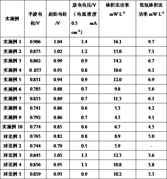
说明:①上述催化剂ORR催化性能参数(包括半波电位、起始电位)是在测试环境为0.1M
KOH碱液环境进行测试,测试时预先通氧气确保溶解氧饱和。测试装置为三电极测试体系,工作电极为涂布催化剂的旋转圆盘电极,对电极为金属铂片,参比电极为Ag/AgCl电极。②体积比功率是在天然海水通氧饱和情况下进行测试(测试海水样品来自天津附近的渤海近海海域)。阳极为2×2×0.5 cm
3的AZ31镁合金块,阴极参照上述各实施例制备。③低氧体积比功率是在溶解氧含量为0.5
mg/L的氧含量下进行测试(测试海水样品来自天津附近的渤海近海海域)。阳极为2×2×0.5 cm
3的AZ31镁合金块,阴极参照上述各实施例制备。
由上表可以看出:①由实施例1与实施例2对比可知,在其他条件相同的情况下,当单原子含量基本一致时,微波处理较之热处理具有更好催化性能。说明微波辐照作用可在双纳米碳之前形成更强的相互接触,加之费米能级差异导致电荷分离现象,从而提高催化活性。
②实施例3与实施例5对比可知,在其他条件相同的情况下,微波处理的功率大小会对催化剂的粒径大小产生影响。实验表明,在微波辐照时长一致的情况下,过高的微波反应器功率,会导致热还原反应速度加快,从而使团聚形成的金属颗粒更大,减小暴露的活性催化面积,导致催化活性下滑;过低的微波功率则会导致催化剂前驱体热解不充分,催化活性差。
③纳米碳之间的比例对催化剂的催化活性有较大的影响,不同纳米碳之间需要调控双纳米碳之间的比例,最优值视具体纳米碳会有不同。
④对于具有ORR催化活性的金属催化剂而言,其金属中心的粒径大小对催化活性具有较大影响。金属催化剂的颗粒越小,暴露的有效接触面积越多,金属利用率越高,更加有利于提高溶解氧利用率,提高催化活性。微波辐照方法由于其超快速升温的特点,较之传统热处理方法,可以大幅缩小反应时长,最大限度减小因长时间加热过程中导致的金属原子迁移和团聚现象的发生,从而更加有利于形成更小粒径的金属颗粒。
⑤利用双纳米碳协同作用较之使用单一碳材料制备,可通过形成电荷分离而使高费米能级的纳米碳端表现出更高的催化活性。同时,这种方法在选用更加经济的碳材料,如活性炭、导电炭黑等,同样可以具有较好的催化活性,显示出该优化策略的普适性。
⑥不同的金属催化中心对实验结果会有较大影响,如铁、钴、镍这类过渡金属中心的催化活性普遍较高。在本实验测试结果表明,铁、钴中心的催化活性较高,是贵金属铂基催化剂的有力替代者。
根据上述说明书的揭示和教导,本发明所属领域的技术人员还可以对上述实施方式进行变更和修改。因此,本发明并不局限于上面揭示和描述的具体实施方式,对本发明的一些修改和变更也应当落入本发明的权利要求的保护范围内。此外,尽管本说明书中使用了一些特定的术语,但这些术语只是为了方便说明,并不对本发明构成任何限制。
Claims (10)
- 一种用于氧还原反应的复合电极材料,其特征在于:包括导电基底材料和涂布于所述导电基底材料表面的催化剂-粘结剂混合材料;所述催化剂-粘结剂混合材料为粘结剂与金属-双纳米碳催化材料的混合固体。
- 根据权利要求1所述的用于氧还原反应的复合电极材料,其特征在于:所述导电基底材料为泡沫镍、钛网、钛合金网、碳纸、碳毡、碳布和碳纤维刷中的一种。
- 根据权利要求1所述的用于氧还原反应的复合电极材料,其特征在于:所述粘接剂为Nafion,或者为Nafion与PTFE、PVDF、PBI、CMC、LA133、SBR、PAA中一种或两种以上的混合物。
- 根据权利要求1所述的用于氧还原反应的复合电极材料,其特征在于:金属-双纳米碳催化材料中,金属占催化材料总质量的0.01% ~ 10%,金属的粒径范围为0.2 ~ 100 nm。
- 根据权利要求1所述的用于氧还原反应的复合电极材料,其特征在于:所述金属-双纳米碳催化材料中,所述金属为Fe、Co、Ni的单一金属或多金属的原子、纳米簇或纳米颗粒。
- 根据权利要求1所述的用于氧还原反应的复合电极材料,其特征在于:所述双纳米碳为石墨烯类、碳纳米管类和活性炭中的两种。
- 根据权利要求6所述的用于氧还原反应的复合电极材料,其特征在于:所述石墨烯类包括氧化石墨烯、氨化石墨烯、还原氧化石墨烯的一种。
- 根据权利要求6所述的用于氧还原反应的复合电极材料,其特征在于:所述碳纳米管类包括单壁碳纳米管、多壁碳纳米管、羟基化碳纳米管、羧基化碳纳米管和石墨化碳纳米管中的一种。
- 一种权利要求1-8任一项所述的用于氧还原反应的复合电极材料的制备方法,其特征在于:至少包括如下步骤:(1)将催化剂前驱体以及两种纳米碳溶解到有机溶剂中,经分散后,烘干得到混合粉末,形成前驱体-纳米碳复合材料;(2)采用程序升温热解法或微波辐照法对前驱体-纳米碳复合材料实现前驱体的热解还原、催化中心的生成和负载以及纳米碳材料间的复合过程,得到金属-双纳米碳复合催化材料;(3)向步骤(2)所得催化材料中加入粘结剂和混溶剂并均匀分散后得到催化剂-粘结剂混合浆料,采用涂布的方法将该混合浆料涂布于导电基底材料中,干燥后得到阴极。
- 根据权利要求9所述的用于氧还原反应的复合电极材料的制备方法,其特征在于,步骤(1)所述催化剂前驱体为Fe、Co、Ni的酞菁类、卟啉类有机大环化合物中的至少一种。11. 根据权利要求9所述的用于氧还原反应的复合电极材料的制备方法,其特征在于,步骤(1)所述两种纳米碳为石墨烯类、碳纳米管类和活性炭类中的两种碳材料的复合物。12. 根据权利要求11所述的用于氧还原反应的复合电极材料的制备方法,其特征在于,所述石墨烯类包括石墨烯、氧化石墨烯、氨化石墨烯、还原氧化石墨烯的一种;所述碳纳米管包括单壁碳纳米管、多壁碳纳米管、羟基化碳纳米管、羧基化碳纳米管、石墨化碳纳米管中的一种;所述活性炭类包括煤质活性炭、木质活性炭和合成材料活性炭中的一种。13. 根据权利要求9所述的用于氧还原反应的复合电极材料的制备方法,其特征在于,步骤(1)中,所述有机溶剂为二甲基亚砜(DMSO)、四氢呋喃(THF)、二甲基甲酰胺(DMF)中的一种;分散方法为机械搅拌、磁力搅拌、超声分散中的一种;烘干方法为旋蒸法、搅拌加热烘干、冷冻干燥法中的一种。14. 根据权利要求9所述的用于氧还原反应的复合电极材料的制备方法,其特征在于,步骤(2)中所述程序升温热解法是将前驱体-纳米碳复合材料置于管式反应炉中,在通保护性气体和/或通还原性气体的情况下,以1 ~ 30 ℃/min的升温速率升温至500 ~ 1200 ℃并加热0.1 ~ 24 h,所述保护性气体为氮气、氩气、氦气中的至少一种,所述还原性气体为氨气、氢气、一氧化碳中的至少一种。15. 根据权利要求9所述的用于氧还原反应的复合电极材料的制备方法,其特征在于,步骤(2)中所述微波辐照法是将前驱体-纳米碳复合材料置于微波反应器中进行微波辐照,功率为800 ~ 1000 W,辐照时长为30 ~ 600 s;此时,所述双纳米碳中包含石墨烯类和碳纳米管类中具有吸波能力的纳米碳的至少一种,所述石墨烯类包括石墨烯和还原氧化石墨烯中的一种;所述碳纳米管类包括单壁碳纳米管、多壁碳纳米管、羟基化碳纳米管、羧基化碳纳米管、石墨化碳纳米管中的一种。16. 根据权利要求9所述的用于氧还原反应的复合电极材料的制备方法,其特征在于,步骤(2)中所得催化材料的比表面积为200 ~ 900 m 2/g,粒径范围0.2 ~ 100 nm。17. 根据权利要求9所述的用于氧还原反应的复合电极材料的制备方法,其特征在于,步骤(3)中,分散方法为机械搅拌、磁力搅拌、超声分散中的至少一种。18. 根据权利要求9所述的用于氧还原反应的复合电极材料的制备方法,其特征在于,步骤(3)中,所述粘结剂为Nafion,或者为Nafion与PTFE、PVDF、PBI、CMC、LA133、SBR、PAA中一种或两种以上的混合物,所述粘接剂占电极材料质量的0.01%-0.5%;所述混溶剂为乙醇或异丙醇,催化剂-粘结剂混合浆料中催化材料浓度为1 mg·mL -1~5 mg·mL -1。19. 如权利要求1所述的用于氧还原反应的复合电极材料的用途:用于溶解氧海水电池。
Applications Claiming Priority (4)
| Application Number | Priority Date | Filing Date | Title |
|---|---|---|---|
| CN202010745303.1 | 2020-07-29 | ||
| CN202010746808.X | 2020-07-29 | ||
| CN202010745303.1A CN111952603B (zh) | 2020-07-29 | 2020-07-29 | 用于氧还原反应的复合电极材料的制备方法 |
| CN202010746808.XA CN112002907B (zh) | 2020-07-29 | 2020-07-29 | 用于氧还原反应的复合电极材料及其用途 |
Publications (1)
| Publication Number | Publication Date |
|---|---|
| WO2022021946A1 true WO2022021946A1 (zh) | 2022-02-03 |
Family
ID=80036825
Family Applications (1)
| Application Number | Title | Priority Date | Filing Date |
|---|---|---|---|
| PCT/CN2021/087403 Ceased WO2022021946A1 (zh) | 2020-07-29 | 2021-04-15 | 用于氧还原反应的复合电极材料、制备方法及其用途 |
Country Status (1)
| Country | Link |
|---|---|
| WO (1) | WO2022021946A1 (zh) |
Cited By (3)
| Publication number | Priority date | Publication date | Assignee | Title |
|---|---|---|---|---|
| CN114976484A (zh) * | 2022-07-11 | 2022-08-30 | 大连理工大学 | 负载Ni2P-Co肖特基节活性位点海胆状碳材料电催化剂、制备方法及其应用 |
| CN116632232A (zh) * | 2023-05-29 | 2023-08-22 | 广西金茂钛业股份有限公司 | 一种利用磷酸铁制备磷酸铁锂正极材料的方法 |
| CN119491223A (zh) * | 2025-01-17 | 2025-02-21 | 山东龙安泰环保科技有限公司 | 一种bdd高性能极板材料及其制备方法 |
Citations (6)
| Publication number | Priority date | Publication date | Assignee | Title |
|---|---|---|---|---|
| CN101916866A (zh) * | 2010-08-02 | 2010-12-15 | 北京交通大学 | 复合碳材料为载体的燃料电池催化剂及制备方法 |
| CN103050714A (zh) * | 2011-10-17 | 2013-04-17 | 中国科学院大连化学物理研究所 | 一种燃料电池用掺杂纳米碳电催化剂及其应用 |
| CN107256973A (zh) * | 2017-06-30 | 2017-10-17 | 天津工业大学 | 一种三维结构石墨烯‑碳纳米管复合载体负载PtSn催化剂的制备方法 |
| CN109097788A (zh) * | 2018-08-10 | 2018-12-28 | 复旦大学 | 一种双碳耦合过渡金属镍基量子点电催化剂及其制备方法 |
| CN111952603A (zh) * | 2020-07-29 | 2020-11-17 | 天津大学 | 用于氧还原反应的复合电极材料的制备方法 |
| CN112002907A (zh) * | 2020-07-29 | 2020-11-27 | 天津大学 | 用于氧还原反应的复合电极材料及其用途 |
-
2021
- 2021-04-15 WO PCT/CN2021/087403 patent/WO2022021946A1/zh not_active Ceased
Patent Citations (6)
| Publication number | Priority date | Publication date | Assignee | Title |
|---|---|---|---|---|
| CN101916866A (zh) * | 2010-08-02 | 2010-12-15 | 北京交通大学 | 复合碳材料为载体的燃料电池催化剂及制备方法 |
| CN103050714A (zh) * | 2011-10-17 | 2013-04-17 | 中国科学院大连化学物理研究所 | 一种燃料电池用掺杂纳米碳电催化剂及其应用 |
| CN107256973A (zh) * | 2017-06-30 | 2017-10-17 | 天津工业大学 | 一种三维结构石墨烯‑碳纳米管复合载体负载PtSn催化剂的制备方法 |
| CN109097788A (zh) * | 2018-08-10 | 2018-12-28 | 复旦大学 | 一种双碳耦合过渡金属镍基量子点电催化剂及其制备方法 |
| CN111952603A (zh) * | 2020-07-29 | 2020-11-17 | 天津大学 | 用于氧还原反应的复合电极材料的制备方法 |
| CN112002907A (zh) * | 2020-07-29 | 2020-11-27 | 天津大学 | 用于氧还原反应的复合电极材料及其用途 |
Cited By (4)
| Publication number | Priority date | Publication date | Assignee | Title |
|---|---|---|---|---|
| CN114976484A (zh) * | 2022-07-11 | 2022-08-30 | 大连理工大学 | 负载Ni2P-Co肖特基节活性位点海胆状碳材料电催化剂、制备方法及其应用 |
| CN114976484B (zh) * | 2022-07-11 | 2023-04-11 | 大连理工大学 | 负载Ni2P-Co肖特基结活性位点海胆状碳材料电催化剂、制备方法及其应用 |
| CN116632232A (zh) * | 2023-05-29 | 2023-08-22 | 广西金茂钛业股份有限公司 | 一种利用磷酸铁制备磷酸铁锂正极材料的方法 |
| CN119491223A (zh) * | 2025-01-17 | 2025-02-21 | 山东龙安泰环保科技有限公司 | 一种bdd高性能极板材料及其制备方法 |
Similar Documents
| Publication | Publication Date | Title |
|---|---|---|
| CN111952603B (zh) | 用于氧还原反应的复合电极材料的制备方法 | |
| Huang et al. | Atomic modulation and structure design of carbons for bifunctional electrocatalysis in metal–air batteries | |
| Zhong et al. | Highly conductive skeleton Graphitic-C3N4 assisted Fe-based metal-organic frameworks derived porous bimetallic carbon nanofiber for enhanced oxygen-reduction performance in microbial fuel cells | |
| Zhang et al. | Manganese dioxide-coated carbon nanotubes as an improved cathodic catalyst for oxygen reduction in a microbial fuel cell | |
| Yang et al. | Dynamically-evolved surface heterojunction in iridium nanocrystals boosting acidic oxygen evolution and overall water splitting | |
| Wang et al. | Novel g-C3N4 assisted metal organic frameworks derived high efficiency oxygen reduction catalyst in microbial fuel cells | |
| Li et al. | ZIF-8@ ZIF-67–derived ZnCo2O4@ nitrogen–doped carbon/carbon nanotubes wrapped by a carbon layer: a stable oxygen reduction catalyst with a competitive strength in acid media | |
| WO2022021946A1 (zh) | 用于氧还原反应的复合电极材料、制备方法及其用途 | |
| CN108172847A (zh) | 酞菁铁基碳纳米管复合电催化剂及其制备方法和用途 | |
| Yang et al. | Cobalt oxides nanoparticles supported on nitrogen-doped carbon nanotubes as high-efficiency cathode catalysts for microbial fuel cells | |
| CN112002907B (zh) | 用于氧还原反应的复合电极材料及其用途 | |
| CN108615959A (zh) | 一种溶解氧海水电池的亲水阴极及其制备和应用 | |
| Samawi et al. | Single-atom cobalt encapsulated in carbon nanotubes as an effective catalyst for enhancing sulfur conversion in lithium–sulfur batteries | |
| CN111871406A (zh) | 一种电化学还原二氧化碳制合成气的催化剂及其制备方法 | |
| CN111841598B (zh) | 一种具有高析氧催化活性的S掺杂Co@NC复合材料及其制备方法 | |
| Yang et al. | The exceptional performance of polyhedral porous carbon embedded nitrogen-doped carbon networks as cathode catalyst in microbial fuel cells | |
| Peng et al. | NiCo alloy nanoparticles anchored on carbon nanotube-decorated carbon nanorods as a durable and efficient oxygen electrocatalyst for zinc-air flow batteries | |
| Chen et al. | Enhanced oxygen evolution and power density of Co/Zn@ NC@ MWCNTs for the application of zinc-air batteries | |
| Cao et al. | Super-assembled carbon nanofibers decorated with dual catalytically active sites as bifunctional oxygen catalysts for rechargeable Zn-air batteries | |
| Guan et al. | Multistage structural self-supported electrode via structural engineering on carbon nanofibers for efficient hydrogen evolution reaction at high current density | |
| CN112768706B (zh) | 一种核壳催化剂及其制备方法与在可充电锌空电池中的应用 | |
| Di et al. | Hierarchical porous N-doped carbon-supported PtCu nanoparticles as an efficient catalyst for oxygen reduction reaction | |
| Huang et al. | N-doped carbon nanosheets derived from lignin as a novel bifunctional electrocatalyst for rechargeable zinc-air battery | |
| Chen et al. | Heteroepitaxial metal-organic frameworks derived cobalt and nitrogen codoped carbon nanosheets to boost oxygen reduction | |
| Ma et al. | Porous carbon nanosheets integrated with graphene-wrapped CoO and CoNx as efficient bifunctional oxygen electrocatalysts for rechargeable zinc-air batteries |
Legal Events
| Date | Code | Title | Description |
|---|---|---|---|
| 121 | Ep: the epo has been informed by wipo that ep was designated in this application |
Ref document number: 21848681 Country of ref document: EP Kind code of ref document: A1 |
|
| NENP | Non-entry into the national phase |
Ref country code: DE |
|
| 122 | Ep: pct application non-entry in european phase |
Ref document number: 21848681 Country of ref document: EP Kind code of ref document: A1 |