WO2022019840A1 - Unitary horn antenna - Google Patents
Unitary horn antenna Download PDFInfo
- Publication number
- WO2022019840A1 WO2022019840A1 PCT/SG2021/050430 SG2021050430W WO2022019840A1 WO 2022019840 A1 WO2022019840 A1 WO 2022019840A1 SG 2021050430 W SG2021050430 W SG 2021050430W WO 2022019840 A1 WO2022019840 A1 WO 2022019840A1
- Authority
- WO
- WIPO (PCT)
- Prior art keywords
- antenna
- unitary device
- horn
- horn antenna
- separate waveguides
- Prior art date
- Legal status (The legal status is an assumption and is not a legal conclusion. Google has not performed a legal analysis and makes no representation as to the accuracy of the status listed.)
- Ceased
Links
Classifications
-
- B—PERFORMING OPERATIONS; TRANSPORTING
- B22—CASTING; POWDER METALLURGY
- B22F—WORKING METALLIC POWDER; MANUFACTURE OF ARTICLES FROM METALLIC POWDER; MAKING METALLIC POWDER; APPARATUS OR DEVICES SPECIALLY ADAPTED FOR METALLIC POWDER
- B22F10/00—Additive manufacturing of workpieces or articles from metallic powder
- B22F10/20—Direct sintering or melting
-
- B—PERFORMING OPERATIONS; TRANSPORTING
- B33—ADDITIVE MANUFACTURING TECHNOLOGY
- B33Y—ADDITIVE MANUFACTURING, i.e. MANUFACTURING OF THREE-DIMENSIONAL [3D] OBJECTS BY ADDITIVE DEPOSITION, ADDITIVE AGGLOMERATION OR ADDITIVE LAYERING, e.g. BY 3D PRINTING, STEREOLITHOGRAPHY OR SELECTIVE LASER SINTERING
- B33Y80/00—Products made by additive manufacturing
-
- H—ELECTRICITY
- H01—ELECTRIC ELEMENTS
- H01P—WAVEGUIDES; RESONATORS, LINES, OR OTHER DEVICES OF THE WAVEGUIDE TYPE
- H01P1/00—Auxiliary devices
- H01P1/16—Auxiliary devices for mode selection, e.g. mode suppression or mode promotion; for mode conversion
- H01P1/161—Auxiliary devices for mode selection, e.g. mode suppression or mode promotion; for mode conversion sustaining two independent orthogonal modes, e.g. orthomode transducer
-
- H—ELECTRICITY
- H01—ELECTRIC ELEMENTS
- H01Q—ANTENNAS, i.e. RADIO AERIALS
- H01Q13/00—Waveguide horns or mouths; Slot antennas; Leaky-waveguide antennas; Equivalent structures causing radiation along the transmission path of a guided wave
- H01Q13/02—Waveguide horns
- H01Q13/0208—Corrugated horns
-
- H—ELECTRICITY
- H01—ELECTRIC ELEMENTS
- H01Q—ANTENNAS, i.e. RADIO AERIALS
- H01Q13/00—Waveguide horns or mouths; Slot antennas; Leaky-waveguide antennas; Equivalent structures causing radiation along the transmission path of a guided wave
- H01Q13/02—Waveguide horns
- H01Q13/0283—Apparatus or processes specially provided for manufacturing horns
- H01Q13/0291—Apparatus or processes specially provided for manufacturing horns for corrugated horns
-
- C—CHEMISTRY; METALLURGY
- C25—ELECTROLYTIC OR ELECTROPHORETIC PROCESSES; APPARATUS THEREFOR
- C25D—PROCESSES FOR THE ELECTROLYTIC OR ELECTROPHORETIC PRODUCTION OF COATINGS; ELECTROFORMING; APPARATUS THEREFOR
- C25D1/00—Electroforming
- C25D1/02—Tubes; Rings; Hollow bodies
-
- C—CHEMISTRY; METALLURGY
- C25—ELECTROLYTIC OR ELECTROPHORETIC PROCESSES; APPARATUS THEREFOR
- C25D—PROCESSES FOR THE ELECTROLYTIC OR ELECTROPHORETIC PRODUCTION OF COATINGS; ELECTROFORMING; APPARATUS THEREFOR
- C25D5/00—Electroplating characterised by the process; Pretreatment or after-treatment of workpieces
- C25D5/54—Electroplating of non-metallic surfaces
- C25D5/56—Electroplating of non-metallic surfaces of plastics
-
- G—PHYSICS
- G06—COMPUTING OR CALCULATING; COUNTING
- G06N—COMPUTING ARRANGEMENTS BASED ON SPECIFIC COMPUTATIONAL MODELS
- G06N3/00—Computing arrangements based on biological models
- G06N3/12—Computing arrangements based on biological models using genetic models
- G06N3/126—Evolutionary algorithms, e.g. genetic algorithms or genetic programming
-
- Y—GENERAL TAGGING OF NEW TECHNOLOGICAL DEVELOPMENTS; GENERAL TAGGING OF CROSS-SECTIONAL TECHNOLOGIES SPANNING OVER SEVERAL SECTIONS OF THE IPC; TECHNICAL SUBJECTS COVERED BY FORMER USPC CROSS-REFERENCE ART COLLECTIONS [XRACs] AND DIGESTS
- Y02—TECHNOLOGIES OR APPLICATIONS FOR MITIGATION OR ADAPTATION AGAINST CLIMATE CHANGE
- Y02P—CLIMATE CHANGE MITIGATION TECHNOLOGIES IN THE PRODUCTION OR PROCESSING OF GOODS
- Y02P10/00—Technologies related to metal processing
- Y02P10/25—Process efficiency
Definitions
- the present invention relates, in general terms, to a unitary horn antenna, and also relates to methods of manufacturing and designing the horn antenna.
- the corrugated horn and OMT could be devised by analytical methods. But for compact and irregular configurations, a more versatile approach is iterative optimization with initial values derived by theory and experience. Optimizer- based design methods gain increasing attention in electronic engineering. Recently, a novel nature-inspired algorithm, the grey wolf optimizer (GWO), was introduced to antenna design and array synthesis. Due to its concise framework and excellent performance, the GWO has been adopted in diverse fields. However, for electromagnetic design problems, studies in this optimizer are insufficient. Exclusive modifications on the GWO are demanded to reduce simulation cost and accelerate convergence.
- GWO grey wolf optimizer
- a unitary device comprising a horn antenna disposed about a horn axis and having an engineered inner surface; and an integrated orthomode transducer comprising a waveguide transition and at least two separate waveguides each having an internal surface, the waveguide transition connecting the at least two separate waveguides to the antenna, wherein the orthogonal transducer is adapted to couple at least two orthogonal linear polarized fields from the at least two separate waveguides into the waveguide transition for transmission by the antenna, and/or decouple at least two orthogonal linear polarized fields received by the waveguide transition from the antenna into respective ones of the at least two separate waveguides.
- the inner surface of the horn antenna is designed according to a broad class of optimisation algorithms.
- the internal surface of at least one of the at least two separate waveguides is designed according to a broad class of optimisation algorithms.
- the horn antenna has a circular cross-section.
- the horn antenna has a square cross-section.
- the horn antenna is adapted to support two or more waveguide modes corresponding to the at least two orthogonal linear polarized fields.
- the horn antenna operates in 12.25-12.75 GHz and 14- 14.5 GHz.
- the waveguide transition is a quasi-elliptical waveguide transition connecting a rectangular and a circular waveguide.
- the inner surface of the horn antenna comprises a plurality of ridges, each ridge having a horizontal ridge width, being oriented parallel to the horn axis, with the ridge being located at slots along the inner surface of the horn antenna, each slot having a vertical slot height, and a horizontal slot width, being oriented parallel to the horn axis.
- the horn antenna has a flare angle being the angle between a line drawn parallel to the horn axis and a line passing through a top surface of adjacent ones of said ridges.
- the unitary device according is formed from at least one of a metal material and a plastic material.
- the waveguide transition tapers away from the horn antenna.
- the at least one of the at least two of the separate waveguides has a rectangular cross-section.
- the at least one of the at least two of the separate waveguides has a circular cross-section.
- the at least one of the at least two of the separate waveguides has a waveguide axis at a non-zero angle to the horn axis.
- a length of the at least one of the at least two of the separate waveguides is formed from a sequence of sections, each section having a length, width and height, and varying from each adjacent said section in the sequence, in at least one of the length, width and height.
- an antenna assembly comprising a unitary device; a perforated reflector; and a platform for stabilizing the utility device and the perforated reflector, wherein the horn antenna of the unitary device functions as the feed for the perforated reflector, and a phase center of the horn antenna of the unitary device is at a focus of the perforated reflector.
- a manufacturing method for manufacturing the antenna assembly according to 17, comprising manufacturing at least one of the unitary device, the perforated reflector, and the platform using three-dimensional printing technology.
- a manufacturing method for manufacturing the unitary device according comprising manufacturing the unitary device in at least two separate blocks.
- the manufacturing method further comprises at least one of manufacturing each part of the at least two separate blocks as one or more of external protrusions, holes and partially holes; and providing alignment pins and threaded holes on the at least two separate blocks to facilitate assembly.
- a method of designing the horn antenna or the separate waveguides of the orthomode transducer based on grey wolf optimizer comprising generating initialization population in a pre-defined solution space; calculating a fitness value of each grey wolf in the initialization population according to a pre-defined fitness function, each grey wolf defining a solution at a position in the solution space; and repeatedly: selecting a predetermined number of fitness values based on an ordering of fitness values from large to small (“best fitness values"), and identifying and storing as X a , Xp, and Xa a position of each best fitness value based on the respective grey wolf; updating and storing position for each grey wolf according to one or more pre-defined functions; and updating and storing the fitness value of each grey wolf in each updated position according to the pre-defined fitness function; and outputting Xa when a predetermined maximum number of repetitions is reached.
- the method further comprises comparing the updated position with each position of a previous repetition, to determine whether or not to update the fitness value with the updated position.
- the fitness function for designing the horn antenna according to any one of 1 to 7 is determined according to: in which D denotes a positive weighted coefficient, u(x) denotes step function, Sii max(i) is maximum Sn parameter in dB in the operating band, c n denotes the horizontal interval width for the n-th interval.
- Figure 1(a) shows an example horn that is directly carved out of a metallic puck through a milling machine
- Figure 1(b) shows an example horn where the inner and outer parts are fabricated separately
- Figure 1(c) shows an example horn that is halved into two identical parts from the symmetrical plane to facilitate fabrication
- Figure 2(a) shows an example dielectric horn antenna
- Figure 2(b) and (2c) show an example plastic horn that is halved into two parts
- Figure 3(a) and 3(b) shows an example metallic horn and its OMT
- Figure 4(a) through 4(e) illustrates an example unitary device comprising a horn antenna and an integrated orthomode transducer comprising a waveguide transition and at least two separate waveguides;
- Figure 5(a) through(c) shows an example antenna assembly, comprising a unitary device, a perforated reflector, and a platform;
- Figure 6 illustrates an example optimization process for designing the corrugated horn antenna or the separate waveguides of the orthomode transducer based on grey wolf optimizer
- Figure 7 illustrates an optimization result using the optimization process in Figure 5;
- Figure 8(a) through(e) show the performance of the horn of Figure 5;
- Figure 9 illustrates the comparison between the original and modified encircling coefficients;
- Figure 10 illustrates an example optimization process for designing the corrugated horn antenna or the separate waveguides of the orthomode transducer based on grey wolf optimizer
- Figure 11 shows the comparison between GWO and MGWO based on Opt II in Table IV;
- Figure 12(a) through(d) illustrates optimization results using the optimization process in Figure 10 based on Opt I-IV in Table IV;
- Figure 13(a) illustrates comparison between GWO and MGWO based on Opt II in Table IV regarding average achievable cost value after each iteration
- Figure 13(b) illustrates comparison between GWO and MGWO based on Opt II in Table IV regarding average required iteration to achieve certain cost value
- Figure 14(a) and(b) illustrate fabricated integrated dual-band design horn antenna HI and wideband design antenna H2 with adaptors, respectively;
- Figure 15(a) and(b) illustrate simulated and measured S parameters for dual band antenna HI and wideband antenna H2, respectively;
- Figure 15(a) through(d) illustrates simulated and measured radiated patterns for E-plane pattern at 12.5 GHz, H-plane pattern at 12.5 GHz, E-plane pattern at 14.25 GHz, H-plane pattern at 14.25 GHz.
- the present disclosure relates to a unitary device comprising a compact light- weighted dual-band dual-polarized horn antenna.
- the horn is adapted to work with two orthogonal polarizations for receiving and transmitting, respectively.
- the proposed antenna functions as a feed horn of a reflector for Ku-band satellite communications. It will be appreciated that the antenna could work in dual bands, for example 12.25-12.75 GHz and 14-14.5 GHz.
- the proposed antenna is a dual-polarized antenna horn with an integrated orthomode transducer orthomode transducer (OMT) presented for satellite communications.
- OMT orthomode transducer orthomode transducer
- the proposed OMT is applied as the feeding structure, and is with a tilted branch which is integrated below the horn so that separate fabrication and redundant structures are not needed.
- the integrated structure increases its versatility and reliability in severe scenarios.
- the proposed unitary device comprises an automatically designed all-integrated three-dimensional (3D)-printed horn antenna.
- the configuration of the antenna structure is compatible with direct 3D metal printing technology.
- An integrated antenna structure suitable for direct printing is devised and validated. Material waste caused by the auxiliary supports during printing is minimized. Assembly, aligning, and fixtures are also unnecessary, resulting in compactness.
- Such an antenna albeit as an all-metal structure, has a light weight of 200 g. It will be appreciated that this integrated antenna can be readily fabricated through a 3D printer all in once.
- a corrugated horn can be adopted as the aperture antenna. This type of horn is broadly used for its excellent beam equalization in E-, H-, and diagonal planes, and a steady phase center.
- unitary refers to the device being fabricated as a single component or item.
- a “unitary device” will comprise the horn antenna and integrated OMT formed together as a single component or item. Such a unitary device (100) is shown in Figure 4.
- the unitary device 100 comprises: a horn antenna (102) disposed about a horn axis and having an engineered inner surface; and an integrated OMT comprising a waveguide transition (106) and at least two separate waveguides (108 and 110) each having an internal surface, the waveguide transition 106 connecting the at least two separate waveguides 108 and 110 to the antenna 102, wherein the OMT 104 is adapted to couple at least two orthogonal linear polarized fields from the at least two separate waveguides into the waveguide transition for transmission by the antenna 102, and/or decouple at least two orthogonal linear polarized fields received by the waveguide transition from the antenna 102 into respective ones of the at least two separate waveguides 108 and 110.
- Figure 4(d) illustrates the structure of the horn 102.
- the corrugated horn 102 with four vertical slots (112) is chosen (see Figure 4(d)).
- the inner surface of the horn antenna 102 comprises a plurality of ridges (114) (see Figure 2(d)), each ridge having a horizontal ridge width (i.e., d lf d 3l d 5r and d 7 ), being oriented parallel to the horn axis, with the ridge being located at slots 112 along the inner surface of the horn antenna, each slot having a vertical slot height (i.e., l lr l 2 , and Z 4 ), and a horizontal slot width (i.e., d 2 r d 4r d 6r and d 8 ), being oriented parallel to the horn axis.
- the horn antenna 102 also has a flare angle (i.e., (p h ) being the angle between a line drawn parallel to the horn
- the OMT consists of a tapering transition 106, a direct branch 108, and a tilted one 110.
- the waveguide transition 106 is a quasi-elliptical waveguide transition connecting a rectangular (i.e., 108) and a circular waveguide (i.e., 110). In some embodiments, said 106 is designed to taper away from the horn antenna 102.
- the at least one of 108 and 110 has a circular cross- section. In some other embodiments, the at least one of 108 and 110 has a rectangular cross-section.
- Said titled branch 110 has a waveguide axis at a non zero angle to the horn axis (see Figure 4(e)).
- said tilted branch 110 may be formed from a sequence of sections (116), each section having a length (i.e., a lf a 2 , a 3 , and a 4 ), width (i.e., b lr b 2r b 3r and b 4 ) and height (i.e., c lf c 2 , c 3 , and c 4 ), and varying from each adjacent said section in the sequence, in at least one of the length, width and height.
- the tilted one 110 adopts a four-step configuration (see Figure 4(b)) for impedance matching.
- the performance of the horn and OMT hardly influences each other so that they are optimized independently as illustrated in Figure 4(c).
- the inner surface of the horn antenna 102 is designed according to a broad class of optimization algorithms, which will discussed in full details.
- the internal surface of at least one of the at least two separate waveguides is designed according to a broad class of optimization algorithms.
- a corrugated horn with various types of cross-sections and slots is preferred.
- the horn 102 has a circular cross-section.
- the horn has a square cross-section.
- the disclosure herein may be made generally with reference to horn antennae having a corrugated inner surface.
- other engineered inner surfaces may be used - e.g. flat, undulating, slotted, grooved, paraboloid, hyperboloid, spheroid and any other inner surface shape or arrangement necessary to achieve a particular and desired purpose.
- the horn antenna is adapted to support two or more waveguide modes corresponding to the at least two orthogonal linear polarized fields.
- the horn antenna operates in 12.25-12.75 GHz and 14-14.5 GHz.
- the horn antenna 102 may work with two orthogonal linear polarizations for receiving and transmitting modes, respectively.
- the OMT is widely applied as the feeding structure.
- the design of the corrugated horn 102 and its OMT could base on analytical analysis in limited cases. As will be discussed in more details, a more versatile method is to conduct iterative optimization in light of the performance requirement. For compact designs where a short corrugated horn only has 3-4 slots and its OMT is irregular, a powerful optimizer is highly required. The designer may set the initial configuration of the antenna according to analytical and empirical equations, or directly launch the optimizer with random initial values. This design process is automated, which significantly saves time and human costs.
- FIG. 5(b) shows an example antenna assembly (500), comprising the unitary device 100, a perforated reflector (502), and a platform (504).
- the device 100 here is equipped on the platform 504 with the help of a choking fixture (506) and a pad (508) below.
- the platform 504 is used for stabilizing the utility device 100 and the perforated reflector 502.
- the horn antenna of the unitary device functions as the feed for the perforated reflector 502.
- the device 100 has an angle (i.e., qo) being the angle between a line drawn parallel to the platform axis and a line passing through the centre of the reflector 502. Said angle qo is set such that a phase centre of the horn antenna 102 of the unitary device 100 is at a focus of the perforated reflector 502.
- the design of the antenna configuration in the present disclosure follows two principles.
- the first principle is that the structure needs to be compatible with direct 3D printing, where assembly is not required. All suspended part should have a tilted angle of no more than 45° so that it does not collapse during fabrication.
- Said 3D printing is a potential candidate to substitute the traditional machining process in horn antenna manufacturing.
- the size and weight of the antenna 102 can be significantly reduced, which saves much fabrication time and cost.
- two types of techniques can be applied— plastic and metal 3D printing.
- plastic printing a dielectric horn antenna is printed first ( Figure 2(a)). Then, electroplating, conductive spray paint, or metal coating is conducted to achieve metallization.
- a dielectric horn antenna is printed first ( Figure 2(a)).
- electroplating, conductive spray paint, or metal coating is conducted to achieve metallization.
- the plastic horn is always halved into two parts, as seen in Figure 2(b) and Figure 2(c).
- the whole fabrication process
- Another possible 3D printing method is based on metallic material, especially the aluminium alloy AISiioMg.
- the horn antenna is directly printed layer by layer through additive manufacturing. Nevertheless, the structure for metal printing cannot be arbitrary. Suspended stubs longer than several millimetres are usually not feasible unless redundant support is used. Likely, the tilted angle of the structure should not exceed 45° to avoid collapsing due to gravity. Therefore, the metallic horn and its OMT are printed separately to increase design freedom. Flanges with screw holes are needed for fixing, which increases the antenna volume and impairs its stability and sealing performance.
- the antenna assembly 500 as a whole can be manufactured using 3D printing technology.
- the antenna assembly 500 especially the unitary device 100 is formed from at least one of a metal material and a plastic material.
- the unitary device and/or assembly may be manufactured in at least two separate block.
- the unitary device is manufactured by manufacturing the antenna 102 and OMT separately.
- the unitary device 100 is manufactured by manufacturing the antenna 102, the waveguide transition 106 and the waveguides 108 and 110 separately. It will be appreciated that alignments pins and threaded holes can be provided on the separate blocks to facilitate assembly.
- the second principle for the design of the antenna configuration is that the configuration needs to be easy to optimize, which means that the dimension of the solution space should be minimized.
- an optimization problem is constructed to design the antenna automatically based on Matlab-HFSS co-simulation.
- the impedance matching, radiation pattern, cross-polarization level (XPL), and antenna size are considered.
- the antenna 102 is designed as the feed of a reflector for Ku-band satellite communications. Therefore, the operating band, gain, cross-polarization level (XPL), and beamwidth in E-, H-, and diagonal planes need optimization.
- the size of the antenna is optimized as well for compactness.
- the proposed automated design process bases on a modified GWO which will be demonstrated later.
- the original GWO is a single-objective algorithm. Its multi-objective versions were proposed, which is not necessary in this disclosure.
- a fitness function for OptHorn is put forward in (1). It consists of five components representing the wanted radiation behaviors, input characteristics, and antenna size.
- u(x) denotes step function
- Sn_max(m) is maximum Sn parameter in dB in the m-th band
- Bandwidth i2 d e(i,j) and XPL(i,j) are the 12dB beamwidth in degree and cross-polarization level in dB, respectively, in the ⁇ -th plane at the /- th frequency
- d k denotes the horizontal ridge width and the horizontal slot width in mm
- dtotai is size limitation of the horizontal ridge width and the horizontal slot width.
- the fitness function of OptOMT is set as: where D is a positive weighted coefficient, u(x) is the step function, Su m a x is the maximum Sn parameter in dB in the operating band, C k is the OMT parameter in mm shown in Figure 4(e), and Ctotai represents the size limitation of the OMT.
- D is a positive weighted coefficient
- u(x) is the step function
- Su m a x is the maximum Sn parameter in dB in the operating band
- C k is the OMT parameter in mm shown in Figure 4(e)
- Ctotai represents the size limitation of the OMT.
- an algorithm-based design method is proposed for said Ku-band satellite communications.
- the whole structure of the proposed horn antenna is automatically designed through a swarm intelligence-based algorithm, i.e., the GWO, to obtain fine antenna performance and compact size.
- the GWO was proposed in 2014. With a concise framework, it shows competitive or even superior performance when compared with classical global optimization algorithms, such as the genetic algorithm, particle swarm optimization, differential evolution, etc. It has been proved that this optimizer has great potential in electromagnetics.
- a compact antenna structure is put forward, of which the design process is decomposed into two sub-problems to accelerate optimization.
- the original GWO is modified exclusively for electromagnetic design problems so that the time cost is reduced.
- the GWO shows excellent performance, which coincides with the result.
- the maximal Sll parameter obtained by the GWO already reaches -15 dB in the two bands.
- the value is further optimized to -20 dB. Since the optimization processes of the horn and OMT are in parallel, the overall design time can be reduced to one day.
- Figure 6 illustrates an example optimization method 600 for designing the corrugated horn antenna or the separate waveguides of the orthomode transducer based on GWO.
- the method 600 comprises:
- Step 602 generating initialization population in a pre-defined solution space
- Step 604 calculating a fitness value of each grey wolf in the initialization population according to a pre-defined fitness function, each grey wolf defining a solution at a position in the solution space; and Step 606: repeatedly: selecting a predetermined number of fitness values based on an ordering of fitness values from large to small ("best fitness values"), and identifying and storing as X a , Xp, and Xaa position of each best fitness value based on the respective grey wolf; updating and storing position for each grey wolf according to one or more pre-defined functions; and updating and storing the fitness value of each grey wolf in each updated position according to the pre-defined fitness function; and Step 608: outputting X a when a predetermined maximum number of repetitions is reached.
- This GWO algorithm is inspired by the social hierarchy and group hunting mechanism of grey wolves.
- the method further comprises comparing the updated position with each position of a previous repetition, to determine whether or not to update the fitness value with the updated position.
- This algorithm showed supreme performance in nonlinear and nonconvex continuous-value problems with a high-dimensional solution space. It has also been evaluated and compared with other classical algorithms in a comprehensive manner. To explain the design process, an example is presented in Table III. The integrated antenna is divided into two parts, the horn and OMT, as seen in Figure 4(c). This simplifies the optimization problem by dividing it into two sub-problems and reducing the dimension of the solution space.
- the variables for optimization are illustrated in Figure 4(d) and(e), and Table I.
- the antenna is optimized to have compact size and required performance, in terms of beam widths in E-, H-, and diagonal planes; and voltage standing wave ratio (VSWR) or reflection coefficient.
- the optimization starts with a set of random initial variables.
- the goal of the algorithms in Figure 6 is to minimize the value of the objective functions in Table III.
- GWO has a concise mechanism, low memory requirement, and excellent performance, according to the no free lunch theorem, exclusive modifications still conduce to improving its performance in actual applications. Therefore, a modified GWO (MGWO) is proposed in the present invention for electromagnetic (EM) automated design in light of the principles below.
- EM electromagnetic
- said MGWO with reduced hunting expanse, enhanced solution robustness, an adaptive step size, sample filtering, and re-initialization is proposed to automate and shorten the design process.
- the whole structure is divided into two independent parts to simplify the optimization problem.
- the performance and size of the antenna are simultaneously optimized.
- the configuration of the antenna is highly compatible with direct 3D printing technology so that separate fabrication is not needed. Redundant aligning, supporting, or fixing structures are also eliminated as much as possible for compactness.
- a 3D-printed all-integrated horn antenna is fabricated and measured. It is then equipped to a reflector.
- the GWO mimics the social hierarchy and hunting behavior of grey wolves. It uses the top three historical solutions (alpha, beta, and delta wolves, i.e., the top three historical solutions) to estimate the position of the temporary optimum and guide the searching behavior and to lead the wolf group to search for the prey (optimum).
- the operator for variable updating is referred to as "encircling”.
- the searching behavior is depicted by where x(t+2) and x(t) are the position vectors of one wolf in (t+1)- th and t-th iterations, xp(t) is the assumed optimum, and A and C are two diagonal matrices defined as:
- Ri and R2 are two diagonal matrices of which elements have random values between [0, 1]
- I is the identity matrix
- the position of each wolf is updated according to the best three historical positions (alpha, beta, and delta wolves) through the encircling operator, that is: where x,(t+l) and x,(t) are the position vectors of the / h wolf in the (H-l) th and f th iterations, and x 0 b, s, is the position of the current alpha, beta, and delta wolve, and x, is the position vector of the omega wolf.
- the searching region is discretized, and repetitive searches are forbidden.
- the hunting expanse thus diminishes. Meanwhile, individual wolves are not encouraged to search for the prey around a poor position, which eliminates the solutions that are hypertensive to fabrication and simulation errors.
- an optimization goal is introduced so that the algorithm may stop in advance.
- the original GWO is designed to minimize the cost function.
- the only stop criterion is the total iteration number, implying that the optimization goal is minus infinity.
- Eq.(9) during the exploration stage, if an excellent solution is just a tiny step away from a poor one, it is not adopted due to lack of robustness. Hence, Eq.(9) also eliminates the solutions that are hypertensive to fabrication and simulation errors. This advantage especially applies to 3D-printed horns and OMTs with multiple structural discontinuities. Besides, each element in the positions vector x is rounded off according to the available manufacture precision from the vendor, which discretizes the solution space for less simulation cost and more robustness.
- the initialization course of the GWO is modified to improve the exploration behavior by avoiding sample aggregation.
- the GWO starts with a set of stochastic variables within the solution space, but their even distribution is not well guaranteed.
- a filtering process similar to (9) is thus inserted after the initialization through: then, x . is re-initialized. , . . ,
- an integrated horn antenna that is compatible with metal 3D printing is designed.
- the design takes a balance between antenna performance and size. No extra procedures, such as assembly, surface processing, alignment, or fixing are needed. Hence, the fabrication time and cost are minimized. Besides, the volume of the antenna is reduced through optimization.
- the overall height is around 4lo (96 mm), where lo is the wavelength in free space at the center frequency (12.5 GHz) of the lower band. It is light-weighted and more than 30 percent smaller than the compact machining-based horn antenna operating in the same frequency band in the latest publication. Without screws, the mechanical stability of this succinct structure against severe temperature changes and vibration is excellent.
- the horn antenna functions as the feed for an offset-fed reflector, as seen in Figure 7. It is equipped on a shared platform seen in Figure 7(b) with the help of a choking fixture and a pad below, as shown in Figure 7(a).
- the reflector and platform are also implemented through 3D printing.
- the reflector is densely perforated to reduce the weight of the whole system.
- the platform stabilizes the antennas and guarantee that the phase center of the feed is at the focus of the reflector.
- the configuration of the offset-fed reflector antenna is shown in Figure 7(c).
- the performance of the antenna is shown in Figure 8. It operates in two separate bands in the Ku band with impressive beam equalization in three vertical sections, as presented in Figure 8(a)-(c).
- the radiation performance is steady with respect to frequency. After it is equipped to the reflector platform, good radiation behaviors at the two frequencies are still maintained, as shown in Figure 8(d) and (e). Due to the stable phase center of the horn antenna, the aperture efficiency of the reflector is 72.66% and 75.67% at 12.5 GHz and 14.25 GHz, respectively.
- Figure 10(a) illustrates an example optimization method 1000 for designing the corrugated horn antenna or the separate waveguides of the orthomode transducer based on MGWO.
- the method 1000 comprises:
- Step 1002 generating initialization population in a pre-defined solution space
- Step 1004 calculating a fitness value of each grey wolf in the initialization population according to Eq.(ll), each grey wolf defining a solution at a position in the solution space;
- Step 1006 repeatedly: selecting a predetermined number of fitness values based on an ordering of fitness values from large to small ("best fitness values"), and identifying and storing as X a , Xp, and Xaa position of each best fitness value based on the respective grey wolf; updating and storing position for each grey wolf according to Eq.(8), (10) under (9); and updating and storing the fitness value of each grey wolf in each updated position according to the pre-defined fitness function; and Step 1008: outputting X a when a predetermined maximum number of repetitions is reached.
- the MGWO does not introduce extra tuning parameters over the original GWO, which makes it application-friendly in various fields.
- the flow chart of MGWO is shown in Figure 10. To compare the performance of the MGWO and GWO, three different algorithm configurations are adopted for the same optimization problem, as seen in Table III. The goal of the MGWO is set as -20 so that it can stop in advance. The convergence curves are shown in Figure 12(a)-(d). These curves are in line with the features of the GWO, i.e., fast convergence appears in the exploitation stage. Then, Optll was selected for further performance comparison. Ten independent runs were conducted through the GWO and MGWO, respectively. Their average performance is presented in Figure 11. This time, the same stop criterion is applied in the two optimizers. It is observed that the MGWO effectively accelerates the design course.
- the GWO and its variants have been tested and compared with other optimizers in terms of tens of algorithm benchmarks.
- the present disclosure focuses on practical EM design problems since the proposed MGWO is application-oriented.
- a numerical experiment was conducted, in which the optimization problem of the OMT shown in Figure 1(e) is selected.
- the MGWO, GWO, and genetic algorithm (GA) were applied under the same settings.
- the S parameter alone was used as the cost function to intuitively demonstrate the performance of the optimizers and eliminate the effect of the weighted coefficient, as seen in Table IV.
- Four different optimizer configurations were adopted, in which the total simulation runs stayed constant as the population and maximum iteration number varied.
- the GWO and GA are from Ansys HFSS 2019, respectively. Since the GA has abundant parameters, the default setting was adopted.
- the optimization goal was set as minimization. To save time, the MGWO was allowed to stop in advance when the cost value is below -20.
- the convergence curves are shown in Figure 12 where a convergence criterion was added during post- processing.
- the MGWO finds a satisfactory solution after 506.25 simulation runs on average, whereas the GWO requires more than 53 extra runs. Since the population of the three optimizers is identical, the GA fails to converge within the iteration limit. It tends to perform better as the population number increases, which suggests that the dimension of the solution space is too large for the current population. Optimizing the parameters of the GA could improve its performance. Nonetheless, the parameter configurations of GWO and MGWO are much simpler. They enjoy superior applicability to diverse problems [12], which is preferred in practical applications.
- the configurations of the two integrated horn antennas are presented in Table V and Figure 1.
- the two antennas are printed holistically by an EOS M 290 3D printer with aluminum alloy powder through direct metal laser sintering without redundant supports. No assembling process or fixtures are required, either. Consequently, the weight of these antennas is around 200g each. The thickness of the antenna walls is beyond 1.5 mm to ensure structural robustness.
- Their ports are connected to BJ120 (WR-75/WG- 17) waveguide-coaxial adaptors with standard flanges. Table VI
- HI operates in 12.25-12.75 GHz and 14-14.5 GHz with Port 1 and Port 2 excited, respectively.
- the overlapped operating band of the two ports is 10.8-14.7 GHz.
- the corrugated horn is shared by the two designs, the radiated patterns of HI are displayed.
- fine consistency is observed between the measured and simulated main beams. Beam equalization and stability are attained.
- the measured cross polarization is not reasonable, which is because the maximum transmitted power of the far-field measurement system is not enough for the Ku band.
Landscapes
- Engineering & Computer Science (AREA)
- Manufacturing & Machinery (AREA)
- Chemical & Material Sciences (AREA)
- Materials Engineering (AREA)
- Aerials With Secondary Devices (AREA)
- Waveguide Aerials (AREA)
Abstract
A unitary device comprising a horn antenna disposed about a horn axis and having an engineered inner surface; and an integrated orthomode transducer comprising a waveguide transition and at least two separate waveguides each having an internal surface, the waveguide transition connecting the at least two separate waveguides to the antenna, wherein the orthogonal transducer is adapted to couple at least two orthogonal linear polarized fields from the at least two separate waveguides into the waveguide transition for transmission by the antenna, and/or decouple at least two orthogonal linear polarized fields received by the waveguide transition from the antenna into respective ones of the at least two separate waveguides.
Description
Unitary Horn Antenna
Technical Field
The present invention relates, in general terms, to a unitary horn antenna, and also relates to methods of manufacturing and designing the horn antenna.
Background
In satellite communications, reflector antennas are prevalent for their ease of fabrication and reliability. To obtain flexible operating bands, high gain, and beam equalization, corrugated horns are preferred as the feed antenna. As for the fabrication process, the manufacture of common horn antennas and their feeding structures is through machine tools. Since integrated fabrication is hardly feasible, assembly and fixing are necessary. Alignment and stability are guaranteed through flanges with screw holes, which results in a bulky size. Simple horn antennas are carved out of a metallic puck through a milling machine. If the internal wall has an intricate pattern, the inner and outer parts of the horn are fabricated separately. When the configuration becomes more complex, the antenna is halved into two parts.
Traditional methods based on machine tools are divided into three types: a) the horn is directly carved out of a metallic puck through a milling machine, as seen in Figure 1(a). This method applies to simple structures. It is reliable due to mature machining technology. However, during the milling process, considerable material is wasted b) If the internal wall has an intricate pattern, the inner and outer parts of the horn are fabricated separately, as seen in Figure 1(b). Consequently, the assembly process is complicated. The stability of the structure is also questionable c) When the structure becomes more complex, the horn is halved into two identical parts from the symmetrical plane to facilitate fabrication, as seen in Figure 1(c). The two parts are then aligned and fixed together through flanges with screw holes. This approach wastes lots of
material for alignment and assembly. It has a bulky size, large weight, and stability problems. As for OMTs, the fabrication process is similar to the method c) for horns shown in Figure 1(c).
The corrugated horn and OMT could be devised by analytical methods. But for compact and irregular configurations, a more versatile approach is iterative optimization with initial values derived by theory and experience. Optimizer- based design methods gain increasing attention in electronic engineering. Recently, a novel nature-inspired algorithm, the grey wolf optimizer (GWO), was introduced to antenna design and array synthesis. Due to its concise framework and excellent performance, the GWO has been adopted in diverse fields. However, for electromagnetic design problems, studies in this optimizer are insufficient. Exclusive modifications on the GWO are demanded to reduce simulation cost and accelerate convergence.
It would be desirable to overcome or at least one of the above-described problems, or at least to provide a useful alternative.
Summary
Disclosed herein is a unitary device comprising a horn antenna disposed about a horn axis and having an engineered inner surface; and an integrated orthomode transducer comprising a waveguide transition and at least two separate waveguides each having an internal surface, the waveguide transition connecting the at least two separate waveguides to the antenna, wherein the orthogonal transducer is adapted to couple at least two orthogonal linear polarized fields from the at least two separate waveguides into the waveguide transition for transmission by the antenna, and/or decouple at least two orthogonal linear polarized fields received by the waveguide transition from the antenna into respective ones of the at least two separate waveguides.
In some embodiments, the inner surface of the horn antenna is designed according to a broad class of optimisation algorithms.
In some embodiments, the internal surface of at least one of the at least two separate waveguides is designed according to a broad class of optimisation algorithms.
In some embodiments, the horn antenna has a circular cross-section.
In some embodiments, the horn antenna has a square cross-section.
In some embodiments, the horn antenna is adapted to support two or more waveguide modes corresponding to the at least two orthogonal linear polarized fields.
In some embodiments, the horn antenna operates in 12.25-12.75 GHz and 14- 14.5 GHz.
In some embodiments, the waveguide transition is a quasi-elliptical waveguide transition connecting a rectangular and a circular waveguide.
In some embodiments, the inner surface of the horn antenna comprises a plurality of ridges, each ridge having a horizontal ridge width, being oriented parallel to the horn axis, with the ridge being located at slots along the inner surface of the horn antenna, each slot having a vertical slot height, and a horizontal slot width, being oriented parallel to the horn axis.
In some embodiments, the horn antenna has a flare angle being the angle between a line drawn parallel to the horn axis and a line passing through a top surface of adjacent ones of said ridges.
In some embodiments, the unitary device according is formed from at least one of a metal material and a plastic material.
In some embodiments, the waveguide transition tapers away from the horn antenna.
In some embodiments, the at least one of the at least two of the separate waveguides has a rectangular cross-section.
In some embodiments, the at least one of the at least two of the separate waveguides has a circular cross-section.
In some embodiments, the at least one of the at least two of the separate waveguides has a waveguide axis at a non-zero angle to the horn axis.
In some embodiments, a length of the at least one of the at least two of the separate waveguides is formed from a sequence of sections, each section having a length, width and height, and varying from each adjacent said section in the sequence, in at least one of the length, width and height.
Disclosed herein is an antenna assembly, comprising a unitary device; a perforated reflector; and a platform for stabilizing the utility device and the perforated reflector, wherein the horn antenna of the unitary device functions as the feed for the perforated reflector, and a phase center of the horn antenna of the unitary device is at a focus of the perforated reflector.
Disclosed herein is a manufacturing method for manufacturing the antenna assembly according to 17, comprising manufacturing at least one of the unitary device, the perforated reflector, and the platform using three-dimensional printing technology.
Disclosed herein is a manufacturing method for manufacturing the unitary device according, comprising manufacturing the unitary device in at least two separate blocks.
In some embodiments, the manufacturing method further comprises at least one of manufacturing each part of the at least two separate blocks as one or more of external protrusions, holes and partially holes; and providing alignment pins and threaded holes on the at least two separate blocks to facilitate assembly.
Disclosed herein is a method of designing the horn antenna or the separate waveguides of the orthomode transducer based on grey wolf optimizer, comprising generating initialization population in a pre-defined solution space; calculating a fitness value of each grey wolf in the initialization population according to a pre-defined fitness function, each grey wolf defining a solution at a position in the solution space; and repeatedly: selecting a predetermined number of fitness values based on an ordering of fitness values from large to small ("best fitness values"), and identifying and storing as Xa, Xp, and Xa a position of each best fitness value based on the respective grey wolf; updating and storing position for each grey wolf according to one or more pre-defined functions; and updating and storing the fitness value of each grey wolf in each updated position according to the pre-defined fitness function; and outputting Xa when a predetermined maximum number of repetitions is reached.
In some embodiments, for each repetition of updating a position for each grey wolf, the method further comprises comparing the updated position with each position of a previous repetition, to determine whether or not to update the fitness value with the updated position.
In some embodiments, the fitness function for designing the horn antenna according to any one of 1 to 7 is determined according to:
 in which b, (ί = 14) is the positive weighted coefficient indicating the importance of each requirement, u(x) denotes step function, Sn_max(m) is maximum Sn parameter in dB in the m-th band, Bandwidth i2de(i,j) and XPL(i,j) are the 12dB beamwidth in degree and cross-polarization level in dB, respectively, in the 7-th plane at the /- th frequency, dk denotes the horizontal ridge width and the horizontal slot width in mm, and dtotai is size limitation of the horizontal ridge width and the horizontal slot width.
In some embodiments, the fitness function for designing the horn antenna according to any one of 1 to 7 is determined according to:
 in which D denotes a positive weighted coefficient, u(x) denotes step function, Sii max(i) is maximum Sn parameter in dB in the operating band, cn denotes the horizontal interval width for the n-th interval.
Brief description of the drawings
Embodiments of the present invention will now be described, by way of non-
limiting example, with reference to the drawings in which:
Figure 1(a) shows an example horn that is directly carved out of a metallic puck through a milling machine;
Figure 1(b) shows an example horn where the inner and outer parts are fabricated separately;
Figure 1(c) shows an example horn that is halved into two identical parts from the symmetrical plane to facilitate fabrication;
Figure 2(a) shows an example dielectric horn antenna;
Figure 2(b) and (2c) show an example plastic horn that is halved into two parts;
Figure 3(a) and 3(b) shows an example metallic horn and its OMT;
Figure 4(a) through 4(e) illustrates an example unitary device comprising a horn antenna and an integrated orthomode transducer comprising a waveguide transition and at least two separate waveguides;
Figure 5(a) through(c) shows an example antenna assembly, comprising a unitary device, a perforated reflector, and a platform;
Figure 6 illustrates an example optimization process for designing the corrugated horn antenna or the separate waveguides of the orthomode transducer based on grey wolf optimizer;
Figure 7 illustrates an optimization result using the optimization process in Figure 5;
Figure 8(a) through(e) show the performance of the horn of Figure 5;
Figure 9 illustrates the comparison between the original and modified encircling coefficients;
Figure 10 illustrates an example optimization process for designing the corrugated horn antenna or the separate waveguides of the orthomode transducer based on grey wolf optimizer;
Figure 11 shows the comparison between GWO and MGWO based on Opt II in Table IV;
Figure 12(a) through(d) illustrates optimization results using the optimization process in Figure 10 based on Opt I-IV in Table IV;
Figure 13(a) illustrates comparison between GWO and MGWO based on Opt II in Table IV regarding average achievable cost value after each iteration;
Figure 13(b) illustrates comparison between GWO and MGWO based on Opt II in Table IV regarding average required iteration to achieve certain cost value;
Figure 14(a) and(b) illustrate fabricated integrated dual-band design horn antenna HI and wideband design antenna H2 with adaptors, respectively;
Figure 15(a) and(b) illustrate simulated and measured S parameters for dual band antenna HI and wideband antenna H2, respectively; and
Figure 15(a) through(d) illustrates simulated and measured radiated patterns for E-plane pattern at 12.5 GHz, H-plane pattern at 12.5 GHz, E-plane pattern at 14.25 GHz, H-plane pattern at 14.25 GHz.
Detailed description
The present disclosure relates to a unitary device comprising a compact light- weighted dual-band dual-polarized horn antenna. The horn is adapted to work with two orthogonal polarizations for receiving and transmitting, respectively. The proposed antenna functions as a feed horn of a reflector for Ku-band satellite communications. It will be appreciated that the antenna could work in dual bands, for example 12.25-12.75 GHz and 14-14.5 GHz. The proposed antenna is a dual-polarized antenna horn with an integrated orthomode transducer orthomode transducer (OMT) presented for satellite communications. The proposed OMT is applied as the feeding structure, and is with a tilted branch which is integrated below the horn so that separate fabrication and redundant structures are not needed. The integrated structure increases its versatility and reliability in severe scenarios.
The proposed unitary device comprises an automatically designed all-integrated three-dimensional (3D)-printed horn antenna. The configuration of the antenna structure is compatible with direct 3D metal printing technology. An integrated antenna structure suitable for direct printing is devised and validated. Material waste caused by the auxiliary supports during printing is minimized. Assembly, aligning, and fixtures are also unnecessary, resulting in compactness. Such an antenna, albeit as an all-metal structure, has a light weight of 200 g. It will be appreciated that this integrated antenna can be readily fabricated through a 3D printer all in once. A corrugated horn can be adopted as the aperture antenna. This type of horn is broadly used for its excellent beam equalization in E-, H-, and diagonal planes, and a steady phase center.
Unless context dictates otherwise, as used herein the term "unitary" refers to the device being fabricated as a single component or item. For example, A "unitary device" will comprise the horn antenna and integrated OMT formed together as a single component or item.
Such a unitary device (100) is shown in Figure 4. Broadly, the unitary device 100 comprises: a horn antenna (102) disposed about a horn axis and having an engineered inner surface; and an integrated OMT comprising a waveguide transition (106) and at least two separate waveguides (108 and 110) each having an internal surface, the waveguide transition 106 connecting the at least two separate waveguides 108 and 110 to the antenna 102, wherein the OMT 104 is adapted to couple at least two orthogonal linear polarized fields from the at least two separate waveguides into the waveguide transition for transmission by the antenna 102, and/or decouple at least two orthogonal linear polarized fields received by the waveguide transition from the antenna 102 into respective ones of the at least two separate waveguides 108 and 110.
Figure 4(d) illustrates the structure of the horn 102. The corrugated horn 102 with four vertical slots (112) is chosen (see Figure 4(d)). In particular, the inner surface of the horn antenna 102 comprises a plurality of ridges (114) (see Figure 2(d)), each ridge having a horizontal ridge width (i.e., dlf d3l d5r and d7 ), being oriented parallel to the horn axis, with the ridge being located at slots 112 along the inner surface of the horn antenna, each slot having a vertical slot height (i.e., llr l2 , and Z4), and a horizontal slot width (i.e., d2 r d4r d6r and d8), being oriented parallel to the horn axis. The horn antenna 102 also has a flare angle (i.e., (ph) being the angle between a line drawn parallel to the horn axis and a line passing through a top surface of adjacent ones of said ridges 114.
The OMT consists of a tapering transition 106, a direct branch 108, and a tilted one 110. The waveguide transition 106 is a quasi-elliptical waveguide transition connecting a rectangular (i.e., 108) and a circular waveguide (i.e., 110). In some embodiments, said 106 is designed to taper away from the horn antenna 102. In some embodiments, the at least one of 108 and 110 has a circular cross- section. In some other embodiments, the at least one of 108 and 110 has a
rectangular cross-section. Said titled branch 110 has a waveguide axis at a non zero angle to the horn axis (see Figure 4(e)).
It will be appreciated that said tilted branch 110 may be formed from a sequence of sections (116), each section having a length (i.e., alf a2, a3, and a4), width (i.e., blr b2r b3r and b4) and height (i.e., clf c2, c3, and c4), and varying from each adjacent said section in the sequence, in at least one of the length, width and height. In one embodiment, the tilted one 110 adopts a four-step configuration (see Figure 4(b)) for impedance matching. The performance of the horn and OMT hardly influences each other so that they are optimized independently as illustrated in Figure 4(c). As will be discussed in details, the inner surface of the horn antenna 102 is designed according to a broad class of optimization algorithms, which will discussed in full details. Also, the internal surface of at least one of the at least two separate waveguides is designed according to a broad class of optimization algorithms.
In Ku-band satellite communications, reflectors antennas such as the device 100 with the feed horn 102 are prevalent for their flexible bandwidth, ease of fabrication, and reliability. To obtain the required bandwidth and excellent beam equalization, a corrugated horn with various types of cross-sections and slots is preferred. In some embodiments, the horn 102 has a circular cross-section. In some other embodiments, the horn has a square cross-section. It will be appreciated that the disclosure herein may be made generally with reference to horn antennae having a corrugated inner surface. However, it will be appreciated that other engineered inner surfaces may be used - e.g. flat, undulating, slotted, grooved, paraboloid, hyperboloid, spheroid and any other inner surface shape or arrangement necessary to achieve a particular and desired purpose.
In some embodiments, the horn antenna is adapted to support two or more waveguide modes corresponding to the at least two orthogonal linear polarized fields. In the present disclosure, the horn antenna operates in 12.25-12.75 GHz
and 14-14.5 GHz. The horn antenna 102 may work with two orthogonal linear polarizations for receiving and transmitting modes, respectively. Accordingly, the OMT is widely applied as the feeding structure. The design of the corrugated horn 102 and its OMT could base on analytical analysis in limited cases. As will be discussed in more details, a more versatile method is to conduct iterative optimization in light of the performance requirement. For compact designs where a short corrugated horn only has 3-4 slots and its OMT is irregular, a powerful optimizer is highly required. The designer may set the initial configuration of the antenna according to analytical and empirical equations, or directly launch the optimizer with random initial values. This design process is automated, which significantly saves time and human costs.
Figure 5(b) shows an example antenna assembly (500), comprising the unitary device 100, a perforated reflector (502), and a platform (504). The device 100 here is equipped on the platform 504 with the help of a choking fixture (506) and a pad (508) below. The platform 504 is used for stabilizing the utility device 100 and the perforated reflector 502. In one example as shown in Figure 5(b), the horn antenna of the unitary device functions as the feed for the perforated reflector 502. As illustrated in Figure 5(c), the device 100 has an angle (i.e., qo) being the angle between a line drawn parallel to the platform axis and a line passing through the centre of the reflector 502. Said angle qo is set such that a phase centre of the horn antenna 102 of the unitary device 100 is at a focus of the perforated reflector 502.
The design of the antenna configuration in the present disclosure follows two principles. The first principle is that the structure needs to be compatible with direct 3D printing, where assembly is not required. All suspended part should have a tilted angle of no more than 45° so that it does not collapse during fabrication. Said 3D printing is a potential candidate to substitute the traditional machining process in horn antenna manufacturing. The size and weight of the antenna 102 can be significantly reduced, which saves much fabrication time and cost. In particular, two types of techniques can be applied— plastic and
metal 3D printing. For plastic printing, a dielectric horn antenna is printed first (Figure 2(a)). Then, electroplating, conductive spray paint, or metal coating is conducted to achieve metallization. Apparently, for inner walls of horn antennas, this is inconvenient. Hence, the plastic horn is always halved into two parts, as seen in Figure 2(b) and Figure 2(c). The whole fabrication process consists of printing, metallization, and assembly.
Another possible 3D printing method is based on metallic material, especially the aluminium alloy AISiioMg. The horn antenna is directly printed layer by layer through additive manufacturing. Nevertheless, the structure for metal printing cannot be arbitrary. Suspended stubs longer than several millimetres are usually not feasible unless redundant support is used. Likely, the tilted angle of the structure should not exceed 45° to avoid collapsing due to gravity. Therefore, the metallic horn and its OMT are printed separately to increase design freedom. Flanges with screw holes are needed for fixing, which increases the antenna volume and impairs its stability and sealing performance. In some examples, the antenna assembly 500 as a whole can be manufactured using 3D printing technology. It will be appreciated that in some embodiments, the antenna assembly 500 especially the unitary device 100 according is formed from at least one of a metal material and a plastic material. The unitary device and/or assembly may be manufactured in at least two separate block. In one embodiment, the unitary device is manufactured by manufacturing the antenna 102 and OMT separately. In another embodiment, the unitary device 100 is manufactured by manufacturing the antenna 102, the waveguide transition 106 and the waveguides 108 and 110 separately. It will be appreciated that alignments pins and threaded holes can be provided on the separate blocks to facilitate assembly.
The second principle for the design of the antenna configuration is that the configuration needs to be easy to optimize, which means that the dimension of the solution space should be minimized. In the present disclosure, according to
the proposed antenna configuration, an optimization problem is constructed to design the antenna automatically based on Matlab-HFSS co-simulation. The impedance matching, radiation pattern, cross-polarization level (XPL), and antenna size are considered. The antenna 102 is designed as the feed of a reflector for Ku-band satellite communications. Therefore, the operating band, gain, cross-polarization level (XPL), and beamwidth in E-, H-, and diagonal planes need optimization. Besides, the size of the antenna is optimized as well for compactness. Since the antenna is divided into the radiation and feeding parts shown in Figure 4(c)-(e), the optimization problem is decomposed into two sub-problems, i.e., OptHorn and OptOMT, respectively. Parallel optimization is thus feasible. Meanwhile, the dimension of the solution space is greatly reduced. The variables for optimization are illustrated in Figure 4(d) and(e). The performance requirements for each part are listed in Table I.
Table I
PERFORMANCE REQUIREMENT

The proposed automated design process bases on a modified GWO which will be demonstrated later. The original GWO is a single-objective algorithm. Its multi-objective versions were proposed, which is not necessary in this disclosure. Hence, a fitness function for OptHorn is put forward in (1). It consists of five components representing the wanted radiation behaviors, input characteristics, and antenna size.
 in which B, (i = 14) is the positive weighted coefficient indicating the importance of each requirement, u(x) denotes step function, Sn_max(m) is maximum Sn parameter in dB in the m-th band, Bandwidth i2de(i,j) and XPL(i,j) are the 12dB beamwidth in degree and cross-polarization level in dB, respectively, in the^-th plane at the /- th frequency, dk denotes the horizontal ridge width and the horizontal slot width in mm, and dtotai is size limitation of the horizontal ridge width and the horizontal slot width. (d)
Similarly, the fitness function of OptOMT is set as:
 where D is a positive weighted coefficient, u(x) is the step function, Sumax is the maximum Sn parameter in dB in the operating band, Ck is the OMT parameter in mm shown in Figure 4(e), and Ctotai represents the size limitation of the OMT. The two sub-problems are summarized in Table II.
Table II
OPTIMIZATION SUBPROBLEMS


In the present disclosure, an algorithm-based design method is proposed for said Ku-band satellite communications. The whole structure of the proposed horn antenna is automatically designed through a swarm intelligence-based algorithm, i.e., the GWO, to obtain fine antenna performance and compact size. The GWO was proposed in 2014. With a concise framework, it shows competitive or even superior performance when compared with classical global optimization algorithms, such as the genetic algorithm, particle swarm optimization, differential evolution, etc. It has been proved that this optimizer has great potential in electromagnetics. A compact antenna structure is put forward, of which the design process is decomposed into two sub-problems to accelerate optimization. The original GWO is modified exclusively for electromagnetic design problems so that the time cost is reduced. It will be appreciated that said automated design and fabrication approaches are proposed based on both modified GWO and 3D metal printing. To make the algorithm compatible with the 3D printing process, some novel application-based modifications can be added to the algorithm. Through the proposed design method, time, human, and material costs are decreased. In particular, the manufacturing time and cost are thus considerably reduced compared to those of existing designs based on machining and separate printing. The proposed design particularly applies to design automation and mass production. Fine agreement is observed between the simulated and measured results, showing the superiority of the proposed integral design and fabrication process.
Since the GWO has been evaluated and compared with other classical algorithms in the prior art in a comprehensive manner, the present invention directly uses a practical design problem to demonstrate the performance of the algorithm. Some application-oriented modifications are added to the original GWO.
According to the machining error of 3D metal printing, hypersensitive solutions are not feasible. Therefore, a filter is inserted into the GWO code to eliminate these solutions. The machining error of the available 3D printing technology is also under consideration. The step of the solution searching process is rectified. Moreover, an extra stop criterion is added so that the GWO can stop in advance to save the time cost of the design. The optimization process of the OMT shown in Figure 4(e) and Table III is visualized in Figure 6. as an instance. It is observed that with a sample amount comparable to the dimension of the solution space in each iteration, the GWO shows excellent performance, which coincides with the result. After 22 iterations, the maximal Sll parameter obtained by the GWO already reaches -15 dB in the two bands. At the last iteration, the value is further optimized to -20 dB. Since the optimization processes of the horn and OMT are in parallel, the overall design time can be reduced to one day.
Figure 6 illustrates an example optimization method 600 for designing the corrugated horn antenna or the separate waveguides of the orthomode transducer based on GWO. Broadly, the method 600 comprises:
Step 602: generating initialization population in a pre-defined solution space;
Step 604: calculating a fitness value of each grey wolf in the initialization population according to a pre-defined fitness function, each grey wolf defining a solution at a position in the solution space; and Step 606: repeatedly: selecting a predetermined number of fitness values based on an ordering of fitness values from large to small ("best fitness values"), and identifying and storing as Xa, Xp, and Xaa position of each best fitness value based on the respective grey wolf; updating and storing position for each grey wolf according to one or more pre-defined functions; and updating and storing the fitness value of each grey wolf in each updated position according to the pre-defined fitness function; and
Step 608: outputting Xa when a predetermined maximum number of repetitions is reached.
This GWO algorithm is inspired by the social hierarchy and group hunting mechanism of grey wolves. In some embodiments, for each repetition of updating a position for each grey wolf, the method further comprises comparing the updated position with each position of a previous repetition, to determine whether or not to update the fitness value with the updated position. This algorithm showed supreme performance in nonlinear and nonconvex continuous-value problems with a high-dimensional solution space. It has also been evaluated and compared with other classical algorithms in a comprehensive manner. To explain the design process, an example is presented in Table III. The integrated antenna is divided into two parts, the horn and OMT, as seen in Figure 4(c). This simplifies the optimization problem by dividing it into two sub-problems and reducing the dimension of the solution space. The variables for optimization are illustrated in Figure 4(d) and(e), and Table I. The antenna is optimized to have compact size and required performance, in terms of beam widths in E-, H-, and diagonal planes; and voltage standing wave ratio (VSWR) or reflection coefficient. The optimization starts with a set of random initial variables. The goal of the algorithms in Figure 6 is to minimize the value of the objective functions in Table III.
Table III
The optimization process of the integrated antenna through GWO


Though the GWO has a concise mechanism, low memory requirement, and excellent performance, according to the no free lunch theorem, exclusive modifications still conduce to improving its performance in actual applications. Therefore, a modified GWO (MGWO) is proposed in the present invention for electromagnetic (EM) automated design in light of the principles below. a) The running time of the algorithm is trivial compared to full-wave simulation. b) Excessive simulation runs for a global optimum are not be required all the time. Feasible solutions are acceptable. c) Hypersensitive solutions are not preferred due to the lack of robustness against manufacturing and simulation errors. d) The balance between the exploration and exploitation abilities of the optimizer is maintained. e) Extra tuning parameters are unfavorable.
In the present disclosure, said MGWO with reduced hunting expanse, enhanced solution robustness, an adaptive step size, sample filtering, and re-initialization is proposed to automate and shorten the design process. The whole structure is divided into two independent parts to simplify the optimization problem. The
performance and size of the antenna are simultaneously optimized. Moreover, the configuration of the antenna is highly compatible with direct 3D printing technology so that separate fabrication is not needed. Redundant aligning, supporting, or fixing structures are also eliminated as much as possible for compactness. At last, for validation, a 3D-printed all-integrated horn antenna is fabricated and measured. It is then equipped to a reflector.
The GWO mimics the social hierarchy and hunting behavior of grey wolves. It uses the top three historical solutions (alpha, beta, and delta wolves, i.e., the top three historical solutions) to estimate the position of the temporary optimum and guide the searching behavior and to lead the wolf group to search for the prey (optimum). The operator for variable updating is referred to as "encircling". The searching behavior is depicted by
 where x(t+2) and x(t) are the position vectors of one wolf in (t+1)- th and t-th iterations, xp(t) is the assumed optimum, and A and C are two diagonal matrices defined as:
A = (2R1 -I)
(4)
C = 2R2
(5) where Ri and R2 are two diagonal matrices of which elements have random values between [0, 1], I is the identity matrix, and a is called the encircling coefficient formulated by: a = 2(1-—) T (6) where t represents the current iteration number, and T is the total iteration number. An encircling operator, L, is then derived from (3)-(6)— x(/ + l) = L(xp,/)x(
(7)
In the GWO, the position of each wolf is updated according to the best three historical positions (alpha, beta, and delta wolves) through the encircling operator, that is:
 where x,(t+l) and x,(t) are the position vectors of the / h wolf in the (H-l)th and fth iterations, and x0 b, s, is the position of the current alpha, beta, and delta wolve, and x, is the position vector of the omega wolf.
The original GWO was devised on the basis that simulation cost is trivial since the benchmark functions are in explicit analytical forms. In one single test, tens of independent runs were implemented, each of which had up to 15,000 evaluations. This might be feasible for array synthesis and optimization because only one or none time of full-wave simulation is required. However, for most problems in EM engineering, numerical and full-wave simulations are indispensable in each evaluation. Therefore, a nature-inspired concept, hunting expanse, is introduced to the GWO. It represents the simulation cost during the optimization stage. To reduce hunting expanse, a pack of wolves constructs dynamic collective memory which records the historical positions they have explored. When a wolf is assigned with a new target position, it first compares this position with the existing ones to determine if a new exploration is worthwhile in the next iteration. This is done by: x= roun (x)
II if 3 in e Xw 311 then, å, (/ 41) = m
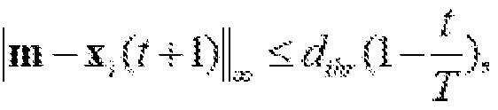 ' (9) where round(x) is the round-off function, x is a position, vector, m is a stored position, Xmemory is the set of the historical positions that have been actually explored, Xi(H- l) is the latest position assigned to the /-th wolf, t is the current iteration number, 11 11¥ represents the oo-norm, T indicates the total iteration number, and CIME is the initial distance threshold determined by the machining error of the available technology. The round-off strategy is based on printing
precision. The distance threshold decreases linearly with the iteration number. This forbids solution aggregation during the exploration while preventing optimum missing in the exploitation course. Analogously, the initialization of the GWO is also modified to avoid seed aggregation.
' (9) where round(x) is the round-off function, x is a position, vector, m is a stored position, Xmemory is the set of the historical positions that have been actually explored, Xi(H- l) is the latest position assigned to the /-th wolf, t is the current iteration number, 11 11¥ represents the oo-norm, T indicates the total iteration number, and CIME is the initial distance threshold determined by the machining error of the available technology. The round-off strategy is based on printing
precision. The distance threshold decreases linearly with the iteration number. This forbids solution aggregation during the exploration while preventing optimum missing in the exploitation course. Analogously, the initialization of the GWO is also modified to avoid seed aggregation.
Through Eq.(9), the searching region is discretized, and repetitive searches are forbidden. The hunting expanse thus diminishes. Meanwhile, individual wolves are not encouraged to search for the prey around a poor position, which eliminates the solutions that are hypertensive to fabrication and simulation errors. To further reduce the hunting expanse, an optimization goal is introduced so that the algorithm may stop in advance. The original GWO is designed to minimize the cost function. The only stop criterion is the total iteration number, implying that the optimization goal is minus infinity.
According to Eq.(9), during the exploration stage, if an excellent solution is just a tiny step away from a poor one, it is not adopted due to lack of robustness. Hence, Eq.(9) also eliminates the solutions that are hypertensive to fabrication and simulation errors. This advantage especially applies to 3D-printed horns and OMTs with multiple structural discontinuities. Besides, each element in the positions vector x is rounded off according to the available manufacture precision from the vendor, which discretizes the solution space for less simulation cost and more robustness.
Besides reducing hunting expanse, another efficient way to cut down the time cost of the GWO-based automated design process is to modify the exploration and exploitation stages simultaneously. It has been proved that when the encircling coefficient a in Eq.(6) is larger than unity, exploration is promoted. In contrast, if a<l, exploitation dominates and all wolves start to attack the prey. Several ways have been put forward to amend this coefficient, including adopting nonlinear functions, introducing multiple tuning parameters, using fuzzy logic, etc. However, it has been pointed out that, generally, the encircling coefficient is not correlated to the fitness of each solution. During one group
hunting, all individuals update their positions according to the alpha, beta, and delta wolves. Insufficient attention is paid to their own findings, especially when the wolf population is large. This strategy minimizes the memory requirement of the GWO, but as mentioned before, this matters little in EM design. A solution updating approach from an adaptive cuckoo search algorithm is directly adopted, whereas the mechanisms of the two algorithms are different. It is also noticed that in the GWO, the encircling coefficient decreases to zero, suggesting that all but one simulation runs in the last iteration are meaningless. Hence, a novel adaptive encircling coefficient is formulated based on the idea of the dynamic adaption as:
 if / = G, then T = G + 1. (10) where a\ t) and x,(t) are the encircling coefficient and position vector, respectively, of the i h wolf in the fth iteration, t and T are the current and total iteration numbers, respectively; r3 is a random value between [0, 1], Ft_best and F t_worst are the best and worst fitness values in the fth iteration, and F(x) is the fitness function. The comparison between the original and modified encircling coefficients are shown in Figure 9. In this way, a new searching task is generated partially based on the finding of each individual. Moreover, it is noticed that according to (6), the encircling coefficient decreases to zero in the last iteration. This suggests that the assigned positions might be identical. Hence, a minor modification is introduced to eliminate repetitive simulation. The comparison between the original and modified encircling coefficients is shown in Figure 2(a). For MGWO, the exploration and exploitation behaviors are adaptively adjusted in a dynamic range. Meanwhile, the macroscopic balance between them is well maintained.
At last, the initialization course of the GWO is modified to improve the exploration behavior by avoiding sample aggregation. Normally, the GWO starts with a set of stochastic variables within the solution space, but their even distribution is not well guaranteed. A filtering process similar to (9) is thus inserted after the initialization through:
 then, x . is re-initialized. , . . ,
(H) where Xmitiai is the initial sample set, | | 112 represents the 2-norm (Euclidean distance), and N itiai is the number of initial samples. This filtering operation is conducted Ndim times, in which Ndim is the dimension of the solution space.
Based on the above approach, an integrated horn antenna that is compatible with metal 3D printing is designed. The design takes a balance between antenna performance and size. No extra procedures, such as assembly, surface processing, alignment, or fixing are needed. Hence, the fabrication time and cost are minimized. Besides, the volume of the antenna is reduced through optimization. The overall height is around 4lo (96 mm), where lo is the wavelength in free space at the center frequency (12.5 GHz) of the lower band. It is light-weighted and more than 30 percent smaller than the compact machining-based horn antenna operating in the same frequency band in the latest publication. Without screws, the mechanical stability of this succinct structure against severe temperature changes and vibration is excellent. These advantages are preferred in portable devices like automotive antennas, and critical systems, such as satellites.
The horn antenna functions as the feed for an offset-fed reflector, as seen in Figure 7. It is equipped on a shared platform seen in Figure 7(b) with the help of a choking fixture and a pad below, as shown in Figure 7(a). The reflector and platform are also implemented through 3D printing. The reflector is densely perforated to reduce the weight of the whole system. The platform stabilizes the antennas and guarantee that the phase center of the feed is at the focus of the reflector. The configuration of the offset-fed reflector antenna is shown in Figure 7(c).
The performance of the antenna is shown in Figure 8. It operates in two separate bands in the Ku band with impressive beam equalization in three vertical
sections, as presented in Figure 8(a)-(c). The radiation performance is steady with respect to frequency. After it is equipped to the reflector platform, good radiation behaviors at the two frequencies are still maintained, as shown in Figure 8(d) and (e). Due to the stable phase center of the horn antenna, the aperture efficiency of the reflector is 72.66% and 75.67% at 12.5 GHz and 14.25 GHz, respectively.
Figure 10(a) illustrates an example optimization method 1000 for designing the corrugated horn antenna or the separate waveguides of the orthomode transducer based on MGWO. Broadly, the method 1000 comprises:
Step 1002: generating initialization population in a pre-defined solution space;
Step 1004: calculating a fitness value of each grey wolf in the initialization population according to Eq.(ll), each grey wolf defining a solution at a position in the solution space; and
Step 1006: repeatedly: selecting a predetermined number of fitness values based on an ordering of fitness values from large to small ("best fitness values"), and identifying and storing as Xa, Xp, and Xaa position of each best fitness value based on the respective grey wolf; updating and storing position for each grey wolf according to Eq.(8), (10) under (9); and updating and storing the fitness value of each grey wolf in each updated position according to the pre-defined fitness function; and Step 1008: outputting Xa when a predetermined maximum number of repetitions is reached.
The MGWO does not introduce extra tuning parameters over the original GWO, which makes it application-friendly in various fields. The flow chart of MGWO is shown in Figure 10. To compare the performance of the MGWO and GWO, three different algorithm configurations are adopted for the same optimization problem, as seen in Table III. The goal of the MGWO is set as -20 so that it can stop in advance. The convergence curves are shown in Figure 12(a)-(d). These
curves are in line with the features of the GWO, i.e., fast convergence appears in the exploitation stage. Then, Optll was selected for further performance comparison. Ten independent runs were conducted through the GWO and MGWO, respectively. Their average performance is presented in Figure 11. This time, the same stop criterion is applied in the two optimizers. It is observed that the MGWO effectively accelerates the design course.
The GWO and its variants have been tested and compared with other optimizers in terms of tens of algorithm benchmarks. The present disclosure focuses on practical EM design problems since the proposed MGWO is application-oriented. A numerical experiment was conducted, in which the optimization problem of the OMT shown in Figure 1(e) is selected. For comparison, the MGWO, GWO, and genetic algorithm (GA) were applied under the same settings. The S parameter alone was used as the cost function to intuitively demonstrate the performance of the optimizers and eliminate the effect of the weighted coefficient, as seen in Table IV. Four different optimizer configurations were adopted, in which the total simulation runs stayed constant as the population and maximum iteration number varied. The GWO and GA are from Ansys HFSS 2019, respectively. Since the GA has abundant parameters, the default setting was adopted. The optimization goal was set as minimization. To save time, the MGWO was allowed to stop in advance when the cost value is below -20.
Table IV


The convergence curves are shown in Figure 12 where a convergence criterion was added during post- processing. The MGWO finds a satisfactory solution after 506.25 simulation runs on average, whereas the GWO requires more than 53 extra runs. Since the population of the three optimizers is identical, the GA fails to converge within the iteration limit. It tends to perform better as the population number increases, which suggests that the dimension of the solution space is too large for the current population. Optimizing the parameters of the GA could improve its performance. Nonetheless, the parameter configurations of GWO and MGWO are much simpler. They enjoy superior applicability to diverse problems [12], which is preferred in practical applications.
To further compare the modified and original GWO, Opt II was selected in the next experiment. Twenty independent tests were conducted. This time, the two optimizers were both allowed to stop in advance to save time. The experiment settings and results are presented in Table V. The MGWO still shows a better converging rate, and consumes less time and simulation resources. The average cost values after each iteration are shown in Figure 13(a). If the optimizer stopped in advance, the cost values in the subsequent iterations were set to - 22.5, the lower bound of the obtained data. It is observed that the MGWO minimizes the cost value more effectively. In Figure 4(b), the average iteration number needed to obtain a certain cost value is calculated through linear interpolation. The MGWO requires fewer iterations when the objective cost value
is below -10. Since one iteration represents 30 simulation runs in Opt II, the MGWO significantly reduces the time cost of the design procedure.
Table V

The proposed antenna structure seen in Figure 14 and the optimization algorithm are verified. Two 3DP-friendly integrated horn antennas, HI and H2, were designed based on the MGWO. Initially, the configuration of a wideband corrugated horn antenna was automatically generated based on Table I and II through the optimizer. Then, two OMTs having different operating bands were devised in the same way. The orthogonal ports of HI operate in different bands for Ku-band satellite communication. The uplink and downlink bands are chosen as the well-known 14/12GHz ones in Asia-Pacific. To further test the flexibility of the optimizer, the second OMT is aimed to cover a wide band.
The configurations of the two integrated horn antennas are presented in Table V and Figure 1. As presented in Figure 14, the two antennas are printed holistically by an EOS M 290 3D printer with aluminum alloy powder through direct metal laser sintering without redundant supports. No assembling process or fixtures are required, either. Consequently, the weight of these antennas is around 200g each. The thickness of the antenna walls is beyond 1.5 mm to ensure structural robustness. Their ports are connected to BJ120 (WR-75/WG- 17) waveguide-coaxial adaptors with standard flanges.
Table VI
ANTENNA CONFIGURATIONS CORRESPONDING TO FIGURE 1

The measured and simulated S parameters show good agreement, as presented in Figure 15. HI operates in 12.25-12.75 GHz and 14-14.5 GHz with Port 1 and Port 2 excited, respectively. As for H2, the overlapped operating band of the two ports is 10.8-14.7 GHz. Since the corrugated horn is shared by the two designs, the radiated patterns of HI are displayed. As presented in Figure 16, fine consistency is observed between the measured and simulated main beams. Beam equalization and stability are attained. However, the measured cross polarization is not reasonable, which is because the maximum transmitted power of the far-field measurement system is not enough for the Ku band.
It will be appreciated that many further modifications and permutations of various aspects of the described embodiments are possible. Accordingly, the
described aspects are intended to embrace all such alterations, modifications, and variations that fall within the spirit and scope of the appended claims.
Throughout this specification and the claims which follow, unless the context requires otherwise, the word "comprise", and variations such as "comprises" and "comprising", will be understood to imply the inclusion of a stated integer or step or group of integers or steps but not the exclusion of any other integer or step or group of integers or steps.
The reference in this specification to any prior publication (or information derived from it), or to any matter which is known, is not, and should not be taken as an acknowledgment or admission or any form of suggestion that that prior publication (or information derived from it) or known matter forms part of the common general knowledge in the field of endeavour to which this specification relates.
Claims
1. A unitary device comprising: a horn antenna disposed about a horn axis and having an engineered inner surface; and an integrated orthomode transducer comprising a waveguide transition and at least two separate waveguides each having an internal surface, the waveguide transition connecting the at least two separate waveguides to the antenna, wherein the orthogonal transducer is adapted to couple at least two orthogonal linear polarized fields from the at least two separate waveguides into the waveguide transition for transmission by the antenna, and/or decouple at least two orthogonal linear polarized fields received by the waveguide transition from the antenna into respective ones of the at least two separate waveguides.
2. The unitary device according to claim 1, wherein the inner surface of the horn antenna is designed according to a broad class of optimisation algorithms.
3. The unitary device according to any one of claims 1 to 2, wherein the internal surface of at least one of the at least two separate waveguides is designed according to a broad class of optimisation algorithms.
4. The unitary device according to any one of claims 1 to 3, wherein the horn antenna has a circular cross-section.
5. The unitary device according to any one of claims 1 to 4, wherein the horn antenna has a square cross-section.
6. The unitary device according to any one of claims 1 to 5, wherein the horn antenna is adapted to support two or more waveguide modes corresponding to the at least two orthogonal linear polarized fields.
7. The unitary device according to any one of claims 1 to 6, wherein the horn antenna operates in 12.25-12.75 GHz and 14-14.5 GHz.
8. The unitary device according to any one of claims 1 to 7, wherein the waveguide transition is a quasi-elliptical waveguide transition connecting a rectangular and a circular waveguide.
9. The unitary device according to any one of claims 1 to 8, wherein the inner surface of the horn antenna comprises a plurality of ridges, each ridge having a horizontal ridge width, being oriented parallel to the horn axis, with the ridge being located at slots along the inner surface of the horn antenna, each slot having a vertical slot height, and a horizontal slot width, being oriented parallel to the horn axis.
10. The unitary device according to any one of claims 1 to 9, wherein the horn antenna has a flare angle being the angle between a line drawn parallel to the horn axis and a line passing through a top surface of adjacent ones of said ridges.
11. The unitary device according to any one of claims 1 to 10 is formed from at least one of a metal material and a plastic material.
12. The unitary device according to any one of claims 1 to 11, wherein the waveguide transition tapers away from the horn antenna.
13. The unitary device according to any one of claims 1 to 12, wherein the at least one of the at least two of the separate waveguides has a rectangular cross- section.
14. The unitary device according to any one of claims 1 to 13, wherein the at least one of the at least two of the separate waveguides has a circular cross- section.
15. The unitary device according to any one of claims 1 to 14, wherein the at least one of the at least two of the separate waveguides has a waveguide axis at a non-zero angle to the horn axis.
16. The unitary device according to any one of claims 1 to 15, wherein a length of the at least one of the at least two of the separate waveguides is formed from a sequence of sections, each section having a length, width and height, and varying from each adjacent said section in the sequence, in at least one of the length, width and height.
17. An antenna assembly, comprising: a unitary device according to any one of claims 1 to 16; a perforated reflector; and a platform for stabilizing the utility device and the perforated reflector, wherein the horn antenna of the unitary device functions as the feed for the perforated reflector, and a phase center of the horn antenna of the unitary device is at a focus of the perforated reflector.
18. A manufacturing method for manufacturing the antenna assembly according to claim 17, comprising manufacturing at least one of the unitary device, the perforated reflector, and the platform using three-dimensional printing technology.
19. A manufacturing method for manufacturing the unitary device according to any one of claims 1 to 16, comprising manufacturing the unitary device in at least two separate blocks.
20. The manufacturing method according to claim 19 further comprises at least one of: manufacturing each part of the at least two separate blocks as one or more of external protrusions, holes and partially holes; and
providing alignment pins and threaded holes on the at least two separate blocks to facilitate assembly.
21. A method of designing the horn antenna or the separate waveguides of the orthomode transducer based on grey wolf optimizer, comprising: generating initialization population in a pre-defined solution space; calculating a fitness value of each grey wolf in the initialization population according to a pre-defined fitness function, each grey wolf defining a solution at a position in the solution space; and repeatedly: selecting a predetermined number of fitness values based on an ordering of fitness values from large to small ("best fitness values"), and identifying and storing as Xa, Xp, and Xaa position of each best fitness value based on the respective grey wolf; updating and storing position for each grey wolf according to one or more pre-defined functions; and updating and storing the fitness value of each grey wolf in each updated position according to the pre-defined fitness function; and outputting Xa when a predetermined maximum number of repetitions is reached.
22. The method of claim 21, wherein, for each repetition of updating a position for each grey wolf, the method further comprises comparing the updated position with each position of a previous repetition, to determine whether or not to update the fitness value with the updated position.
23. The method of claim 21, wherein the fitness function for designing the horn antenna according to any one of 1 to 7 is determined according to:
 in which B, (i = 14) is the positive weighted coefficient indicating the importance of each requirement, u(x) denotes step function, Sn_max(m) is maximum Sn parameter in dB in the m-th band, Bandwidth i2de(i,j) and XPL(i,j) are the 12dB beamwidth in degree and cross-polarization level in dB, respectively, in the 7-th plane at the /- th frequency, dk denotes the horizontal ridge width and the horizontal slot width in mm, and dtotai is size limitation of the horizontal ridge width and the horizontal slot width.
24. The method of claim 21, wherein the fitness function for designing the horn antenna according to any one of 1 to 7 is determined according to:
 in which D denotes a positive weighted coefficient, u(x) denotes step function, Sii max(i) is maximum Sn parameter in dB in the operating band, cn denotes the horizontal interval width for the nth interval.
Applications Claiming Priority (2)
| Application Number | Priority Date | Filing Date | Title |
|---|---|---|---|
| SG10202007125R | 2020-07-24 | ||
| SG10202007125R | 2020-07-24 |
Publications (1)
| Publication Number | Publication Date |
|---|---|
| WO2022019840A1 true WO2022019840A1 (en) | 2022-01-27 |
Family
ID=79729999
Family Applications (1)
| Application Number | Title | Priority Date | Filing Date |
|---|---|---|---|
| PCT/SG2021/050430 Ceased WO2022019840A1 (en) | 2020-07-24 | 2021-07-22 | Unitary horn antenna |
Country Status (1)
| Country | Link |
|---|---|
| WO (1) | WO2022019840A1 (en) |
Cited By (3)
| Publication number | Priority date | Publication date | Assignee | Title |
|---|---|---|---|---|
| US20240235054A1 (en) * | 2023-01-10 | 2024-07-11 | The Johns Hopkins University | Additively manufactured antenna system for near earth and deep space applications |
| WO2025200476A1 (en) * | 2024-03-26 | 2025-10-02 | 国网上海市电力公司 | Multi-objective optimization method for structure parameters of superconducting cable, and device and medium |
| CN120879230A (en) * | 2025-09-25 | 2025-10-31 | 迪泰(浙江)通信技术有限公司 | Adjustable fixing device for satellite antenna auxiliary reflecting surface and operation method |
Citations (1)
| Publication number | Priority date | Publication date | Assignee | Title |
|---|---|---|---|---|
| CN109755750A (en) * | 2019-03-08 | 2019-05-14 | 北京航空航天大学 | A Dual-Polarized Feed Feed for Broadband Ridged Orthogonal Mode Converters |
-
2021
- 2021-07-22 WO PCT/SG2021/050430 patent/WO2022019840A1/en not_active Ceased
Patent Citations (1)
| Publication number | Priority date | Publication date | Assignee | Title |
|---|---|---|---|---|
| CN109755750A (en) * | 2019-03-08 | 2019-05-14 | 北京航空航天大学 | A Dual-Polarized Feed Feed for Broadband Ridged Orthogonal Mode Converters |
Non-Patent Citations (4)
| Title |
|---|
| BHUTANI A. ET AL.: "3D Metal Printed Ku/Ka Band Modified Turnstile Junction Orthomode Transducer", PROCEEDINGS OF THE ASIA-PACIFIC MICROWAVE CONFERENCE 2016, 9 December 2016 (2016-12-09), pages 1 - 4, XP033099078, [retrieved on 20211027], DOI: 10.1109/APMC.2016.7931276 * |
| CARKACI M. EMRE, CARKACI, SECMEN MUSTAFA: "Design and prototype manufacturing of a feed system for Ku‐band satellite communication by using 3D FDM/PLA printing and conductive paint technology", INTERNATIONAL JOURNAL OF RF AND MICROWAVE COMPUTER-AIDED ENGINEERING, WILEY INTERSCIENCE, vol. 30, no. 4, 1 April 2020 (2020-04-01), pages 1, XP055901303, ISSN: 1096-4290, DOI: 10.1002/mmce.22062 * |
| SAEIDI-MANESH H ET AL.: "Design and Fabrication of Orthogonal-Mode Transducer Using 3-D Printing Technology", IEEE ANTENNAS AND WIRELESS PROPAGATION LETTERS, vol. 17, no. 11, 15 June 2018 (2018-06-15), pages 2013 - 2016, XP011694076, [retrieved on 20211027], DOI: 10.1109/LAWP.2018.2847654 * |
| SHEN J ET AL.: "Compact W-Band ''Swan Neck'' Turnstile Junction Orthomode Transducer Implemented by 3-D Printing", IEEE TRANSACTIONS ON MICROWAVE THEORY AND TECHNIQUES, vol. 68, no. 8, 14 May 2020 (2020-05-14), pages 3408 - 3417, XP011802450, [retrieved on 20211027], DOI: 10.1109/TMTT.2020.2992065 * |
Cited By (4)
| Publication number | Priority date | Publication date | Assignee | Title |
|---|---|---|---|---|
| US20240235054A1 (en) * | 2023-01-10 | 2024-07-11 | The Johns Hopkins University | Additively manufactured antenna system for near earth and deep space applications |
| US12586923B2 (en) * | 2023-01-10 | 2026-03-24 | The Johns Hopkins University | Additively manufactured antenna system for near earth and deep space applications |
| WO2025200476A1 (en) * | 2024-03-26 | 2025-10-02 | 国网上海市电力公司 | Multi-objective optimization method for structure parameters of superconducting cable, and device and medium |
| CN120879230A (en) * | 2025-09-25 | 2025-10-31 | 迪泰(浙江)通信技术有限公司 | Adjustable fixing device for satellite antenna auxiliary reflecting surface and operation method |
Similar Documents
| Publication | Publication Date | Title |
|---|---|---|
| Manica et al. | Synthesis of multi-beam sub-arrayed antennas through an excitation matching strategy | |
| CN105789877B (en) | Four wave beam micro-strips transmission array antenna and its design method based on super surface | |
| Chan et al. | Design of high efficiency circular horn feeds for multibeam reflector applications | |
| US20220239012A1 (en) | Enhanced directivity feed and feed array | |
| CA2459387A1 (en) | Systems and methods for providing optimized patch antenna excitation for mutually coupled patches | |
| CN115081325B (en) | Multi-objective optimization method for lens antenna based on particle swarm and genetic hybrid algorithm | |
| US20210320405A1 (en) | Single-polarized antenna | |
| Toyama | Aperiodic array consisting of subarrays for use in small mobile earth stations | |
| CN101291016A (en) | Substrate-integrated waveguide multi-beam antenna based on the principle of parabolic reflector | |
| WO2024160168A1 (en) | Flat lens antenna, beam phase adjustment method, antenna device, and medium | |
| CN116644615A (en) | Design method and device of array antenna | |
| Kildal | A small dipole-fed resonant reflector antenna with high efficiency, low cross polarization, and low sidelobes | |
| WO2020051459A1 (en) | High-performance dual-polarized antenna feed chain | |
| EP3370304A1 (en) | A c-band conformal antenna using microstrip circular patches and methods thereof | |
| CN116315720B (en) | Orbital angular momentum beam-switchable Cassegrain antenna based on array metasurface | |
| Rogers et al. | Wide-band sleeve-cage and sleeve-helical antennas | |
| CN107482311B (en) | Helical Antenna System | |
| Nissanov et al. | Gain and Bandwidth Enhancement Techniques for Terahertz Planar Antenna for 6G Communication | |
| Schejbal et al. | Directivity of planar antennas | |
| Yong et al. | Wideband cavity-backed slot subarray fed by gap ridge waveguide for 5G mmwave base station | |
| Boulaich et al. | Constrained Multi-Objective Genetic Algorithm Variants for Design and Optimization of Tri-Band Microstrip Patch Antenna loaded CSRR for IoT Applications: A Comparative Case Study | |
| Prasannakumar | Wideband bi-static and monostatic STAR antenna systems | |
| Narváez et al. | Landstorfer Antenna Structure Shaping Based on Parameterized Parallel Curves | |
| Meyer et al. | Substrate integrated waveguide pedestal filtering-antenna and-arrays for 5G radio frequency front-ends | |
| Santilián-Haro et al. | Single layer metasurface lens antenna |
Legal Events
| Date | Code | Title | Description |
|---|---|---|---|
| 121 | Ep: the epo has been informed by wipo that ep was designated in this application |
Ref document number: 21845233 Country of ref document: EP Kind code of ref document: A1 |
|
| NENP | Non-entry into the national phase |
Ref country code: DE |
|
| 122 | Ep: pct application non-entry in european phase |
Ref document number: 21845233 Country of ref document: EP Kind code of ref document: A1 |