WO2022019245A1 - Disk brake device - Google Patents
Disk brake device Download PDFInfo
- Publication number
- WO2022019245A1 WO2022019245A1 PCT/JP2021/026884 JP2021026884W WO2022019245A1 WO 2022019245 A1 WO2022019245 A1 WO 2022019245A1 JP 2021026884 W JP2021026884 W JP 2021026884W WO 2022019245 A1 WO2022019245 A1 WO 2022019245A1
- Authority
- WO
- WIPO (PCT)
- Prior art keywords
- piston
- cap
- main body
- brake device
- disc brake
- Prior art date
Links
Images


Classifications
-
- B—PERFORMING OPERATIONS; TRANSPORTING
- B60—VEHICLES IN GENERAL
- B60T—VEHICLE BRAKE CONTROL SYSTEMS OR PARTS THEREOF; BRAKE CONTROL SYSTEMS OR PARTS THEREOF, IN GENERAL; ARRANGEMENT OF BRAKING ELEMENTS ON VEHICLES IN GENERAL; PORTABLE DEVICES FOR PREVENTING UNWANTED MOVEMENT OF VEHICLES; VEHICLE MODIFICATIONS TO FACILITATE COOLING OF BRAKES
- B60T13/00—Transmitting braking action from initiating means to ultimate brake actuator with power assistance or drive; Brake systems incorporating such transmitting means, e.g. air-pressure brake systems
- B60T13/10—Transmitting braking action from initiating means to ultimate brake actuator with power assistance or drive; Brake systems incorporating such transmitting means, e.g. air-pressure brake systems with fluid assistance, drive, or release
- B60T13/58—Combined or convertible systems
- B60T13/588—Combined or convertible systems both fluid and mechanical assistance or drive
-
- B—PERFORMING OPERATIONS; TRANSPORTING
- B60—VEHICLES IN GENERAL
- B60T—VEHICLE BRAKE CONTROL SYSTEMS OR PARTS THEREOF; BRAKE CONTROL SYSTEMS OR PARTS THEREOF, IN GENERAL; ARRANGEMENT OF BRAKING ELEMENTS ON VEHICLES IN GENERAL; PORTABLE DEVICES FOR PREVENTING UNWANTED MOVEMENT OF VEHICLES; VEHICLE MODIFICATIONS TO FACILITATE COOLING OF BRAKES
- B60T1/00—Arrangements of braking elements, i.e. of those parts where braking effect occurs specially for vehicles
- B60T1/02—Arrangements of braking elements, i.e. of those parts where braking effect occurs specially for vehicles acting by retarding wheels
- B60T1/06—Arrangements of braking elements, i.e. of those parts where braking effect occurs specially for vehicles acting by retarding wheels acting otherwise than on tread, e.g. employing rim, drum, disc, or transmission or on double wheels
- B60T1/065—Arrangements of braking elements, i.e. of those parts where braking effect occurs specially for vehicles acting by retarding wheels acting otherwise than on tread, e.g. employing rim, drum, disc, or transmission or on double wheels employing disc
-
- B—PERFORMING OPERATIONS; TRANSPORTING
- B60—VEHICLES IN GENERAL
- B60T—VEHICLE BRAKE CONTROL SYSTEMS OR PARTS THEREOF; BRAKE CONTROL SYSTEMS OR PARTS THEREOF, IN GENERAL; ARRANGEMENT OF BRAKING ELEMENTS ON VEHICLES IN GENERAL; PORTABLE DEVICES FOR PREVENTING UNWANTED MOVEMENT OF VEHICLES; VEHICLE MODIFICATIONS TO FACILITATE COOLING OF BRAKES
- B60T13/00—Transmitting braking action from initiating means to ultimate brake actuator with power assistance or drive; Brake systems incorporating such transmitting means, e.g. air-pressure brake systems
- B60T13/74—Transmitting braking action from initiating means to ultimate brake actuator with power assistance or drive; Brake systems incorporating such transmitting means, e.g. air-pressure brake systems with electrical assistance or drive
- B60T13/741—Transmitting braking action from initiating means to ultimate brake actuator with power assistance or drive; Brake systems incorporating such transmitting means, e.g. air-pressure brake systems with electrical assistance or drive acting on an ultimate actuator
-
- B—PERFORMING OPERATIONS; TRANSPORTING
- B60—VEHICLES IN GENERAL
- B60T—VEHICLE BRAKE CONTROL SYSTEMS OR PARTS THEREOF; BRAKE CONTROL SYSTEMS OR PARTS THEREOF, IN GENERAL; ARRANGEMENT OF BRAKING ELEMENTS ON VEHICLES IN GENERAL; PORTABLE DEVICES FOR PREVENTING UNWANTED MOVEMENT OF VEHICLES; VEHICLE MODIFICATIONS TO FACILITATE COOLING OF BRAKES
- B60T13/00—Transmitting braking action from initiating means to ultimate brake actuator with power assistance or drive; Brake systems incorporating such transmitting means, e.g. air-pressure brake systems
- B60T13/74—Transmitting braking action from initiating means to ultimate brake actuator with power assistance or drive; Brake systems incorporating such transmitting means, e.g. air-pressure brake systems with electrical assistance or drive
- B60T13/746—Transmitting braking action from initiating means to ultimate brake actuator with power assistance or drive; Brake systems incorporating such transmitting means, e.g. air-pressure brake systems with electrical assistance or drive and mechanical transmission of the braking action
-
- F—MECHANICAL ENGINEERING; LIGHTING; HEATING; WEAPONS; BLASTING
- F16—ENGINEERING ELEMENTS AND UNITS; GENERAL MEASURES FOR PRODUCING AND MAINTAINING EFFECTIVE FUNCTIONING OF MACHINES OR INSTALLATIONS; THERMAL INSULATION IN GENERAL
- F16D—COUPLINGS FOR TRANSMITTING ROTATION; CLUTCHES; BRAKES
- F16D55/00—Brakes with substantially-radial braking surfaces pressed together in axial direction, e.g. disc brakes
- F16D55/02—Brakes with substantially-radial braking surfaces pressed together in axial direction, e.g. disc brakes with axially-movable discs or pads pressed against axially-located rotating members
- F16D55/22—Brakes with substantially-radial braking surfaces pressed together in axial direction, e.g. disc brakes with axially-movable discs or pads pressed against axially-located rotating members by clamping an axially-located rotating disc between movable braking members, e.g. movable brake discs or brake pads
- F16D55/224—Brakes with substantially-radial braking surfaces pressed together in axial direction, e.g. disc brakes with axially-movable discs or pads pressed against axially-located rotating members by clamping an axially-located rotating disc between movable braking members, e.g. movable brake discs or brake pads with a common actuating member for the braking members
- F16D55/225—Brakes with substantially-radial braking surfaces pressed together in axial direction, e.g. disc brakes with axially-movable discs or pads pressed against axially-located rotating members by clamping an axially-located rotating disc between movable braking members, e.g. movable brake discs or brake pads with a common actuating member for the braking members the braking members being brake pads
- F16D55/226—Brakes with substantially-radial braking surfaces pressed together in axial direction, e.g. disc brakes with axially-movable discs or pads pressed against axially-located rotating members by clamping an axially-located rotating disc between movable braking members, e.g. movable brake discs or brake pads with a common actuating member for the braking members the braking members being brake pads in which the common actuating member is moved axially, e.g. floating caliper disc brakes
-
- F—MECHANICAL ENGINEERING; LIGHTING; HEATING; WEAPONS; BLASTING
- F16—ENGINEERING ELEMENTS AND UNITS; GENERAL MEASURES FOR PRODUCING AND MAINTAINING EFFECTIVE FUNCTIONING OF MACHINES OR INSTALLATIONS; THERMAL INSULATION IN GENERAL
- F16D—COUPLINGS FOR TRANSMITTING ROTATION; CLUTCHES; BRAKES
- F16D55/00—Brakes with substantially-radial braking surfaces pressed together in axial direction, e.g. disc brakes
- F16D55/02—Brakes with substantially-radial braking surfaces pressed together in axial direction, e.g. disc brakes with axially-movable discs or pads pressed against axially-located rotating members
- F16D55/22—Brakes with substantially-radial braking surfaces pressed together in axial direction, e.g. disc brakes with axially-movable discs or pads pressed against axially-located rotating members by clamping an axially-located rotating disc between movable braking members, e.g. movable brake discs or brake pads
- F16D55/228—Brakes with substantially-radial braking surfaces pressed together in axial direction, e.g. disc brakes with axially-movable discs or pads pressed against axially-located rotating members by clamping an axially-located rotating disc between movable braking members, e.g. movable brake discs or brake pads with a separate actuating member for each side
-
- F—MECHANICAL ENGINEERING; LIGHTING; HEATING; WEAPONS; BLASTING
- F16—ENGINEERING ELEMENTS AND UNITS; GENERAL MEASURES FOR PRODUCING AND MAINTAINING EFFECTIVE FUNCTIONING OF MACHINES OR INSTALLATIONS; THERMAL INSULATION IN GENERAL
- F16D—COUPLINGS FOR TRANSMITTING ROTATION; CLUTCHES; BRAKES
- F16D65/00—Parts or details
- F16D65/14—Actuating mechanisms for brakes; Means for initiating operation at a predetermined position
- F16D65/16—Actuating mechanisms for brakes; Means for initiating operation at a predetermined position arranged in or on the brake
- F16D65/18—Actuating mechanisms for brakes; Means for initiating operation at a predetermined position arranged in or on the brake adapted for drawing members together, e.g. for disc brakes
- F16D65/183—Actuating mechanisms for brakes; Means for initiating operation at a predetermined position arranged in or on the brake adapted for drawing members together, e.g. for disc brakes with force-transmitting members arranged side by side acting on a spot type force-applying member
-
- F—MECHANICAL ENGINEERING; LIGHTING; HEATING; WEAPONS; BLASTING
- F16—ENGINEERING ELEMENTS AND UNITS; GENERAL MEASURES FOR PRODUCING AND MAINTAINING EFFECTIVE FUNCTIONING OF MACHINES OR INSTALLATIONS; THERMAL INSULATION IN GENERAL
- F16D—COUPLINGS FOR TRANSMITTING ROTATION; CLUTCHES; BRAKES
- F16D65/00—Parts or details
- F16D65/78—Features relating to cooling
- F16D2065/785—Heat insulation or reflection
-
- F—MECHANICAL ENGINEERING; LIGHTING; HEATING; WEAPONS; BLASTING
- F16—ENGINEERING ELEMENTS AND UNITS; GENERAL MEASURES FOR PRODUCING AND MAINTAINING EFFECTIVE FUNCTIONING OF MACHINES OR INSTALLATIONS; THERMAL INSULATION IN GENERAL
- F16D—COUPLINGS FOR TRANSMITTING ROTATION; CLUTCHES; BRAKES
- F16D2121/00—Type of actuator operation force
- F16D2121/02—Fluid pressure
- F16D2121/04—Fluid pressure acting on a piston-type actuator, e.g. for liquid pressure
-
- F—MECHANICAL ENGINEERING; LIGHTING; HEATING; WEAPONS; BLASTING
- F16—ENGINEERING ELEMENTS AND UNITS; GENERAL MEASURES FOR PRODUCING AND MAINTAINING EFFECTIVE FUNCTIONING OF MACHINES OR INSTALLATIONS; THERMAL INSULATION IN GENERAL
- F16D—COUPLINGS FOR TRANSMITTING ROTATION; CLUTCHES; BRAKES
- F16D2121/00—Type of actuator operation force
- F16D2121/18—Electric or magnetic
- F16D2121/24—Electric or magnetic using motors
-
- F—MECHANICAL ENGINEERING; LIGHTING; HEATING; WEAPONS; BLASTING
- F16—ENGINEERING ELEMENTS AND UNITS; GENERAL MEASURES FOR PRODUCING AND MAINTAINING EFFECTIVE FUNCTIONING OF MACHINES OR INSTALLATIONS; THERMAL INSULATION IN GENERAL
- F16D—COUPLINGS FOR TRANSMITTING ROTATION; CLUTCHES; BRAKES
- F16D2125/00—Components of actuators
- F16D2125/02—Fluid-pressure mechanisms
- F16D2125/06—Pistons
-
- F—MECHANICAL ENGINEERING; LIGHTING; HEATING; WEAPONS; BLASTING
- F16—ENGINEERING ELEMENTS AND UNITS; GENERAL MEASURES FOR PRODUCING AND MAINTAINING EFFECTIVE FUNCTIONING OF MACHINES OR INSTALLATIONS; THERMAL INSULATION IN GENERAL
- F16D—COUPLINGS FOR TRANSMITTING ROTATION; CLUTCHES; BRAKES
- F16D2125/00—Components of actuators
- F16D2125/18—Mechanical mechanisms
- F16D2125/20—Mechanical mechanisms converting rotation to linear movement or vice versa
- F16D2125/34—Mechanical mechanisms converting rotation to linear movement or vice versa acting in the direction of the axis of rotation
- F16D2125/40—Screw-and-nut
Definitions
- the present invention relates to a disc brake device.
- Disc brake devices are increasingly used not only for the front wheels of automobiles but also for the rear wheels because they have excellent heat dissipation and can finely adjust the braking force during driving.
- Disc brake devices are divided into hydraulic disc brake devices that use hydraulic fluid to obtain braking force and electric disc brake devices that use electrically driveable actuators to obtain braking force. Can be separated.
- a braking force by a service brake is generated by sending brake oil (fluid) into a cylinder to generate a parking brake.
- An electric parking brake type structure is known in which the braking force generated by the brake fluid is generated by using an electric actuator such as a rotation linear motion conversion mechanism.
- brake oil is stored in the cylinder, so when the pad is pressed against the rotating rotor and becomes hot, heat is transferred to the brake oil via the piston, and the brake is applied. There is a problem that the temperature of the oil tends to rise. When the temperature of the brake oil rises, it causes deterioration of the brake oil and causes a vapor lock phenomenon.
- the piston has a split structure as disclosed in Japanese Patent Application Laid-Open No. 2015-25550. Specifically, it is conceivable that the piston is composed of a piston body that is fitted in the cylinder and receives hydraulic pressure, and a piston cap that presses the pad. According to such a configuration, the amount of heat transferred to the brake oil can be reduced as compared with the case where the piston is integrated. Therefore, it is possible to suppress the temperature rise of the brake oil.
- a rotary linear motion conversion mechanism consisting of a spindle which is a rotary member and a nut which is a linear motion member
- the spindle is rotated in the forward rotation direction in order to obtain braking force by the parking brake.
- slippage occurs between the piston body and the piston cap on which torque acts from the nut, and the piston body may slip together with the nut. Therefore, it becomes difficult to stably obtain the braking force of the parking brake.
- the nut moves (full release) to the limit position on the anti-rotor side, and the nut and spindle are locked. (That is, the nut cannot be moved in the axial direction due to the rotation of the spindle, and the nut is forcibly rotated together with the spindle.)
- the electric motor that is the drive source may reach the stall torque (maximum current).
- the present invention has been made to solve the above problems, and it is possible to stably obtain the braking force by the parking brake while having a structure in which the temperature rise of the brake oil can be suppressed, and the linear motion member. It is an object of the present invention to provide an electric parking brake type disc brake device that can solve the problem that occurs when the brake fluid is fully released to the anti-rotor side.
- the disc brake device of the present invention includes a pad, a caliper, a piston, and a rotational linear motion conversion mechanism.
- the caliper has a cylinder with the pad side open.
- the piston is fitted in the cylinder and presses the pad toward the rotor.
- the rotary linear motion conversion mechanism converts the rotary motion of the drive source into a linear motion, thereby pushing the piston toward the rotor.
- the braking force by the service brake is generated by feeding the brake oil into the cylinder, and the braking force by the parking brake is generated by operating the rotation linear motion conversion mechanism.
- the piston is composed of a piston body and a piston cap, which are divided into two in the axial direction.
- the rotary linear motion conversion mechanism is screwed to the rotary member and the rotary member driven to be rotationally driven by the drive source, and is arranged inside the piston body so as to be unable to engage with the piston body in relative rotation. It also has a linear motion member that presses the piston body in the axial direction. Between the piston body and the piston cap, when the rotating member is rotationally driven in the forward rotation direction in order to move the linear motion member to the rotor side, the forward rotation direction of the piston body with respect to the piston cap. When the rotating member is rotationally driven in the reverse rotation direction in order to regulate the relative rotation to the piston cap and move the linear motion member to the anti-rotor side, the piston body is relative to the piston cap in the reverse rotation direction. It has a one-way rotation control unit that allows rotation.
- the one-way rotation restricting portion is provided with at least one (preferably a plurality) convex or concave main body side engaging portions provided on the piston main body, and the piston.
- the main body side engaging portion may be integrally formed with other parts constituting the piston main body, or may be formed separately from the other parts and fixed to the other parts.
- the cap-side engaging portion may be integrally formed with other parts constituting the piston cap, or may be formed separately from the other parts and fixed to the other parts.
- the piston body may be made of metal
- the piston cap may be made of metal or synthetic resin.
- at least one of the portions that come into contact with the main body side engaging portion when the rotating member is rotationally driven in the forward rotation direction is regulated to be parallel (including substantially parallel) to the central axis of the piston. It can have a surface.
- the main body side engaging portion is moved backward in the reverse rotation direction to a portion that comes into contact with the cap side engaging portion when the rotating member is rotationally driven in the reverse rotation direction. It is possible to have a main body side guide surface that approaches the rotor in the axial direction toward the side, and when the rotating member is rotationally driven in the reverse rotation direction, the main body side guide surface is provided by the cap side engaging portion. Can be pushed up.
- the main body side guide surface may be an inclined surface or a curved surface (including a partial cylindrical surface having an arc-shaped cross section and a partial spherical surface).
- the cap-side engaging portion is brought into contact with the main body-side engaging portion when the rotating member is rotationally driven in the reverse rotation direction, and is forward in the reverse rotation direction. It is possible to have a cap-side guide surface that moves away from the rotor in the axial direction toward the side, and when the rotating member is rotationally driven in the reverse rotation direction, the cap-side guide surface causes the main body-side engaging portion. Can be pushed up.
- the cap-side guide surface may be an inclined surface or a curved surface (including a partial cylindrical surface and a partial spherical surface having an arc-shaped cross section).
- the cap-side engaging portion of the piston cap can be made of metal.
- the piston cap is provided with a cap body made of synthetic resin and a metal engaging piece molded in the cap body, and a part of the engaging piece is used to make the cap.
- a side engaging portion can be configured.
- the piston cap is further provided with a cap body made of synthetic resin, a metal engaging piece partially (base) molded in the cap body, and a metal power transmission member. Can be. Then, the power transmission member is exposed from the end surface of the cap body, and the exposed surface can form a cap-side transmission surface described later.
- a plurality of the main body side engaging portions may be provided separated in the circumferential direction, and a plurality of the cap side engaging portions may be provided separated in the circumferential direction. ..
- the plurality of main body-side engaging portions can be arranged at equal intervals in the circumferential direction, and the plurality of cap-side engaging portions can be arranged at equal intervals in the circumferential direction.
- the piston cap can support the relative displacement in the axial direction with respect to the piston body.
- the piston cap when the rotating member is rotationally driven in the reverse rotation direction, the piston cap is shafted with respect to the piston body by at least the amount that the main body side engaging portion can overcome the cap side engaging portion. Relative displacement with respect to direction can be supported as possible.
- an axial force transmitting portion for transmitting an axial force between the piston main body and the piston cap can be further provided between the piston main body and the piston cap.
- the axial force transmitting unit can be provided separately from the one-way rotation restricting unit.
- the axial force transmitting portion is transferred to the flat surface-shaped transmission surface on the main body side and the piston cap, which are located on a virtual plane orthogonal to the central axis of the piston main body. It can be composed of a flat surface-shaped transmission surface on the cap side, which is located on a virtual plane orthogonal to the central axis of the piston cap.
- the one-way rotation restricting unit can have a function of transmitting an axial force between the piston body and the piston cap.
- the one-way rotation restricting portion is provided on the main body side sliding contact surface provided on the piston main body and the cap side sliding contact surface provided on the piston cap and facing the main body side sliding contact surface in the axial direction. It can be composed of faces. At least one of the main body side sliding contact surface and the cap side sliding contact surface is surface-treated to increase the friction coefficient between the main body side sliding contact surface and the cap side sliding contact surface, or It can be composed of friction members.
- the rotating member When the rotating member is rotationally driven in the forward rotation direction, the axial force acting on the cap-side sliding contact surface from the main body-side sliding contact surface increases, and the main body-side sliding contact surface and the cap-side sliding contact surface increase.
- the rotating member When the rotating member is rotationally driven in the reverse rotation direction by frictionally engaging with the surface so as not to rotate relative to each other, the axial force acting from the main body side sliding contact surface to the cap side sliding contact surface decreases.
- the main body side sliding contact surface can be rotated relative to the cap side sliding contact surface in the reverse rotation direction.
- the structure is such that the temperature rise of the brake oil can be suppressed, the braking force due to the parking brake can be stably obtained, and the problem that occurs when the linear motion member is fully released to the anti-rotor side. It is possible to realize an electric parking brake type disc brake device that can eliminate the problem.
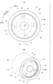
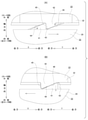
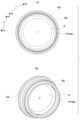
- FIG. 1 is a front view showing a disc brake device of the first example of the embodiment.
- FIG. 2 is a plan view showing the disc brake device of the first example of the embodiment.
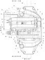
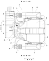
- FIG. 3 is a cross-sectional view taken along the line AA of FIG.
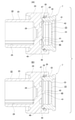
- FIG. 4 is a partially enlarged view of FIG.
- FIG. 5 is a schematic cross-sectional view showing an example of a detent structure of the piston cap with respect to the inner pad with respect to the first example of the embodiment.
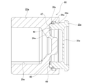
- 6A and 6B are cross-sectional views showing a combined piston taken out with respect to the first example of the embodiment, FIG. 6A shows a case where the spindle is rotationally driven in the forward rotation direction, and FIG. 9A shows a case where the spindle is rotationally driven in the forward rotation direction.
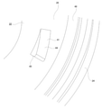
- FIG. 7A and 7B are views showing the piston main body taken out with respect to the first example of the embodiment, FIG. 7A is a front view, and FIG. 7B is a perspective view.
- FIG. 8 is a partially enlarged view of FIG. 7B.
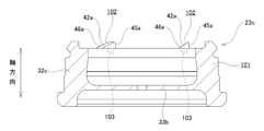
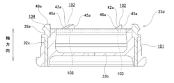
- 9A and 9B are views showing the piston cap taken out with respect to the first example of the embodiment, FIG. 9A is a rear view, and FIG. 9B is a perspective view.
- FIG. 10 is a partially enlarged view of FIG. 9B.
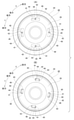
- FIG. 11 is a front view of the piston body shown for explaining the function of the one-way rotation restricting unit with respect to the first example of the embodiment, and FIG.
- FIG. 11A is a rotational drive of the spindle in the forward rotation direction.
- the positional relationship between the main body side engaging portion and the cap side engaging portion is shown
- FIG. 11B shows the main body side engaging portion and the cap side when the spindle is rotationally driven in the reverse rotation direction.
- the positional relationship with the engaging portion is shown.
- 12A is a partially enlarged view of FIG. 6A
- FIG. 12B is a partially enlarged view of FIG. 6B.
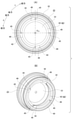
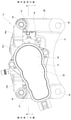
- FIG. 13 is a plan view showing the disc brake device of the second example of the embodiment.
- FIG. 14 is a rear view showing the disc brake device of the second example of the embodiment.
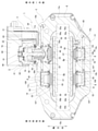
- FIG. 15 is a cross-sectional view taken along the line BB of FIG. FIG.
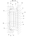
- FIG. 16 is a cross-sectional view showing the piston taken out with respect to the second example of the embodiment.
- FIG. 17 is a diagram corresponding to FIG. 7, showing a third example of the embodiment.
- FIG. 18 is a diagram corresponding to FIG. 9, showing a third example of the embodiment.
- FIG. 19 is a schematic cross-sectional view of a piston cap showing a fourth example of the embodiment.
- FIG. 20 is a schematic cross-sectional view of a piston cap showing a fifth example of the embodiment.
- FIG. 21 is a schematic diagram corresponding to FIG. 12, showing a sixth example of the embodiment.
- FIG. 22 is a schematic diagram corresponding to FIG. 12, showing a seventh example of the embodiment.
- the disc brake device 1 of this example is an electric parking brake type disc brake device, and has both a function as a hydraulic service brake and a function as an electric parking brake.
- the disc brake device 1 has a configuration in which a hydraulic opposed piston type brake mechanism unit 2 that functions as a service brake is combined with an electric floating type brake mechanism unit 3 that functions as a parking brake.
- the disc brake device 1 includes an opposed piston type caliper 4 fixed to a suspension device such as a knuckle, a clamp member 5 supported to enable axial displacement with respect to the caliper 4, and a pair of pads 6a and 6b ( The outer pad 6a and the inner pad 6b) and a total of four pistons 7 and 8 (one combined piston 7 and three service-dedicated pistons 8) are provided.
- the axial direction, the circumferential direction, and the radial direction refer to the axial direction, the circumferential direction, and the radial direction of the disk-shaped rotor 9 (see FIG. 2) that rotates together with the wheels, unless otherwise specified.
- the front and back directions of FIGS. 1 and 7 (A) and 9 (A), the vertical direction of FIGS. 2 and 3, and the horizontal direction of FIGS. 4 to 6 correspond to the axial directions, respectively.
- the center side of the vehicle body when assembled to the vehicle body is called the inside in the axial direction, and the outside of the vehicle body when assembled to the vehicle body is called the outside in the axial direction.
- FIGS. 1 to 3 and the upper side of FIG. 4 correspond to the circumferential direction, respectively.
- the right side of FIGS. 1 to 3 and the upper side of FIG. 4 are referred to as one side in the circumferential direction
- the left side of FIGS. 1 to 3 and the lower side of FIG. 4 are referred to as the other side in the circumferential direction.
- one side in the circumferential direction is the turning side when the vehicle is moving forward and the turning side when the vehicle is moving backward
- the other side in the circumferential direction is the turning side when the vehicle is moving forward and the turning side when the vehicle is moving backward.
- the vertical direction of FIG. 1 and the front and back directions of FIGS. 2 and 3 correspond to the radial direction, respectively.
- FIGS. 2 and 3 are radially outer, and the lower side of FIG. 1 and the back side of FIGS. 2 and 3 are radially inner, respectively.
- the entry side is the side where the rotor 9 enters the caliper 4, and the exit side is the side where the rotor 9 exits from the caliper 4.
- the disc brake device 1 applies the braking force of the service brake to all (four in the illustrated example) cylinders 10a, 10b, 11a, 11b provided in the caliper 4 constituting the opposed piston type brake mechanism unit 2. Obtained by feeding brake oil (pressure oil), which is oil. On the other hand, the disc brake device 1 drives the electric actuator 12 constituting the floating type brake mechanism portion 3 without using the hydraulic oil by the braking force of the parking brake, and the clamp member 5 is applied to the caliper 4. Obtained by relative displacement in the axial direction.
- the opposed piston type brake mechanism unit 2 and the floating type brake mechanism unit 3 commonly use a pair of pads 6a and 6b and one combined piston 7.
- the caliper 4 constituting the opposed piston type brake mechanism 2 supports the outer pad 6a and the inner pad 6b so as to be movable in the axial direction (front and back directions in FIG. 1, vertical direction in FIGS. 2 and 3).
- a caliper 4 is a cast product (including a die-cast molded product) of a light alloy such as an aluminum alloy, and has an outer body portion 13 and an inner body portion 14 arranged on both sides in the axial direction of the rotor 9 and a rotor 9. It has connecting portions 15a, 15b, 16 arranged on the outer side in the radial direction.
- the caliper 4 is supported and fixed to the suspension device by a pair of mounting seats 17 included in the inner body portion 14.
- the entry side connecting portion 15a is arranged on one side in the circumferential direction of the caliper 4 (on the right side of FIGS. 1 to 3 on the entry side when the vehicle is moving forward) and on the radial outside of the rotor 9, and is an outer body portion.
- One side portion in the circumferential direction of 13 and one side portion in the circumferential direction of the inner body portion 14 are connected in the axial direction.
- the turn-out side connecting portion 15b is arranged on the other side in the circumferential direction of the caliper 4 (on the left side in FIGS. 1 to 3 and on the turn-out side when the vehicle is moving forward) and on the radial outside of the rotor 9, and is an outer body portion.
- the other side portion in the circumferential direction of 13 and the other side portion in the circumferential direction of the inner body portion 14 are connected in the axial direction.
- the intermediate connecting portion 16 is arranged in the circumferential intermediate portion of the caliper 4 and radially outside the rotor 9, and axially connects the circumferential intermediate portion of the outer body portion 13 and the circumferential intermediate portion of the inner body portion 14. It is connected to.
- the outer body portion 13 is arranged on the outer side in the axial direction of the rotor 9, and has a turn-in side outer cylinder 10a on one side in the circumferential direction and a turn-out side outer cylinder 10b on the other side in the circumferential direction.
- the inner body portion 14 is arranged inside the rotor 9 in the axial direction, and has a turn-in side inner cylinder 11a on one side in the circumferential direction and a turn-out side inner cylinder 11b on the other side in the circumferential direction.
- the turn-in side outer cylinder 10a and the turn-in side inner cylinder 11a are arranged coaxially so as to face each other in the axial direction, and the turn-out side outer cylinder 10b and the turn-in side inner cylinder 11b are arranged in the axial direction. They are arranged coaxially so as to face each other.
- Each of the outer body portion 13 and the inner body portion 14 is provided with oil passages 18a and 18b inside.
- the oil passage 18a provided inside the outer body portion 13 extends in the circumferential direction, and communicates the turn-in side outer cylinder 10a and the turn-out side outer cylinder 10b with each other.
- the oil passage 18b provided inside the inner body portion 14 extends in the circumferential direction, and communicates the entry-side inner cylinder 11a and the exit-side inner cylinder 11b with each other.
- the two oil passages 18a and 18b communicate with each other.
- the combined piston 7 used for both the service brake and the parking brake is fitted inside the inner cylinder 11a on the entry side so that it can be displaced in the axial direction. I'm dressed up.
- a service-dedicated piston 8 used only for the service brake is fitted inside the remaining three cylinders 10a, 10b, and 11b other than the turn-in side inner cylinder 11a so as to be displaced in the axial direction.
- the entry-side inner cylinder 11a corresponds to the cylinder described in the claims, and as shown in FIGS. 3 and 4, not only is the inner body portion 14 open to the outer surface in the axial direction, but also the inner body is formed. It is also open on the inner side surface of the portion 14 in the axial direction. That is, the turn-in side inner cylinder 11a is formed so as to penetrate the inner body portion 14 in the axial direction.
- the entry-side inner cylinder 11a is a stepped hole, and has a large-diameter hole portion 19 in the outer half portion in the axial direction and a small-diameter hole portion 20 in the inner half portion in the axial direction.
- a guide cylinder 21 is provided at the opening edge of the small diameter hole portion 20.
- the guide cylinder 21 extends inward in the axial direction from the opening edge portion of the small-diameter hole portion 20 of the entry-side inner cylinder 11a, and is arranged coaxially with the entry-side inner cylinder 11a.
- the guide cylinder 21 has a cylindrical shape and has the same inner diameter as the small diameter hole portion 20.
- the length dimension of the guide cylinder 21 in the axial direction is larger than the displacement amount of the clamp member 5 that is displaced in the axial direction when the parking brake is operated.
- the combined piston 7 fitted to the entry-side inner cylinder 11a corresponds to the piston described in the claims and has a split structure divided into two in the axial direction.
- the combined piston 7 is composed of a piston body 22 and a piston cap 23.
- the piston body 22 is made of carbon steel such as S10C or S45C, has a bottomed cylindrical shape, and is fitted to the inner cylinder 11a on the entry side.
- the piston body 22 is arranged on the outer side in the axial direction and fitted in the large diameter hole portion 19, and the small diameter cylinder portion 24 is arranged on the inner side in the axial direction and fitted in the small diameter hole portion 20. It has 25 and.
- the large-diameter tubular portion 24 has a substantially disk-shaped partition wall portion 26.
- the partition wall portion 26 is arranged in an axially intermediate portion of the large-diameter tubular portion 24, and partitions (closes) the inside of the large-diameter tubular portion 24 in the axial direction.
- the axially inner end surface of the large-diameter cylinder portion 24 and the radial outer portion of the axially inner side surface of the partition wall portion 26 are the large-diameter hole portions 19 of the entry-side inner cylinder 11a. Facing the bottom surface 27 in the axial direction.
- the small-diameter tubular portion 25 extends inward in the axial direction from the radial intermediate portion of the inner side surface in the axial direction of the partition wall portion 26, and is arranged coaxially with the large-diameter tubular portion 24.
- a female spline 29 is provided on the inner peripheral surface of the small-diameter tubular portion 25.
- the portion between the large-diameter cylinder portion 24 and the large-diameter hole portion 19 and the portion between the small-diameter cylinder portion 25 and the small-diameter hole portion 20 are sealed by annular piston seals 30a and 30b, respectively.
- the piston seal 30a is mounted in a seal groove 31a formed on the inner peripheral surface of the axially intermediate portion of the large-diameter hole portion 19.
- the piston seal 30b is mounted in a seal groove 31b formed on the inner peripheral surface of the axially intermediate portion of the small diameter hole portion 20.
- the piston cap 23 is made of, for example, stainless steel, titanium, or synthetic resin, and is composed of a tubular portion 32 and a closing plate portion 33, and is formed in a bottomed cylindrical shape.
- the axial inner portion of the tubular portion 32 is arranged inside the large-diameter tubular portion 24, and the axial outer portion of the tubular portion 32 is prevented from rotating with respect to the inner pad 6b.
- the piston cap 23 is provided on the inner pad 6b (back plate 58) with respect to the engaging recess 34 provided on the axially outer end surface of the tubular portion 32.
- the detent structure between the piston cap and the inner pad is omitted, and the frictional force acting between the piston cap and the inner pad is used to make the piston cap with respect to the inner pad. It is also possible to regulate the relative rotation of.
- a piston boot 36 is hung between the tubular portion 32 of the piston cap 23 and the opening edge portion on the outer side in the axial direction of the large-diameter hole portion 19 of the inner cylinder 11a on the entry side.
- the radial outer portion of the piston boot 36 is mounted in an annular recess 37 provided in the axially outer opening edge of the large diameter hole portion 19, and the radial inner portion of the piston boot 36 is a tubular portion. It is fitted outside in the axial middle portion of 32.
- a piston ring 38 having a C-shape as a whole is externally fitted to a portion of the cylindrical portion 32 of the piston cap 23 that is arranged inside the large-diameter tubular portion 24 of the piston body 22.
- the piston ring 38 has a circular cross-sectional shape.
- the radial outer portion of the piston ring 38 is engaged with the holding groove 39 having a substantially rectangular cross section provided on the inner peripheral surface of the large-diameter tubular portion 24 so as to be displaced in the axial direction.
- the piston cap 23 is capable of holding a relative displacement in the axial direction with respect to the piston main body 22.
- the piston ring When carrying out the present invention, the piston ring is fitted inwardly on the inner peripheral surface of the large-diameter cylinder portion, and the radial inner portion of the piston ring is axially relative to the holding concave groove formed on the outer peripheral surface of the piston cap. It is also possible to engage the displacement with respect to.
- the central axis O 23 of the piston cap 23 With the piston cap 23 held against the piston body 22, the central axis O 23 of the piston cap 23 (see FIG. 9) and the central axis O 22 of the piston body 22 (see FIG. 7) are arranged coaxially with each other. Will be done.
- the central axis of the piston cap 23 and the central axis of the piston body 22 arranged coaxially with each other are also referred to as the central axis of the combined piston 7.
- the one-way rotation restricting portion 40 is arranged between the piston main body 22 and the piston cap 23. Then, unlike the conventional structure described above, the piston body 22 and the piston cap 23 are not connected by being fitted in an uneven manner or are not connected in a relative non-rotatable manner in any direction. It is connected via 40.
- the one-way rotation restricting unit 40 has a function like a one-way clutch, and the relative rotation of the piston body 22 with respect to the piston cap 23 in the forward rotation direction (arrow X direction in FIGS. 7, 11 and 12). Is restricted (blocked), but relative rotation in the reverse rotation direction (arrow Y direction in FIGS. 7, 11 and 12) is allowed. That is, as will be described later, when the one-way rotation regulating unit 40 rotationally drives the spindle 82 of the rotational linear motion conversion mechanism 79 constituting the electric actuator 12 in the forward rotation direction in order to obtain the braking force by the parking brake. (At the time of application), the relative rotation of the piston body 22 with respect to the piston cap 23 in the forward rotation direction is restricted.
- the one-way rotation regulating unit 40 rotationally drives the spindle 82 in the reverse rotation direction (at the time of release) in order to release the braking force due to the parking brake
- the piston body 22 rotates in the reverse direction with respect to the piston cap 23. Allows relative rotation in the direction.
- the one-way rotation restricting unit 40 includes a main body side engaging portion 41 on the piston main body 22 and a cap side engaging portion 42 on the piston cap 23.
- the main body side engaging portion 41 and the cap side engaging portion 42 are mechanically (non-dissociably) engaged when the spindle 82 is rotationally driven in the forward rotation direction.
- the main body side engaging portion 41 is provided on the axially outer surface of the partition wall portion 26 of the piston main body 22. As shown in FIGS. 7 and 8, the main body side engaging portion 41 has a convex shape protruding in the axial direction, and has a circumferential direction on the radial outer portion of the axial outer surface of the partition wall portion 26. A plurality of (four in the illustrated example) are provided at equal intervals. The plurality of main body side engaging portions 41 are arranged on concentric circles centered on the central axis O 22 of the piston main body 22.
- Each of the engaging portions 41 on the main body side has a substantially triangular prism shape, the shape seen from the axial direction is a substantially fan shape, and the shape seen from the radial direction has a triangular shape. Therefore, in each of the main body side engaging portions 41, the axial height of the partition wall portion 26 from the axial outer surface changes with respect to the circumferential direction. Specifically, each of the main body side engaging portions 41 is directed from the rear to the front in the forward rotation direction (arrow X direction in FIG. 7) (from the front to the rear in the reverse rotation direction (arrow Y direction in FIG. 7). ), It has a shape in which the height in the axial direction gradually increases. Therefore, the main body side engaging portion 41 has the highest axial height of the front end portion in the forward rotation direction, and the lowest axial height of the rear end portion in the forward rotation direction.
- each of the main body side engaging portions 41 has a main body side regulating surface 43 on the front side surface in the forward rotation direction.
- the main body side regulation surface 43 is configured as a flat surface, and is arranged in parallel with the central axis O 22 of the piston main body 22. That is, the main body side regulation surface 43 is a right-angled surface perpendicular to the axial outer surface of the partition wall portion 26. In this example, the main body side regulation surface 43 is arranged on a virtual plane including the central axis O 22 of the piston main body 22.
- each of the main body side engaging portions 41 has a main body side guide surface 44 on the axial tip surface.
- the main body side guide surface 44 is configured to have a flat surface shape, and is an inclined surface that is linearly inclined in a direction closer to the rotor 9 from the front to the rear in the reverse rotation direction. That is, the main body side guide surface 44 is an inclined surface inclined with respect to the axially outer surface of the partition wall portion 26.
- the inclination angle ⁇ (see FIG. 12A) with respect to the axial outer surface of the partition wall portion 26 is preferably set in the range of 10 degrees to 70 degrees, and more preferably set in the range of 25 degrees to 55 degrees. ..
- the main body side guide surface 44 comes into contact with the cap side guide surface 46 provided on the cap side engaging portion 42, which will be described later.
- the main body side guide surface 44 and the main body side regulation surface 43 are connected via a chamfered portion.
- the cap-side engaging portion 42 is provided on the axially inner end surface of the tubular portion 32 of the piston cap 23. As shown in FIGS. 9 and 10, the cap-side engaging portion 42 has a convex shape protruding in the axial direction, and is equidistantly spaced in the circumferential direction on the inner end surface of the tubular portion 32 in the axial direction. There are a plurality of (four in the illustrated example) separated from each other. The plurality of cap-side engaging portions 42 are arranged on concentric circles centered on the central axis O 23 of the piston cap 23.
- each of the cap-side engaging portions 42 has substantially the same shape as each of the main body-side engaging portions 41. That is, each of the cap-side engaging portions 42 has a substantially triangular prism shape, the shape seen from the axial direction has a substantially fan shape, and the shape seen from the radial direction has a triangular shape. Therefore, in each of the cap-side engaging portions 42, the axial height from the axially inner end surface of the tubular portion 32 changes with respect to the circumferential direction. Specifically, each of the cap-side engaging portions 42 goes from the rear to the front in the reverse rotation direction (arrow Y direction in FIG. 9) (from the front to the rear in the forward rotation direction (arrow X direction in FIG. 9). ), It has a shape in which the height in the axial direction gradually increases. Therefore, the cap-side engaging portion 42 has the highest axial height of the front end in the reverse rotation direction, and the lowest axial height of the rear end in the reverse rotation direction.
- each of the cap-side engaging portions 42 has a cap-side regulating surface 45 on the rear side surface in the forward rotation direction.
- the cap-side regulation surface 45 is configured to have a flat surface shape, and is arranged in parallel with the central axis O 23 of the piston cap 23. That is, the cap-side regulation surface 45 is a right-angled surface perpendicular to the axially inner end surface of the tubular portion 32. In this example, the cap-side regulation surface 45 is arranged on a virtual plane including the central axis O 23 of the piston cap 23.
- each of the cap-side engaging portions 42 has a cap-side guide surface 46 on the axial tip surface.
- the cap-side guide surface 46 is configured to have a flat surface shape, and is an inclined surface that is linearly inclined in a direction away from the rotor 9 from the rear to the front in the reverse rotation direction. That is, the cap-side guide surface 46 is an inclined surface inclined with respect to the end surface on the inner side in the axial direction of the tubular portion 32.
- the inclination angle ⁇ (see FIG. 12A) with respect to the axially inner end surface of the tubular portion 32 is preferably set in the range of 10 degrees to 70 degrees, and may be set in the range of 25 degrees to 55 degrees. More preferred.
- the inclination angle ⁇ of the cap side guide surface 46 is the same as the inclination angle ⁇ of the main body side guide surface 44. However, it is also possible to make the tilt angle ⁇ different from the tilt angle ⁇ .
- the cap-side guide surface 46 comes into contact with the main body-side guide surface 44 provided in the main body-side engaging portion 41 when the spindle 82 is rotationally driven in the reverse rotation direction.
- the cap-side guide surface 46 and the cap-side regulation surface 45 are connected via a chamfered portion.
- the tilt angle ⁇ of the main body side guide surface 44 and the tilt angle ⁇ of the cap side guide surface 46 overcome the frictional force acting on the piston main body 22 by the piston seals 30a and 30b, and the main body side guide surface 44 becomes the cap side guide surface 46. It can be determined in consideration of being able to ride on the vehicle and sliding down the guide surface 44 on the main body side from the guide surface 46 on the cap side during the forward rotation drive.
- each of the main body side regulation surfaces 43 which are right-angled surfaces, is a right-angled surface.
- the cap-side restricting surface 45 is brought into contact with each other at the same time, and the main body-side engaging portion 41 and the cap-side engaging portion 42 are mechanically engaged with each other.
- the piston cap 23 provided with the cap-side engaging portion 42 is prevented from rotating with respect to the inner pad 6b, and cannot rotate around its own central axis O 23. Therefore, when the spindle 82 is rotationally driven in the forward rotation direction, the relative rotation of the piston body 22 with respect to the piston cap 23 in the forward rotation direction is restricted.
- each of the main body side guide surfaces 44 which are inclined surfaces
- the piston cap 23 including the cap-side engaging portion 42 is capable of holding a relative displacement in the axial direction with respect to the piston main body 22 including the main body-side engaging portion 41, and is laterally outward in the axial direction.
- the displacement is regulated by the rotor 9. Therefore, the cap-side guide surface 46 can push up the main body-side guide surface 44 in the axial direction (move to the anti-rotor 9 side) by utilizing the inclination.
- relative rotation (displacement) of the piston body 22 with respect to the piston cap 23 in the reverse rotation direction is allowed.
- the play (play) in the axial direction between the piston ring 38 and the holding concave groove 39 is sufficiently large.
- the piston cap 23 is held so as to be able to be displaced relative to the piston main body 22 in the axial direction by the amount that the main body side engaging portion 41 can get over the cap side engaging portion 42. Therefore, it is allowed that the main body side engaging portion 41 gets over the cap side engaging portion 42 and the piston main body 22 rotates relative to the piston cap 23 in the reverse rotation direction.
- an axial force transmission unit 47 for transmitting an axial force between the piston body 22 and the piston cap 23 is further provided. Be prepared.
- the axial force transmission unit 47 includes a main body side transmission surface 48 provided on the piston main body 22 and a cap side transmission surface 49 provided on the piston cap 23.
- the transmission surface 48 on the main body side and the transmission surface 49 on the cap side are arranged so as to face each other in the axial direction.
- the main body side transmission surface 48 has an annular shape, and is radially outer side of the main body side engaging portion 41 of the axial outer surface of the partition wall portion 26 of the piston main body 22. It is prepared.
- the main body side transmission surface 48 is configured in a flat surface shape, and is arranged on a virtual plane orthogonal to the central axis O 22 of the piston main body 22.
- the cap-side transmission surface 49 has an annular shape, and is radially inside the end surface of the cylindrical portion 32 of the piston cap 23 in the radial direction with respect to the cap-side engaging portion 42. It is provided on the outside.
- the cap-side transmission surface 49 is configured to have a flat surface shape, and is arranged on a virtual plane orthogonal to the central axis O 23 of the piston cap 23.
- the service-dedicated piston 8 has a two-divided structure like the combined piston 7. As shown in FIG. 3, the service-dedicated piston 8 includes, for example, a cylinder portion 106 made of carbon steel and having a bottomed cylindrical shape, and a lid portion 107 made of stainless steel, for example, attached to the tip portion of the cylinder portion 106. Consists of.
- a hydraulic chamber 50 for introducing pressure oil is formed between the bottom surface of the service-dedicated piston 8 and the inner portions of the cylinders 10a, 10b, and 11b in which the service-dedicated piston 8 is fitted.
- an annular piston seal 52 is mounted on the seal groove 51 formed on the inner peripheral surfaces of the cylinders 10a, 10b, and 11b.
- a dust cover 53 is bridged between the opening edges of the cylinders 10a, 10b, and 11b and the tip of the service-dedicated piston 8.
- Brake oil is sent to the hydraulic chambers 28 and 50 of the cylinders 10a, 10b, 11a and 11b through the oil passages 18a and 18b provided in the outer body portion 13 and the inner body portion 14.
- the pressure receiving area of the combined piston 7 and the pressure receiving area of the service-dedicated piston 8 facing the combined piston 7 are made equal to each other. Therefore, at the time of service braking, the combined piston 7 and the service-dedicated piston 8 (and other service-dedicated pistons 8) facing the combined piston 7 in the axial direction exert equal forces on both sides of the rotor 9 in the axial direction. Press.
- the opening of the oil passage 18a is closed by the bleeder screw 54.
- the guide wall portion 55a arranged on one side in the circumferential direction is provided with a guide concave groove 56a opened on the other side in the axial direction and the other side in the circumferential direction, and the guide wall portion 55b arranged on the other side in the circumferential direction is provided with the guide wall portion 55b.
- a guide concave groove 56b that opens on one side in the axial direction and the circumferential direction is provided.
- the outer pad 6a and the inner pad 6b are arranged on both sides in the axial direction of the rotor 9. Specifically, the outer pad 6a is arranged between the rotor 9 and the outer body portion 13, and the inner pad 6b is arranged between the rotor 9 and the inner body portion 14.
- the outer pad 6a and the inner pad 6b each include a lining (friction material) 57 and a metal back plate (pressure plate) 58 that supports the back surface of the lining 57.
- the inner pad 6b corresponds to the pad described in the claims.
- the back plate 58 is provided with ear portions 59 protruding in the circumferential direction on both sides in the circumferential direction. Then, the pair of ear portions 59 provided on the outer pad 6a are loosely engaged with the pair of guide concave grooves 56a and 56b provided on the outer body portion 13, respectively. In addition, the pair of ear portions 59 provided on the inner pad 6b are loosely engaged with the pair of guide concave grooves 56a and 56b provided on the inner body portion 14, respectively. As a result, the outer pad 6a and the inner pad 6b can be displaced in the axial direction with respect to the caliper 4, and the displacement in the circumferential direction and the radial direction cannot be supported.
- the back surface of the back plate 58 constituting the inner pad 6b is provided with a substantially columnar engaging protrusion 35 (see FIG. 5) protruding inward in the axial direction.
- the engaging recess 34 of the piston cap 23 constituting the combined piston 7 engages with the engaging protrusion 35.
- the clamp member 5 constituting the floating type brake mechanism portion 3 is made of an aluminum alloy or an iron alloy and has an inverted U shape.
- the clamp member 5 is arranged in a portion between the entry side connecting portion 15a and the intermediate connecting portion 16 in the circumferential direction, and straddles the pair of pads 6a and 6b and the inner body portion 14 from the outside in the radial direction. That is, the clamp member 5 is attached so as to be mounted on the caliper 4.
- the clamp member 5 has a bifurcated pressing portion 60 on the outer side in the axial direction, and has a clamp base 61 on the inner side in the axial direction.
- the clamp member 5 is arranged radially outside the rotor 9 and has a bridge portion 62 that axially connects the pressing portion 60 and the clamp base portion 61.
- the pressing portion 60 has a turn-in side outer cylinder 10a between the axial inner side surface of one half of the outer body portion 13 in the circumferential direction and the axial outer surface of the half portion of the outer pad 6a in the circumferential direction. It is inserted from the outside in the radial direction so as to straddle it.
- the clamp base 61 is arranged inside the inner body portion 14 in the axial direction, and includes a base main body 63 and one arm portion 64 extending from the base main body 63 to the other side in the circumferential direction.
- the base body 63 has an accommodating portion 65 which is a substantially columnar space inside.
- the accommodating portion 65 is open outward in the axial direction, but the opening inside in the axial direction is closed by the bottom portion 66.
- the accommodating portion 65 has an inner diameter slightly larger than the outer diameter of the guide cylinder 21 provided in the inner body portion 14.
- a through hole 67 penetrating in the axial direction is provided in the central portion of the bottom portion 66.
- the tip of the arm 64 is provided with a support cylinder 68 extending in the axial direction.
- the support cylinder portion 68 is open on both sides in the axial direction, and the central axis of the support cylinder portion 68 and the central axis of the accommodating portion 65 provided in the base main body 63 are parallel to each other.
- the clamp member 5 as described above supports the caliper 4 so as to be displaced in the axial direction.
- the clamp member 5 is supported by the caliper 4 by a total of three locations of the first guide portion 69, the second guide portion 70, and the third guide portion 71.
- the first guide portion 69 includes a guide cylinder 21 provided in the inner body portion 14 and an accommodating portion 65 provided in the clamp base 61. That is, the first guide portion 69 is configured by fitting the front half portion of the guide cylinder 21 inside the accommodating portion 65 so as to be relatively displaced in the axial direction.
- the central axis of the guide cylinder 21 and the central axis of the accommodating portion 65 are arranged coaxially with each other. The radial gap between the outer peripheral surface of the guide cylinder 21 and the inner peripheral surface of the accommodating portion 65 is a guide even when the pressing portion 60 and the clamp base 61 are displaced in the axial direction apart from each other during parking braking.
- the size is set so as not to cause prying between the outer peripheral surface of the cylinder 21 and the inner peripheral surface of the accommodating portion 65.
- a seal groove 72 having a substantially rectangular cross section is formed on the inner peripheral surface of the accommodating portion 65 in the axial direction, and an annular seal member 73 is attached to the seal groove 72.
- the seal member 73 is sandwiched between the outer peripheral surface of the guide cylinder 21 and the inner peripheral surface of the accommodating portion 65, and the guide cylinder 21 is internally fitted to the accommodating portion 65 in a sealed manner.
- a dust cover 74 is bridged between the opening edge of the accommodating portion 65 and the axially intermediate portion of the outer peripheral surface of the guide cylinder 21.
- the second guide portion 70 is provided at the same position as the intermediate connecting portion 16 in the circumferential direction, which is displaced from the first guide portion 69 in the circumferential direction. Together with the first guide portion 69, the clamp member 5 is attached to the caliper 4. Supports axial displacement as possible.
- Such a second guide portion 70 includes a support cylinder portion 68 provided on the arm portion 64 constituting the clamp base portion 61, and an inner side guide pin 75 fixed to the inner body portion 14.
- the inner side guide pin 75 has an axial outer portion fixed to the inner body portion 14, and an axial intermediate portion is inserted inside the support cylinder portion 68 so as to be slidable (relative displacement is possible) in the axial direction. There is.
- the inner side guide pin 75 is axially bridged between the inner body portion 14 and the support cylinder portion 68.
- the central axis of the inner side guide pin 75 and the central axis of the guide cylinder 21 are arranged in parallel with each other.
- the third guide portion 71 is provided at the same position as the first guide portion 69 in the circumferential direction, and together with the first guide portion 69 and the second guide portion 70, the clamp member 5 is displaced in the axial direction with respect to the caliper 4. Support as much as possible.
- Such a third guide portion 71 is composed of a protruding support portion 76 provided on the outer body portion 13 and an outer side guide pin 77 fixed to the clamp member 5.
- the protruding support portion 76 is provided on the radial outer side of the entry-side outer cylinder 10a in the outer body portion 13.
- the outer side guide pin 77 has an axial inner portion fixed to the pressing portion 60 of the clamp member 5, and the axial outer portion is slidable in the axial direction (relative displacement is possible) inside the protruding support portion 76. It is inserted in. Therefore, the outer guide pin 77 is axially bridged between the outer body portion 13 and the pressing portion 60. In addition, the central axis of the outer guide pin 77 and the central axis of the accommodating portion 65 are arranged in parallel with each other.
- the electric actuator 12 constituting the floating type brake mechanism portion 3 includes an electric drive device (MGU) 78 arranged axially inside the clamp base 61 and a rotation linear motion conversion mechanism arranged inside the accommodating portion 65. It is equipped with 79.
- MGU electric drive device
- the electric drive device 78 includes a casing 80 and a reduction mechanism such as an electric motor and a gear type speed reducer, which are drive sources, housed inside the casing 80, respectively. Then, the rotating shaft 81 to which the final gear constituting the reduction mechanism is fixed is inserted inside the through hole 67 formed in the bottom portion 66 of the clamp base 61.
- a reduction mechanism such as an electric motor and a gear type speed reducer, which are drive sources
- the rotary linear motion conversion mechanism 79 is a feed screw mechanism that converts a rotary motion into a linear motion and changes the total length in the axial direction at the time of operation, and is a rotary screw mechanism described in the scope of the patent claim. It includes a spindle 82 corresponding to the member and a nut 83 corresponding to the linear motion member described in the scope of the patent claim.
- the spindle 82 has a male screw portion 84 on the outer peripheral surface extending from the tip portion (outer portion in the axial direction) to the intermediate portion.
- the portion of the spindle 82 near the base end has a flange portion 85 having a diameter larger than that of the other portions.
- the base end portion (axial inner portion) of the spindle 82 is rotatably supported inside the through hole 67 formed in the bottom portion 66 of the clamp base portion 61, and cannot rotate relative to the tip end portion of the rotary shaft 81. It is connected to the. Therefore, the spindle 82 can be rotationally driven by an electric motor.
- the tip of the spindle 82 is inserted inside the combined piston 7 from the inside in the axial direction.
- the central axis of the spindle 82 is coaxial with the central axis of the accommodating portion 65 (guide cylinder 21).
- a thrust bearing 86 is arranged between the axial inner surface of the flange portion 85 and the axial outer surface of the bottom portion 66.
- the nut 83 has a female threaded portion 87 on the inner peripheral surface, and is screwed into the male threaded portion 84 provided on the spindle 82.
- the tip portion (axially outer portion) of the nut 83 is provided with a male spline 88 having a larger diameter than the other portions. Then, the nut 83 is spline-engaged with the female spline 29 formed on the inner peripheral surface of the small-diameter cylinder portion 25 in a state where the nut 83 is arranged inside the small-diameter cylinder portion 25 of the piston main body 22. Therefore, the nut 83 is engaged with the combined piston 7 so that the relative displacement in the axial direction is possible and the relative rotation is impossible.
- the nut 83 can be moved in the axial direction by rotating the spindle 82. Specifically, when the spindle 82 is rotationally driven in the forward rotation direction, the nut 83 moves toward the rotor 9 side and presses the piston body 22 in the axial direction, whereas the spindle 82 is in the reverse rotation direction. When the nut 83 is rotationally driven, the nut 83 moves toward the anti-rotor 9 side.
- the electric motor constituting the electric drive device 78 is energized, and the spindle 82 constituting the rotation linear motion conversion mechanism 79 is rotationally driven in the forward rotation direction.
- torque in the forward rotation direction acts from the nut 83 on the piston body 22. Therefore, the piston body 22 tends to rotate relative to the piston cap 23 in the forward rotation direction.
- the piston seal 30a (30b) is sandwiched between the inside cylinder 11a on the entry side of the piston body 22, the frictional force acting between the piston body 22 and the piston seal 30a (30b) causes the piston seal 30a (30b) to be sandwiched between the inner cylinders 11a. , The rotation of the piston body 22 is restricted.
- the nut 83 and the piston body 22 do not rotate, and the nut 83 is moved outward in the axial direction with respect to the inner body portion 14. Then, the tip of the nut 83 is pressed against the axial inner side surface of the partition wall portion 26 of the combined piston 7, and the combined piston 7 is pushed out toward the rotor 9, so that the inner pad 6b is moved to the axial inner surface of the rotor 9. Press.
- the reaction force due to the pressing is transmitted from the spindle 82 to the clamp member 5 via the thrust bearing 86.
- the spindle 82 and the clamp member 5 are displaced inward in the axial direction with respect to the caliper 4.
- the guide cylinder 21 and the accommodating portion 65 (first guide portion 69), the inner side guide pin 75 and the support cylinder portion 68 (second guide portion 70), and the outer side guide pin 77 and the protruding support portion 76 ( The third guide portion 71) and the third guide portion 71) slide in the axial direction, respectively.
- the outer pad 6a is pressed against the axial outer surface of the rotor 9 by the pressing portion 60 of the clamp member 5.
- the disc brake device 1 obtains the braking force of the parking brake by pushing out the combined piston 7 by using the electric actuator 12 and displacing the clamp member 5 inward in the axial direction with respect to the caliper 4. ..
- the spindle 82 is rotationally driven in the reverse rotation direction by the electric motor constituting the electric drive device 78.
- torque in the reverse rotation direction acts from the nut 83 on the piston body 22. Therefore, the piston body 22 tends to rotate relative to the piston cap 23 in the reverse rotation direction.
- the piston seal 30a (30b) is sandwiched between the piston body 22 and the inner cylinder 11a on the entry side, the torque acting on the piston body 22 from the nut 83 locks the nut 83 and the spindle 82.
- the rotation of the piston body 22 is restricted by the frictional force acting between the piston seal 30a (30b) and the piston seal 30a (30b) unless it becomes excessive as in the case of the state.
- the nut 83 is displaced inward in the axial direction with respect to the inner body portion 14.
- the clamp member 5 is displaced axially outward with respect to the inner body portion 14.
- the guide cylinder 21, the accommodating portion 65, the inner side guide pin 75 and the support cylinder portion 68, and the outer side guide pin 77 and the protruding support portion 76 slide in the axial direction, respectively.
- the braking force due to the parking brake is stable while having a structure that can suppress the temperature rise of the brake oil contained in the hydraulic chamber 28 of the inner cylinder 11a on the entry side. And the problem that occurs when the nut 83 is fully released to the anti-rotor 9 side can be solved.
- the combined piston 7 has a two-divided structure of the piston body 22 and the piston cap 23. Therefore, even when the temperature rises due to the inner pad 6b being pressed against the rotating rotor 9, in this example using the combined piston 7, the inner pad 6b is accommodated in the hydraulic chamber 28 as compared with the case where the piston is integrated. The amount of heat transferred to the brake oil that has been applied can be reduced. In addition, the hydraulic chamber 28 can be kept away from the inner pad 6b due to the dual-purpose piston 7 having a two-divided structure. Therefore, it is possible to suppress the temperature rise of the brake oil. As a result, deterioration of the brake oil can be suppressed, and the occurrence of the vapor lock phenomenon can be suppressed.
- the spindle 82 is rotationally driven in the forward rotation direction, and the torque in the forward rotation direction acting from the nut 83 on the piston body 22 is the piston body 22 and the piston. It is supported by the frictional force with the seal 30a (30b).
- the contact state between the piston body 22 and the piston seal 30a (30b) may become unstable, and the piston seal 30a (30b) may not provide sufficient frictional force. be.
- the piston body 22 rotates relative to the piston cap 23 in the forward rotation direction, the combined piston 7 cannot be pushed out to the rotor 9 side, and it is difficult to obtain a stable braking force. Become.
- the one-way rotation restricting portion 40 is arranged between the piston body 22 and the piston cap 23 constituting the combined piston 7, sufficient friction is provided by the piston seal 30a (30b). Even when no force is obtained, it is possible to prevent the piston body 22 and the piston cap 23 from rotating relative to each other.
- the piston body-side regulation surface 43 which is a right-angled surface of the body-side engagement portion 41 provided on the piston body 22
- the main body side engaging portion 41 and the cap side engaging portion 42 are mechanically engaged by contacting the cap side regulation surface 45, which is a right-angled surface of the cap side engaging portion 42 provided on the cap 23. be able to. Therefore, it is possible to regulate the relative rotation of the piston body 22 with respect to the piston cap 23 in the forward rotation direction. Therefore, the braking force of the parking brake can be stably obtained.
- the engaging protrusion 35 provided in the inner pad 6b is engaged with the engaging recess 34 provided in the piston cap 23 to prevent the piston cap 23 from rotating. Therefore, as compared with the case where the rotation stop is performed by using the frictional force acting between the piston cap and the inner pad, the rotation stop can be surely performed and the braking force can be obtained more stably. ..
- the spindle 82 is rotationally driven in the reverse rotation direction in order to release the braking force due to the parking brake, the nut 83 is placed on the axial outer surface of the flange portion 85 due to a malfunction of the electric motor or pad replacement work. Even when the motor is fully released to the anti-rotor 9 side until it hits, it is possible to effectively prevent the durability of the electric motor and the reduction mechanism constituting the electric drive device 78 from deteriorating.
- the cap-side guide surface 46 which is the inclined surface of the cap-side engaging portion 42.
- the piston cap 23 provided with the cap-side engaging portion 42 is able to hold a relative displacement in the axial direction with respect to the piston main body 22 by using the piston ring 38, and is displaced outward in the axial direction. Is regulated by the rotor 9. Therefore, the cap-side guide surface 46 can push up the main body-side guide surface 44 in the axial direction (move to the anti-rotor 9 side) by utilizing the inclination. As a result, relative rotation (displacement) of the piston body 22 with respect to the piston cap 23 in the reverse rotation direction is allowed.
- the disc brake device 1a of this example is also an electric parking brake type disc brake device, as in the first example of the embodiment, and has a function as a hydraulic service brake and a function as an electric parking brake. I also have it.
- the disc brake device 1a includes a support 89, a caliper 4a, a pair of pads 6c and 6d (outer pad 6c, inner pad 6d), one piston 90, and an electric actuator 12.
- the support 89 is a cast product of an iron-based alloy such as cast iron, and has a support base 91 arranged axially inside the rotor 9 (see FIG. 15) and an outer connecting portion 92 arranged axially outside the rotor 9. And a pair of connecting arm portions 93 for axially connecting the ends on both sides of the support base 91 in the circumferential direction and the ends on both sides in the circumferential direction of the outer connecting portion 92.
- the support 89 is fixed to the suspension device using a pair of mounting holes 94 formed in the radial inner portion of the support base 91.
- a guide hole (not shown) opened inward in the axial direction is formed in the radial outer portion (rota pass portion) of the connecting arm portion 93.
- the outer pad 6c is arranged outside the rotor 9 in the axial direction, and is supported so as to be displaced in the axial direction with respect to the support 89.
- the inner pad 6d is located inside the rotor 9 in the axial direction and is supported so as to be displaced in the axial direction with respect to the support 89.
- the caliper 4a is made of an aluminum alloy or an iron alloy and has an inverted U shape.
- the caliper 4a has a bifurcated pressing portion 60a on the outer side in the axial direction and a clamp base 61a on the inner side in the axial direction.
- the caliper 4a is arranged radially outside the rotor 9 and has a bridge portion 62a that axially connects the pressing portion 60a and the clamp base portion 61a.
- the clamp base 61a includes a base body 63a and a pair of arm portions 64a extending from the base body 63a on both sides in the circumferential direction.
- the base body 63a has a cylinder 95 which is a substantially columnar space inside.
- the cylinder 95 has an opening on the outer side in the axial direction, but the opening on the inner side in the axial direction is closed by the bottom portion 66a.
- the caliper 4a as described above supports the displacement in the axial direction with respect to the support 89.
- the axially inner ends of the guide pins 96 are fixed to the pair of arm portions 64a constituting the clamp base 61a, and the axially inner ends to the intermediate portions of the guide pins 96 are supported 89.
- the boot 97 is bridged between the outer peripheral surface of the guide pin 96 and the opening of the guide hole.
- the piston 90 has a divided structure divided into two in the axial direction.
- the piston 90 is composed of a piston body 22a and a piston cap 23a.
- the piston body 22a is made of metal such as carbon steel, has a bottomed cylindrical shape, and is fitted to the cylinder 95.
- the piston body 22a has a substantially disk-shaped partition wall portion 26a.
- the partition wall portion 26a is arranged in the axial intermediate portion of the piston main body 22a, and partitions the inside of the piston main body 22a in the axial direction.
- a female spline 29a is provided on the inner peripheral surface of the piston body 22a in the axial direction of the partition wall portion 26a.
- the portion between the piston body 22a and the cylinder 95 is sealed by an annular piston seal 30c.
- the piston seal 30c is mounted in a seal groove 31c formed on the inner peripheral surface of the axially outer portion of the cylinder 95.
- the piston cap 23a is made of, for example, stainless steel, titanium, or synthetic resin, and is composed of a tubular portion 32a and a closing plate portion 33a, and is formed in a bottomed cylindrical shape.
- the axial inner portion of the tubular portion 32a is arranged inside the piston body 22a, and the axial outer portion of the tubular portion 32a is prevented from rotating with respect to the inner pad 6d.
- a piston boot 36a is hung between the tubular portion 32a of the piston cap 23a and the opening edge portion on the outer side in the axial direction of the cylinder 95.
- a piston ring 38a is externally fitted to a portion of the cylindrical portion 32a of the piston cap 23a that is arranged inside the piston body 22a.
- the piston ring 38a has a circular cross-sectional shape, and the radial outer portion thereof has a holding concave groove 39a having a substantially rectangular cross section provided on the inner peripheral surface of the axial outer portion of the piston body 22a. Axial displacement is possible.
- the piston body 22a and the piston cap 23a are connected via a one-way rotation restricting unit 40 having the same configuration as the first example of the above-described embodiment. Therefore, on the axially outer surface of the partition wall portion 26a of the piston main body 22a, main body side engaging portions 41 (see FIG. 7 and the like) each having a convex shape are arranged at equal intervals in the circumferential direction. Cap-side engaging portions 42 (see FIG. 9 and the like), each of which has a convex shape, are arranged at equal intervals in the circumferential direction on the axially inner end faces of the tubular portion 32a of the piston cap 23a.
- an axial force is applied between the piston body 22 and the piston cap 23 between the piston body 22a and the piston cap 23a separately from the one-way rotation restricting unit 40. Further, an axial force transmission unit 47 for transmission is provided. Therefore, of the axial outer surface of the partition wall portion 26a of the piston main body 22a, the annular main body side transmission surface 48 is provided on the radial outer side of the main body side engaging portion 41, and the piston cap 23a is provided with an annular main body side transmission surface 48.
- An annular cap-side transmission surface 49 is provided on the radially outer side of the axially inner end surface of the tubular portion 32a with respect to the cap-side engaging portion 42.
- the electric actuator 12 has the same configuration as that of the first example of the embodiment, and the electric drive device 78 arranged axially inside the clamp base 61a and the rotation arranged in the cylinder 95. It is equipped with a linear motion conversion mechanism 79. Then, the rotary shaft 81 constituting the electric drive device 78 is inserted inside the through hole 67a formed in the bottom portion 66a of the clamp base portion 61a, and the base end portion of the spindle 82 constituting the rotary linear motion conversion mechanism 79 is rotated. It is non-rotatably connected to the tip of the shaft 81.
- the nut 83 screwed into the tip to the middle of the spindle 82 has a male spline 88 formed on the outer peripheral surface engaged with a female spline 29a formed on the inner peripheral surface of the piston 90.
- the nut 83 is arranged inside the piston 90 so that it can be displaced in the axial direction and relative rotation is impossible.
- the brake oil is sent to the hydraulic chamber 98 of the cylinder 95 provided in the caliper 4a through an oil passage (not shown).
- the piston 90 is pushed out from the cylinder 95, and the inner pad 6d is pressed against the inner side surface in the axial direction of the rotor 9.
- the reaction force due to the pressing is transmitted from the spindle 82 to the caliper 4a via the thrust bearing 86.
- the caliper 4a is displaced inward in the axial direction with respect to the support 89.
- the disc brake device 1 obtains the braking force by the service brake by pushing out the piston 90 by introducing the brake oil.
- the electric motor constituting the electric drive device 78 is energized and the spindle 82 is energized as in the structure of the first example of the embodiment. Is driven to rotate in the forward rotation direction. As a result, the nut 83 is displaced outward in the axial direction with respect to the support 89. Then, the tip portion of the nut 83 is pressed against the axial inner surface of the partition wall portion 26a of the piston body 22a, and the piston 90 is pushed toward the rotor 9 to press the inner pad 6d against the axial inner surface of the rotor 9.
- the reaction force due to the pressing is transmitted from the spindle 82 to the caliper 4a via the thrust bearing 86.
- the caliper 4a is displaced inward in the axial direction with respect to the support 89.
- the outer pad 6c is pressed against the axial outer surface of the rotor 9 by the pressing portion 60a of the caliper 4a.
- the rotor 9 is sandwiched from both sides in the axial direction to obtain braking force.
- the disc brake device 1a obtains the braking force of the parking brake by pushing out the piston 90 by using the electric actuator 12 and displacing the caliper 4a inward in the axial direction with respect to the support 89.
- the piston body 22a is a piston even when a sufficient frictional force cannot be obtained by the piston seal 30c. It is possible to prevent the cap 23a from rotating relative to the positive rotation direction. Therefore, the braking force of the parking brake can be stably obtained.
- the one-way rotation restricting unit 40 is provided between the piston body 22a and the piston cap 23a, even when the nut 83 is fully released to the anti-rotor 9 side due to a malfunction of the electric motor or the like. , The piston body 22a can be allowed to rotate relative to the piston cap 23a in the reverse rotation direction. Therefore, it is possible to effectively prevent the durability of the electric motor and the speed reduction mechanism constituting the electric drive device 78 from being lowered.
- the piston 90 has a two-divided structure of the piston body 22a and the piston cap 23a, and the piston body 22a and the piston cap 23a are rotated in one direction. Since the connection is made via the regulating portion 40, the temperature rise of the brake oil can be suppressed, the braking force due to the parking brake can be stably obtained, and the nut 83 is fully released to the anti-rotor 9 side. Can solve the problem that occurs in. Other configurations and actions and effects are the same as those of the first embodiment.
- FIGS. 17 to 18 A third example of the embodiment will be described with reference to FIGS. 17 to 18.
- the same components as those of the first example of the embodiment are designated by the same reference numerals as those of the first example of the embodiment, and detailed description thereof will be omitted.
- This example is a modification of the first example of the embodiment, and is a structure of a one-way rotation restricting portion 40a provided between the piston body 22b and the piston cap 23b constituting the combined piston 7 (see FIG. 6 and the like). Is changed from the structure of the first example of the embodiment.
- the one-way rotation restricting unit 40a of this example regulates the relative rotation of the piston body 22b with respect to the piston cap 23b in the forward rotation direction (arrow X direction in FIGS. 17 and 18), and regulates the relative rotation in the reverse rotation direction (FIG. 17).
- arrow X direction in FIGS. 17 and 18 In addition to having a function of allowing relative rotation in the direction of the arrow Y in FIG. 18, it also has a function of transmitting an axial force between the piston body 22b and the piston cap 23b.
- the one-way rotation restricting portion 40a includes a main body side sliding contact surface 99 provided on the axial outer surface of the partition wall portion 26b constituting the piston main body 22b, and an axially inner end surface of the tubular portion 32b constituting the piston cap 23b. It is composed of a cap-side sliding contact surface 100 provided in the above.
- the main body side sliding contact surface 99 and the cap side sliding contact surface 100 are arranged so as to face each other in the axial direction.
- the main body side sliding contact surface 99 is configured in a flat surface shape, and is arranged on a virtual plane orthogonal to the central axis of the piston main body 22b.
- the main body side sliding contact surface 99 has an annular shape, and is surface-treated to increase the friction coefficient between the main body side sliding contact surface 99 and the cap side sliding contact surface 100.
- the main body side sliding contact surface 99 is roughened and has a rough surface with a larger surface roughness than the other portions of the partition wall portion 26b.
- the cap-side sliding contact surface 100 is configured as a flat surface and is arranged on a virtual plane orthogonal to the central axis of the piston cap 23b.
- the cap-side sliding contact surface 100 has an annular shape, and is composed of a friction member in order to increase the friction coefficient between the main body-side sliding contact surface 99 and the cap-side sliding contact surface 100.
- the cap-side sliding contact surface 100 is made of an elastic material such as rubber.
- the disc brake device of this example including the one-way rotation restricting unit 40a is the first example of the embodiment when the spindle 82 (see FIG. 3 and the like) is rotationally driven in the forward rotation direction in order to obtain the braking force by the parking brake.
- the nut 83 (see FIG. 3 and the like) is moved outward in the axial direction, and the tip end portion of the nut 83 is pressed against the inner side surface of the partition wall portion 26b of the piston body 22b in the axial direction.
- the combined piston 7 is pushed out toward the rotor 9 (see FIG. 2), and the inner pad 6b (see FIG. 3 and the like) is pressed against the inner side surface of the rotor 9 in the axial direction.
- the reaction force due to the pressing is transmitted from the spindle 82 to the clamp member 5 (see FIG. 3 and the like).
- the spindle 82 and the clamp member 5 are displaced inward in the axial direction with respect to the caliper 4 (see FIG. 3 and the like).
- the outer pad 6a is pressed against the axial outer surface of the rotor 9 by the clamp member 5.
- the rotor 9 is sandwiched from both sides in the axial direction by the pair of pads 6a and 6b, and braking force is obtained.
- the one-way rotation restricting portion 40a is provided between the piston body 22b and the piston cap 23b, even when a sufficient frictional force cannot be obtained by the piston seal 30a (see FIG. 3). It is possible to prevent the piston body 22b from rotating relative to the piston cap 23b in the forward rotation direction. Specifically, by sandwiching the rotor 9 from both sides in the axial direction by the pair of pads 6a and 6b, the axial force acting from the main body side sliding contact surface 99 to the cap side sliding contact surface 100 increases. As a result, the main body side sliding contact surface 99 and the cap side sliding contact surface 100 can be frictionally engaged with each other so as not to rotate relative to each other. Therefore, it is possible to prevent the piston body 22b from rotating relative to the piston cap 23b in the forward rotation direction, and it is possible to stably obtain the braking force due to the parking brake.
- the combined piston 7 has a two-divided structure of the piston body 22b and the piston cap 23b, and the piston body 22b and the piston cap 23b are as described above. It is connected via a one-way rotation restricting unit 40a having various functions. Therefore, the temperature rise of the brake oil can be suppressed, the braking force due to the parking brake can be stably obtained, and the problem that occurs when the nut 83 is fully released to the anti-rotor 9 side can be solved. In addition, since it is not necessary to separately provide a power transmission unit, it is advantageous in reducing the size and weight of the piston body 22b and the piston cap 23b. Other configurations and actions and effects are the same as those of the first embodiment.
- This example is a modification of the first example of the embodiment, and only the structure of the piston cap 23c constituting the combined piston 7 (see FIG. 6 and the like) is changed from the structure of the first example of the embodiment. There is.
- the piston cap 23c is composed of a cap body 101 made of synthetic resin and a plurality of metal engaging pieces 102.
- the cap body 101 has a cylindrical portion 32c and a closing plate portion 33b.
- the engaging piece 102 includes a substantially columnar base portion 103 and a substantially triangular columnar cap-side engaging portion 42a.
- the base portion 103 is molded and fixed to the axially inner portion of the tubular portion 32c constituting the cap main body 101.
- the cap-side engaging portion 42a has the same configuration as that of the first example of the embodiment, and has a cap-side regulating surface 45a perpendicular to the axially inner end surface of the tubular portion 32c and a tubular portion. It has a cap-side guide surface 46a which is an inclined surface inclined with respect to the end surface on the inner side in the axial direction of 32c.
- the piston cap 23c since most of the piston cap 23c is made of synthetic resin, it is housed in the hydraulic chamber 28 (see FIG. 3) as compared with the case where the piston cap is made of metal. The amount of heat transferred to the brake oil can be reduced. Therefore, the temperature rise of the brake oil can be effectively suppressed. Further, since the cap side engaging portion 42a is made of metal, the amount of wear and the amount of deformation of the cap side engaging portion 42a can be suppressed as compared with the case where the cap side engaging portion 42a is made of synthetic resin. Other configurations and actions and effects are the same as those of the first embodiment.
- the engaging piece is composed of a metal pin having a cylindrical shape as a whole, and the base half of the pin is capped. It can also be molded and fixed to the main body, and the tip half of the pin can function as a cap-side engaging portion.
- the cap-side engaging portion formed by the tip half of the pin is in the forward rotation direction, similarly to the cap-side engaging portion 42c (see FIG. 22) according to the seventh example of the embodiment described later.
- the rear side surface has a cap side regulation surface, the cap side guide surface is not provided, and a corner portion (including a chamfered portion) is provided between the rear side surface and the axial tip surface in the reverse rotation direction. Will be.
- This example is a modified example of the first example and the fourth example of the embodiment, and the structure of the piston cap 23d is changed from the structure of the first example of the embodiment.
- the piston cap 23d has a configuration in which the piston cap 23c (see FIG. 19) of the fourth example of the embodiment is further provided with a metal axial force transmission member 104.
- the axial force transmission member 104 has a substantially cylindrical shape, and is molded and fixed to the tubular portion 32c constituting the cap main body 101.
- the axially inner end surface of the axial force transmission member 104 is exposed to the axially inner end surface of the tubular portion 32c, and the exposed end surface is referred to as a cap side transmission surface 49a.
- the axially outer end face of the axial force transmitting member 104 is also exposed to the axially outer end face of the tubular portion 32c.
- the axially inner portion of the axial force transmitting member 104 is exposed on the outer peripheral surface of the tubular portion 32c, and the portion is provided with a holding concave groove 39a.
- the axially outer portion of the axial force transmitting member 104 is molded inside the tubular portion 32c.
- the axial force transmission member 104 and the plurality of engagement pieces 102 are separate bodies, but the power transmission member and the plurality of engagement pieces can be integrally configured or fixed to each other.
- This example is a modification of the first example of the embodiment, and the structure of the cap-side engaging portion 42b is changed from the structure of the first example of the embodiment.
- a plurality of cap-side engaging portions 42b are provided on the end faces of the cylindrical portion 32d of the piston cap 23e on the inner side in the axial direction.
- Each of the cap-side engaging portions 42b has a concave shape recessed in the axial direction, and is provided on the inner end surface of the tubular portion 32d in the axial direction at equal intervals in the circumferential direction. ..
- the plurality of cap-side engaging portions 42b are arranged on a concentric circle centered on the central axis of the piston cap 23e.
- Each of the cap-side engaging portions 42b has a shape recessed in a substantially triangular columnar shape, and the axial depth from the axially inner end face of the tubular portion 32d changes with respect to the circumferential direction. Specifically, each of the cap-side engaging portions 42b is directed from the rear to the front in the forward rotation direction (arrow X direction in FIG. 21) (from the front to the rear in the reverse rotation direction (arrow Y direction in FIG. 21). ), It has a shape in which the depth in the axial direction gradually becomes deeper. Therefore, the cap-side engaging portion 42b has the deepest axial depth of the front end in the forward rotation direction and the shallowest axial depth of the rear end in the forward rotation direction.
- Each of the cap-side engaging portions 42b has a cap-side regulating surface 45b on the front side surface in the forward rotation direction.
- the cap-side regulation surface 45b is configured as a flat surface and is arranged parallel to the central axis of the piston cap 23e. That is, the cap-side regulation surface 45b is a right-angled surface perpendicular to the axially inner end surface of the tubular portion 32d. In this example, the cap-side regulation surface 45b is arranged on a virtual plane including the central axis of the piston cap 23e.
- Each of the cap-side engaging portions 42b has a cap-side guide surface 46b on the bottom surface in the axial direction.
- the cap-side guide surface 46b is formed in a flat surface shape, and is an inclined surface that is linearly inclined in a direction away from the rotor 9 from the rear to the front in the reverse rotation direction. That is, the cap-side guide surface 46b is an inclined surface inclined with respect to the end surface on the inner side in the axial direction of the tubular portion 32d.
- the cap-side guide surface 46b comes into contact with the main body-side guide surface 44 provided in the main body-side engaging portion 41 when the spindle 82 is rotationally driven in the reverse rotation direction.
- the cap-side guide surface 46b and the cap-side regulation surface 45b are connected via a chamfered portion.
- each of the main body side guide surfaces 44 which are inclined surfaces, is a cap side guide surface which is an inclined surface.
- the cap-side guide surface 46b can push up the main body-side guide surface 44 in the axial direction (move to the anti-rotor 9 side) by utilizing the inclination.
- relative rotation (displacement) of the piston body 22 with respect to the piston cap 23e in the reverse rotation direction is allowed.
- each of the main body side engaging portions is formed into a concave shape recessed in the axial direction, and each of the cap side engaging portions is formed. It can also have a convex shape protruding in the axial direction.
- This example is a modification of the first example of the embodiment, and the structures of the main body side engaging portion 41b and the cap side engaging portion 42c are changed from the structures of the first example of the embodiment. ..
- Each of the engaging portions 41b on the main body side has a substantially fan shape when viewed from the axial direction and a substantially quadrant shape when viewed from the radial direction. Therefore, in each of the main body side engaging portions 41b, the axial heights of the partition wall portions 26c and the like change with respect to the circumferential direction.
- Each of the main body side engaging portions 41b has a main body side regulation surface 43a on the front side surface in the forward rotation direction, and has a main body side guide surface 44b on the axial tip surface.
- the main body side guide surface 44b is a curved surface (partially cylindrical surface) curved in a direction closer to the rotor 9 from the front to the rear in the reverse rotation direction.
- Each of the cap-side engaging portions 42c has a substantially rectangular parallelepiped shape, the shape seen from the axial direction is a substantially fan shape, and the shape seen from the radial direction is a rectangular shape. Therefore, in each of the cap-side engaging portions 42c, the axial height of the tubular portion 32e from the inner end surface in the axial direction is constant with respect to the circumferential direction.
- Each of the cap-side engaging portions 42c has a cap-side regulating surface 45c on the rear side surface in the forward rotation direction.
- the axial tip surface of the cap-side engaging portion 42c is a flat surface parallel to the axially inner end surface of the tubular portion 32e, and the cap-side guide surface is not provided.
- Each of the cap-side engaging portions 42c has a corner portion (including a chamfered portion) 105 between the rear side surface and the axial tip surface in the reverse rotation direction.
- each of the main body side guide surfaces 44b which is the curved surface of the main body side engaging portion 41b, is capped.
- the side engaging portions 42c are in contact with each of the corner portions 105 at the same time. Therefore, the corner portion 105 can push up (move to the anti-rotor 9 side) the main body side guide surface 44b in the axial direction by using the curved surface of the main body side guide surface 44b.
- relative rotation (displacement) of the piston body 22 with respect to the piston cap 23 in the reverse rotation direction is allowed.
- the configuration of the cap-side engaging portion 42c can be simplified, so that the manufacturing cost of the piston cap 23 can be reduced.
- Other configurations and actions and effects are the same as those of the first embodiment.
- each of the main body side engaging portions has a structure provided with a corner portion instead of the main body side guide surface.
- Each of the cap-side engaging portions may have a structure provided with a curved cap-side guide surface.
- one of the main body side engaging portion and the cap side engaging portion has a structure having a corner portion, and one of them has a structure having an inclined surface as a guide surface. You can also do it.
- one of the main body side engaging portion and the cap side engaging portion has a shape having a curved guide surface, and one of them has an inclined guide surface. It can also be a structure.
- the present invention is not limited to the embodiment, for example, the shape and number of the convex or concave main body side engaging portion and the cap side engaging portion constituting the one-way rotation restricting portion, and the one-way rotation restricting portion.
- the surface texture of the main body side sliding contact surface and the cap side sliding contact surface, the type of friction member, and the like can be appropriately changed.
- a caliper (4) having a cylinder (11a) whose pad side is open, and a caliper (4).
- the piston (7) which is fitted in the cylinder and presses the pad toward the rotor, It is equipped with a rotary linear motion conversion mechanism (79) that pushes the piston toward the rotor by converting the rotary motion of the drive source into a linear motion.
- the braking force due to the service brake is generated by feeding the brake oil into the cylinder, and the braking force due to the parking brake is generated by operating the rotation linear motion conversion mechanism in the disc brake device (1, 1a).
- the piston is composed of a piston body (22, 22a, 22b) divided into two in the axial direction and a piston cap (23, 23a, 23b, 23c, 23d).
- the rotary linear motion conversion mechanism (79) is screwed to the rotary member (spindle 82) rotationally driven by the drive source, and is arranged inside the piston body with respect to the piston body. It has a linear motion member (nut 83) that improperly engages relative rotation and presses the piston body in the axial direction. Between the piston body and the piston cap, when the rotating member is rotationally driven in the forward rotation direction in order to move the linear motion member toward the rotor side, the forward rotation direction of the piston body with respect to the piston cap.
- the piston body When the rotating member is rotationally driven in the reverse rotation direction in order to regulate the relative rotation to the piston cap and move the linear motion member to the anti-rotor side, the piston body is relative to the piston cap in the reverse rotation direction. It has a one-way rotation control unit (40, 40a) that allows rotation.
- Disc brake device (1) [2] The disc brake device (1,1a) according to the above [1].
- the one-way rotation restricting portion is provided on the piston cap and at least one convex or concave main body-side engaging portion (41, 41b) provided on the piston body, and the rotating member is rotated in the forward direction.
- a disc brake device composed of at least one convex or concave cap-side engaging portion (42, 42a, 42b, 42c) that mechanically engages with the main body-side engaging portion when rotationally driven. (1,1a). [3] The disc brake device (1,1a) according to the above [2]. Of the main body side engaging portion, a portion that comes into contact with the cap side engaging portion when the rotating member is rotationally driven in the forward rotation direction, and of the cap side engaging portions, the rotating member is rotated in the forward rotation direction.
- the regulation surface parallel to the central axis of the piston main body side regulation surface 43, 43a, cap side regulation surface 45, 45a,) on at least one of the portions that come into contact with the main body side engaging portion during rotational drive.
- the disc brake device (1,1a) according to any one of the above [2] to [3].
- the main body-side engaging portion is a main body that approaches the portion that comes into contact with the cap-side engaging portion when the rotating member is rotationally driven in the reverse rotation direction, and approaches the rotor in the axial direction toward the rear side in the reverse rotation direction. It has a side guide surface (44) and has a side guide surface (44). When the rotating member is rotationally driven in the reverse rotation direction, the cap-side engaging portion pushes up the main body-side guide surface.
- the main body side guide surface (44) is a disc brake device (1, 1a) having an inclined surface or a curved surface.
- the disc brake device (1,1a) according to any one of the above [2] to [5].
- the cap-side engaging portion is a cap that comes into contact with the main body-side engaging portion when the rotating member is rotationally driven in the reverse rotation direction, and is separated from the rotor in the axial direction toward the front side in the reverse rotation direction. It has side guide surfaces (46, 46a, 46b) and has side guide surfaces (46, 46a, 46b). When the rotating member is rotationally driven in the reverse rotation direction, the cap-side guide surface pushes up the main body-side engaging portion.
- Disc brake device (1,1a) When the rotating member is rotationally driven in the reverse rotation direction, the cap-side guide surface pushes up the main body-side engaging portion.
- the disc brake device (1,1a) according to the above [6].
- the cap-side guide surface (46, 46a, 46b) is a disc brake device (1, 1a) having an inclined surface or a curved surface.
- the disc brake device (1,1a) according to any one of the above [2] to [7].
- a plurality of the main body side engaging portions (41, 41b) are provided apart from each other in the circumferential direction.
- a plurality of cap-side engaging portions (42, 42a, 42b, 42c) are provided apart from each other in the circumferential direction.
- a plurality of the main body side engaging portions (41, 41b are arranged at equal intervals in the circumferential direction, and are arranged at equal intervals.
- the plurality of cap-side engaging portions (42, 42a, 42b, 42c) are arranged at equal intervals in the circumferential direction.
- the piston caps (23, 23a, 23b, 23c, 23d) are disc brake devices (1,1a) that are supported so as to be axially relative to the piston body. [12] The disc brake device (1,1a) according to the above [11]. The piston caps (23, 23a, 23b, 23c, 23d) are provided with at least the amount that the main body side engaging portion can get over the cap side engaging portion when the rotating member is rotationally driven in the reverse rotation direction. A disc brake device (1,1a) that is supported so as to be axially relative to the piston body. [13] The disc brake device (1,1a) according to any one of the above [1] to [12].
- An axial force transmission unit (47) for transmitting an axial force between the piston main body and the piston cap is further provided between the piston main body and the piston cap.
- the axial force transmission unit is provided separately from the one-way rotation restricting unit.
- the axial force transmission unit is a flat surface-like transmission surface (48) on the main body side located on a virtual plane orthogonal to the central axis of the piston body of the piston body, and the piston of the piston cap.
- the disc brake device (1a) according to the above [1].
- the one-way rotation restricting unit (40a) is a disc brake device (1a) having a function of transmitting an axial force between the piston body and the piston cap.
- the one-way rotation restricting portion (40a) is provided on the main body side sliding contact surface (99) provided on the piston main body and on the piston cap, and the cap side sliding facing the main body side sliding contact surface in the axial direction. It is composed of a contact surface (100) and At least one of the main body-side sliding contact surface and the cap-side sliding contact surface is either surface-treated to increase the friction coefficient between the main body-side sliding contact surface and the cap-side sliding contact surface.
- Disc brake device (1a) [17] The disc brake device (1a) according to any one of the above [1] to [16].
- a disc brake device (1a) further comprising the drive source, wherein the drive source is an electric motor.
- the disc brake device of the present invention it is possible to suppress the temperature rise of the brake oil, stably obtain the braking force by the parking brake, and the problem that occurs when the linear motion member is fully released to the anti-rotor side. It is possible to realize a disc brake device that can eliminate the problem.
Abstract
According to the present invention, a multiple-use piston (7) has a two-split structure of a piston body (22) and a piston cap (23), and a one-direction rotation restriction unit (40) is disposed which: restricts a relative rotation of the piston body (22) with respect to the piston cap (23) in the forward rotation direction when a spindle (82) is rotationally driven in the forward rotation direction between the piston body (22) and the piston cap (23); and allows the relative rotation of the piston body (22) with respect to the piston cap (23) in the reverse rotation direction when the spindle (82) is rotationally driven in the reverse rotation direction.
Description
本発明は、ディスクブレーキ装置に関する。
The present invention relates to a disc brake device.
ディスクブレーキ装置は、放熱性に優れるとともに、走行時における制動力の細かな調節が可能であるなどの理由から、自動車の前輪だけでなく、後輪にも採用されるケースが増えている。
Disc brake devices are increasingly used not only for the front wheels of automobiles but also for the rear wheels because they have excellent heat dissipation and can finely adjust the braking force during driving.
ディスクブレーキ装置は、制動力を得るために作動油を利用する油圧式のディスクブレーキ装置と、制動力を得るために電気的に駆動可能なアクチュエータを利用する電動式のディスクブレーキ装置とに、大別することができる。
Disc brake devices are divided into hydraulic disc brake devices that use hydraulic fluid to obtain braking force and electric disc brake devices that use electrically driveable actuators to obtain braking force. Can be separated.
電動式のディスクブレーキ装置としては、日本国特開2018-184093号公報などに開示されるように、サービスブレーキによる制動力を、シリンダ内にブレーキオイル(フルード)を送り込むことにより発生させ、パーキングブレーキによる制動力を、回転直動変換機構などの電動式のアクチュエータを利用して発生させる、電動パーキングブレーキ式の構造が知られている。
As an electric disc brake device, as disclosed in Japanese Patent Application Laid-Open No. 2018-184093, a braking force by a service brake is generated by sending brake oil (fluid) into a cylinder to generate a parking brake. An electric parking brake type structure is known in which the braking force generated by the brake fluid is generated by using an electric actuator such as a rotation linear motion conversion mechanism.
電動パーキングブレーキ式のディスクブレーキ装置は、シリンダ内にブレーキオイルが収容されているため、パッドが回転するロータに押し付けられることで高温になると、ピストンを介して、ブレーキオイルへと熱が伝わり、ブレーキオイルの温度が上昇しやすいという問題がある。ブレーキオイルの温度が上昇すると、ブレーキオイルの劣化を招き、ベーパーロック現象の発生原因となる。
In the electric parking brake type disc brake device, brake oil is stored in the cylinder, so when the pad is pressed against the rotating rotor and becomes hot, heat is transferred to the brake oil via the piston, and the brake is applied. There is a problem that the temperature of the oil tends to rise. When the temperature of the brake oil rises, it causes deterioration of the brake oil and causes a vapor lock phenomenon.
そこで、パッドからブレーキオイルへと熱を伝わりにくくするために、日本国特開2015-25550号公報などに開示されるように、ピストンを分割構造とすることが考えられる。具体的には、ピストンを、シリンダ内に嵌装されて液圧を受けるピストン本体と、パッドを押圧するピストンキャップとから構成することが考えられる。このような構成によれば、ピストンを一体構造とした場合に比べて、ブレーキオイルへの熱の伝達量を少なくできる。したがって、ブレーキオイルの温度上昇を抑えることが可能になる。
Therefore, in order to make it difficult for heat to be transferred from the pad to the brake oil, it is conceivable that the piston has a split structure as disclosed in Japanese Patent Application Laid-Open No. 2015-25550. Specifically, it is conceivable that the piston is composed of a piston body that is fitted in the cylinder and receives hydraulic pressure, and a piston cap that presses the pad. According to such a configuration, the amount of heat transferred to the brake oil can be reduced as compared with the case where the piston is integrated. Therefore, it is possible to suppress the temperature rise of the brake oil.
日本国特開2015-25550号公報に記載された構造は、ピストン本体に備えられた凹部にピストンキャップに備えられた凸部を凹凸嵌合させることで、ピストン本体とピストンキャップとを連結している。ただし、このようなピストン本体とピストンキャップとの連結構造を、電動パーキングブレーキ式のディスクブレーキ装置にそのまま適用した場合には、次のような問題を生じる可能性がある。
In the structure described in Japanese Patent Application Laid-Open No. 2015-25550, the piston body and the piston cap are connected by fitting the convex portion provided on the piston cap into the concave portion provided on the piston body. There is. However, if such a connecting structure of the piston body and the piston cap is applied as it is to the electric parking brake type disc brake device, the following problems may occur.
すなわち、電動式のアクチュエータとして、回転部材であるスピンドルと直動部材であるナットとからなる回転直動変換機構を使用した場合には、パーキングブレーキによる制動力を得るべく、スピンドルを正回転方向に回転駆動した際に、ナットからトルクが作用するピストン本体とピストンキャップとの間で滑りが発生し、ピストン本体がナットとともに空転する可能性がある。このため、パーキングブレーキによる制動力を安定して得ることが難しくなる。
That is, when a rotary linear motion conversion mechanism consisting of a spindle which is a rotary member and a nut which is a linear motion member is used as an electric actuator, the spindle is rotated in the forward rotation direction in order to obtain braking force by the parking brake. When rotationally driven, slippage occurs between the piston body and the piston cap on which torque acts from the nut, and the piston body may slip together with the nut. Therefore, it becomes difficult to stably obtain the braking force of the parking brake.
上述のような問題を解消すべく、ピストン本体とピストンキャップとを、相対回転不能に連結することが考えられる。このような構成を採用すれば、スピンドルを正回転方向に回転駆動した際に、ピストン本体及びナットの空転を防止でき、パーキングブレーキによる制動力を安定して得ることが可能になる。
In order to solve the above problems, it is conceivable to connect the piston body and the piston cap so that they cannot rotate relative to each other. If such a configuration is adopted, it is possible to prevent the piston body and the nut from idling when the spindle is rotationally driven in the forward rotation direction, and it is possible to stably obtain the braking force by the parking brake.
ただし、パーキングブレーキによる制動力を解除すべく、スピンドルを逆回転方向に回転駆動した際に、ナットが反ロータ側の限界位置まで移動(フルリリース)することで、ナットとスピンドルとがロック状態になる(つまり、スピンドルの回転に伴うナットの軸方向移動がそれ以上行えなくなり、ナットがスピンドルとともに強制的に回転させられる状態になる。)。ナットとスピンドルとがロック状態になると、駆動源である電動モータがストールトルク(最大電流)に達する可能性がある。すなわち、ナットとスピンドルとがロック状態になると、ナットからピストン本体に作用するトルクは急増するのに対し、ピストン本体は、ピストンキャップにより回転規制されて回転しないため、スピンドルが急停止し、電動モータがストールトルクに達しやすくなる。このため、電動モータの耐久性が低下しやすくなる。加えて、電動モータとスピンドルとの間に歯車式減速機などの減速機構を備える場合には、減速機構に作用するトルクが過大になり、減速機構の耐久性も低下しやすくなる。
However, when the spindle is rotationally driven in the reverse rotation direction in order to release the braking force due to the parking brake, the nut moves (full release) to the limit position on the anti-rotor side, and the nut and spindle are locked. (That is, the nut cannot be moved in the axial direction due to the rotation of the spindle, and the nut is forcibly rotated together with the spindle.) When the nut and spindle are locked, the electric motor that is the drive source may reach the stall torque (maximum current). That is, when the nut and the spindle are locked, the torque acting on the piston body from the nut increases sharply, whereas the piston body is restricted from rotating by the piston cap and does not rotate, so the spindle suddenly stops and the electric motor. Is easier to reach the stall torque. Therefore, the durability of the electric motor tends to decrease. In addition, when a speed reduction mechanism such as a gear type speed reducer is provided between the electric motor and the spindle, the torque acting on the speed reduction mechanism becomes excessive, and the durability of the speed reduction mechanism tends to decrease.
本発明は、上記課題を解決するためになされたものであって、ブレーキオイルの温度上昇を抑えられる構造でありながら、パーキングブレーキによる制動力を安定して得ることができ、かつ、直動部材を反ロータ側へフルリリースした場合に生じる問題を解消できる、電動パーキングブレーキ式のディスクブレーキ装置を提供することを目的とする。
The present invention has been made to solve the above problems, and it is possible to stably obtain the braking force by the parking brake while having a structure in which the temperature rise of the brake oil can be suppressed, and the linear motion member. It is an object of the present invention to provide an electric parking brake type disc brake device that can solve the problem that occurs when the brake fluid is fully released to the anti-rotor side.
本発明のディスクブレーキ装置は、パッドと、キャリパと、ピストンと、回転直動変換機構とを備える。
前記キャリパは、前記パッド側が開口したシリンダを有する。
前記ピストンは、前記シリンダ内に嵌装され、前記パッドをロータに向けて押圧する。
前記回転直動変換機構は、駆動源の回転運動を直線運動に変換することで、前記ピストンを前記ロータに向けて押し出す。
本発明のディスクブレーキ装置は、サービスブレーキによる制動力を、前記シリンダ内にブレーキオイルを送り込むことにより発生させ、パーキングブレーキによる制動力を、前記回転直動変換機構を作動させることにより発生させる。
さらに本発明のディスクブレーキ装置は、前記ピストンを、軸方向に2分割された、ピストン本体と、ピストンキャップとから構成している。
前記回転直動変換機構は、前記駆動源によって回転駆動される回転部材と、前記回転部材に螺合するとともに、前記ピストン本体の内側に配置され、前記ピストン本体に対し相対回転を不能に係合し、前記ピストン本体を軸方向に押圧する直動部材と、を有する。
前記ピストン本体と前記ピストンキャップとの間には、前記直動部材を前記ロータ側に移動させるべく前記回転部材を正回転方向に回転駆動する際に、前記ピストンキャップに対する前記ピストン本体の正回転方向への相対回転を規制し、かつ、前記直動部材を反ロータ側に移動させるべく前記回転部材を逆回転方向に回転駆動する際に、前記ピストンキャップに対する前記ピストン本体の逆回転方向への相対回転を許容する、一方向回転規制部を有する。 The disc brake device of the present invention includes a pad, a caliper, a piston, and a rotational linear motion conversion mechanism.
The caliper has a cylinder with the pad side open.
The piston is fitted in the cylinder and presses the pad toward the rotor.
The rotary linear motion conversion mechanism converts the rotary motion of the drive source into a linear motion, thereby pushing the piston toward the rotor.
In the disc brake device of the present invention, the braking force by the service brake is generated by feeding the brake oil into the cylinder, and the braking force by the parking brake is generated by operating the rotation linear motion conversion mechanism.
Further, in the disc brake device of the present invention, the piston is composed of a piston body and a piston cap, which are divided into two in the axial direction.
The rotary linear motion conversion mechanism is screwed to the rotary member and the rotary member driven to be rotationally driven by the drive source, and is arranged inside the piston body so as to be unable to engage with the piston body in relative rotation. It also has a linear motion member that presses the piston body in the axial direction.
Between the piston body and the piston cap, when the rotating member is rotationally driven in the forward rotation direction in order to move the linear motion member to the rotor side, the forward rotation direction of the piston body with respect to the piston cap. When the rotating member is rotationally driven in the reverse rotation direction in order to regulate the relative rotation to the piston cap and move the linear motion member to the anti-rotor side, the piston body is relative to the piston cap in the reverse rotation direction. It has a one-way rotation control unit that allows rotation.
本発明のディスクブレーキ装置の第1態様では、前記一方向回転規制部を、前記ピストン本体に備えられた少なくとも1つ(好ましくは複数)の凸状又は凹状の本体側係合部と、前記ピストンキャップに備えられ、前記回転部材を正回転方向に回転駆動する際に前記本体側係合部と機械的に係合する、少なくとも1つ(好ましくは複数)の凸状又は凹状のキャップ側係合部とから構成することができる。
前記本体側係合部は、前記ピストン本体を構成するその他の部分と一体に構成しても良いし、前記その他の部分と別体に構成し、前記その他の部分に固定しても良い。
前記キャップ側係合部は、前記ピストンキャップを構成するその他の部分と一体に構成しても良いし、前記その他の部分と別体に構成し、前記その他の部分に固定しても良い。
本発明の一態様にかかるディスクブレーキ装置では、前記ピストン本体を金属製とし、前記ピストンキャップを金属製又は合成樹脂製とすることができる。 In the first aspect of the disc brake device of the present invention, the one-way rotation restricting portion is provided with at least one (preferably a plurality) convex or concave main body side engaging portions provided on the piston main body, and the piston. At least one (preferably a plurality) convex or concave cap-side engaging portions provided on the cap and mechanically engage with the main body-side engaging portion when the rotating member is rotationally driven in the forward rotation direction. It can be composed of parts.
The main body side engaging portion may be integrally formed with other parts constituting the piston main body, or may be formed separately from the other parts and fixed to the other parts.
The cap-side engaging portion may be integrally formed with other parts constituting the piston cap, or may be formed separately from the other parts and fixed to the other parts.
In the disc brake device according to one aspect of the present invention, the piston body may be made of metal, and the piston cap may be made of metal or synthetic resin.
本発明の一態様にかかるディスクブレーキ装置では、前記本体側係合部のうち、前記回転部材を正回転方向に回転駆動する際に前記キャップ側係合部と接触する部分と、前記キャップ側係合部のうち、前記回転部材を正回転方向に回転駆動する際に前記本体側係合部と接触する部分との、少なくとも一方を、前記ピストンの中心軸線と平行(略平行を含む)な規制面を有するものとすることができる。
In the disc brake device according to one aspect of the present invention, the portion of the main body side engaging portion that comes into contact with the cap side engaging portion when the rotating member is rotationally driven in the forward rotation direction and the cap side engaging portion. Of the joints, at least one of the portions that come into contact with the main body side engaging portion when the rotating member is rotationally driven in the forward rotation direction is regulated to be parallel (including substantially parallel) to the central axis of the piston. It can have a surface.
本発明の一態様にかかるディスクブレーキ装置では、前記本体側係合部を、前記回転部材を逆回転方向に回転駆動する際に前記キャップ側係合部と接触する部分に、逆回転方向に関して後方側に向かうほど軸方向に関して前記ロータに近づく本体側案内面を有するものとすることができ、前記回転部材を逆回転方向に回転駆動する際に、前記キャップ側係合部により前記本体側案内面を押し上げることができる。
この場合には、前記本体側案内面を、傾斜面又は曲面(断面円弧形の部分円筒面及び部分球面を含む)とすることができる。 In the disc brake device according to one aspect of the present invention, the main body side engaging portion is moved backward in the reverse rotation direction to a portion that comes into contact with the cap side engaging portion when the rotating member is rotationally driven in the reverse rotation direction. It is possible to have a main body side guide surface that approaches the rotor in the axial direction toward the side, and when the rotating member is rotationally driven in the reverse rotation direction, the main body side guide surface is provided by the cap side engaging portion. Can be pushed up.
In this case, the main body side guide surface may be an inclined surface or a curved surface (including a partial cylindrical surface having an arc-shaped cross section and a partial spherical surface).
本発明の一態様にかかるディスクブレーキ装置では、前記キャップ側係合部を、前記回転部材を逆回転方向に回転駆動する際に前記本体側係合部と接触する部分に、逆回転方向に関して前方側に向かうほど軸方向に関して前記ロータから離れるキャップ側案内面を有するものとすることができ、前記回転部材を逆回転方向に回転駆動する際に、前記キャップ側案内面により前記本体側係合部を押し上げることができる。
この場合には、前記キャップ側案内面を、傾斜面又は曲面(断面円弧形の部分円筒面及び部分球面を含む)とすることができる。 In the disc brake device according to one aspect of the present invention, the cap-side engaging portion is brought into contact with the main body-side engaging portion when the rotating member is rotationally driven in the reverse rotation direction, and is forward in the reverse rotation direction. It is possible to have a cap-side guide surface that moves away from the rotor in the axial direction toward the side, and when the rotating member is rotationally driven in the reverse rotation direction, the cap-side guide surface causes the main body-side engaging portion. Can be pushed up.
In this case, the cap-side guide surface may be an inclined surface or a curved surface (including a partial cylindrical surface and a partial spherical surface having an arc-shaped cross section).
本発明の一態様にかかるディスクブレーキ装置では、前記ピストンキャップのうち、少なくとも前記キャップ側係合部を、金属製とすることができる。
この場合には、前記ピストンキャップを、合成樹脂製のキャップ本体と、該キャップ本体にモールドされた金属製の係合片とを備えるものとし、このうちの係合片の一部により、前記キャップ側係合部を構成することができる。
この場合にはさらに、前記ピストンキャップを、合成樹脂製のキャップ本体と、該キャップ本体に一部(基部)がモールドされた金属製の係合片と、金属製の動力伝達部材とを備えたものとすることができる。そして、このうちの動力伝達部材を前記キャップ本体の端面から露出させ、該露出した面により、後述するキャップ側伝達面を構成することができる。 In the disc brake device according to one aspect of the present invention, at least the cap-side engaging portion of the piston cap can be made of metal.
In this case, the piston cap is provided with a cap body made of synthetic resin and a metal engaging piece molded in the cap body, and a part of the engaging piece is used to make the cap. A side engaging portion can be configured.
In this case, the piston cap is further provided with a cap body made of synthetic resin, a metal engaging piece partially (base) molded in the cap body, and a metal power transmission member. Can be. Then, the power transmission member is exposed from the end surface of the cap body, and the exposed surface can form a cap-side transmission surface described later.
本発明の一態様にかかるディスクブレーキ装置では、前記本体側係合部を、円周方向に離隔して複数備え、前記キャップ側係合部を、円周方向に離隔して複数備えることができる。
この場合には、複数の前記本体側係合部を、円周方向に等間隔に配置し、複数の前記キャップ側係合部を、円周方向に等間隔に配置することができる。 In the disc brake device according to one aspect of the present invention, a plurality of the main body side engaging portions may be provided separated in the circumferential direction, and a plurality of the cap side engaging portions may be provided separated in the circumferential direction. ..
In this case, the plurality of main body-side engaging portions can be arranged at equal intervals in the circumferential direction, and the plurality of cap-side engaging portions can be arranged at equal intervals in the circumferential direction.
本発明の一態様にかかるディスクブレーキ装置では、前記ピストンキャップを、前記ピストン本体に対し軸方向に関する相対変位を可能に支持することができる。
この場合には、前記回転部材を逆回転方向に回転駆動する際に、少なくとも前記本体側係合部が前記キャップ側係合部を乗り越えられる分だけ、前記ピストンキャップを、前記ピストン本体に対し軸方向に関する相対変位を可能に支持することができる。 In the disc brake device according to one aspect of the present invention, the piston cap can support the relative displacement in the axial direction with respect to the piston body.
In this case, when the rotating member is rotationally driven in the reverse rotation direction, the piston cap is shafted with respect to the piston body by at least the amount that the main body side engaging portion can overcome the cap side engaging portion. Relative displacement with respect to direction can be supported as possible.
本発明の一態様にかかるディスクブレーキ装置では、前記ピストン本体と前記ピストンキャップとの間に、前記ピストン本体と前記ピストンキャップとの間で軸力を伝達する軸力伝達部をさらに有することができ、前記軸力伝達部を、前記一方向回転規制部とは別に備えることができる。
この場合には、前記軸力伝達部を、前記ピストン本体のうち、該ピストン本体の中心軸線に直交する仮想平面上に位置する、平坦面状の本体側伝達面と、前記ピストンキャップのうち、該ピストンキャップの中心軸線に直交する仮想平面上に位置する、平坦面状のキャップ側伝達面とから構成することができる。 In the disc brake device according to one aspect of the present invention, an axial force transmitting portion for transmitting an axial force between the piston main body and the piston cap can be further provided between the piston main body and the piston cap. , The axial force transmitting unit can be provided separately from the one-way rotation restricting unit.
In this case, the axial force transmitting portion is transferred to the flat surface-shaped transmission surface on the main body side and the piston cap, which are located on a virtual plane orthogonal to the central axis of the piston main body. It can be composed of a flat surface-shaped transmission surface on the cap side, which is located on a virtual plane orthogonal to the central axis of the piston cap.
本発明のディスクブレーキ装置の第2態様では、前記一方向回転規制部を、前記ピストン本体と前記ピストンキャップとの間で軸力を伝達する機能を兼ね備えたものとすることができる。
この場合には、前記一方向回転規制部を、前記ピストン本体に備えられた本体側摺接面と、前記ピストンキャップに備えられ、前記本体側摺接面と軸方向に対向するキャップ側摺接面とから構成することができる。
前記本体側摺接面と前記キャップ側摺接面との少なくとも一方を、前記本体側摺接面と前記キャップ側摺接面との間の摩擦係数を高める表面加工が施されているか、又は、摩擦部材により構成することができる。
前記回転部材を正回転方向に回転駆動する際には、前記本体側摺接面から前記キャップ側摺接面に作用する軸力の増大に伴い、前記本体側摺接面と前記キャップ側摺接面とを相対回転不能に摩擦係合させ、前記回転部材を逆回転方向に回転駆動する際には、前記本体側摺接面から前記キャップ側摺接面に作用する軸力の低下に伴い、前記本体側摺接面を前記キャップ側摺接面に対して逆回転方向に相対回転させることができる。 In the second aspect of the disc brake device of the present invention, the one-way rotation restricting unit can have a function of transmitting an axial force between the piston body and the piston cap.
In this case, the one-way rotation restricting portion is provided on the main body side sliding contact surface provided on the piston main body and the cap side sliding contact surface provided on the piston cap and facing the main body side sliding contact surface in the axial direction. It can be composed of faces.
At least one of the main body side sliding contact surface and the cap side sliding contact surface is surface-treated to increase the friction coefficient between the main body side sliding contact surface and the cap side sliding contact surface, or It can be composed of friction members.
When the rotating member is rotationally driven in the forward rotation direction, the axial force acting on the cap-side sliding contact surface from the main body-side sliding contact surface increases, and the main body-side sliding contact surface and the cap-side sliding contact surface increase. When the rotating member is rotationally driven in the reverse rotation direction by frictionally engaging with the surface so as not to rotate relative to each other, the axial force acting from the main body side sliding contact surface to the cap side sliding contact surface decreases. The main body side sliding contact surface can be rotated relative to the cap side sliding contact surface in the reverse rotation direction.
本発明によれば、ブレーキオイルの温度上昇を抑えられる構造でありながら、パーキングブレーキによる制動力を安定して得ることができ、かつ、直動部材を反ロータ側へフルリリースした場合に生じる問題を解消できる、電動パーキングブレーキ式のディスクブレーキ装置を実現できる。
According to the present invention, although the structure is such that the temperature rise of the brake oil can be suppressed, the braking force due to the parking brake can be stably obtained, and the problem that occurs when the linear motion member is fully released to the anti-rotor side. It is possible to realize an electric parking brake type disc brake device that can eliminate the problem.
[実施の形態の第1例]
実施の形態の第1例について、図1~図12を用いて説明する。 [First example of the embodiment]
The first example of the embodiment will be described with reference to FIGS. 1 to 12.
実施の形態の第1例について、図1~図12を用いて説明する。 [First example of the embodiment]
The first example of the embodiment will be described with reference to FIGS. 1 to 12.
〔ディスクブレーキ装置の全体構成〕
本例のディスクブレーキ装置1は、電動パーキングブレーキ式のディスクブレーキ装置であり、油圧式のサービスブレーキとしての機能と、電動式のパーキングブレーキとしての機能を併せ持っている。ディスクブレーキ装置1は、サービスブレーキとして機能する油圧式の対向ピストン型ブレーキ機構部2に、パーキングブレーキとして機能する電動式のフローティング型ブレーキ機構部3を組み合わせた構成を有する。 [Overall configuration of disc brake device]
Thedisc brake device 1 of this example is an electric parking brake type disc brake device, and has both a function as a hydraulic service brake and a function as an electric parking brake. The disc brake device 1 has a configuration in which a hydraulic opposed piston type brake mechanism unit 2 that functions as a service brake is combined with an electric floating type brake mechanism unit 3 that functions as a parking brake.
本例のディスクブレーキ装置1は、電動パーキングブレーキ式のディスクブレーキ装置であり、油圧式のサービスブレーキとしての機能と、電動式のパーキングブレーキとしての機能を併せ持っている。ディスクブレーキ装置1は、サービスブレーキとして機能する油圧式の対向ピストン型ブレーキ機構部2に、パーキングブレーキとして機能する電動式のフローティング型ブレーキ機構部3を組み合わせた構成を有する。 [Overall configuration of disc brake device]
The
ディスクブレーキ装置1は、ナックルなどの懸架装置に固定される対向ピストン型のキャリパ4と、キャリパ4に対し軸方向の変位を可能に支持されたクランプ部材5と、1対のパッド6a、6b(アウタパッド6a、インナパッド6b)と、合計4個のピストン7、8(1個の兼用ピストン7と、3個のサービス専用ピストン8)とを備える。
The disc brake device 1 includes an opposed piston type caliper 4 fixed to a suspension device such as a knuckle, a clamp member 5 supported to enable axial displacement with respect to the caliper 4, and a pair of pads 6a and 6b ( The outer pad 6a and the inner pad 6b) and a total of four pistons 7 and 8 (one combined piston 7 and three service-dedicated pistons 8) are provided.
本例において、軸方向、周方向及び径方向とは、特に断らない限り、車輪とともに回転する円板状のロータ9(図2参照)の軸方向、周方向及び径方向をいう。図1、図7の(A)、図9の(A)の表裏方向、図2及び図3の上下方向、及び、図4~図6の左右方向が、それぞれ軸方向に相当する。車体への組付け状態での車体の中央側を軸方向内側といい、車体への組付け状態で車体の外側を軸方向外側という。加えて、図1~図3の左右方向、及び、図4の上下方向が、それぞれ周方向に相当する。図1~図3の右側、及び、図4の上側を、それぞれ周方向一方側といい、図1~図3の左側、及び、図4の下側を、それぞれ周方向他方側という。本例では、周方向一方側が、車両前進時における回入側、車両後進時における回出側となり、周方向他方側が、車両前進時における回出側、車両後進時における回入側となる。加えて、図1の上下方向、並びに、図2及び図3の表裏方向が、それぞれ径方向に相当する。図1の上側、並びに、図2及び図3の表側が、それぞれ径方向外側であり、図1の下側、並びに、図2及び図3の裏側が、それぞれ径方向内側である。なお、回入側とは、キャリパ4に対してロータ9が入り込む側をいい、回出側とは、キャリパ4からロータ9が抜け出て行く側をいう。
In this example, the axial direction, the circumferential direction, and the radial direction refer to the axial direction, the circumferential direction, and the radial direction of the disk-shaped rotor 9 (see FIG. 2) that rotates together with the wheels, unless otherwise specified. The front and back directions of FIGS. 1 and 7 (A) and 9 (A), the vertical direction of FIGS. 2 and 3, and the horizontal direction of FIGS. 4 to 6 correspond to the axial directions, respectively. The center side of the vehicle body when assembled to the vehicle body is called the inside in the axial direction, and the outside of the vehicle body when assembled to the vehicle body is called the outside in the axial direction. In addition, the left-right direction of FIGS. 1 to 3 and the vertical direction of FIG. 4 correspond to the circumferential direction, respectively. The right side of FIGS. 1 to 3 and the upper side of FIG. 4 are referred to as one side in the circumferential direction, and the left side of FIGS. 1 to 3 and the lower side of FIG. 4 are referred to as the other side in the circumferential direction. In this example, one side in the circumferential direction is the turning side when the vehicle is moving forward and the turning side when the vehicle is moving backward, and the other side in the circumferential direction is the turning side when the vehicle is moving forward and the turning side when the vehicle is moving backward. In addition, the vertical direction of FIG. 1 and the front and back directions of FIGS. 2 and 3 correspond to the radial direction, respectively. The upper side of FIG. 1 and the front side of FIGS. 2 and 3 are radially outer, and the lower side of FIG. 1 and the back side of FIGS. 2 and 3 are radially inner, respectively. The entry side is the side where the rotor 9 enters the caliper 4, and the exit side is the side where the rotor 9 exits from the caliper 4.
ディスクブレーキ装置1は、サービスブレーキによる制動力を、対向ピストン型ブレーキ機構部2を構成するキャリパ4に備えられた、すべて(図示の例では4つ)のシリンダ10a、10b、11a、11bに作動油であるブレーキオイル(圧油)を送り込むことによって得る。これに対し、ディスクブレーキ装置1は、パーキングブレーキによる制動力を、作動油を利用せず、フローティング型ブレーキ機構部3を構成する電動式のアクチュエータ12を駆動し、クランプ部材5をキャリパ4に対して軸方向に相対変位させることによって得る。対向ピストン型ブレーキ機構部2とフローティング型ブレーキ機構部3は、1対のパッド6a、6b及び1個の兼用ピストン7を共通に使用する。
The disc brake device 1 applies the braking force of the service brake to all (four in the illustrated example) cylinders 10a, 10b, 11a, 11b provided in the caliper 4 constituting the opposed piston type brake mechanism unit 2. Obtained by feeding brake oil (pressure oil), which is oil. On the other hand, the disc brake device 1 drives the electric actuator 12 constituting the floating type brake mechanism portion 3 without using the hydraulic oil by the braking force of the parking brake, and the clamp member 5 is applied to the caliper 4. Obtained by relative displacement in the axial direction. The opposed piston type brake mechanism unit 2 and the floating type brake mechanism unit 3 commonly use a pair of pads 6a and 6b and one combined piston 7.
[対向ピストン型ブレーキ機構部]
対向ピストン型ブレーキ機構部2を構成するキャリパ4は、アウタパッド6a及びインナパッド6bを、軸方向(図1の表裏方向、図2及び図3の上下方向)に移動可能に支持する。このようなキャリパ4は、アルミニウム合金などの軽合金の鋳造品(ダイキャスト成形品を含む)であり、ロータ9の軸方向両側に配置されたアウタボディ部13及びインナボディ部14と、ロータ9の径方向外側に配置された連結部15a、15b、16とを有している。キャリパ4は、インナボディ部14が備える1対の取付座17により、懸架装置に支持固定される。 [Opposed piston type brake mechanism]
Thecaliper 4 constituting the opposed piston type brake mechanism 2 supports the outer pad 6a and the inner pad 6b so as to be movable in the axial direction (front and back directions in FIG. 1, vertical direction in FIGS. 2 and 3). Such a caliper 4 is a cast product (including a die-cast molded product) of a light alloy such as an aluminum alloy, and has an outer body portion 13 and an inner body portion 14 arranged on both sides in the axial direction of the rotor 9 and a rotor 9. It has connecting portions 15a, 15b, 16 arranged on the outer side in the radial direction. The caliper 4 is supported and fixed to the suspension device by a pair of mounting seats 17 included in the inner body portion 14.
対向ピストン型ブレーキ機構部2を構成するキャリパ4は、アウタパッド6a及びインナパッド6bを、軸方向(図1の表裏方向、図2及び図3の上下方向)に移動可能に支持する。このようなキャリパ4は、アルミニウム合金などの軽合金の鋳造品(ダイキャスト成形品を含む)であり、ロータ9の軸方向両側に配置されたアウタボディ部13及びインナボディ部14と、ロータ9の径方向外側に配置された連結部15a、15b、16とを有している。キャリパ4は、インナボディ部14が備える1対の取付座17により、懸架装置に支持固定される。 [Opposed piston type brake mechanism]
The
回入側連結部15aは、キャリパ4の周方向一方側(図1~図3の右側で、車両前進時における回入側)、かつ、ロータ9の径方向外側に配置されており、アウタボディ部13の周方向一方側部とインナボディ部14の周方向一方側部とを軸方向に連結している。回出側連結部15bは、キャリパ4の周方向他方側(図1~図3の左側で、車両前進時における回出側)、かつ、ロータ9の径方向外側に配置されており、アウタボディ部13の周方向他方側部とインナボディ部14の周方向他方側部とを軸方向に連結している。中間連結部16は、キャリパ4の周方向中間部、かつ、ロータ9の径方向外側に配置されており、アウタボディ部13の周方向中間部とインナボディ部14の周方向中間部とを軸方向に連結している。
The entry side connecting portion 15a is arranged on one side in the circumferential direction of the caliper 4 (on the right side of FIGS. 1 to 3 on the entry side when the vehicle is moving forward) and on the radial outside of the rotor 9, and is an outer body portion. One side portion in the circumferential direction of 13 and one side portion in the circumferential direction of the inner body portion 14 are connected in the axial direction. The turn-out side connecting portion 15b is arranged on the other side in the circumferential direction of the caliper 4 (on the left side in FIGS. 1 to 3 and on the turn-out side when the vehicle is moving forward) and on the radial outside of the rotor 9, and is an outer body portion. The other side portion in the circumferential direction of 13 and the other side portion in the circumferential direction of the inner body portion 14 are connected in the axial direction. The intermediate connecting portion 16 is arranged in the circumferential intermediate portion of the caliper 4 and radially outside the rotor 9, and axially connects the circumferential intermediate portion of the outer body portion 13 and the circumferential intermediate portion of the inner body portion 14. It is connected to.
アウタボディ部13は、ロータ9の軸方向外側に配置されており、周方向一方側に回入側アウタシリンダ10aを有し、周方向他方側に回出側アウタシリンダ10bを有している。インナボディ部14は、ロータ9の軸方向内側に配置されており、周方向一方側に回入側インナシリンダ11aを有し、周方向他方側に回出側インナシリンダ11bを有している。回入側アウタシリンダ10aと回入側インナシリンダ11aとは、軸方向に対向するように同軸上に配置されており、回出側アウタシリンダ10bと回出側インナシリンダ11bとは、軸方向に対向するように同軸上に配置されている。
The outer body portion 13 is arranged on the outer side in the axial direction of the rotor 9, and has a turn-in side outer cylinder 10a on one side in the circumferential direction and a turn-out side outer cylinder 10b on the other side in the circumferential direction. The inner body portion 14 is arranged inside the rotor 9 in the axial direction, and has a turn-in side inner cylinder 11a on one side in the circumferential direction and a turn-out side inner cylinder 11b on the other side in the circumferential direction. The turn-in side outer cylinder 10a and the turn-in side inner cylinder 11a are arranged coaxially so as to face each other in the axial direction, and the turn-out side outer cylinder 10b and the turn-in side inner cylinder 11b are arranged in the axial direction. They are arranged coaxially so as to face each other.
アウタボディ部13及びインナボディ部14のそれぞれは、内部に通油路18a、18bを備えている。アウタボディ部13の内部に備えられた通油路18aは、周方向に伸長しており、回入側アウタシリンダ10aと回出側アウタシリンダ10bとを互いに連通している。インナボディ部14の内部に備えられた通油路18bは、周方向に伸長しており、回入側インナシリンダ11aと回出側インナシリンダ11bとを互いに連通している。2つの通油路18a、18bは、互いに連通している。
Each of the outer body portion 13 and the inner body portion 14 is provided with oil passages 18a and 18b inside. The oil passage 18a provided inside the outer body portion 13 extends in the circumferential direction, and communicates the turn-in side outer cylinder 10a and the turn-out side outer cylinder 10b with each other. The oil passage 18b provided inside the inner body portion 14 extends in the circumferential direction, and communicates the entry-side inner cylinder 11a and the exit-side inner cylinder 11b with each other. The two oil passages 18a and 18b communicate with each other.
合計4個のシリンダ10a、10b、11a、11bのうち、回入側インナシリンダ11aの内側には、サービスブレーキとパーキングブレーキとの両方に使用する兼用ピストン7を、軸方向に関する変位を可能に嵌装している。回入側インナシリンダ11a以外の残り3個のシリンダ10a、10b、11bの内側には、サービスブレーキにのみ使用するサービス専用ピストン8を、軸方向に関する変位を可能に嵌装している。
Of the four cylinders 10a, 10b, 11a, and 11b in total, the combined piston 7 used for both the service brake and the parking brake is fitted inside the inner cylinder 11a on the entry side so that it can be displaced in the axial direction. I'm dressed up. A service-dedicated piston 8 used only for the service brake is fitted inside the remaining three cylinders 10a, 10b, and 11b other than the turn-in side inner cylinder 11a so as to be displaced in the axial direction.
回入側インナシリンダ11aは、特許請求の範囲に記載したシリンダに相当し、図3及び図4に示すように、インナボディ部14の軸方向外側面に開口しているだけでなく、インナボディ部14の軸方向内側面にも開口している。つまり、回入側インナシリンダ11aは、インナボディ部14を軸方向に貫通するように形成されている。回入側インナシリンダ11aは、段付き孔であり、軸方向外側半部に大径孔部19を有し、軸方向内側半部に小径孔部20を有している。
The entry-side inner cylinder 11a corresponds to the cylinder described in the claims, and as shown in FIGS. 3 and 4, not only is the inner body portion 14 open to the outer surface in the axial direction, but also the inner body is formed. It is also open on the inner side surface of the portion 14 in the axial direction. That is, the turn-in side inner cylinder 11a is formed so as to penetrate the inner body portion 14 in the axial direction. The entry-side inner cylinder 11a is a stepped hole, and has a large-diameter hole portion 19 in the outer half portion in the axial direction and a small-diameter hole portion 20 in the inner half portion in the axial direction.
小径孔部20の開口縁部には、ガイド筒21が備えられている。ガイド筒21は、回入側インナシリンダ11aの小径孔部20の開口縁部から軸方向内側に向けて伸長しており、回入側インナシリンダ11aと同軸に配置されている。ガイド筒21は、円筒形状を有しており、小径孔部20と同じ内径を有している。ガイド筒21の軸方向に関する長さ寸法は、パーキングブレーキの作動時に軸方向に変位するクランプ部材5の変位量よりも大きい。
A guide cylinder 21 is provided at the opening edge of the small diameter hole portion 20. The guide cylinder 21 extends inward in the axial direction from the opening edge portion of the small-diameter hole portion 20 of the entry-side inner cylinder 11a, and is arranged coaxially with the entry-side inner cylinder 11a. The guide cylinder 21 has a cylindrical shape and has the same inner diameter as the small diameter hole portion 20. The length dimension of the guide cylinder 21 in the axial direction is larger than the displacement amount of the clamp member 5 that is displaced in the axial direction when the parking brake is operated.
〔兼用ピストン〕
回入側インナシリンダ11aに嵌装された兼用ピストン7は、特許請求の範囲に記載したピストンに相当し、軸方向に2分割された分割構造を有している。兼用ピストン7は、ピストン本体22とピストンキャップ23とから構成されている。 [Combined piston]
The combinedpiston 7 fitted to the entry-side inner cylinder 11a corresponds to the piston described in the claims and has a split structure divided into two in the axial direction. The combined piston 7 is composed of a piston body 22 and a piston cap 23.
回入側インナシリンダ11aに嵌装された兼用ピストン7は、特許請求の範囲に記載したピストンに相当し、軸方向に2分割された分割構造を有している。兼用ピストン7は、ピストン本体22とピストンキャップ23とから構成されている。 [Combined piston]
The combined
ピストン本体22は、たとえばS10CやS45Cなどの炭素鋼製で、有底円筒状に構成されており、回入側インナシリンダ11aに嵌装されている。ピストン本体22は、軸方向外側部に配置され、大径孔部19に嵌装された大径筒部24と、軸方向内側部に配置され、小径孔部20に嵌装された小径筒部25とを有する。
The piston body 22 is made of carbon steel such as S10C or S45C, has a bottomed cylindrical shape, and is fitted to the inner cylinder 11a on the entry side. The piston body 22 is arranged on the outer side in the axial direction and fitted in the large diameter hole portion 19, and the small diameter cylinder portion 24 is arranged on the inner side in the axial direction and fitted in the small diameter hole portion 20. It has 25 and.
大径筒部24は、略円板状の隔壁部26を有する。隔壁部26は、大径筒部24の軸方向中間部に配置され、大径筒部24の内部を軸方向に仕切る(塞ぐ)。図4に示すように、大径筒部24の軸方向内側の端面、及び、隔壁部26の軸方向内側面のうちの径方向外側部は、回入側インナシリンダ11aの大径孔部19の底面27と軸方向に対向している。大径筒部24の軸方向内側の端面、及び、隔壁部26の軸方向内側面のうちの径方向外側部と、回入側インナシリンダ11aの大径孔部19の底面27との間には、ブレーキオイルを導入するための環状の液圧室28が形成されている。液圧室28は、通油路18bに連通している。
The large-diameter tubular portion 24 has a substantially disk-shaped partition wall portion 26. The partition wall portion 26 is arranged in an axially intermediate portion of the large-diameter tubular portion 24, and partitions (closes) the inside of the large-diameter tubular portion 24 in the axial direction. As shown in FIG. 4, the axially inner end surface of the large-diameter cylinder portion 24 and the radial outer portion of the axially inner side surface of the partition wall portion 26 are the large-diameter hole portions 19 of the entry-side inner cylinder 11a. Facing the bottom surface 27 in the axial direction. Between the axially inner end surface of the large-diameter cylinder portion 24 and the radially outer portion of the axial inner side surface of the partition wall portion 26 and the bottom surface 27 of the large-diameter hole portion 19 of the entry-side inner cylinder 11a. Is formed with an annular hydraulic chamber 28 for introducing brake oil. The hydraulic chamber 28 communicates with the oil passage 18b.
小径筒部25は、隔壁部26の軸方向内側面の径方向中間部から軸方向内側に向けて伸長しており、大径筒部24と同軸に配置されている。小径筒部25の内周面には、雌スプライン29が備えられている。
The small-diameter tubular portion 25 extends inward in the axial direction from the radial intermediate portion of the inner side surface in the axial direction of the partition wall portion 26, and is arranged coaxially with the large-diameter tubular portion 24. A female spline 29 is provided on the inner peripheral surface of the small-diameter tubular portion 25.
大径筒部24と大径孔部19との間部分、及び、小径筒部25と小径孔部20との間部分は、それぞれ環状のピストンシール30a、30bにより密閉されている。ピストンシール30aは、大径孔部19の軸方向中間部の内周面に形成されたシール溝31aに装着されている。ピストンシール30bは、小径孔部20の軸方向中間部の内周面に形成されたシール溝31bに装着されている。
The portion between the large-diameter cylinder portion 24 and the large-diameter hole portion 19 and the portion between the small-diameter cylinder portion 25 and the small-diameter hole portion 20 are sealed by annular piston seals 30a and 30b, respectively. The piston seal 30a is mounted in a seal groove 31a formed on the inner peripheral surface of the axially intermediate portion of the large-diameter hole portion 19. The piston seal 30b is mounted in a seal groove 31b formed on the inner peripheral surface of the axially intermediate portion of the small diameter hole portion 20.
ピストンキャップ23は、たとえばステンレス鋼製、チタン製又は合成樹脂製で、筒状部32と、塞ぎ板部33とからなり、有底円筒状に構成されている。ピストンキャップ23は、筒状部32の軸方向内側部が大径筒部24の内側に配置されており、筒状部32の軸方向外側部がインナパッド6bに対して回り止めされている。具体的には、図5に示すように、ピストンキャップ23は、筒状部32の軸方向外側の端面に備えられた係合凹部34に対し、インナパッド6b(の裏板58)に備えられた係合突部(ダボ)35を係合させることで、インナパッド6bに対する相対回転が規制されている。
なお、本発明を実施する場合には、ピストンキャップとインナパッドとの間の回り止め構造を省略し、ピストンキャップとインナパッドとの間に作用する摩擦力を利用して、インナパッドに対するピストンキャップの相対回転を規制することもできる。 Thepiston cap 23 is made of, for example, stainless steel, titanium, or synthetic resin, and is composed of a tubular portion 32 and a closing plate portion 33, and is formed in a bottomed cylindrical shape. In the piston cap 23, the axial inner portion of the tubular portion 32 is arranged inside the large-diameter tubular portion 24, and the axial outer portion of the tubular portion 32 is prevented from rotating with respect to the inner pad 6b. Specifically, as shown in FIG. 5, the piston cap 23 is provided on the inner pad 6b (back plate 58) with respect to the engaging recess 34 provided on the axially outer end surface of the tubular portion 32. By engaging the engaging protrusion (dove) 35, the relative rotation with respect to the inner pad 6b is restricted.
In carrying out the present invention, the detent structure between the piston cap and the inner pad is omitted, and the frictional force acting between the piston cap and the inner pad is used to make the piston cap with respect to the inner pad. It is also possible to regulate the relative rotation of.
なお、本発明を実施する場合には、ピストンキャップとインナパッドとの間の回り止め構造を省略し、ピストンキャップとインナパッドとの間に作用する摩擦力を利用して、インナパッドに対するピストンキャップの相対回転を規制することもできる。 The
In carrying out the present invention, the detent structure between the piston cap and the inner pad is omitted, and the frictional force acting between the piston cap and the inner pad is used to make the piston cap with respect to the inner pad. It is also possible to regulate the relative rotation of.
ピストンキャップ23の筒状部32と、回入側インナシリンダ11aの大径孔部19の軸方向外側の開口縁部との間には、ピストンブーツ36が掛け渡されている。ピストンブーツ36の径方向外側部は、大径孔部19の軸方向外側の開口縁部に備えられた環状凹溝37に装着されており、ピストンブーツ36の径方向内側部は、筒状部32の軸方向中間部に外嵌されている。
A piston boot 36 is hung between the tubular portion 32 of the piston cap 23 and the opening edge portion on the outer side in the axial direction of the large-diameter hole portion 19 of the inner cylinder 11a on the entry side. The radial outer portion of the piston boot 36 is mounted in an annular recess 37 provided in the axially outer opening edge of the large diameter hole portion 19, and the radial inner portion of the piston boot 36 is a tubular portion. It is fitted outside in the axial middle portion of 32.
ピストンキャップ23の筒状部32のうちで、ピストン本体22の大径筒部24の内側に配置された部分には、全体がC字形状のピストンリング38が外嵌されている。ピストンリング38は、円形の断面形状を有している。ピストンリング38の径方向外側部は、大径筒部24の内周面に備えられた断面略矩形状の保持凹溝39に対し、軸方向に関する変位を可能に係合している。これにより、ピストンキャップ23は、ピストン本体22に対して、軸方向に関する相対変位を可能に保持されている。本発明を実施する場合に、ピストンリングを大径筒部の内周面に内嵌し、該ピストンリングの径方向内側部を、ピストンキャップの外周面に形成した保持凹溝に対し、軸方向に関する変位を可能に係合させることもできる。なお、ピストンキャップ23をピストン本体22に対して保持した状態で、ピストンキャップ23の中心軸線O23(図9参照)とピストン本体22の中心軸線O22(図7参照)とは互いに同軸に配置される。互いに同軸に配置されたピストンキャップ23の中心軸線及びピストン本体22の中心軸線は、兼用ピストン7の中心軸線とも呼ぶ。
A piston ring 38 having a C-shape as a whole is externally fitted to a portion of the cylindrical portion 32 of the piston cap 23 that is arranged inside the large-diameter tubular portion 24 of the piston body 22. The piston ring 38 has a circular cross-sectional shape. The radial outer portion of the piston ring 38 is engaged with the holding groove 39 having a substantially rectangular cross section provided on the inner peripheral surface of the large-diameter tubular portion 24 so as to be displaced in the axial direction. As a result, the piston cap 23 is capable of holding a relative displacement in the axial direction with respect to the piston main body 22. When carrying out the present invention, the piston ring is fitted inwardly on the inner peripheral surface of the large-diameter cylinder portion, and the radial inner portion of the piston ring is axially relative to the holding concave groove formed on the outer peripheral surface of the piston cap. It is also possible to engage the displacement with respect to. With the piston cap 23 held against the piston body 22, the central axis O 23 of the piston cap 23 (see FIG. 9) and the central axis O 22 of the piston body 22 (see FIG. 7) are arranged coaxially with each other. Will be done. The central axis of the piston cap 23 and the central axis of the piston body 22 arranged coaxially with each other are also referred to as the central axis of the combined piston 7.
〈一方向回転規制部〉
本例では、ピストン本体22とピストンキャップ23との間に、一方向回転規制部40を配置している。そして、ピストン本体22とピストンキャップ23とを、前述した従来構造のように、凹凸嵌合させて連結したり、いずれの方向にも相対回転不能に連結したりせずに、一方向回転規制部40を介して接続している。 <One-way rotation control unit>
In this example, the one-wayrotation restricting portion 40 is arranged between the piston main body 22 and the piston cap 23. Then, unlike the conventional structure described above, the piston body 22 and the piston cap 23 are not connected by being fitted in an uneven manner or are not connected in a relative non-rotatable manner in any direction. It is connected via 40.
本例では、ピストン本体22とピストンキャップ23との間に、一方向回転規制部40を配置している。そして、ピストン本体22とピストンキャップ23とを、前述した従来構造のように、凹凸嵌合させて連結したり、いずれの方向にも相対回転不能に連結したりせずに、一方向回転規制部40を介して接続している。 <One-way rotation control unit>
In this example, the one-way
一方向回転規制部40は、一方向クラッチの如き機能を有しており、ピストンキャップ23に対するピストン本体22の、正回転方向(図7、図11及び図12の矢印X方向)への相対回転は規制(阻止)するが、逆回転方向(図7、図11及び図12の矢印Y方向)への相対回転は許容する。つまり、一方向回転規制部40は、後述するように、パーキングブレーキによる制動力を得るべく、電動式のアクチュエータ12を構成する回転直動変換機構79のスピンドル82を正回転方向に回転駆動した際(アプライ時)には、ピストンキャップ23に対するピストン本体22の正回転方向への相対回転を規制する。これに対し、一方向回転規制部40は、パーキングブレーキによる制動力を解除すべく、スピンドル82を逆回転方向に回転駆動した際(リリース時)には、ピストンキャップ23に対するピストン本体22の逆回転方向への相対回転を許容する。
The one-way rotation restricting unit 40 has a function like a one-way clutch, and the relative rotation of the piston body 22 with respect to the piston cap 23 in the forward rotation direction (arrow X direction in FIGS. 7, 11 and 12). Is restricted (blocked), but relative rotation in the reverse rotation direction (arrow Y direction in FIGS. 7, 11 and 12) is allowed. That is, as will be described later, when the one-way rotation regulating unit 40 rotationally drives the spindle 82 of the rotational linear motion conversion mechanism 79 constituting the electric actuator 12 in the forward rotation direction in order to obtain the braking force by the parking brake. (At the time of application), the relative rotation of the piston body 22 with respect to the piston cap 23 in the forward rotation direction is restricted. On the other hand, when the one-way rotation regulating unit 40 rotationally drives the spindle 82 in the reverse rotation direction (at the time of release) in order to release the braking force due to the parking brake, the piston body 22 rotates in the reverse direction with respect to the piston cap 23. Allows relative rotation in the direction.
一方向回転規制部40は、上述のような機能を発揮するために、ピストン本体22に、本体側係合部41を備えるとともに、ピストンキャップ23に、キャップ側係合部42を備えている。本体側係合部41とキャップ側係合部42とは、スピンドル82を正回転方向に回転駆動した際に機械的に(解除不能に)係合する。
In order to exert the above-mentioned functions, the one-way rotation restricting unit 40 includes a main body side engaging portion 41 on the piston main body 22 and a cap side engaging portion 42 on the piston cap 23. The main body side engaging portion 41 and the cap side engaging portion 42 are mechanically (non-dissociably) engaged when the spindle 82 is rotationally driven in the forward rotation direction.
本体側係合部41は、ピストン本体22の隔壁部26の軸方向外側面に備えられている。本体側係合部41は、図7及び図8に示すように、軸方向に突出した凸状形状を有しており、隔壁部26の軸方向外側面の径方向外側部に、円周方向に等間隔に離隔して複数(図示の例では4つ)備えられている。複数の本体側係合部41は、ピストン本体22の中心軸線O22を中心とする同心円上に配置されている。
The main body side engaging portion 41 is provided on the axially outer surface of the partition wall portion 26 of the piston main body 22. As shown in FIGS. 7 and 8, the main body side engaging portion 41 has a convex shape protruding in the axial direction, and has a circumferential direction on the radial outer portion of the axial outer surface of the partition wall portion 26. A plurality of (four in the illustrated example) are provided at equal intervals. The plurality of main body side engaging portions 41 are arranged on concentric circles centered on the central axis O 22 of the piston main body 22.
本体側係合部41のそれぞれは、略三角柱形状を有しており、軸方向から見た形状が略扇形状で、径方向から見た形状が三角形状を有している。このため、本体側係合部41のそれぞれは、隔壁部26の軸方向外側面からの軸方向高さが円周方向に関して変化している。具体的には、本体側係合部41のそれぞれは、正回転方向(図7の矢印X方向)に関して後方から前方に向かう(逆回転方向(図7の矢印Y方向)に関して前方から後方に向かう)ほど、軸方向高さが次第に高くなる形状を有している。このため、本体側係合部41は、正回転方向に関して前方側の端部の軸方向高さが最も高く、正回転方向に関して後方側の端部の軸方向高さが最も低くなっている。
Each of the engaging portions 41 on the main body side has a substantially triangular prism shape, the shape seen from the axial direction is a substantially fan shape, and the shape seen from the radial direction has a triangular shape. Therefore, in each of the main body side engaging portions 41, the axial height of the partition wall portion 26 from the axial outer surface changes with respect to the circumferential direction. Specifically, each of the main body side engaging portions 41 is directed from the rear to the front in the forward rotation direction (arrow X direction in FIG. 7) (from the front to the rear in the reverse rotation direction (arrow Y direction in FIG. 7). ), It has a shape in which the height in the axial direction gradually increases. Therefore, the main body side engaging portion 41 has the highest axial height of the front end portion in the forward rotation direction, and the lowest axial height of the rear end portion in the forward rotation direction.
本体側係合部41のそれぞれは、図8に示すように、正回転方向に関して前方側の側面に、本体側規制面43を有している。本体側規制面43は、平坦面状に構成されており、ピストン本体22の中心軸線O22と平行に配置されている。つまり、本体側規制面43は、隔壁部26の軸方向外側面に対して直角な直角面である。本例では、本体側規制面43は、ピストン本体22の中心軸線O22を含む仮想平面上に配置されている。本体側規制面43は、スピンドル82を正回転方向に回転駆動した際に、キャップ側係合部42に備えられた、後述のキャップ側規制面45と面当たりする。
As shown in FIG. 8, each of the main body side engaging portions 41 has a main body side regulating surface 43 on the front side surface in the forward rotation direction. The main body side regulation surface 43 is configured as a flat surface, and is arranged in parallel with the central axis O 22 of the piston main body 22. That is, the main body side regulation surface 43 is a right-angled surface perpendicular to the axial outer surface of the partition wall portion 26. In this example, the main body side regulation surface 43 is arranged on a virtual plane including the central axis O 22 of the piston main body 22. When the spindle 82 is rotationally driven in the forward rotation direction, the main body-side regulating surface 43 comes into contact with the cap-side regulating surface 45 provided on the cap-side engaging portion 42, which will be described later.
本体側係合部41のそれぞれは、図8に示すように、軸方向先端面に、本体側案内面44を有している。本体側案内面44は、平坦面状に構成されており、逆回転方向に関して前方から後方に向かうほど、ロータ9に近づく方向に直線的に傾斜した傾斜面である。つまり、本体側案内面44は、隔壁部26の軸方向外側面に対して傾斜した傾斜面である。隔壁部26の軸方向外側面に対する傾斜角度α(図12(A)参照)は、10度~70度の範囲で設定することが好ましく、25度~55度の範囲に設定することがより好ましい。本体側案内面44は、スピンドル82を逆回転方向に回転駆動した際に、キャップ側係合部42に備えられた、後述のキャップ側案内面46と接触する。本体側案内面44と本体側規制面43とは、面取り部を介して接続されている。
As shown in FIG. 8, each of the main body side engaging portions 41 has a main body side guide surface 44 on the axial tip surface. The main body side guide surface 44 is configured to have a flat surface shape, and is an inclined surface that is linearly inclined in a direction closer to the rotor 9 from the front to the rear in the reverse rotation direction. That is, the main body side guide surface 44 is an inclined surface inclined with respect to the axially outer surface of the partition wall portion 26. The inclination angle α (see FIG. 12A) with respect to the axial outer surface of the partition wall portion 26 is preferably set in the range of 10 degrees to 70 degrees, and more preferably set in the range of 25 degrees to 55 degrees. .. When the spindle 82 is rotationally driven in the reverse rotation direction, the main body side guide surface 44 comes into contact with the cap side guide surface 46 provided on the cap side engaging portion 42, which will be described later. The main body side guide surface 44 and the main body side regulation surface 43 are connected via a chamfered portion.
キャップ側係合部42は、ピストンキャップ23の筒状部32の軸方向内側の端面に備えられている。キャップ側係合部42は、図9及び図10に示すように、軸方向に突出した凸状形状を有しており、筒状部32の軸方向内側の端面に、円周方向に等間隔に離隔して複数(図示の例では4つ)備えられている。複数のキャップ側係合部42は、ピストンキャップ23の中心軸線O23を中心とする同心円上に配置されている。
The cap-side engaging portion 42 is provided on the axially inner end surface of the tubular portion 32 of the piston cap 23. As shown in FIGS. 9 and 10, the cap-side engaging portion 42 has a convex shape protruding in the axial direction, and is equidistantly spaced in the circumferential direction on the inner end surface of the tubular portion 32 in the axial direction. There are a plurality of (four in the illustrated example) separated from each other. The plurality of cap-side engaging portions 42 are arranged on concentric circles centered on the central axis O 23 of the piston cap 23.
キャップ側係合部42のそれぞれは、本体側係合部41のそれぞれとほぼ同じ形状を有している。すなわち、キャップ側係合部42のそれぞれは、略三角柱形状を有しており、軸方向から見た形状が略扇形状で、径方向から見た形状が三角形状を有している。このため、キャップ側係合部42のそれぞれは、筒状部32の軸方向内側の端面からの軸方向高さが、円周方向に関して変化している。具体的には、キャップ側係合部42のそれぞれは、逆回転方向(図9の矢印Y方向)に関して後方から前方に向かう(正回転方向(図9の矢印X方向)に関して前方から後方に向かう)ほど、軸方向高さが次第に高くなる形状を有している。このため、キャップ側係合部42は、逆回転方向に関して前方側の端部の軸方向高さが最も高く、逆回転方向に関して後方側の端部の軸方向高さが最も低くなっている。
Each of the cap-side engaging portions 42 has substantially the same shape as each of the main body-side engaging portions 41. That is, each of the cap-side engaging portions 42 has a substantially triangular prism shape, the shape seen from the axial direction has a substantially fan shape, and the shape seen from the radial direction has a triangular shape. Therefore, in each of the cap-side engaging portions 42, the axial height from the axially inner end surface of the tubular portion 32 changes with respect to the circumferential direction. Specifically, each of the cap-side engaging portions 42 goes from the rear to the front in the reverse rotation direction (arrow Y direction in FIG. 9) (from the front to the rear in the forward rotation direction (arrow X direction in FIG. 9). ), It has a shape in which the height in the axial direction gradually increases. Therefore, the cap-side engaging portion 42 has the highest axial height of the front end in the reverse rotation direction, and the lowest axial height of the rear end in the reverse rotation direction.
キャップ側係合部42のそれぞれは、図10に示すように、正回転方向に関して後方側の側面に、キャップ側規制面45を有している。キャップ側規制面45は、平坦面状に構成されており、ピストンキャップ23の中心軸線O23と平行に配置されている。つまり、キャップ側規制面45は、筒状部32の軸方向内側の端面に対して直角な直角面である。本例では、キャップ側規制面45は、ピストンキャップ23の中心軸線O23を含む仮想平面上に配置されている。キャップ側規制面45は、スピンドル82を正回転方向に回転駆動した際に、本体側係合部41に備えられた本体側規制面43と面当たりする。
As shown in FIG. 10, each of the cap-side engaging portions 42 has a cap-side regulating surface 45 on the rear side surface in the forward rotation direction. The cap-side regulation surface 45 is configured to have a flat surface shape, and is arranged in parallel with the central axis O 23 of the piston cap 23. That is, the cap-side regulation surface 45 is a right-angled surface perpendicular to the axially inner end surface of the tubular portion 32. In this example, the cap-side regulation surface 45 is arranged on a virtual plane including the central axis O 23 of the piston cap 23. When the spindle 82 is rotationally driven in the forward rotation direction, the cap-side restricting surface 45 comes into contact with the main body-side restricting surface 43 provided on the main body-side engaging portion 41.
キャップ側係合部42のそれぞれは、図10に示すように、軸方向先端面に、キャップ側案内面46を有している。キャップ側案内面46は、平坦面状に構成されており、逆回転方向に関して後方から前方に向かうほど、ロータ9から離れる方向に直線的に傾斜した傾斜面である。つまり、キャップ側案内面46は、筒状部32の軸方向内側の端面に対して傾斜した傾斜面である。筒状部32の軸方向内側の端面に対する傾斜角度β(図12(A)参照)は、10度~70度の範囲で設定することが好ましく、25度~55度の範囲に設定することがより好ましい。本例では、キャップ側案内面46の傾斜角度βを、本体側案内面44の傾斜角度αと同じとしている。ただし、傾斜角度βを傾斜角度αとは異ならせることも可能である。キャップ側案内面46は、スピンドル82を逆回転方向に回転駆動した際に、本体側係合部41に備えられた本体側案内面44と接触する。キャップ側案内面46とキャップ側規制面45とは、面取り部を介して接続されている。
本体側案内面44の傾斜角度α及びキャップ側案内面46の傾斜角度βは、ピストン本体22にピストンシール30a、30bにより作用する摩擦力に打ち勝ち、本体側案内面44がキャップ側案内面46に乗り上げられること、および、正回転駆動時に、本体側案内面44がキャップ側案内面46から滑り下りられることなどを考慮して決定することができる。 As shown in FIG. 10, each of the cap-side engaging portions 42 has a cap-side guide surface 46 on the axial tip surface. The cap-side guide surface 46 is configured to have a flat surface shape, and is an inclined surface that is linearly inclined in a direction away from the rotor 9 from the rear to the front in the reverse rotation direction. That is, the cap-side guide surface 46 is an inclined surface inclined with respect to the end surface on the inner side in the axial direction of the tubular portion 32. The inclination angle β (see FIG. 12A) with respect to the axially inner end surface of the tubular portion 32 is preferably set in the range of 10 degrees to 70 degrees, and may be set in the range of 25 degrees to 55 degrees. More preferred. In this example, the inclination angle β of the cap side guide surface 46 is the same as the inclination angle α of the main body side guide surface 44. However, it is also possible to make the tilt angle β different from the tilt angle α. The cap-side guide surface 46 comes into contact with the main body-side guide surface 44 provided in the main body-side engaging portion 41 when the spindle 82 is rotationally driven in the reverse rotation direction. The cap-side guide surface 46 and the cap-side regulation surface 45 are connected via a chamfered portion.
The tilt angle α of the main bodyside guide surface 44 and the tilt angle β of the cap side guide surface 46 overcome the frictional force acting on the piston main body 22 by the piston seals 30a and 30b, and the main body side guide surface 44 becomes the cap side guide surface 46. It can be determined in consideration of being able to ride on the vehicle and sliding down the guide surface 44 on the main body side from the guide surface 46 on the cap side during the forward rotation drive.
本体側案内面44の傾斜角度α及びキャップ側案内面46の傾斜角度βは、ピストン本体22にピストンシール30a、30bにより作用する摩擦力に打ち勝ち、本体側案内面44がキャップ側案内面46に乗り上げられること、および、正回転駆動時に、本体側案内面44がキャップ側案内面46から滑り下りられることなどを考慮して決定することができる。 As shown in FIG. 10, each of the cap-
The tilt angle α of the main body
図11の(A)及び図12の(A)に示したように、スピンドル82を正回転方向に回転駆動した際には、直角面である本体側規制面43のそれぞれが、直角面であるキャップ側規制面45のそれぞれに対して同時に面当たりし、本体側係合部41とキャップ側係合部42とが機械的に係合する。ここで、キャップ側係合部42を備えるピストンキャップ23は、インナパッド6bに対し回り止めされており、自身の中心軸線O23回りの回転が不能である。このため、スピンドル82を正回転方向に回転駆動した際には、ピストンキャップ23に対するピストン本体22の正回転方向への相対回転が規制される。
As shown in (A) of FIG. 11 and (A) of FIG. 12, when the spindle 82 is rotationally driven in the forward rotation direction, each of the main body side regulation surfaces 43, which are right-angled surfaces, is a right-angled surface. The cap-side restricting surface 45 is brought into contact with each other at the same time, and the main body-side engaging portion 41 and the cap-side engaging portion 42 are mechanically engaged with each other. Here, the piston cap 23 provided with the cap-side engaging portion 42 is prevented from rotating with respect to the inner pad 6b, and cannot rotate around its own central axis O 23. Therefore, when the spindle 82 is rotationally driven in the forward rotation direction, the relative rotation of the piston body 22 with respect to the piston cap 23 in the forward rotation direction is restricted.
これに対し、図11の(B)及び図12の(B)に示したように、スピンドル82を逆回転方向に回転駆動した際には、傾斜面である本体側案内面44のそれぞれが、傾斜面であるキャップ側案内面46のそれぞれに対して同時に接触する。ここで、キャップ側係合部42を備えるピストンキャップ23は、本体側係合部41を備えるピストン本体22に対して軸方向に関する相対変位を可能に保持されており、かつ、軸方向外側への変位がロータ9によって規制されている。このため、キャップ側案内面46が、傾斜を利用して本体側案内面44を軸方向に押し上げる(反ロータ9側へ移動させる)ことが可能になる。これにより、ピストンキャップ23に対するピストン本体22の逆回転方向への相対回転(変位)が許容される。
On the other hand, as shown in (B) of FIG. 11 and (B) of FIG. 12, when the spindle 82 is rotationally driven in the reverse rotation direction, each of the main body side guide surfaces 44, which are inclined surfaces, becomes It contacts each of the cap-side guide surfaces 46, which are inclined surfaces, at the same time. Here, the piston cap 23 including the cap-side engaging portion 42 is capable of holding a relative displacement in the axial direction with respect to the piston main body 22 including the main body-side engaging portion 41, and is laterally outward in the axial direction. The displacement is regulated by the rotor 9. Therefore, the cap-side guide surface 46 can push up the main body-side guide surface 44 in the axial direction (move to the anti-rotor 9 side) by utilizing the inclination. As a result, relative rotation (displacement) of the piston body 22 with respect to the piston cap 23 in the reverse rotation direction is allowed.
本例では、ピストンリング38と保持凹溝39との軸方向に関する遊び(ガタ)を十分に大きく確保している。具体的には、本体側係合部41がキャップ側係合部42を乗り越えられる分だけ、ピストンキャップ23をピストン本体22に対して軸方向に関する相対変位を可能に保持している。このため、本体側係合部41がキャップ側係合部42を乗り越えて、ピストン本体22がピストンキャップ23に対して逆回転方向に相対回転することが許容される。
In this example, the play (play) in the axial direction between the piston ring 38 and the holding concave groove 39 is sufficiently large. Specifically, the piston cap 23 is held so as to be able to be displaced relative to the piston main body 22 in the axial direction by the amount that the main body side engaging portion 41 can get over the cap side engaging portion 42. Therefore, it is allowed that the main body side engaging portion 41 gets over the cap side engaging portion 42 and the piston main body 22 rotates relative to the piston cap 23 in the reverse rotation direction.
ピストン本体22とピストンキャップ23との間には、上述した一方向回転規制部40とは別に、ピストン本体22とピストンキャップ23との間で軸力を伝達するための軸力伝達部47をさらに備える。
Between the piston body 22 and the piston cap 23, apart from the one-way rotation restricting unit 40 described above, an axial force transmission unit 47 for transmitting an axial force between the piston body 22 and the piston cap 23 is further provided. Be prepared.
軸力伝達部47は、ピストン本体22に備えられた本体側伝達面48と、ピストンキャップ23に備えられたキャップ側伝達面49とを備える。本体側伝達面48とキャップ側伝達面49とは、軸方向に対向配置されている。
The axial force transmission unit 47 includes a main body side transmission surface 48 provided on the piston main body 22 and a cap side transmission surface 49 provided on the piston cap 23. The transmission surface 48 on the main body side and the transmission surface 49 on the cap side are arranged so as to face each other in the axial direction.
本体側伝達面48は、図7に示すように、円環形状を有しており、ピストン本体22の隔壁部26の軸方向外側面のうち、本体側係合部41よりも径方向外側に備えられている。本体側伝達面48は、平坦面状に構成されており、ピストン本体22の中心軸線O22に直交する仮想平面上に配置されている。
As shown in FIG. 7, the main body side transmission surface 48 has an annular shape, and is radially outer side of the main body side engaging portion 41 of the axial outer surface of the partition wall portion 26 of the piston main body 22. It is prepared. The main body side transmission surface 48 is configured in a flat surface shape, and is arranged on a virtual plane orthogonal to the central axis O 22 of the piston main body 22.
キャップ側伝達面49は、図9に示すように、円環形状を有しており、ピストンキャップ23の筒状部32の軸方向内側の端面のうち、キャップ側係合部42よりも径方向外側に備えられている。キャップ側伝達面49は、平坦面状に構成されており、ピストンキャップ23の中心軸線O23に直交する仮想平面上に配置されている。
As shown in FIG. 9, the cap-side transmission surface 49 has an annular shape, and is radially inside the end surface of the cylindrical portion 32 of the piston cap 23 in the radial direction with respect to the cap-side engaging portion 42. It is provided on the outside. The cap-side transmission surface 49 is configured to have a flat surface shape, and is arranged on a virtual plane orthogonal to the central axis O 23 of the piston cap 23.
〔サービス専用ピストン〕
サービス専用ピストン8は、兼用ピストン7と同様に2分割構造を有している。サービス専用ピストン8は、図3に示すように、たとえば炭素鋼製で、有底円筒形状を有する筒部106と、筒部106の先端部に装着された、たとえばステンレス鋼製の蓋部107とからなる。サービス専用ピストン8の底面と、サービス専用ピストン8が嵌装された各シリンダ10a、10b、11bの奥部との間には、圧油を導入するための液圧室50が形成されている。加えて、各シリンダ10a、10b、11bの内周面に形成されたシール溝51には、環状のピストンシール52を装着している。加えて、各シリンダ10a、10b、11bの開口縁部とサービス専用ピストン8の先端部との間には、ダストカバー53が架け渡されている。 [Service piston]
The service-dedicatedpiston 8 has a two-divided structure like the combined piston 7. As shown in FIG. 3, the service-dedicated piston 8 includes, for example, a cylinder portion 106 made of carbon steel and having a bottomed cylindrical shape, and a lid portion 107 made of stainless steel, for example, attached to the tip portion of the cylinder portion 106. Consists of. A hydraulic chamber 50 for introducing pressure oil is formed between the bottom surface of the service-dedicated piston 8 and the inner portions of the cylinders 10a, 10b, and 11b in which the service-dedicated piston 8 is fitted. In addition, an annular piston seal 52 is mounted on the seal groove 51 formed on the inner peripheral surfaces of the cylinders 10a, 10b, and 11b. In addition, a dust cover 53 is bridged between the opening edges of the cylinders 10a, 10b, and 11b and the tip of the service-dedicated piston 8.
サービス専用ピストン8は、兼用ピストン7と同様に2分割構造を有している。サービス専用ピストン8は、図3に示すように、たとえば炭素鋼製で、有底円筒形状を有する筒部106と、筒部106の先端部に装着された、たとえばステンレス鋼製の蓋部107とからなる。サービス専用ピストン8の底面と、サービス専用ピストン8が嵌装された各シリンダ10a、10b、11bの奥部との間には、圧油を導入するための液圧室50が形成されている。加えて、各シリンダ10a、10b、11bの内周面に形成されたシール溝51には、環状のピストンシール52を装着している。加えて、各シリンダ10a、10b、11bの開口縁部とサービス専用ピストン8の先端部との間には、ダストカバー53が架け渡されている。 [Service piston]
The service-dedicated
各シリンダ10a、10b、11a、11bの液圧室28、50には、アウタボディ部13及びインナボディ部14に備えられた通油路18a、18bを通じて、ブレーキオイルを送り込む。本例では、兼用ピストン7の受圧面積と、兼用ピストン7に対向するサービス専用ピストン8の受圧面積とを、互いに等しくしている。このため、サービスブレーキ時に、兼用ピストン7と、該兼用ピストン7と軸方向に対向するサービス専用ピストン8(及びその他のサービス専用ピストン8)とが、ロータ9の軸方向両側面を互いに等しい力で押圧する。通油路18aの開口部は、ブリーダスクリュー54によって塞がれている。
Brake oil is sent to the hydraulic chambers 28 and 50 of the cylinders 10a, 10b, 11a and 11b through the oil passages 18a and 18b provided in the outer body portion 13 and the inner body portion 14. In this example, the pressure receiving area of the combined piston 7 and the pressure receiving area of the service-dedicated piston 8 facing the combined piston 7 are made equal to each other. Therefore, at the time of service braking, the combined piston 7 and the service-dedicated piston 8 (and other service-dedicated pistons 8) facing the combined piston 7 in the axial direction exert equal forces on both sides of the rotor 9 in the axial direction. Press. The opening of the oil passage 18a is closed by the bleeder screw 54.
アウタボディ部13の軸方向内側面の周方向両側部、及び、インナボディ部14の軸方向外側面の周方向両側部には、ロータ9に近づくように軸方向に張り出した1対のガイド壁部55a、55bがそれぞれ設けられている。周方向一方側に配置されたガイド壁部55aには、軸方向及び周方向他方側に開口したガイド凹溝56aが備えられており、周方向他方側に配置されたガイド壁部55bには、軸方向及び周方向一方側に開口したガイド凹溝56bが備えられている。
A pair of guide wall portions projecting axially toward the rotor 9 on both sides of the inner side surface of the outer body portion 13 in the circumferential direction and both sides of the outer side surface of the inner body portion 14 in the axial direction. 55a and 55b are provided, respectively. The guide wall portion 55a arranged on one side in the circumferential direction is provided with a guide concave groove 56a opened on the other side in the axial direction and the other side in the circumferential direction, and the guide wall portion 55b arranged on the other side in the circumferential direction is provided with the guide wall portion 55b. A guide concave groove 56b that opens on one side in the axial direction and the circumferential direction is provided.
〔アウタパッド及びインナパッド〕
アウタパッド6a及びインナパッド6bは、ロータ9の軸方向両側に配置されている。具体的には、アウタパッド6aは、ロータ9とアウタボディ部13との間に配置されており、インナパッド6bは、ロータ9とインナボディ部14との間に配置されている。アウタパッド6a及びインナパッド6bはそれぞれ、ライニング(摩擦材)57と、該ライニング57の裏面を支持した金属製の裏板(プレッシャプレート)58とを備えている。本例では、インナパッド6bが特許請求の範囲に記載したパッドに相当する。 [Outer pad and inner pad]
The outer pad 6a and theinner pad 6b are arranged on both sides in the axial direction of the rotor 9. Specifically, the outer pad 6a is arranged between the rotor 9 and the outer body portion 13, and the inner pad 6b is arranged between the rotor 9 and the inner body portion 14. The outer pad 6a and the inner pad 6b each include a lining (friction material) 57 and a metal back plate (pressure plate) 58 that supports the back surface of the lining 57. In this example, the inner pad 6b corresponds to the pad described in the claims.
アウタパッド6a及びインナパッド6bは、ロータ9の軸方向両側に配置されている。具体的には、アウタパッド6aは、ロータ9とアウタボディ部13との間に配置されており、インナパッド6bは、ロータ9とインナボディ部14との間に配置されている。アウタパッド6a及びインナパッド6bはそれぞれ、ライニング(摩擦材)57と、該ライニング57の裏面を支持した金属製の裏板(プレッシャプレート)58とを備えている。本例では、インナパッド6bが特許請求の範囲に記載したパッドに相当する。 [Outer pad and inner pad]
The outer pad 6a and the
裏板58の周方向両側部には、それぞれ周方向に突出した耳部59を備えている。そして、アウタパッド6aに設けられた1対の耳部59を、アウタボディ部13に設けられた1対のガイド凹溝56a、56bにそれぞれ緩く係合させている。加えて、インナパッド6bに設けられた1対の耳部59を、インナボディ部14に設けられた1対のガイド凹溝56a、56bにそれぞれ緩く係合させている。これにより、アウタパッド6a及びインナパッド6bを、キャリパ4に対して、軸方向に関する変位を可能に、かつ、周方向及び径方向に関する変位を不能に支持している。加えて、インナパッド6bを構成する裏板58の裏面には、軸方向内側に向けて突出した略円柱状の係合突部35(図5参照)が備えられている。係合突部35には、兼用ピストン7を構成するピストンキャップ23の係合凹部34が係合する。
The back plate 58 is provided with ear portions 59 protruding in the circumferential direction on both sides in the circumferential direction. Then, the pair of ear portions 59 provided on the outer pad 6a are loosely engaged with the pair of guide concave grooves 56a and 56b provided on the outer body portion 13, respectively. In addition, the pair of ear portions 59 provided on the inner pad 6b are loosely engaged with the pair of guide concave grooves 56a and 56b provided on the inner body portion 14, respectively. As a result, the outer pad 6a and the inner pad 6b can be displaced in the axial direction with respect to the caliper 4, and the displacement in the circumferential direction and the radial direction cannot be supported. In addition, the back surface of the back plate 58 constituting the inner pad 6b is provided with a substantially columnar engaging protrusion 35 (see FIG. 5) protruding inward in the axial direction. The engaging recess 34 of the piston cap 23 constituting the combined piston 7 engages with the engaging protrusion 35.
[フローティング型ブレーキ機構部]
フローティング型ブレーキ機構部3を構成するクランプ部材5は、アルミニウム系合金製又は鉄系合金製で、逆U字形状を有している。クランプ部材5は、周方向に関して回入側連結部15aと中間連結部16との間部分に配置されており、1対のパッド6a、6b及びインナボディ部14を径方向外側から跨いでいる。つまり、クランプ部材5は、キャリパ4にマウントするように取り付けられている。クランプ部材5は、軸方向外側部に二股状の押圧部60を有しており、軸方向内側部にクランプ基部61を有している。加えて、クランプ部材5は、ロータ9の径方向外側に配置され、かつ、押圧部60とクランプ基部61とを軸方向に連結するブリッジ部62を有している。 [Floating type brake mechanism]
Theclamp member 5 constituting the floating type brake mechanism portion 3 is made of an aluminum alloy or an iron alloy and has an inverted U shape. The clamp member 5 is arranged in a portion between the entry side connecting portion 15a and the intermediate connecting portion 16 in the circumferential direction, and straddles the pair of pads 6a and 6b and the inner body portion 14 from the outside in the radial direction. That is, the clamp member 5 is attached so as to be mounted on the caliper 4. The clamp member 5 has a bifurcated pressing portion 60 on the outer side in the axial direction, and has a clamp base 61 on the inner side in the axial direction. In addition, the clamp member 5 is arranged radially outside the rotor 9 and has a bridge portion 62 that axially connects the pressing portion 60 and the clamp base portion 61.
フローティング型ブレーキ機構部3を構成するクランプ部材5は、アルミニウム系合金製又は鉄系合金製で、逆U字形状を有している。クランプ部材5は、周方向に関して回入側連結部15aと中間連結部16との間部分に配置されており、1対のパッド6a、6b及びインナボディ部14を径方向外側から跨いでいる。つまり、クランプ部材5は、キャリパ4にマウントするように取り付けられている。クランプ部材5は、軸方向外側部に二股状の押圧部60を有しており、軸方向内側部にクランプ基部61を有している。加えて、クランプ部材5は、ロータ9の径方向外側に配置され、かつ、押圧部60とクランプ基部61とを軸方向に連結するブリッジ部62を有している。 [Floating type brake mechanism]
The
押圧部60は、アウタボディ部13の周方向一方側の半部の軸方向内側面とアウタパッド6aの周方向一方側の半部の軸方向外側面との間部分に、回入側アウタシリンダ10aを跨ぐようにして、径方向外側から挿入されている。
The pressing portion 60 has a turn-in side outer cylinder 10a between the axial inner side surface of one half of the outer body portion 13 in the circumferential direction and the axial outer surface of the half portion of the outer pad 6a in the circumferential direction. It is inserted from the outside in the radial direction so as to straddle it.
クランプ基部61は、インナボディ部14の軸方向内側に配置されており、基部本体63と、該基部本体63から周方向他方側に伸長した1つの腕部64とを備えている。基部本体63は、図3及び図4に示すように、その内部に略円柱状の空間である収容部65を有している。収容部65は、軸方向外側に開口しているが、軸方向内側の開口は底部66によって塞がれている。収容部65は、インナボディ部14に設けられたガイド筒21の外径よりもわずかに大きい内径を有している。底部66の中央部には、軸方向に貫通した貫通孔67が設けられている。
The clamp base 61 is arranged inside the inner body portion 14 in the axial direction, and includes a base main body 63 and one arm portion 64 extending from the base main body 63 to the other side in the circumferential direction. As shown in FIGS. 3 and 4, the base body 63 has an accommodating portion 65 which is a substantially columnar space inside. The accommodating portion 65 is open outward in the axial direction, but the opening inside in the axial direction is closed by the bottom portion 66. The accommodating portion 65 has an inner diameter slightly larger than the outer diameter of the guide cylinder 21 provided in the inner body portion 14. A through hole 67 penetrating in the axial direction is provided in the central portion of the bottom portion 66.
腕部64の先端部には、軸方向に伸長した支持筒部68が備えられている。支持筒部68は、軸方向両側に開口しており、支持筒部68の中心軸線と基部本体63に設けられた収容部65の中心軸線とは、互いに平行である。
The tip of the arm 64 is provided with a support cylinder 68 extending in the axial direction. The support cylinder portion 68 is open on both sides in the axial direction, and the central axis of the support cylinder portion 68 and the central axis of the accommodating portion 65 provided in the base main body 63 are parallel to each other.
〈クランプ部材の支持構造〉
上述のようなクランプ部材5を、キャリパ4に対して軸方向に関する変位を可能に支持している。本例では、第一ガイド部69と第二ガイド部70と第三ガイド部71との合計3箇所により、クランプ部材5をキャリパ4に対し支持している。 <Support structure of clamp member>
Theclamp member 5 as described above supports the caliper 4 so as to be displaced in the axial direction. In this example, the clamp member 5 is supported by the caliper 4 by a total of three locations of the first guide portion 69, the second guide portion 70, and the third guide portion 71.
上述のようなクランプ部材5を、キャリパ4に対して軸方向に関する変位を可能に支持している。本例では、第一ガイド部69と第二ガイド部70と第三ガイド部71との合計3箇所により、クランプ部材5をキャリパ4に対し支持している。 <Support structure of clamp member>
The
第一ガイド部69は、図3及び図4に示すように、インナボディ部14に備えられたガイド筒21と、クランプ基部61に備えられた収容部65とから構成されている。すなわち、第一ガイド部69は、ガイド筒21の先半部を収容部65の内側に、軸方向に関する相対変位を可能に嵌合することで構成されている。加えて、ガイド筒21の中心軸線と収容部65の中心軸線とは、互いに同軸に配置されている。ガイド筒21の外周面と収容部65の内周面との間の径方向隙間は、パーキングブレーキ時に、押圧部60とクランプ基部61とが軸方向に互いに離れる方向に変位した場合にも、ガイド筒21の外周面と収容部65の内周面との間で、こじりが発生しない程度の大きさに設定されている。加えて、収容部65の内周面の軸方向内側部には、断面略矩形状のシール溝72を形成し、該シール溝72に環状のシール部材73を装着している。これにより、ガイド筒21の外周面と収容部65の内周面との間にシール部材73を挟持し、ガイド筒21を収容部65に対して密封状に内嵌している。加えて、収容部65の開口縁部とガイド筒21の外周面の軸方向中間部との間には、ダストカバー74が架け渡されている。
As shown in FIGS. 3 and 4, the first guide portion 69 includes a guide cylinder 21 provided in the inner body portion 14 and an accommodating portion 65 provided in the clamp base 61. That is, the first guide portion 69 is configured by fitting the front half portion of the guide cylinder 21 inside the accommodating portion 65 so as to be relatively displaced in the axial direction. In addition, the central axis of the guide cylinder 21 and the central axis of the accommodating portion 65 are arranged coaxially with each other. The radial gap between the outer peripheral surface of the guide cylinder 21 and the inner peripheral surface of the accommodating portion 65 is a guide even when the pressing portion 60 and the clamp base 61 are displaced in the axial direction apart from each other during parking braking. The size is set so as not to cause prying between the outer peripheral surface of the cylinder 21 and the inner peripheral surface of the accommodating portion 65. In addition, a seal groove 72 having a substantially rectangular cross section is formed on the inner peripheral surface of the accommodating portion 65 in the axial direction, and an annular seal member 73 is attached to the seal groove 72. As a result, the seal member 73 is sandwiched between the outer peripheral surface of the guide cylinder 21 and the inner peripheral surface of the accommodating portion 65, and the guide cylinder 21 is internally fitted to the accommodating portion 65 in a sealed manner. In addition, a dust cover 74 is bridged between the opening edge of the accommodating portion 65 and the axially intermediate portion of the outer peripheral surface of the guide cylinder 21.
第二ガイド部70は、第一ガイド部69から周方向に外れた、周方向に関して中間連結部16と同じ位置に設けられており、第一ガイド部69とともに、クランプ部材5をキャリパ4に対し軸方向の変位を可能に支持する。このような第二ガイド部70は、クランプ基部61を構成する腕部64に設けられた支持筒部68と、インナボディ部14に固定されたインナ側ガイドピン75とから構成されている。インナ側ガイドピン75は、軸方向外側部がインナボディ部14に固定されており、軸方向中間部が支持筒部68の内側に軸方向に関する摺動可能(相対変位を可能)に挿入されている。このため、インナ側ガイドピン75は、インナボディ部14と支持筒部68との間に軸方向に架け渡されている。加えて、インナ側ガイドピン75の中心軸線とガイド筒21の中心軸線とは、互いに平行に配置されている。
The second guide portion 70 is provided at the same position as the intermediate connecting portion 16 in the circumferential direction, which is displaced from the first guide portion 69 in the circumferential direction. Together with the first guide portion 69, the clamp member 5 is attached to the caliper 4. Supports axial displacement as possible. Such a second guide portion 70 includes a support cylinder portion 68 provided on the arm portion 64 constituting the clamp base portion 61, and an inner side guide pin 75 fixed to the inner body portion 14. The inner side guide pin 75 has an axial outer portion fixed to the inner body portion 14, and an axial intermediate portion is inserted inside the support cylinder portion 68 so as to be slidable (relative displacement is possible) in the axial direction. There is. Therefore, the inner side guide pin 75 is axially bridged between the inner body portion 14 and the support cylinder portion 68. In addition, the central axis of the inner side guide pin 75 and the central axis of the guide cylinder 21 are arranged in parallel with each other.
第三ガイド部71は、周方向に関して第一ガイド部69と同じ位置に設けられており、第一ガイド部69及び第二ガイド部70とともに、クランプ部材5をキャリパ4に対し軸方向の変位を可能に支持する。このような第三ガイド部71は、アウタボディ部13に備えられた突状支持部76と、クランプ部材5に固定されたアウタ側ガイドピン77とから構成されている。突状支持部76は、アウタボディ部13のうちで、回入側アウタシリンダ10aの径方向外側に設けられている。アウタ側ガイドピン77は、軸方向内側部がクランプ部材5の押圧部60に固定されており、軸方向外側部が突状支持部76の内側に軸方向に関する摺動可能(相対変位を可能)に挿入されている。このため、アウタ側ガイドピン77は、アウタボディ部13と押圧部60との間に軸方向に架け渡されている。加えて、アウタ側ガイドピン77の中心軸線と収容部65の中心軸線とは、互いに平行に配置されている。
The third guide portion 71 is provided at the same position as the first guide portion 69 in the circumferential direction, and together with the first guide portion 69 and the second guide portion 70, the clamp member 5 is displaced in the axial direction with respect to the caliper 4. Support as much as possible. Such a third guide portion 71 is composed of a protruding support portion 76 provided on the outer body portion 13 and an outer side guide pin 77 fixed to the clamp member 5. The protruding support portion 76 is provided on the radial outer side of the entry-side outer cylinder 10a in the outer body portion 13. The outer side guide pin 77 has an axial inner portion fixed to the pressing portion 60 of the clamp member 5, and the axial outer portion is slidable in the axial direction (relative displacement is possible) inside the protruding support portion 76. It is inserted in. Therefore, the outer guide pin 77 is axially bridged between the outer body portion 13 and the pressing portion 60. In addition, the central axis of the outer guide pin 77 and the central axis of the accommodating portion 65 are arranged in parallel with each other.
〈アクチュエータ〉
フローティング型ブレーキ機構部3を構成する電動式のアクチュエータ12は、クランプ基部61の軸方向内側に配置された電動駆動装置(MGU)78と、収容部65の内側に配置された回転直動変換機構79とを備えている。 <Actuator>
Theelectric actuator 12 constituting the floating type brake mechanism portion 3 includes an electric drive device (MGU) 78 arranged axially inside the clamp base 61 and a rotation linear motion conversion mechanism arranged inside the accommodating portion 65. It is equipped with 79.
フローティング型ブレーキ機構部3を構成する電動式のアクチュエータ12は、クランプ基部61の軸方向内側に配置された電動駆動装置(MGU)78と、収容部65の内側に配置された回転直動変換機構79とを備えている。 <Actuator>
The
電動駆動装置78は、ケーシング80と、該ケーシング80の内側にそれぞれ収容された、駆動源である電動モータ及び歯車式減速機などの減速機構とを備えている。そして、減速機構を構成する最終歯車を固定した回転軸81を、クランプ基部61の底部66に形成された貫通孔67の内側に挿入している。
The electric drive device 78 includes a casing 80 and a reduction mechanism such as an electric motor and a gear type speed reducer, which are drive sources, housed inside the casing 80, respectively. Then, the rotating shaft 81 to which the final gear constituting the reduction mechanism is fixed is inserted inside the through hole 67 formed in the bottom portion 66 of the clamp base 61.
回転直動変換機構79は、図3及び図4に示すように、回転運動を直線運動に変換し、作動時に軸方向に関する全長を変化させる送りねじ機構であり、特許請求の範囲に記載した回転部材に相当するスピンドル82と、特許請求の範囲に記載した直動部材に相当するナット83とを備えている。
As shown in FIGS. 3 and 4, the rotary linear motion conversion mechanism 79 is a feed screw mechanism that converts a rotary motion into a linear motion and changes the total length in the axial direction at the time of operation, and is a rotary screw mechanism described in the scope of the patent claim. It includes a spindle 82 corresponding to the member and a nut 83 corresponding to the linear motion member described in the scope of the patent claim.
スピンドル82は、先端部(軸方向外側部)から中間部にわたる外周面に、雄ねじ部84を有している。スピンドル82の基端寄り部分には、他の部分よりも大径のフランジ部85を有している。スピンドル82の基端部(軸方向内側部)は、クランプ基部61の底部66に形成された貫通孔67の内側に回転可能に支持されており、回転軸81の先端部に対して相対回転不能に接続されている。このため、スピンドル82は、電動モータにより回転駆動可能である。
The spindle 82 has a male screw portion 84 on the outer peripheral surface extending from the tip portion (outer portion in the axial direction) to the intermediate portion. The portion of the spindle 82 near the base end has a flange portion 85 having a diameter larger than that of the other portions. The base end portion (axial inner portion) of the spindle 82 is rotatably supported inside the through hole 67 formed in the bottom portion 66 of the clamp base portion 61, and cannot rotate relative to the tip end portion of the rotary shaft 81. It is connected to the. Therefore, the spindle 82 can be rotationally driven by an electric motor.
スピンドル82の先端部は、兼用ピストン7の内側に軸方向内側から挿入されている。スピンドル82の中心軸線は、収容部65(ガイド筒21)の中心軸線と同軸である。フランジ部85の軸方向内側面と底部66の軸方向外側面との間には、スラストベアリング86を配置している。これにより、フランジ部85に作用する軸方向荷重を底部66によって支承可能とし、かつ、底部66に対するフランジ部85の相対回転を可能としている。
The tip of the spindle 82 is inserted inside the combined piston 7 from the inside in the axial direction. The central axis of the spindle 82 is coaxial with the central axis of the accommodating portion 65 (guide cylinder 21). A thrust bearing 86 is arranged between the axial inner surface of the flange portion 85 and the axial outer surface of the bottom portion 66. As a result, the axial load acting on the flange portion 85 can be supported by the bottom portion 66, and the flange portion 85 can rotate relative to the bottom portion 66.
ナット83は、内周面に雌ねじ部87を有しており、スピンドル82に備えられた雄ねじ部84に螺合している。ナット83の先端部(軸方向外側部)には、他の部分よりも大径の雄スプライン88が備えられている。そして、ナット83は、ピストン本体22の小径筒部25の内側に配置された状態で、雄スプライン88を小径筒部25の内周面に形成された雌スプライン29にスプライン係合させている。このため、ナット83は、兼用ピストン7に対して、軸方向の相対変位を可能にかつ相対回転を不能に係合している。したがって、ナット83は、スピンドル82を回転させることで軸方向に移動可能である。具体的には、スピンドル82を正回転方向に回転駆動した場合には、ナット83はロータ9側に向けて移動し、ピストン本体22を軸方向に押圧するのに対し、スピンドル82を逆回転方向に回転駆動した場合には、ナット83は反ロータ9側に向けて移動する。
The nut 83 has a female threaded portion 87 on the inner peripheral surface, and is screwed into the male threaded portion 84 provided on the spindle 82. The tip portion (axially outer portion) of the nut 83 is provided with a male spline 88 having a larger diameter than the other portions. Then, the nut 83 is spline-engaged with the female spline 29 formed on the inner peripheral surface of the small-diameter cylinder portion 25 in a state where the nut 83 is arranged inside the small-diameter cylinder portion 25 of the piston main body 22. Therefore, the nut 83 is engaged with the combined piston 7 so that the relative displacement in the axial direction is possible and the relative rotation is impossible. Therefore, the nut 83 can be moved in the axial direction by rotating the spindle 82. Specifically, when the spindle 82 is rotationally driven in the forward rotation direction, the nut 83 moves toward the rotor 9 side and presses the piston body 22 in the axial direction, whereas the spindle 82 is in the reverse rotation direction. When the nut 83 is rotationally driven, the nut 83 moves toward the anti-rotor 9 side.
[ディスクブレーキ装置の動作説明]
本例のディスクブレーキ装置1によりサービスブレーキを作動させる際には、キャリパ4に備えられたすべてのシリンダ10a、10b、11a、11bの液圧室28、50に、通油路18a、18bを通じてブレーキオイルを送り込む。これにより、すべてのピストン7、8(1個の兼用ピストン7と3個のサービス専用ピストン8)を、それぞれシリンダ10a、10b、11a、11bから押し出し、1対のパッド6a、6bをロータ9の軸方向両側面に押し付ける。この結果、ロータ9が、軸方向両側から強く押し付けられて制動が行われる。このように、ディスクブレーキ装置1は、サービスブレーキによる制動力を、ブレーキオイルの導入により、すべてのピストン7、8を押し出すことにより得る。 [Operation description of disc brake device]
When the service brake is operated by thedisc brake device 1 of this example, the hydraulic chambers 28 and 50 of all the cylinders 10a, 10b, 11a and 11b provided in the caliper 4 are braked through the oil passages 18a and 18b. Send in oil. As a result, all the pistons 7 and 8 (one combined piston 7 and three service-dedicated pistons 8) are pushed out from the cylinders 10a, 10b, 11a and 11b, respectively, and the pair of pads 6a and 6b are pushed out from the rotor 9. Press on both sides in the axial direction. As a result, the rotor 9 is strongly pressed from both sides in the axial direction to perform braking. As described above, the disc brake device 1 obtains the braking force by the service brake by pushing out all the pistons 7 and 8 by introducing the brake oil.
本例のディスクブレーキ装置1によりサービスブレーキを作動させる際には、キャリパ4に備えられたすべてのシリンダ10a、10b、11a、11bの液圧室28、50に、通油路18a、18bを通じてブレーキオイルを送り込む。これにより、すべてのピストン7、8(1個の兼用ピストン7と3個のサービス専用ピストン8)を、それぞれシリンダ10a、10b、11a、11bから押し出し、1対のパッド6a、6bをロータ9の軸方向両側面に押し付ける。この結果、ロータ9が、軸方向両側から強く押し付けられて制動が行われる。このように、ディスクブレーキ装置1は、サービスブレーキによる制動力を、ブレーキオイルの導入により、すべてのピストン7、8を押し出すことにより得る。 [Operation description of disc brake device]
When the service brake is operated by the
ディスクブレーキ装置1によりパーキングブレーキを作動させる際には、電動駆動装置78を構成する電動モータに通電し、回転直動変換機構79を構成するスピンドル82を正回転方向に回転駆動する。この際、ナット83からピストン本体22に対して正回転方向のトルクが作用する。このため、ピストン本体22は、ピストンキャップ23に対して正回転方向に相対回転する傾向になる。ただし、ピストン本体22の回入側インナシリンダ11aとの間には、ピストンシール30a(30b)が挟持されているため、ピストン本体22とピストンシール30a(30b)との間に作用する摩擦力により、ピストン本体22の回転が規制される。したがって、ナット83及びピストン本体22は回転せず、ナット83をインナボディ部14に対して軸方向外側に移動させる。そして、ナット83の先端部を、兼用ピストン7の隔壁部26の軸方向内側面に押し付け、該兼用ピストン7をロータ9に向けて押し出すことで、インナパッド6bをロータ9の軸方向内側面に押し付ける。
When the parking brake is operated by the disc brake device 1, the electric motor constituting the electric drive device 78 is energized, and the spindle 82 constituting the rotation linear motion conversion mechanism 79 is rotationally driven in the forward rotation direction. At this time, torque in the forward rotation direction acts from the nut 83 on the piston body 22. Therefore, the piston body 22 tends to rotate relative to the piston cap 23 in the forward rotation direction. However, since the piston seal 30a (30b) is sandwiched between the inside cylinder 11a on the entry side of the piston body 22, the frictional force acting between the piston body 22 and the piston seal 30a (30b) causes the piston seal 30a (30b) to be sandwiched between the inner cylinders 11a. , The rotation of the piston body 22 is restricted. Therefore, the nut 83 and the piston body 22 do not rotate, and the nut 83 is moved outward in the axial direction with respect to the inner body portion 14. Then, the tip of the nut 83 is pressed against the axial inner side surface of the partition wall portion 26 of the combined piston 7, and the combined piston 7 is pushed out toward the rotor 9, so that the inner pad 6b is moved to the axial inner surface of the rotor 9. Press.
加えて、押し付けに伴う反力を、スピンドル82からスラストベアリング86を介してクランプ部材5に伝達する。これにより、スピンドル82及びクランプ部材5を、キャリパ4に対し軸方向内側に変位させる。この際、ガイド筒21と収容部65(第一ガイド部69)、インナ側ガイドピン75と支持筒部68(第二ガイド部70)、及び、アウタ側ガイドピン77と突状支持部76(第三ガイド部71)とが、それぞれ軸方向に摺動する。そして、クランプ部材5の押圧部60により、アウタパッド6aをロータ9の軸方向外側面に押し付ける。これにより、1対のパッド6a、6bにより、ロータ9を軸方向両側から挟持し、制動力を得る。このように、ディスクブレーキ装置1は、パーキングブレーキによる制動力を、電動式のアクチュエータ12を利用して兼用ピストン7を押し出し、クランプ部材5をキャリパ4に対して軸方向内側に変位させることにより得る。
In addition, the reaction force due to the pressing is transmitted from the spindle 82 to the clamp member 5 via the thrust bearing 86. As a result, the spindle 82 and the clamp member 5 are displaced inward in the axial direction with respect to the caliper 4. At this time, the guide cylinder 21 and the accommodating portion 65 (first guide portion 69), the inner side guide pin 75 and the support cylinder portion 68 (second guide portion 70), and the outer side guide pin 77 and the protruding support portion 76 ( The third guide portion 71) and the third guide portion 71) slide in the axial direction, respectively. Then, the outer pad 6a is pressed against the axial outer surface of the rotor 9 by the pressing portion 60 of the clamp member 5. As a result, the rotor 9 is sandwiched from both sides in the axial direction by the pair of pads 6a and 6b, and braking force is obtained. As described above, the disc brake device 1 obtains the braking force of the parking brake by pushing out the combined piston 7 by using the electric actuator 12 and displacing the clamp member 5 inward in the axial direction with respect to the caliper 4. ..
これに対し、パーキングブレーキを解除するには、電動駆動装置78を構成する電動モータにより、スピンドル82を逆回転方向に回転駆動する。この際、ナット83からピストン本体22に対して逆回転方向のトルクが作用する。このため、ピストン本体22は、ピストンキャップ23に対して逆回転方向に相対回転する傾向になる。ただし、ピストン本体22と回入側インナシリンダ11aとの間にはピストンシール30a(30b)が挟持されているため、ナット83からピストン本体22に作用するトルクが、ナット83とスピンドル82とがロック状態になった場合のように過大にならない限り、ピストンシール30a(30b)との間に作用する摩擦力により、ピストン本体22の回転が規制される。これにより、ナット83をインナボディ部14に対して軸方向内側に変位させる。加えて、スピンドル82をインナボディ部14に対して軸方向外側に変位させることで、クランプ部材5をインナボディ部14に対して軸方向外側に変位させる。この際、ガイド筒21と収容部65、インナ側ガイドピン75と支持筒部68、及び、アウタ側ガイドピン77と突状支持部76とが、それぞれ軸方向に摺動する。
On the other hand, in order to release the parking brake, the spindle 82 is rotationally driven in the reverse rotation direction by the electric motor constituting the electric drive device 78. At this time, torque in the reverse rotation direction acts from the nut 83 on the piston body 22. Therefore, the piston body 22 tends to rotate relative to the piston cap 23 in the reverse rotation direction. However, since the piston seal 30a (30b) is sandwiched between the piston body 22 and the inner cylinder 11a on the entry side, the torque acting on the piston body 22 from the nut 83 locks the nut 83 and the spindle 82. The rotation of the piston body 22 is restricted by the frictional force acting between the piston seal 30a (30b) and the piston seal 30a (30b) unless it becomes excessive as in the case of the state. As a result, the nut 83 is displaced inward in the axial direction with respect to the inner body portion 14. In addition, by displacing the spindle 82 axially outward with respect to the inner body portion 14, the clamp member 5 is displaced axially outward with respect to the inner body portion 14. At this time, the guide cylinder 21, the accommodating portion 65, the inner side guide pin 75 and the support cylinder portion 68, and the outer side guide pin 77 and the protruding support portion 76 slide in the axial direction, respectively.
以上のような本例のディスクブレーキ装置1によれば、回入側インナシリンダ11aの液圧室28に収容されたブレーキオイルの温度上昇を抑えられる構造でありながら、パーキングブレーキによる制動力を安定して得ることができ、かつ、ナット83を反ロータ9側へフルリリースした場合に生じる問題を解消できる。
According to the disc brake device 1 of this example as described above, the braking force due to the parking brake is stable while having a structure that can suppress the temperature rise of the brake oil contained in the hydraulic chamber 28 of the inner cylinder 11a on the entry side. And the problem that occurs when the nut 83 is fully released to the anti-rotor 9 side can be solved.
すなわち、本例では、兼用ピストン7を、ピストン本体22とピストンキャップ23との2分割構造としている。このため、インナパッド6bが回転するロータ9に押し付けられることで高温になった場合にも、兼用ピストン7を用いる本例では、ピストンを一体構造とした場合に比べて、液圧室28に収容されたブレーキオイルへの熱の伝達量を少なくできる。加えて、兼用ピストン7を2分割構造としたことに伴い、液圧室28をインナパッド6bから遠ざけることもできる。したがって、ブレーキオイルの温度上昇を抑えることが可能になる。この結果、ブレーキオイルの劣化を抑制でき、ベーパーロック現象の発生を抑制できる。
That is, in this example, the combined piston 7 has a two-divided structure of the piston body 22 and the piston cap 23. Therefore, even when the temperature rises due to the inner pad 6b being pressed against the rotating rotor 9, in this example using the combined piston 7, the inner pad 6b is accommodated in the hydraulic chamber 28 as compared with the case where the piston is integrated. The amount of heat transferred to the brake oil that has been applied can be reduced. In addition, the hydraulic chamber 28 can be kept away from the inner pad 6b due to the dual-purpose piston 7 having a two-divided structure. Therefore, it is possible to suppress the temperature rise of the brake oil. As a result, deterioration of the brake oil can be suppressed, and the occurrence of the vapor lock phenomenon can be suppressed.
上述したように、パーキングブレーキによる制動力を得る際には、スピンドル82を正回転方向に回転駆動し、ナット83からピストン本体22に対して作用する正回転方向のトルクは、ピストン本体22とピストンシール30a(30b)との摩擦力によって支承される。ただし、ディスクブレーキ装置1の使用条件によっては、ピストン本体22とピストンシール30a(30b)との接触状態が不安定になり、ピストンシール30a(30b)によって十分な摩擦力が得られない可能性がある。このような場合に、ピストン本体22がピストンキャップ23に対して正回転方向に相対回転してしまうと、兼用ピストン7をロータ9側へ押し出すことができなくなり、安定した制動力を得ることが難しくなる。
As described above, when the braking force by the parking brake is obtained, the spindle 82 is rotationally driven in the forward rotation direction, and the torque in the forward rotation direction acting from the nut 83 on the piston body 22 is the piston body 22 and the piston. It is supported by the frictional force with the seal 30a (30b). However, depending on the usage conditions of the disc brake device 1, the contact state between the piston body 22 and the piston seal 30a (30b) may become unstable, and the piston seal 30a (30b) may not provide sufficient frictional force. be. In such a case, if the piston body 22 rotates relative to the piston cap 23 in the forward rotation direction, the combined piston 7 cannot be pushed out to the rotor 9 side, and it is difficult to obtain a stable braking force. Become.
本例のディスクブレーキ装置1では、兼用ピストン7を構成するピストン本体22とピストンキャップ23との間に、一方向回転規制部40を配置しているため、ピストンシール30a(30b)によって十分な摩擦力が得られない場合にも、ピストン本体22とピストンキャップ23とが相対回転することを防止できる。
In the disc brake device 1 of this example, since the one-way rotation restricting portion 40 is arranged between the piston body 22 and the piston cap 23 constituting the combined piston 7, sufficient friction is provided by the piston seal 30a (30b). Even when no force is obtained, it is possible to prevent the piston body 22 and the piston cap 23 from rotating relative to each other.
具体的には、図11の(A)及び図12の(A)に示したように、ピストン本体22に備えられた本体側係合部41の直角面である本体側規制面43を、ピストンキャップ23に備えられたキャップ側係合部42の直角面であるキャップ側規制面45に面当たりさせることで、本体側係合部41とキャップ側係合部42とを機械的に係合させることができる。このため、ピストンキャップ23に対するピストン本体22の正回転方向への相対回転を規制することができる。したがって、パーキングブレーキによる制動力を安定して得ることができる。加えて、本例では、ピストンキャップ23に備えられた係合凹部34に、インナパッド6bに備えられた係合突部35を係合させて、ピストンキャップ23の回り止めを図っている。このため、ピストンキャップとインナパッドとの間に作用する摩擦力を利用して回り止めを行う場合に比べて、回り止めを確実に行うことができ、より安定して制動力を得ることができる。
Specifically, as shown in (A) of FIG. 11 and (A) of FIG. 12, the piston body-side regulation surface 43, which is a right-angled surface of the body-side engagement portion 41 provided on the piston body 22 The main body side engaging portion 41 and the cap side engaging portion 42 are mechanically engaged by contacting the cap side regulation surface 45, which is a right-angled surface of the cap side engaging portion 42 provided on the cap 23. be able to. Therefore, it is possible to regulate the relative rotation of the piston body 22 with respect to the piston cap 23 in the forward rotation direction. Therefore, the braking force of the parking brake can be stably obtained. In addition, in this example, the engaging protrusion 35 provided in the inner pad 6b is engaged with the engaging recess 34 provided in the piston cap 23 to prevent the piston cap 23 from rotating. Therefore, as compared with the case where the rotation stop is performed by using the frictional force acting between the piston cap and the inner pad, the rotation stop can be surely performed and the braking force can be obtained more stably. ..
さらに、パーキングブレーキによる制動力を解除すべく、スピンドル82を逆回転方向に回転駆動した際に、電動モータの誤動作やパッド交換作業時などにより、ナット83が、フランジ部85の軸方向外側面に突き当たるまで反ロータ9側へフルリリースした場合にも、電動駆動装置78を構成する電動モータや減速機構の耐久性が低下することを有効に防止できる。
Further, when the spindle 82 is rotationally driven in the reverse rotation direction in order to release the braking force due to the parking brake, the nut 83 is placed on the axial outer surface of the flange portion 85 due to a malfunction of the electric motor or pad replacement work. Even when the motor is fully released to the anti-rotor 9 side until it hits, it is possible to effectively prevent the durability of the electric motor and the reduction mechanism constituting the electric drive device 78 from deteriorating.
すなわち、図4に鎖線で示したように、ナット83が反ロータ9側へフルリリースした場合には、ナット83とスピンドル82とがロック状態になり、ナット83からピストン本体22に作用するトルクが急増する。ピストン本体22に作用するトルクが過大になると、ピストン本体22とピストンシール30a(30b)との間に作用する摩擦力に打ち勝ち、ピストン本体22が逆回転方向に回転しようとする。そして、図11の(B)及び図12の(B)に示すように、ピストン本体22に備えられた本体側係合部41の傾斜面である本体側案内面44が、ピストンキャップ23に備えられたキャップ側係合部42の傾斜面であるキャップ側案内面46に接触する。ここで、キャップ側係合部42を備えるピストンキャップ23は、ピストンリング38を利用して、ピストン本体22に対し軸方向に関する相対変位を可能に保持されており、かつ、軸方向外側への変位がロータ9によって規制されている。このため、キャップ側案内面46が、傾斜を利用して本体側案内面44を軸方向に押し上げる(反ロータ9側へ移動させる)ことが可能になる。これにより、ピストンキャップ23に対するピストン本体22の逆回転方向への相対回転(変位)が許容される。この結果、電動駆動装置を構成する電動モータがストールトルク(最大電流)に達することを有効に防止できる。このため、電動モータの耐久性の低下を抑制できる。加えて、歯車式減速機などの減速機構に作用するトルクが過大になることも防止できるため、減速機構の耐久性の低下も抑制できる。
That is, as shown by the chain line in FIG. 4, when the nut 83 is fully released to the anti-rotor 9 side, the nut 83 and the spindle 82 are locked, and the torque acting on the piston body 22 from the nut 83 is applied. It will increase rapidly. When the torque acting on the piston main body 22 becomes excessive, the frictional force acting between the piston main body 22 and the piston seal 30a (30b) is overcome, and the piston main body 22 tries to rotate in the reverse rotation direction. Then, as shown in (B) of FIG. 11 and (B) of FIG. 12, the main body side guide surface 44, which is an inclined surface of the main body side engaging portion 41 provided on the piston main body 22, is provided on the piston cap 23. It comes into contact with the cap-side guide surface 46, which is the inclined surface of the cap-side engaging portion 42. Here, the piston cap 23 provided with the cap-side engaging portion 42 is able to hold a relative displacement in the axial direction with respect to the piston main body 22 by using the piston ring 38, and is displaced outward in the axial direction. Is regulated by the rotor 9. Therefore, the cap-side guide surface 46 can push up the main body-side guide surface 44 in the axial direction (move to the anti-rotor 9 side) by utilizing the inclination. As a result, relative rotation (displacement) of the piston body 22 with respect to the piston cap 23 in the reverse rotation direction is allowed. As a result, it is possible to effectively prevent the electric motor constituting the electric drive device from reaching the stall torque (maximum current). Therefore, it is possible to suppress a decrease in the durability of the electric motor. In addition, since it is possible to prevent the torque acting on the reduction mechanism of the gear type reduction gear or the like from becoming excessive, it is possible to suppress a decrease in the durability of the reduction mechanism.
さらに本例では、本体側係合部41がキャップ側係合部42を乗り越えられる分だけ、ピストンリング38と保持凹溝39との軸方向に関する遊び(ガタ)を大きく確保している。このため、ピストン本体22は、ピストンキャップ23に対して、本体側係合部41がキャップ側係合部42に乗り上げることに伴う数度程度の相対回転(変位)だけでなく、完全に回転することも許容される。したがって、電動モータ及び減速機構の損傷を有効に防止できる。
Further, in this example, as much as the main body side engaging portion 41 can get over the cap side engaging portion 42, a large amount of play (play) in the axial direction between the piston ring 38 and the holding concave groove 39 is secured. Therefore, the piston main body 22 rotates completely with respect to the piston cap 23, as well as a relative rotation (displacement) of several degrees as the main body side engaging portion 41 rides on the cap side engaging portion 42. It is also acceptable. Therefore, damage to the electric motor and the reduction mechanism can be effectively prevented.
加えて、ナット83が反ロータ9側へとフルリリースし、ナット83とスピンドル82とがロック状態になった場合にも、ピストン本体22をピストンキャップ23に対して逆回転方向に相対回転させることができる。このため、ピストンキャップ23と回入側インナシリンダ11aの開口縁部との間に掛け渡されたピストンブーツ36に、トルクが作用することを防止できる。これにより、ピストンブーツ36の損傷を防止することもできる。
In addition, even when the nut 83 is fully released to the anti-rotor 9 side and the nut 83 and the spindle 82 are locked, the piston body 22 is rotated relative to the piston cap 23 in the reverse rotation direction. Can be done. Therefore, it is possible to prevent torque from acting on the piston boot 36 that is hung between the piston cap 23 and the opening edge portion of the inner cylinder 11a on the entry side. This also prevents damage to the piston boot 36.
[実施の形態の第2例]
実施の形態の第2例について、図13~図16を用いて説明する。本例では、実施の形態の第1例と同様の構成要素には、実施の形態の第1例と同一の符号を付し、詳細な説明は省略する。 [Second example of the embodiment]
A second example of the embodiment will be described with reference to FIGS. 13 to 16. In this example, the same components as those of the first example of the embodiment are designated by the same reference numerals as those of the first example of the embodiment, and detailed description thereof will be omitted.
本例のディスクブレーキ装置1aも、実施の形態の第1例と同様に、電動パーキングブレーキ式のディスクブレーキ装置であり、油圧式のサービスブレーキとしての機能と、電動式のパーキングブレーキとしての機能を併せ持っている。
The disc brake device 1a of this example is also an electric parking brake type disc brake device, as in the first example of the embodiment, and has a function as a hydraulic service brake and a function as an electric parking brake. I also have it.
ディスクブレーキ装置1aは、サポート89と、キャリパ4aと、1対のパッド6c、6d(アウタパッド6c、インナパッド6d)と、1個のピストン90と、電動式のアクチュエータ12とを備える。
The disc brake device 1a includes a support 89, a caliper 4a, a pair of pads 6c and 6d (outer pad 6c, inner pad 6d), one piston 90, and an electric actuator 12.
サポート89は、鋳鉄などの鉄系合金の鋳造品であり、ロータ9(図15参照)の軸方向内側に配置されたサポート基部91と、ロータ9の軸方向外側に配置された外側連結部92と、これらサポート基部91の周方向両側の端部と外側連結部92の周方向両側の端部とをそれぞれ軸方向に連結する1対の連結腕部93とを備えている。サポート89は、サポート基部91の径方向内側部に形成された1対の取付孔94を利用して懸架装置に固定される。連結腕部93の径方向外側部(ロータパス部)には、軸方向内側に開口した図示しない案内孔が形成されている。
The support 89 is a cast product of an iron-based alloy such as cast iron, and has a support base 91 arranged axially inside the rotor 9 (see FIG. 15) and an outer connecting portion 92 arranged axially outside the rotor 9. And a pair of connecting arm portions 93 for axially connecting the ends on both sides of the support base 91 in the circumferential direction and the ends on both sides in the circumferential direction of the outer connecting portion 92. The support 89 is fixed to the suspension device using a pair of mounting holes 94 formed in the radial inner portion of the support base 91. A guide hole (not shown) opened inward in the axial direction is formed in the radial outer portion (rota pass portion) of the connecting arm portion 93.
アウタパッド6cは、ロータ9の軸方向外側に配置されており、サポート89に対して軸方向に関する変位を可能に支持されている。加えて、インナパッド6dは、ロータ9の軸方向内側に配置されており、サポート89に対して軸方向に関する変位を可能に支持されている。
The outer pad 6c is arranged outside the rotor 9 in the axial direction, and is supported so as to be displaced in the axial direction with respect to the support 89. In addition, the inner pad 6d is located inside the rotor 9 in the axial direction and is supported so as to be displaced in the axial direction with respect to the support 89.
キャリパ4aは、アルミニウム系合金製又は鉄系合金製で、逆U字形状を有している。キャリパ4aは、軸方向外側部に二股状の押圧部60aを有しており、軸方向内側部にクランプ基部61aを有している。加えて、キャリパ4aは、ロータ9の径方向外側に配置され、かつ、押圧部60aとクランプ基部61aとを軸方向に連結するブリッジ部62aを有している。
The caliper 4a is made of an aluminum alloy or an iron alloy and has an inverted U shape. The caliper 4a has a bifurcated pressing portion 60a on the outer side in the axial direction and a clamp base 61a on the inner side in the axial direction. In addition, the caliper 4a is arranged radially outside the rotor 9 and has a bridge portion 62a that axially connects the pressing portion 60a and the clamp base portion 61a.
クランプ基部61aは、基部本体63aと、該基部本体63aから周方向両側にそれぞれ伸長した1対の腕部64aとを備えている。基部本体63aは、内部に略円柱状の空間であるシリンダ95を有している。シリンダ95は、軸方向外側には開口しているが、軸方向内側の開口は底部66aによって塞がれている。
The clamp base 61a includes a base body 63a and a pair of arm portions 64a extending from the base body 63a on both sides in the circumferential direction. The base body 63a has a cylinder 95 which is a substantially columnar space inside. The cylinder 95 has an opening on the outer side in the axial direction, but the opening on the inner side in the axial direction is closed by the bottom portion 66a.
上述のようなキャリパ4aを、サポート89に対して軸方向に関する変位を可能に支持している。このために、クランプ基部61aを構成する1対の腕部64aに、それぞれガイドピン96の軸方向内側の端部を固定し、ガイドピン96の軸方向内側の端部乃至中間部を、サポート89を構成する1対の連結腕部93に形成した案内孔の内側に、軸方向に関する相対変位を可能に挿入している。加えて、ガイドピン96の外周面と案内孔の開口部との間に、ブーツ97を架け渡している。
The caliper 4a as described above supports the displacement in the axial direction with respect to the support 89. For this purpose, the axially inner ends of the guide pins 96 are fixed to the pair of arm portions 64a constituting the clamp base 61a, and the axially inner ends to the intermediate portions of the guide pins 96 are supported 89. Is inserted into the inside of the guide hole formed in the pair of connecting arm portions 93 constituting the above body so as to be relatively displaced in the axial direction. In addition, the boot 97 is bridged between the outer peripheral surface of the guide pin 96 and the opening of the guide hole.
ピストン90は、軸方向に2分割された分割構造を有している。ピストン90は、ピストン本体22aとピストンキャップ23aとから構成されている。
The piston 90 has a divided structure divided into two in the axial direction. The piston 90 is composed of a piston body 22a and a piston cap 23a.
ピストン本体22aは、たとえば炭素鋼などの金属製で、有底円筒状に構成されており、シリンダ95に嵌装されている。ピストン本体22aは、略円板状の隔壁部26aを有する。隔壁部26aは、ピストン本体22aの軸方向中間部に配置され、ピストン本体22aの内部を軸方向に仕切っている。ピストン本体22aの内周面のうち、隔壁部26aよりも軸方向内側部には、雌スプライン29aが備えられている。
The piston body 22a is made of metal such as carbon steel, has a bottomed cylindrical shape, and is fitted to the cylinder 95. The piston body 22a has a substantially disk-shaped partition wall portion 26a. The partition wall portion 26a is arranged in the axial intermediate portion of the piston main body 22a, and partitions the inside of the piston main body 22a in the axial direction. A female spline 29a is provided on the inner peripheral surface of the piston body 22a in the axial direction of the partition wall portion 26a.
ピストン本体22aとシリンダ95との間部分は、環状のピストンシール30cにより密閉されている。ピストンシール30cは、シリンダ95の軸方向外側部の内周面に形成されたシール溝31cに装着されている。
The portion between the piston body 22a and the cylinder 95 is sealed by an annular piston seal 30c. The piston seal 30c is mounted in a seal groove 31c formed on the inner peripheral surface of the axially outer portion of the cylinder 95.
ピストンキャップ23aは、たとえばステンレス鋼製、チタン製又は合成樹脂製で、筒状部32aと、塞ぎ板部33aとからなり、有底円筒状に構成されている。ピストンキャップ23aは、筒状部32aの軸方向内側部がピストン本体22aの内側に配置されており、筒状部32aの軸方向外側部がインナパッド6dに対して回り止めされている。ピストンキャップ23aの筒状部32aと、シリンダ95の軸方向外側の開口縁部との間には、ピストンブーツ36aが掛け渡されている。
The piston cap 23a is made of, for example, stainless steel, titanium, or synthetic resin, and is composed of a tubular portion 32a and a closing plate portion 33a, and is formed in a bottomed cylindrical shape. In the piston cap 23a, the axial inner portion of the tubular portion 32a is arranged inside the piston body 22a, and the axial outer portion of the tubular portion 32a is prevented from rotating with respect to the inner pad 6d. A piston boot 36a is hung between the tubular portion 32a of the piston cap 23a and the opening edge portion on the outer side in the axial direction of the cylinder 95.
ピストンキャップ23aの筒状部32aのうちで、ピストン本体22aの内側に配置された部分には、ピストンリング38aが外嵌されている。ピストンリング38aは、円形の断面形状を有しており、その径方向外側部が、ピストン本体22aの軸方向外側部の内周面に備えられた断面略矩形状の保持凹溝39aに対し、軸方向に関する変位を可能に係合している。
A piston ring 38a is externally fitted to a portion of the cylindrical portion 32a of the piston cap 23a that is arranged inside the piston body 22a. The piston ring 38a has a circular cross-sectional shape, and the radial outer portion thereof has a holding concave groove 39a having a substantially rectangular cross section provided on the inner peripheral surface of the axial outer portion of the piston body 22a. Axial displacement is possible.
本例の場合にも、ピストン本体22aとピストンキャップ23aとを、前述した実施の形態の第1例と同様の構成を有する、一方向回転規制部40を介して接続している。このため、ピストン本体22aの隔壁部26aの軸方向外側面には、それぞれが凸状形状を有する本体側係合部41(図7等参照)が円周方向に関して等間隔に配置されており、ピストンキャップ23aの筒状部32aの軸方向内側の端面には、それぞれが凸状形状を有するキャップ側係合部42(図9等参照)が円周方向に関して等間隔に配置されている。
Also in the case of this example, the piston body 22a and the piston cap 23a are connected via a one-way rotation restricting unit 40 having the same configuration as the first example of the above-described embodiment. Therefore, on the axially outer surface of the partition wall portion 26a of the piston main body 22a, main body side engaging portions 41 (see FIG. 7 and the like) each having a convex shape are arranged at equal intervals in the circumferential direction. Cap-side engaging portions 42 (see FIG. 9 and the like), each of which has a convex shape, are arranged at equal intervals in the circumferential direction on the axially inner end faces of the tubular portion 32a of the piston cap 23a.
ピストン本体22とピストンキャップ23との間には、実施の形態の第1例の構造と同様に、一方向回転規制部40とは別に、ピストン本体22aとピストンキャップ23aとの間で軸力を伝達するための軸力伝達部47をさらに備えている。このため、ピストン本体22aの隔壁部26aの軸方向外側面のうち、本体側係合部41よりも径方向外側には、円環状の本体側伝達面48が備えられており、ピストンキャップ23aの筒状部32aの軸方向内側の端面のうち、キャップ側係合部42よりも径方向外側には、円環状のキャップ側伝達面49が備えられている。
Similar to the structure of the first example of the embodiment, an axial force is applied between the piston body 22 and the piston cap 23 between the piston body 22a and the piston cap 23a separately from the one-way rotation restricting unit 40. Further, an axial force transmission unit 47 for transmission is provided. Therefore, of the axial outer surface of the partition wall portion 26a of the piston main body 22a, the annular main body side transmission surface 48 is provided on the radial outer side of the main body side engaging portion 41, and the piston cap 23a is provided with an annular main body side transmission surface 48. An annular cap-side transmission surface 49 is provided on the radially outer side of the axially inner end surface of the tubular portion 32a with respect to the cap-side engaging portion 42.
電動式のアクチュエータ12は、実施の形態の第1例の場合と同じ構成を有しており、クランプ基部61aの軸方向内側に配置された電動駆動装置78と、シリンダ95内に配置された回転直動変換機構79とを備えている。そして、電動駆動装置78を構成する回転軸81を、クランプ基部61aの底部66aに形成された貫通孔67aの内側に挿入し、回転直動変換機構79を構成するスピンドル82の基端部を回転軸81の先端部に対して相対回転不能に接続している。
The electric actuator 12 has the same configuration as that of the first example of the embodiment, and the electric drive device 78 arranged axially inside the clamp base 61a and the rotation arranged in the cylinder 95. It is equipped with a linear motion conversion mechanism 79. Then, the rotary shaft 81 constituting the electric drive device 78 is inserted inside the through hole 67a formed in the bottom portion 66a of the clamp base portion 61a, and the base end portion of the spindle 82 constituting the rotary linear motion conversion mechanism 79 is rotated. It is non-rotatably connected to the tip of the shaft 81.
スピンドル82の先端部乃至中間部に螺合したナット83は、外周面に形成した雄スプライン88を、ピストン90の内周面に形成された雌スプライン29aにスプライン係合させている。これにより、ナット83を、ピストン90の内側に、軸方向の変位を可能にかつ相対回転を不能に配置している。
The nut 83 screwed into the tip to the middle of the spindle 82 has a male spline 88 formed on the outer peripheral surface engaged with a female spline 29a formed on the inner peripheral surface of the piston 90. As a result, the nut 83 is arranged inside the piston 90 so that it can be displaced in the axial direction and relative rotation is impossible.
本例のディスクブレーキ装置1aによりサービスブレーキによる制動力を得るには、キャリパ4aに備えられたシリンダ95の液圧室98に、図示しない通油路を通じてブレーキオイルを送り込む。これにより、ピストン90をシリンダ95から押し出し、インナパッド6dをロータ9の軸方向内側面に押し付ける。加えて、押し付けに伴う反力を、スピンドル82からスラストベアリング86を介してキャリパ4aに伝達する。これにより、キャリパ4aを、サポート89に対し軸方向内側に変位させる。そして、キャリパ4aの押圧部60aにより、アウタパッド6cをロータ9の軸方向外側面に押し付ける。この結果、ロータ9が軸方向両側から強く押し付けられて制動が行われる。このように、ディスクブレーキ装置1は、サービスブレーキによる制動力を、ブレーキオイルの導入により、ピストン90を押し出すことにより得る。
In order to obtain the braking force by the service brake by the disc brake device 1a of this example, the brake oil is sent to the hydraulic chamber 98 of the cylinder 95 provided in the caliper 4a through an oil passage (not shown). As a result, the piston 90 is pushed out from the cylinder 95, and the inner pad 6d is pressed against the inner side surface in the axial direction of the rotor 9. In addition, the reaction force due to the pressing is transmitted from the spindle 82 to the caliper 4a via the thrust bearing 86. As a result, the caliper 4a is displaced inward in the axial direction with respect to the support 89. Then, the outer pad 6c is pressed against the axial outer surface of the rotor 9 by the pressing portion 60a of the caliper 4a. As a result, the rotor 9 is strongly pressed from both sides in the axial direction to perform braking. As described above, the disc brake device 1 obtains the braking force by the service brake by pushing out the piston 90 by introducing the brake oil.
これに対し、本例のディスクブレーキ装置1aによりパーキングブレーキによる制動力を得るには、実施の形態の第1例の構造と同様に、電動駆動装置78を構成する電動モータに通電し、スピンドル82を正回転方向に回転駆動する。これにより、ナット83をサポート89に対して軸方向外側に変位させる。そして、ナット83の先端部を、ピストン本体22aの隔壁部26aの軸方向内側面に押し付け、ピストン90をロータ9に向けて押し出すことで、インナパッド6dをロータ9の軸方向内側面に押し付ける。加えて、押し付けに伴う反力を、スピンドル82からスラストベアリング86を介してキャリパ4aに伝達する。これにより、キャリパ4aを、サポート89に対し軸方向内側に変位させる。そして、キャリパ4aの押圧部60aにより、アウタパッド6cをロータ9の軸方向外側面に押し付ける。この結果、ロータ9を軸方向両側から挟持し、制動力を得る。このように、ディスクブレーキ装置1aは、パーキングブレーキによる制動力を、電動式のアクチュエータ12を利用して、ピストン90を押し出し、キャリパ4aをサポート89に対して軸方向内側に変位させることにより得る。
On the other hand, in order to obtain the braking force by the parking brake by the disc brake device 1a of this example, the electric motor constituting the electric drive device 78 is energized and the spindle 82 is energized as in the structure of the first example of the embodiment. Is driven to rotate in the forward rotation direction. As a result, the nut 83 is displaced outward in the axial direction with respect to the support 89. Then, the tip portion of the nut 83 is pressed against the axial inner surface of the partition wall portion 26a of the piston body 22a, and the piston 90 is pushed toward the rotor 9 to press the inner pad 6d against the axial inner surface of the rotor 9. In addition, the reaction force due to the pressing is transmitted from the spindle 82 to the caliper 4a via the thrust bearing 86. As a result, the caliper 4a is displaced inward in the axial direction with respect to the support 89. Then, the outer pad 6c is pressed against the axial outer surface of the rotor 9 by the pressing portion 60a of the caliper 4a. As a result, the rotor 9 is sandwiched from both sides in the axial direction to obtain braking force. As described above, the disc brake device 1a obtains the braking force of the parking brake by pushing out the piston 90 by using the electric actuator 12 and displacing the caliper 4a inward in the axial direction with respect to the support 89.
特に本例では、ピストン本体22aとピストンキャップ23aとの間に、一方向回転規制部40を備えているため、ピストンシール30cによって十分な摩擦力が得られない場合にも、ピストン本体22aがピストンキャップ23aに対し正回転方向に相対回転するのを防止できる。このため、パーキングブレーキによる制動力を安定して得ることができる。
In particular, in this example, since the one-way rotation restricting portion 40 is provided between the piston body 22a and the piston cap 23a, the piston body 22a is a piston even when a sufficient frictional force cannot be obtained by the piston seal 30c. It is possible to prevent the cap 23a from rotating relative to the positive rotation direction. Therefore, the braking force of the parking brake can be stably obtained.
パーキングブレーキを解除するには、スピンドル82を逆回転方向に回転駆動する。これにより、ナット83をサポート89に対して軸方向内側に変位させる。加えて、スピンドル82をサポート89に対して軸方向外側に変位させることで、キャリパ4aをサポート89に対して軸方向外側に変位させる。この際、1対のガイドピン96の外周面と1対の案内孔の内周面とが、それぞれ軸方向に摺動する。特に本例では、ピストン本体22aとピストンキャップ23aとの間に、一方向回転規制部40を備えているため、電動モータの誤動作などにより、ナット83が反ロータ9側へフルリリースした場合にも、ピストン本体22aがピストンキャップ23aに対して逆回転方向へ相対回転することを許容できる。したがって、電動駆動装置78を構成する電動モータや減速機構の耐久性が低下することを有効に防止できる。
To release the parking brake, drive the spindle 82 in the reverse rotation direction. As a result, the nut 83 is displaced inward in the axial direction with respect to the support 89. In addition, by displacing the spindle 82 axially outward with respect to the support 89, the caliper 4a is displaced axially outward with respect to the support 89. At this time, the outer peripheral surface of the pair of guide pins 96 and the inner peripheral surface of the pair of guide holes each slide in the axial direction. In particular, in this example, since the one-way rotation restricting unit 40 is provided between the piston body 22a and the piston cap 23a, even when the nut 83 is fully released to the anti-rotor 9 side due to a malfunction of the electric motor or the like. , The piston body 22a can be allowed to rotate relative to the piston cap 23a in the reverse rotation direction. Therefore, it is possible to effectively prevent the durability of the electric motor and the speed reduction mechanism constituting the electric drive device 78 from being lowered.
以上のような本例のディスクブレーキ装置1aの場合にも、ピストン90を、ピストン本体22aとピストンキャップ23aとの2分割構造とするとともに、これらピストン本体22aとピストンキャップ23aとを、一方向回転規制部40を介して接続しているため、ブレーキオイルの温度上昇を抑えられるとともに、パーキングブレーキによる制動力を安定して得ることができ、かつ、ナット83を反ロータ9側へフルリリースした場合に生じる問題を解消できる。
その他の構成及び作用効果については、実施の形態の第1例と同じである。 Also in the case of thedisc brake device 1a of this example as described above, the piston 90 has a two-divided structure of the piston body 22a and the piston cap 23a, and the piston body 22a and the piston cap 23a are rotated in one direction. Since the connection is made via the regulating portion 40, the temperature rise of the brake oil can be suppressed, the braking force due to the parking brake can be stably obtained, and the nut 83 is fully released to the anti-rotor 9 side. Can solve the problem that occurs in.
Other configurations and actions and effects are the same as those of the first embodiment.
その他の構成及び作用効果については、実施の形態の第1例と同じである。 Also in the case of the
Other configurations and actions and effects are the same as those of the first embodiment.
[実施の形態の第3例]
実施の形態の第3例について、図17~図18を用いて説明する。本例では、実施の形態の第1例と同様の構成要素には、実施の形態の第1例と同一の符号を付し、詳細な説明は省略する。 [Third example of the embodiment]
A third example of the embodiment will be described with reference to FIGS. 17 to 18. In this example, the same components as those of the first example of the embodiment are designated by the same reference numerals as those of the first example of the embodiment, and detailed description thereof will be omitted.
本例は、実施の形態の第1例の変形例であり、兼用ピストン7(図6等参照)を構成するピストン本体22bとピストンキャップ23bとの間に備える、一方向回転規制部40aの構造を、実施の形態の第1例の構造から変更している。
This example is a modification of the first example of the embodiment, and is a structure of a one-way rotation restricting portion 40a provided between the piston body 22b and the piston cap 23b constituting the combined piston 7 (see FIG. 6 and the like). Is changed from the structure of the first example of the embodiment.
本例の一方向回転規制部40aは、ピストンキャップ23bに対するピストン本体22bの、正回転方向(図17及び図18の矢印X方向)への相対回転を規制し、かつ、逆回転方向(図17及び図18の矢印Y方向)への相対回転を許容する機能を有するだけでなく、ピストン本体22bとピストンキャップ23bとの間で軸力を伝達する機能を兼ね備えている。
The one-way rotation restricting unit 40a of this example regulates the relative rotation of the piston body 22b with respect to the piston cap 23b in the forward rotation direction (arrow X direction in FIGS. 17 and 18), and regulates the relative rotation in the reverse rotation direction (FIG. 17). In addition to having a function of allowing relative rotation in the direction of the arrow Y in FIG. 18, it also has a function of transmitting an axial force between the piston body 22b and the piston cap 23b.
一方向回転規制部40aは、ピストン本体22bを構成する隔壁部26bの軸方向外側面に備えられた本体側摺接面99と、ピストンキャップ23bを構成する筒状部32bの軸方向内側の端面に備えられたキャップ側摺接面100とから構成される。本体側摺接面99とキャップ側摺接面100とは、軸方向に対向配置されている。
The one-way rotation restricting portion 40a includes a main body side sliding contact surface 99 provided on the axial outer surface of the partition wall portion 26b constituting the piston main body 22b, and an axially inner end surface of the tubular portion 32b constituting the piston cap 23b. It is composed of a cap-side sliding contact surface 100 provided in the above. The main body side sliding contact surface 99 and the cap side sliding contact surface 100 are arranged so as to face each other in the axial direction.
本体側摺接面99は、図17に示すように、平坦面状に構成されており、ピストン本体22bの中心軸線に直交する仮想平面上に配置されている。本体側摺接面99は、円環形状を有しており、本体側摺接面99とキャップ側摺接面100との間の摩擦係数を高めるための表面加工が施されている。具体的には、本体側摺接面99は、粗面加工が施されおり、隔壁部26bのその他の部分に比べて表面粗さの大きい粗面である。
As shown in FIG. 17, the main body side sliding contact surface 99 is configured in a flat surface shape, and is arranged on a virtual plane orthogonal to the central axis of the piston main body 22b. The main body side sliding contact surface 99 has an annular shape, and is surface-treated to increase the friction coefficient between the main body side sliding contact surface 99 and the cap side sliding contact surface 100. Specifically, the main body side sliding contact surface 99 is roughened and has a rough surface with a larger surface roughness than the other portions of the partition wall portion 26b.
キャップ側摺接面100は、図18に示すように、平坦面状に構成されており、ピストンキャップ23bの中心軸線に直交する仮想平面上に配置されている。キャップ側摺接面100は、円環形状を有しており、本体側摺接面99とキャップ側摺接面100との間の摩擦係数を高めるために、摩擦部材から構成されている。具体的には、キャップ側摺接面100は、ゴムなどの弾性材から構成されている。
As shown in FIG. 18, the cap-side sliding contact surface 100 is configured as a flat surface and is arranged on a virtual plane orthogonal to the central axis of the piston cap 23b. The cap-side sliding contact surface 100 has an annular shape, and is composed of a friction member in order to increase the friction coefficient between the main body-side sliding contact surface 99 and the cap-side sliding contact surface 100. Specifically, the cap-side sliding contact surface 100 is made of an elastic material such as rubber.
一方向回転規制部40aを備える本例のディスクブレーキ装置は、パーキングブレーキによる制動力を得るために、スピンドル82(図3等参照)を正回転方向に回転駆動すると、実施の形態の第1例の構造と同様に、ナット83(図3等参照)を軸方向外側に移動させて、ナット83の先端部を、ピストン本体22bの隔壁部26bの軸方向内側面に押し付ける。そして、兼用ピストン7をロータ9(図2参照)に向けて押し出し、インナパッド6b(図3等参照)をロータ9の軸方向内側面に押し付ける。加えて、押し付けに伴う反力を、スピンドル82からクランプ部材5(図3等参照)に伝達する。これにより、スピンドル82及びクランプ部材5を、キャリパ4(図3等参照)に対し軸方向内側に変位させる。そして、クランプ部材5により、アウタパッド6aをロータ9の軸方向外側面に押し付ける。これにより、1対のパッド6a、6bにより、ロータ9を軸方向両側から挟持し、制動力を得る。
The disc brake device of this example including the one-way rotation restricting unit 40a is the first example of the embodiment when the spindle 82 (see FIG. 3 and the like) is rotationally driven in the forward rotation direction in order to obtain the braking force by the parking brake. The nut 83 (see FIG. 3 and the like) is moved outward in the axial direction, and the tip end portion of the nut 83 is pressed against the inner side surface of the partition wall portion 26b of the piston body 22b in the axial direction. Then, the combined piston 7 is pushed out toward the rotor 9 (see FIG. 2), and the inner pad 6b (see FIG. 3 and the like) is pressed against the inner side surface of the rotor 9 in the axial direction. In addition, the reaction force due to the pressing is transmitted from the spindle 82 to the clamp member 5 (see FIG. 3 and the like). As a result, the spindle 82 and the clamp member 5 are displaced inward in the axial direction with respect to the caliper 4 (see FIG. 3 and the like). Then, the outer pad 6a is pressed against the axial outer surface of the rotor 9 by the clamp member 5. As a result, the rotor 9 is sandwiched from both sides in the axial direction by the pair of pads 6a and 6b, and braking force is obtained.
特に本例では、ピストン本体22bとピストンキャップ23bとの間に、一方向回転規制部40aを備えているため、ピストンシール30a(図3参照)によって十分な摩擦力が得られない場合にも、ピストン本体22bがピストンキャップ23bに対し正回転方向に相対回転するのを防止できる。具体的には、1対のパッド6a、6bにより、ロータ9を軸方向両側から挟持することで、本体側摺接面99からキャップ側摺接面100に作用する軸力が増大するため、これに伴って、本体側摺接面99とキャップ側摺接面100とを相対回転不能に摩擦係合させることができる。このため、ピストン本体22bがピストンキャップ23bに対し正回転方向に相対回転するのを防止でき、パーキングブレーキによる制動力を安定して得ることができる。
In particular, in this example, since the one-way rotation restricting portion 40a is provided between the piston body 22b and the piston cap 23b, even when a sufficient frictional force cannot be obtained by the piston seal 30a (see FIG. 3). It is possible to prevent the piston body 22b from rotating relative to the piston cap 23b in the forward rotation direction. Specifically, by sandwiching the rotor 9 from both sides in the axial direction by the pair of pads 6a and 6b, the axial force acting from the main body side sliding contact surface 99 to the cap side sliding contact surface 100 increases. As a result, the main body side sliding contact surface 99 and the cap side sliding contact surface 100 can be frictionally engaged with each other so as not to rotate relative to each other. Therefore, it is possible to prevent the piston body 22b from rotating relative to the piston cap 23b in the forward rotation direction, and it is possible to stably obtain the braking force due to the parking brake.
パーキングブレーキによる制動力を解除すべく、スピンドル82を逆回転方向に回転駆動した際に、電動モータの誤動作などにより、ナット83が反ロータ側へフルリリースした場合には、ナット83の先端部が、兼用ピストン7の隔壁部26bの軸方向内側面から離隔するか、又は、ナット83の先端部が隔壁部26bを押圧する力が低下する。これにより、本体側摺接面99からキャップ側摺接面100に作用する軸力が低下するため、本体側摺接面99をキャップ側摺接面100に対して逆回転方向に相対回転させることが可能になる。このため、ピストン本体22bがピストンキャップ23bに対して逆回転方向へ相対回転することを許容できる。したがって、電動モータや減速機構の耐久性が低下することを有効に防止できる。
When the spindle 82 is rotationally driven in the reverse rotation direction in order to release the braking force due to the parking brake, and the nut 83 is fully released to the opposite rotor side due to a malfunction of the electric motor or the like, the tip of the nut 83 is released. , The force with which the tip of the nut 83 presses the partition wall portion 26b is reduced, or the partition wall portion 26b of the combined piston 7 is separated from the inner side surface in the axial direction. As a result, the axial force acting on the cap-side sliding contact surface 100 from the main body-side sliding contact surface 99 decreases, so that the main body-side sliding contact surface 99 is rotated relative to the cap-side sliding contact surface 100 in the reverse rotation direction. Will be possible. Therefore, it is possible to allow the piston body 22b to rotate relative to the piston cap 23b in the reverse rotation direction. Therefore, it is possible to effectively prevent the durability of the electric motor and the reduction mechanism from being lowered.
以上のような本例のディスクブレーキ装置の場合にも、兼用ピストン7を、ピストン本体22bとピストンキャップ23bとの2分割構造とするとともに、これらピストン本体22bとピストンキャップ23bとを、上述のような機能を有する一方向回転規制部40aを介して接続している。このため、ブレーキオイルの温度上昇を抑えられるとともに、パーキングブレーキによる制動力を安定して得ることができ、かつ、ナット83を反ロータ9側へフルリリースした場合に生じる問題を解消できる。加えて、動力伝達部を別途設ける必要がないため、ピストン本体22b及びピストンキャップ23bの小型化及び軽量化を図る上で有利になる。
その他の構成及び作用効果については、実施の形態の第1例と同じである。 Also in the case of the disc brake device of this example as described above, the combinedpiston 7 has a two-divided structure of the piston body 22b and the piston cap 23b, and the piston body 22b and the piston cap 23b are as described above. It is connected via a one-way rotation restricting unit 40a having various functions. Therefore, the temperature rise of the brake oil can be suppressed, the braking force due to the parking brake can be stably obtained, and the problem that occurs when the nut 83 is fully released to the anti-rotor 9 side can be solved. In addition, since it is not necessary to separately provide a power transmission unit, it is advantageous in reducing the size and weight of the piston body 22b and the piston cap 23b.
Other configurations and actions and effects are the same as those of the first embodiment.
その他の構成及び作用効果については、実施の形態の第1例と同じである。 Also in the case of the disc brake device of this example as described above, the combined
Other configurations and actions and effects are the same as those of the first embodiment.
[実施の形態の第4例]
実施の形態の第4例について、図19を用いて説明する。本例では、実施の形態の第1例と同様の構成要素には、実施の形態の第1例と同一の符号を付し、詳細な説明は省略する。 [Fourth Example of Embodiment]
A fourth example of the embodiment will be described with reference to FIG. In this example, the same components as those of the first example of the embodiment are designated by the same reference numerals as those of the first example of the embodiment, and detailed description thereof will be omitted.
本例は、実施の形態の第1例の変形例であり、兼用ピストン7(図6等参照)を構成するピストンキャップ23cの構造のみを、実施の形態の第1例の構造から変更している。
This example is a modification of the first example of the embodiment, and only the structure of the piston cap 23c constituting the combined piston 7 (see FIG. 6 and the like) is changed from the structure of the first example of the embodiment. There is.
ピストンキャップ23cは、合成樹脂製のキャップ本体101と、複数の金属製の係合片102とからなる。キャップ本体101は、筒状部32cと、塞ぎ板部33bとを有している。係合片102は、略円柱状の基部103と、略三角柱状のキャップ側係合部42aとからなる。このうちの基部103は、キャップ本体101を構成する筒状部32cの軸方向内側部にモールド固定されている。キャップ側係合部42aは、実施の形態の第1例と同様の構成を有しており、筒状部32cの軸方向内側の端面に対して直角なキャップ側規制面45aと、筒状部32cの軸方向内側の端面に対して傾斜した傾斜面であるキャップ側案内面46aとを有している。
The piston cap 23c is composed of a cap body 101 made of synthetic resin and a plurality of metal engaging pieces 102. The cap body 101 has a cylindrical portion 32c and a closing plate portion 33b. The engaging piece 102 includes a substantially columnar base portion 103 and a substantially triangular columnar cap-side engaging portion 42a. Of these, the base portion 103 is molded and fixed to the axially inner portion of the tubular portion 32c constituting the cap main body 101. The cap-side engaging portion 42a has the same configuration as that of the first example of the embodiment, and has a cap-side regulating surface 45a perpendicular to the axially inner end surface of the tubular portion 32c and a tubular portion. It has a cap-side guide surface 46a which is an inclined surface inclined with respect to the end surface on the inner side in the axial direction of 32c.
以上のような構成を有する本例では、ピストンキャップ23cの大部分を合成樹脂製としているため、ピストンキャップを金属製とした場合に比べて、液圧室28(図3参照)に収容されたブレーキオイルへの熱の伝達量を少なくできる。したがって、ブレーキオイルの温度上昇を有効に抑えることができる。さらに、キャップ側係合部42aを金属製としているため、合成樹脂製とする場合に比べて、キャップ側係合部42aの摩耗量及び変形量を抑えることができる。
その他の構成及び作用効果については、実施の形態の第1例と同じである。 In this example having the above configuration, since most of thepiston cap 23c is made of synthetic resin, it is housed in the hydraulic chamber 28 (see FIG. 3) as compared with the case where the piston cap is made of metal. The amount of heat transferred to the brake oil can be reduced. Therefore, the temperature rise of the brake oil can be effectively suppressed. Further, since the cap side engaging portion 42a is made of metal, the amount of wear and the amount of deformation of the cap side engaging portion 42a can be suppressed as compared with the case where the cap side engaging portion 42a is made of synthetic resin.
Other configurations and actions and effects are the same as those of the first embodiment.
その他の構成及び作用効果については、実施の形態の第1例と同じである。 In this example having the above configuration, since most of the
Other configurations and actions and effects are the same as those of the first embodiment.
なお、本発明を実施する場合には、実施の形態の第4例の変形例として、係合片を、全体が円柱形状の金属製のピンから構成し、該ピンの基半部を、キャップ本体にモールド固定し、ピンの先半部をキャップ側係合部として機能させることもできる。この場合には、ピンの先半部により構成されるキャップ側係合部は、後述する実施の形態の第7例にかかるキャップ側係合部42c(図22参照)と同様に、正回転方向に関して後方側の側面にキャップ側規制面を有するが、キャップ側案内面は備えず、逆回転方向に関して後方側の側面と軸方向先端面との間に角部(面取り部を含む)を有する構成となる。
In the case of carrying out the present invention, as a modification of the fourth example of the embodiment, the engaging piece is composed of a metal pin having a cylindrical shape as a whole, and the base half of the pin is capped. It can also be molded and fixed to the main body, and the tip half of the pin can function as a cap-side engaging portion. In this case, the cap-side engaging portion formed by the tip half of the pin is in the forward rotation direction, similarly to the cap-side engaging portion 42c (see FIG. 22) according to the seventh example of the embodiment described later. Although the rear side surface has a cap side regulation surface, the cap side guide surface is not provided, and a corner portion (including a chamfered portion) is provided between the rear side surface and the axial tip surface in the reverse rotation direction. Will be.
[実施の形態の第5例]
実施の形態の第5例について、図20を用いて説明する。本例では、実施の形態の第1例と同様の構成要素には、実施の形態の第1例と同一の符号を付し、詳細な説明は省略する。 [Fifth Example of Embodiment]
A fifth example of the embodiment will be described with reference to FIG. In this example, the same components as those of the first example of the embodiment are designated by the same reference numerals as those of the first example of the embodiment, and detailed description thereof will be omitted.
本例は、実施の形態の第1例及び第4例の変形例であり、ピストンキャップ23dの構造を、実施の形態の第1例の構造から変更している。
This example is a modified example of the first example and the fourth example of the embodiment, and the structure of the piston cap 23d is changed from the structure of the first example of the embodiment.
ピストンキャップ23dは、実施の形態の第4例のピストンキャップ23c(図19参照)に、金属製の軸力伝達部材104をさらに備えた構成を有している。軸力伝達部材104は、略円筒形状を有しており、キャップ本体101を構成する筒状部32cにモールド固定されている。軸力伝達部材104の軸方向内側の端面は、筒状部32cの軸方向内側の端面に露出しており、該露出した端面をキャップ側伝達面49aとしている。加えて、軸力伝達部材104の軸方向外側の端面も、筒状部32cの軸方向外側の端面に露出している。軸力伝達部材104の軸方向内側部は、筒状部32cの外周面に露出しており、当該部分に保持凹溝39aを備えている。軸力伝達部材104の軸方向外側部は、筒状部32cの内部にモールドされている。本例では、軸力伝達部材104と、複数の係合片102とを別体としているが、動力伝達部材と複数の係合片とを一体に構成したり、互いに固定することもできる。
The piston cap 23d has a configuration in which the piston cap 23c (see FIG. 19) of the fourth example of the embodiment is further provided with a metal axial force transmission member 104. The axial force transmission member 104 has a substantially cylindrical shape, and is molded and fixed to the tubular portion 32c constituting the cap main body 101. The axially inner end surface of the axial force transmission member 104 is exposed to the axially inner end surface of the tubular portion 32c, and the exposed end surface is referred to as a cap side transmission surface 49a. In addition, the axially outer end face of the axial force transmitting member 104 is also exposed to the axially outer end face of the tubular portion 32c. The axially inner portion of the axial force transmitting member 104 is exposed on the outer peripheral surface of the tubular portion 32c, and the portion is provided with a holding concave groove 39a. The axially outer portion of the axial force transmitting member 104 is molded inside the tubular portion 32c. In this example, the axial force transmission member 104 and the plurality of engagement pieces 102 are separate bodies, but the power transmission member and the plurality of engagement pieces can be integrally configured or fixed to each other.
以上のような構成を有する本例では、合成樹脂製のキャップ本体101の内部に、金属製の軸力伝達部材104を備えているため、ピストンキャップ23dに作用する軸力を、軸力伝達部材104を介して伝達することができる。したがって、ピストンキャップ23dの強度を向上することができ、ピストンキャップ23dの耐久性を向上させることができる。
その他の構成及び作用効果については、実施の形態の第1例及び第4例と同じである。 In this example having the above configuration, since the metal axialforce transmission member 104 is provided inside the synthetic resin cap body 101, the axial force acting on the piston cap 23d is transmitted to the axial force transmission member. It can be transmitted via 104. Therefore, the strength of the piston cap 23d can be improved, and the durability of the piston cap 23d can be improved.
Other configurations and actions and effects are the same as those of the first and fourth embodiments of the embodiment.
その他の構成及び作用効果については、実施の形態の第1例及び第4例と同じである。 In this example having the above configuration, since the metal axial
Other configurations and actions and effects are the same as those of the first and fourth embodiments of the embodiment.
[実施の形態の第6例]
実施の形態の第6例について、図21を用いて説明する。本例では、実施の形態の第1例と同様の構成要素には、実施の形態の第1例と同一の符号を付し、詳細な説明は省略する。 [6th example of the embodiment]
A sixth example of the embodiment will be described with reference to FIG. In this example, the same components as those of the first example of the embodiment are designated by the same reference numerals as those of the first example of the embodiment, and detailed description thereof will be omitted.
本例は、実施の形態の第1例の変形例であり、キャップ側係合部42bの構造を、実施の形態の第1例の構造から変更している。
This example is a modification of the first example of the embodiment, and the structure of the cap-side engaging portion 42b is changed from the structure of the first example of the embodiment.
キャップ側係合部42bは、ピストンキャップ23eの筒状部32dの軸方向内側の端面に複数備えられている。キャップ側係合部42bのそれぞれは、軸方向に凹んだ凹状形状を有しており、筒状部32dの軸方向内側の端面に、円周方向に等間隔に離隔して複数備えられている。複数のキャップ側係合部42bは、ピストンキャップ23eの中心軸を中心とする同心円上に配置されている。
A plurality of cap-side engaging portions 42b are provided on the end faces of the cylindrical portion 32d of the piston cap 23e on the inner side in the axial direction. Each of the cap-side engaging portions 42b has a concave shape recessed in the axial direction, and is provided on the inner end surface of the tubular portion 32d in the axial direction at equal intervals in the circumferential direction. .. The plurality of cap-side engaging portions 42b are arranged on a concentric circle centered on the central axis of the piston cap 23e.
キャップ側係合部42bのそれぞれは、略三角柱状に凹んだ形状を有しており、筒状部32dの軸方向内側の端面からの軸方向深さが、円周方向に関して変化している。具体的には、キャップ側係合部42bのそれぞれは、正回転方向(図21の矢印X方向)に関して後方から前方に向かう(逆回転方向(図21の矢印Y方向)に関して前方から後方に向かう)ほど、軸方向深さが次第に深くなる形状を有している。このため、キャップ側係合部42bは、正回転方向に関して前方側の端部の軸方向深さが最も深く、正回転方向に関して後方側の端部の軸方向深さが最も浅くなっている。
Each of the cap-side engaging portions 42b has a shape recessed in a substantially triangular columnar shape, and the axial depth from the axially inner end face of the tubular portion 32d changes with respect to the circumferential direction. Specifically, each of the cap-side engaging portions 42b is directed from the rear to the front in the forward rotation direction (arrow X direction in FIG. 21) (from the front to the rear in the reverse rotation direction (arrow Y direction in FIG. 21). ), It has a shape in which the depth in the axial direction gradually becomes deeper. Therefore, the cap-side engaging portion 42b has the deepest axial depth of the front end in the forward rotation direction and the shallowest axial depth of the rear end in the forward rotation direction.
キャップ側係合部42bのそれぞれは、正回転方向に関して前方側の側面に、キャップ側規制面45bを有している。キャップ側規制面45bは、平坦面状に構成されており、ピストンキャップ23eの中心軸線と平行に配置されている。つまり、キャップ側規制面45bは、筒状部32dの軸方向内側の端面に対して直角な直角面である。本例では、キャップ側規制面45bは、ピストンキャップ23eの中心軸線を含む仮想平面上に配置されている。キャップ側規制面45bは、スピンドル82(図3等参照)を正回転方向に回転駆動した際に、本体側係合部41に備えられた本体側規制面43と面当たりする。
Each of the cap-side engaging portions 42b has a cap-side regulating surface 45b on the front side surface in the forward rotation direction. The cap-side regulation surface 45b is configured as a flat surface and is arranged parallel to the central axis of the piston cap 23e. That is, the cap-side regulation surface 45b is a right-angled surface perpendicular to the axially inner end surface of the tubular portion 32d. In this example, the cap-side regulation surface 45b is arranged on a virtual plane including the central axis of the piston cap 23e. When the spindle 82 (see FIG. 3 and the like) is rotationally driven in the forward rotation direction, the cap-side restricting surface 45b comes into contact with the main body-side restricting surface 43 provided on the main body-side engaging portion 41.
キャップ側係合部42bのそれぞれは、軸方向底面に、キャップ側案内面46bを有している。キャップ側案内面46bは、平坦面状に構成されており、逆回転方向に関して後方から前方に向かうほど、ロータ9から離れる方向に直線的に傾斜した傾斜面である。つまり、キャップ側案内面46bは、筒状部32dの軸方向内側の端面に対して傾斜した傾斜面である。キャップ側案内面46bは、スピンドル82を逆回転方向に回転駆動した際に、本体側係合部41に備えられた本体側案内面44と接触する。キャップ側案内面46bとキャップ側規制面45bとは、面取り部を介して接続されている。
Each of the cap-side engaging portions 42b has a cap-side guide surface 46b on the bottom surface in the axial direction. The cap-side guide surface 46b is formed in a flat surface shape, and is an inclined surface that is linearly inclined in a direction away from the rotor 9 from the rear to the front in the reverse rotation direction. That is, the cap-side guide surface 46b is an inclined surface inclined with respect to the end surface on the inner side in the axial direction of the tubular portion 32d. The cap-side guide surface 46b comes into contact with the main body-side guide surface 44 provided in the main body-side engaging portion 41 when the spindle 82 is rotationally driven in the reverse rotation direction. The cap-side guide surface 46b and the cap-side regulation surface 45b are connected via a chamfered portion.
以上のような構成を有する本例の場合にも、スピンドル82を正回転方向に回転駆動した際には、図21の(A)に示すように、直角面である本体側規制面43のそれぞれが、直角面であるキャップ側規制面45bのそれぞれに対して同時に面当たりし、本体側係合部41とキャップ側係合部42bとが機械的に係合する。このため、スピンドル82を正回転方向に回転駆動した際には、ピストンキャップ23eに対するピストン本体22の正回転方向への相対回転が規制される。
Even in the case of this example having the above configuration, when the spindle 82 is rotationally driven in the forward rotation direction, as shown in FIG. 21 (A), each of the main body side regulation surfaces 43 which are right-angled surfaces Is simultaneously in contact with each of the cap-side restricting surfaces 45b, which are right-angled surfaces, and the main body-side engaging portion 41 and the cap-side engaging portion 42b are mechanically engaged with each other. Therefore, when the spindle 82 is rotationally driven in the forward rotation direction, the relative rotation of the piston body 22 with respect to the piston cap 23e in the forward rotation direction is restricted.
これに対し、スピンドル82を逆回転方向に回転駆動した際には、図21の(B)に示すように、傾斜面である本体側案内面44のそれぞれが、傾斜面であるキャップ側案内面46bのそれぞれに対して同時に接触する。このため、キャップ側案内面46bが、傾斜を利用して本体側案内面44を軸方向に押し上げる(反ロータ9側へ移動させる)ことが可能になる。これにより、ピストンキャップ23eに対するピストン本体22の逆回転方向への相対回転(変位)が許容される。
On the other hand, when the spindle 82 is rotationally driven in the reverse rotation direction, as shown in FIG. 21B, each of the main body side guide surfaces 44, which are inclined surfaces, is a cap side guide surface which is an inclined surface. Contact each of 46b at the same time. Therefore, the cap-side guide surface 46b can push up the main body-side guide surface 44 in the axial direction (move to the anti-rotor 9 side) by utilizing the inclination. As a result, relative rotation (displacement) of the piston body 22 with respect to the piston cap 23e in the reverse rotation direction is allowed.
以上のような構成を有する本例では、本体側係合部41をキャップ側係合部42bの内側に配置することができるため、兼用ピストン7の軸方向寸法を短くする面で有利になる。
その他の構成及び作用効果については、実施の形態の第1例と同じである。 In this example having the above configuration, since the main bodyside engaging portion 41 can be arranged inside the cap side engaging portion 42b, it is advantageous in terms of shortening the axial dimension of the combined piston 7.
Other configurations and actions and effects are the same as those of the first embodiment.
その他の構成及び作用効果については、実施の形態の第1例と同じである。 In this example having the above configuration, since the main body
Other configurations and actions and effects are the same as those of the first embodiment.
なお、本発明を実施する場合には、実施の形態の第6例の変形例として、本体側係合部のそれぞれを、軸方向に凹んだ凹状形状とし、キャップ側係合部のそれぞれを、軸方向に突出した凸状形状とすることもできる。
In the case of carrying out the present invention, as a modification of the sixth example of the embodiment, each of the main body side engaging portions is formed into a concave shape recessed in the axial direction, and each of the cap side engaging portions is formed. It can also have a convex shape protruding in the axial direction.
[実施の形態の第7例]
実施の形態の第7例について、図22を用いて説明する。本例では、実施の形態の第1例と同様の構成要素には、実施の形態の第1例と同一の符号を付し、詳細な説明は省略する。 [7th example of the embodiment]
A seventh example of the embodiment will be described with reference to FIG. In this example, the same components as those of the first example of the embodiment are designated by the same reference numerals as those of the first example of the embodiment, and detailed description thereof will be omitted.
本例は、実施の形態の第1例の変形例であり、本体側係合部41b及びキャップ側係合部42cのそれぞれの構造を、実施の形態の第1例の構造から変更している。
This example is a modification of the first example of the embodiment, and the structures of the main body side engaging portion 41b and the cap side engaging portion 42c are changed from the structures of the first example of the embodiment. ..
本体側係合部41bのそれぞれは、軸方向から見た形状が略扇形状で、径方向から見た形状が略四分円形状を有している。このため、本体側係合部41bのそれぞれは、隔壁部26cらの軸方向高さが円周方向に関して変化している。
Each of the engaging portions 41b on the main body side has a substantially fan shape when viewed from the axial direction and a substantially quadrant shape when viewed from the radial direction. Therefore, in each of the main body side engaging portions 41b, the axial heights of the partition wall portions 26c and the like change with respect to the circumferential direction.
本体側係合部41bのそれぞれは、正回転方向に関して前方側の側面に、本体側規制面43aを有しており、軸方向先端面に、本体側案内面44bを有している。本体側案内面44bは、逆回転方向に関して前方から後方に向かうほど、ロータ9に近づく方向に曲線的に湾曲した曲面(部分円筒面)である。
Each of the main body side engaging portions 41b has a main body side regulation surface 43a on the front side surface in the forward rotation direction, and has a main body side guide surface 44b on the axial tip surface. The main body side guide surface 44b is a curved surface (partially cylindrical surface) curved in a direction closer to the rotor 9 from the front to the rear in the reverse rotation direction.
キャップ側係合部42cのそれぞれは、略直方体形状を有しており、軸方向から見た形状が略扇形状で、径方向から見た形状が長方形状を有している。このため、キャップ側係合部42cのそれぞれは、筒状部32eの軸方向内側の端面からの軸方向高さが、円周方向に関して一定である。
Each of the cap-side engaging portions 42c has a substantially rectangular parallelepiped shape, the shape seen from the axial direction is a substantially fan shape, and the shape seen from the radial direction is a rectangular shape. Therefore, in each of the cap-side engaging portions 42c, the axial height of the tubular portion 32e from the inner end surface in the axial direction is constant with respect to the circumferential direction.
キャップ側係合部42cのそれぞれは、正回転方向に関して後方側の側面に、キャップ側規制面45cを有している。本例では、キャップ側係合部42cの軸方向先端面は、筒状部32eの軸方向内側の端面と平行な平坦面であり、キャップ側案内面は備えられていない。キャップ側係合部42cのそれぞれは、逆回転方向に関して後方側の側面と、軸方向先端面との間に角部(面取り部を含む)105を有する。
Each of the cap-side engaging portions 42c has a cap-side regulating surface 45c on the rear side surface in the forward rotation direction. In this example, the axial tip surface of the cap-side engaging portion 42c is a flat surface parallel to the axially inner end surface of the tubular portion 32e, and the cap-side guide surface is not provided. Each of the cap-side engaging portions 42c has a corner portion (including a chamfered portion) 105 between the rear side surface and the axial tip surface in the reverse rotation direction.
以上のような構成を有する本例の場合にも、スピンドル82(図3等参照)を正回転方向に回転駆動した際には、図22の(A)に示したように、本体側規制面43aのそれぞれが、キャップ側規制面45cのそれぞれに対して同時に面当たりし、本体側係合部41bとキャップ側係合部42cとが機械的に係合する。このため、スピンドル82を正回転方向に回転駆動した際には、ピストンキャップ23に対するピストン本体22の正回転方向への相対回転が規制される。
Even in the case of this example having the above configuration, when the spindle 82 (see FIG. 3 etc.) is rotationally driven in the forward rotation direction, as shown in FIG. 22A, the regulation surface on the main body side is used. Each of the 43a comes into contact with each of the cap-side regulation surfaces 45c at the same time, and the main body-side engaging portion 41b and the cap-side engaging portion 42c are mechanically engaged with each other. Therefore, when the spindle 82 is rotationally driven in the forward rotation direction, the relative rotation of the piston body 22 with respect to the piston cap 23 in the forward rotation direction is restricted.
これに対し、スピンドル82を逆回転方向に回転駆動した際には、図22の(B)に示したように、本体側係合部41bの曲面である本体側案内面44bのそれぞれが、キャップ側係合部42cの角部105のそれぞれに対して同時に接触する。このため、角部105が、本体側案内面44bの曲面を利用して、本体側案内面44bを軸方向に押し上げる(反ロータ9側へ移動させる)ことが可能になる。これにより、ピストンキャップ23に対するピストン本体22の逆回転方向への相対回転(変位)が許容される。
On the other hand, when the spindle 82 is rotationally driven in the reverse rotation direction, as shown in FIG. 22B, each of the main body side guide surfaces 44b, which is the curved surface of the main body side engaging portion 41b, is capped. The side engaging portions 42c are in contact with each of the corner portions 105 at the same time. Therefore, the corner portion 105 can push up (move to the anti-rotor 9 side) the main body side guide surface 44b in the axial direction by using the curved surface of the main body side guide surface 44b. As a result, relative rotation (displacement) of the piston body 22 with respect to the piston cap 23 in the reverse rotation direction is allowed.
以上のような構成を有する本例の場合には、キャップ側係合部42cの構成を簡易にすることができるため、ピストンキャップ23の製造コストの低減を図ることができる。
その他の構成及び作用効果については、実施の形態の第1例と同じである。 In the case of this example having the above configuration, the configuration of the cap-side engaging portion 42c can be simplified, so that the manufacturing cost of the piston cap 23 can be reduced.
Other configurations and actions and effects are the same as those of the first embodiment.
その他の構成及び作用効果については、実施の形態の第1例と同じである。 In the case of this example having the above configuration, the configuration of the cap-
Other configurations and actions and effects are the same as those of the first embodiment.
なお、本発明を実施する場合に、実施の形態の第7例の変形例の第1例として、本体側係合部のそれぞれを、本体側案内面の代わりに角部を備えた構造とし、キャップ側係合部のそれぞれを、曲面であるキャップ側案内面を備えた構造とすることができる。加えて、変形例の第2例として、本体側係合部とキャップ側係合部とのうち、いずれか一方を角部を備える構造とし、いずれか他方を案内面として傾斜面を備える構造とすることもできる。加えて、変形例の第3例として、本体側係合部とキャップ側係合部とのうち、いずれか一方を曲面の案内面を備える形状とし、いずれか他方を傾斜面の案内面を備える構造とすることもできる。
In the case of carrying out the present invention, as the first example of the modification of the seventh example of the embodiment, each of the main body side engaging portions has a structure provided with a corner portion instead of the main body side guide surface. Each of the cap-side engaging portions may have a structure provided with a curved cap-side guide surface. In addition, as a second example of the modification, one of the main body side engaging portion and the cap side engaging portion has a structure having a corner portion, and one of them has a structure having an inclined surface as a guide surface. You can also do it. In addition, as a third example of the modification, one of the main body side engaging portion and the cap side engaging portion has a shape having a curved guide surface, and one of them has an inclined guide surface. It can also be a structure.
以上、本発明の実施の形態について説明したが、本発明はこれに限定されることなく、発明の技術思想を逸脱しない範囲で適宜変更可能である。また、実施の形態の各例の構造は、矛盾を生じない限りにおいて、適宜組み合わせて実施することができる。
Although the embodiments of the present invention have been described above, the present invention is not limited to this, and can be appropriately changed without departing from the technical idea of the invention. In addition, the structures of the examples of the embodiments can be appropriately combined and implemented as long as they do not cause a contradiction.
本発明は、実施の形態に限定されず、たとえば、一方向回転規制部を構成する凸状又は凹状の本体側係合部及びキャップ側係合部の形状や数、並びに、一方向回転規制部を構成する本体側摺接面及びキャップ側摺接面の表面性状や摩擦部材の種類などを、適宜変更することができる。
The present invention is not limited to the embodiment, for example, the shape and number of the convex or concave main body side engaging portion and the cap side engaging portion constituting the one-way rotation restricting portion, and the one-way rotation restricting portion. The surface texture of the main body side sliding contact surface and the cap side sliding contact surface, the type of friction member, and the like can be appropriately changed.
ここで、上述した本発明に係るディスクブレーキ装置の実施の形態の特徴をそれぞれ以下に簡潔に纏めて列記する。
[1]
パッド(6b,6a)と、
前記パッド側が開口したシリンダ(11a)を有するキャリパ(4)と、
前記シリンダ内に嵌装され、前記パッドをロータに向けて押圧する、ピストン(7)と、
駆動源の回転運動を直線運動に変換することで前記ピストンを前記ロータに向けて押し出す、回転直動変換機構(79)と、を備え、
サービスブレーキによる制動力は、前記シリンダ内にブレーキオイルを送り込むことにより発生させ、パーキングブレーキによる制動力は、前記回転直動変換機構を作動させることにより発生させる、ディスクブレーキ装置(1,1a)であって、
前記ピストンは、軸方向に2分割された、ピストン本体(22,22a,22b)と、ピストンキャップ(23,23a,23b,23c,23d)とからなり、
前記回転直動変換機構(79)は、前記駆動源によって回転駆動される回転部材(スピンドル82)と、前記回転部材に螺合するとともに、前記ピストン本体の内側に配置され、前記ピストン本体に対し相対回転を不能に係合し、前記ピストン本体を軸方向に押圧する直動部材(ナット83)と、を有し、
前記ピストン本体と前記ピストンキャップとの間には、前記直動部材を前記ロータ側に移動させるべく前記回転部材を正回転方向に回転駆動する際に、前記ピストンキャップに対する前記ピストン本体の正回転方向への相対回転を規制し、かつ、前記直動部材を反ロータ側に移動させるべく前記回転部材を逆回転方向に回転駆動する際に、前記ピストンキャップに対する前記ピストン本体の逆回転方向への相対回転を許容する、一方向回転規制部(40,40a)を有する、
ディスクブレーキ装置(1)。
[2]
上記[1]に記載のディスクブレーキ装置(1,1a)であって、
前記一方向回転規制部は、前記ピストン本体に備えられた少なくとも1つの凸状又は凹状の本体側係合部(41,41b)と、前記ピストンキャップに備えられ、前記回転部材を正回転方向に回転駆動する際に前記本体側係合部と機械的に係合する、少なくとも1つの凸状又は凹状のキャップ側係合部(42,42a,42b,42c)とから構成される、ディスクブレーキ装置(1,1a)。
[3]
上記[2]に記載のディスクブレーキ装置(1,1a)であって、
前記本体側係合部のうち、前記回転部材を正回転方向に回転駆動する際に前記キャップ側係合部と接触する部分と、前記キャップ側係合部のうち、前記回転部材を正回転方向に回転駆動する際に前記本体側係合部と接触する部分との、少なくとも一方に、前記ピストンの中心軸線と平行な規制面(本体側規制面43,43a、キャップ側規制面45,45a,45b,45c)を有する、ディスクブレーキ装置(1)。
[4]
上記[2]~[3]のうちのいずれか1つに記載のディスクブレーキ装置(1,1a)であって、
前記本体側係合部は、前記回転部材を逆回転方向に回転駆動する際に前記キャップ側係合部と接触する部分に、逆回転方向に関して後方側に向かうほど軸方向に関して前記ロータに近づく本体側案内面(44)を有しており、
前記回転部材を逆回転方向に回転駆動する際に、前記キャップ側係合部により前記本体側案内面を押し上げる、
ディスクブレーキ装置(1,1a)。
[5]
上記[4]に記載のディスクブレーキ装置(1,1a)であって、
前記本体側案内面(44)は、傾斜面又は曲面である、ディスクブレーキ装置(1,1a)。
[6]
上記[2]~[5]のうちのいずれか1つに記載のディスクブレーキ装置(1,1a)であって、
前記キャップ側係合部は、前記回転部材を逆回転方向に回転駆動する際に前記本体側係合部と接触する部分に、逆回転方向に関して前方側に向かうほど軸方向に関して前記ロータから離れるキャップ側案内面(46,46a,46b)を有しており、
前記回転部材を逆回転方向に回転駆動する際に、前記キャップ側案内面により前記本体側係合部を押し上げる、
ディスクブレーキ装置(1,1a)。
[7]
上記[6]に記載のディスクブレーキ装置(1,1a)であって、
前記キャップ側案内面(46,46a,46b)は、傾斜面又は曲面である、ディスクブレーキ装置(1,1a)。
[8]
上記[2]~[7]のうちのいずれか1つに記載のディスクブレーキ装置(1,1a)であって、
前記ピストンキャップのうち、少なくとも前記キャップ側係合部(42、42a、42b、42c)が、金属製である、ディスクブレーキ装置(1,1a)。
[9]
上記[2]~[8]のうちのいずれか1つに記載のディスクブレーキ装置(1,1a)であって、
前記本体側係合部(41,41b)は、円周方向に離隔して複数備えられており、
前記キャップ側係合部(42,42a,42b,42c)は、円周方向に離隔して複数備えられている、
ディスクブレーキ装置(1,1a)。
[10]
上記[9]に記載のディスクブレーキ装置(1,1a)であって、
複数の前記本体側係合部(41,41bは、円周方向に等間隔に配置されており、
複数の前記キャップ側係合部(42,42a,42b,42c)は、円周方向に等間隔に配置されている、
ディスクブレーキ装置(1,1a)。
[11]
上記[2]~[10]のうちのいずれか1つに記載のディスクブレーキ装置(1,1a)であって、
前記ピストンキャップ(23,23a,23b,23c,23d)は、前記ピストン本体に対し軸方向に関する相対変位を可能に支持されている、ディスクブレーキ装置(1,1a)。
[12]
上記[11]に記載のディスクブレーキ装置(1,1a)であって、
前記ピストンキャップ(23,23a,23b,23c,23d)は、前記回転部材を逆回転方向に回転駆動する際に、少なくとも前記本体側係合部が前記キャップ側係合部を乗り越えられる分だけ、前記ピストン本体に対し軸方向に関する相対変位を可能に支持されている、ディスクブレーキ装置(1,1a)。
[13]
上記[1]~[12]のうちのいずれか1つに記載のディスクブレーキ装置(1,1a)であって、
前記ピストン本体と前記ピストンキャップとの間には、前記ピストン本体と前記ピストンキャップとの間で軸力を伝達する軸力伝達部(47)をさらに有しており、
前記軸力伝達部は、前記一方向回転規制部とは別に備えられている、
ディスクブレーキ装置(1,1a)。
[14]
上記[13]に記載のディスクブレーキ装置(1,1a)であって、
前記軸力伝達部は、前記ピストン本体のうち、該ピストン本体の中心軸線に直交する仮想平面上に位置する、平坦面状の本体側伝達面(48)と、前記ピストンキャップのうち、該ピストンキャップの中心軸線に直交する仮想平面上に位置する、平坦面状のキャップ側伝達面(49、49a)とから構成される、ディスクブレーキ装置。
[15]
上記[1]に記載のディスクブレーキ装置(1a)であって、
前記一方向回転規制部(40a)は、前記ピストン本体と前記ピストンキャップとの間で軸力を伝達する機能を兼ね備える、ディスクブレーキ装置(1a)。
[16]
上記[15]に記載のディスクブレーキ装置(1a)であって、
前記一方向回転規制部(40a)は、前記ピストン本体に備えられた本体側摺接面(99)と、前記ピストンキャップに備えられ、前記本体側摺接面と軸方向に対向するキャップ側摺接面(100)とから構成されており、
前記本体側摺接面と前記キャップ側摺接面との少なくとも一方は、前記本体側摺接面と前記キャップ側摺接面との間の摩擦係数を高める表面加工が施されているか、又は、摩擦部材により構成されており、
前記回転部材を正回転方向に回転駆動する際には、前記本体側摺接面から前記キャップ側摺接面に作用する軸力の増大に伴い、前記本体側摺接面と前記キャップ側摺接面とが相対回転不能に摩擦係合し、前記回転部材を逆回転方向に回転駆動する際には、前記本体側摺接面から前記キャップ側摺接面に作用する軸力の低下に伴い、前記本体側摺接面が前記キャップ側摺接面に対して逆回転方向に相対回転する、
ディスクブレーキ装置(1a)。
[17]
上記[1]~[16]のうちのいずれか1つに記載のディスクブレーキ装置(1a)であって、
前記駆動源をさらに備え、前記駆動源が電動モータである、ディスクブレーキ装置(1a)。 Here, the features of the embodiments of the disc brake device according to the present invention described above are briefly summarized below.
[1]
With pads (6b, 6a),
A caliper (4) having a cylinder (11a) whose pad side is open, and a caliper (4).
The piston (7), which is fitted in the cylinder and presses the pad toward the rotor,
It is equipped with a rotary linear motion conversion mechanism (79) that pushes the piston toward the rotor by converting the rotary motion of the drive source into a linear motion.
The braking force due to the service brake is generated by feeding the brake oil into the cylinder, and the braking force due to the parking brake is generated by operating the rotation linear motion conversion mechanism in the disc brake device (1, 1a). There,
The piston is composed of a piston body (22, 22a, 22b) divided into two in the axial direction and a piston cap (23, 23a, 23b, 23c, 23d).
The rotary linear motion conversion mechanism (79) is screwed to the rotary member (spindle 82) rotationally driven by the drive source, and is arranged inside the piston body with respect to the piston body. It has a linear motion member (nut 83) that improperly engages relative rotation and presses the piston body in the axial direction.
Between the piston body and the piston cap, when the rotating member is rotationally driven in the forward rotation direction in order to move the linear motion member toward the rotor side, the forward rotation direction of the piston body with respect to the piston cap. When the rotating member is rotationally driven in the reverse rotation direction in order to regulate the relative rotation to the piston cap and move the linear motion member to the anti-rotor side, the piston body is relative to the piston cap in the reverse rotation direction. It has a one-way rotation control unit (40, 40a) that allows rotation.
Disc brake device (1).
[2]
The disc brake device (1,1a) according to the above [1].
The one-way rotation restricting portion is provided on the piston cap and at least one convex or concave main body-side engaging portion (41, 41b) provided on the piston body, and the rotating member is rotated in the forward direction. A disc brake device composed of at least one convex or concave cap-side engaging portion (42, 42a, 42b, 42c) that mechanically engages with the main body-side engaging portion when rotationally driven. (1,1a).
[3]
The disc brake device (1,1a) according to the above [2].
Of the main body side engaging portion, a portion that comes into contact with the cap side engaging portion when the rotating member is rotationally driven in the forward rotation direction, and of the cap side engaging portions, the rotating member is rotated in the forward rotation direction. The regulation surface parallel to the central axis of the piston (main body side regulation surface 43, 43a, cap side regulation surface 45, 45a,) on at least one of the portions that come into contact with the main body side engaging portion during rotational drive. A disc brake device (1) having 45b, 45c).
[4]
The disc brake device (1,1a) according to any one of the above [2] to [3].
The main body-side engaging portion is a main body that approaches the portion that comes into contact with the cap-side engaging portion when the rotating member is rotationally driven in the reverse rotation direction, and approaches the rotor in the axial direction toward the rear side in the reverse rotation direction. It has a side guide surface (44) and has a side guide surface (44).
When the rotating member is rotationally driven in the reverse rotation direction, the cap-side engaging portion pushes up the main body-side guide surface.
Disc brake device (1,1a).
[5]
The disc brake device (1,1a) according to the above [4].
The main body side guide surface (44) is a disc brake device (1, 1a) having an inclined surface or a curved surface.
[6]
The disc brake device (1,1a) according to any one of the above [2] to [5].
The cap-side engaging portion is a cap that comes into contact with the main body-side engaging portion when the rotating member is rotationally driven in the reverse rotation direction, and is separated from the rotor in the axial direction toward the front side in the reverse rotation direction. It has side guide surfaces (46, 46a, 46b) and has side guide surfaces (46, 46a, 46b).
When the rotating member is rotationally driven in the reverse rotation direction, the cap-side guide surface pushes up the main body-side engaging portion.
Disc brake device (1,1a).
[7]
The disc brake device (1,1a) according to the above [6].
The cap-side guide surface (46, 46a, 46b) is a disc brake device (1, 1a) having an inclined surface or a curved surface.
[8]
The disc brake device (1,1a) according to any one of the above [2] to [7].
A disc brake device (1,1a) in which at least the cap-side engaging portions (42, 42a, 42b, 42c) of the piston cap are made of metal.
[9]
The disc brake device (1,1a) according to any one of the above [2] to [8].
A plurality of the main body side engaging portions (41, 41b) are provided apart from each other in the circumferential direction.
A plurality of cap-side engaging portions (42, 42a, 42b, 42c) are provided apart from each other in the circumferential direction.
Disc brake device (1,1a).
[10]
The disc brake device (1,1a) according to the above [9].
A plurality of the main body side engaging portions (41, 41b are arranged at equal intervals in the circumferential direction, and are arranged at equal intervals.
The plurality of cap-side engaging portions (42, 42a, 42b, 42c) are arranged at equal intervals in the circumferential direction.
Disc brake device (1,1a).
[11]
The disc brake device (1,1a) according to any one of the above [2] to [10].
The piston caps (23, 23a, 23b, 23c, 23d) are disc brake devices (1,1a) that are supported so as to be axially relative to the piston body.
[12]
The disc brake device (1,1a) according to the above [11].
The piston caps (23, 23a, 23b, 23c, 23d) are provided with at least the amount that the main body side engaging portion can get over the cap side engaging portion when the rotating member is rotationally driven in the reverse rotation direction. A disc brake device (1,1a) that is supported so as to be axially relative to the piston body.
[13]
The disc brake device (1,1a) according to any one of the above [1] to [12].
An axial force transmission unit (47) for transmitting an axial force between the piston main body and the piston cap is further provided between the piston main body and the piston cap.
The axial force transmission unit is provided separately from the one-way rotation restricting unit.
Disc brake device (1,1a).
[14]
The disc brake device (1,1a) according to the above [13].
The axial force transmission unit is a flat surface-like transmission surface (48) on the main body side located on a virtual plane orthogonal to the central axis of the piston body of the piston body, and the piston of the piston cap. A disc brake device composed of a flat surface-shaped cap-side transmission surface (49, 49a) located on a virtual plane orthogonal to the central axis of the cap.
[15]
The disc brake device (1a) according to the above [1].
The one-way rotation restricting unit (40a) is a disc brake device (1a) having a function of transmitting an axial force between the piston body and the piston cap.
[16]
The disc brake device (1a) according to the above [15].
The one-way rotation restricting portion (40a) is provided on the main body side sliding contact surface (99) provided on the piston main body and on the piston cap, and the cap side sliding facing the main body side sliding contact surface in the axial direction. It is composed of a contact surface (100) and
At least one of the main body-side sliding contact surface and the cap-side sliding contact surface is either surface-treated to increase the friction coefficient between the main body-side sliding contact surface and the cap-side sliding contact surface. It is composed of friction members and is composed of friction members.
When the rotating member is rotationally driven in the forward rotation direction, the axial force acting on the cap-side sliding contact surface from the main body-side sliding contact surface increases, and the main body-side sliding contact surface and the cap-side sliding contact surface increase. When the surface is frictionally engaged so as not to rotate relative to each other and the rotating member is rotationally driven in the reverse rotation direction, the axial force acting from the main body side sliding contact surface to the cap side sliding contact surface decreases. The main body side sliding contact surface rotates relative to the cap side sliding contact surface in the reverse rotation direction.
Disc brake device (1a).
[17]
The disc brake device (1a) according to any one of the above [1] to [16].
A disc brake device (1a) further comprising the drive source, wherein the drive source is an electric motor.
[1]
パッド(6b,6a)と、
前記パッド側が開口したシリンダ(11a)を有するキャリパ(4)と、
前記シリンダ内に嵌装され、前記パッドをロータに向けて押圧する、ピストン(7)と、
駆動源の回転運動を直線運動に変換することで前記ピストンを前記ロータに向けて押し出す、回転直動変換機構(79)と、を備え、
サービスブレーキによる制動力は、前記シリンダ内にブレーキオイルを送り込むことにより発生させ、パーキングブレーキによる制動力は、前記回転直動変換機構を作動させることにより発生させる、ディスクブレーキ装置(1,1a)であって、
前記ピストンは、軸方向に2分割された、ピストン本体(22,22a,22b)と、ピストンキャップ(23,23a,23b,23c,23d)とからなり、
前記回転直動変換機構(79)は、前記駆動源によって回転駆動される回転部材(スピンドル82)と、前記回転部材に螺合するとともに、前記ピストン本体の内側に配置され、前記ピストン本体に対し相対回転を不能に係合し、前記ピストン本体を軸方向に押圧する直動部材(ナット83)と、を有し、
前記ピストン本体と前記ピストンキャップとの間には、前記直動部材を前記ロータ側に移動させるべく前記回転部材を正回転方向に回転駆動する際に、前記ピストンキャップに対する前記ピストン本体の正回転方向への相対回転を規制し、かつ、前記直動部材を反ロータ側に移動させるべく前記回転部材を逆回転方向に回転駆動する際に、前記ピストンキャップに対する前記ピストン本体の逆回転方向への相対回転を許容する、一方向回転規制部(40,40a)を有する、
ディスクブレーキ装置(1)。
[2]
上記[1]に記載のディスクブレーキ装置(1,1a)であって、
前記一方向回転規制部は、前記ピストン本体に備えられた少なくとも1つの凸状又は凹状の本体側係合部(41,41b)と、前記ピストンキャップに備えられ、前記回転部材を正回転方向に回転駆動する際に前記本体側係合部と機械的に係合する、少なくとも1つの凸状又は凹状のキャップ側係合部(42,42a,42b,42c)とから構成される、ディスクブレーキ装置(1,1a)。
[3]
上記[2]に記載のディスクブレーキ装置(1,1a)であって、
前記本体側係合部のうち、前記回転部材を正回転方向に回転駆動する際に前記キャップ側係合部と接触する部分と、前記キャップ側係合部のうち、前記回転部材を正回転方向に回転駆動する際に前記本体側係合部と接触する部分との、少なくとも一方に、前記ピストンの中心軸線と平行な規制面(本体側規制面43,43a、キャップ側規制面45,45a,45b,45c)を有する、ディスクブレーキ装置(1)。
[4]
上記[2]~[3]のうちのいずれか1つに記載のディスクブレーキ装置(1,1a)であって、
前記本体側係合部は、前記回転部材を逆回転方向に回転駆動する際に前記キャップ側係合部と接触する部分に、逆回転方向に関して後方側に向かうほど軸方向に関して前記ロータに近づく本体側案内面(44)を有しており、
前記回転部材を逆回転方向に回転駆動する際に、前記キャップ側係合部により前記本体側案内面を押し上げる、
ディスクブレーキ装置(1,1a)。
[5]
上記[4]に記載のディスクブレーキ装置(1,1a)であって、
前記本体側案内面(44)は、傾斜面又は曲面である、ディスクブレーキ装置(1,1a)。
[6]
上記[2]~[5]のうちのいずれか1つに記載のディスクブレーキ装置(1,1a)であって、
前記キャップ側係合部は、前記回転部材を逆回転方向に回転駆動する際に前記本体側係合部と接触する部分に、逆回転方向に関して前方側に向かうほど軸方向に関して前記ロータから離れるキャップ側案内面(46,46a,46b)を有しており、
前記回転部材を逆回転方向に回転駆動する際に、前記キャップ側案内面により前記本体側係合部を押し上げる、
ディスクブレーキ装置(1,1a)。
[7]
上記[6]に記載のディスクブレーキ装置(1,1a)であって、
前記キャップ側案内面(46,46a,46b)は、傾斜面又は曲面である、ディスクブレーキ装置(1,1a)。
[8]
上記[2]~[7]のうちのいずれか1つに記載のディスクブレーキ装置(1,1a)であって、
前記ピストンキャップのうち、少なくとも前記キャップ側係合部(42、42a、42b、42c)が、金属製である、ディスクブレーキ装置(1,1a)。
[9]
上記[2]~[8]のうちのいずれか1つに記載のディスクブレーキ装置(1,1a)であって、
前記本体側係合部(41,41b)は、円周方向に離隔して複数備えられており、
前記キャップ側係合部(42,42a,42b,42c)は、円周方向に離隔して複数備えられている、
ディスクブレーキ装置(1,1a)。
[10]
上記[9]に記載のディスクブレーキ装置(1,1a)であって、
複数の前記本体側係合部(41,41bは、円周方向に等間隔に配置されており、
複数の前記キャップ側係合部(42,42a,42b,42c)は、円周方向に等間隔に配置されている、
ディスクブレーキ装置(1,1a)。
[11]
上記[2]~[10]のうちのいずれか1つに記載のディスクブレーキ装置(1,1a)であって、
前記ピストンキャップ(23,23a,23b,23c,23d)は、前記ピストン本体に対し軸方向に関する相対変位を可能に支持されている、ディスクブレーキ装置(1,1a)。
[12]
上記[11]に記載のディスクブレーキ装置(1,1a)であって、
前記ピストンキャップ(23,23a,23b,23c,23d)は、前記回転部材を逆回転方向に回転駆動する際に、少なくとも前記本体側係合部が前記キャップ側係合部を乗り越えられる分だけ、前記ピストン本体に対し軸方向に関する相対変位を可能に支持されている、ディスクブレーキ装置(1,1a)。
[13]
上記[1]~[12]のうちのいずれか1つに記載のディスクブレーキ装置(1,1a)であって、
前記ピストン本体と前記ピストンキャップとの間には、前記ピストン本体と前記ピストンキャップとの間で軸力を伝達する軸力伝達部(47)をさらに有しており、
前記軸力伝達部は、前記一方向回転規制部とは別に備えられている、
ディスクブレーキ装置(1,1a)。
[14]
上記[13]に記載のディスクブレーキ装置(1,1a)であって、
前記軸力伝達部は、前記ピストン本体のうち、該ピストン本体の中心軸線に直交する仮想平面上に位置する、平坦面状の本体側伝達面(48)と、前記ピストンキャップのうち、該ピストンキャップの中心軸線に直交する仮想平面上に位置する、平坦面状のキャップ側伝達面(49、49a)とから構成される、ディスクブレーキ装置。
[15]
上記[1]に記載のディスクブレーキ装置(1a)であって、
前記一方向回転規制部(40a)は、前記ピストン本体と前記ピストンキャップとの間で軸力を伝達する機能を兼ね備える、ディスクブレーキ装置(1a)。
[16]
上記[15]に記載のディスクブレーキ装置(1a)であって、
前記一方向回転規制部(40a)は、前記ピストン本体に備えられた本体側摺接面(99)と、前記ピストンキャップに備えられ、前記本体側摺接面と軸方向に対向するキャップ側摺接面(100)とから構成されており、
前記本体側摺接面と前記キャップ側摺接面との少なくとも一方は、前記本体側摺接面と前記キャップ側摺接面との間の摩擦係数を高める表面加工が施されているか、又は、摩擦部材により構成されており、
前記回転部材を正回転方向に回転駆動する際には、前記本体側摺接面から前記キャップ側摺接面に作用する軸力の増大に伴い、前記本体側摺接面と前記キャップ側摺接面とが相対回転不能に摩擦係合し、前記回転部材を逆回転方向に回転駆動する際には、前記本体側摺接面から前記キャップ側摺接面に作用する軸力の低下に伴い、前記本体側摺接面が前記キャップ側摺接面に対して逆回転方向に相対回転する、
ディスクブレーキ装置(1a)。
[17]
上記[1]~[16]のうちのいずれか1つに記載のディスクブレーキ装置(1a)であって、
前記駆動源をさらに備え、前記駆動源が電動モータである、ディスクブレーキ装置(1a)。 Here, the features of the embodiments of the disc brake device according to the present invention described above are briefly summarized below.
[1]
With pads (6b, 6a),
A caliper (4) having a cylinder (11a) whose pad side is open, and a caliper (4).
The piston (7), which is fitted in the cylinder and presses the pad toward the rotor,
It is equipped with a rotary linear motion conversion mechanism (79) that pushes the piston toward the rotor by converting the rotary motion of the drive source into a linear motion.
The braking force due to the service brake is generated by feeding the brake oil into the cylinder, and the braking force due to the parking brake is generated by operating the rotation linear motion conversion mechanism in the disc brake device (1, 1a). There,
The piston is composed of a piston body (22, 22a, 22b) divided into two in the axial direction and a piston cap (23, 23a, 23b, 23c, 23d).
The rotary linear motion conversion mechanism (79) is screwed to the rotary member (spindle 82) rotationally driven by the drive source, and is arranged inside the piston body with respect to the piston body. It has a linear motion member (nut 83) that improperly engages relative rotation and presses the piston body in the axial direction.
Between the piston body and the piston cap, when the rotating member is rotationally driven in the forward rotation direction in order to move the linear motion member toward the rotor side, the forward rotation direction of the piston body with respect to the piston cap. When the rotating member is rotationally driven in the reverse rotation direction in order to regulate the relative rotation to the piston cap and move the linear motion member to the anti-rotor side, the piston body is relative to the piston cap in the reverse rotation direction. It has a one-way rotation control unit (40, 40a) that allows rotation.
Disc brake device (1).
[2]
The disc brake device (1,1a) according to the above [1].
The one-way rotation restricting portion is provided on the piston cap and at least one convex or concave main body-side engaging portion (41, 41b) provided on the piston body, and the rotating member is rotated in the forward direction. A disc brake device composed of at least one convex or concave cap-side engaging portion (42, 42a, 42b, 42c) that mechanically engages with the main body-side engaging portion when rotationally driven. (1,1a).
[3]
The disc brake device (1,1a) according to the above [2].
Of the main body side engaging portion, a portion that comes into contact with the cap side engaging portion when the rotating member is rotationally driven in the forward rotation direction, and of the cap side engaging portions, the rotating member is rotated in the forward rotation direction. The regulation surface parallel to the central axis of the piston (main body
[4]
The disc brake device (1,1a) according to any one of the above [2] to [3].
The main body-side engaging portion is a main body that approaches the portion that comes into contact with the cap-side engaging portion when the rotating member is rotationally driven in the reverse rotation direction, and approaches the rotor in the axial direction toward the rear side in the reverse rotation direction. It has a side guide surface (44) and has a side guide surface (44).
When the rotating member is rotationally driven in the reverse rotation direction, the cap-side engaging portion pushes up the main body-side guide surface.
Disc brake device (1,1a).
[5]
The disc brake device (1,1a) according to the above [4].
The main body side guide surface (44) is a disc brake device (1, 1a) having an inclined surface or a curved surface.
[6]
The disc brake device (1,1a) according to any one of the above [2] to [5].
The cap-side engaging portion is a cap that comes into contact with the main body-side engaging portion when the rotating member is rotationally driven in the reverse rotation direction, and is separated from the rotor in the axial direction toward the front side in the reverse rotation direction. It has side guide surfaces (46, 46a, 46b) and has side guide surfaces (46, 46a, 46b).
When the rotating member is rotationally driven in the reverse rotation direction, the cap-side guide surface pushes up the main body-side engaging portion.
Disc brake device (1,1a).
[7]
The disc brake device (1,1a) according to the above [6].
The cap-side guide surface (46, 46a, 46b) is a disc brake device (1, 1a) having an inclined surface or a curved surface.
[8]
The disc brake device (1,1a) according to any one of the above [2] to [7].
A disc brake device (1,1a) in which at least the cap-side engaging portions (42, 42a, 42b, 42c) of the piston cap are made of metal.
[9]
The disc brake device (1,1a) according to any one of the above [2] to [8].
A plurality of the main body side engaging portions (41, 41b) are provided apart from each other in the circumferential direction.
A plurality of cap-side engaging portions (42, 42a, 42b, 42c) are provided apart from each other in the circumferential direction.
Disc brake device (1,1a).
[10]
The disc brake device (1,1a) according to the above [9].
A plurality of the main body side engaging portions (41, 41b are arranged at equal intervals in the circumferential direction, and are arranged at equal intervals.
The plurality of cap-side engaging portions (42, 42a, 42b, 42c) are arranged at equal intervals in the circumferential direction.
Disc brake device (1,1a).
[11]
The disc brake device (1,1a) according to any one of the above [2] to [10].
The piston caps (23, 23a, 23b, 23c, 23d) are disc brake devices (1,1a) that are supported so as to be axially relative to the piston body.
[12]
The disc brake device (1,1a) according to the above [11].
The piston caps (23, 23a, 23b, 23c, 23d) are provided with at least the amount that the main body side engaging portion can get over the cap side engaging portion when the rotating member is rotationally driven in the reverse rotation direction. A disc brake device (1,1a) that is supported so as to be axially relative to the piston body.
[13]
The disc brake device (1,1a) according to any one of the above [1] to [12].
An axial force transmission unit (47) for transmitting an axial force between the piston main body and the piston cap is further provided between the piston main body and the piston cap.
The axial force transmission unit is provided separately from the one-way rotation restricting unit.
Disc brake device (1,1a).
[14]
The disc brake device (1,1a) according to the above [13].
The axial force transmission unit is a flat surface-like transmission surface (48) on the main body side located on a virtual plane orthogonal to the central axis of the piston body of the piston body, and the piston of the piston cap. A disc brake device composed of a flat surface-shaped cap-side transmission surface (49, 49a) located on a virtual plane orthogonal to the central axis of the cap.
[15]
The disc brake device (1a) according to the above [1].
The one-way rotation restricting unit (40a) is a disc brake device (1a) having a function of transmitting an axial force between the piston body and the piston cap.
[16]
The disc brake device (1a) according to the above [15].
The one-way rotation restricting portion (40a) is provided on the main body side sliding contact surface (99) provided on the piston main body and on the piston cap, and the cap side sliding facing the main body side sliding contact surface in the axial direction. It is composed of a contact surface (100) and
At least one of the main body-side sliding contact surface and the cap-side sliding contact surface is either surface-treated to increase the friction coefficient between the main body-side sliding contact surface and the cap-side sliding contact surface. It is composed of friction members and is composed of friction members.
When the rotating member is rotationally driven in the forward rotation direction, the axial force acting on the cap-side sliding contact surface from the main body-side sliding contact surface increases, and the main body-side sliding contact surface and the cap-side sliding contact surface increase. When the surface is frictionally engaged so as not to rotate relative to each other and the rotating member is rotationally driven in the reverse rotation direction, the axial force acting from the main body side sliding contact surface to the cap side sliding contact surface decreases. The main body side sliding contact surface rotates relative to the cap side sliding contact surface in the reverse rotation direction.
Disc brake device (1a).
[17]
The disc brake device (1a) according to any one of the above [1] to [16].
A disc brake device (1a) further comprising the drive source, wherein the drive source is an electric motor.
なお、本出願は、2020年7月22日出願の日本特許出願(特願2020-125242)に基づくものであり、その内容は本出願の中に参照として援用される。
Note that this application is based on a Japanese patent application filed on July 22, 2020 (Japanese Patent Application No. 2020-125242), the contents of which are incorporated herein by reference.
本発明のディスクブレーキ装置によれば、ブレーキオイルの温度上昇を抑えるとともに、パーキングブレーキによる制動力を安定して得ることができ、かつ、直動部材を反ロータ側へフルリリースした場合に生じる問題を解消できる、ディスクブレーキ装置を実現できる。
According to the disc brake device of the present invention, it is possible to suppress the temperature rise of the brake oil, stably obtain the braking force by the parking brake, and the problem that occurs when the linear motion member is fully released to the anti-rotor side. It is possible to realize a disc brake device that can eliminate the problem.
1、1a ディスクブレーキ装置
2 対向ピストン型ブレーキ機構部
3 フローティング型ブレーキ機構部
4、4a キャリパ
5 クランプ部材
6a、6c アウタパッド
6b、6d インナパッド
7 兼用ピストン
8 サービス専用ピストン
9 ロータ
10a 回入側アウタシリンダ
10b 回出側アウタシリンダ
11a 回入側インナシリンダ
11b 回出側インナシリンダ
12 アクチュエータ
13 アウタボディ部
14 インナボディ部
15a 回入側連結部
15b 回出側連結部
16 中間連結部
17 取付座
18a、18b 通油路
19 大径孔部
20 小径孔部
21 ガイド筒
22、22a、22b ピストン本体
23、23a、23b、23c、23d ピストンキャップ
24 大径筒部
25 小径筒部
26、26a、26b、26c 隔壁部
27 底面
28 液圧室
29、29a 雌スプライン
30a、30b、30c ピストンシール
31a、31b、31c シール溝
32、32a、32b、32c、32d、32e 筒状部
33、33a、33b 塞ぎ板部
34 係合凹部
35 係合突部
36、36a ピストンブーツ
37 環状凹溝
38、38a ピストンリング
39、39a 保持凹溝
40、40a 一方向回転規制部
41、41b 本体側係合部
42、42a、42b、42c キャップ側係合部
43、43a 本体側規制面
44 本体側案内面
45、45a、45b、45c キャップ側規制面
46、46a、46b キャップ側案内面
47 軸力伝達部
48 本体側伝達面
49、49a キャップ側伝達面
50 液圧室
51 シール溝
52 ピストンシール
53 ダストカバー
54 ブリーダスクリュー
55a、55b ガイド壁部
56a、56b ガイド凹溝
57 ライニング
58 裏板
59 耳部
60、60a 押圧部
61、61a クランプ基部
62、62a ブリッジ部
63、63a 基部本体
64、64a 腕部
65 収容部
66、66a 底部
67、67a 貫通孔
68 支持筒部
69 第一ガイド部
70 第二ガイド部
71 第三ガイド部
72 シール溝
73 シール部材
74 ダストカバー
75 インナ側ガイドピン
76 突状支持部
77 アウタ側ガイドピン
78 電動駆動装置
79 回転直動変換機構
80 ケーシング
81 回転軸
82 スピンドル
83 ナット
84 雄ねじ部
85 フランジ部
86 スラストベアリング
87 雌ねじ部
88 雄スプライン
89 サポート
90 ピストン
91 サポート基部
92 外側連結部
93 連結腕部
94 取付孔
95 シリンダ
96 ガイドピン
97 ブーツ
98 液圧室
99 本体側摺接面
100 キャップ側摺接面
101 キャップ本体
102 係合片
103 基部
104 軸力伝達部材
105 角部
106 筒部
107 蓋部 1, 1a Disc brake device 2 Opposed piston type brake mechanism part 3 Floating type brake mechanism part 4, 4a Caliper 5 Clamp member 6a, 6c Outer pad 6b, 6d Inner pad 7 Combined piston 8 Service dedicated piston 9 Rotor 10a Turn-in side outer cylinder 10b Outer cylinder on the exit side 11a Inner cylinder on the exit side 11b Inner cylinder on the exit side 12 Actuator 13 Outer body part 14 Inner body part 15a Connection part on the exit side 15b Connection part on the exit side 16 Intermediate connection part 17 Mounting seats 18a, 18b Oil passage 19 Large diameter hole 20 Small diameter hole 21 Guide cylinder 22, 22a, 22b Piston body 23, 23a, 23b, 23c, 23d Piston cap 24 Large diameter cylinder 25 Small diameter cylinder 26, 26a, 26b, 26c Partition 27 Bottom 28 Hydraulic chamber 29, 29a Female spline 30a, 30b, 30c Piston seal 31a, 31b, 31c Seal groove 32, 32a, 32b, 32c, 32d, 32e Cylindrical part 33, 33a, 33b Closure plate part 34 Engagement Recess 35 Engagement protrusion 36, 36a Piston boot 37 Circular concave groove 38, 38a Piston ring 39, 39a Holding concave groove 40, 40a One-way rotation restricting part 41, 41b Main body side engaging part 42, 42a, 42b, 42c Cap Side engaging part 43, 43a Main body side regulation surface 44 Main body side guide surface 45, 45a, 45b, 45c Cap side regulation surface 46, 46a, 46b Cap side guide surface 47 Axial force transmission part 48 Main body side transmission surface 49, 49a Cap Side transmission surface 50 Hydraulic chamber 51 Seal groove 52 Piston seal 53 Dust cover
54 Breeder screw 55a, 55b Guide wall 56a, 56b Guide recess 57 Lining 58 Back plate 59 Ear 60, 60a Pressing 61, 61a Clamp base 62, 62a Bridge 63, 63a Base body 64, 64a Arm 65 Part 66, 66a Bottom part 67, 67a Through hole 68 Support cylinder part 69 First guide part 70 Second guide part 71 Third guide part 72 Seal groove 73 Seal member 74 Dust cover 75 Inner side guide pin 76 Protruding support part 77 Outer Side guide pin 78 Electric drive device 79 Rotational linear motion conversion mechanism 80 Casing 81 Rotating shaft 82 Spindle 83 Nut 84 Male thread part 85 Flange part 86 Thrust bearing 87 Female thread part 88 Male spline 89 Support 90 Piston 91 Support base 92 Outer connection part 93 Connection Arm 94 Mounting hole 95 Cylinder 96 Guide pin 97 Boot 98 Hydraulic chamber 99 Main body side sliding contact surface 100 Cap side sliding contact surface 101 Cap main body 102 Engagement piece 103 Base 104 Axial force transmission member 105 Square part 106 Cylinder part 107 Lid Department
2 対向ピストン型ブレーキ機構部
3 フローティング型ブレーキ機構部
4、4a キャリパ
5 クランプ部材
6a、6c アウタパッド
6b、6d インナパッド
7 兼用ピストン
8 サービス専用ピストン
9 ロータ
10a 回入側アウタシリンダ
10b 回出側アウタシリンダ
11a 回入側インナシリンダ
11b 回出側インナシリンダ
12 アクチュエータ
13 アウタボディ部
14 インナボディ部
15a 回入側連結部
15b 回出側連結部
16 中間連結部
17 取付座
18a、18b 通油路
19 大径孔部
20 小径孔部
21 ガイド筒
22、22a、22b ピストン本体
23、23a、23b、23c、23d ピストンキャップ
24 大径筒部
25 小径筒部
26、26a、26b、26c 隔壁部
27 底面
28 液圧室
29、29a 雌スプライン
30a、30b、30c ピストンシール
31a、31b、31c シール溝
32、32a、32b、32c、32d、32e 筒状部
33、33a、33b 塞ぎ板部
34 係合凹部
35 係合突部
36、36a ピストンブーツ
37 環状凹溝
38、38a ピストンリング
39、39a 保持凹溝
40、40a 一方向回転規制部
41、41b 本体側係合部
42、42a、42b、42c キャップ側係合部
43、43a 本体側規制面
44 本体側案内面
45、45a、45b、45c キャップ側規制面
46、46a、46b キャップ側案内面
47 軸力伝達部
48 本体側伝達面
49、49a キャップ側伝達面
50 液圧室
51 シール溝
52 ピストンシール
53 ダストカバー
54 ブリーダスクリュー
55a、55b ガイド壁部
56a、56b ガイド凹溝
57 ライニング
58 裏板
59 耳部
60、60a 押圧部
61、61a クランプ基部
62、62a ブリッジ部
63、63a 基部本体
64、64a 腕部
65 収容部
66、66a 底部
67、67a 貫通孔
68 支持筒部
69 第一ガイド部
70 第二ガイド部
71 第三ガイド部
72 シール溝
73 シール部材
74 ダストカバー
75 インナ側ガイドピン
76 突状支持部
77 アウタ側ガイドピン
78 電動駆動装置
79 回転直動変換機構
80 ケーシング
81 回転軸
82 スピンドル
83 ナット
84 雄ねじ部
85 フランジ部
86 スラストベアリング
87 雌ねじ部
88 雄スプライン
89 サポート
90 ピストン
91 サポート基部
92 外側連結部
93 連結腕部
94 取付孔
95 シリンダ
96 ガイドピン
97 ブーツ
98 液圧室
99 本体側摺接面
100 キャップ側摺接面
101 キャップ本体
102 係合片
103 基部
104 軸力伝達部材
105 角部
106 筒部
107 蓋部 1, 1a Disc brake device 2 Opposed piston type brake mechanism part 3 Floating type brake mechanism part 4, 4a Caliper 5 Clamp member 6a, 6c Outer pad 6b, 6d Inner pad 7 Combined piston 8 Service dedicated piston 9 Rotor 10a Turn-in side outer cylinder 10b Outer cylinder on the exit side 11a Inner cylinder on the exit side 11b Inner cylinder on the exit side 12 Actuator 13 Outer body part 14 Inner body part 15a Connection part on the exit side 15b Connection part on the exit side 16 Intermediate connection part 17 Mounting seats 18a, 18b Oil passage 19 Large diameter hole 20 Small diameter hole 21 Guide cylinder 22, 22a, 22b Piston body 23, 23a, 23b, 23c, 23d Piston cap 24 Large diameter cylinder 25 Small diameter cylinder 26, 26a, 26b, 26c Partition 27 Bottom 28 Hydraulic chamber 29, 29a Female spline 30a, 30b, 30c Piston seal 31a, 31b, 31c Seal groove 32, 32a, 32b, 32c, 32d, 32e Cylindrical part 33, 33a, 33b Closure plate part 34 Engagement Recess 35 Engagement protrusion 36, 36a Piston boot 37 Circular concave groove 38, 38a Piston ring 39, 39a Holding concave groove 40, 40a One-way rotation restricting part 41, 41b Main body side engaging part 42, 42a, 42b, 42c Cap Side engaging part 43, 43a Main body side regulation surface 44 Main body side guide surface 45, 45a, 45b, 45c Cap side regulation surface 46, 46a, 46b Cap side guide surface 47 Axial force transmission part 48 Main body side transmission surface 49, 49a Cap Side transmission surface 50 Hydraulic chamber 51 Seal groove 52 Piston seal 53 Dust cover
54
Claims (17)
- パッドと、
前記パッド側が開口したシリンダを有するキャリパと、
前記シリンダ内に嵌装され、前記パッドをロータに向けて押圧する、ピストンと、
駆動源の回転運動を直線運動に変換することで前記ピストンを前記ロータに向けて押し出す、回転直動変換機構と、を備え、
サービスブレーキによる制動力は、前記シリンダ内にブレーキオイルを送り込むことにより発生させ、パーキングブレーキによる制動力は、前記回転直動変換機構を作動させることにより発生させる、ディスクブレーキ装置であって、
前記ピストンは、軸方向に2分割された、ピストン本体と、ピストンキャップとからなり、
前記回転直動変換機構は、前記駆動源によって回転駆動される回転部材と、前記回転部材に螺合するとともに、前記ピストン本体の内側に配置され、前記ピストン本体に対し相対回転を不能に係合し、前記ピストン本体を軸方向に押圧する直動部材と、を有し、
前記ピストン本体と前記ピストンキャップとの間には、前記直動部材を前記ロータ側に移動させるべく前記回転部材を正回転方向に回転駆動する際に、前記ピストンキャップに対する前記ピストン本体の正回転方向への相対回転を規制し、かつ、前記直動部材を反ロータ側に移動させるべく前記回転部材を逆回転方向に回転駆動する際に、前記ピストンキャップに対する前記ピストン本体の逆回転方向への相対回転を許容する、一方向回転規制部を有する、
ディスクブレーキ装置。 With the pad
A caliper having a cylinder with an open pad side and
A piston that is fitted into the cylinder and presses the pad towards the rotor.
It is equipped with a rotary linear motion conversion mechanism that pushes the piston toward the rotor by converting the rotary motion of the drive source into a linear motion.
The braking force by the service brake is generated by feeding the brake oil into the cylinder, and the braking force by the parking brake is generated by operating the rotation linear motion conversion mechanism.
The piston is composed of a piston body and a piston cap, which are divided into two in the axial direction.
The rotary linear motion conversion mechanism is screwed to the rotary member and the rotary member driven to be rotationally driven by the drive source, and is arranged inside the piston body so as to be unable to engage with the piston body in relative rotation. It also has a linear motion member that presses the piston body in the axial direction.
Between the piston body and the piston cap, when the rotating member is rotationally driven in the forward rotation direction in order to move the linear motion member to the rotor side, the forward rotation direction of the piston body with respect to the piston cap. When the rotating member is rotationally driven in the reverse rotation direction in order to regulate the relative rotation to the piston cap and move the linear motion member to the anti-rotor side, the piston body is relative to the piston cap in the reverse rotation direction. Has a one-way rotation regulator that allows rotation,
Disc brake device. - 請求項1に記載のディスクブレーキ装置であって、
前記一方向回転規制部は、前記ピストン本体に備えられた少なくとも1つの凸状又は凹状の本体側係合部と、前記ピストンキャップに備えられ、前記回転部材を正回転方向に回転駆動する際に前記本体側係合部と機械的に係合する、少なくとも1つの凸状又は凹状のキャップ側係合部とから構成される、ディスクブレーキ装置。 The disc brake device according to claim 1.
The one-way rotation restricting portion is provided on the piston main body and at least one convex or concave main body side engaging portion provided on the piston main body, and is provided on the piston cap when the rotating member is rotationally driven in the forward rotation direction. A disc brake device composed of at least one convex or concave cap-side engaging portion that mechanically engages with the main body-side engaging portion. - 請求項2に記載のディスクブレーキ装置であって、
前記本体側係合部のうち、前記回転部材を正回転方向に回転駆動する際に前記キャップ側係合部と接触する部分と、前記キャップ側係合部のうち、前記回転部材を正回転方向に回転駆動する際に前記本体側係合部と接触する部分との、少なくとも一方に、前記ピストンの中心軸線と平行な規制面を有する、ディスクブレーキ装置。 The disc brake device according to claim 2.
Of the main body side engaging portion, a portion that comes into contact with the cap side engaging portion when the rotating member is rotationally driven in the forward rotation direction, and of the cap side engaging portions, the rotating member is rotated in the forward rotation direction. A disc brake device having a regulation surface parallel to the central axis of the piston on at least one of the portions that come into contact with the main body side engaging portion when rotationally driven. - 請求項2~3のうちのいずれか1項に記載のディスクブレーキ装置であって、
前記本体側係合部は、前記回転部材を逆回転方向に回転駆動する際に前記キャップ側係合部と接触する部分に、逆回転方向に関して後方側に向かうほど軸方向に関して前記ロータに近づく本体側案内面を有しており、
前記回転部材を逆回転方向に回転駆動する際に、前記キャップ側係合部により前記本体側案内面を押し上げる、
ディスクブレーキ装置。 The disc brake device according to any one of claims 2 to 3.
The main body-side engaging portion is a main body that approaches the portion that comes into contact with the cap-side engaging portion when the rotating member is rotationally driven in the reverse rotation direction, and approaches the rotor in the axial direction toward the rear side in the reverse rotation direction. It has a side guide surface and
When the rotating member is rotationally driven in the reverse rotation direction, the cap-side engaging portion pushes up the main body-side guide surface.
Disc brake device. - 請求項4に記載のディスクブレーキ装置であって、
前記本体側案内面は、傾斜面又は曲面である、ディスクブレーキ装置。 The disc brake device according to claim 4.
The main body side guide surface is a disc brake device having an inclined surface or a curved surface. - 請求項2~5のうちのいずれか1項に記載のディスクブレーキ装置であって、
前記キャップ側係合部は、前記回転部材を逆回転方向に回転駆動する際に前記本体側係合部と接触する部分に、逆回転方向に関して前方側に向かうほど軸方向に関して前記ロータから離れるキャップ側案内面を有しており、
前記回転部材を逆回転方向に回転駆動する際に、前記キャップ側案内面により前記本体側係合部を押し上げる、
ディスクブレーキ装置。 The disc brake device according to any one of claims 2 to 5.
The cap-side engaging portion is a cap that comes into contact with the main body-side engaging portion when the rotating member is rotationally driven in the reverse rotation direction, and is separated from the rotor in the axial direction toward the front side in the reverse rotation direction. It has a side guide surface and
When the rotating member is rotationally driven in the reverse rotation direction, the cap-side guide surface pushes up the main body-side engaging portion.
Disc brake device. - 請求項6に記載のディスクブレーキ装置であって、
前記キャップ側案内面は、傾斜面又は曲面である、ディスクブレーキ装置。 The disc brake device according to claim 6.
The cap side guide surface is a disc brake device having an inclined surface or a curved surface. - 請求項2~7のうちのいずれか1項に記載のディスクブレーキ装置であって、
前記ピストンキャップのうち、少なくとも前記キャップ側係合部が、金属製である、ディスクブレーキ装置。 The disc brake device according to any one of claims 2 to 7.
A disc brake device in which at least the cap-side engaging portion of the piston cap is made of metal. - 請求項2~8のうちのいずれか1項に記載のディスクブレーキ装置であって、
前記本体側係合部は、円周方向に離隔して複数備えられており、
前記キャップ側係合部は、円周方向に離隔して複数備えられている、
ディスクブレーキ装置。 The disc brake device according to any one of claims 2 to 8.
A plurality of the main body side engaging portions are provided apart from each other in the circumferential direction.
A plurality of cap-side engaging portions are provided apart from each other in the circumferential direction.
Disc brake device. - 請求項9に記載のディスクブレーキ装置であって、
複数の前記本体側係合部は、円周方向に等間隔に配置されており、
複数の前記キャップ側係合部は、円周方向に等間隔に配置されている、
ディスクブレーキ装置。 The disc brake device according to claim 9.
The plurality of engaging portions on the main body side are arranged at equal intervals in the circumferential direction.
The plurality of cap-side engaging portions are arranged at equal intervals in the circumferential direction.
Disc brake device. - 請求項2~10のうちのいずれか1項に記載のディスクブレーキ装置であって、
前記ピストンキャップは、前記ピストン本体に対し軸方向に関する相対変位を可能に支持されている、ディスクブレーキ装置。 The disc brake device according to any one of claims 2 to 10.
The piston cap is a disc brake device that is supported so as to be displaced relative to the piston body in the axial direction. - 請求項11に記載のディスクブレーキ装置であって、
前記ピストンキャップは、前記回転部材を逆回転方向に回転駆動する際に、少なくとも前記本体側係合部が前記キャップ側係合部を乗り越えられる分だけ、前記ピストン本体に対し軸方向に関する相対変位を可能に支持されている、ディスクブレーキ装置。 The disc brake device according to claim 11.
When the rotating member is rotationally driven in the reverse rotation direction, the piston cap causes a relative displacement in the axial direction with respect to the piston body by at least the amount that the main body side engaging portion can overcome the cap side engaging portion. A disc brake device that is supported as much as possible. - 請求項1~12のうちのいずれか1項に記載のディスクブレーキ装置であって、
前記ピストン本体と前記ピストンキャップとの間には、前記ピストン本体と前記ピストンキャップとの間で軸力を伝達する軸力伝達部をさらに有しており、
前記軸力伝達部は、前記一方向回転規制部とは別に備えられている、
ディスクブレーキ装置。 The disc brake device according to any one of claims 1 to 12.
Between the piston body and the piston cap, an axial force transmitting portion for transmitting an axial force between the piston body and the piston cap is further provided.
The axial force transmission unit is provided separately from the one-way rotation restricting unit.
Disc brake device. - 請求項13に記載のディスクブレーキ装置であって、
前記軸力伝達部は、前記ピストン本体のうち、該ピストン本体の中心軸線に直交する仮想平面上に位置する、平坦面状の本体側伝達面と、前記ピストンキャップのうち、該ピストンキャップの中心軸線に直交する仮想平面上に位置する、平坦面状のキャップ側伝達面とから構成される、ディスクブレーキ装置。 The disc brake device according to claim 13.
The axial force transmission unit is a flat surface-like transmission surface on the main body side located on a virtual plane orthogonal to the central axis of the piston body in the piston body, and the center of the piston cap in the piston cap. A disc brake device composed of a flat surface-shaped transmission surface on the cap side, which is located on a virtual plane orthogonal to the axis. - 請求項1に記載のディスクブレーキ装置であって、
前記一方向回転規制部は、前記ピストン本体と前記ピストンキャップとの間で軸力を伝達する機能を兼ね備える、ディスクブレーキ装置。 The disc brake device according to claim 1.
The one-way rotation restricting unit is a disc brake device having a function of transmitting an axial force between the piston body and the piston cap. - 請求項15に記載のディスクブレーキ装置であって、
前記一方向回転規制部は、前記ピストン本体に備えられた本体側摺接面と、前記ピストンキャップに備えられ、前記本体側摺接面と軸方向に対向するキャップ側摺接面とから構成されており、
前記本体側摺接面と前記キャップ側摺接面との少なくとも一方は、前記本体側摺接面と前記キャップ側摺接面との間の摩擦係数を高める表面加工が施されているか、又は、摩擦部材により構成されており、
前記回転部材を正回転方向に回転駆動する際には、前記本体側摺接面から前記キャップ側摺接面に作用する軸力の増大に伴い、前記本体側摺接面と前記キャップ側摺接面とが相対回転不能に摩擦係合し、前記回転部材を逆回転方向に回転駆動する際には、前記本体側摺接面から前記キャップ側摺接面に作用する軸力の低下に伴い、前記本体側摺接面が前記キャップ側摺接面に対して逆回転方向に相対回転する、
ディスクブレーキ装置。 The disc brake device according to claim 15.
The one-way rotation restricting portion is composed of a main body side sliding contact surface provided on the piston main body and a cap side sliding contact surface provided on the piston cap and facing the main body side sliding contact surface in the axial direction. And
At least one of the main body-side sliding contact surface and the cap-side sliding contact surface is either surface-treated to increase the friction coefficient between the main body-side sliding contact surface and the cap-side sliding contact surface. It is composed of friction members and is composed of friction members.
When the rotating member is rotationally driven in the forward rotation direction, the axial force acting on the cap-side sliding contact surface from the main body-side sliding contact surface increases, and the main body-side sliding contact surface and the cap-side sliding contact surface increase. When the surface is frictionally engaged so as not to rotate relative to each other and the rotating member is rotationally driven in the reverse rotation direction, the axial force acting from the main body side sliding contact surface to the cap side sliding contact surface decreases. The main body side sliding contact surface rotates relative to the cap side sliding contact surface in the reverse rotation direction.
Disc brake device. - 請求項1~16のうちのいずれか1項に記載のディスクブレーキ装置であって、
前記駆動源をさらに備え、前記駆動源が電動モータである、ディスクブレーキ装置。 The disc brake device according to any one of claims 1 to 16.
A disc brake device further comprising the drive source, wherein the drive source is an electric motor.
Priority Applications (3)
| Application Number | Priority Date | Filing Date | Title |
|---|---|---|---|
| CN202180059707.8A CN116134236A (en) | 2020-07-22 | 2021-07-16 | Disc brake device |
| US18/017,188 US20230286480A1 (en) | 2020-07-22 | 2021-07-16 | Disc brake device |
| EP21845198.7A EP4187120A1 (en) | 2020-07-22 | 2021-07-16 | Disk brake device |
Applications Claiming Priority (2)
| Application Number | Priority Date | Filing Date | Title |
|---|---|---|---|
| JP2020125242A JP7427555B2 (en) | 2020-07-22 | 2020-07-22 | disc brake device |
| JP2020-125242 | 2020-07-22 |
Publications (1)
| Publication Number | Publication Date |
|---|---|
| WO2022019245A1 true WO2022019245A1 (en) | 2022-01-27 |
Family
ID=79729510
Family Applications (1)
| Application Number | Title | Priority Date | Filing Date |
|---|---|---|---|
| PCT/JP2021/026884 WO2022019245A1 (en) | 2020-07-22 | 2021-07-16 | Disk brake device |
Country Status (5)
| Country | Link |
|---|---|
| US (1) | US20230286480A1 (en) |
| EP (1) | EP4187120A1 (en) |
| JP (1) | JP7427555B2 (en) |
| CN (1) | CN116134236A (en) |
| WO (1) | WO2022019245A1 (en) |
Families Citing this family (1)
| Publication number | Priority date | Publication date | Assignee | Title |
|---|---|---|---|---|
| JP2023118569A (en) | 2022-02-15 | 2023-08-25 | トヨタ自動車株式会社 | temperature control system |
Citations (5)
| Publication number | Priority date | Publication date | Assignee | Title |
|---|---|---|---|---|
| JPH0369719U (en) * | 1989-11-13 | 1991-07-11 | ||
| JP2015025550A (en) | 2013-06-18 | 2015-02-05 | 株式会社アドヴィックス | Disc brake |
| JP2017155774A (en) * | 2016-02-29 | 2017-09-07 | 株式会社アドヴィックス | Electric brake |
| JP2018184093A (en) | 2017-04-26 | 2018-11-22 | 日立オートモティブシステムズ株式会社 | Electric brake device |
| JP2020125242A (en) | 2020-06-01 | 2020-08-20 | 信越化学工業株式会社 | Polycrystalline silicon ingot, polycrystalline silicon rod, and method for producing monocrystalline silicon |
-
2020
- 2020-07-22 JP JP2020125242A patent/JP7427555B2/en active Active
-
2021
- 2021-07-16 EP EP21845198.7A patent/EP4187120A1/en active Pending
- 2021-07-16 US US18/017,188 patent/US20230286480A1/en active Pending
- 2021-07-16 WO PCT/JP2021/026884 patent/WO2022019245A1/en unknown
- 2021-07-16 CN CN202180059707.8A patent/CN116134236A/en active Pending
Patent Citations (5)
| Publication number | Priority date | Publication date | Assignee | Title |
|---|---|---|---|---|
| JPH0369719U (en) * | 1989-11-13 | 1991-07-11 | ||
| JP2015025550A (en) | 2013-06-18 | 2015-02-05 | 株式会社アドヴィックス | Disc brake |
| JP2017155774A (en) * | 2016-02-29 | 2017-09-07 | 株式会社アドヴィックス | Electric brake |
| JP2018184093A (en) | 2017-04-26 | 2018-11-22 | 日立オートモティブシステムズ株式会社 | Electric brake device |
| JP2020125242A (en) | 2020-06-01 | 2020-08-20 | 信越化学工業株式会社 | Polycrystalline silicon ingot, polycrystalline silicon rod, and method for producing monocrystalline silicon |
Also Published As
| Publication number | Publication date |
|---|---|
| EP4187120A1 (en) | 2023-05-31 |
| CN116134236A (en) | 2023-05-16 |
| US20230286480A1 (en) | 2023-09-14 |
| JP2022021580A (en) | 2022-02-03 |
| JP7427555B2 (en) | 2024-02-05 |
Similar Documents
| Publication | Publication Date | Title |
|---|---|---|
| JP6208065B2 (en) | Opposite piston type disc brake device | |
| US6325182B1 (en) | Motor-driven brake system | |
| US20150075921A1 (en) | Friction brake device | |
| JP7043353B2 (en) | Opposed piston type disc brake device | |
| WO2017150449A1 (en) | Electrically operated brake | |
| WO2016171210A1 (en) | Disc brake device for vehicle | |
| WO2022019245A1 (en) | Disk brake device | |
| WO2010087101A1 (en) | Disk brake | |
| JP2578339B2 (en) | Multi disc brake | |
| US20220388490A1 (en) | Motor gear unit for disc brake apparatus and disc brake apparatus | |
| CN215154557U (en) | Brake actuator for service braking and parking braking | |
| WO2020149417A1 (en) | Disc-brake device | |
| FI114503B (en) | Torque controlled brake | |
| US20150107942A1 (en) | Friction brake device | |
| EP2048402A1 (en) | Floating disc brake | |
| JP7419175B2 (en) | disc brake | |
| JP2023019473A (en) | Motor gear unit for disc brake device, and disc brake device | |
| JP4798147B2 (en) | Brake structure | |
| JPH08145088A (en) | Slide pin system caliper float type disc brake | |
| JP2024035937A (en) | Disc brake device and its assembly method | |
| JP2004340166A (en) | Disk brake with parking mechanism | |
| CN113401099A (en) | Brake actuator for service brake and parking brake | |
| JPS6314209B2 (en) | ||
| JP2015090157A (en) | Disc brake | |
| JPH11153161A (en) | Built-in disc brake system |
Legal Events
| Date | Code | Title | Description |
|---|---|---|---|
| 121 | Ep: the epo has been informed by wipo that ep was designated in this application |
Ref document number: 21845198 Country of ref document: EP Kind code of ref document: A1 |
|
| NENP | Non-entry into the national phase |
Ref country code: DE |
|
| ENP | Entry into the national phase |
Ref document number: 2021845198 Country of ref document: EP Effective date: 20230222 |