WO2022019181A1 - Ceramic sintered body and method for producing same - Google Patents
Ceramic sintered body and method for producing same Download PDFInfo
- Publication number
- WO2022019181A1 WO2022019181A1 PCT/JP2021/026339 JP2021026339W WO2022019181A1 WO 2022019181 A1 WO2022019181 A1 WO 2022019181A1 JP 2021026339 W JP2021026339 W JP 2021026339W WO 2022019181 A1 WO2022019181 A1 WO 2022019181A1
- Authority
- WO
- WIPO (PCT)
- Prior art keywords
- sintered body
- green sheet
- ceramic green
- ceramic
- ceramic sintered
- Prior art date
Links
Images


Classifications
-
- B—PERFORMING OPERATIONS; TRANSPORTING
- B28—WORKING CEMENT, CLAY, OR STONE
- B28B—SHAPING CLAY OR OTHER CERAMIC COMPOSITIONS; SHAPING SLAG; SHAPING MIXTURES CONTAINING CEMENTITIOUS MATERIAL, e.g. PLASTER
- B28B1/00—Producing shaped prefabricated articles from the material
- B28B1/30—Producing shaped prefabricated articles from the material by applying the material on to a core or other moulding surface to form a layer thereon
-
- B—PERFORMING OPERATIONS; TRANSPORTING
- B28—WORKING CEMENT, CLAY, OR STONE
- B28B—SHAPING CLAY OR OTHER CERAMIC COMPOSITIONS; SHAPING SLAG; SHAPING MIXTURES CONTAINING CEMENTITIOUS MATERIAL, e.g. PLASTER
- B28B11/00—Apparatus or processes for treating or working the shaped or preshaped articles
- B28B11/12—Apparatus or processes for treating or working the shaped or preshaped articles for removing parts of the articles by cutting
-
- C—CHEMISTRY; METALLURGY
- C04—CEMENTS; CONCRETE; ARTIFICIAL STONE; CERAMICS; REFRACTORIES
- C04B—LIME, MAGNESIA; SLAG; CEMENTS; COMPOSITIONS THEREOF, e.g. MORTARS, CONCRETE OR LIKE BUILDING MATERIALS; ARTIFICIAL STONE; CERAMICS; REFRACTORIES; TREATMENT OF NATURAL STONE
- C04B35/00—Shaped ceramic products characterised by their composition; Ceramics compositions; Processing powders of inorganic compounds preparatory to the manufacturing of ceramic products
- C04B35/622—Forming processes; Processing powders of inorganic compounds preparatory to the manufacturing of ceramic products
Definitions
- This disclosure relates to a ceramic sintered body and a method for manufacturing the same.
- Patent Document 1 discloses a technique in which a vacuum suction hole is provided on the lower surface of a punch, and a work sucked and punched by a vacuum suction device is sucked and maintained on the lower surface of the punch.
- the present disclosure provides a ceramic sintered body capable of improving quality variation and yield by reducing the generation of chips when punching a ceramic green sheet.
- the present disclosure also provides a manufacturing method capable of improving the variation in quality and the yield of the ceramic sintered body by reducing the generation of chips when punching the ceramic green sheet.
- the present disclosure is a flat plate-shaped ceramic sintered body having a pair of main surfaces, the maximum height roughness measured along the center line of at least one side surface parallel to the pair of main surfaces.
- a ceramic sintered body having Rz) of 10 ⁇ m or less is provided. In such a ceramic sintered body, large irregularities are reduced on the side surface, so that the residual chips generated during punching are sufficiently reduced. Therefore, it is possible to suppress the variation in quality and the decrease in yield due to the remaining chips.
- the side surface has a shear section and a fracture surface adjacent to each other along a direction orthogonal to the pair of main surfaces, and the center line of the side surface may be located on the shear section.
- the area ratio of the area occupied by the shear section on the above side surface may be 70% or more. This makes it possible to further reduce the chips generated during punching. Therefore, it is possible to further suppress the variation in quality and the decrease in yield due to the remaining chips.
- the maximum height roughness (Rz) may be 0.5 ⁇ m or more. This facilitates the production of the ceramic sintered body and can further improve the yield.
- the present disclosure comprises a step of punching a ceramic green sheet substrate using a cutting device equipped with a die and a punch to obtain a ceramic green sheet, and a step of firing the ceramic green sheet to obtain a ceramic sintered body.
- a cutting device uses a ceramic green sheet base material while urging a surface portion opposite to the surface portion pressed by the punch of the ceramic green sheet base material toward the punch.
- a method for producing a ceramic sintered body by punching is provided.
- This manufacturing method uses a cutting device that punches out the ceramic green sheet base material while urging the surface portion on the opposite side of the surface portion on the punch side of the ceramic green sheet base material toward the punch. Therefore, it is possible to reduce the fracture surface generated during punching and sufficiently reduce the generation of chips. As described above, since the generation of chips is sufficiently reduced, it is possible to suppress the variation in quality and the decrease in yield of the ceramic sintered body obtained by firing the ceramic green sheet.
- the ceramic sintered body manufactured by the above manufacturing method has a flat plate shape having a pair of main surfaces, and has a maximum height roughness measured along the center line of at least one side surface parallel to the pair of main surfaces.
- the (Rz) may be 10 ⁇ m or less. Since such a ceramic sintered body has reduced large irregularities on the side surface, it is possible to sufficiently reduce chips generated during punching.
- the side surface of the ceramic sintered body has a shear section and a fracture surface adjacent to each other along a direction orthogonal to the pair of main surfaces, and the area ratio of the region occupied by the shear section on the side surface is 70% or more. good.
- the solid content of the ceramic green sheet base material when punched by the cutting device may be 65 to 85% by mass.
- the present disclosure can provide a ceramic sintered body capable of improving quality variation and yield by reducing the generation of chips when punching a ceramic green sheet. Further, the present disclosure can provide a manufacturing method capable of improving the variation in quality and the yield of the ceramic sintered body by reducing the generation of chips when punching the ceramic green sheet.
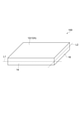
- FIG. 1 is a perspective view of a ceramic sintered body according to an embodiment.
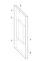
- FIG. 2 is a side view of the ceramic sintered body according to the embodiment.
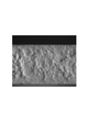
- FIG. 3 is an electron micrograph showing an example of chips remaining on the surface of the ceramic sintered body.
- FIG. 4 is a perspective view showing an example of a ceramic green sheet base material.
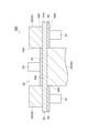
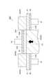
- FIG. 5 is a cross-sectional view of a ceramic green sheet base material and a cutting device showing a state before punching out the ceramic green sheet base material.
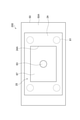
- FIG. 6 is a plan view of the cutting device.
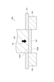
- FIG. 7 is a cross-sectional view of a ceramic green sheet base material and a cutting device showing a state after punching out the ceramic green sheet base material.
- FIG. 1 is a perspective view of a ceramic sintered body according to an embodiment.
- FIG. 2 is a side view of the ceramic sintered body according to the embodiment.
- FIG. 3 is an electron micrograph showing an example of chips remaining on the surface of the ceramic sintered body
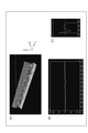
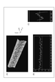
- FIG. 8 is an optical micrograph showing the side surface of the ceramic green sheet of Example 1 magnified 200 times.
- FIG. 9A is a photograph of a 3D image showing the side surface of the ceramic sintered body of Example 1.
- FIG. 9B is a graph showing the uneven shape measured along the center line that bisects the side surface along the Y direction.
- FIG. 9C is a graph showing the uneven shape of the side surface measured along the Z direction.
- FIG. 10 is a cross-sectional view of the cutting device used for punching the ceramic green sheet base material in Comparative Example 1.
- FIG. 11 is an optical micrograph showing the side surface of the ceramic green sheet of Comparative Example 1 magnified 200 times.
- FIG. 12A is a photograph of a 3D image showing the side surface of the ceramic sintered body of Comparative Example 1.
- FIG. 12B is a graph showing the uneven shape measured along the center line that divides the side surface in the Y direction.
- FIG. 12C is a graph showing the uneven shape of the side surface measured
- FIG. 1 is a perspective view of the ceramic sintered body 100.
- the ceramic sintered body 100 having a flat plate shape (rectangular parallelepiped shape) has a pair of main surfaces 12 parallel to each other, a pair of side surfaces 14 parallel to each other, and a pair of side surfaces 16 parallel to each other.
- the side surface 14 and the side surface 16 are orthogonal to each other.
- the center lines L1 and L2 (virtual lines) of the side surfaces 14 and 16 are both parallel to the main surface 12, and the side surfaces 14 and 16 are oriented in the thickness direction of the ceramic sintered body 100 (direction orthogonal to the main surface 12), respectively. It is divided into two.
- the central lines L1 and L2 are virtual lines, and the maximum height roughness (Rz) measured along the central lines L1 and L2 is 10 ⁇ m or less.
- the maximum height roughness (Rz) measured along the center lines L1 and L2 may be 6 ⁇ m or less, and may be 4 ⁇ m or less.
- the arithmetic mean roughness (Ra) measured along the center lines L1 and L2 may be 10 ⁇ m or less, and may be 2 ⁇ m or less.
- the maximum height roughness (Rz) and the arithmetic mean roughness (Ra) in the present disclosure are values measured in accordance with JIS B 0601: 2013, respectively.
- the maximum height roughness (Rz) measured along the center lines L1 and L2 may be 0.5 ⁇ m or more and 1 ⁇ m from the viewpoint of facilitating manufacturing and suppressing slipping when gripped. It may be the above. From the same viewpoint, the arithmetic mean roughness (Ra) measured along the center lines L1 and L2 may be 0.5 ⁇ m or more, or 1.0 ⁇ m or more. An example of the maximum height roughness (Rz) is 0.1 to 10 ⁇ m. An example of arithmetic mean roughness (Ra) is 0.5-10 ⁇ m.
- the maximum height roughness (Rz) and arithmetic mean roughness (Ra) measured along the center lines L1 and L2 on the pair of side surfaces 14 and the pair of side surfaces 16, that is, all of the four sides, are in the above range. It may be there. However, in some modifications, only one side surface (only side surface 14 or only side surface 16) may satisfy the above-mentioned maximum height roughness (Rz) and arithmetic mean roughness (Ra). Further, in some other modifications, only one pair of sides (only one pair of sides 14 or only one pair of sides 16) satisfies the above-mentioned maximum height roughness (Rz) and arithmetic mean roughness (Ra). It's okay.
- the thickness of the ceramic sintered body 100 may be 1.5 mm or less. As the thickness of the ceramic sintered body 100 becomes smaller, the areas of the side surfaces 14 and 16 also become smaller. Even if the areas of the side surfaces 14 and 16 are small, the quality will be affected if chips are generated during punching.
- the thickness of the ceramic sintered body 100 may be 0.3 mm or more.
- the ceramic sintered body 100 contains ceramic particles as a main component and oxide particles dispersed in the main component as subcomponents and different from the ceramic particles.
- the ceramic particles as the main component may contain at least one selected from the group consisting of nitrides, carbides, borides, oxides and silices.
- Examples of the oxide include aluminum oxide (Al 2 O 3 ) and the like.
- the ceramic particles may be made of a ceramic having aluminum as a constituent element from the viewpoint of achieving both excellent electrical insulation and high thermal conductivity, and may be, for example, aluminum nitride particles.
- the oxide particles dispersed in the above-mentioned main component contain an oxide different from the ceramic contained in the ceramic particles.
- the oxide particles may contain, for example, an oxide having at least one selected from the group consisting of rare earth elements, transition elements different from rare earth elements, alkaline earth metal elements, and aluminum elements as constituent elements. Such oxides have the effect of promoting the sintering of ceramic particles when used as a sintering aid.
- the oxide particles may contain an oxide derived from the sintering aid.
- the oxide contained in the oxide particles may be a composite oxide.
- the ceramic sintered body may contain aluminum nitride particles as a main component and oxide particles (composite oxide particles) having yttrium and aluminum as constituent elements as subcomponents. Such a ceramic sintered body is excellent not only in electrical insulation but also in thermal conductivity.
- the composite oxide contained in the sintered ceramic body 100 as a secondary component for example, 3Y 2 O 3 ⁇ 5Al 2 O 3 and Y 2 O 3 ⁇ Al 2 O 3.
- the main component in the present disclosure means the component having the highest content among the components contained in the ceramic sintered body.
- the sub-component in the present disclosure refers to a component contained in the ceramic sintered body 100 having a content smaller than that of the main component.
- the sub-component is a component different from the main component and is dispersed in the main component. For example, it may be contained in the grain boundaries of a plurality of ceramic particles which are the main components.
- the content of the main component in the ceramic sintered body 100 may be 90% by mass or more, 93% by mass or more, and 95% by mass or more from the viewpoint of fully exhibiting the characteristics of the main component. You may.
- the content of the secondary component (oxide particles different from the ceramic particles) in the ceramic sintered body may be 0.5% by mass or more from the viewpoint of promoting sintering and sufficiently increasing the density, and 1 mass by mass. % Or more, and may be 2% by mass or more.
- FIG. 2 is a side view of the ceramic sintered body 100 of FIG.
- the side surface 14 is composed of a shear section 30 and a fracture surface 32 adjacent to each other along a direction orthogonal to the main surface 12A and the main surface 12B.
- the shear section 30 and the fracture surface 32 are partitioned by a boundary line B.
- the shear section 30 is formed on the main surface 12A side, and the fracture surface 32 is formed on the main surface 12B side.
- the region 30A occupied by the shear cross section 30 is larger than the region 32A occupied by the fracture surface 32. That is, the area of the shear section 30 is larger than the area of the fracture surface 32.
- the center line L1 drawn so as to divide the side surface 14 of the ceramic sintered body 100 in the thickness direction is located on the shear cross section 30. Since the side surface 14 has a large area ratio of the sheared cross section 30, the chips remaining on the surface of the ceramic sintered body 100 can be sufficiently reduced.
- the area ratio of the region 30A occupied by the shear cross section 30 may be 70% or more, 75% or more, or 80% or more.
- the side surfaces other than the side surface 14 may have the same area ratio.
- the area ratio of the region 32A occupied by the fracture surface 32 may be 30% or less, 25% or less, or 20% or less.
- the side surfaces other than the side surface 14 may have the same area ratio. Each area ratio is obtained based on the area when the ceramic sintered body 100 is viewed from the side.
- the side surface 14 may be composed of only the shear section 30 and the fracture surface 32.
- the area ratio of the area 30A occupied by the shear cross section 30 and the area 32A occupied by the fracture surface 32 can be adjusted, for example, by changing the clearance between the die and the punch of the cutting device described later. When the clearance is reduced, the area ratio of the region 30A occupied by the shear cross section 30 tends to increase.
- FIG. 3 is an electron micrograph showing the chips 114 remaining on the surface 112 of the ceramic sintered body. As described above, if the chips 114 remain, it may not be possible to commercialize the product due to poor appearance, poor properties, or the like. Therefore, the yield of the ceramic sintered body is lowered. Since the remaining chips 114 are sufficiently reduced, the ceramic sintered body 100 of the present embodiment has a good appearance and can reduce variations in properties. As a result, the yield of commercialization can be increased.
- the manufacturing method of the present embodiment includes a manufacturing step of manufacturing a ceramic green sheet base material and a punching step of punching the ceramic green sheet base material using a cutting device including a die and a punch to obtain a ceramic green sheet. , A firing step of firing a ceramic green sheet to obtain a ceramic sintered body.
- raw materials for example, ceramic powder, sintering aid, and, if necessary, additives are used.
- the additive include a binder, a plasticizer, a dispersion medium, a mold release agent and the like.
- binder include a methylcellulose-based binder having a plasticity or a surface-active effect, and an acrylic acid ester-based binder having an excellent thermal decomposition property.
- plasticizer include glycerin.
- dispersion medium include ion-exchanged water and ethanol.
- the ceramic powder for example, aluminum nitride powder, silicon nitride powder, aluminum oxide powder, or the like can be used.
- the average particle size (median diameter) of the ceramic powder may be 0.1 to 6 ⁇ m, or may be 0.5 to 4 ⁇ m.
- an oxide having at least one selected from the group consisting of rare earth elements, transition elements different from rare earth elements, alkaline earth metal elements, and aluminum elements can be used.
- aluminum oxide, yttrium oxide, cerium oxide and the like can be mentioned. At least two of these oxides may form a composite oxide to form a liquid phase and promote sintering.
- the ceramic sintered body can be sufficiently densified.
- the composition of the oxide particles in the ceramic sintered body may be adjusted by changing the blending ratio of each oxide.
- the average particle size (median diameter) of the sintering aid may be 0.05 to 5 ⁇ m, or 0.1 to 3 ⁇ m.
- Ceramic powder, sintering aid, binder and additives added as needed are mixed and mixed to obtain a molding raw material.
- the molding raw material is applied to a release film to a predetermined thickness by a doctor blade method, a calendar method, an extrusion method, or the like, dried, and molded to obtain a ceramic green sheet base material.
- the release film may be a polyester film such as PET. After that, the release film is removed from the ceramic green sheet base material, and a punching step is performed in which the ceramic green sheet base material is punched out using a die equipped with a die and a punch.
- the ceramic green sheet base material 50 of FIG. 4 has a rectangular parallelepiped shape.
- the central portion of the ceramic green sheet base material 50 is punched out in the direction from one main surface 50B side to the main surface 50A side of the ceramic green sheet base material 50 to obtain a ceramic green sheet 53. That is, the ceramic green sheet 53 corresponds to a portion punched by the die.
- the ceramic sintered body 100 is obtained by firing the ceramic green sheet 53 obtained by punching with a die.
- the side surfaces 54 and 56 of the ceramic green sheet 53 are the side surfaces of the ceramic sintered body 100.
- the solid content of the ceramic green sheet base material 50 when punched with a die may be 65 to 85% by mass, or may be 75 to 85% by mass.
- the solid content is preferably adjusted by performing a drying step of drying the ceramic green sheet base material 50 before punching with a die.
- the shape of the ceramic green sheet base material is not limited to the shape shown in FIG.
- a strip-shaped ceramic green sheet base material may be unwound from a roll body in which the ceramic green sheet base material is wound into a roll shape and punched into a predetermined shape.
- the release film may be removed from the ceramic green sheet base material before punching with the cutting device, or the ceramic green sheet may be punched out using the cutting device with the release film attached to the ceramic green sheet base material. .. After that, the release film may be removed from the ceramic green sheet obtained by punching with a cutting device.
- a pushback type cutting device may be used.
- FIGS. 5, 6 and 7 show an example of a cutting device for punching the ceramic green sheet 53 from the ceramic green sheet base material 50 shown in FIG.
- FIG. 5 is a cross-sectional view of a cutting device 200 showing a state before punching out the ceramic green sheet base material 50.
- FIG. 6 is a plan view of the cutting device 200.
- FIG. 7 is a cross-sectional view of a cutting device 200 showing a state after punching out the ceramic green sheet base material 50.
- FIG. 5 shows a ceramic green sheet base material 50 before being punched by a cutting device 200 provided with a die 24 and a punch 22 as a die 20.
- the ceramic green sheet base material 50 is placed, the mounting plate 65 having a hole 65h through which the punch 22 is inserted, and the main surface of the ceramic green sheet base material 50.
- a ceramic green sheet base material is provided via a pressing plate 67 that is in contact with the central portion of 50A, a die 24 that is arranged so as to face the mounting plate 65 and is in contact with the periphery of the central portion of the main surface 50A, and a pressing plate 67.
- An elastic member 63 for urging the central portion of the main surface 50A of the 50 toward the punch 22 is provided. Further, the cutting device 200 is arranged below the mounting plate 65, and has an elastic member 61 that urges the end portion of the main surface 50A of the ceramic green sheet base material 50 toward the punch 22 via the mounting plate 65. Be prepared.
- the elastic members 61 and 63 may be, for example, springs.
- the die 24 shown in FIG. 5 is restricted from moving in the vertical direction, whereas the punch 22, the holding plate 67, and the elastic member 63 are configured to be movable in the vertical direction.
- the punching step of the ceramic green sheet base material 50 using the cutting device 200 can be performed, for example, by the following procedure. As shown in FIG. 5, the upper surface of the mounting plate 65 and the upper surface of the punch 22 are aligned at the same height. Further, the lower surface of the holding plate 67 and the lower surface of the die 24 are aligned at the same height.
- the upper surface of the mounting plate 65 and the lower surface of the die 24 are arranged so as to face each other at a predetermined interval, and the upper surface of the punch 22 and the lower surface of the pressing plate 67 are arranged so as to face each other at a predetermined interval.
- the predetermined interval at this time may be larger than the thickness of the ceramic green sheet base material 50.
- the ceramic green sheet base material 50 is placed on the upper surfaces of the mounting plate 65 and the punch 22. Then, as shown in FIG. 5, the punch 22 and the mounting plate 65 are raised together until the main surface 50A of the ceramic green sheet base material 50 comes into contact with the lower surface of the pressing plate 67 and the lower surface of the die 24. The die 24 is restricted from moving in the vertical direction.
- an elastic member 63 is provided on the upper side of the pressing plate 67, and the pressing plate 67 is configured to be urged downward by the elastic member 63 when it moves upward.
- the end portion 51a of the ceramic green sheet base material 50 moves upward by the die 24. Is regulated.
- the end portion 51a of the ceramic green sheet base material 50 is sandwiched between the die 24 and the mounting plate 65, and is urged toward the die 24 by the elastic member 61 via the mounting plate 65.
- the holding plate 67 moves upward as the punch 22 moves upward, and enters the through hole 25 composed of the die 24. As a result, the central portion 53a of the ceramic green sheet base material 50 is punched out.
- FIG. 7 is a diagram showing a state in which the central portion 53a of the ceramic green sheet base material 50 is punched out to obtain the ceramic green sheet 53 by moving the punch 22 upward (in the direction of arrow P1 in FIG. 7). ..
- the holding plate 67 moves upward while being urged downward by the elastic member 63.
- the elastic member 63 pressurizes the surface portion 53A with a predetermined pressure via the pressing plate 67.
- the elastic member 61 pressurizes the surface portion 51B of the end portion 51 (sheet in which the punched hole is formed) with a predetermined pressure via the mounting plate 65.
- the cutting device 200 urges the surface portion 53A on the side opposite to the surface portion 53B abutting on the punch 22 of the ceramic green sheet base material 50 toward the punch 22 with the elastic member 63, while urging the ceramic green.
- the sheet base material 50 is punched out.
- the central portion 53a of the ceramic green sheet base material 50 that is punched out while being urged toward the punch 22 becomes the ceramic green sheet 53.
- the maximum height roughness (Rz) of the side surface of the ceramic green sheet 53 is reduced.
- the maximum height roughness (Rz) of the side surface of the ceramic sintered body can be reduced.
- the lower side (surface portion 53B side) of the side surface 54 (56) of the ceramic green sheet 53 is a shear section, and the upper side (surface portion 53A side) is a fracture surface.
- the elastic member 63 and the holding plate 67 may be removed to collect the ceramic green sheet 53. As shown in FIG. 7, the ceramic green sheet 53 can be efficiently recovered by punching the ceramic green sheet 53 upward.
- the maximum height roughness (Rz) of the side surface of the ceramic green sheet 53 obtained in this way is sufficiently small.
- the fracture surface generated by punching can be sufficiently reduced. Therefore, the chips of the ceramic green sheet generated when the ceramic green sheet base material 50 is punched can be sufficiently reduced. Chips generated by punching adhere not only to the ceramic green sheet 53 but also to the die 20, the mounting plate 65, the holding plate 67, and the like. Since the die 20, the mounting plate 65, and the holding plate 67 are used repeatedly, the chips adhering to them will adhere to the ceramic green sheet to be punched out later. According to the manufacturing method of the present embodiment, since the generation of such chips is sufficiently reduced, the quality variation and yield of the ceramic sintered body 100 obtained by firing the ceramic green sheet 53 in the firing step are varied. Can be suppressed.
- the ceramic green sheet 53 may be degreased before firing the ceramic green sheet 53 in the firing step.
- the degreasing method is not particularly limited, and for example, the ceramic green sheet 53 may be heated to 300 to 700 ° C. in the air or in a non-oxidizing atmosphere such as nitrogen.
- the heating time may be, for example, 1 to 10 hours.
- the ceramic sintered body 100 can be obtained by firing the ceramic green sheet 53.
- the temperature is raised to, for example, 1760 to 1840 ° C. in an inert gas atmosphere.
- the holding time in the temperature range of 1760 to 1840 ° C. is, for example, 1 to 10 hours. Baking may be carried out under atmospheric pressure.
- the sintering conditions are set so that the densification of the sintered body proceeds sufficiently. It may be set appropriately.
- the ceramic sintered body 100 and the ceramic green sheet 53 are not limited to those having a rectangular main surface, and the main surface may have a polygonal shape other than a rectangular shape, or may be circular.
- the cutting device 200 shown in FIGS. 5, 6 and 7 is configured such that the punch 22 moves upward, but the punch 22 is not limited to this.
- the punch 22 may be configured to punch out the ceramic green sheet base material 50 by moving downward.
- the ceramic green sheet base material 50 may be punched out by using a cutting device such as the cutting device 200 shown in FIGS. 5 and 7 turned upside down.
- Example 1 Aluminum nitride powder (average particle size (median diameter): 1.2 ⁇ m), yttrium oxide powder (average particle size (median diameter): 0.6 ⁇ m), and aluminum oxide powder (average particle size (median diameter): 0. 25 ⁇ m) was blended in a mass ratio of 97: 1.5: 1.5 and mixed using a ball mill to obtain a mixed powder. 6 parts by mass of cellulose ether binder (manufactured by Shin-Etsu Chemical Co., Ltd., trade name: Metrose), 5 parts by mass of glycerin (manufactured by Kao Corporation, trade name: Exepearl), and ion exchange with respect to 100 parts by mass of the mixed powder. 10 parts by mass of water was added and mixed for 1 minute using a Henchel mixer to obtain a molding raw material. This molding raw material was molded by an extrusion molding method to prepare a ceramic green sheet base material (thickness: 1.2 mm).
- the solid content of the ceramic green sheet base material at the time of punching was 75% by mass.
- a spring was used as the elastic members 61 and 63 for urging the central portion and the end portion of the ceramic green sheet base material toward the punch 22 and the die 24, respectively.
- FIG. 8 is an optical micrograph showing the side surface of the ceramic green sheet magnified 200 times.
- the upper part of the side surface shown in FIG. 8 is a shear section, and the lower part is a fracture surface.
- Such a ceramic green sheet was degreased by heating in air at 570 ° C. for 5 hours.
- the degreased ceramic green sheet was placed in a heating furnace and heated to 1800 ° C. in a nitrogen gas atmosphere (atmospheric pressure).
- FIG. 9A is a photograph of a 3D image showing the side surface of the ceramic sintered body of Example 1.
- FIG. 9B is a graph showing the uneven shape measured along the center line that divides the side surface in the Y direction.
- FIG. 9C is a graph showing the uneven shape of the side surface measured along the Z direction.
- the maximum height roughness (Rz) obtained from the uneven shape shown in FIG. 9B was 2.5 ⁇ m.
- the arithmetic mean roughness (Ra) was in the range of 0.5 to 2 ⁇ m.
- FIG. 9C it was found that a part on the left side is a fracture surface and a part on the right side is a shear section. From this ratio, it was confirmed that about 80% of the entire side surface was a sheared cross section.
- the region ratios of Rz, Ra and shear sections on the other three sides of the ceramic sintered body were also similar to those shown in FIG. 9 (A).
- a total of 100 ceramic green sheets were prepared by repeatedly using the cutting device 200 in the same procedure, and fired in the same manner to produce a ceramic sintered body.
- the surface of the ceramic sintered body was visually inspected to check for the presence or absence of chips.
- the number of ceramic sintered bodies to which chips were attached was 3% of the total number.
- Example 1 A ceramic sintered body was produced in the same manner as in Example 1 except that the cutting device 250 shown in FIG. 10 was used instead of the cutting device 200.
- the central portion of the ceramic green sheet base material 151 placed on the die 120 was punched by moving the punch 130 downward (in the direction of arrow P2 in FIG. 10).
- the ceramic green sheet 153 punched by the punch 130 was not urged toward the punch 130 and freely fell into the collection container installed below the punch 130.
- FIG. 11 is an optical micrograph showing the side surface of the ceramic green sheet 153 obtained by punching out at a magnification of 200 times. Most of the side surfaces shown in FIG. 11 had a fracture surface. From the comparison between FIGS. 8 and 11, the side surface of the ceramic green sheet of Comparative Example 1 had larger unevenness than the side surface of the ceramic green sheet of Example 1. This ceramic green sheet was fired under the same conditions as in Example 1 to obtain a ceramic sintered body.
- FIG. 12A is a photograph of a 3D image showing the side surface of the ceramic sintered body of Comparative Example 1.
- FIG. 12B is a graph showing the uneven shape measured along the center line that divides the side surface in the Y direction.
- FIG. 12C is a graph showing the uneven shape of the side surface measured along the Z direction.
- the maximum height roughness (Rz) obtained from the uneven shape shown in FIG. 12B was about 20 ⁇ m. Further, according to the uneven shape shown in FIG. 12 (C), it was found that the boundary between the shear cross section and the fracture surface was not clear, and most of them were fracture surfaces. The distribution of Rz and fracture surface on the other three sides of the ceramic sintered body was also similar to that of the side shown in FIG. 12 (A).
- a total of 100 ceramic green sheets were prepared by repeatedly using the cutting device 250 in the same procedure, and fired in the same manner to produce a ceramic sintered body. The surface of the ceramic sintered body was visually inspected to check for the presence or absence of chips. As a result, the number of ceramic sintered bodies to which chips were attached was 5% of the total number.
- Example 1 From the comparison between Example 1 and Comparative Example 1, it was confirmed that the adhesion of chips can be reduced in Example 1 in which the maximum height roughness (Rz) of the side surface of the ceramic sintered body is small.
- Example 2 A ceramic green sheet was produced in the same manner as in Example 1 except that the clearance between the die 24 and the punch 22 in the cutting device was slightly wider than that in Example 1, to obtain a ceramic sintered body.
- the area ratio of the region occupied by the sheared cross section with respect to the entire side surface of the ceramic sintered body, the maximum height roughness (Rz), and the arithmetic mean roughness (Ra) were determined.
- the area ratio of the region occupied by the sheared surface was about 65%
- the maximum height roughness (Rz) was 3.0 ⁇ m.
- the arithmetic mean roughness (Ra) was in the range of 0.5 to 2 ⁇ m.
- a total of 100 ceramic sintered bodies were produced, and the presence or absence of chips was examined. As a result, the ratio of the ceramic sintered body to which the chips were attached was 4% of the total number.
- Example 3 The inner wall surface 24A of the die 24 in the cutting device of Example 1 was smoothed by using a grinding machine.
- a ceramic green sheet was produced in the same manner as in Example 1 except that this cutting device was used, and a ceramic sintered body was obtained.
- the area ratio of the region occupied by the sheared cross section with respect to the entire side surface of the ceramic sintered body, the maximum height roughness (Rz), and the arithmetic mean roughness (Ra) were determined. As a result, the area ratio of the region occupied by the sheared surface was about 80%, and the maximum height roughness (Rz) was 2.0 ⁇ m.
- the arithmetic mean roughness (Ra) was in the range of 0.5 to 2 ⁇ m.
- a total of 100 ceramic sintered bodies were produced, and the presence or absence of chips was examined.
- the ratio of the ceramic sintered body to which the chips were attached was 2% of the total number.
- a cutting blade capable of suppressing the generation of chips and a cutting device provided with the cutting blade are provided. Further, a manufacturing method capable of improving the quality and yield of the ceramic green sheet and the ceramic sintered body is provided. Further, a cutting method capable of improving the quality and yield of the workpiece to be cut is provided.
Landscapes
- Engineering & Computer Science (AREA)
- Chemical & Material Sciences (AREA)
- Ceramic Engineering (AREA)
- Manufacturing & Machinery (AREA)
- Structural Engineering (AREA)
- Materials Engineering (AREA)
- Organic Chemistry (AREA)
- Mechanical Engineering (AREA)
- Inorganic Chemistry (AREA)
- Devices For Post-Treatments, Processing, Supply, Discharge, And Other Processes (AREA)
Abstract
Provided is a flat-shaped ceramic sintered body 100 having a pair of principal planes 12, wherein an average value of the maximum height roughness (Rz) is 10 μm or less, the maximum height roughness (Rz) being measured along a center line L1 of a side surface 14 which is parallel to the pair of principal planes 12. Also provided is a method for producing a ceramic sintered body, the method comprising: a step for obtaining a ceramic green sheet by punching a ceramic green sheet substrate by means of a cutting device provided with a die and a punch; and a step for obtaining a ceramic sintered body by firing the ceramic green sheet, wherein the cutting device punches the ceramic green sheet substrate while biasing, toward the punch, a surface part of the ceramic green sheet substrate which is opposite to a surface part pressed by the punch.
Description
本開示は、セラミック焼結体、及びその製造方法に関する。
This disclosure relates to a ceramic sintered body and a method for manufacturing the same.
セラミックグリーンシートを所定の形状に加工する方法として、金型で打ち抜く方法が知られている。このような打ち抜き方法では、下方に移動してシートを打ち抜くシート打ち抜き用のパンチと、シート打ち抜きパンチの下方に配設されたシート打ち抜きダイとを備える金型を用いることが知られている。特許文献1では、パンチの下面に真空吸引穴を設け、真空吸引装置で吸引して打ち抜いたワークをパンチの下面に吸着維持する技術が開示されている。
As a method of processing a ceramic green sheet into a predetermined shape, a method of punching with a die is known. In such a punching method, it is known to use a die provided with a sheet punching punch that moves downward to punch a sheet and a sheet punching die disposed below the sheet punching punch. Patent Document 1 discloses a technique in which a vacuum suction hole is provided on the lower surface of a punch, and a work sucked and punched by a vacuum suction device is sucked and maintained on the lower surface of the punch.
特許文献1のように、金型を用いてセラミックグリーンシートを打ち抜くと、切屑が発生し、これが打ち抜かれたセラミックグリーシート又は金型に付着する場合がある。切屑が付着した状態でセラミックグリーンシートを焼成すると、最終的に得られるセラミック焼結体の表面に切屑が残存し、セラミック焼結体の品質のばらつき、及び歩留まり低下の要因となることが懸念される。
As in Patent Document 1, when a ceramic green sheet is punched out using a die, chips are generated, which may adhere to the punched out ceramic green sheet or die. When the ceramic green sheet is fired with chips attached, chips remain on the surface of the finally obtained ceramic sintered body, and there is a concern that the quality of the ceramic sintered body may vary and the yield may decrease. To.
そこで、本開示は、セラミックグリーンシートを打ち抜く際の切屑の発生を低減することによって、品質のばらつき及び歩留まりを向上することが可能なセラミック焼結体を提供する。また、本開示は、セラミックグリーンシートを打ち抜く際の切屑の発生を低減することによって、セラミック焼結体の品質のばらつき及び歩留まりを向上することが可能な製造方法を提供する。
Therefore, the present disclosure provides a ceramic sintered body capable of improving quality variation and yield by reducing the generation of chips when punching a ceramic green sheet. The present disclosure also provides a manufacturing method capable of improving the variation in quality and the yield of the ceramic sintered body by reducing the generation of chips when punching the ceramic green sheet.
本開示は、一対の主面を有する平板形状のセラミック焼結体であって、上記一対の主面と平行である、少なくとも一つの側面の中央線に沿って測定される最大高さ粗さ(Rz)が10μm以下であるセラミック焼結体を提供する。このようなセラミック焼結体は、側面において大きな凹凸が低減されているため、打ち抜きの際に発生する切屑の残存が十分に低減されている。よって、切屑の残存に伴う品質のばらつき及び歩留まりの低下を抑制することができる。
The present disclosure is a flat plate-shaped ceramic sintered body having a pair of main surfaces, the maximum height roughness measured along the center line of at least one side surface parallel to the pair of main surfaces. Provided is a ceramic sintered body having Rz) of 10 μm or less. In such a ceramic sintered body, large irregularities are reduced on the side surface, so that the residual chips generated during punching are sufficiently reduced. Therefore, it is possible to suppress the variation in quality and the decrease in yield due to the remaining chips.
上記側面は、上記一対の主面に直交する方向に沿って互いに隣り合う剪断面と破断面とを有し、側面の中央線は剪断面上に位置してよい。これによって、側面に占める剪断面の大きさを十分に大きくすることができる。したがって、打ち抜きの際に発生する切屑を一層低減することができる。よって、切屑の残存に伴う品質のばらつき及び歩留まりの低下を一層抑制することができる。
The side surface has a shear section and a fracture surface adjacent to each other along a direction orthogonal to the pair of main surfaces, and the center line of the side surface may be located on the shear section. This makes it possible to sufficiently increase the size of the shear cross section occupying the side surface. Therefore, it is possible to further reduce the chips generated during punching. Therefore, it is possible to further suppress the variation in quality and the decrease in yield due to the remaining chips.
上記側面において剪断面が占める領域の面積比率が70%以上であってよい。これによって、打ち抜きの際に発生する切屑をさらに低減することができる。よって、切屑の残存に伴う品質のばらつき及び歩留まりの低下をより一層抑制することができる。
The area ratio of the area occupied by the shear section on the above side surface may be 70% or more. This makes it possible to further reduce the chips generated during punching. Therefore, it is possible to further suppress the variation in quality and the decrease in yield due to the remaining chips.
上記最大高さ粗さ(Rz)は0.5μm以上であってよい。これによって、セラミック焼結体の製造が容易となり、歩留まりを一層向上することができる。
The maximum height roughness (Rz) may be 0.5 μm or more. This facilitates the production of the ceramic sintered body and can further improve the yield.
本開示は、ダイとパンチを備える切断装置を用いてセラミックグリーンシート基材を打ち抜いてセラミックグリーンシートを得る工程と、セラミックグリーンシートを焼成してセラミック焼結体を得る工程と、を有する、セラミック焼結体の製造方法であって、切断装置は、セラミックグリーンシート基材のパンチで押圧される表面部分とは反対側の表面部分を前記パンチに向かって付勢しながら前記セラミックグリーンシート基材を打ち抜く、セラミック焼結体の製造方法を提供する。
The present disclosure comprises a step of punching a ceramic green sheet substrate using a cutting device equipped with a die and a punch to obtain a ceramic green sheet, and a step of firing the ceramic green sheet to obtain a ceramic sintered body. In a method for manufacturing a sintered body, a cutting device uses a ceramic green sheet base material while urging a surface portion opposite to the surface portion pressed by the punch of the ceramic green sheet base material toward the punch. Provided is a method for producing a ceramic sintered body by punching.
この製造方法では、セラミックグリーンシート基材のパンチ側の表面部分とは反対側の表面部分をパンチに向かって付勢しながらセラミックグリーンシート基材を打ち抜く切断装置を用いている。このため、打ち抜きの際に生じる破断面を低減し、切屑の発生を十分に低減することができる。このように、切屑の発生が十分に低減されていることから、セラミックグリーンシートを焼成して得られるセラミック焼結体の品質のばらつき及び歩留まりの低下を抑制することができる。
This manufacturing method uses a cutting device that punches out the ceramic green sheet base material while urging the surface portion on the opposite side of the surface portion on the punch side of the ceramic green sheet base material toward the punch. Therefore, it is possible to reduce the fracture surface generated during punching and sufficiently reduce the generation of chips. As described above, since the generation of chips is sufficiently reduced, it is possible to suppress the variation in quality and the decrease in yield of the ceramic sintered body obtained by firing the ceramic green sheet.
上記製造方法によって製造されるセラミック焼結体は一対の主面を有する平板形状であり、上記一対の主面と平行である、少なくとも一つの側面の中央線に沿って測定される最大高さ粗さ(Rz)が10μm以下であってもよい。このようなセラミック焼結体は、側面における大きな凹凸が低減されているため、打ち抜きの際に発生する切屑を十分に低減することができる。
The ceramic sintered body manufactured by the above manufacturing method has a flat plate shape having a pair of main surfaces, and has a maximum height roughness measured along the center line of at least one side surface parallel to the pair of main surfaces. The (Rz) may be 10 μm or less. Since such a ceramic sintered body has reduced large irregularities on the side surface, it is possible to sufficiently reduce chips generated during punching.
セラミック焼結体の側面は、上記一対の主面に直交する方向に沿って互いに隣り合う剪断面と破断面とを有し、側面において剪断面が占める領域の面積比率が70%以上であってよい。セラミック焼結体が上述のような側面を有するようにセラミックグリーンシート基材を打ち抜くことによって、切屑の発生を一層抑制することができる。
The side surface of the ceramic sintered body has a shear section and a fracture surface adjacent to each other along a direction orthogonal to the pair of main surfaces, and the area ratio of the region occupied by the shear section on the side surface is 70% or more. good. By punching the ceramic green sheet base material so that the ceramic sintered body has the above-mentioned side surfaces, the generation of chips can be further suppressed.
上記切断装置で打ち抜かれる際のセラミックグリーンシート基材の固形分の含有量が65~85質量%であってよい。このようなセラミックグリーンシート基材を用いることによって、打ち抜く工程で生じる破断面を一層低減し、セラミックグリーンシートの側面における凹凸を一層低減することができる。これによって、セラミックグリーンシート基材を打ち抜く際の切屑の発生を一層低減することができる。
The solid content of the ceramic green sheet base material when punched by the cutting device may be 65 to 85% by mass. By using such a ceramic green sheet base material, it is possible to further reduce the fracture surface generated in the punching process and further reduce the unevenness on the side surface of the ceramic green sheet. This makes it possible to further reduce the generation of chips when punching out the ceramic green sheet base material.
本開示は、セラミックグリーンシートを打ち抜く際の切屑の発生を低減することによって、品質のばらつき及び歩留まりを向上することが可能なセラミック焼結体を提供することができる。また、本開示は、セラミックグリーンシートを打ち抜く際の切屑の発生を低減することによって、セラミック焼結体の品質のばらつき及び歩留まりを向上することが可能な製造方法を提供することができる。
The present disclosure can provide a ceramic sintered body capable of improving quality variation and yield by reducing the generation of chips when punching a ceramic green sheet. Further, the present disclosure can provide a manufacturing method capable of improving the variation in quality and the yield of the ceramic sintered body by reducing the generation of chips when punching the ceramic green sheet.
以下、場合により図面を参照して、本開示の実施形態について説明する。ただし、以下の実施形態は、本開示を説明するための例示であり、本開示を以下の内容に限定する趣旨ではない。説明において、同一要素又は同一機能を有する要素には同一の符号を付し、重複する説明を省略する。また、説明に使用される上下左右等の位置関係は、特に断らない限り、図面に示す位置関係に基づくものとする。
Hereinafter, embodiments of the present disclosure will be described with reference to the drawings as the case may be. However, the following embodiments are examples for explaining the present disclosure, and are not intended to limit the present disclosure to the following contents. In the description, the same elements or elements having the same function are designated by the same reference numerals, and duplicate description will be omitted. In addition, the positional relationship such as up, down, left, and right used in the explanation shall be based on the positional relationship shown in the drawings unless otherwise specified.
図1は、セラミック焼結体100の斜視図である。平板形状(直方体形状)を有するセラミック焼結体100は、互いに平行である一対の主面12と、互いに平行である一対の側面14と、互いに平行である一対の側面16と、を有する。側面14と側面16は互いに直交している。側面14,16の中央線L1,L2(仮想線)は、ともに主面12と平行であり、それぞれ側面14,16をセラミック焼結体100の厚さ方向(主面12に直交する方向)に二分している。
FIG. 1 is a perspective view of the ceramic sintered body 100. The ceramic sintered body 100 having a flat plate shape (rectangular parallelepiped shape) has a pair of main surfaces 12 parallel to each other, a pair of side surfaces 14 parallel to each other, and a pair of side surfaces 16 parallel to each other. The side surface 14 and the side surface 16 are orthogonal to each other. The center lines L1 and L2 (virtual lines) of the side surfaces 14 and 16 are both parallel to the main surface 12, and the side surfaces 14 and 16 are oriented in the thickness direction of the ceramic sintered body 100 (direction orthogonal to the main surface 12), respectively. It is divided into two.
中央線L1,L2は仮想線であり、この中央線L1,L2に沿って測定される最大高さ粗さ(Rz)は10μm以下である。このような側面14,16を有するセラミック焼結体100は、切屑の残存が十分に低減されている。よって、切屑の残存に伴う品質のばらつき及び歩留まりの低下を抑制することができる。切屑の残存を一層低減する観点から、中央線L1,L2に沿って測定される最大高さ粗さ(Rz)は6μm以下であってよく、4μm以下であってもよい。同様の観点から、中央線L1,L2に沿って測定される算術平均粗さ(Ra)は、10μm以下であってよく、2μm以下であってもよい。本開示における最大高さ粗さ(Rz)及び算術平均粗さ(Ra)は、それぞれ、JIS B 0601:2013に準拠して測定される値である。
The central lines L1 and L2 are virtual lines, and the maximum height roughness (Rz) measured along the central lines L1 and L2 is 10 μm or less. In the ceramic sintered body 100 having such side surfaces 14 and 16, the residual chips are sufficiently reduced. Therefore, it is possible to suppress the variation in quality and the decrease in yield due to the remaining chips. From the viewpoint of further reducing the residual chips, the maximum height roughness (Rz) measured along the center lines L1 and L2 may be 6 μm or less, and may be 4 μm or less. From the same viewpoint, the arithmetic mean roughness (Ra) measured along the center lines L1 and L2 may be 10 μm or less, and may be 2 μm or less. The maximum height roughness (Rz) and the arithmetic mean roughness (Ra) in the present disclosure are values measured in accordance with JIS B 0601: 2013, respectively.
中央線L1,L2に沿って測定される最大高さ粗さ(Rz)は、製造を容易にする観点及び把持した際に滑り落ちることを抑制する観点から、0.5μm以上であってよく、1μm以上であってもよい。同様の観点から、中央線L1,L2に沿って測定される算術平均粗さ(Ra)は、0.5μm以上であってよく、1.0μm以上であってもよい。最大高さ粗さ(Rz)の一例は、0.1~10μmである。算術平均粗さ(Ra)の一例は0.5~10μmである。
The maximum height roughness (Rz) measured along the center lines L1 and L2 may be 0.5 μm or more and 1 μm from the viewpoint of facilitating manufacturing and suppressing slipping when gripped. It may be the above. From the same viewpoint, the arithmetic mean roughness (Ra) measured along the center lines L1 and L2 may be 0.5 μm or more, or 1.0 μm or more. An example of the maximum height roughness (Rz) is 0.1 to 10 μm. An example of arithmetic mean roughness (Ra) is 0.5-10 μm.
一対の側面14及び一対の側面16、すなわち四方の側面の全てにおいて、中央線L1,L2に沿って測定される最大高さ粗さ(Rz)及び算術平均粗さ(Ra)が上述の範囲であってよい。ただし、幾つかの変形例では、一つの側面のみ(側面14のみ又は側面16のみ)が、上述の最大高さ粗さ(Rz)及び算術平均粗さ(Ra)を満たしてよい。また、別の幾つかの変形例では、一対の側面のみ(一対の側面14のみ又は一対の側面16のみ)が、上述の最大高さ粗さ(Rz)及び算術平均粗さ(Ra)を満たしてよい。
The maximum height roughness (Rz) and arithmetic mean roughness (Ra) measured along the center lines L1 and L2 on the pair of side surfaces 14 and the pair of side surfaces 16, that is, all of the four sides, are in the above range. It may be there. However, in some modifications, only one side surface (only side surface 14 or only side surface 16) may satisfy the above-mentioned maximum height roughness (Rz) and arithmetic mean roughness (Ra). Further, in some other modifications, only one pair of sides (only one pair of sides 14 or only one pair of sides 16) satisfies the above-mentioned maximum height roughness (Rz) and arithmetic mean roughness (Ra). It's okay.
セラミック焼結体100の厚みは、1.5mm以下であってよい。セラミック焼結体100の厚みが小さくなると、側面14,16の面積も小さくなる。側面14,16の面積が小さい場合であっても、打ち抜きの際に切屑が発生すると品質に影響を及ぼす。なお、セラミック焼結体100の厚みは0.3mm以上であってよい。
The thickness of the ceramic sintered body 100 may be 1.5 mm or less. As the thickness of the ceramic sintered body 100 becomes smaller, the areas of the side surfaces 14 and 16 also become smaller. Even if the areas of the side surfaces 14 and 16 are small, the quality will be affected if chips are generated during punching. The thickness of the ceramic sintered body 100 may be 0.3 mm or more.
セラミック焼結体100は、主成分としてセラミック粒子と、副成分として主成分中に分散し、セラミック粒子とは異なる酸化物粒子と、を含む。主成分であるセラミック粒子は、窒化物、炭化物、硼化物、酸化物及び珪化物からなる群より選ばれる少なくとも一種を含んでいてよい。窒化物としては、窒化アルミニウム(AlN)及び窒化ケイ素(Si3N4)が挙げられる。酸化物としては、酸化アルミニウム(Al2O3)等が挙げられる。セラミック粒子は、優れた電気絶縁性と高い熱伝導率とを両立する観点から、構成元素としてアルミニウムを有するセラミックで構成されていてよく、例えば窒化アルミニウム粒子であってもよい。
The ceramic sintered body 100 contains ceramic particles as a main component and oxide particles dispersed in the main component as subcomponents and different from the ceramic particles. The ceramic particles as the main component may contain at least one selected from the group consisting of nitrides, carbides, borides, oxides and silices. The nitrides, aluminum nitride (AlN) and silicon nitride (Si 3 N 4). Examples of the oxide include aluminum oxide (Al 2 O 3 ) and the like. The ceramic particles may be made of a ceramic having aluminum as a constituent element from the viewpoint of achieving both excellent electrical insulation and high thermal conductivity, and may be, for example, aluminum nitride particles.
副成分として、上述の主成分中に分散する酸化物粒子は、セラミック粒子に含まれるセラミックとは異なる酸化物を含有する。酸化物粒子は、例えば、希土類元素、希土類元素とは異なる遷移元素、アルカリ土類金属元素、及びアルミニウム元素からなる群より選ばれる少なくとも一種を構成元素とする酸化物を含んでいてよい。このような酸化物は、焼結助剤として用いられたときに、セラミック粒子の焼結を促進する作用を有する。
As a sub-component, the oxide particles dispersed in the above-mentioned main component contain an oxide different from the ceramic contained in the ceramic particles. The oxide particles may contain, for example, an oxide having at least one selected from the group consisting of rare earth elements, transition elements different from rare earth elements, alkaline earth metal elements, and aluminum elements as constituent elements. Such oxides have the effect of promoting the sintering of ceramic particles when used as a sintering aid.
このように、酸化物粒子は、焼結助剤に由来する酸化物を含んでよい。酸化物粒子に含まれる酸化物は複合酸化物であってよい。一例として、セラミック焼結体は、主成分として窒化アルミニウム粒子と、副成分として構成元素としてイットリウム及びアルミニウムを有する酸化物粒子(複合酸化物粒子)と、を含んでいてよい。このようなセラミック焼結体は、電気絶縁性のみならず、熱伝導性にも優れる。副成分としてセラミック焼結体100に含まれる複合酸化物としては、例えば、3Y2O3・5Al2O3及びY2O3・Al2O3が挙げられる。
As described above, the oxide particles may contain an oxide derived from the sintering aid. The oxide contained in the oxide particles may be a composite oxide. As an example, the ceramic sintered body may contain aluminum nitride particles as a main component and oxide particles (composite oxide particles) having yttrium and aluminum as constituent elements as subcomponents. Such a ceramic sintered body is excellent not only in electrical insulation but also in thermal conductivity. As the composite oxide contained in the sintered ceramic body 100 as a secondary component, for example, 3Y 2 O 3 · 5Al 2 O 3 and Y 2 O 3 · Al 2 O 3.
本開示における主成分とは、セラミック焼結体に含まれる成分のうち、最も含有量が多い成分をいう。本開示における副成分とは、セラミック焼結体100に含まれる成分のうち、主成分よりも含有量が少ない成分をいう。副成分は、主成分とは異なる成分であり、主成分中に分散している。例えば、主成分である複数のセラミック粒子の粒界に含まれていてよい。セラミック焼結体100における主成分の含有量は、主成分の有する特性を十分に発揮させる観点から、90質量%以上であってよく、93質量%以上であってよく、95質量%以上であってもよい。セラミック焼結体における副成分(セラミック粒子とは異なる酸化物粒子)の含有量は、焼結を促進して密度を十分に高くする観点から、0.5質量%以上であってよく、1質量%以上であってよく、2質量%以上であってもよい。
The main component in the present disclosure means the component having the highest content among the components contained in the ceramic sintered body. The sub-component in the present disclosure refers to a component contained in the ceramic sintered body 100 having a content smaller than that of the main component. The sub-component is a component different from the main component and is dispersed in the main component. For example, it may be contained in the grain boundaries of a plurality of ceramic particles which are the main components. The content of the main component in the ceramic sintered body 100 may be 90% by mass or more, 93% by mass or more, and 95% by mass or more from the viewpoint of fully exhibiting the characteristics of the main component. You may. The content of the secondary component (oxide particles different from the ceramic particles) in the ceramic sintered body may be 0.5% by mass or more from the viewpoint of promoting sintering and sufficiently increasing the density, and 1 mass by mass. % Or more, and may be 2% by mass or more.
図2は、図1のセラミック焼結体100の側面図である。側面14は、主面12A及び主面12Bに直交する方向に沿って互いに隣り合う剪断面30と破断面32とで構成される。剪断面30と破断面32は、境界線Bで区画される。剪断面30は主面12A側に形成され、破断面32は主面12B側に形成されている。側面14では、剪断面30が占める領域30Aの方が、破断面32が占める領域32Aよりも大きい。すなわち、剪断面30の面積の方が破断面32の面積よりも大きい。このため、セラミック焼結体100の側面14を厚さ方向に二分するように描かれる中央線L1は、剪断面30上に位置している。側面14は、剪断面30の面積割合が大きいことから、セラミック焼結体100の表面に残存する切屑を十分に低減することができる。
FIG. 2 is a side view of the ceramic sintered body 100 of FIG. The side surface 14 is composed of a shear section 30 and a fracture surface 32 adjacent to each other along a direction orthogonal to the main surface 12A and the main surface 12B. The shear section 30 and the fracture surface 32 are partitioned by a boundary line B. The shear section 30 is formed on the main surface 12A side, and the fracture surface 32 is formed on the main surface 12B side. On the side surface 14, the region 30A occupied by the shear cross section 30 is larger than the region 32A occupied by the fracture surface 32. That is, the area of the shear section 30 is larger than the area of the fracture surface 32. Therefore, the center line L1 drawn so as to divide the side surface 14 of the ceramic sintered body 100 in the thickness direction is located on the shear cross section 30. Since the side surface 14 has a large area ratio of the sheared cross section 30, the chips remaining on the surface of the ceramic sintered body 100 can be sufficiently reduced.
側面14において、剪断面30が占める領域30Aの面積比率は70%以上であってよく、75%以上であってよく、80%以上であってもよい。側面14以外の側面も同様の面積比率であってよい。側面14において、破断面32が占める領域32Aの面積比率は、30%以下であってよく、25%以下であってよく、20%以下であってもよい。側面14以外の側面も同様の面積比率であってよい。各面積比率は、セラミック焼結体100を側面視したときの面積に基づいて求められる。側面14は、剪断面30及び破断面32のみによって構成されてよい。なお、剪断面30が占める領域30Aと破断面32が占める領域32Aの面積比率は、例えば、後述する切断装置のダイとパンチのクリアランスを変えることで調整することができる。クリアランスを小さくすると、剪断面30が占める領域30Aの面積比率は大きくなる傾向にある。
On the side surface 14, the area ratio of the region 30A occupied by the shear cross section 30 may be 70% or more, 75% or more, or 80% or more. The side surfaces other than the side surface 14 may have the same area ratio. On the side surface 14, the area ratio of the region 32A occupied by the fracture surface 32 may be 30% or less, 25% or less, or 20% or less. The side surfaces other than the side surface 14 may have the same area ratio. Each area ratio is obtained based on the area when the ceramic sintered body 100 is viewed from the side. The side surface 14 may be composed of only the shear section 30 and the fracture surface 32. The area ratio of the area 30A occupied by the shear cross section 30 and the area 32A occupied by the fracture surface 32 can be adjusted, for example, by changing the clearance between the die and the punch of the cutting device described later. When the clearance is reduced, the area ratio of the region 30A occupied by the shear cross section 30 tends to increase.
図3は、セラミック焼結体の表面112に残存する切屑114を示す電子顕微鏡写真である。このように、切屑114が残存すると、外観不良、又は性状不良等によって、製品化できなくなる場合がある。このため、セラミック焼結体の歩留まりが低下する。本実施形態のセラミック焼結体100は、残存する切屑114が十分に低減されていることから、良好な外観を有し、且つ、性状のばらつきを低減することができる。その結果、製品化の歩留まりを高くすることができる。
FIG. 3 is an electron micrograph showing the chips 114 remaining on the surface 112 of the ceramic sintered body. As described above, if the chips 114 remain, it may not be possible to commercialize the product due to poor appearance, poor properties, or the like. Therefore, the yield of the ceramic sintered body is lowered. Since the remaining chips 114 are sufficiently reduced, the ceramic sintered body 100 of the present embodiment has a good appearance and can reduce variations in properties. As a result, the yield of commercialization can be increased.
一実施形態に係るセラミック焼結体の製造方法を説明する。本実施形態の製造方法は、セラミックグリーンシート基材を作製する作製工程と、ダイとパンチを含む金型を備える切断装置を用いてセラミックグリーンシート基材を打ち抜いてセラミックグリーンシートを得る打ち抜き工程と、セラミックグリーンシートを焼成してセラミック焼結体を得る焼成工程と、を有する。
A method for manufacturing a ceramic sintered body according to an embodiment will be described. The manufacturing method of the present embodiment includes a manufacturing step of manufacturing a ceramic green sheet base material and a punching step of punching the ceramic green sheet base material using a cutting device including a die and a punch to obtain a ceramic green sheet. , A firing step of firing a ceramic green sheet to obtain a ceramic sintered body.
作製工程では、まず、原料を準備する。原料としては、例えば、セラミック粉末、焼結助剤、及び、必要に応じて添加剤を用いる。添加剤としては、バインダー、可塑剤、分散媒、及び離型剤等が挙げられる。バインダーとしては、例えば、可塑性又は界面活性効果を有するメチルセルロース系のもの、熱分解性に優れたアクリル酸エステル系のものが挙げられる。可塑剤としては、例えばグリセリンが挙げられる。分散媒としては、イオン交換水及びエタノール等が挙げられる。セラミック粉末としては、例えば、窒化アルミニウム粉末、窒化ケイ素粉末、又は酸化アルミニウム粉末等を用いることができる。セラミック粉末の平均粒径(メジアン径)は、0.1~6μmであってよく、0.5~4μmであってもよい。
In the manufacturing process, first, prepare the raw materials. As raw materials, for example, ceramic powder, sintering aid, and, if necessary, additives are used. Examples of the additive include a binder, a plasticizer, a dispersion medium, a mold release agent and the like. Examples of the binder include a methylcellulose-based binder having a plasticity or a surface-active effect, and an acrylic acid ester-based binder having an excellent thermal decomposition property. Examples of the plasticizer include glycerin. Examples of the dispersion medium include ion-exchanged water and ethanol. As the ceramic powder, for example, aluminum nitride powder, silicon nitride powder, aluminum oxide powder, or the like can be used. The average particle size (median diameter) of the ceramic powder may be 0.1 to 6 μm, or may be 0.5 to 4 μm.
焼結助剤としては、希土類元素、希土類元素とは異なる遷移元素、アルカリ土類金属元素、及びアルミニウム元素からなる群より選ばれる少なくとも一種を構成元素とする酸化物を用いることができる。例えば、酸化アルミニウム、酸化イットリウム、及び酸化セリウム等が挙げられる。これらの酸化物の少なくとも2つは複合酸化物となって液相を形成して焼結を促進してもよい。これによって、セラミック焼結体を十分に緻密化することができる。複数の酸化物を用いる場合は、各酸化物の配合割合を変えて、セラミック焼結体における酸化物粒子の組成を調整してもよい。焼結助剤の平均粒径(メジアン径)は、0.05~5μmであってよく、0.1~3μmであってもよい。
As the sintering aid, an oxide having at least one selected from the group consisting of rare earth elements, transition elements different from rare earth elements, alkaline earth metal elements, and aluminum elements can be used. For example, aluminum oxide, yttrium oxide, cerium oxide and the like can be mentioned. At least two of these oxides may form a composite oxide to form a liquid phase and promote sintering. Thereby, the ceramic sintered body can be sufficiently densified. When a plurality of oxides are used, the composition of the oxide particles in the ceramic sintered body may be adjusted by changing the blending ratio of each oxide. The average particle size (median diameter) of the sintering aid may be 0.05 to 5 μm, or 0.1 to 3 μm.
セラミック粉末、焼結助剤、バインダー及び必要に応じて添加される添加剤を配合して混合し、成形原料を得る。成形原料を、ドクターブレード法、カレンダー法、又は押し出し法等によって離型フィルム上に所定の厚みで塗布して乾燥し、成形してセラミックグリーンシート基材を得る。離型フィルムは、例えばPET等のポリエステルフィルムであってよい。その後、セラミックグリーンシート基材から離型フィルムを取り外し、ダイとパンチを備える金型を用いてセラミックグリーンシート基材を打ち抜く打ち抜き工程を行う。
Ceramic powder, sintering aid, binder and additives added as needed are mixed and mixed to obtain a molding raw material. The molding raw material is applied to a release film to a predetermined thickness by a doctor blade method, a calendar method, an extrusion method, or the like, dried, and molded to obtain a ceramic green sheet base material. The release film may be a polyester film such as PET. After that, the release film is removed from the ceramic green sheet base material, and a punching step is performed in which the ceramic green sheet base material is punched out using a die equipped with a die and a punch.
図4のセラミックグリーンシート基材50は、直方体形状を有する。セラミックグリーンシート基材50の一方の主面50B側から主面50A側に向かう方向にセラミックグリーンシート基材50の中央部分を打ち抜いて、セラミックグリーンシート53を得る。すなわち、セラミックグリーンシート53は、金型によって打ち抜かれる部分に相当する。金型で打ち抜かれて得られるセラミックグリーンシート53を焼成するとセラミック焼結体100が得られる。セラミックグリーンシート53の側面54,56が、セラミック焼結体100の側面となる。
The ceramic green sheet base material 50 of FIG. 4 has a rectangular parallelepiped shape. The central portion of the ceramic green sheet base material 50 is punched out in the direction from one main surface 50B side to the main surface 50A side of the ceramic green sheet base material 50 to obtain a ceramic green sheet 53. That is, the ceramic green sheet 53 corresponds to a portion punched by the die. The ceramic sintered body 100 is obtained by firing the ceramic green sheet 53 obtained by punching with a die. The side surfaces 54 and 56 of the ceramic green sheet 53 are the side surfaces of the ceramic sintered body 100.
金型で打ち抜かれる際のセラミックグリーンシート基材50の固形分の含有量は、65~85質量%であってよく、75~85質量%であってもよい。固形分の含有量は、金型で打ち抜く前に、セラミックグリーンシート基材50を乾燥する乾燥工程を行って調節することが好ましい。
The solid content of the ceramic green sheet base material 50 when punched with a die may be 65 to 85% by mass, or may be 75 to 85% by mass. The solid content is preferably adjusted by performing a drying step of drying the ceramic green sheet base material 50 before punching with a die.
セラミックグリーンシート基材の形状は図4の形状に限定されない。例えば、セラミックグリーンシート基材がロール状に巻かれたロール体から帯状のセラミックグリーンシート基材を繰り出し、所定の形状に打ち抜いてもよい。切断装置で打ち抜く前にセラミックグリーンシート基材から離型フィルムを取り外してもよいし、離型フィルムをセラミックグリーンシート基材に貼り合わせた状態で切断装置を用いてセラミックグリーンシートを打ち抜いてもよい。その後、切断装置で打ち抜いて得られたセラミックグリーンシートから離型フィルムを取り外してもよい。切断装置はプッシュバック方式のものを用いてよい。
The shape of the ceramic green sheet base material is not limited to the shape shown in FIG. For example, a strip-shaped ceramic green sheet base material may be unwound from a roll body in which the ceramic green sheet base material is wound into a roll shape and punched into a predetermined shape. The release film may be removed from the ceramic green sheet base material before punching with the cutting device, or the ceramic green sheet may be punched out using the cutting device with the release film attached to the ceramic green sheet base material. .. After that, the release film may be removed from the ceramic green sheet obtained by punching with a cutting device. A pushback type cutting device may be used.
図5,図6及び図7は、図4に示すセラミックグリーンシート基材50からセラミックグリーンシート53を打ち抜く切断装置の一例を示している。図5は、セラミックグリーンシート基材50を打ち抜く前の状態を示す切断装置200の断面図である。図6は、切断装置200の平面図である。図7は、セラミックグリーンシート基材50を打ち抜いた後の状態を示す切断装置200の断面図である。
FIGS. 5, 6 and 7 show an example of a cutting device for punching the ceramic green sheet 53 from the ceramic green sheet base material 50 shown in FIG. FIG. 5 is a cross-sectional view of a cutting device 200 showing a state before punching out the ceramic green sheet base material 50. FIG. 6 is a plan view of the cutting device 200. FIG. 7 is a cross-sectional view of a cutting device 200 showing a state after punching out the ceramic green sheet base material 50.
図5には、金型20としてダイ24及びパンチ22を備える切断装置200で打ち抜かれる前のセラミックグリーンシート基材50が示されている。図5及び図6に示すように、切断装置200は、セラミックグリーンシート基材50が載置され、パンチ22が挿通する穴65hを有する載置板65と、セラミックグリーンシート基材50の主面50Aの中央部分と接する押さえ板67と、載置板65と対向するように配置され、主面50Aの当該中央部分の周囲と接するダイ24と、押さえ板67を介して、セラミックグリーンシート基材50の主面50Aの中央部をパンチ22に向かって付勢する弾性部材63を備える。また、切断装置200は、載置板65の下方に配置され、載置板65を介してセラミックグリーンシート基材50の主面50Aの端部をパンチ22に向かって付勢する弾性部材61を備える。弾性部材61,63は、例えばばねであってよい。
FIG. 5 shows a ceramic green sheet base material 50 before being punched by a cutting device 200 provided with a die 24 and a punch 22 as a die 20. As shown in FIGS. 5 and 6, in the cutting device 200, the ceramic green sheet base material 50 is placed, the mounting plate 65 having a hole 65h through which the punch 22 is inserted, and the main surface of the ceramic green sheet base material 50. A ceramic green sheet base material is provided via a pressing plate 67 that is in contact with the central portion of 50A, a die 24 that is arranged so as to face the mounting plate 65 and is in contact with the periphery of the central portion of the main surface 50A, and a pressing plate 67. An elastic member 63 for urging the central portion of the main surface 50A of the 50 toward the punch 22 is provided. Further, the cutting device 200 is arranged below the mounting plate 65, and has an elastic member 61 that urges the end portion of the main surface 50A of the ceramic green sheet base material 50 toward the punch 22 via the mounting plate 65. Be prepared. The elastic members 61 and 63 may be, for example, springs.
図5に示すダイ24は、上下方向の移動が規制されているのに対し、パンチ22、押さえ板67及び弾性部材63は、上下方向に沿って移動可能に構成される。切断装置200を用いるセラミックグリーンシート基材50の打ち抜き工程は、例えば以下の手順で行うことができる。図5に示されるように、載置板65の上面とパンチ22の上面とを同じ高さに揃える。また、押さえ板67の下面とダイ24の下面を同じ高さに揃える。載置板65の上面とダイ24の下面とが所定の間隔で互いに対向するように配置され、パンチ22の上面と押さえ板67の下面とが所定の間隔で互いに対向するように配置される。このときの所定の間隔は、セラミックグリーンシート基材50の厚みよりも大きくてよい。
The die 24 shown in FIG. 5 is restricted from moving in the vertical direction, whereas the punch 22, the holding plate 67, and the elastic member 63 are configured to be movable in the vertical direction. The punching step of the ceramic green sheet base material 50 using the cutting device 200 can be performed, for example, by the following procedure. As shown in FIG. 5, the upper surface of the mounting plate 65 and the upper surface of the punch 22 are aligned at the same height. Further, the lower surface of the holding plate 67 and the lower surface of the die 24 are aligned at the same height. The upper surface of the mounting plate 65 and the lower surface of the die 24 are arranged so as to face each other at a predetermined interval, and the upper surface of the punch 22 and the lower surface of the pressing plate 67 are arranged so as to face each other at a predetermined interval. The predetermined interval at this time may be larger than the thickness of the ceramic green sheet base material 50.
載置板65及びパンチ22の上面上に、セラミックグリーンシート基材50を載置する。その後、図5に示すように、セラミックグリーンシート基材50の主面50Aが、押さえ板67の下面及びダイ24の下面に接するまでパンチ22及び載置板65を一緒に上昇させる。ダイ24は上下方向の移動が規制されている。一方、押さえ板67の上側には、弾性部材63が設けられており、押さえ板67は上方に移動すると弾性部材63によって下方に付勢されるように構成されている。
The ceramic green sheet base material 50 is placed on the upper surfaces of the mounting plate 65 and the punch 22. Then, as shown in FIG. 5, the punch 22 and the mounting plate 65 are raised together until the main surface 50A of the ceramic green sheet base material 50 comes into contact with the lower surface of the pressing plate 67 and the lower surface of the die 24. The die 24 is restricted from moving in the vertical direction. On the other hand, an elastic member 63 is provided on the upper side of the pressing plate 67, and the pressing plate 67 is configured to be urged downward by the elastic member 63 when it moves upward.
図5に示すようにセラミックグリーンシート基材50の主面50Aが、押さえ板67の下面及びダイ24の下面に接すると、セラミックグリーンシート基材50の端部51aはダイ24によって上方への移動が規制される。セラミックグリーンシート基材50の端部51aは、ダイ24と載置板65との間に挟まれ、載置板65を介して弾性部材61によってダイ24に向かって付勢される。一方、押さえ板67は、パンチ22の上方への移動に伴って上方に移動し、ダイ24で構成される貫通穴25の中に進入する。これによって、セラミックグリーンシート基材50の中央部分53aが打ち抜かれる。
As shown in FIG. 5, when the main surface 50A of the ceramic green sheet base material 50 comes into contact with the lower surface of the pressing plate 67 and the lower surface of the die 24, the end portion 51a of the ceramic green sheet base material 50 moves upward by the die 24. Is regulated. The end portion 51a of the ceramic green sheet base material 50 is sandwiched between the die 24 and the mounting plate 65, and is urged toward the die 24 by the elastic member 61 via the mounting plate 65. On the other hand, the holding plate 67 moves upward as the punch 22 moves upward, and enters the through hole 25 composed of the die 24. As a result, the central portion 53a of the ceramic green sheet base material 50 is punched out.
図7は、パンチ22の上方(図7中の矢印P1方向)への移動によって、セラミックグリーンシート基材50の中央部分53aが打ち抜かれてセラミックグリーンシート53が得られた状態を示す図である。切断装置200でセラミックグリーンシート基材50の中央部分53aを打ち抜く際、押さえ板67は、弾性部材63によって下方に付勢されながら上方に移動する。このとき、弾性部材63は押さえ板67を介して表面部分53Aを所定の圧力で加圧している。また、弾性部材61は載置板65を介して端部51(打ち抜き穴が形成されたシート)の表面部分51Bを所定の圧力で加圧している。
FIG. 7 is a diagram showing a state in which the central portion 53a of the ceramic green sheet base material 50 is punched out to obtain the ceramic green sheet 53 by moving the punch 22 upward (in the direction of arrow P1 in FIG. 7). .. When the central portion 53a of the ceramic green sheet base material 50 is punched out by the cutting device 200, the holding plate 67 moves upward while being urged downward by the elastic member 63. At this time, the elastic member 63 pressurizes the surface portion 53A with a predetermined pressure via the pressing plate 67. Further, the elastic member 61 pressurizes the surface portion 51B of the end portion 51 (sheet in which the punched hole is formed) with a predetermined pressure via the mounting plate 65.
このように、切断装置200は、セラミックグリーンシート基材50のパンチ22に当接する表面部分53Bとは反対側にある表面部分53Aを、弾性部材63でパンチ22に向かって付勢しながらセラミックグリーンシート基材50を打ち抜く。パンチ22に向かって付勢されながら打ち抜かれるセラミックグリーンシート基材50の中央部分53aがセラミックグリーンシート53となる。
In this way, the cutting device 200 urges the surface portion 53A on the side opposite to the surface portion 53B abutting on the punch 22 of the ceramic green sheet base material 50 toward the punch 22 with the elastic member 63, while urging the ceramic green. The sheet base material 50 is punched out. The central portion 53a of the ceramic green sheet base material 50 that is punched out while being urged toward the punch 22 becomes the ceramic green sheet 53.
打ち抜いて得られるセラミックグリーンシート53の側面54(56)が対向し、当該側面54(56)と接するダイ24の内壁面24Aは、セラミックグリーンシート基材50を打ち抜く前に研磨機等で鏡面加工されていてよい。内壁面24Aの凹凸を低減し平滑にすることによって、セラミックグリーンシート53の側面の最大高さ粗さ(Rz)が小さくなる。その結果、セラミック焼結体の側面の最大高さ粗さ(Rz)を小さくすることができる。
The inner wall surface 24A of the die 24, which faces the side surface 54 (56) of the ceramic green sheet 53 obtained by punching and is in contact with the side surface 54 (56), is mirror-finished by a polishing machine or the like before punching the ceramic green sheet base material 50. It may have been done. By reducing and smoothing the unevenness of the inner wall surface 24A, the maximum height roughness (Rz) of the side surface of the ceramic green sheet 53 is reduced. As a result, the maximum height roughness (Rz) of the side surface of the ceramic sintered body can be reduced.
図7の矢印P1方向に打ち抜いた場合、セラミックグリーンシート53の側面54(56)の下側(表面部分53B側)が剪断面となり、上側(表面部分53A側)が破断面となる。打ち抜き完了後、弾性部材63及び押さえ板67を取り外してセラミックグリーンシート53を回収してよい。図7に示すように、セラミックグリーンシート53を上方に向かって打ち抜くことによって、セラミックグリーンシート53の回収を効率よく行うことができる。
When punched in the direction of the arrow P1 in FIG. 7, the lower side (surface portion 53B side) of the side surface 54 (56) of the ceramic green sheet 53 is a shear section, and the upper side (surface portion 53A side) is a fracture surface. After the punching is completed, the elastic member 63 and the holding plate 67 may be removed to collect the ceramic green sheet 53. As shown in FIG. 7, the ceramic green sheet 53 can be efficiently recovered by punching the ceramic green sheet 53 upward.
このようにして得られるセラミックグリーンシート53の側面の最大高さ粗さ(Rz)は十分に小さい。また、打ち抜きに伴って生じる破断面を十分に低減することができる。このため、セラミックグリーンシート基材50の打ち抜きの際に発生するセラミックグリーンシートの切屑を十分に低減することができる。打ち抜きに伴って生じる切屑は、セラミックグリーンシート53のみならず、金型20、載置板65及び押さえ板67等に付着する。金型20、載置板65及び押さえ板67は繰り返し使用されるため、これらに付着した切屑は、後に打ち抜かれるセラミックグリーンシートに付着することとなる。本実施形態の製造方法によれば、このような切屑の発生が十分に低減されていることから、焼成工程でセラミックグリーンシート53を焼成して得られるセラミック焼結体100の品質のばらつき及び歩留まりの低下を抑制することができる。
The maximum height roughness (Rz) of the side surface of the ceramic green sheet 53 obtained in this way is sufficiently small. In addition, the fracture surface generated by punching can be sufficiently reduced. Therefore, the chips of the ceramic green sheet generated when the ceramic green sheet base material 50 is punched can be sufficiently reduced. Chips generated by punching adhere not only to the ceramic green sheet 53 but also to the die 20, the mounting plate 65, the holding plate 67, and the like. Since the die 20, the mounting plate 65, and the holding plate 67 are used repeatedly, the chips adhering to them will adhere to the ceramic green sheet to be punched out later. According to the manufacturing method of the present embodiment, since the generation of such chips is sufficiently reduced, the quality variation and yield of the ceramic sintered body 100 obtained by firing the ceramic green sheet 53 in the firing step are varied. Can be suppressed.
焼成工程でセラミックグリーンシート53を焼成する前に、セラミックグリーンシート53の脱脂を行ってもよい。脱脂方法は特に限定されず、例えば、セラミックグリーンシート53を空気中又は窒素等の非酸化雰囲気中で300~700℃に加熱して行ってよい。加熱時間は、例えば1~10時間であってよい。
The ceramic green sheet 53 may be degreased before firing the ceramic green sheet 53 in the firing step. The degreasing method is not particularly limited, and for example, the ceramic green sheet 53 may be heated to 300 to 700 ° C. in the air or in a non-oxidizing atmosphere such as nitrogen. The heating time may be, for example, 1 to 10 hours.
セラミック焼結体100は、セラミックグリーンシート53を焼成して得ることができる。セラミック焼結体100として窒化アルミニウム焼結体を製造する場合、不活性ガス雰囲気中で、例えば1760~1840℃に昇温する。1760~1840℃の温度範囲における保持時間は、例えば1~10時間とする。焼成は大気圧下で行ってよい。窒化アルミニウム焼結体以外のセラミック焼結体(例えば、窒化ケイ素焼結体、及び酸化アルミニウム焼結体等)を製造する場合、焼結体の緻密化が十分に進行するような焼結条件を適宜設定すればよい。
The ceramic sintered body 100 can be obtained by firing the ceramic green sheet 53. When the aluminum nitride sintered body is manufactured as the ceramic sintered body 100, the temperature is raised to, for example, 1760 to 1840 ° C. in an inert gas atmosphere. The holding time in the temperature range of 1760 to 1840 ° C. is, for example, 1 to 10 hours. Baking may be carried out under atmospheric pressure. When manufacturing a ceramic sintered body other than the aluminum nitride sintered body (for example, a silicon nitride sintered body, an aluminum oxide sintered body, etc.), the sintering conditions are set so that the densification of the sintered body proceeds sufficiently. It may be set appropriately.
以上、本開示の実施形態を説明したが、本開示は上記実施形態に何ら限定されるものではない。例えば、セラミック焼結体100及びセラミックグリーンシート53は、主面が矩形のものに限定されず、主面が矩形以外の多角形状であってよく、円形であってもよい。また、図5,図6及び図7に示す切断装置200は、パンチ22が上方に移動するように構成されていたが、これに限定されない。例えば、パンチ22は下方に移動することによってセラミックグリーンシート基材50を打ち抜くように構成されていてもよい。この場合、図5及び図7に示す切断装置200を上下反転させたような切断装置を用いてセラミックグリーンシート基材50を打ち抜けばよい。
Although the embodiments of the present disclosure have been described above, the present disclosure is not limited to the above embodiments. For example, the ceramic sintered body 100 and the ceramic green sheet 53 are not limited to those having a rectangular main surface, and the main surface may have a polygonal shape other than a rectangular shape, or may be circular. Further, the cutting device 200 shown in FIGS. 5, 6 and 7 is configured such that the punch 22 moves upward, but the punch 22 is not limited to this. For example, the punch 22 may be configured to punch out the ceramic green sheet base material 50 by moving downward. In this case, the ceramic green sheet base material 50 may be punched out by using a cutting device such as the cutting device 200 shown in FIGS. 5 and 7 turned upside down.
以下に実施例及び比較例を参照して本開示の内容をより詳細に説明するが、本開示は下記の実施例に限定されるものではない。
The contents of the present disclosure will be described in more detail with reference to Examples and Comparative Examples below, but the present disclosure is not limited to the following Examples.
(実施例1)
窒化アルミニウム粉末(平均粒径(メジアン径):1.2μm)と、酸化イットリウム粉末(平均粒径(メジアン径):0.6μm)と、酸化アルミニウム粉末(平均粒径(メジアン径):0.25μm)とを、97:1.5:1.5の質量比で配合し、ボールミルを用いて混合して混合粉末を得た。混合粉末100質量部に対し、セルロースエーテル系バインダー(信越化学工業株式会社製、商品名:メトローズ)を6質量部、グリセリン(花王株式会社製、商品名:エキセパール)を5質量部、及びイオン交換水を10質量部添加して、ヘンシェルミキサーを用いて1分間混合し、成形原料を得た。この成形原料を、押出成形法によって成形し、セラミックグリーンシート基材(厚み:1.2mm)を作製した。 (Example 1)
Aluminum nitride powder (average particle size (median diameter): 1.2 μm), yttrium oxide powder (average particle size (median diameter): 0.6 μm), and aluminum oxide powder (average particle size (median diameter): 0. 25 μm) was blended in a mass ratio of 97: 1.5: 1.5 and mixed using a ball mill to obtain a mixed powder. 6 parts by mass of cellulose ether binder (manufactured by Shin-Etsu Chemical Co., Ltd., trade name: Metrose), 5 parts by mass of glycerin (manufactured by Kao Corporation, trade name: Exepearl), and ion exchange with respect to 100 parts by mass of the mixed powder. 10 parts by mass of water was added and mixed for 1 minute using a Henchel mixer to obtain a molding raw material. This molding raw material was molded by an extrusion molding method to prepare a ceramic green sheet base material (thickness: 1.2 mm).
図5、図6及び図7に示すような切断装置を用いて、セラミックグリーンシート基材を打ち抜いて、直方体形状のセラミックグリーンシート(縦×横×厚さ=72mm×84mm×1.2mm)を得た。打ち抜く際のセラミックグリーンシート基材の固形分の含有量は、75質量%であった。セラミックグリーンシート基材を打ち抜く際に、セラミックグリーンシート基材の中央部及び端部をそれぞれパンチ22及びダイ24に向けて付勢する弾性部材61,63として、ばねを用いた。
Using the cutting device as shown in FIGS. 5, 6 and 7, the ceramic green sheet base material is punched out to form a rectangular parallelepiped ceramic green sheet (length x width x thickness = 72 mm x 84 mm x 1.2 mm). Obtained. The solid content of the ceramic green sheet base material at the time of punching was 75% by mass. When punching out the ceramic green sheet base material, a spring was used as the elastic members 61 and 63 for urging the central portion and the end portion of the ceramic green sheet base material toward the punch 22 and the die 24, respectively.
図8は、セラミックグリーンシートの側面を200倍に拡大して示す光学顕微鏡写真である。図8に示す側面の上部が剪断面であり、下部が破断面である。このようなセラミックグリーンシートを、空気中において570℃で5時間加熱して脱脂した。次に、脱脂したセラミックグリーンシートを加熱炉に入れて、窒素ガス雰囲気中(大気圧)、1800℃まで昇温した。その後、積層体を1800℃で4時間加熱した後、加熱炉内で放冷した。このようにして、直方体形状のセラミック焼結体(縦×横×厚さ=60mm×70mm×1mm)を得た。
FIG. 8 is an optical micrograph showing the side surface of the ceramic green sheet magnified 200 times. The upper part of the side surface shown in FIG. 8 is a shear section, and the lower part is a fracture surface. Such a ceramic green sheet was degreased by heating in air at 570 ° C. for 5 hours. Next, the degreased ceramic green sheet was placed in a heating furnace and heated to 1800 ° C. in a nitrogen gas atmosphere (atmospheric pressure). Then, the laminated body was heated at 1800 ° C. for 4 hours, and then allowed to cool in a heating furnace. In this way, a rectangular parallelepiped ceramic sintered body (length x width x thickness = 60 mm x 70 mm x 1 mm) was obtained.
JIS B 0601:2013に準拠して、得られたセラミック焼結体の側面における最大高さ粗さ(Rz)及び算術平均粗さ(Ra)を求めた。側面の表面形状の測定には、株式会社キーエンス製のワンショット3D形状測定機(装置名:VR-3050)を用いた。図9の(A)は、実施例1のセラミック焼結体の側面を示す3D画像の写真である。図9の(B)は、Y方向に沿って当該側面を二分する中央線に沿って測定された凹凸形状を示すグラフである。図9の(C)は、Z方向に沿って測定した当該側面の凹凸形状を示すグラフである。
According to JIS B 0601: 2013, the maximum height roughness (Rz) and the arithmetic mean roughness (Ra) on the side surface of the obtained ceramic sintered body were obtained. A one-shot 3D shape measuring machine (device name: VR-3050) manufactured by KEYENCE CORPORATION was used for measuring the surface shape of the side surface. FIG. 9A is a photograph of a 3D image showing the side surface of the ceramic sintered body of Example 1. FIG. 9B is a graph showing the uneven shape measured along the center line that divides the side surface in the Y direction. FIG. 9C is a graph showing the uneven shape of the side surface measured along the Z direction.
図9(B)に示す凹凸形状から求めた最大高さ粗さ(Rz)は、2.5μmであった。また、算術平均粗さ(Ra)は0.5~2μmの範囲内であった。また、図9(C)に示す凹凸形状によれば、左側の一部が破断面であり、これよりも右側の部分が剪断面であることが分かった。この割合から、側面全体の約80%の領域が剪断面であることが確認された。セラミック焼結体の他の3つの側面におけるRz、Ra及び剪断面の領域割合も、図9(A)に示す側面と同程度であった。切断装置200を繰り返し用いて、同様の手順で合計100枚のセラミックグリーンシートを作製し、同様に焼成してセラミック焼結体を製造した。目視にてセラミック焼結体の表面検査を行い、切屑の付着の有無を調べた。その結果、切屑が付着していたセラミック焼結体は、全数の3%であった。
The maximum height roughness (Rz) obtained from the uneven shape shown in FIG. 9B was 2.5 μm. The arithmetic mean roughness (Ra) was in the range of 0.5 to 2 μm. Further, according to the uneven shape shown in FIG. 9C, it was found that a part on the left side is a fracture surface and a part on the right side is a shear section. From this ratio, it was confirmed that about 80% of the entire side surface was a sheared cross section. The region ratios of Rz, Ra and shear sections on the other three sides of the ceramic sintered body were also similar to those shown in FIG. 9 (A). A total of 100 ceramic green sheets were prepared by repeatedly using the cutting device 200 in the same procedure, and fired in the same manner to produce a ceramic sintered body. The surface of the ceramic sintered body was visually inspected to check for the presence or absence of chips. As a result, the number of ceramic sintered bodies to which chips were attached was 3% of the total number.
(比較例1)
切断装置200に代えて、図10に示す切断装置250を用いたこと以外は実施例1と同様にしてセラミック焼結体を製造した。切断装置250では、ダイ120の上に載置されたセラミックグリーンシート基材151の中央部を、パンチ130を下方(図10中の矢印P2方向)に移動して打ち抜いた。切断装置250では、パンチ130で打ち抜かれるセラミックグリーンシート153は、パンチ130に向かって付勢されておらず、パンチ130の下方に設置された回収容器に自由落下した。 (Comparative Example 1)
A ceramic sintered body was produced in the same manner as in Example 1 except that thecutting device 250 shown in FIG. 10 was used instead of the cutting device 200. In the cutting device 250, the central portion of the ceramic green sheet base material 151 placed on the die 120 was punched by moving the punch 130 downward (in the direction of arrow P2 in FIG. 10). In the cutting device 250, the ceramic green sheet 153 punched by the punch 130 was not urged toward the punch 130 and freely fell into the collection container installed below the punch 130.
切断装置200に代えて、図10に示す切断装置250を用いたこと以外は実施例1と同様にしてセラミック焼結体を製造した。切断装置250では、ダイ120の上に載置されたセラミックグリーンシート基材151の中央部を、パンチ130を下方(図10中の矢印P2方向)に移動して打ち抜いた。切断装置250では、パンチ130で打ち抜かれるセラミックグリーンシート153は、パンチ130に向かって付勢されておらず、パンチ130の下方に設置された回収容器に自由落下した。 (Comparative Example 1)
A ceramic sintered body was produced in the same manner as in Example 1 except that the
図11は、打ち抜いて得られたセラミックグリーンシート153の側面を200倍に拡大して示す光学顕微鏡写真である。図11に示す側面の大部分が破断面となっていた。図8と図11の対比から、比較例1のセラミックグリーンシートの側面の方が、実施例1のセラミックグリーンシートの側面よりも凹凸が大きかった。このセラミックグリーンシートを実施例1と同じ条件で焼成してセラミック焼結体を得た。
FIG. 11 is an optical micrograph showing the side surface of the ceramic green sheet 153 obtained by punching out at a magnification of 200 times. Most of the side surfaces shown in FIG. 11 had a fracture surface. From the comparison between FIGS. 8 and 11, the side surface of the ceramic green sheet of Comparative Example 1 had larger unevenness than the side surface of the ceramic green sheet of Example 1. This ceramic green sheet was fired under the same conditions as in Example 1 to obtain a ceramic sintered body.
図12の(A)は、比較例1のセラミック焼結体の側面を示す3D画像の写真である。図12の(B)は、Y方向に沿って当該側面を二分する中央線に沿って測定された凹凸形状を示すグラフである。図12の(C)は、Z方向に沿って測定した当該側面の凹凸形状を示すグラフである。
FIG. 12A is a photograph of a 3D image showing the side surface of the ceramic sintered body of Comparative Example 1. FIG. 12B is a graph showing the uneven shape measured along the center line that divides the side surface in the Y direction. FIG. 12C is a graph showing the uneven shape of the side surface measured along the Z direction.
図12(B)に示す凹凸形状から求めた最大高さ粗さ(Rz)は、約20μmであった。また、図12(C)に示す凹凸形状によれば、剪断面と破断面の境界が明確ではなく、大部分が破断面であることが分かった。セラミック焼結体の他の3つの側面におけるRz及び破断面の分布も、図12(A)に示す側面と同程度であった。切断装置250を繰り返し用いて、同様の手順で合計100枚のセラミックグリーンシートを作製し、同様に焼成してセラミック焼結体を製造した。目視にてセラミック焼結体の表面検査を行い、切屑の付着の有無を調べた。その結果、切屑が付着していたセラミック焼結体は、全数の5%であった。
The maximum height roughness (Rz) obtained from the uneven shape shown in FIG. 12B was about 20 μm. Further, according to the uneven shape shown in FIG. 12 (C), it was found that the boundary between the shear cross section and the fracture surface was not clear, and most of them were fracture surfaces. The distribution of Rz and fracture surface on the other three sides of the ceramic sintered body was also similar to that of the side shown in FIG. 12 (A). A total of 100 ceramic green sheets were prepared by repeatedly using the cutting device 250 in the same procedure, and fired in the same manner to produce a ceramic sintered body. The surface of the ceramic sintered body was visually inspected to check for the presence or absence of chips. As a result, the number of ceramic sintered bodies to which chips were attached was 5% of the total number.
実施例1と比較例1の対比から、セラミック焼結体の側面の最大高さ粗さ(Rz)が小さい実施例1の方が、切屑の付着が低減できることが確認された。
From the comparison between Example 1 and Comparative Example 1, it was confirmed that the adhesion of chips can be reduced in Example 1 in which the maximum height roughness (Rz) of the side surface of the ceramic sintered body is small.
(実施例2)
切断装置におけるダイ24とパンチ22のクリアランスを実施例1よりも少し広げたこと以外は、実施例1と同様にしてセラミックグリーンシートを作製し、セラミック焼結体を得た。実施例1と同様にして、セラミック焼結体の側面全体に対して剪断面が占める領域の面積比率と、最大高さ粗さ(Rz)及び算術平均粗さ(Ra)を求めた。その結果、剪断面が占める領域の面積比率は約65%であり、最大高さ粗さ(Rz)は3.0μmであった。また、算術平均粗さ(Ra)は0.5~2μmの範囲内であった。実施例1と同様にして、合計100枚のセラミック焼結体を製造し、切屑の付着の有無を調べた。その結果、切屑が付着していたセラミック焼結体の比率は、全数の4%であった。 (Example 2)
A ceramic green sheet was produced in the same manner as in Example 1 except that the clearance between the die 24 and thepunch 22 in the cutting device was slightly wider than that in Example 1, to obtain a ceramic sintered body. In the same manner as in Example 1, the area ratio of the region occupied by the sheared cross section with respect to the entire side surface of the ceramic sintered body, the maximum height roughness (Rz), and the arithmetic mean roughness (Ra) were determined. As a result, the area ratio of the region occupied by the sheared surface was about 65%, and the maximum height roughness (Rz) was 3.0 μm. The arithmetic mean roughness (Ra) was in the range of 0.5 to 2 μm. In the same manner as in Example 1, a total of 100 ceramic sintered bodies were produced, and the presence or absence of chips was examined. As a result, the ratio of the ceramic sintered body to which the chips were attached was 4% of the total number.
切断装置におけるダイ24とパンチ22のクリアランスを実施例1よりも少し広げたこと以外は、実施例1と同様にしてセラミックグリーンシートを作製し、セラミック焼結体を得た。実施例1と同様にして、セラミック焼結体の側面全体に対して剪断面が占める領域の面積比率と、最大高さ粗さ(Rz)及び算術平均粗さ(Ra)を求めた。その結果、剪断面が占める領域の面積比率は約65%であり、最大高さ粗さ(Rz)は3.0μmであった。また、算術平均粗さ(Ra)は0.5~2μmの範囲内であった。実施例1と同様にして、合計100枚のセラミック焼結体を製造し、切屑の付着の有無を調べた。その結果、切屑が付着していたセラミック焼結体の比率は、全数の4%であった。 (Example 2)
A ceramic green sheet was produced in the same manner as in Example 1 except that the clearance between the die 24 and the
(実施例3)
研磨機を用いて実施例1の切断装置におけるダイ24の内壁面24Aを平滑にした。この切断装置を用いたこと以外は、実施例1と同様にしてセラミックグリーンシートを作製し、セラミック焼結体を得た。実施例1と同様にして、セラミック焼結体の側面全体に対して剪断面が占める領域の面積比率と、最大高さ粗さ(Rz)及び算術平均粗さ(Ra)を求めた。その結果、剪断面が占める領域の面積比率は約80%であり、最大高さ粗さ(Rz)は2.0μmであった。また、算術平均粗さ(Ra)は0.5~2μmの範囲内であった。実施例1と同様にして、合計100枚のセラミック焼結体を製造し、切屑の付着の有無を調べた。その結果、切屑が付着していたセラミック焼結体の比率は、全数の2%であった。 (Example 3)
Theinner wall surface 24A of the die 24 in the cutting device of Example 1 was smoothed by using a grinding machine. A ceramic green sheet was produced in the same manner as in Example 1 except that this cutting device was used, and a ceramic sintered body was obtained. In the same manner as in Example 1, the area ratio of the region occupied by the sheared cross section with respect to the entire side surface of the ceramic sintered body, the maximum height roughness (Rz), and the arithmetic mean roughness (Ra) were determined. As a result, the area ratio of the region occupied by the sheared surface was about 80%, and the maximum height roughness (Rz) was 2.0 μm. The arithmetic mean roughness (Ra) was in the range of 0.5 to 2 μm. In the same manner as in Example 1, a total of 100 ceramic sintered bodies were produced, and the presence or absence of chips was examined. As a result, the ratio of the ceramic sintered body to which the chips were attached was 2% of the total number.
研磨機を用いて実施例1の切断装置におけるダイ24の内壁面24Aを平滑にした。この切断装置を用いたこと以外は、実施例1と同様にしてセラミックグリーンシートを作製し、セラミック焼結体を得た。実施例1と同様にして、セラミック焼結体の側面全体に対して剪断面が占める領域の面積比率と、最大高さ粗さ(Rz)及び算術平均粗さ(Ra)を求めた。その結果、剪断面が占める領域の面積比率は約80%であり、最大高さ粗さ(Rz)は2.0μmであった。また、算術平均粗さ(Ra)は0.5~2μmの範囲内であった。実施例1と同様にして、合計100枚のセラミック焼結体を製造し、切屑の付着の有無を調べた。その結果、切屑が付着していたセラミック焼結体の比率は、全数の2%であった。 (Example 3)
The
本開示によれば、切屑の発生を抑制することが可能な切断刃、及び当該切断刃を備える切断装置が提供される。また、セラミックグリーンシート及びセラミック焼結体の品質及び歩留まりを向上することが可能な製造方法が提供される。また、切断されるワークの品質及び歩留まりを向上することが可能な切断方法が提供される。
According to the present disclosure, a cutting blade capable of suppressing the generation of chips and a cutting device provided with the cutting blade are provided. Further, a manufacturing method capable of improving the quality and yield of the ceramic green sheet and the ceramic sintered body is provided. Further, a cutting method capable of improving the quality and yield of the workpiece to be cut is provided.
12,12A,12B,50A,50B…主面、14,16,54,56…側面、20…金型、22…パンチ、24…ダイ、24A…内壁面、30…剪断面、30A,32A…領域、32…破断面、50…セラミックグリーンシート基材、51,51a…端部、53…セラミックグリーンシート、53a…中央部分、51B,53A,53B…表面部分、61,63…弾性部材、65…載置板、65h…穴、67…押さえ板、100…セラミック焼結体、112…表面、114…切屑、120…ダイ、130…パンチ、153…セラミックグリーンシート、200…切断装置、250…切断装置,L1,L2…中央線。
12, 12A, 12B, 50A, 50B ... Main surface, 14, 16, 54, 56 ... Side surface, 20 ... Mold, 22 ... Punch, 24 ... Die, 24A ... Inner wall surface, 30 ... Shear cross section, 30A, 32A ... Region, 32 ... Fracture surface, 50 ... Ceramic green sheet base material, 51, 51a ... Edge, 53 ... Ceramic green sheet, 53a ... Central part, 51B, 53A, 53B ... Surface part, 61, 63 ... Elastic member, 65 ... mounting plate, 65h ... hole, 67 ... holding plate, 100 ... ceramic sintered body, 112 ... surface, 114 ... chips, 120 ... die, 130 ... punch, 153 ... ceramic green sheet, 200 ... cutting device, 250 ... Cutting device, L1, L2 ... Central line.
Claims (8)
- 一対の主面を有する平板形状のセラミック焼結体であって、
前記一対の主面と平行である、少なくとも一つの側面の中央線に沿って測定される最大高さ粗さ(Rz)が10μm以下である、セラミック焼結体。 A flat plate-shaped ceramic sintered body having a pair of main surfaces.
A ceramic sintered body having a maximum height roughness (Rz) of 10 μm or less measured along the center line of at least one side surface parallel to the pair of main surfaces. - 前記側面は、前記一対の主面に直交する方向に沿って互いに隣り合う剪断面と破断面とを有し、
前記側面の前記中央線は前記剪断面上に位置する、請求項1に記載のセラミック焼結体。 The side surface has a shear section and a fracture surface adjacent to each other along a direction orthogonal to the pair of main surfaces.
The ceramic sintered body according to claim 1, wherein the center line of the side surface is located on the sheared cross section. - 前記側面において前記剪断面が占める領域の面積比率が70%以上である、請求項2に記載のセラミック焼結体。 The ceramic sintered body according to claim 2, wherein the area ratio of the region occupied by the sheared cross section on the side surface is 70% or more.
- 前記最大高さ粗さ(Rz)が0.5μm以上である、請求項1~3のいずれか一項に記載のセラミック焼結体。 The ceramic sintered body according to any one of claims 1 to 3, wherein the maximum height roughness (Rz) is 0.5 μm or more.
- ダイとパンチを備える切断装置を用いてセラミックグリーンシート基材を打ち抜いてセラミックグリーンシートを得る工程と、
前記セラミックグリーンシートを焼成してセラミック焼結体を得る工程と、を有する、セラミック焼結体の製造方法であって、
前記切断装置は、セラミックグリーンシート基材のパンチで押圧される表面部分とは反対側の表面部分を前記パンチに向かって付勢しながら前記セラミックグリーンシート基材を打ち抜く、セラミック焼結体の製造方法。 The process of punching a ceramic green sheet substrate using a cutting device equipped with a die and a punch to obtain a ceramic green sheet,
A method for manufacturing a ceramic sintered body, comprising a step of firing the ceramic green sheet to obtain a ceramic sintered body.
The cutting device manufactures a ceramic sintered body by punching out the ceramic green sheet base material while urging the surface portion on the side opposite to the surface portion pressed by the punch of the ceramic green sheet base material toward the punch. Method. - 前記セラミック焼結体は一対の主面を有する平板形状であり、
前記一対の主面と平行である、少なくとも一つの側面の中央線に沿って測定される最大高さ粗さ(Rz)が10μm以下である、請求項5に記載のセラミック焼結体の製造方法。 The ceramic sintered body has a flat plate shape having a pair of main surfaces, and has a flat plate shape.
The method for producing a ceramic sintered body according to claim 5, wherein the maximum height roughness (Rz) measured along the center line of at least one side surface parallel to the pair of main surfaces is 10 μm or less. .. - 前記側面は、前記一対の主面に直交する方向に沿って互いに隣り合う剪断面と破断面とを有し、
前記側面において前記剪断面が占める領域の面積比率が70%以上である、請求項6に記載のセラミック焼結体の製造方法。 The side surface has a shear section and a fracture surface adjacent to each other along a direction orthogonal to the pair of main surfaces.
The method for producing a ceramic sintered body according to claim 6, wherein the area ratio of the region occupied by the sheared cross section on the side surface is 70% or more. - 前記切断装置で打ち抜かれる際の前記セラミックグリーンシート基材の固形分の含有量が65~85質量%である、請求項5~7のいずれか一項に記載のセラミック焼結体の製造方法。 The method for producing a ceramic sintered body according to any one of claims 5 to 7, wherein the solid content of the ceramic green sheet base material when punched by the cutting device is 65 to 85% by mass.
Priority Applications (1)
| Application Number | Priority Date | Filing Date | Title |
|---|---|---|---|
| JP2022537202A JPWO2022019181A1 (en) | 2020-07-22 | 2021-07-13 |
Applications Claiming Priority (2)
| Application Number | Priority Date | Filing Date | Title |
|---|---|---|---|
| JP2020-125257 | 2020-07-22 | ||
| JP2020125257 | 2020-07-22 |
Publications (1)
| Publication Number | Publication Date |
|---|---|
| WO2022019181A1 true WO2022019181A1 (en) | 2022-01-27 |
Family
ID=79728773
Family Applications (1)
| Application Number | Title | Priority Date | Filing Date |
|---|---|---|---|
| PCT/JP2021/026339 WO2022019181A1 (en) | 2020-07-22 | 2021-07-13 | Ceramic sintered body and method for producing same |
Country Status (2)
| Country | Link |
|---|---|
| JP (1) | JPWO2022019181A1 (en) |
| WO (1) | WO2022019181A1 (en) |
Citations (6)
| Publication number | Priority date | Publication date | Assignee | Title |
|---|---|---|---|---|
| JPS55171507U (en) * | 1979-05-30 | 1980-12-09 | ||
| JPS5712530U (en) * | 1980-06-26 | 1982-01-22 | ||
| JPS59153206U (en) * | 1983-03-31 | 1984-10-15 | 鳴海製陶株式会社 | Mold for punching raw ceramic sheets |
| JPS63115705A (en) * | 1986-11-05 | 1988-05-20 | 株式会社村田製作所 | Method of machining ceramic green sheet |
| JPH04282203A (en) * | 1991-03-12 | 1992-10-07 | Toshiba Corp | Ceramic substrate and manufacture thereof |
| JPH0663894A (en) * | 1992-08-21 | 1994-03-08 | Matsushita Electric Works Ltd | Punching method of inorganic plate material |
Family Cites Families (5)
| Publication number | Priority date | Publication date | Assignee | Title |
|---|---|---|---|---|
| JPS6013611Y2 (en) * | 1981-01-29 | 1985-05-01 | 日立化成工業株式会社 | Ceramic green sheet punching equipment |
| JP3305221B2 (en) * | 1995-12-25 | 2002-07-22 | 日本碍子株式会社 | Sheet material progressive feeder |
| JP4494546B2 (en) * | 1999-03-02 | 2010-06-30 | 株式会社リコー | Punching substrate, punching substrate, and method for manufacturing the punching substrate |
| JP2008055587A (en) * | 2006-09-04 | 2008-03-13 | Ohmi High Tech Kk | Press punching method of plate-like substrate and mold for press punching |
| JP4949783B2 (en) * | 2006-09-08 | 2012-06-13 | アイダエンジニアリング株式会社 | Precision punching die |
-
2021
- 2021-07-13 JP JP2022537202A patent/JPWO2022019181A1/ja active Pending
- 2021-07-13 WO PCT/JP2021/026339 patent/WO2022019181A1/en active Application Filing
Patent Citations (6)
| Publication number | Priority date | Publication date | Assignee | Title |
|---|---|---|---|---|
| JPS55171507U (en) * | 1979-05-30 | 1980-12-09 | ||
| JPS5712530U (en) * | 1980-06-26 | 1982-01-22 | ||
| JPS59153206U (en) * | 1983-03-31 | 1984-10-15 | 鳴海製陶株式会社 | Mold for punching raw ceramic sheets |
| JPS63115705A (en) * | 1986-11-05 | 1988-05-20 | 株式会社村田製作所 | Method of machining ceramic green sheet |
| JPH04282203A (en) * | 1991-03-12 | 1992-10-07 | Toshiba Corp | Ceramic substrate and manufacture thereof |
| JPH0663894A (en) * | 1992-08-21 | 1994-03-08 | Matsushita Electric Works Ltd | Punching method of inorganic plate material |
Also Published As
| Publication number | Publication date |
|---|---|
| JPWO2022019181A1 (en) | 2022-01-27 |
Similar Documents
| Publication | Publication Date | Title |
|---|---|---|
| JP5339214B2 (en) | Method for manufacturing silicon nitride substrate and silicon nitride substrate | |
| JPWO2015129302A1 (en) | Handle substrate for composite substrates for semiconductors | |
| WO2022196693A1 (en) | Silicon nitride substrate | |
| WO2022019181A1 (en) | Ceramic sintered body and method for producing same | |
| CN107835796B (en) | Porous ceramic structure | |
| JP5075308B2 (en) | Manufacturing method of ceramic circuit board | |
| TWI314546B (en) | ||
| JP6025586B2 (en) | Setter manufacturing method | |
| WO2021193739A1 (en) | Method for manufacturing ceramic plate and method for using cutting processing machine | |
| JPWO2007000963A1 (en) | Method for manufacturing ceramic substrate having steps | |
| KR20140047607A (en) | Aln substrate and method for producing same | |
| JP5092135B2 (en) | Porous material and method for producing the same | |
| WO2021261441A1 (en) | Aluminum nitride sintered body, circuit substrate and junction substrate | |
| JP2022159414A (en) | silicon nitride substrate | |
| WO2021261440A1 (en) | Aluminum nitride sintered body, circuit board, and laminated board | |
| JPH06143239A (en) | Manufacture of ceramic board | |
| JP7429825B2 (en) | Aluminum nitride sintered body, method for manufacturing the same, circuit board, and laminated board | |
| WO2022210520A1 (en) | Aluminum nitride sintered body, method for producing same, circuit board, and multilayer substrate | |
| JP2007045160A (en) | Method of manufacturing ceramic circuit board | |
| JP7248187B2 (en) | silicon nitride substrate | |
| JP7211476B2 (en) | silicon nitride substrate | |
| JP7180037B2 (en) | Ceramic sintered body manufacturing method and cutting device | |
| JPH05330927A (en) | Production of ceramic substrate | |
| JP3038425B2 (en) | Manufacturing method of laminated ceramic sheet | |
| JP2010159184A (en) | Method for producing aluminum nitride sintered compact |
Legal Events
| Date | Code | Title | Description |
|---|---|---|---|
| 121 | Ep: the epo has been informed by wipo that ep was designated in this application |
Ref document number: 21847062 Country of ref document: EP Kind code of ref document: A1 |
|
| ENP | Entry into the national phase |
Ref document number: 2022537202 Country of ref document: JP Kind code of ref document: A |
|
| NENP | Non-entry into the national phase |
Ref country code: DE |
|
| 122 | Ep: pct application non-entry in european phase |
Ref document number: 21847062 Country of ref document: EP Kind code of ref document: A1 |