WO2022019147A1 - 通信装置、通信方法、およびプログラム - Google Patents
通信装置、通信方法、およびプログラム Download PDFInfo
- Publication number
- WO2022019147A1 WO2022019147A1 PCT/JP2021/025921 JP2021025921W WO2022019147A1 WO 2022019147 A1 WO2022019147 A1 WO 2022019147A1 JP 2021025921 W JP2021025921 W JP 2021025921W WO 2022019147 A1 WO2022019147 A1 WO 2022019147A1
- Authority
- WO
- WIPO (PCT)
- Prior art keywords
- data
- sampling
- sampling data
- communication device
- time information
- Prior art date
- Legal status (The legal status is an assumption and is not a legal conclusion. Google has not performed a legal analysis and makes no representation as to the accuracy of the status listed.)
- Ceased
Links
Images









Classifications
-
- G—PHYSICS
- G06—COMPUTING OR CALCULATING; COUNTING
- G06F—ELECTRIC DIGITAL DATA PROCESSING
- G06F13/00—Interconnection of, or transfer of information or other signals between, memories, input/output devices or central processing units
- G06F13/38—Information transfer, e.g. on bus
- G06F13/42—Bus transfer protocol, e.g. handshake; Synchronisation
-
- G—PHYSICS
- G06—COMPUTING OR CALCULATING; COUNTING
- G06F—ELECTRIC DIGITAL DATA PROCESSING
- G06F13/00—Interconnection of, or transfer of information or other signals between, memories, input/output devices or central processing units
- G06F13/14—Handling requests for interconnection or transfer
- G06F13/20—Handling requests for interconnection or transfer for access to input/output bus
- G06F13/24—Handling requests for interconnection or transfer for access to input/output bus using interrupt
-
- G—PHYSICS
- G06—COMPUTING OR CALCULATING; COUNTING
- G06F—ELECTRIC DIGITAL DATA PROCESSING
- G06F13/00—Interconnection of, or transfer of information or other signals between, memories, input/output devices or central processing units
- G06F13/38—Information transfer, e.g. on bus
Definitions
- the present disclosure relates to communication devices, communication methods, and programs, and in particular, to communication devices, communication methods, and programs capable of improving communication functions related to sampling timing.
- the I2C (Inter-Integrated Circuit) standard has been widely adopted as a bus IF (Interface) for controlling registers in various devices.
- IF Interface
- MIPI Mobile Industry Processor Interface
- I3C Improved Inter Integrated Circuit
- I2C and I3C are configured to be able to communicate with a slave connected to the bus IF under the control of a master having the initiative in communication via the bus IF.
- I3C has an IBI (In Band Interrupts) function that allows slaves connected to the bus IF to request interrupts, and a timing control function that controls the data transmission timing.
- IBI In Band Interrupts
- Patent Document 1 discloses a system that transmits a synchronization code on a serial bus and establishes synchronization in response to the synchronization code as a synchronization method for multi-symbols.
- the relationship between the sampling data and the timing at which the sampling data was generated may become unclear. Therefore, it is required to improve the communication function related to the sampling timing so that the relationship between the sampling data and the timing at which the sampling data is generated becomes clear.
- This disclosure has been made in view of such a situation, and is intended to enable improvement of the communication function regarding the timing of sampling.
- the communication device on one aspect of the present disclosure includes a linking data generation unit that generates linking data that links the timing of generating sampling data to the sampling data, and a bus that adds the linking data to the sampling data. It is provided with a transmission unit that transmits data to another communication device via the device.
- the communication method or program of one aspect of the present disclosure generates linked data in which the timing of generating the sampling data is linked to the sampling data, and adds the linked data to the sampling data via a bus. Includes sending to other communication devices.
- associating data that associates the timing of generating the sampling data with the sampling data is generated, the associating data is added to the sampling data, and is transmitted to another communication device via the bus. ..
- FIG. 1 is a block diagram showing a configuration example of an embodiment of a communication system to which the present technology is applied.
- the application processor 11 and the sensor device 12 are connected via an I3C bus consisting of two signal lines, a signal line for transmitting serial data SDA and a signal line for transmitting serial clock SCL. It communicates according to the I3C standard.
- the application processor 11 comprises an I3C master 21, and the sensor device 12 comprises an I3C slave 22 and a sensor 23.
- FIG. 1 shows a communication system of a configuration example in which one I3C slave 22 is connected to one I3C master 21.
- FIG. 1B shows a communication system of a configuration example in which two I3C slaves 22-1 and 22-2 are connected to one I3C master 21.
- the I3C master 21 has the initiative in communication on the I3C bus, and for example, makes an access request such as a read request or a write request to the I3C slave 22 to control communication with the I3C slave 22.
- the I3C slave 22 can perform communication via the I3C bus, depending on the control of communication by the I3C master 21.
- the I3C slaves 22-1 and 22-2 have the same configuration, respectively.
- the sensor 23 for example, various sensors such as an image sensor and a gyro sensor can be used, and the data obtained as a sensing result is collected in the I3C slave 22 at a predetermined sampling cycle or in response to a request from the I3C slave 22. Can be supplied to.
- various sensors such as an image sensor and a gyro sensor can be used, and the data obtained as a sensing result is collected in the I3C slave 22 at a predetermined sampling cycle or in response to a request from the I3C slave 22. Can be supplied to.
- the I3C master 21 and the I3C slave 22 can communicate by a communication method to which the present technology is applied as described below.
- the I3C slave 22 generates the association data that associates the timing of generating the sampling data with the sampling data, adds the association data to the sampling data, and transmits the association data to the I3C master 21 via the I3C bus. Further, the I3C slave 22 can generate time information indicating the occurrence time of the event that is to sample the sampling data, and can associate the time information with the sampling data by the association data.
- ⁇ First Embodiment> 2 to 14 are diagrams illustrating a first embodiment of a communication method to which the present technology is applied.
- FIGS. 2 to 6 a processing example of performing data transfer using a read protocol will be described by comparing a conventional communication method with a communication method to which the present technology is applied.
- a of FIG. 1 a communication method in a communication system having a configuration in which one I3C slave 22 is connected to one I3C master 21 will be described.
- the I3C slave 22 when the event 1 occurs while the I3C master 21 and the I3C slave 22 are communicating in the Async mode, the I3C slave 22 has the timing when the event 1 occurs. Generates time information 1 indicating the time. Then, the I3C slave 22 transmits the MDB data and the time information 1 to the I3C master 21 by the IBI protocol. In response, the I3C master 21 transmits an access request requesting read data to the I3C slave 22 by means of a read protocol. Then, the I3C slave 22 performs an ACK response in response to the access request, and transmits the sampling data obtained by sampling the data of the event 1 to the I3C master 21.
- the I3C slave 22 After that, similarly, when the event 2 occurs, the I3C slave 22 generates the time information 2 indicating the time of the timing when the event 2 occurs. Then, the I3C slave 22 transmits the MDB data and the time information 2 to the I3C master 21 by the IBI protocol. In response, the I3C master 21 transmits an access request requesting read data to the I3C slave 22 by means of a read protocol. Then, the I3C slave 22 performs an ACK response in response to the access request, and transmits the sampling data obtained by sampling the data of the event 2 to the I3C master 21.
- the sampling timing at which the sampling data is sampled may be unknown.
- FIG. 3 is a diagram for explaining that when multiple events occur, the sampling timing at which the sampling data is sampled becomes unknown.
- a read protocol for transmitting the sampling data of the event 1 is performed.
- the IBI protocol that transmits the time information 2 may be performed in response to the occurrence of the event 2.
- the sampling timing of the sampling data transmitted by this read protocol becomes unknown. .. That is, it is not possible to specify whether the sampling data transmitted by this read protocol is the sampling data of event 1 or event 2.
- the sampling timing of the sampling data becomes unknown even when multiple events occur by using the linking data that links the time information and the sampling data. It is possible to avoid it.
- event 1 occurs while the I3C master 21 and the I3C slave 22 are communicating in the Async mode
- the event 1 occurs in the I3C slave 22.
- the I3C slave 22 transmits the association data 1 for associating the time information 1 with the sampling data of the event 1 to the I3C master 21. ..
- the I3C master 21 transmits an access request requesting read data to the I3C slave 22 by means of a read protocol.
- the I3C slave 22 performs an ACK response in response to the access request, and transmits the sampling data of the event 1 to the I3C master 21 following the association data 1.
- the I3C slave 22 After that, similarly, when the event 2 occurs, the I3C slave 22 generates the time information 2 indicating the time of the timing when the event 2 occurs. Then, in addition to transmitting the MDB data and the time information 2 by the IBI protocol, the I3C slave 22 transmits the association data 2 for associating the time information 2 with the sampling data of the event 2 to the I3C master 21. .. In response, the I3C master 21 transmits an access request requesting read data to the I3C slave 22 by means of a read protocol. Then, the I3C slave 22 performs an ACK response in response to the access request, and transmits the sampling data of the event 2 to the I3C master 21 following the association data 2.
- FIG. 5 is a diagram illustrating that the sampling timing at which the sampling data is sampled can be specified even when multiple events occur.
- the time information 2 is subsequently generated in response to the occurrence of the event 2.
- the IBI protocol to send is done.
- the association data 1 is transmitted in addition to the time information 1, and the association data 2 is transmitted in addition to the time information 2.
- the read protocol is performed, the sampling data of the event 1 is transmitted following the association data 1, and further, the read protocol is performed, and the sampling data of the event 2 is transmitted following the association data 2. ..
- the I3C master 21 can associate the sampling data of the event 1 with the time information 1 based on the association data 1, and the association data 2 can be associated with the sampling data 1. Based on this, the sampling data of event 2 and the time information 2 can be associated with each other. Therefore, the I3C master 21 can recognize the sampling timing of the sampling data of the event 1 according to the time information 1, and can recognize the sampling timing of the sampling data of the event 2 according to the time information 2.
- the I3C master 21 can individually recognize the sampling timings of the sampling data of a plurality of times, for example, the sampling data of a plurality of times can be collectively transmitted at a timing with a margin in the bus band. That is, even if the sampling data of a plurality of times are collectively transmitted at a timing with a margin in the bus band, the I3C master 21 can avoid that the sampling timing of each sampling data is unknown.
- FIG. 6 shows a configuration example of linked data using an ID value that can identify the sampling data.
- the associated data is defined as 1 byte, and the most significant bit indicates that it was sampled by AsyncMode control or that it was sampled by SyncMode control, and the remaining bits are events. Increments each time.
- a processing example for detecting the same event on a plurality of I3C slaves 22 will be described by comparing a conventional communication method and a communication method to which the present technology is applied.
- B of FIG. 1 a communication method in a communication system having a configuration in which two I3C slaves 22-1 and 22-2 are connected to one I3C master 21 will be described.
- the I3C slave 22-1 has a long sampling data generation time like an image sensor
- the I3C slave 22-2 has a long sampling data generation time like a gyro sensor. It is assumed that the sampling data generation time is short.
- the I3C slave 22-1 starts the sampling data generation period in response to the occurrence of an event, and sets the sampling data generation period, the time information generation period, and the IBI protocol transmission period. Do it continuously. Therefore, the I3C slave 22-1 sets the time when the sampling data has been generated in the sampling data generation period as the time information generation timing for starting the time information indicating the time when the sampling data generation has started. Generate time information during the generation period. The I3C slave 22-1 then transmits sampling data and time information using the IBI protocol during the IBI protocol transmission period.
- the I3C slave 22-2 starts the sampling data generation period in response to the occurrence of an event, and continuously performs the sampling data generation period, the time information generation period, and the IBI protocol transmission period. Therefore, the I3C slave 22-2 generates time information in the time information generation period, with the time when the sampling data has been generated in the sampling data generation period as the time information generation timing for generating the time information. The I3C slave 22-1 then transmits sampling data and time information using the IBI protocol during the IBI protocol transmission period.
- the I3C slaves 22-1 and 22-2 generate sampling data of the same event, the time information generation timings of the I3C slaves 22-1 and 22-2 are different, so that the data is transmitted by the IBI protocol. The time information will be different. Therefore, the I3C master 21 may not be able to recognize that the sampling data has detected the same event.
- the timing of starting the sampling data generation period and the timing of starting the time information generation period are matched according to the occurrence of an event, and the sampling data The generation period and the time information generation period are performed in parallel. Then, when each sampling data generation period ends, the IBI protocol transmission period is performed and the sampling data and time information are transmitted.
- the I3C slaves 22-1 and 22-2 can generate time information at the same time information generation timing, and the time information transmitted by the IBI protocol is the same. Therefore, the I3C master 21 can recognize that those sampling data have detected the same event.
- FIG. 9 is a flowchart illustrating the communication process of the I3C master 21 that communicates by the conventional communication method.
- step S11 the I3C master 21 starts communication with the I3C slave 22 in Async mode.
- step S12 the I3C master 21 determines whether or not the IBI transferred from the I3C slave 22 has been received, and waits for processing until it is determined that the IBI has been received. Then, when the I3C master 21 determines that the IBI has been received, the process proceeds to step S13.
- step S13 the I3C master 21 acquires the time information transferred by IBI from the I3C slave 22.
- step S14 the I3C master 21 generates an event occurrence time according to the time information acquired in step S13.
- step S15 the I3C master 21 determines whether or not the sampling data is received by IBI or MIPI.
- step S15 determines in step S15 that the sampling data is received by either IBI or MIPI. If the I3C master 21 determines in step S15 that the sampling data is received by either IBI or MIPI, the process proceeds to step S16. In step S16, after the I3C master 21 receives the sampling data in IBI or MIPI, the process returns to step S12, and the same process is repeated thereafter.
- step S15 determines in step S15 that the sampling data is not received in either IBI or MIPI, the process proceeds to step S17.
- step S17 the I3C master 21 determines whether or not sampling data is necessary, and if it is determined that sampling data is not necessary, the process returns to step S12, and the same process is repeated thereafter.
- step S17 determines that sampling data is necessary
- the process proceeds to step S18.
- step S18 the I3C master 21 executes an access requesting the I3C slave 22 to read the sampling data, and receives the sampling data in response to the access. After that, the process returns to step S12, and the same process is repeated thereafter.
- FIG. 10 is a flowchart illustrating the communication process of the I3C slave 22 that communicates by the conventional communication method.
- step S21 the I3C slave 22 starts communication with the I3C master 21 in Async mode.
- step S22 the I3C slave 22 determines whether or not an event has occurred, and if it is determined that an event has occurred, the process proceeds to step S23.
- step S23 the I3C slave 22 samples event data and generates sampling data. After that, in step S24, the I3C slave 22 generates time information according to the time information generation timing (see FIG. 7). In step S25, the I3C slave 22 transfers the time information to the I3C master 21 using the IBI protocol.
- step S26 the I3C slave 22 determines whether or not to transfer the sampling data by IBI or MIPI.
- step S26 determines in step S26 that the sampling data is to be transferred by either IBI or MIPI. If the I3C slave 22 determines in step S26 that the sampling data is to be transferred by either IBI or MIPI, the process proceeds to step S27. In step S27, the I3C slave 22 transfers the sampling data by IBI or MIPI, and then the process returns to step S22, and the same process is repeated thereafter.
- step S22 determines whether the sampling data is not transferred in either IBI or MIPI. If it is determined in step S22 that no event has occurred, or if it is determined in step S26 that the sampling data is not transferred in either IBI or MIPI, the process proceeds to step S28.
- step S28 the I3C slave 22 determines whether or not an access request requesting reading of sampling data has been received, and if it determines that the access request has not been received, the process returns to step S22, and so on. Process is repeated.
- step S28 if it is determined in step S28 that the I3C slave 22 has received an access request requesting reading of sampling data, the process proceeds to step S29.
- step S29 the I3C slave 22 transfers sampling data in response to an access request from the I3C master 21. After that, the process returns to step S22, and the same process is repeated thereafter.
- FIG. 11 is a flowchart illustrating the communication process of the I3C master 21 that communicates by the communication method to which the present technology is applied.
- steps S31 and S32 the same processing as in steps S11 and S12 of FIG. 9 is performed.
- step S33 the I3C master 21 acquires the time information and associated data transferred by IBI from the I3C slave 22.
- steps S34 and S35 the same processing as in steps S14 and S15 of FIG. 9 is performed.
- step S36 the I3C master 21 receives the sampling data and the associated data by IBI or MIPI.
- step S37 after the I3C master 21 confirms the associated data, the process returns to step S32, and the same process is repeated thereafter.
- step S38 the same processing as in step S17 of FIG. 9 is performed.
- step S39 the I3C master 21 executes an access requesting the I3C slave 22 to read the sampling data, and receives the sampling data and the associated data according to the access.
- step S40 after the I3C master 21 confirms the associated data, the process returns to step S32, and the same process is repeated thereafter.
- FIG. 12 is a flowchart illustrating the communication process of the I3C slave 22 that communicates by the communication method to which the present technology is applied.
- steps S51 and S52 the same processing as in steps S21 and S22 of FIG. 10 is performed, and if it is determined in step S52 that an event has occurred, the processing proceeds in parallel to steps S53 and S54.
- step S53 the I3C slave 22 samples event data to generate sampling data, and in step S54, the I3C slave 22 generates time information according to the time information generation timing (see FIG. 8). do. Further, in step S54, the I3C slave 22 generates the association data for associating the generated time information with the sampling data.
- step S55 the I3C slave 22 transfers the time information and the associated data to the I3C master 21 using the IBI protocol.
- step S56 the same processing as in step S26 of FIG. 10 is performed.
- step S57 the I3C slave 22 transfers the sampling data and the associated data by IBI or MIPI, and then the process returns to step S52, and the same process is repeated thereafter.
- step S58 the same processing as in step S28 of FIG. 10 is performed.
- step S59 the I3C slave 22 transfers the sampling data and the associated data in response to the access request from the I3C master 21. After that, the process returns to step S52, and the same process is repeated thereafter.
- FIG. 13 is a block diagram showing a configuration example of the application processor 11 and the sensor device 12.
- the sensor device 12 includes a pixel 41, an output format selection unit 42, a CSI-2 transmission unit 43, a combo physical layer 44, an IBI protocol control unit 45, an I2C / I3C slave 46, a CCI slave 47, and a register. It includes 48, a time synchronization counter 49, an event detection unit 50, and an association data generation unit 51. Further, the associating data generation unit 51 has an increment circuit 52.
- the application processor 11 includes a combo physical layer 61, a CSI-2 receiving unit 62, a sensor fusion unit 63, a linked data processing unit 64, a time synchronization counter 65, a CCI master 66, an I2C / I3C master 67, a RAM 58, and a processor 59. Be prepared to be configured.
- the I2C / I3C slave 46 corresponds to the I3C slave 22 in FIG. 1
- the I2C / I3C master 67 corresponds to the I3C master 21 in FIG.
- the sensor device 12 is a CMOS image sensor
- the sensor 23 in FIG. 1 has a configuration having pixels 41.
- Pixel 41 performs imaging to generate image data, and supplies low-resolution RAW data or high-resolution RAW data to the output format selection unit 42.
- the output format selection unit 42 generates image data to be transferred to the application processor 11 according to the output format selection signal corresponding to the set value set in the register 48, and the CSI-2 transmission unit 43, the IBI protocol control unit 45, Or supply to the CCI slave 47.
- the CSI-2 transmission unit 43 performs a process for transmitting image data according to the CSI-2 protocol, and supplies the image data to the combo physical layer 44.
- the combo physical layer 44 controls communication by MIPI and transmits image data to the application processor 11 by C-PHY or D-PHY.
- the IBI protocol control unit 45 generates IBI transfer data from the image data supplied from the output format selection unit 42 and supplies it to the I2C / I3C slave 46.
- the I2C / I3C slave 46 controls the I2C / I3C protocol, adds associated data to the image data, and transmits the data to the application processor 11 via the I2C / I3C bus.
- the CCI slave 47 controls the CCI protocol and writes, for example, a set value to the register 48.
- the time synchronization counter 49 is a counter block that serves as a reference time in the Async mode, and is a count value at the timing when an event detection signal is supplied from the event detection unit 50 (an event in which the pixel 41 generates image data). (Time information indicating the time of occurrence of) is supplied to the output format selection unit 42 as an event time signal.
- the event detection unit 50 detects an event, the event detection unit 50 supplies an event detection signal to the pixel 41, the time synchronization counter 49, and the associated data generation unit 51.
- the association data generation unit 51 generates association data (data that associates time information indicating the timing at which the pixel 41 generated the image data with the image data) according to the mode according to the operation mode signal of the register 48. Then, it is supplied to the output format selection unit 42.
- the combo physical layer 61 controls communication by MIPI, acquires image data transmitted by C-PHY or D-PHY from the combo physical layer 44, and supplies the image data to the CSI-2 receiving unit 62.
- the CSI-2 receiving unit 62 receives the image data according to the CSI-2 protocol and supplies it to the sensor fusion unit 63.
- the sensor fusion unit 63 associates the image supplied from the CSI-2 receiving unit 62 with the imaging time supplied from the associated data processing unit 64.
- the association data processing unit 64 confirms the association data, associates the association data with the time information in the Sync mode, and obtains the imaging time by associating the association data with the event time information in the Async mode.
- the time synchronization counter 65 is a counter block that serves as a reference time in the Sync mode, and supplies time information to the associated data processing unit 64.
- the CCI master 66 controls the CCI protocol
- the I2C / I3C master 67 controls the I2C / I3C protocol.
- the RAM 58 stores various data such as image data, and the processor 59 controls MIPI and I3C communication according to a program.
- FIG. 14 is a circuit diagram showing a detailed configuration example of the associated data generation unit 51.
- the increment circuit 52 included in the association data generation unit 51 includes an adder 81, a selection unit 82, a selection unit 83, and a latch 84.
- ⁇ Second embodiment> 15 to 28 are diagrams illustrating a second embodiment of a communication method to which the present technology is applied.
- FIGS. 15 to 19 a processing example of performing data transfer using a read protocol will be described by comparing a conventional communication method with a communication method to which the present technology is applied.
- a of FIG. 1 a communication method in a communication system having a configuration in which one I3C slave 22 is connected to one I3C master 21 will be described.
- the I3C master 21 and the I3C slave 22 are communicating in the Sync mode, the I3C master 21 issues a Sync Tick, and the I3C slave 22 issues a Sync Tick.
- Sampling 1 is performed according to the above.
- the I3C master 21 transmits an access request requesting read data to the I3C slave 22 by the read protocol.
- the I3C slave 22 performs an ACK response in response to the access request, and transmits the sampling data obtained by sampling the data of sampling 1 to the I3C master 21.
- the I3C slave 22 performs sampling 2 at the timing when a predetermined period has elapsed from SyncTick. After that, the I3C master 21 transmits an access request requesting read data to the I3C slave 22 by the read protocol. Then, the I3C slave 22 performs an ACK response in response to the access request, and transmits the sampling data obtained by sampling the data of sampling 2 to the I3C master 21.
- the I3C slave 22 receives.
- the association data 1 indicating the sampling timing of sampling 1 is generated.
- the I3C master 21 transmits an access request requesting read data to the I3C slave 22 by the read protocol.
- the I3C slave 22 performs an ACK response in response to the access request, and transmits the sampling data of sampling 1 to the I3C master 21 following the association data 1.
- the I3C slave 22 performs sampling 2 at the timing when a predetermined period has elapsed from SyncTick. At this time, the I3C slave 22 generates the association data 2 indicating the sampling timing of the sampling 2. Then, the I3C master 21 transmits an access request requesting read data to the I3C slave 22 by the read protocol. Then, the I3C slave 22 performs an ACK response in response to the access request, and transmits the sampling data of the sampling 2 to the I3C master 21 following the association data 2.
- the sampling data generated by the sampling performed at the periodic timing and the linking data in which the sampling data is sampled are linked. As a result, even if there is an access request for read data at a timing that exceeds the timing for sampling 2, it is possible to prevent the sampling timing for sampling the sampling data 1 and 2 from becoming unknown.
- FIG. 18 is a diagram illustrating that the sampling timing at which sampling data 1 and 2 are sampled can be specified even when there is an access request requesting read data at a timing exceeding the timing at which sampling 2 is performed. ..
- sampling 1 is performed according to SyncTick, and then sampling 2 is performed at the timing when a predetermined period elapses from SyncTick without an access request.
- the I3C slave 22 performs an ACK response in response to the access request, and transmits the sampling data of sampling 1 to the I3C master 21 following the association data 1.
- the I3C slave 22 performs an ACK response in response to the access request, and transmits the sampling data of sampling 2 to the I3C master 21 following the association data 2. Therefore, the I3C master 21 can recognize the sampling timing of the sampling data of sampling 1 according to the association data 1, and can recognize the sampling timing of the sampling data of sampling 2 according to the association data 2.
- the I3C master 21 can individually recognize the sampling timings of the sampling data of a plurality of times, for example, the sampling data of a plurality of times can be collectively transmitted at a timing with a margin in the bus band. That is, even if the sampling data of a plurality of times are collectively transmitted at a timing with a margin in the bus band, the I3C master 21 can avoid that the sampling timing of each sampling data is unknown.
- FIG. 19 shows a configuration example of linked data using an ID value that can identify the sampling data.
- the most significant bit indicates that it was sampled by AsyncMode control or that it was sampled by SyncMode control. Then, in FIG. 19, the upper 3 bits are incremented for each synchronization pulse, and the lower 4 bits are incremented for each sampling. Then, FIG. 19 shows an operation example when a 1-byte value is defined as associated data.
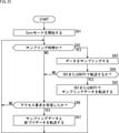
- FIG. 20 is a flowchart illustrating a communication process of the I3C master 21 that communicates by a conventional communication method.
- step S61 the I3C master 21 starts communication with the I3C slave 22 in Sync mode.
- step S62 the I3C master 21 determines whether or not sampling data transfer is necessary, and waits for processing until it is determined that sampling data transfer is necessary. Then, when the I3C master 21 determines that sampling data transfer is necessary, the process proceeds to step S63.
- step S63 the I3C master 21 determines whether or not the sampling data is received by IBI or MIPI.
- step S63 determines in step S63 that the sampling data is received by either IBI or MIPI. If the I3C master 21 determines in step S63 that the sampling data is received by either IBI or MIPI, the process proceeds to step S64. In step S64, after the I3C master 21 receives the sampling data in IBI or MIPI, the process returns to step S62, and the same process is repeated thereafter.
- step S63 determines in step S63 that the sampling data is not received in either IBI or MIPI, the process proceeds to step S65.
- step S65 the I3C master 21 determines whether or not sampling data is necessary, and if it is determined that sampling data is not necessary, the process returns to step S62, and the same process is repeated thereafter.
- step S65 determines in step S65 that sampling data is necessary
- the process proceeds to step S66.
- step S66 the I3C master 21 executes an access requesting the I3C slave 22 to read the sampling data, and receives the sampling data in response to the access. After that, the process returns to step S62, and the same process is repeated thereafter.
- FIG. 21 is a flowchart illustrating the communication process of the I3C slave 22 that communicates by the conventional communication method.
- step S71 the I3C slave 22 starts communication with the I3C master 21 in Sync mode.
- step S72 the I3C slave 22 determines whether or not the sampling time has been reached, and if it is determined that the sampling time has been reached, the process proceeds to step S73.
- step S73 the I3C slave 22 samples the data and generates the sampling data.
- step S74 the I3C slave 22 determines whether or not to transmit the sampling data by IBI or MIPI.
- step S74 determines in step S74 that the sampling data is transmitted by either IBI or MIPI. If the I3C slave 22 determines in step S74 that the sampling data is transmitted by either IBI or MIPI, the process proceeds to step S75. In step S75, the I3C slave 22 transfers the sampling data by IBI or MIPI, and then the process returns to step S72, and the same process is repeated thereafter.
- step S72 if it is determined in step S72 that the sampling time has not been reached, or if it is determined in step S74 that the sampling data is not transmitted in either IBI or MIPI, the process proceeds to step S76.
- step S76 the I3C slave 22 determines whether or not an access request requesting reading of sampling data has been received, and if it determines that the access request has not been received, the process returns to step S72, and so on. Process is repeated.
- step S76 if it is determined in step S76 that the I3C slave 22 has received an access request requesting reading of sampling data, the process proceeds to step S77.
- step S77 the I3C slave 22 transfers sampling data in response to an access request from the I3C master 21. After that, the process returns to step S72, and the same process is repeated thereafter.
- FIG. 22 is a flowchart illustrating the communication process of the I3C master 21 that communicates by the communication method to which the present technology is applied.
- steps S81 to S83 the same processing as in steps S61 to S63 of FIG. 20 is performed, and when the I3C master 21 determines in step S83 that the sampling data is received by either IBI or MIPI, the processing is performed in step S84. Proceed to.
- step S84 the I3C master 21 receives the sampling data and the association data by IBI or MIPI, confirms the association data in step S85, and then the process returns to step S82, and the same process is repeated thereafter. Will be done.
- step S86 the same processing as in step S65 of FIG. 20 is performed.
- step S87 the I3C master 21 executes an access requesting the I3C slave 22 to read the sampling data, and receives the sampling data and the associated data according to the access.
- step S88 after the I3C master 21 confirms the associated data, the process returns to step S82, and the same process is repeated thereafter.
- FIG. 23 is a flowchart illustrating the communication process of the I3C slave 22 that communicates by the communication method to which the present technology is applied.
- steps S91 to S94 the same processing as in steps S71 to S74 of FIG. 21 is performed.
- step S95 the I3C slave 22 transfers the sampling data and the associated data by IBI or MIPI, and then the process returns to step S92, and the same process is repeated thereafter.
- step S96 the same processing as in step S76 of FIG. 21 is performed.
- step S97 the I3C slave 22 transfers the sampling data and the associated data in response to the access request from the I3C master 21. After that, the process returns to step S92, and the same process is repeated thereafter.
- FIG. 24 is a block diagram showing a configuration example of the application processor 11 and the sensor device 12.
- the sensor device 12 includes a pixel 41, an output format selection unit 42, a CSI-2 transmission unit 43, a combo physical layer 44, an IBI protocol control unit 45, an I2C / I3C slave 46, a CCI slave 47, and a register. It is configured to include 48, a time synchronization counter 49, and an association data generation unit 51. Further, the association data generation unit 51 has an increment circuit 52.
- the application processor 11 includes a combo physical layer 61, a CSI-2 receiving unit 62, a sensor fusion unit 63, a linked data processing unit 64, a time synchronization counter 65, a CCI master 66, an I2C / I3C master 67, a RAM 58, and a processor 59. Be prepared to be configured.
- FIG. 25 is a circuit diagram showing a detailed configuration example of the associated data generation unit 51.
- the increment circuit 52 included in the associating data generation unit 51 includes adders 81-1 and 81-2, selection units 82-1 and 82-2, and selection units 83-1 and 83-2. And with latches 84-1 and 84-2.
- FIG. 26 is a block diagram showing a configuration example of the application processor 11 and the sensor device 12 that support both the Async mode and the Sync mode.
- the sensor device 12 includes a pixel 41, an output format selection unit 42, a CSI-2 transmission unit 43, a combo physical layer 44, an IBI protocol control unit 45, an I2C / I3C slave 46, a CCI slave 47, and a register. It includes 48, a time synchronization counter 49, an event detection unit 50, and an association data generation unit 51. Further, the associating data generation unit 51 has an increment circuit 52a for Async mode and an increment circuit 52s for Sync mode.
- the application processor 11 includes a combo physical layer 61, a CSI-2 receiving unit 62, a sensor fusion unit 63, a linked data processing unit 64, a time synchronization counter 65, a CCI master 66, an I2C / I3C master 67, a RAM 58, and a processor 59. Be prepared to be configured.
- FIG. 27 is a circuit diagram showing a detailed configuration example of the sync mode increment circuit 52s.
- the sync mode increment circuit 52s includes adders 81-1 and 81-2, selection units 82-1 and 82-2, selection units 83-1 and 83-2, and latch 84-1. And 84-2 are configured.
- FIG. 28 is a circuit diagram showing a detailed configuration example of the increment circuit 52a for Async mode.
- the increment circuit 52a for Async mode includes adders 81-1 and 81-2, selection units 82-1 and 82-2, selection units 83-1 and 83-2, and latch 84-1. And 84-2 are configured.
- FIG. 29 is a block diagram showing an example of hardware configuration of a computer that executes the above-mentioned series of processes programmatically.
- a CPU Central Processing Unit
- ROM Read Only Memory
- RAM Random Access Memory
- EEPROM Electrically Erasable and Programmable Read Only Memory
- the CPU 101 loads the programs stored in the ROM 102 and the EEPROM 104 into the RAM 103 via the bus 105 and executes them, thereby performing the above-mentioned series of processes. Further, the program executed by the computer (CPU 101) can be written in advance in the ROM 102, or can be installed or updated in the EEPROM 104 from the outside via the input / output interface 106.
- the processes performed by the computer according to the program do not necessarily have to be performed in chronological order in the order described as the flowchart. That is, the processing performed by the computer according to the program includes processing executed in parallel or individually (for example, processing by parallel processing or processing by an object).
- the program may be processed by one computer (processor) or may be distributed processed by a plurality of computers. Further, the program may be transferred to a distant computer and executed.
- the system means a set of a plurality of components (devices, modules (parts), etc.), and it does not matter whether all the components are in the same housing. Therefore, a plurality of devices housed in separate housings and connected via a network, and a device in which a plurality of modules are housed in one housing are both systems. ..
- the configuration described as one device (or processing unit) may be divided and configured as a plurality of devices (or processing units).
- the configurations described above as a plurality of devices (or processing units) may be collectively configured as one device (or processing unit).
- a configuration other than the above may be added to the configuration of each device (or each processing unit).
- a part of the configuration of one device (or processing unit) may be included in the configuration of another device (or other processing unit). ..
- this technology can have a cloud computing configuration in which one function is shared by a plurality of devices via a network and processed jointly.
- the above-mentioned program can be executed in any device.
- the device may have necessary functions (functional blocks, etc.) so that necessary information can be obtained.
- each step described in the above flowchart can be executed by one device or can be shared and executed by a plurality of devices.
- the plurality of processes included in the one step can be executed by one device or shared by a plurality of devices.
- a plurality of processes included in one step can be executed as processes of a plurality of steps.
- the processes described as a plurality of steps can be collectively executed as one step.
- the processing of the steps for describing the program may be executed in chronological order in the order described in the present specification, or may be called in parallel or called. It may be executed individually at the required timing such as when. That is, as long as there is no contradiction, the processes of each step may be executed in an order different from the above-mentioned order. Further, the processing of the step for describing this program may be executed in parallel with the processing of another program, or may be executed in combination with the processing of another program.
- the present technology can also have the following configurations.
- a linking data generation unit that generates linking data that links the timing of generating sampling data to the sampling data
- a communication device including a transmission unit that adds the linked data to the sampling data and transmits the data to another communication device via a bus.
- It is further equipped with a time information generator that generates time information indicating the time of occurrence of the event for which the sampling data is to be sampled.
- the linking data is the communication device according to (1) above, which links the time information and the sampling data.
- the transmitter is The time information and the associated data are transmitted by data transfer for which an interrupt request is made to the other communication device.
- the communication device which transmits the sampling data and the association data in response to an access request from the other communication device.
- the transmission unit transmits the time information and the associated data by using the IBI (In Band Interrupts) protocol of I3C (Improved Inter Integrated Circuit).
- the transmission unit transmits the sampling data and the association data by using the IBI protocol or the MIPI (Mobile Industry Processor Interface) protocol.
- the timing at which the generation of the sampling data is started coincides with the timing at which the generation of the time information indicating the time when the generation of the sampling data is started is started, and the sampling data and the time information are generated in parallel.
- the communication device according to any one of (1) to (5).
- the association data is described in any one of (1) to (6) above, which associates the sampling data generated by sampling performed at periodic timing with the sampling timing at which the sampling data is sampled.
- Communication device (8)
- the communication device To generate linked data that links the timing of generating sampling data to the sampling data, A communication method including adding the linked data to the sampling data and transmitting the linked data to another communication device via a bus.
- a program for executing communication processing including adding the associated data to the sampling data and transmitting it to another communication device via a bus.
Landscapes
- Engineering & Computer Science (AREA)
- Theoretical Computer Science (AREA)
- Physics & Mathematics (AREA)
- General Engineering & Computer Science (AREA)
- General Physics & Mathematics (AREA)
- Communication Control (AREA)
- Information Transfer Systems (AREA)
Abstract
本開示は、サンプリングのタイミングに関する通信機能の向上を図ることができるようにする通信装置、通信方法、およびプログラムに関する。 サンプリングデータを生成したタイミングをサンプリングデータに紐づける紐づけデータを生成する紐づけデータ生成部と、紐づけデータをサンプリングデータに付加し、バスを介して他の通信装置に送信する送信部とを備える。さらに、サンプリングデータのサンプリングを行うことになったイベントの発生時刻を示す時刻情報を生成する時刻情報生成部を備え、紐づけデータは、時刻情報とサンプリングデータとを紐づける。本技術は、例えば、I3Cの規格に準拠して通信を行う通信システムに適用できる。
Description
本開示は、通信装置、通信方法、およびプログラムに関し、特に、サンプリングのタイミングに関する通信機能の向上を図ることができるようにした通信装置、通信方法、およびプログラムに関する。
従来、各種のデバイスにおけるレジスタを制御するためのバスIF(Interface)としてI2C(Inter-Integrated Circuit)規格が広く採用されている。近年、I2Cの高速化・多機能化を実現することが求められており、次世代の規格としてMIPI(Mobile Industry Processor Interface) AllianceにてI3C(Improved Inter Integrated Circuit)の規定が策定され、その改定が進められている。
例えば、I2CおよびI3Cは、バスIFを介した通信の主導権を有するマスタによる制御に従って、バスIFに接続されているスレーブと通信を行うことができるように構成される。また、I3Cは、バスIFに接続されているスレーブが割り込み要求できるようにするIBI(In Band Interrupts)機能や、データの送信タイミングをコントロールするタイミングコントロール機能を備えている。
例えば、特許文献1には、マルチシンボルのための同期方法として、シリアルバス上で同期コードを送信し、その同期コードに応答して同期を確立するシステムが開示されている。
ところで、従来のI3Cバスの構成では、例えば、サンプリングデータと、そのサンプリングデータが生成されたタイミングとの関係が不明確になることがあった。そのため、サンプリングデータと、そのサンプリングデータが生成されたタイミングとの関係が明確になるように、サンプリングのタイミングに関する通信機能を向上させることが求めされている。
本開示は、このような状況に鑑みてなされたものであり、サンプリングのタイミングに関する通信機能の向上を図ることができるようにするものである。
本開示の一側面の通信装置は、サンプリングデータを生成したタイミングを前記サンプリングデータに紐づける紐づけデータを生成する紐づけデータ生成部と、前記紐づけデータを前記サンプリングデータに付加し、バスを介して他の通信装置に送信する送信部とを備える。
本開示の一側面の通信方法またはプログラムは、サンプリングデータを生成したタイミングを前記サンプリングデータに紐づける紐づけデータを生成することと、前記紐づけデータを前記サンプリングデータに付加し、バスを介して他の通信装置に送信することとを含む。
本開示の一側面においては、サンプリングデータを生成したタイミングをサンプリングデータに紐づける紐づけデータが生成され、その紐づけデータがサンプリングデータに付加され、バスを介して他の通信装置に送信される。
以下、本技術を適用した具体的な実施の形態について、図面を参照しながら詳細に説明する。
<通信システムの構成例>
図1は、本技術を適用した通信システムの一実施の形態の構成例を示すブロック図である。
図1は、本技術を適用した通信システムの一実施の形態の構成例を示すブロック図である。
図1に示す通信システムは、アプリケーションプロセッサ11およびセンサデバイス12が、シリアルデータSDAを伝送する信号線と、シリアルクロックSCLを伝送する信号線との2本の信号線からなるI3Cバスを介して接続され、I3Cの規格に準拠して通信を行う。例えば、アプリケーションプロセッサ11はI3Cマスタ21を備えており、センサデバイス12はI3Cスレーブ22およびセンサ23を備えている。
図1のAには、1台のI3Cマスタ21に対して1台のI3Cスレーブ22が接続された構成例の通信システムが示されている。図1のBには、1台のI3Cマスタ21に対して2台のI3Cスレーブ22-1および22-2が接続された構成例の通信システムが示されている。
I3Cマスタ21は、I3Cバスにおける通信の主導権を有しており、例えば、I3Cスレーブ22に対して読出し要求や書込み要求などのアクセス要求を行って、I3Cスレーブ22との通信を制御する。
I3Cスレーブ22は、I3Cマスタ21による通信の制御に従属して、I3Cバスを介した通信を行うことができる。なお、I3Cスレーブ22-1および22-2は、それぞれ同様の構成となっている。
センサ23には、例えば、イメージセンサやジャイロセンサなど各種のセンサを用いることができ、所定のサンプリング周期で、または、I3Cスレーブ22からの要求に応じて、センシング結果として得られるデータをI3Cスレーブ22に供給することができる。
このような構成の通信システムにおいて、I3Cマスタ21およびI3Cスレーブ22は、以下で説明するような本技術を適用した通信方法で通信することができる。
例えば、I3Cスレーブ22は、サンプリングデータを生成したタイミングをサンプリングデータに紐づける紐づけデータを生成して、その紐づけデータをサンプリングデータに付加し、I3Cバスを介してI3Cマスタ21に送信する。さらに、I3Cスレーブ22は、サンプリングデータのサンプリングを行うことになったイベントの発生時刻を示す時刻情報を生成し、紐づけデータによって、時刻情報とサンプリングデータとを紐づけることができる。
<第1の実施の形態>
図2乃至図14は、本技術を適用した通信方法の第1の実施の形態について説明する図である。
図2乃至図14は、本技術を適用した通信方法の第1の実施の形態について説明する図である。
図2乃至図6を参照して、読み出しプロトコルを使用してデータ転送を行う処理例について、従来の通信方法と、本技術を適用した通信方法とを比較して説明する。ここでは、図1のAに示したように、1台のI3Cマスタ21に対して1台のI3Cスレーブ22が接続された構成の通信システムにおける通信方法について説明する。
図2に示すように、従来の通信方法では、I3Cマスタ21およびI3Cスレーブ22がAsyncモードで通信を行っているときに、イベント1が発生すると、I3Cスレーブ22は、イベント1が発生したタイミングの時刻を示す時刻情報1を生成する。そして、I3Cスレーブ22は、IBIプロトコルによって、MDBデータおよび時刻情報1をI3Cマスタ21に送信する。これに応じ、I3Cマスタ21は、読み出しプロトコルによって、リードデータを要求するアクセス要求をI3Cスレーブ22に送信する。そして、I3Cスレーブ22は、アクセス要求に応じてACK応答を行って、イベント1のデータをサンプリングしたサンプリングデータをI3Cマスタ21に送信する。
その後、同様に、イベント2が発生すると、I3Cスレーブ22は、イベント2が発生したタイミングの時刻を示す時刻情報2を生成する。そして、I3Cスレーブ22は、IBIプロトコルによって、MDBデータおよび時刻情報2をI3Cマスタ21に送信する。これに応じ、I3Cマスタ21は、読み出しプロトコルによって、リードデータを要求するアクセス要求をI3Cスレーブ22に送信する。そして、I3Cスレーブ22は、アクセス要求に応じてACK応答を行って、イベント2のデータをサンプリングしたサンプリングデータをI3Cマスタ21に送信する。
このような従来の通信方法では、イベントが多重的に発生した場合には、サンプリングデータをサンプリングしたサンプリングタイミングが不明になることがある。
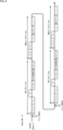
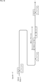
図3は、イベントが多重的に発生した場合に、サンプリングデータをサンプリングしたサンプリングタイミングが不明になることについて説明する図である。
即ち、図3に示すように、イベント1の発生に応じて時刻情報1を送信するIBIプロトコルが終了した直後に、イベント2が発生した場合、イベント1のサンプリングデータを送信する読み出しプロトコルが行われることなく、イベント2の発生に応じて時刻情報2を送信するIBIプロトコルが行われることがある。このとき、イベント2の発生に応じて時刻情報2を送信するIBIプロトコルが行われた後に、読み出しプロトコルが行われても、この読み出しプロトコルで送信されるサンプリングデータのサンプリングタイミングが不明となってしまう。即ち、この読み出しプロトコルで送信されるサンプリングデータは、イベント1およびイベント2のどちらのサンプリングデータであるかを特定することができない。
そこで、本技術を適用した通信方法では、時刻情報とサンプリングデータとを紐づける紐づけデータを利用して、イベントが多重的に発生した場合であっても、サンプリングデータのサンプリングタイミングが不明となってしまうことを回避することができる。
図4に示すように、本技術を適用した通信方法では、I3Cマスタ21およびI3Cスレーブ22がAsyncモードで通信を行っているときに、イベント1が発生すると、I3Cスレーブ22は、イベント1が発生したタイミングの時刻を示す時刻情報1を生成する。そして、I3Cスレーブ22は、IBIプロトコルによって、MDBデータおよび時刻情報1を送信するのに加えて、イベント1のサンプリングデータに時刻情報1を紐づけるための紐づけデータ1をI3Cマスタ21に送信する。これに応じ、I3Cマスタ21は、読み出しプロトコルによって、リードデータを要求するアクセス要求をI3Cスレーブ22に送信する。そして、I3Cスレーブ22は、アクセス要求に応じてACK応答を行って、紐づけデータ1に続けてイベント1のサンプリングデータをI3Cマスタ21に送信する。
その後、同様に、イベント2が発生すると、I3Cスレーブ22は、イベント2が発生したタイミングの時刻を示す時刻情報2を生成する。そして、I3Cスレーブ22は、IBIプロトコルによって、MDBデータおよび時刻情報2を送信するのに加えて、イベント2のサンプリングデータに時刻情報2を紐づけるための紐づけデータ2をI3Cマスタ21に送信する。これに応じ、I3Cマスタ21は、読み出しプロトコルによって、リードデータを要求するアクセス要求をI3Cスレーブ22に送信する。そして、I3Cスレーブ22は、アクセス要求に応じてACK応答を行って、紐づけデータ2に続けてイベント2のサンプリングデータをI3Cマスタ21に送信する。
このように、本技術を適用した通信方法では、紐づけデータを利用することで、イベントが多重的に発生した場合でも、サンプリングデータをサンプリングしたサンプリングタイミングが不明となることを回避することができる。
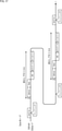
図5は、イベントが多重的に発生した場合でも、サンプリングデータをサンプリングしたサンプリングタイミングを特定することができることについて説明する図である。
即ち、図5に示すように、イベント1の発生に応じて時刻情報1を送信するIBIプロトコルが終了した直後に、イベント2が発生した場合、続けて、イベント2の発生に応じて時刻情報2を送信するIBIプロトコルが行われる。このとき、時刻情報1に加えて紐づけデータ1が送信され、時刻情報2に加えて紐づけデータ2が送信される。その後、読み出しプロトコルが行われて、紐づけデータ1に続けてイベント1のサンプリングデータが送信され、さらに、読み出しプロトコルが行われて、紐づけデータ2に続けてイベント2のサンプリングデータが送信される。
このように、イベントが多重的に発生した場合でも、I3Cマスタ21は、紐づけデータ1に基づいて、イベント1のサンプリングデータと時刻情報1とを紐づけることができるとともに、紐づけデータ2に基づいて、イベント2のサンプリングデータと時刻情報2とを紐づけることができる。従って、I3Cマスタ21は、イベント1のサンプリングデータのサンプリングタイミングを時刻情報1に従って認識し、イベント2のサンプリングデータのサンプリングタイミングを時刻情報2に従って認識することができる。
このため、I3Cマスタ21は、複数回のサンプリングデータのサンプリングタイミングを個々に認識することができるので、例えば、複数回のサンプリングデータをバス帯域に余裕のあるタイミングで纏めて送信することができる。即ち、複数回のサンプリングデータをバス帯域に余裕のあるタイミングで纏めて送信しても、I3Cマスタ21は、個々のサンプリングデータのサンプリングタイミングが不明となることを回避することができる。
ここで、図6には、サンプリングデータを識別できるようなID値を用いた紐づけデータの構成例が示されている。
例えば、図6に示すように、紐づけデータを1バイトと定義し、最上位の1ビットはAsync Mode制御でサンプリングしたこと、または、Sync Mode制御でサンプリングしたことを示し、残りのビットはイベントが発生するごとにインクリメントする。
ここで、図7および図8を参照して、複数のI3Cスレーブ22で同じイベントを検出する処理例について、従来の通信方法と、本技術を適用した通信方法とを比較して説明する。ここでは、図1のBに示したように、1台のI3Cマスタ21に対して2台のI3Cスレーブ22-1および22-2が接続された構成の通信システムにおける通信方法について説明する。また、図7および図8を参照して説明する処理例では、例えば、I3Cスレーブ22-1は、イメージセンサのようにサンプリングデータ生成時間が長く、I3Cスレーブ22-2は、ジャイロセンサのようにサンプリングデータ生成時間が短いものとする。
図7に示すように、従来の通信方法では、I3Cスレーブ22-1は、イベントの発生に応じてサンプリングデータ生成期間を開始し、サンプリングデータ生成期間、時刻情報生成期間、およびIBIプロトコル送信期間を連続して行う。従って、I3Cスレーブ22-1は、サンプリングデータ生成期間においてサンプリングデータを生成し終わった時刻を、そのサンプリングデータの生成を開始した時刻を示す時刻情報の生成を開始する時刻情報生成タイミングとして、時刻情報生成期間において時刻情報を生成する。その後、I3Cスレーブ22-1は、IBIプロトコル送信期間においてIBIプロトコルでサンプリングデータおよび時刻情報を送信する。
同様に、I3Cスレーブ22-2は、イベントの発生に応じてサンプリングデータ生成期間を開始し、サンプリングデータ生成期間、時刻情報生成期間、およびIBIプロトコル送信期間を連続して行う。従って、I3Cスレーブ22-2は、サンプリングデータ生成期間においてサンプリングデータを生成し終わった時刻を、時刻情報を生成する時刻情報生成タイミングとして、時刻情報生成期間において時刻情報を生成する。その後、I3Cスレーブ22-1は、IBIプロトコル送信期間においてIBIプロトコルでサンプリングデータおよび時刻情報を送信する。
このような従来の通信方法では、I3Cスレーブ22-1および22-2が同一のイベントのサンプリングデータを生成しているにも関わらず、それぞれの時刻情報生成タイミングが異なることより、IBIプロトコルで送信される時刻情報が異なるものとなる。そのため、I3Cマスタ21は、それらのサンプリングデータが同じイベントを検出したものであると認識することができない恐れがある。
そこで、図8に示すように、本技術を適用した通信方法では、イベントの発生に応じて、サンプリングデータ生成期間を開始するタイミングと、時刻情報生成期間を開始するタイミングとを一致させ、サンプリングデータ生成期間および時刻情報生成期間を並列して行う。そして、それぞれのサンプリングデータ生成期間が終了すると、IBIプロトコル送信期間が行われてサンプリングデータおよび時刻情報が送信される。
これにより、I3Cスレーブ22-1および22-2は、同一の時刻情報生成タイミングで時刻情報を生成することができ、IBIプロトコルで送信される時刻情報が同じものとなる。従って、I3Cマスタ21は、それらのサンプリングデータが同じイベントを検出したものであると認識することができる。
<通信処理>
図9乃至図12を参照して、第1の実施の形態における通信処理について説明する。
図9乃至図12を参照して、第1の実施の形態における通信処理について説明する。
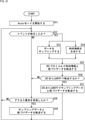
図9は、従来の通信方法で通信を行うI3Cマスタ21の通信処理を説明するフローチャートである。
ステップS11において、I3Cマスタ21は、AsyncモードでI3Cスレーブ22との通信を開始する。
ステップS12において、I3Cマスタ21は、I3Cスレーブ22から転送されてくるIBIを受信したか否かを判定し、IBIを受信したと判定するまで処理を待機する。そして、I3Cマスタ21は、IBIを受信したと判定した場合、処理はステップS13に進む。
ステップS13において、I3Cマスタ21は、I3Cスレーブ22からIBIで転送されてくる時刻情報を取得する。ステップS14において、I3Cマスタ21は、ステップS13で取得した時刻情報に従って、イベント発生時刻を生成する。
ステップS15において、I3Cマスタ21は、サンプリングデータをIBIまたはMIPIで受信するか否かを判定する。
ステップS15において、I3Cマスタ21が、サンプリングデータをIBIまたはMIPIのいずれかで受信すると判定した場合、処理はステップS16に進む。ステップS16において、I3Cマスタ21は、IBIまたはMIPIでサンプリングデータを受信した後、処理はステップS12に戻り、以下、同様の処理が繰り返して行われる。
一方、ステップS15において、I3Cマスタ21が、サンプリングデータをIBIまたはMIPIのどちらにおいても受信しないと判定した場合、処理はステップS17に進む。
ステップS17において、I3Cマスタ21は、サンプリングデータが必要か否かを判定し、サンプリングデータが必要でないと判定した場合、処理はステップS12に戻り、以下、同様の処理が繰り返して行われる。
一方、ステップS17において、I3Cマスタ21が、サンプリングデータが必要であると判定した場合、処理はステップS18に進む。ステップS18において、I3Cマスタ21は、I3Cスレーブ22に対してサンプリングデータの読み出しを要求するアクセスを実行し、そのアクセスに応じてサンプリングデータを受信する。その後、処理はステップS12に戻り、以下、同様の処理が繰り返して行われる。
図10は、従来の通信方法で通信を行うI3Cスレーブ22の通信処理を説明するフローチャートである。
ステップS21において、I3Cスレーブ22は、AsyncモードでI3Cマスタ21との通信を開始する。
ステップS22において、I3Cスレーブ22は、イベントが発生したか否かを判定し、イベントが発生したと判定した場合、処理はステップS23に進む。
ステップS23において、I3Cスレーブ22は、イベントのデータをサンプリングしてサンプリングデータを生成する。その後、ステップS24において、I3Cスレーブ22は、時刻情報生成タイミング(図7参照)に従って時刻情報を生成する。ステップS25において、I3Cスレーブ22は、IBIプロトコルで時刻情報をI3Cマスタ21へ転送する。
ステップS26において、I3Cスレーブ22は、サンプリングデータをIBIまたはMIPIで転送するか否かを判定する。
ステップS26において、I3Cスレーブ22が、サンプリングデータをIBIまたはMIPIのいずれかで転送すると判定した場合、処理はステップS27に進む。ステップS27において、I3Cスレーブ22は、IBIまたはMIPIでサンプリングデータを転送した後、処理はステップS22に戻り、以下、同様の処理が繰り返して行われる。
一方、ステップS22において、イベントが発生していないと判定された場合、または、ステップS26において、サンプリングデータをIBIまたはMIPIのどちらにおいても転送しないと判定された場合、処理はステップS28に進む。
ステップS28において、I3Cスレーブ22は、サンプリングデータの読み出しを要求するアクセス要求を受信したか否かを判定し、アクセス要求を受信してないと判定した場合、処理はステップS22に戻り、以下、同様の処理が繰り返して行われる。
一方、ステップS28において、I3Cスレーブ22が、サンプリングデータの読み出しを要求するアクセス要求を受信したと判定した場合、処理はステップS29に進む。ステップS29において、I3Cスレーブ22は、I3Cマスタ21からのアクセス要求に応じてサンプリングデータを転送する。その後、処理はステップS22に戻り、以下、同様の処理が繰り返して行われる。
図11は、本技術を適用した通信方法で通信を行うI3Cマスタ21の通信処理を説明するフローチャートである。
ステップS31およびS32において、図9のステップS11およびS12と同様の処理が行われる。
ステップS33において、I3Cマスタ21は、I3Cスレーブ22からIBIで転送されてくる時刻情報と紐づけデータを取得する。
ステップS34およびS35において、図9のステップS14およびS15と同様の処理が行われる。
ステップS36において、I3Cマスタ21は、IBIまたはMIPIでサンプリングデータと紐づけデータを受信する。ステップS37において、I3Cマスタ21は、紐づけデータを確認した後、処理はステップS32に戻り、以下、同様の処理が繰り返して行われる。
ステップS38において、図9のステップS17と同様の処理が行われる。
ステップS39において、I3Cマスタ21は、I3Cスレーブ22に対してサンプリングデータの読み出しを要求するアクセスを実行し、そのアクセスに応じてサンプリングデータと紐づけデータを受信する。ステップS40において、I3Cマスタ21は、紐づけデータを確認した後、処理はステップS32に戻り、以下、同様の処理が繰り返して行われる。
図12は、本技術を適用した通信方法で通信を行うI3Cスレーブ22の通信処理を説明するフローチャートである。
ステップS51およびS52において、図10のステップS21およびS22と同様の処理が行われ、ステップS52において、イベントが発生したと判定した場合、処理はステップS53およびS54に並列的に進む。
ステップS53において、I3Cスレーブ22は、イベントのデータをサンプリングしてサンプリングデータを生成するのと並行して、ステップS54において、I3Cスレーブ22は、時刻情報生成タイミング(図8参照)に従って時刻情報を生成する。さらに、ステップS54において、I3Cスレーブ22は、生成した時刻情報をサンプリングデータに紐づけるための紐づけデータを生成する。
ステップS55において、I3Cスレーブ22は、IBIプロトコルで時刻情報と紐づけデータをI3Cマスタ21へ転送する。
ステップS56において、図10のステップS26と同様の処理が行われる。
ステップS57において、I3Cスレーブ22は、IBIまたはMIPIでサンプリングデータと紐づけデータを転送した後、処理はステップS52に戻り、以下、同様の処理が繰り返して行われる。
ステップS58において、図10のステップS28と同様の処理が行われる。
ステップS59において、I3Cスレーブ22は、I3Cマスタ21からのアクセス要求に応じてサンプリングデータと紐づけデータを転送する。その後、処理はステップS52に戻り、以下、同様の処理が繰り返して行われる。
<アプリケーションプロセッサおよびセンサデバイスの構成例>
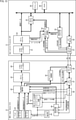
図13は、アプリケーションプロセッサ11およびセンサデバイス12の構成例を示すブロック図である。
図13は、アプリケーションプロセッサ11およびセンサデバイス12の構成例を示すブロック図である。
図13に示すように、センサデバイス12は、画素41、出力形式選択部42、CSI-2送信部43、コンボ物理層44、IBIプロトコル制御部45、I2C/I3Cスレーブ46、CCIスレーブ47、レジスタ48、時刻同期カウンタ49、イベント検出部50、および紐づけデータ生成部51を備えて構成される。また、紐づけデータ生成部51は、インクリメント回路52を有している。アプリケーションプロセッサ11は、コンボ物理層61、CSI-2受信部62、センサフュージョン部63、紐づけデータ処理部64、時刻同期カウンタ65、CCIマスタ66、I2C/I3Cマスタ67、RAM58、およびプロセッサ59を備えて構成される。
ここで、I2C/I3Cスレーブ46は、図1のI3Cスレーブ22に対応し、I2C/I3Cマスタ67は、図1のI3Cマスタ21に対応する。また、図13に示す構成例では、センサデバイス12は、CMOSイメージセンサであり、図1のセンサ23が、画素41を有する構成となっている。
画素41は、撮像を行って画像データを生成し、低解像度RAWデータまたは高解像度RAWデータを出力形式選択部42に供給する。出力形式選択部42は、レジスタ48に設定されている設定値に応じた出力形式選択信号に従って、アプリケーションプロセッサ11に転送する画像データを生成し、CSI-2送信部43、IBIプロトコル制御部45、またはCCIスレーブ47に供給する。CSI-2送信部43は、CSI-2プロトコルに従って画像データを送信するための処理を行って、画像データをコンボ物理層44に供給する。コンボ物理層44は、MIPIによる通信を制御し、C-PHYまたはD-PHYで画像データをアプリケーションプロセッサ11に送信する。
IBIプロトコル制御部45は、出力形式選択部42から供給される画像データからIBI転送用データを生成し、I2C/I3Cスレーブ46に供給する。I2C/I3Cスレーブ46は、I2C/I3Cプロトコルを制御して、画像データに紐づけデータを付加し、I2C/I3Cバスを介してアプリケーションプロセッサ11に送信する。CCIスレーブ47は、CCIプロトコルを制御し、例えば、レジスタ48に設定値などを書き込む。
時刻同期カウンタ49は、Asyncモード時の基準時刻となるカウンタブロックであり、イベント検出部50からイベント検出信号が供給されたタイミングのカウント値(画素41が画像データの生成を行うことになったイベントの発生時刻を示す時刻情報)を、イベント時刻信号として出力形式選択部42に供給する。イベント検出部50は、イベントを検出すると、画素41、時刻同期カウンタ49、および紐づけデータ生成部51にイベント検出信号を供給する。紐づけデータ生成部51は、レジスタ48の動作モード信号に従ったモードに応じた紐づけデータ(画素41が画像データを生成したタイミングを示す時刻情報を、その画像データに紐づけるデータ)を生成して、出力形式選択部42に供給する。
コンボ物理層61は、MIPIによる通信を制御し、コンボ物理層44からC-PHYまたはD-PHYで送信されてくる画像データを取得して、CSI-2受信部62に供給する。CSI-2受信部62は、CSI-2プロトコルに従って画像データを受信し、センサフュージョン部63に供給する。センサフュージョン部63は、CSI-2受信部62から供給される画像と、紐づけデータ処理部64から供給される撮像時刻との対応付けを行う。
紐づけデータ処理部64は、紐づけデータを確認して、Syncモード時は紐づけデータと時刻情報を対応させ、Asyncモード時には紐づけデータとイベント時刻情報とを対応させて撮像時刻を求める。時刻同期カウンタ65は、Syncモード時の基準時刻となるカウンタブロックであり、時刻情報を紐づけデータ処理部64に供給する。CCIマスタ66は、CCIプロトコルを制御し、I2C/I3Cマスタ67は、I2C/I3Cプロトコルを制御する。
RAM58は、画像データなど各種のデータを格納し、プロセッサ59は、プログラムに従ってMIPIおよびI3C通信を制御する。
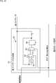
図14は、紐づけデータ生成部51の詳細な構成例を示す回路図である。
図14に示すように、紐づけデータ生成部51が有するインクリメント回路52は、加算器81、選択部82、選択部83、およびラッチ84を備えて構成される。
<第2の実施の形態>
図15乃至図28は、本技術を適用した通信方法の第2の実施の形態について説明する図である。
図15乃至図28は、本技術を適用した通信方法の第2の実施の形態について説明する図である。
図15乃至図19を参照して、読み出しプロトコルを使用してデータ転送を行う処理例について、従来の通信方法と、本技術を適用した通信方法とを比較して説明する。ここでは、図1のAに示したように、1台のI3Cマスタ21に対して1台のI3Cスレーブ22が接続された構成の通信システムにおける通信方法について説明する。
図15に示すように、従来の通信方法では、I3Cマスタ21およびI3Cスレーブ22がSyncモードで通信を行っているときに、I3Cマスタ21は、Sync Tickを発行し、I3Cスレーブ22は、Sync Tickに従ってサンプリング1を行う。その後、I3Cマスタ21は、読み出しプロトコルによって、リードデータを要求するアクセス要求をI3Cスレーブ22に送信する。そして、I3Cスレーブ22は、アクセス要求に応じてACK応答を行って、サンプリング1のデータをサンプリングしたサンプリングデータをI3Cマスタ21に送信する。
さらに、I3Cスレーブ22は、Sync Tickから所定期間が経過したタイミングでサンプリング2を行う。その後、I3Cマスタ21は、読み出しプロトコルによって、リードデータを要求するアクセス要求をI3Cスレーブ22に送信する。そして、I3Cスレーブ22は、アクセス要求に応じてACK応答を行って、サンプリング2のデータをサンプリングしたサンプリングデータをI3Cマスタ21に送信する。
このような従来の通信方法では、図16に示すように、サンプリング2を行うタイミングを超えたタイミングで、リードデータを要求するアクセス要求を行った場合には、サンプリングデータをサンプリングしたサンプリングタイミングが不明になることがある。即ち、この読み出しプロトコルで送信されるサンプリングデータは、サンプリング1およびサンプリング2のどちらのサンプリングデータであるかを特定することができない。
そこで、本技術を適用した通信方法では、サンプリングタイミングとサンプリングデータとを紐づける紐づけデータを利用して、サンプリングデータのサンプリングタイミングが不明となってしまうことを回避することができる。
図17に示すように、本技術を適用した通信方法では、I3Cマスタ21およびI3Cスレーブ22がSyncモードで通信を行っているときに、Sync Tickに従ってサンプリング1が行われると、I3Cスレーブ22は、サンプリング1のサンプリングタイミングを示す紐づけデータ1を生成する。そして、I3Cマスタ21は、読み出しプロトコルによって、リードデータを要求するアクセス要求をI3Cスレーブ22に送信する。そして、I3Cスレーブ22は、アクセス要求に応じてACK応答を行って、紐づけデータ1に続けてサンプリング1のサンプリングデータをI3Cマスタ21に送信する。
さらに、I3Cスレーブ22は、Sync Tickから所定期間が経過したタイミングでサンプリング2を行う。このとき、I3Cスレーブ22は、サンプリング2のサンプリングタイミングを示す紐づけデータ2を生成する。そして、I3Cマスタ21は、読み出しプロトコルによって、リードデータを要求するアクセス要求をI3Cスレーブ22に送信する。そして、I3Cスレーブ22は、アクセス要求に応じてACK応答を行って、紐づけデータ2に続けてサンプリング2のサンプリングデータをI3Cマスタ21に送信する。
このように、本技術を適用した通信方法では、周期的なタイミングで行われるサンプリングにより生成されるサンプリングデータと、そのサンプリングデータがサンプリングされたサンプリングタイミングとを紐づける紐づけデータを利用する。これにより、サンプリング2を行うタイミングを超えたタイミングで、リードデータを要求するアクセス要求があった場合でも、サンプリングデータ1および2をサンプリングしたサンプリングタイミングが不明となることを回避することができる。
図18は、サンプリング2を行うタイミングを超えたタイミングで、リードデータを要求するアクセス要求があった場合でも、サンプリングデータ1および2をサンプリングしたサンプリングタイミングを特定することができることについて説明する図である。
即ち、図18に示すように、Sync Tickに従ってサンプリング1が行われた後、アクセス要求なくSync Tickから所定期間が経過したタイミングでサンプリング2が行われたとする。この場合でも、I3Cスレーブ22は、アクセス要求に応じてACK応答を行って、紐づけデータ1に続けてサンプリング1のサンプリングデータをI3Cマスタ21に送信する。その後、I3Cスレーブ22は、アクセス要求に応じてACK応答を行って、紐づけデータ2に続けてサンプリング2のサンプリングデータをI3Cマスタ21に送信する。従って、I3Cマスタ21は、サンプリング1のサンプリングデータのサンプリングタイミングを紐づけデータ1に従って認識し、サンプリング2のサンプリングデータのサンプリングタイミングを紐づけデータ2に従って認識することができる。
このため、I3Cマスタ21は、複数回のサンプリングデータのサンプリングタイミングを個々に認識することができるので、例えば、複数回のサンプリングデータをバス帯域に余裕のあるタイミングで纏めて送信することができる。即ち、複数回のサンプリングデータをバス帯域に余裕のあるタイミングで纏めて送信しても、I3Cマスタ21は、個々のサンプリングデータのサンプリングタイミングが不明となることを回避することができる。
ここで、図19には、サンプリングデータを識別できるようなID値を用いた紐づけデータの構成例が示されている。
例えば、図19に示すように、最上位の1ビットはAsync Mode制御でサンプリングしたこと、または、Sync Mode制御でサンプリングしたことを示している。そして、図19は、上位3ビットは同期パルスごとにインクリメントし、下位4ビットはサンプリングごとにインクリメントする。そして、図19には、1バイトの値を紐づけデータとして定義した場合の動作例が記載されている。
<通信処理>
図20乃至図23を参照して、第2の実施の形態における通信処理について説明する。
図20乃至図23を参照して、第2の実施の形態における通信処理について説明する。
図20は、従来の通信方法で通信を行うI3Cマスタ21の通信処理を説明するフローチャートである。
ステップS61において、I3Cマスタ21は、SyncモードでI3Cスレーブ22との通信を開始する。
ステップS62において、I3Cマスタ21は、サンプリングデータ転送が必要であるか否かを判定し、サンプリングデータ転送が必要であると判定されるまで処理を待機する。そして、I3Cマスタ21は、サンプリングデータ転送が必要であると判定した場合、処理はステップS63に進む。
ステップS63において、I3Cマスタ21は、サンプリングデータをIBIまたはMIPIで受信するか否かを判定する。
ステップS63において、I3Cマスタ21が、サンプリングデータをIBIまたはMIPIのいずれかで受信すると判定した場合、処理はステップS64に進む。ステップS64において、I3Cマスタ21は、IBIまたはMIPIでサンプリングデータを受信した後、処理はステップS62に戻り、以下、同様の処理が繰り返して行われる。
一方、ステップS63において、I3Cマスタ21が、サンプリングデータをIBIまたはMIPIのどちらにおいても受信しないと判定した場合、処理はステップS65に進む。
ステップS65において、I3Cマスタ21は、サンプリングデータが必要か否かを判定し、サンプリングデータが必要でないと判定した場合、処理はステップS62に戻り、以下、同様の処理が繰り返して行われる。
一方、ステップS65において、I3Cマスタ21が、サンプリングデータが必要であると判定した場合、処理はステップS66に進む。ステップS66において、I3Cマスタ21は、I3Cスレーブ22に対してサンプリングデータの読み出しを要求するアクセスを実行し、そのアクセスに応じてサンプリングデータを受信する。その後、処理はステップS62に戻り、以下、同様の処理が繰り返して行われる。
図21は、従来の通信方法で通信を行うI3Cスレーブ22の通信処理を説明するフローチャートである。
ステップS71において、I3Cスレーブ22は、SyncモードでI3Cマスタ21との通信を開始する。
ステップS72において、I3Cスレーブ22は、サンプリング時間となったか否かを判定し、サンプリング時間となったと判定した場合、処理はステップS73に進む。
ステップS73において、I3Cスレーブ22は、データをサンプリングしてサンプリングデータを生成する。
ステップS74において、I3Cスレーブ22は、サンプリングデータをIBIまたはMIPIで送信するか否かを判定する。
ステップS74において、I3Cスレーブ22が、サンプリングデータをIBIまたはMIPIのいずれかで送信すると判定した場合、処理はステップS75に進む。ステップS75において、I3Cスレーブ22は、IBIまたはMIPIでサンプリングデータを転送した後、処理はステップS72に戻り、以下、同様の処理が繰り返して行われる。
一方、ステップS72において、サンプリング時間となっていないと判定された場合、または、ステップS74において、サンプリングデータをIBIまたはMIPIのどちらにおいても送信しないと判定された場合、処理はステップS76に進む。
ステップS76において、I3Cスレーブ22は、サンプリングデータの読み出しを要求するアクセス要求を受信したか否かを判定し、アクセス要求を受信してないと判定した場合、処理はステップS72に戻り、以下、同様の処理が繰り返して行われる。
一方、ステップS76において、I3Cスレーブ22が、サンプリングデータの読み出しを要求するアクセス要求を受信したと判定した場合、処理はステップS77に進む。ステップS77において、I3Cスレーブ22は、I3Cマスタ21からのアクセス要求に応じてサンプリングデータを転送する。その後、処理はステップS72に戻り、以下、同様の処理が繰り返して行われる。
図22は、本技術を適用した通信方法で通信を行うI3Cマスタ21の通信処理を説明するフローチャートである。
ステップS81乃至S83において、図20のステップS61乃至S63と同様の処理が行われ、ステップS83において、I3Cマスタ21が、サンプリングデータをIBIまたはMIPIのいずれかで受信すると判定した場合、処理はステップS84に進む。
ステップS84において、I3Cマスタ21は、IBIまたはMIPIでサンプリングデータと紐づけデータを受信し、その紐づけデータをステップS85において確認した後、処理はステップS82に戻り、以下、同様の処理が繰り返して行われる。
ステップS86において、図20のステップS65と同様の処理が行われる。
ステップS87において、I3Cマスタ21は、I3Cスレーブ22に対してサンプリングデータの読み出しを要求するアクセスを実行し、そのアクセスに応じてサンプリングデータと紐づけデータを受信する。ステップS88において、I3Cマスタ21は、紐づけデータを確認した後、処理はステップS82に戻り、以下、同様の処理が繰り返して行われる。
図23は、本技術を適用した通信方法で通信を行うI3Cスレーブ22の通信処理を説明するフローチャートである。
ステップS91乃至S94において、図21のステップS71乃至S74と同様の処理が行われる。ステップS95において、I3Cスレーブ22は、IBIまたはMIPIでサンプリングデータと紐づけデータを転送した後、処理はステップS92に戻り、以下、同様の処理が繰り返して行われる。
ステップS96において、図21のステップS76と同様の処理が行われる。
ステップS97において、I3Cスレーブ22は、I3Cマスタ21からのアクセス要求に応じてサンプリングデータと紐づけデータを転送する。その後、処理はステップS92に戻り、以下、同様の処理が繰り返して行われる。
<アプリケーションプロセッサおよびセンサデバイスの構成例>
図24は、アプリケーションプロセッサ11およびセンサデバイス12の構成例を示すブロック図である。
図24は、アプリケーションプロセッサ11およびセンサデバイス12の構成例を示すブロック図である。
図24に示すように、センサデバイス12は、画素41、出力形式選択部42、CSI-2送信部43、コンボ物理層44、IBIプロトコル制御部45、I2C/I3Cスレーブ46、CCIスレーブ47、レジスタ48、時刻同期カウンタ49、および紐づけデータ生成部51を備えて構成される。また、紐づけデータ生成部51は、インクリメント回路52を有している。
アプリケーションプロセッサ11は、コンボ物理層61、CSI-2受信部62、センサフュージョン部63、紐づけデータ処理部64、時刻同期カウンタ65、CCIマスタ66、I2C/I3Cマスタ67、RAM58、およびプロセッサ59を備えて構成される。
図25は、紐づけデータ生成部51の詳細な構成例を示す回路図である。
図25に示すように、紐づけデータ生成部51が有するインクリメント回路52は、加算器81-1および81-2、選択部82-1および82-2、選択部83-1および83-2、およびラッチ84-1および84-2を備えて構成される。
図26は、AsyncモードおよびSyncモードの両方をサポートしたアプリケーションプロセッサ11およびセンサデバイス12の構成例を示すブロック図である。
図26に示すように、センサデバイス12は、画素41、出力形式選択部42、CSI-2送信部43、コンボ物理層44、IBIプロトコル制御部45、I2C/I3Cスレーブ46、CCIスレーブ47、レジスタ48、時刻同期カウンタ49、イベント検出部50、および紐づけデータ生成部51を備えて構成される。また、紐づけデータ生成部51は、Asyncモード用インクリメント回路52aおよびSyncモード用インクリメント回路52sを有している。
アプリケーションプロセッサ11は、コンボ物理層61、CSI-2受信部62、センサフュージョン部63、紐づけデータ処理部64、時刻同期カウンタ65、CCIマスタ66、I2C/I3Cマスタ67、RAM58、およびプロセッサ59を備えて構成される。
図27は、Syncモード用インクリメント回路52sの詳細な構成例を示す回路図である。
図27に示すように、Syncモード用インクリメント回路52sは、加算器81-1および81-2、選択部82-1および82-2、選択部83-1および83-2、並びにラッチ84-1および84-2を備えて構成される。
図28は、Asyncモード用インクリメント回路52aの詳細な構成例を示す回路図である。
図28に示すように、Asyncモード用インクリメント回路52aは、加算器81-1および81-2、選択部82-1および82-2、選択部83-1および83-2、並びにラッチ84-1および84-2を備えて構成される。
<コンピュータの構成例>
図29は、上述した一連の処理をプログラムにより実行するコンピュータのハードウエアの構成例を示すブロック図である。
図29は、上述した一連の処理をプログラムにより実行するコンピュータのハードウエアの構成例を示すブロック図である。
コンピュータにおいて、CPU(Central Processing Unit)101,ROM(Read Only Memory)102,RAM(Random Access Memory)103、およびEEPROM(Electronically Erasable and Programmable Read Only Memory)104は、バス105により相互に接続されている。バス105には、さらに、入出力インタフェース106が接続されており、入出力インタフェース106が外部に接続される。
以上のように構成されるコンピュータでは、CPU101が、例えば、ROM102およびEEPROM104に記憶されているプログラムを、バス105を介してRAM103にロードして実行することにより、上述した一連の処理が行われる。また、コンピュータ(CPU101)が実行するプログラムは、ROM102に予め書き込んでおく他、入出力インタフェース106を介して外部からEEPROM104にインストールしたり、更新したりすることができる。
ここで、本明細書において、コンピュータがプログラムに従って行う処理は、必ずしもフローチャートとして記載された順序に沿って時系列に行われる必要はない。すなわち、コンピュータがプログラムに従って行う処理は、並列的あるいは個別に実行される処理(例えば、並列処理あるいはオブジェクトによる処理)も含む。
また、プログラムは、1のコンピュータ(プロセッサ)により処理されるものであっても良いし、複数のコンピュータによって分散処理されるものであっても良い。さらに、プログラムは、遠方のコンピュータに転送されて実行されるものであっても良い。
さらに、本明細書において、システムとは、複数の構成要素(装置、モジュール(部品)等)の集合を意味し、すべての構成要素が同一筐体中にあるか否かは問わない。したがって、別個の筐体に収納され、ネットワークを介して接続されている複数の装置、及び、1つの筐体の中に複数のモジュールが収納されている1つの装置は、いずれも、システムである。
また、例えば、1つの装置(または処理部)として説明した構成を分割し、複数の装置(または処理部)として構成するようにしてもよい。逆に、以上において複数の装置(または処理部)として説明した構成をまとめて1つの装置(または処理部)として構成されるようにしてもよい。また、各装置(または各処理部)の構成に上述した以外の構成を付加するようにしてももちろんよい。さらに、システム全体としての構成や動作が実質的に同じであれば、ある装置(または処理部)の構成の一部を他の装置(または他の処理部)の構成に含めるようにしてもよい。
また、例えば、本技術は、1つの機能を、ネットワークを介して複数の装置で分担、共同して処理するクラウドコンピューティングの構成をとることができる。
また、例えば、上述したプログラムは、任意の装置において実行することができる。その場合、その装置が、必要な機能(機能ブロック等)を有し、必要な情報を得ることができるようにすればよい。
また、例えば、上述のフローチャートで説明した各ステップは、1つの装置で実行する他、複数の装置で分担して実行することができる。さらに、1つのステップに複数の処理が含まれる場合には、その1つのステップに含まれる複数の処理は、1つの装置で実行する他、複数の装置で分担して実行することができる。換言するに、1つのステップに含まれる複数の処理を、複数のステップの処理として実行することもできる。逆に、複数のステップとして説明した処理を1つのステップとしてまとめて実行することもできる。
なお、コンピュータが実行するプログラムは、プログラムを記述するステップの処理が、本明細書で説明する順序に沿って時系列に実行されるようにしても良いし、並列に、あるいは呼び出しが行われたとき等の必要なタイミングで個別に実行されるようにしても良い。つまり、矛盾が生じない限り、各ステップの処理が上述した順序と異なる順序で実行されるようにしてもよい。さらに、このプログラムを記述するステップの処理が、他のプログラムの処理と並列に実行されるようにしても良いし、他のプログラムの処理と組み合わせて実行されるようにしても良い。
なお、本明細書において複数説明した本技術は、矛盾が生じない限り、それぞれ独立に単体で実施することができる。もちろん、任意の複数の本技術を併用して実施することもできる。例えば、いずれかの実施の形態において説明した本技術の一部または全部を、他の実施の形態において説明した本技術の一部または全部と組み合わせて実施することもできる。また、上述した任意の本技術の一部または全部を、上述していない他の技術と併用して実施することもできる。
<構成の組み合わせ例>
なお、本技術は以下のような構成も取ることができる。
(1)
サンプリングデータを生成したタイミングを前記サンプリングデータに紐づける紐づけデータを生成する紐づけデータ生成部と、
前記紐づけデータを前記サンプリングデータに付加し、バスを介して他の通信装置に送信する送信部と
を備える通信装置。
(2)
前記サンプリングデータのサンプリングを行うことになったイベントの発生時刻を示す時刻情報を生成する時刻情報生成部
をさらに備え、
前記紐づけデータは、前記時刻情報と前記サンプリングデータとを紐づける
上記(1)に記載の通信装置。
(3)
前記送信部は、
前記他の通信装置に対する割り込み要求を行ったデータ転送で前記時刻情報および前記紐づけデータを送信し、
前記他の通信装置からのアクセス要求に応じて、前記サンプリングデータおよび前記紐づけデータを送信する
上記(2)に記載の通信装置。
(4)
前記送信部は、I3C(Improved Inter Integrated Circuit)のIBI(In Band Interrupts)プロトコルを利用して、前記時刻情報および前記紐づけデータを送信する
上記(3)に記載の通信装置。
(5)
前記送信部は、前記IBIプロトコルまたはMIPI(Mobile Industry Processor Interface)プロトコルを利用して、前記サンプリングデータおよび前記紐づけデータを送信する
上記(4)に記載の通信装置。
(6)
前記サンプリングデータの生成を開始するタイミングと、そのサンプリングデータの生成を開始した時刻を示す時刻情報の生成を開始するタイミングとを一致させ、前記サンプリングデータおよび前記時刻情報の生成を並列して行う
上記(1)から(5)までのいずれかに記載の通信装置。
(7)
前記紐づけデータは、周期的なタイミングで行われるサンプリングにより生成される前記サンプリングデータと、前記サンプリングデータがサンプリングされたサンプリングタイミングとを紐づける
上記(1)から(6)までのいずれかに記載の通信装置。
(8)
通信装置が、
サンプリングデータを生成したタイミングを前記サンプリングデータに紐づける紐づけデータを生成することと、
前記紐づけデータを前記サンプリングデータに付加し、バスを介して他の通信装置に送信することと
を含む通信方法。
(9)
通信装置のコンピュータに、
サンプリングデータを生成したタイミングを前記サンプリングデータに紐づける紐づけデータを生成することと、
前記紐づけデータを前記サンプリングデータに付加し、バスを介して他の通信装置に送信することと
を含む通信処理を実行させるためのプログラム。
なお、本技術は以下のような構成も取ることができる。
(1)
サンプリングデータを生成したタイミングを前記サンプリングデータに紐づける紐づけデータを生成する紐づけデータ生成部と、
前記紐づけデータを前記サンプリングデータに付加し、バスを介して他の通信装置に送信する送信部と
を備える通信装置。
(2)
前記サンプリングデータのサンプリングを行うことになったイベントの発生時刻を示す時刻情報を生成する時刻情報生成部
をさらに備え、
前記紐づけデータは、前記時刻情報と前記サンプリングデータとを紐づける
上記(1)に記載の通信装置。
(3)
前記送信部は、
前記他の通信装置に対する割り込み要求を行ったデータ転送で前記時刻情報および前記紐づけデータを送信し、
前記他の通信装置からのアクセス要求に応じて、前記サンプリングデータおよび前記紐づけデータを送信する
上記(2)に記載の通信装置。
(4)
前記送信部は、I3C(Improved Inter Integrated Circuit)のIBI(In Band Interrupts)プロトコルを利用して、前記時刻情報および前記紐づけデータを送信する
上記(3)に記載の通信装置。
(5)
前記送信部は、前記IBIプロトコルまたはMIPI(Mobile Industry Processor Interface)プロトコルを利用して、前記サンプリングデータおよび前記紐づけデータを送信する
上記(4)に記載の通信装置。
(6)
前記サンプリングデータの生成を開始するタイミングと、そのサンプリングデータの生成を開始した時刻を示す時刻情報の生成を開始するタイミングとを一致させ、前記サンプリングデータおよび前記時刻情報の生成を並列して行う
上記(1)から(5)までのいずれかに記載の通信装置。
(7)
前記紐づけデータは、周期的なタイミングで行われるサンプリングにより生成される前記サンプリングデータと、前記サンプリングデータがサンプリングされたサンプリングタイミングとを紐づける
上記(1)から(6)までのいずれかに記載の通信装置。
(8)
通信装置が、
サンプリングデータを生成したタイミングを前記サンプリングデータに紐づける紐づけデータを生成することと、
前記紐づけデータを前記サンプリングデータに付加し、バスを介して他の通信装置に送信することと
を含む通信方法。
(9)
通信装置のコンピュータに、
サンプリングデータを生成したタイミングを前記サンプリングデータに紐づける紐づけデータを生成することと、
前記紐づけデータを前記サンプリングデータに付加し、バスを介して他の通信装置に送信することと
を含む通信処理を実行させるためのプログラム。
なお、本実施の形態は、上述した実施の形態に限定されるものではなく、本開示の要旨を逸脱しない範囲において種々の変更が可能である。また、本明細書に記載された効果はあくまで例示であって限定されるものではなく、他の効果があってもよい。
11 アプリケーションプロセッサ, 12 センサデバイス, 21 I3Cマスタ, 22 I3Cスレーブ, 23 センサ
Claims (9)
- サンプリングデータを生成したタイミングを前記サンプリングデータに紐づける紐づけデータを生成する紐づけデータ生成部と、
前記紐づけデータを前記サンプリングデータに付加し、バスを介して他の通信装置に送信する送信部と
を備える通信装置。 - 前記サンプリングデータのサンプリングを行うことになったイベントの発生時刻を示す時刻情報を生成する時刻情報生成部
をさらに備え、
前記紐づけデータは、前記時刻情報と前記サンプリングデータとを紐づける
請求項1に記載の通信装置。 - 前記送信部は、
前記他の通信装置に対する割り込み要求を行ったデータ転送で前記時刻情報および前記紐づけデータを送信し、
前記他の通信装置からのアクセス要求に応じて、前記サンプリングデータおよび前記紐づけデータを送信する
請求項2に記載の通信装置。 - 前記送信部は、I3C(Improved Inter Integrated Circuit)のIBI(In Band Interrupts)プロトコルを利用して、前記時刻情報および前記紐づけデータを送信する
請求項3に記載の通信装置。 - 前記送信部は、前記IBIプロトコルまたはMIPI(Mobile Industry Processor Interface)プロトコルを利用して、前記サンプリングデータおよび前記紐づけデータを送信する
請求項4に記載の通信装置。 - 前記サンプリングデータの生成を開始するタイミングと、そのサンプリングデータの生成を開始した時刻を示す時刻情報の生成を開始するタイミングとを一致させ、前記サンプリングデータおよび前記時刻情報の生成を並列して行う
請求項1に記載の通信装置。 - 前記紐づけデータは、周期的なタイミングで行われるサンプリングにより生成される前記サンプリングデータと、前記サンプリングデータがサンプリングされたサンプリングタイミングとを紐づける
請求項1に記載の通信装置。 - 通信装置が、
サンプリングデータを生成したタイミングを前記サンプリングデータに紐づける紐づけデータを生成することと、
前記紐づけデータを前記サンプリングデータに付加し、バスを介して他の通信装置に送信することと
を含む通信方法。 - 通信装置のコンピュータに、
サンプリングデータを生成したタイミングを前記サンプリングデータに紐づける紐づけデータを生成することと、
前記紐づけデータを前記サンプリングデータに付加し、バスを介して他の通信装置に送信することと
を含む通信処理を実行させるためのプログラム。
Priority Applications (1)
| Application Number | Priority Date | Filing Date | Title |
|---|---|---|---|
| US18/005,762 US20230281147A1 (en) | 2020-07-22 | 2021-07-09 | Communication apparatus, communication method, and program |
Applications Claiming Priority (2)
| Application Number | Priority Date | Filing Date | Title |
|---|---|---|---|
| JP2020125044A JP2022021468A (ja) | 2020-07-22 | 2020-07-22 | 通信装置、通信方法、およびプログラム |
| JP2020-125044 | 2020-07-22 |
Publications (1)
| Publication Number | Publication Date |
|---|---|
| WO2022019147A1 true WO2022019147A1 (ja) | 2022-01-27 |
Family
ID=79728718
Family Applications (1)
| Application Number | Title | Priority Date | Filing Date |
|---|---|---|---|
| PCT/JP2021/025921 Ceased WO2022019147A1 (ja) | 2020-07-22 | 2021-07-09 | 通信装置、通信方法、およびプログラム |
Country Status (3)
| Country | Link |
|---|---|
| US (1) | US20230281147A1 (ja) |
| JP (1) | JP2022021468A (ja) |
| WO (1) | WO2022019147A1 (ja) |
Citations (4)
| Publication number | Priority date | Publication date | Assignee | Title |
|---|---|---|---|---|
| JP2007194704A (ja) * | 2006-01-17 | 2007-08-02 | Matsushita Electric Ind Co Ltd | データ通信端末装置及びデータ通信システム |
| JP2013003958A (ja) * | 2011-06-20 | 2013-01-07 | Hitachi Ltd | I/oデバイス共有方法、および装置 |
| JP2018509710A (ja) * | 2015-03-11 | 2018-04-05 | クアルコム,インコーポレイテッド | 共有マルチモードバスを介したレガシーデバイスと次世代デバイスの共存のためのフェアウェルリセットおよび再開方法 |
| JP2018534686A (ja) * | 2015-10-23 | 2018-11-22 | クアルコム,インコーポレイテッド | コントローラおよびセンサを同期するための装置および方法 |
Family Cites Families (4)
| Publication number | Priority date | Publication date | Assignee | Title |
|---|---|---|---|---|
| JP2012182697A (ja) * | 2011-03-02 | 2012-09-20 | Sony Corp | 受信装置、送信装置、受信方法、送信方法、通信システム |
| JP6899287B2 (ja) * | 2017-09-01 | 2021-07-07 | 株式会社日立製作所 | 逐次比較型アナログデジタル変換器 |
| US10720831B2 (en) * | 2017-12-27 | 2020-07-21 | Intel Corporation | Reference voltage generation |
| US11132307B2 (en) * | 2018-05-25 | 2021-09-28 | Rambus Inc. | Low latency memory access |
-
2020
- 2020-07-22 JP JP2020125044A patent/JP2022021468A/ja active Pending
-
2021
- 2021-07-09 WO PCT/JP2021/025921 patent/WO2022019147A1/ja not_active Ceased
- 2021-07-09 US US18/005,762 patent/US20230281147A1/en not_active Abandoned
Patent Citations (4)
| Publication number | Priority date | Publication date | Assignee | Title |
|---|---|---|---|---|
| JP2007194704A (ja) * | 2006-01-17 | 2007-08-02 | Matsushita Electric Ind Co Ltd | データ通信端末装置及びデータ通信システム |
| JP2013003958A (ja) * | 2011-06-20 | 2013-01-07 | Hitachi Ltd | I/oデバイス共有方法、および装置 |
| JP2018509710A (ja) * | 2015-03-11 | 2018-04-05 | クアルコム,インコーポレイテッド | 共有マルチモードバスを介したレガシーデバイスと次世代デバイスの共存のためのフェアウェルリセットおよび再開方法 |
| JP2018534686A (ja) * | 2015-10-23 | 2018-11-22 | クアルコム,インコーポレイテッド | コントローラおよびセンサを同期するための装置および方法 |
Also Published As
| Publication number | Publication date |
|---|---|
| US20230281147A1 (en) | 2023-09-07 |
| JP2022021468A (ja) | 2022-02-03 |
Similar Documents
| Publication | Publication Date | Title |
|---|---|---|
| US10360170B2 (en) | System, apparatus and method for wirelessly expanding serial communication port between electronic computing device and its peripheral device | |
| US10102177B2 (en) | Serial communication system, communication control unit, and electronic device for finding and assigning unused addresses | |
| TWI671638B (zh) | 匯流排系統 | |
| CN112559426A (zh) | 数据传输方法、接口电路以及装置 | |
| WO2022161244A1 (zh) | 多主机仲裁方法、装置和可读存储介质 | |
| CN101089838A (zh) | 一种实现i2c读写时序的方法 | |
| CN108346404B (zh) | 一种时序控制器及屏驱动电路的参数调试方法 | |
| CN105629926A (zh) | 工业控制器中的事件生成管理 | |
| CN106851183B (zh) | 基于fpga的多路视频处理系统及其方法 | |
| US9785265B2 (en) | Real-time remote control system for semiconductor automation equipment | |
| KR101861453B1 (ko) | CCIe 버스를 통한 슬레이브 식별자 스캔 및 핫 플러그 능력 | |
| US11907155B2 (en) | Bus system connecting slave devices with single-wire data access communication | |
| WO2022019147A1 (ja) | 通信装置、通信方法、およびプログラム | |
| CN112486899A (zh) | 集成电路、汇流排系统及排程方法 | |
| US20070220296A1 (en) | Data processing apparatus | |
| CN116457768A (zh) | 通信装置、通信方法和程序 | |
| WO2017067842A1 (en) | Control system for communicating with devices connected to a bus, and communication method | |
| TWI530797B (zh) | 電子裝置及偵測方法 | |
| US9647853B2 (en) | Transmitting system, the device and the method for the remote bus | |
| JP5672225B2 (ja) | ハードウェア管理装置、情報処理装置、ハードウェア管理方法、および、コンピュータ・プログラム | |
| JP2003152745A (ja) | データ伝送システム、送信装置及び受信装置 | |
| JP2019174990A (ja) | タッチモニタおよび表示システム | |
| KR100665258B1 (ko) | 카메라 모듈의 이미지센서를 제어하는 패킷을 전송하는이미지신호처리기 및 그 방법 | |
| US20160139860A1 (en) | Communication system, image forming apparatus and communication method | |
| CN108933882B (zh) | 相机模组及电子设备 |
Legal Events
| Date | Code | Title | Description |
|---|---|---|---|
| 121 | Ep: the epo has been informed by wipo that ep was designated in this application |
Ref document number: 21845786 Country of ref document: EP Kind code of ref document: A1 |
|
| NENP | Non-entry into the national phase |
Ref country code: DE |
|
| 122 | Ep: pct application non-entry in european phase |
Ref document number: 21845786 Country of ref document: EP Kind code of ref document: A1 |