WO2022019136A1 - Terahertz module - Google Patents
Terahertz module Download PDFInfo
- Publication number
- WO2022019136A1 WO2022019136A1 PCT/JP2021/025773 JP2021025773W WO2022019136A1 WO 2022019136 A1 WO2022019136 A1 WO 2022019136A1 JP 2021025773 W JP2021025773 W JP 2021025773W WO 2022019136 A1 WO2022019136 A1 WO 2022019136A1
- Authority
- WO
- WIPO (PCT)
- Prior art keywords
- terahertz
- chip
- photonic crystal
- notch
- dielectric substrate
- Prior art date
Links
- 239000000758 substrate Substances 0.000 claims abstract description 80
- 239000004065 semiconductor Substances 0.000 claims abstract description 21
- 239000004038 photonic crystal Substances 0.000 claims description 41
- 229910000530 Gallium indium arsenide Inorganic materials 0.000 description 21
- 238000010586 diagram Methods 0.000 description 14
- 230000005540 biological transmission Effects 0.000 description 12
- 229910052751 metal Inorganic materials 0.000 description 10
- 239000002184 metal Substances 0.000 description 10
- 230000004888 barrier function Effects 0.000 description 8
- 229910001218 Gallium arsenide Inorganic materials 0.000 description 7
- 230000010355 oscillation Effects 0.000 description 5
- 238000004088 simulation Methods 0.000 description 5
- 239000006096 absorbing agent Substances 0.000 description 4
- 230000008878 coupling Effects 0.000 description 4
- 238000010168 coupling process Methods 0.000 description 4
- 238000005859 coupling reaction Methods 0.000 description 4
- 239000012535 impurity Substances 0.000 description 4
- 238000000034 method Methods 0.000 description 4
- 239000010936 titanium Substances 0.000 description 4
- 229910004298 SiO 2 Inorganic materials 0.000 description 3
- 239000003990 capacitor Substances 0.000 description 3
- 239000000463 material Substances 0.000 description 3
- 230000004048 modification Effects 0.000 description 3
- 238000012986 modification Methods 0.000 description 3
- 238000002834 transmittance Methods 0.000 description 3
- 229910002704 AlGaN Inorganic materials 0.000 description 2
- 229910000980 Aluminium gallium arsenide Inorganic materials 0.000 description 2
- PXHVJJICTQNCMI-UHFFFAOYSA-N Nickel Chemical compound [Ni] PXHVJJICTQNCMI-UHFFFAOYSA-N 0.000 description 2
- 229910000577 Silicon-germanium Inorganic materials 0.000 description 2
- 238000006243 chemical reaction Methods 0.000 description 2
- 238000004891 communication Methods 0.000 description 2
- 230000000694 effects Effects 0.000 description 2
- 230000005669 field effect Effects 0.000 description 2
- 230000000737 periodic effect Effects 0.000 description 2
- BASFCYQUMIYNBI-UHFFFAOYSA-N platinum Chemical compound [Pt] BASFCYQUMIYNBI-UHFFFAOYSA-N 0.000 description 2
- 230000005855 radiation Effects 0.000 description 2
- 239000011347 resin Substances 0.000 description 2
- 229920005989 resin Polymers 0.000 description 2
- 229910052719 titanium Inorganic materials 0.000 description 2
- 230000005641 tunneling Effects 0.000 description 2
- RTAQQCXQSZGOHL-UHFFFAOYSA-N Titanium Chemical compound [Ti] RTAQQCXQSZGOHL-UHFFFAOYSA-N 0.000 description 1
- 229910052797 bismuth Inorganic materials 0.000 description 1
- JCXGWMGPZLAOME-UHFFFAOYSA-N bismuth atom Chemical compound [Bi] JCXGWMGPZLAOME-UHFFFAOYSA-N 0.000 description 1
- 230000000295 complement effect Effects 0.000 description 1
- 239000004020 conductor Substances 0.000 description 1
- 229910052737 gold Inorganic materials 0.000 description 1
- 239000012212 insulator Substances 0.000 description 1
- 230000007246 mechanism Effects 0.000 description 1
- 239000012528 membrane Substances 0.000 description 1
- 229910052759 nickel Inorganic materials 0.000 description 1
- 230000003287 optical effect Effects 0.000 description 1
- 230000003071 parasitic effect Effects 0.000 description 1
- 229910052697 platinum Inorganic materials 0.000 description 1
- 230000010287 polarization Effects 0.000 description 1
- 230000008569 process Effects 0.000 description 1
- 238000012545 processing Methods 0.000 description 1
- 230000002250 progressing effect Effects 0.000 description 1
- 230000000644 propagated effect Effects 0.000 description 1
- 238000011160 research Methods 0.000 description 1
- 238000004544 sputter deposition Methods 0.000 description 1
- 238000007740 vapor deposition Methods 0.000 description 1
Images


Classifications
-
- H—ELECTRICITY
- H01—ELECTRIC ELEMENTS
- H01L—SEMICONDUCTOR DEVICES NOT COVERED BY CLASS H10
- H01L23/00—Details of semiconductor or other solid state devices
- H01L23/52—Arrangements for conducting electric current within the device in operation from one component to another, i.e. interconnections, e.g. wires, lead frames
- H01L23/538—Arrangements for conducting electric current within the device in operation from one component to another, i.e. interconnections, e.g. wires, lead frames the interconnection structure between a plurality of semiconductor chips being formed on, or in, insulating substrates
-
- H—ELECTRICITY
- H03—ELECTRONIC CIRCUITRY
- H03B—GENERATION OF OSCILLATIONS, DIRECTLY OR BY FREQUENCY-CHANGING, BY CIRCUITS EMPLOYING ACTIVE ELEMENTS WHICH OPERATE IN A NON-SWITCHING MANNER; GENERATION OF NOISE BY SUCH CIRCUITS
- H03B7/00—Generation of oscillations using active element having a negative resistance between two of its electrodes
- H03B7/02—Generation of oscillations using active element having a negative resistance between two of its electrodes with frequency-determining element comprising lumped inductance and capacitance
- H03B7/06—Generation of oscillations using active element having a negative resistance between two of its electrodes with frequency-determining element comprising lumped inductance and capacitance active element being semiconductor device
- H03B7/08—Generation of oscillations using active element having a negative resistance between two of its electrodes with frequency-determining element comprising lumped inductance and capacitance active element being semiconductor device being a tunnel diode
-
- H—ELECTRICITY
- H01—ELECTRIC ELEMENTS
- H01L—SEMICONDUCTOR DEVICES NOT COVERED BY CLASS H10
- H01L21/00—Processes or apparatus adapted for the manufacture or treatment of semiconductor or solid state devices or of parts thereof
- H01L21/70—Manufacture or treatment of devices consisting of a plurality of solid state components formed in or on a common substrate or of parts thereof; Manufacture of integrated circuit devices or of parts thereof
- H01L21/71—Manufacture of specific parts of devices defined in group H01L21/70
- H01L21/768—Applying interconnections to be used for carrying current between separate components within a device comprising conductors and dielectrics
- H01L21/76801—Applying interconnections to be used for carrying current between separate components within a device comprising conductors and dielectrics characterised by the formation and the after-treatment of the dielectrics, e.g. smoothing
- H01L21/76802—Applying interconnections to be used for carrying current between separate components within a device comprising conductors and dielectrics characterised by the formation and the after-treatment of the dielectrics, e.g. smoothing by forming openings in dielectrics
-
- H—ELECTRICITY
- H01—ELECTRIC ELEMENTS
- H01L—SEMICONDUCTOR DEVICES NOT COVERED BY CLASS H10
- H01L29/00—Semiconductor devices adapted for rectifying, amplifying, oscillating or switching, or capacitors or resistors with at least one potential-jump barrier or surface barrier, e.g. PN junction depletion layer or carrier concentration layer; Details of semiconductor bodies or of electrodes thereof ; Multistep manufacturing processes therefor
- H01L29/66—Types of semiconductor device ; Multistep manufacturing processes therefor
- H01L29/66007—Multistep manufacturing processes
- H01L29/66075—Multistep manufacturing processes of devices having semiconductor bodies comprising group 14 or group 13/15 materials
- H01L29/66083—Multistep manufacturing processes of devices having semiconductor bodies comprising group 14 or group 13/15 materials the devices being controllable only by variation of the electric current supplied or the electric potential applied, to one or more of the electrodes carrying the current to be rectified, amplified, oscillated or switched, e.g. two-terminal devices
- H01L29/66196—Multistep manufacturing processes of devices having semiconductor bodies comprising group 14 or group 13/15 materials the devices being controllable only by variation of the electric current supplied or the electric potential applied, to one or more of the electrodes carrying the current to be rectified, amplified, oscillated or switched, e.g. two-terminal devices with an active layer made of a group 13/15 material
- H01L29/66204—Diodes
- H01L29/66219—Diodes with a heterojunction, e.g. resonant tunneling diodes [RTD]
-
- H—ELECTRICITY
- H01—ELECTRIC ELEMENTS
- H01P—WAVEGUIDES; RESONATORS, LINES, OR OTHER DEVICES OF THE WAVEGUIDE TYPE
- H01P3/00—Waveguides; Transmission lines of the waveguide type
- H01P3/16—Dielectric waveguides, i.e. without a longitudinal conductor
-
- H—ELECTRICITY
- H04—ELECTRIC COMMUNICATION TECHNIQUE
- H04B—TRANSMISSION
- H04B10/00—Transmission systems employing electromagnetic waves other than radio-waves, e.g. infrared, visible or ultraviolet light, or employing corpuscular radiation, e.g. quantum communication
- H04B10/50—Transmitters
- H04B10/572—Wavelength control
-
- H—ELECTRICITY
- H03—ELECTRONIC CIRCUITRY
- H03B—GENERATION OF OSCILLATIONS, DIRECTLY OR BY FREQUENCY-CHANGING, BY CIRCUITS EMPLOYING ACTIVE ELEMENTS WHICH OPERATE IN A NON-SWITCHING MANNER; GENERATION OF NOISE BY SUCH CIRCUITS
- H03B2200/00—Indexing scheme relating to details of oscillators covered by H03B
- H03B2200/006—Functional aspects of oscillators
- H03B2200/0084—Functional aspects of oscillators dedicated to Terahertz frequencies
Definitions
- an object of the present disclosure is to provide a terahertz module capable of obtaining high bonding efficiency between a terahertz chip and a dielectric substrate without thinning the terahertz chip.
- a plurality of terahertz chips arranged in a row are bonded to the photonic crystal.
- the active element is a resonant tunneling diode.
- FIG. 5 is an enlarged view of the vicinity of RTD 20 in FIG.
- FIG. 6 is a cross-sectional view taken along the line I-I of FIG.
- FIG. 6 is a cross-sectional view taken along the line II-II of FIG.
- the notch CS has a rectangular parallelepiped shape.
- the cut portion CS has a surface 74P, a surface 75P, and a surface 76P.
- the surface 74P is parallel to the first side surface SP.
- the surface 75P and the surface 76P are perpendicular to the first side surface SP.
- the thickness d of the terahertz tip 10 is equal to the depth d of the notch CS. Therefore, the uppermost surface of the terahertz chip 10 is connected to the first side surface SP of the dielectric substrate 50.
- a photonic crystal B1 can be used as the dielectric substrate 50.
- FIG. 15 is a perspective view of the photonic crystal B1.
- FIG. 16 is a plan view of the photonic crystal B1.
- FIG. 17 is a cross-sectional view of the photonic crystal B1.
- the photonic crystal B1 includes a plurality of lattice points 31.
- the plurality of lattice points 31 diffract the terahertz wave in the photonic band gap zone of the photonic band structure of the photonic crystal B1.
- the plurality of lattice points 31 are periodically arranged in the XY plane of the photonic crystal B1.
- Each of the plurality of grid points 31 is composed of, for example, holes. As shown in FIG. 17, the hole penetrates the photonic crystal B1 and reaches from the front surface 41 to the back surface 42.
- the shape of the holes is circular, but may be polygonal or elliptical.
- the periodic array of the square lattice is shown in FIGS. 15 and 16, it may be a two-dimensional periodic array such as a rectangular lattice, a triangular lattice, or a honeycomb lattice.
- the refractive index of the terahertz wave can be changed by adjusting the lattice constant of the lattice point 31. This makes it possible to control the propagation path of the terahertz wave.
- the transmission path can be straight, bent, branched (branched), crossed, or directionally coupled (combined).
- the photonic crystal B1 can integrate a compact transmission line using a refractive index confinement structure, a nonlinear optical element such as a filter and a lens, an antenna, and the like in a plane.
- FIG. 19 is a diagram showing a second application example of the terahertz module.
- the dielectric substrate 50 can form a planar lens 112 by adjusting the lattice constant of the lattice points to form a refractive index distribution.
- the terahertz wave radiated from the terahertz chip 10 is collected by the planar lens 112.
- the dielectric substrate 50 is not a flat lens 112 but a reflector that reflects a terahertz wave or a filter that passes or removes a defined frequency component of the terahertz wave by adjusting the lattice constants of the lattice points. Can be formed.
Abstract
This terahertz module comprises: a terahertz chip (10) including an active element that emits terahertz waves; and a dielectric substrate (50) connected to the terahertz chip (10). The terahertz chip (10) includes a semiconductor substrate (1). An active element (20) is disposed on the upper surface of the semiconductor substrate (1). Of a plurality of side surfaces of the dielectric substrate (50), a first side surface (SP) has a part in which a cut section (CS) is formed from the upper side to the lower side of the first side surface (SP). The terahertz chip (10) is fitted in such an orientation that the upper surface of the semiconductor substrate (1) is parallel to the first side surface (SP), and the semiconductor substrate (1) is disposed on the inner side of the cut section (CS).
Description
本開示は、テラヘルツモジュールに関する。
This disclosure relates to the terahertz module.
近年、携帯電話など、電磁波を用いた情報通信応用が進んでいる。電磁波を特徴づける値として、周波数と波長とがある。一般に周波数が高いほど大容量の情報を伝送することが可能なため、次世代の携帯電話の規格である5Gでは、28ギガヘルツ帯または39ギガヘルツ帯の電磁波(ミリ波)の利用が検討されている。一方、5Gを超えた超高速無線通信の実現を目指したより高い周波数の電磁波であるテラヘルツ波に関する研究が進展している。テラヘルツ波を利用した応用システムの実用化に向けて、小型集積化が可能な電子デバイスによるテラヘルツ波発生器および検出器の開発が期待されている。
In recent years, information communication applications using electromagnetic waves such as mobile phones have been advancing. The values that characterize electromagnetic waves are frequency and wavelength. Generally, the higher the frequency, the larger the amount of information that can be transmitted. Therefore, in 5G, which is the standard for next-generation mobile phones, the use of electromagnetic waves (millimeter waves) in the 28 GHz band or 39 GHz band is being considered. .. On the other hand, research on terahertz waves, which are higher frequency electromagnetic waves aimed at realizing ultra-high-speed wireless communication exceeding 5G, is progressing. For the practical application of application systems using terahertz waves, it is expected to develop terahertz wave generators and detectors using electronic devices that can be compactly integrated.
たとえば、非特許文献1には、テラヘルツチップに金属モード変換機構を介して、誘電体基板であるフォトニック結晶の導波路に接続する構成が開示されている。この構成では、0.3THz帯において、テラヘルツチップと誘電体基板との間において最大90%の結合効率が得られることが報告されている。
For example, Non-Patent Document 1 discloses a configuration in which a terahertz chip is connected to a waveguide of a photonic crystal, which is a dielectric substrate, via a metal mode conversion mechanism. It has been reported that in this configuration, a coupling efficiency of up to 90% can be obtained between the terahertz chip and the dielectric substrate in the 0.3 THz band.
非特許文献1では、テラヘルツチップの厚さをフォトニック結晶の厚さの半分程度にする必要がある。しかしながら、テラヘルツチップをこのような厚さに薄膜化加工するのは、容易ではない。
In Non-Patent Document 1, the thickness of the terahertz chip needs to be about half the thickness of the photonic crystal. However, it is not easy to thin the terahertz chip to such a thickness.
それゆえに、本開示の目的は、テラヘルツチップを薄膜化することなく、テラヘルツチップと誘電体基板との間において高い結合効率を得ることができるテラヘルツモジュールを提供することである。
Therefore, an object of the present disclosure is to provide a terahertz module capable of obtaining high bonding efficiency between a terahertz chip and a dielectric substrate without thinning the terahertz chip.
本開示のテラヘルツモジュールは、テラヘルツ波を放射する能動素子を含むテラヘルツチップと、テラヘルツチップと結合される誘電体基板とを備える。テラヘルツチップは、半導体基板を含み、能動素子は、半導体基板の上面に配置される。誘電体基板の複数の側面のうちの第1の側面の一部に、第1の側面の上辺から下辺に至るまでの切り込み部が形成される。テラヘルツチップは、半導体基板の上面が第1の側面と平行となり、かつ半導体基板が切り込み部の奥側に配置されるような向きに嵌め込まれている。
The terahertz module of the present disclosure includes a terahertz chip including an active element that radiates a terahertz wave, and a dielectric substrate coupled to the terahertz chip. The terahertz chip includes a semiconductor substrate, and the active element is arranged on the upper surface of the semiconductor substrate. A notch from the upper side to the lower side of the first side surface is formed on a part of the first side surface of the plurality of side surfaces of the dielectric substrate. The terahertz chip is fitted so that the upper surface of the semiconductor substrate is parallel to the first side surface and the semiconductor substrate is arranged on the inner side of the notch.
好ましくは、切り込み部は、第1の側面に平行な面を有する。テラヘルツチップは、半導体基板の下面が、第1の側面に平行な切り込み部の面と接触する。
Preferably, the notch has a surface parallel to the first side surface. In the terahertz chip, the lower surface of the semiconductor substrate comes into contact with the surface of the notch parallel to the first side surface.
好ましくは、テラヘルツチップの厚さは、切り込み部の深さと同じである。
好ましくは、テラヘルツチップの厚さは、切り込み部の深さよりも大きい。 Preferably, the thickness of the terahertz tip is the same as the depth of the notch.
Preferably, the thickness of the terahertz tip is greater than the depth of the notch.
好ましくは、テラヘルツチップの厚さは、切り込み部の深さよりも大きい。 Preferably, the thickness of the terahertz tip is the same as the depth of the notch.
Preferably, the thickness of the terahertz tip is greater than the depth of the notch.
好ましくは、誘電体基板は、フォトニック結晶である。
好ましくは、フォトニック結晶には、半導体基板の上面に垂直な方向に前記テラヘルツ波の導波路が形成される。 Preferably, the dielectric substrate is a photonic crystal.
Preferably, the photonic crystal is formed with the terahertz wave waveguide in a direction perpendicular to the upper surface of the semiconductor substrate.
好ましくは、フォトニック結晶には、半導体基板の上面に垂直な方向に前記テラヘルツ波の導波路が形成される。 Preferably, the dielectric substrate is a photonic crystal.
Preferably, the photonic crystal is formed with the terahertz wave waveguide in a direction perpendicular to the upper surface of the semiconductor substrate.
好ましくは、フォトニック結晶に、前テラヘルツ波の定められた周波数成分を通過または除去するフィルタが形成される。
Preferably, a filter is formed on the photonic crystal to pass or remove a defined frequency component of the pre-terahertz wave.
好ましくは、フォトニック結晶には、能動素子から放射されたテラヘルツ波を集光する平面レンズが形成される。
Preferably, the photonic crystal is formed with a planar lens that collects the terahertz waves radiated from the active element.
好ましくは、1列に配置された複数個のテラヘルツチップが、フォトニック結晶に結合される。
Preferably, a plurality of terahertz chips arranged in a row are bonded to the photonic crystal.
好ましくは、能動素子は、共鳴トンネルダイオードである。
Preferably, the active element is a resonant tunneling diode.
本開示のテラヘルツモジュールによれば、テラヘルツチップを薄膜化することなく、テラヘルツチップと誘電体基板との間において高い結合効率を得ることができる。
According to the terahertz module of the present disclosure, high bonding efficiency can be obtained between the terahertz chip and the dielectric substrate without thinning the terahertz chip.
以下、実施の形態について、図面を参照して説明する。
[従来の構造]
非特許文献1に記載された構造について説明する。 Hereinafter, embodiments will be described with reference to the drawings.
[Conventional structure]
The structure described inNon-Patent Document 1 will be described.
[従来の構造]
非特許文献1に記載された構造について説明する。 Hereinafter, embodiments will be described with reference to the drawings.
[Conventional structure]
The structure described in
図1は、非特許文献1に記載されたテラヘルツチップ192の斜視図である。図2は、非特許文献1に記載されたテラヘルツチップ192の上面図である。図3は、非特許文献1に記載されたテラヘルツモジュールを表わす図である。
FIG. 1 is a perspective view of the terahertz chip 192 described in Non-Patent Document 1. FIG. 2 is a top view of the terahertz chip 192 described in Non-Patent Document 1. FIG. 3 is a diagram showing a terahertz module described in Non-Patent Document 1.
RTD(Resonant Tunneling Diode)は、テラヘルツ帯の周波数の高周波電磁波(テラヘルツ波)を発振する。RTDは、超高感度な検出器として動作させることもできる。MIM(Metal Insulator Metal)は、テラヘルツ波を反射させる反射鏡として動作する。テラヘルツモジュールは、テラヘルツチップ192とフォトニック結晶とを結合させて構成される。
RTD (Resonant Tunneling Diode) oscillates high-frequency electromagnetic waves (terahertz waves) with frequencies in the terahertz band. The RTD can also be operated as an ultrasensitive detector. MIM (Metal Insulator Metal) operates as a reflector that reflects terahertz waves. The terahertz module is configured by coupling a terahertz chip 192 and a photonic crystal.
導電路139a、139bは、方向xに向かうにつれて方向yにおける寸法が大きくなるテーパ状を呈する。これによって、テラヘルツチップとフォトニック結晶の導波路のスケールの相違による問題を解消して、高い結合率を得ることができる。
The conductive paths 139a and 139b have a tapered shape in which the dimension in the direction y increases toward the direction x. As a result, the problem due to the difference in the scale of the waveguide of the terahertz chip and the photonic crystal can be solved, and a high coupling rate can be obtained.
対称性および放射損失を低減するために、テラヘルツチップ192の表面にInP基板191が配置される。
The InP substrate 191 is placed on the surface of the terahertz chip 192 in order to reduce symmetry and radiation loss.
高い結合率を得るためには、テラヘルツチップ192の厚さdをフォトニック結晶の厚さ(200μm)の半分程度(100μm)にする必要がある。なぜなら、フォトニック結晶の厚さ方向の中央部において、結合効率が最も大きくなるためである。テラヘルツ波の周波数を増加させると、テラヘルツ波の波長が短くなるので、テラヘルツチップ192の厚さdを小さくしなければならず、加工するのが容易ではない。
In order to obtain a high binding rate, it is necessary to reduce the thickness d of the terahertz chip 192 to about half (100 μm) of the thickness of the photonic crystal (200 μm). This is because the bonding efficiency is highest in the central portion of the photonic crystal in the thickness direction. When the frequency of the terahertz wave is increased, the wavelength of the terahertz wave becomes shorter, so that the thickness d of the terahertz chip 192 must be reduced, and it is not easy to process.
[実施の形態1]
図4~図8を用いて、テラヘルツモジュール構成を説明する。 [Embodiment 1]
The terahertz module configuration will be described with reference to FIGS. 4 to 8.
図4~図8を用いて、テラヘルツモジュール構成を説明する。 [Embodiment 1]
The terahertz module configuration will be described with reference to FIGS. 4 to 8.
図4は、テラヘルツチップ10の外観を表わす図である。
テラヘルツチップ10は、幅w、長さL、厚さdを有する。テラヘルツチップ10の幅wの方向をx方向、テラヘルツチップ10の長さLの方向をy方向、テラヘルツチップ10の厚さdの方向をz方向とする。 FIG. 4 is a diagram showing the appearance of theterahertz chip 10.
Theterahertz chip 10 has a width w, a length L, and a thickness d. The direction of the width w of the terahertz chip 10 is the x direction, the direction of the length L of the terahertz chip 10 is the y direction, and the direction of the thickness d of the terahertz chip 10 is the z direction.
テラヘルツチップ10は、幅w、長さL、厚さdを有する。テラヘルツチップ10の幅wの方向をx方向、テラヘルツチップ10の長さLの方向をy方向、テラヘルツチップ10の厚さdの方向をz方向とする。 FIG. 4 is a diagram showing the appearance of the
The
テラヘルツチップ10において、半導体基板であるInP基板1の上面(表面)にRTD20およびスロット30が配置される。図4に示すように、テラヘルツチップの厚さ方向(-z方向)にテラヘルツ波が伝搬される。
In the terahertz chip 10, the RTD 20 and the slot 30 are arranged on the upper surface (surface) of the InP substrate 1 which is a semiconductor substrate. As shown in FIG. 4, the terahertz wave is propagated in the thickness direction (−z direction) of the terahertz chip.
テラヘルツチップ10の底面をInP基板1の下面(裏面)とする。
図5は、テラヘルツチップ10を上側から下側方向(-z方向)に見たときの図である。図6は、図5におけるRTD20の付近を拡大した図である。 The bottom surface of theterahertz chip 10 is the lower surface (back surface) of the InP substrate 1.
FIG. 5 is a view when theterahertz chip 10 is viewed from the upper side to the lower side (−z direction). FIG. 6 is an enlarged view of the vicinity of RTD 20 in FIG.
図5は、テラヘルツチップ10を上側から下側方向(-z方向)に見たときの図である。図6は、図5におけるRTD20の付近を拡大した図である。 The bottom surface of the
FIG. 5 is a view when the
厚さ方向(z方向)において上部電極4と下部電極2との間にあり、y方向において、上部電極4と下部電極2とを横断する領域にシャント抵抗SR1、SR2が形成されている。シャント抵抗SR1、SR2は、寄生発振を抑制する機能を有する。
Shunt resistances SR1 and SR2 are formed in a region between the upper electrode 4 and the lower electrode 2 in the thickness direction (z direction) and crossing the upper electrode 4 and the lower electrode 2 in the y direction. The shunt resistors SR1 and SR2 have a function of suppressing parasitic oscillation.
厚さ方向(z方向)において、上部電極4の下側に、スロット30、RTD20が形成されている。
Slots 30 and RTD 20 are formed on the lower side of the upper electrode 4 in the thickness direction (z direction).
厚さ方向(z方向)において上部電極4と下部電極2との間にあり、y方向において、上部電極4と下部電極2とが重なる部分にMIMキャパシタ6a、6bが形成される。
MIM capacitors 6a and 6b are formed in the portion between the upper electrode 4 and the lower electrode 2 in the thickness direction (z direction) and where the upper electrode 4 and the lower electrode 2 overlap in the y direction.
図7は、図6のI-I線に沿う断面図である。InP基板1の面(上面および下面)に垂直な方向がz方向である。
FIG. 7 is a cross-sectional view taken along the line I-I of FIG. The direction perpendicular to the surfaces (upper surface and lower surface) of the InP substrate 1 is the z direction.
RTD20は、半導体基板であるInP基板1の上面に配置され、n型不純物を高濃度にドープされたGaInAs層91aと、GaInAs層91aの上面に配置され、n型不純物をドープされたGaInAs層92aと、GaInAs層92aの上面に配置されたアンドープのGaInAs層93aと、GaInAs層93aの上面に配置されたAlAs層94aと、AlAs層94aの上面に配置されたGaInAs層95と、GaInAs層95の上面に配置されたAlAs層94bと、AlAs層94bの上面に配置されたアンドープのGaInAs層93bと、GaInAs層93bの上面に配置され、n型不純物をドープされたGaInAs層92bと、GaInAs層92bの上面に配置され、n型不純物を高濃度にドープされたGaInAs層91bとからなる。
The RTD 20 is arranged on the upper surface of the InP substrate 1, which is a semiconductor substrate, and is heavily doped with n-type impurities. The GaInAs layer 91a and the GaInAs layer 92a arranged on the upper surface of the GaInAs layer 91a and doped with n-type impurities. The undoped GaInAs layer 93a arranged on the upper surface of the GaInAs layer 92a, the AlAs layer 94a arranged on the upper surface of the GaInAs layer 93a, the GaInAs layer 95 arranged on the upper surface of the AlAs layer 94a, and the GaInAs layer 95. The AlAs layer 94b arranged on the upper surface, the undoped GaInAs layer 93b arranged on the upper surface of the AlAs layer 94b, the GaInAs layer 92b arranged on the upper surface of the GaInAs layer 93b and doped with n-type impurities, and the GaInAs layer 92b. It is composed of a GaInAs layer 91b arranged on the upper surface of the above surface and doped with n-type impurities at a high concentration.
RTD20の横側には、SiO2膜98a、98bが堆積される。
GaInAs層91bの上面に上部電極4が配置される。 SiO 2 films 98a and 98b are deposited on the lateral side of the RTD 20.
Theupper electrode 4 is arranged on the upper surface of the GaInAs layer 91b.
GaInAs層91bの上面に上部電極4が配置される。 SiO 2
The
GaInAs層91aの上面およびInP基板1の上面に下部電極2が配置される。
ここで、各層の厚さは、例えば、以下の通りであるが、これに限定されるものではない。 Thelower electrode 2 is arranged on the upper surface of the GaInAs layer 91a and the upper surface of the InP substrate 1.
Here, the thickness of each layer is, for example, as follows, but is not limited thereto.
ここで、各層の厚さは、例えば、以下の通りであるが、これに限定されるものではない。 The
Here, the thickness of each layer is, for example, as follows, but is not limited thereto.
n+型のGaInAs層91a、91bの厚さは、それぞれ例えば、約400nm、15nm程度である。n型のGaInAs層92aおよび92bの厚さは、略等しく、例えば、約25nm程度である。アンドープGaInAs層93a、93bの厚さは、約2nm、20nm程度である。AlAs層94aおよび94bの厚さは、等しく、例えば、約1.1nm程度である。GaInAs層95の厚さは、例えば、約4.5nm程度である。InP基板1の厚さは、数100μm程度である。
The thicknesses of the n + type GaInAs layers 91a and 91b are, for example, about 400 nm and about 15 nm, respectively. The thicknesses of the n-type GaInAs layers 92a and 92b are substantially equal, for example, about 25 nm. The thicknesses of the undoped GaInAs layers 93a and 93b are about 2 nm and 20 nm. The thicknesses of the AlAs layers 94a and 94b are equal, for example, about 1.1 nm. The thickness of the GaInAs layer 95 is, for example, about 4.5 nm. The thickness of the InP substrate 1 is about several hundred μm.
上部電極4および下部電極2は、いずれも例えば、Au/Pd/TiまたはAu/Tiのメタル積層構造からなる。Ti層は、半絶縁性のInP基板1との接触状態を良好にするためのバッファ層である。上部電極4および下部電極2の各部の厚さは、例えば、約数100nm程度であり、全体として、平坦化された積層構造が得られている。上部電極4および下部電極2は、いずれも真空蒸着法、またはスパッタリング法などによって形成することができる。
Both the upper electrode 4 and the lower electrode 2 have, for example, a metal laminated structure of Au / Pd / Ti or Au / Ti. The Ti layer is a buffer layer for improving the contact state with the semi-insulating InP substrate 1. The thickness of each part of the upper electrode 4 and the lower electrode 2 is, for example, about several 100 nm, and a flattened laminated structure is obtained as a whole. Both the upper electrode 4 and the lower electrode 2 can be formed by a vacuum vapor deposition method, a sputtering method, or the like.
上述したように、RTD20は、InP基板1の上面に配置される。RTD20は、下部電極2と上部電極4との間において共振器を形成する。RTD20から放射された電磁波は、InP基板1の上面に垂直方向の面発光放射パターンを有する。
As described above, the RTD 20 is arranged on the upper surface of the InP substrate 1. The RTD 20 forms a resonator between the lower electrode 2 and the upper electrode 4. The electromagnetic wave radiated from the RTD 20 has a surface emission radiation pattern in the vertical direction on the upper surface of the InP substrate 1.
図8は、図6のII-II線に沿う断面図である。
MIMキャパシタ6a、6bは、厚さ方向(z方向)において、上部電極4と下部電極2との間にあり、y方向において、上部電極4と下部電極2とが重なる部分に配置されるSiO2膜98によって形成される。 FIG. 8 is a cross-sectional view taken along the line II-II of FIG.
MIM capacitors 6a, 6b is in the thickness direction (z-direction) is between the upper electrode 4 and the lower electrode 2, SiO 2 in the y direction, which is disposed in a portion overlapping the upper electrode 4 and the lower electrode 2 It is formed by the membrane 98.
MIMキャパシタ6a、6bは、厚さ方向(z方向)において、上部電極4と下部電極2との間にあり、y方向において、上部電極4と下部電極2とが重なる部分に配置されるSiO2膜98によって形成される。 FIG. 8 is a cross-sectional view taken along the line II-II of FIG.
図9は、実施の形態1の誘電体基板50を表わす図である。
誘電体基板50は、テラヘルツ波の偏光機能、周波数フィルタ機能、および平面レンズなどの機能を実現することができる。誘電体基板50は、たとえば、フォトニック結晶などの誘電体によって構成される。誘電体基板50に展開される回路デバイスは、金属配線を利用しないため、周波数の高いテラヘルツ帯において、低損失なシステムを実現することができる。 FIG. 9 is a diagram showing thedielectric substrate 50 of the first embodiment.
Thedielectric substrate 50 can realize functions such as a terahertz wave polarization function, a frequency filter function, and a planar lens. The dielectric substrate 50 is composed of a dielectric such as a photonic crystal. Since the circuit device developed on the dielectric substrate 50 does not use metal wiring, it is possible to realize a low-loss system in the high frequency terahertz band.
誘電体基板50は、テラヘルツ波の偏光機能、周波数フィルタ機能、および平面レンズなどの機能を実現することができる。誘電体基板50は、たとえば、フォトニック結晶などの誘電体によって構成される。誘電体基板50に展開される回路デバイスは、金属配線を利用しないため、周波数の高いテラヘルツ帯において、低損失なシステムを実現することができる。 FIG. 9 is a diagram showing the
The
誘電体基板50の厚さはSdである。誘電体基板50の複数の側面のうちの第1の側面SPに切り込み部CSが形成される。切り込み部CSは、第1の側面SPの上辺USから下辺LSに至るまでに第1の側面SPに対して垂直方向に形成されている。
The thickness of the dielectric substrate 50 is Sd. A cut portion CS is formed on the first side surface SP of the plurality of side surfaces of the dielectric substrate 50. The cut portion CS is formed in the direction perpendicular to the first side surface SP from the upper side US to the lower side LS of the first side surface SP.
切り込み部CSは、直方体の形状である。切り込み部CSの長さがLであり、幅がwであり、深さがd2である。w=Sd、d2<dである。切り込み部CSは、面71Pと、面72Pと、面73Pとを有する。面71Pは、第1の側面SPと平行である。面72Pおよび面73Pは、第1の側面SPに対して垂直である。
The notch CS has a rectangular parallelepiped shape. The length of the cut portion CS is L, the width is w, and the depth is d2. w = Sd, d2 <d. The cut portion CS has a surface 71P, a surface 72P, and a surface 73P. The surface 71P is parallel to the first side surface SP. The surface 72P and the surface 73P are perpendicular to the first side surface SP.
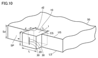
図10は、実施の形態1におけるテラヘルツモジュールを表わす図である。
テラヘルツモジュールは、テラヘルツチップ10と、テラヘルツチップ10と結合される誘電体基板50とを備える。 FIG. 10 is a diagram showing a terahertz module according to the first embodiment.
The terahertz module includes aterahertz chip 10 and a dielectric substrate 50 coupled to the terahertz chip 10.
テラヘルツモジュールは、テラヘルツチップ10と、テラヘルツチップ10と結合される誘電体基板50とを備える。 FIG. 10 is a diagram showing a terahertz module according to the first embodiment.
The terahertz module includes a
誘電体基板50の切り込み部CSに、テラヘルツチップ10が嵌め込まれている。テラヘルツチップ10は、InP基板1の上面が切り込み部CSの第1の側面SPと平行となり、InP基板1が切り込み部CSの奥側に配置されるような向きに嵌め込まれている。テラヘルツチップ10の底面(InP基板1の下面(裏面))が面71Pと接触する。テラヘルツチップ10の2つの側面が、切り込み部CSの2つの面72P、73Pとそれぞれ接触する。
The terahertz chip 10 is fitted in the notch CS of the dielectric substrate 50. The terahertz chip 10 is fitted so that the upper surface of the InP substrate 1 is parallel to the first side surface SP of the notch portion CS and the InP substrate 1 is arranged on the back side of the notch portion CS. The bottom surface of the terahertz chip 10 (the bottom surface (back surface) of the InP substrate 1) comes into contact with the surface 71P. The two sides of the terahertz tip 10 come into contact with the two sides 72P and 73P of the notch CS, respectively.
テラヘルツチップ10の厚さdは、切り込み部CSの深さd2よりも大きい。したがって、テラヘルツチップ10の最も上側の面は、誘電体基板50の外側に配置される。
The thickness d of the terahertz tip 10 is larger than the depth d2 of the cut portion CS. Therefore, the uppermost surface of the terahertz chip 10 is arranged on the outside of the dielectric substrate 50.
本実施の形態では、テラヘルツチップ10の厚さは、任意に設定することができる。テラヘルツチップ10の厚さ方向が、誘電体基板50の表面方向と同じ方向なるので、テラヘルツチップ10を薄膜化する必要がなくなる。
In the present embodiment, the thickness of the terahertz chip 10 can be arbitrarily set. Since the thickness direction of the terahertz chip 10 is the same as the surface direction of the dielectric substrate 50, it is not necessary to thin the terahertz chip 10.
シミュレーション結果によれば、本実施の形態のテラヘルツモジュールは、従来例のテラヘルツモジュールと同様に、90%の結合効率を得ることができることが示されている。
According to the simulation results, it is shown that the terahertz module of the present embodiment can obtain a coupling efficiency of 90% as in the conventional terahertz module.
図11は、実施の形態1のテラヘルツモジュールの実装方法の例を表わす図である。
誘電体基板50の溝84の部分が第1の側面SPに相当する。図示しないが、第1の側面SPに切り込み部CSが形成されて、テラヘルツチップ10が嵌め込まれている。 FIG. 11 is a diagram showing an example of a method of mounting the terahertz module according to the first embodiment.
The portion of thegroove 84 of the dielectric substrate 50 corresponds to the first side surface SP. Although not shown, a notch CS is formed in the first side surface SP, and the terahertz tip 10 is fitted therein.
誘電体基板50の溝84の部分が第1の側面SPに相当する。図示しないが、第1の側面SPに切り込み部CSが形成されて、テラヘルツチップ10が嵌め込まれている。 FIG. 11 is a diagram showing an example of a method of mounting the terahertz module according to the first embodiment.
The portion of the
マイクロ波回路基板80は、金属層80aと樹脂層80bとを備える。同軸コネクタ70からマイクロ波回路基板80の金属層80aに信号および電圧が伝送される。これらの信号および電圧は、さらに、ボンディングワイヤ90を通じてテラヘルツチップ10に送られる。
The microwave circuit board 80 includes a metal layer 80a and a resin layer 80b. A signal and a voltage are transmitted from the coaxial connector 70 to the metal layer 80a of the microwave circuit board 80. These signals and voltages are further sent to the terahertz chip 10 through the bonding wire 90.
以上のように、本実施の形態によれば、誘電体基板の側面に形成された切り込み部にテラヘルツチップを嵌め込んで、テラヘルツチップと誘電体基板とを結合することによって、テラヘルツチップを薄膜化加工することなく、テラヘルツチップと誘電体基板との間で高い結合効率を得ることができる。
As described above, according to the present embodiment, the terahertz chip is thinned by fitting the terahertz chip into the notch formed on the side surface of the dielectric substrate and connecting the terahertz chip and the dielectric substrate. High bonding efficiency can be obtained between the terahertz chip and the dielectric substrate without processing.
[実施の形態2]
図12は、実施の形態2の誘電体基板50を表わす図である。 [Embodiment 2]
FIG. 12 is a diagram showing thedielectric substrate 50 of the second embodiment.
図12は、実施の形態2の誘電体基板50を表わす図である。 [Embodiment 2]
FIG. 12 is a diagram showing the
誘電体基板50の厚さはSdである。誘電体基板50の第1の側面SPに切り込み部CSが形成される。切り込み部CSは、第1の側面SPの上辺USから下辺LSに至るまでに第1の側面SPに対して垂直方向に形成されている。形成される。
The thickness of the dielectric substrate 50 is Sd. A cut portion CS is formed on the first side surface SP of the dielectric substrate 50. The cut portion CS is formed in the direction perpendicular to the first side surface SP from the upper side US to the lower side LS of the first side surface SP. It is formed.
切り込み部CSは、直方体の形状である。切り込み部CSの長さがLであり、幅がwであり、深さがdである。w=Sdである。切り込み部CSは、面74Pと、面75Pと、面76Pとを有する。面74Pは、第1の側面SPと平行である。面75Pおよび面76Pは、第1の側面SPに対して垂直である。
The notch CS has a rectangular parallelepiped shape. The length of the cut portion CS is L, the width is w, and the depth is d. w = Sd. The cut portion CS has a surface 74P, a surface 75P, and a surface 76P. The surface 74P is parallel to the first side surface SP. The surface 75P and the surface 76P are perpendicular to the first side surface SP.
図13は、実施の形態2におけるテラヘルツモジュールを表わす図である。
テラヘルツモジュールは、テラヘルツチップ10と、テラヘルツチップ10と結合される誘電体基板50とを備える。 FIG. 13 is a diagram showing a terahertz module according to the second embodiment.
The terahertz module includes aterahertz chip 10 and a dielectric substrate 50 coupled to the terahertz chip 10.
テラヘルツモジュールは、テラヘルツチップ10と、テラヘルツチップ10と結合される誘電体基板50とを備える。 FIG. 13 is a diagram showing a terahertz module according to the second embodiment.
The terahertz module includes a
誘電体基板50の切り込み部CSに、テラヘルツチップ10が嵌め込まれている。テラヘルツチップ10は、InP基板1の上面が切り込み部CSの第1の側面SPと平行となり、InP基板1が切り込み部CSの奥側に配置されるような向きに嵌め込まれている。テラヘルツチップ10の底面(InP基板1の下面(裏面))が面74Pと接触する。テラヘルツチップ10の2つの側面が、切り込み部CSの2つの面75P、76Pとそれぞれ接触する。
The terahertz chip 10 is fitted in the notch CS of the dielectric substrate 50. The terahertz chip 10 is fitted so that the upper surface of the InP substrate 1 is parallel to the first side surface SP of the notch portion CS and the InP substrate 1 is arranged on the back side of the notch portion CS. The bottom surface of the terahertz chip 10 (the bottom surface (back surface) of the InP substrate 1) comes into contact with the surface 74P. The two sides of the terahertz tip 10 come into contact with the two sides 75P and 76P of the notch CS, respectively.
テラヘルツチップ10の厚さdは、切り込み部CSの深さdと等しい。したがって、テラヘルツチップ10の最も上側の面は、誘電体基板50の第1の側面SPと接続する。
The thickness d of the terahertz tip 10 is equal to the depth d of the notch CS. Therefore, the uppermost surface of the terahertz chip 10 is connected to the first side surface SP of the dielectric substrate 50.
本実施の形態でも、実施の形態1と同様に、テラヘルツチップ10の厚さは、任意に設定することができる。テラヘルツチップ10の厚さ方向が、誘電体基板50の表面方向と同じ方向なるので、テラヘルツチップ10を薄膜化する必要がなくなる。
Also in the present embodiment, the thickness of the terahertz chip 10 can be arbitrarily set as in the first embodiment. Since the thickness direction of the terahertz chip 10 is the same as the surface direction of the dielectric substrate 50, it is not necessary to thin the terahertz chip 10.
[実施の形態3]
図14は、実施の形態3におけるテラヘルツモジュールを表わす図である。 [Embodiment 3]
FIG. 14 is a diagram showing a terahertz module according to the third embodiment.
図14は、実施の形態3におけるテラヘルツモジュールを表わす図である。 [Embodiment 3]
FIG. 14 is a diagram showing a terahertz module according to the third embodiment.
実施の形態2と同様に、誘電体基板50の切り込み部CSにテラヘルツチップ10が嵌め込まれている。テラヘルツチップ10には、ボータイアンテナが形成される。
Similar to the second embodiment, the terahertz chip 10 is fitted in the notch CS of the dielectric substrate 50. A bow tie antenna is formed on the terahertz chip 10.
テラヘルツチップ10は、アンテナ電極4Bおよび2Bと、第1伝送線路(スロット)40Sおよび20Sと、RTD20と、第2伝送線路(スロット)40Fおよび20Fと、パッド電極40Pおよび20Pと、低域通過フィルタ9とを備える。
The terahertz chip 10 includes antenna electrodes 4B and 2B, first transmission lines (slots) 40S and 20S, RTD20, second transmission lines (slots) 40F and 20F, pad electrodes 40P and 20P, and a low-pass filter. 9 and.
アンテナ電極4Bおよび2Bは、自由空間に対してテラヘルツ波を送受信することができる。第1伝送線路40Sおよび20Sは、アンテナ電極4Bおよび2Bに接続され、テラヘルツ波を伝送することができる。
Antenna electrodes 4B and 2B can transmit and receive terahertz waves to free space. The first transmission lines 40S and 20S are connected to the antenna electrodes 4B and 2B and can transmit terahertz waves.
RTD20の主電極がそれぞれ第1伝送線路40Sおよび20Sに接続される。
第2伝送線路40Fおよび20Fは、RTD20に接続され、テラヘルツ波を伝送することができる。 The main electrodes of theRTD 20 are connected to the first transmission lines 40S and 20S, respectively.
The second transmission lines 40F and 20F are connected to the RTD20 and can transmit terahertz waves.
第2伝送線路40Fおよび20Fは、RTD20に接続され、テラヘルツ波を伝送することができる。 The main electrodes of the
The
パッド電極40Pおよび20Pは、第2伝送線路40Fおよび20Fに接続される。
低域通過フィルタ9は、パッド電極40Pおよび20Pに接続される。 The pad electrodes 40P and 20P are connected to the second transmission lines 40F and 20F.
The lowfrequency pass filter 9 is connected to the pad electrodes 40P and 20P.
低域通過フィルタ9は、パッド電極40Pおよび20Pに接続される。 The
The low
第1伝送線路40Sおよび20Sのインピーダンス変換により、アンテナ電極4Bおよび2Bと、RTD20との間をインピーダンス整合することができる。パッド電極20Pおよび40Pは、バイアス電源およびデータ信号供給用電極を構成可能である。
Impedance matching between the antenna electrodes 4B and 2B and the RTD 20 can be performed by impedance conversion of the first transmission lines 40S and 20S. The pad electrodes 20P and 40P can form electrodes for bias power supply and data signal supply.
低域通過フィルタ9は、MIMリフレクタを備えていても良い。パッド電極40Pとパッド電極20Pとの間に接続された抵抗素子を設けても良い。抵抗素子は、金属配線を備えていても良い。金属配線は、ビスマス、ニッケル、チタン、若しくは白金を備えていても良い。
The low frequency pass filter 9 may be provided with a MIM reflector. A resistance element connected between the pad electrode 40P and the pad electrode 20P may be provided. The resistance element may be provided with metal wiring. The metal wiring may include bismuth, nickel, titanium, or platinum.
ボータイアンテナのアンテナ電極4Bと2Bの間隔は、伝送線路(スロット線路)間隔と実質的に等しい。
The distance between the antenna electrodes 4B and 2B of the bow tie antenna is substantially equal to the distance between the transmission lines (slot lines).
RTD20の断面は、実施の形態1の図7において説明したものと同様である。
実施の形態1のスロットアンテナに代えて、テラヘルツチップがボータイアンテナを備える場合においても、実施の形態1と同様の効果が得られる。 The cross section of theRTD 20 is the same as that described in FIG. 7 of the first embodiment.
Even when the terahertz chip includes a bow tie antenna instead of the slot antenna of the first embodiment, the same effect as that of the first embodiment can be obtained.
実施の形態1のスロットアンテナに代えて、テラヘルツチップがボータイアンテナを備える場合においても、実施の形態1と同様の効果が得られる。 The cross section of the
Even when the terahertz chip includes a bow tie antenna instead of the slot antenna of the first embodiment, the same effect as that of the first embodiment can be obtained.
[実施の形態4]
本実施の形態において、上記の実施形態において説明したテラヘルツモジュールの応用例を説明する。 [Embodiment 4]
In this embodiment, an application example of the terahertz module described in the above embodiment will be described.
本実施の形態において、上記の実施形態において説明したテラヘルツモジュールの応用例を説明する。 [Embodiment 4]
In this embodiment, an application example of the terahertz module described in the above embodiment will be described.
誘電体基板50として、フォトニック結晶B1を用いることができる。
図15は、フォトニック結晶B1の斜視図である。図16は、フォトニック結晶B1の平面図である。図17は、フォトニック結晶B1の断面図である。 A photonic crystal B1 can be used as thedielectric substrate 50.
FIG. 15 is a perspective view of the photonic crystal B1. FIG. 16 is a plan view of the photonic crystal B1. FIG. 17 is a cross-sectional view of the photonic crystal B1.
図15は、フォトニック結晶B1の斜視図である。図16は、フォトニック結晶B1の平面図である。図17は、フォトニック結晶B1の断面図である。 A photonic crystal B1 can be used as the
FIG. 15 is a perspective view of the photonic crystal B1. FIG. 16 is a plan view of the photonic crystal B1. FIG. 17 is a cross-sectional view of the photonic crystal B1.
フォトニック結晶B1は、たとえば、二次元フォトニック結晶スラブと称される。フォトニック結晶B1は、たとえば、半導体材料により構成される。フォトニック結晶B1を構成する半導体材料としては、たとえば、Si、GaAs、InP、GaN、GaInAsP/InP、InGaAs/GaAs、GaAlAs/GaAs、GaInNAs/GaAs、GaAlInAs/InP、AlGaInP/GaAs、およびGaInN/GaNなどである。図15および図16において、フォトニック結晶B1の平面視の形状は矩形状であるが、台形状、または他の形状であってもよい。
The photonic crystal B1 is referred to as, for example, a two-dimensional photonic crystal slab. The photonic crystal B1 is made of, for example, a semiconductor material. Examples of the semiconductor material constituting the photonic crystal B1 include Si, GaAs, InP, GaN, GaInAsP / InP, InGaAs / GaAs, GaAlAs / GaAs, GaInNAs / GaAs, GaAlInAs / InP, AlGaInP / GaAs, and GaInN / GaN. And so on. In FIGS. 15 and 16, the shape of the photonic crystal B1 in a plan view is rectangular, but it may be trapezoidal or other shape.
フォトニック結晶B1は、表面41および裏面42を有する。表面41および裏面42いずれも平坦である。フォトニック結晶B1の第1の側面SPの切り込み部(図示は省略)にテラヘルツチップ10が嵌め込まれる。
The photonic crystal B1 has a front surface 41 and a back surface 42. Both the front surface 41 and the back surface 42 are flat. The terahertz chip 10 is fitted into the notch (not shown) of the first side surface SP of the photonic crystal B1.
フォトニック結晶B1は、複数の格子点31を含む。複数の格子点31は、フォトニック結晶B1のフォトニックバンド構造のフォトニックバンドギャップ帯におけるテラヘルツ波を回折させる。複数の格子点31は、フォトニック結晶B1のXY平面において周期的に配置されている。複数の格子点31は各々、たとえば、孔により構成される。図17に示すように、孔は、フォトニック結晶B1を貫通しており、表面41から裏面42に至っている。図15および図16では、孔の形状は円形であるが、多角形または楕円形であってもよい。また、図15および図16では、正方格子の周期配列が示されているが、長方格子、三角格子、または蜂の巣格子などの2次元的な周期配列であってもよい。
The photonic crystal B1 includes a plurality of lattice points 31. The plurality of lattice points 31 diffract the terahertz wave in the photonic band gap zone of the photonic band structure of the photonic crystal B1. The plurality of lattice points 31 are periodically arranged in the XY plane of the photonic crystal B1. Each of the plurality of grid points 31 is composed of, for example, holes. As shown in FIG. 17, the hole penetrates the photonic crystal B1 and reaches from the front surface 41 to the back surface 42. In FIGS. 15 and 16, the shape of the holes is circular, but may be polygonal or elliptical. Further, although the periodic array of the square lattice is shown in FIGS. 15 and 16, it may be a two-dimensional periodic array such as a rectangular lattice, a triangular lattice, or a honeycomb lattice.
格子点31の格子定数を調整することによって、テラヘルツ波の屈折率を変化させることができる。これによって、テラヘルツ波の伝搬経路を制御することができる。たとえば、伝送経路を直線、曲げ、分岐(分波)、交差、方向性結合(合波)することができる。また、フォトニック結晶B1は、屈折率閉じ込め構造を利用したコンパクトな伝送路、フィルタ、レンズなどの非線形光学素子、アンテナなどを平面集積化することができる。
The refractive index of the terahertz wave can be changed by adjusting the lattice constant of the lattice point 31. This makes it possible to control the propagation path of the terahertz wave. For example, the transmission path can be straight, bent, branched (branched), crossed, or directionally coupled (combined). Further, the photonic crystal B1 can integrate a compact transmission line using a refractive index confinement structure, a nonlinear optical element such as a filter and a lens, an antenna, and the like in a plane.
以下では、誘電体基板50として、フォトニック結晶B1を用いた5つの応用例を説明する。
Below, five application examples using the photonic crystal B1 as the dielectric substrate 50 will be described.
図18は、テラヘルツモジュールの第1の応用例を表わす図である。
誘電体基板50は、格子点31の格子定数を調整して屈折率分布を形成することによって、テラヘルツ波の誘電体導波路110を形成することができる。誘電体導波路110は、InP基板1の上面及び下面に垂直方向に形成される。InP基板1の上面および下面は、誘電体基板50の第1の側面SP、切り込み部CSの面71P、および切り込み部CSの面74Pと平行である。 FIG. 18 is a diagram showing a first application example of the terahertz module.
Thedielectric substrate 50 can form a terahertz wave dielectric waveguide 110 by adjusting the lattice constant of the lattice points 31 to form a refractive index distribution. The dielectric waveguide 110 is formed in the vertical direction on the upper surface and the lower surface of the InP substrate 1. The upper and lower surfaces of the InP substrate 1 are parallel to the first side surface SP of the dielectric substrate 50, the surface 71P of the notch CS, and the surface 74P of the notch CS.
誘電体基板50は、格子点31の格子定数を調整して屈折率分布を形成することによって、テラヘルツ波の誘電体導波路110を形成することができる。誘電体導波路110は、InP基板1の上面及び下面に垂直方向に形成される。InP基板1の上面および下面は、誘電体基板50の第1の側面SP、切り込み部CSの面71P、および切り込み部CSの面74Pと平行である。 FIG. 18 is a diagram showing a first application example of the terahertz module.
The
図19は、テラヘルツモジュールの第2の応用例を表わす図である。
誘電体基板50は、格子点の格子定数を調整して屈折率分布を形成することによって、平面レンズ112を形成することができる。図19に示すように、テラヘルツチップ10から放射されたテラヘルツ波が平面レンズ112によって集光される。 FIG. 19 is a diagram showing a second application example of the terahertz module.
Thedielectric substrate 50 can form a planar lens 112 by adjusting the lattice constant of the lattice points to form a refractive index distribution. As shown in FIG. 19, the terahertz wave radiated from the terahertz chip 10 is collected by the planar lens 112.
誘電体基板50は、格子点の格子定数を調整して屈折率分布を形成することによって、平面レンズ112を形成することができる。図19に示すように、テラヘルツチップ10から放射されたテラヘルツ波が平面レンズ112によって集光される。 FIG. 19 is a diagram showing a second application example of the terahertz module.
The
なお、誘電体基板50は、格子点の格子定数を調整することによって、平面レンズ112ではなく、テラヘルツ波を反射する反射鏡、またはテラヘルツ波の定められた周波数成分を通過または除去するフィルタなどを形成することができる。
The dielectric substrate 50 is not a flat lens 112 but a reflector that reflects a terahertz wave or a filter that passes or removes a defined frequency component of the terahertz wave by adjusting the lattice constants of the lattice points. Can be formed.
図20は、テラヘルツモジュールの第3の応用例を表わす図である。
複数のテラヘルツチップ10を1列に配置して、フォトニック結晶に結合することによって、テラヘルツチップアレイが形成される。複数のテラヘルツチップ10は、駆動電圧の相違によって、互いに別個の周波数のテラヘルツ波を放射する。複数のテラヘルツチップ10から放射されたテラヘルツ波が平面レンズ112によって集光され、出力用導波路119を通じて出力される。 FIG. 20 is a diagram showing a third application example of the terahertz module.
A terahertz chip array is formed by arranging a plurality ofterahertz chips 10 in a row and binding them to a photonic crystal. The plurality of terahertz chips 10 emit terahertz waves having frequencies different from each other due to the difference in drive voltage. The terahertz waves radiated from the plurality of terahertz chips 10 are collected by the planar lens 112 and output through the output waveguide 119.
複数のテラヘルツチップ10を1列に配置して、フォトニック結晶に結合することによって、テラヘルツチップアレイが形成される。複数のテラヘルツチップ10は、駆動電圧の相違によって、互いに別個の周波数のテラヘルツ波を放射する。複数のテラヘルツチップ10から放射されたテラヘルツ波が平面レンズ112によって集光され、出力用導波路119を通じて出力される。 FIG. 20 is a diagram showing a third application example of the terahertz module.
A terahertz chip array is formed by arranging a plurality of
図21は、テラヘルツモジュールの第4の応用例を表わす図である。
フォトニック結晶に形成されたフィルタによって、周波数多重化を実現することができる。周波数に応じて、合波または分波が可能となる。 FIG. 21 is a diagram showing a fourth application example of the terahertz module.
Frequency multiplexing can be achieved by a filter formed in a photonic crystal. Depending on the frequency, it can be combined or demultiplexed.
フォトニック結晶に形成されたフィルタによって、周波数多重化を実現することができる。周波数に応じて、合波または分波が可能となる。 FIG. 21 is a diagram showing a fourth application example of the terahertz module.
Frequency multiplexing can be achieved by a filter formed in a photonic crystal. Depending on the frequency, it can be combined or demultiplexed.
複数のテラヘルツチップ10は、互いに別個の周波数のテラヘルツ波を放射する。
複数のテラヘルツチップ10から放射されたテラヘルツ波が分波器181によって分波され、複数の導波路183へ送られる。複数の導波路183から出力された複数の周波数のテラヘルツ波は、合波器182によって多重化される。多重化されたテラヘルツ波はアンテナへ出力される。 The plurality ofterahertz chips 10 emit terahertz waves having frequencies different from each other.
The terahertz wave radiated from the plurality ofterahertz chips 10 is demultiplexed by the duplexer 181 and sent to the plurality of waveguides 183. The terahertz waves of a plurality of frequencies output from the plurality of waveguides 183 are multiplexed by the combiner 182. The multiplexed terahertz wave is output to the antenna.
複数のテラヘルツチップ10から放射されたテラヘルツ波が分波器181によって分波され、複数の導波路183へ送られる。複数の導波路183から出力された複数の周波数のテラヘルツ波は、合波器182によって多重化される。多重化されたテラヘルツ波はアンテナへ出力される。 The plurality of
The terahertz wave radiated from the plurality of
図22は、テラヘルツモジュールの第5の応用例を表わす図である。
フォトニック結晶に、共振器117、カップラ133、ミキサ132、吸収体134が形成される。 FIG. 22 is a diagram showing a fifth application example of the terahertz module.
Aresonator 117, a coupler 133, a mixer 132, and an absorber 134 are formed on the photonic crystal.
フォトニック結晶に、共振器117、カップラ133、ミキサ132、吸収体134が形成される。 FIG. 22 is a diagram showing a fifth application example of the terahertz module.
A
局部発振器131は、複数のテラヘルツチップ10が1列に配置されたアレイと、合成レンズ115と、高いQ値を有する共振器117とを備える。
The local oscillator 131 includes an array in which a plurality of terahertz chips 10 are arranged in a row, a synthetic lens 115, and a resonator 117 having a high Q value.
局部発振器131から放射された局部発振信号LOの一部が、吸収体134へ送られ、残りが、カップラ133へ送られる。吸収体134によって、局部発振信号LOが反射されるのを防止することができる。
A part of the local oscillation signal LO radiated from the local oscillator 131 is sent to the absorber 134, and the rest is sent to the coupler 133. The absorber 134 can prevent the local oscillation signal LO from being reflected.
カップラ133は、局部発振信号LOをミキサ132へ送り、ミキサ132から出力された変調信号RFを通さない。
The coupler 133 sends the local oscillation signal LO to the mixer 132 and does not pass through the modulation signal RF output from the mixer 132.
ミキサ132は、中間周波数信号IFと局部発振信号LOとを混合することによって、変調信号RFを生成して、アンテナへ放射する。
The mixer 132 generates a modulated signal RF by mixing the intermediate frequency signal IF and the local oscillation signal LO, and radiates it to the antenna.
[シミュレーション]
次に、シミュレーションの結果を説明する。 [simulation]
Next, the result of the simulation will be described.
次に、シミュレーションの結果を説明する。 [simulation]
Next, the result of the simulation will be described.
図23は、シミュレーション結果を表わす図である。
図23において、図11に示すマイクロ波回路基板80を設けた場合の透過率と、マイクロ波回路基板80を設けなかった場合の透過率が表されている。図23に示すように、両者の差は、約1dB程度である。マイクロ波回路基板80を設けることによる透過率への影響は十分に小さいことが示される。 FIG. 23 is a diagram showing a simulation result.
In FIG. 23, the transmittance when themicrowave circuit board 80 shown in FIG. 11 is provided and the transmittance when the microwave circuit board 80 is not provided are shown. As shown in FIG. 23, the difference between the two is about 1 dB. It is shown that the effect of providing the microwave circuit board 80 on the transmittance is sufficiently small.
図23において、図11に示すマイクロ波回路基板80を設けた場合の透過率と、マイクロ波回路基板80を設けなかった場合の透過率が表されている。図23に示すように、両者の差は、約1dB程度である。マイクロ波回路基板80を設けることによる透過率への影響は十分に小さいことが示される。 FIG. 23 is a diagram showing a simulation result.
In FIG. 23, the transmittance when the
[変形例]
本開示は、上記の実施形態に限定されるものではない。たとえば、以下のような変形例も含む。 [Modification example]
The present disclosure is not limited to the above embodiments. For example, the following modification examples are also included.
本開示は、上記の実施形態に限定されるものではない。たとえば、以下のような変形例も含む。 [Modification example]
The present disclosure is not limited to the above embodiments. For example, the following modification examples are also included.
(1)上記の実施形態では、能動素子の例としてRTDを用いたが、これ以外のダイオードまたはトランジスタでも構成可能である。例えば、能動素子として、タンネット(TUNNETT:Tunnel Transit Time)ダイオード、インパット(IMPATT:Impact Ionization Avalanche Transit Time)ダイオード、GaAs系電界効果トランジスタ(FET:Field Effect Transistor)、GaN系FET、高電子移動度トランジスタ(HEMT:High Electron Mobility Transistor)、ヘテロ接合バイポーラトランジスタ(HBT:Heterojunction Bipolar Transistor)若しくはCMOS(Complementary Metal-Oxide-Semiconductor)FETなどを用いることもできる。
(1) In the above embodiment, RTD is used as an example of the active element, but other diodes or transistors can also be configured. For example, as active elements, a tannet (TUNNETT: Tunnel Transit Time) diode, an impat (IMPATT: Impact Ionization Avalanche Transit Time) diode, a GaAs-based field effect transistor (FET: Field Effect Transistor), a GaN-based FET, and high electron mobility. Transistors (HEMT: High Electron Mobility Transistor), heterojunction bipolar transistors (HBT: Heterojunction Bipolar Transistor), CMOS (Complementary Metal-Oxide-Semiconductor) FETs, and the like can also be used.
(2)テラヘルツチップは、第1トンネルバリア層/量子井戸(QW:Quantum Well)層/第2トンネルバリア層が、AlAs/GaInAs/AlAsの構成を有する例が示されているが、このような材料系に限定されるものではない。例えば、第1トンネルバリア層/量子井戸層/第2トンネルバリア層が、AlGaAs/GaAs/AlGaAsの構成を有する例であっても良い。また、第1トンネルバリア層/量子井戸層/第2トンネルバリア層が、AlGaN/GaN/AlGaNの構成を有する例であっても良い。また、第1トンネルバリア層/量子井戸層/第2トンネルバリア層が、SiGe/Si/SiGeの構成を有する例であっても良い。
(2) As for the terahertz chip, an example is shown in which the first tunnel barrier layer / quantum well (QW: Quantum Well) layer / second tunnel barrier layer has an AlAs / GaInAs / AlAs configuration. It is not limited to the material system. For example, the first tunnel barrier layer / quantum well layer / second tunnel barrier layer may have an AlGaAs / GaAs / AlGaAs configuration. Further, the first tunnel barrier layer / quantum well layer / second tunnel barrier layer may have an AlGaN / GaN / AlGaN configuration. Further, the first tunnel barrier layer / quantum well layer / second tunnel barrier layer may be an example having a SiGe / Si / SiGe configuration.
(3)上記の実施形態では、テラヘルツチップは、スロットアンテナ、またはボータイアンテナを備えるものとしたが、これに限定するものではない。テラヘルツチップが備えるアンテナは、電波(テラヘルツ波)が基板の垂直方向に放射するようなものであれば、その形状は問わない。たとえば、テラヘルツチップは、パッチアンテナ、ダイポールアンテナ、またはリングアンテナ等の平面アンテナを備えるものとしてもよい。
(3) In the above embodiment, the terahertz chip is provided with a slot antenna or a bow tie antenna, but the terahertz chip is not limited to this. The antenna provided in the terahertz chip may have any shape as long as the radio wave (terahertz wave) radiates in the vertical direction of the substrate. For example, the terahertz chip may include a planar antenna such as a patch antenna, a dipole antenna, or a ring antenna.
今回開示された実施の形態はすべての点で例示であって制限的なものではないと考えられるべきである。本開示の範囲は上記した説明ではなくて請求の範囲によって示され、請求の範囲と均等の意味および範囲内でのすべての変更が含まれることが意図される。
The embodiments disclosed this time should be considered to be exemplary in all respects and not restrictive. The scope of the present disclosure is shown by the scope of claims rather than the above description, and is intended to include all modifications within the meaning and scope of the claims.
1,191 InP基板、2 下部電極、4 上部電極、4B アンテナ電極、6a,6b MIMキャパシタ、9 低域通過フィルタ、10,192 テラヘルツチップ、20 RTD、30 スロット、20P,40P パッド電極、31 格子点、40F 第2伝送線路、40S 第1伝送線路、41 表面、42 裏面、50 誘電体基板、70 同軸コネクタ、71P,72P,73P,74P,75P,76P 面、80 マイクロ波回路基板、80a マイクロ波回路基板の金属層、80b マイクロ波回路基板の樹脂層、84 溝、90 ボンディングワイヤ、91a,91b,92a,92b,93a,93b,94a,94b,95 層、98,98a,98b SiO2膜、110 誘電体導波路、112 平面レンズ、115 合成レンズ、117 共振器、119 出力用導波路、131 局部発振器、132 ミキサ、133 カップラ、134 吸収体、139a,139b 導電路、181 分波器、182 合波器、183 導波路、B1 フォトニック結晶、CS 切り込み部、LS 下辺、SP 側面、SR1,SR2 シャント抵抗、US 上辺。
1,191 InP board, 2 lower electrode, 4 upper electrode, 4B antenna electrode, 6a, 6b MIM capacitor, 9 low frequency pass filter, 10,192 terahertz chip, 20 RTD, 30 slot, 20P, 40P pad electrode, 31 lattice Point, 40F 2nd transmission line, 40S 1st transmission line, 41 front surface, 42 back surface, 50 dielectric substrate, 70 coaxial connector, 71P, 72P, 73P, 74P, 75P, 76P surface, 80 microwave circuit board, 80a micro Metal layer of wave circuit board, resin layer of 80b microwave circuit board, 84 grooves, 90 bonding wire, 91a, 91b, 92a, 92b, 93a, 93b, 94a, 94b, 95 layers, 98, 98a, 98b SiO 2 film , 110 Dielectric Waveguide, 112 Planar Lens, 115 Synthetic Lens, 117 Resonator, 119 Output Waveguide, 131 Local Oscillator, 132 Mixer, 133 Coupler, 134 Absorber, 139a, 139b Conductor, 181 Demultiplexer, 182 combiner, 183 waveguide, B1 photonic crystal, CS notch, LS bottom side, SP side surface, SR1, SR2 shunt resistance, US top side.
Claims (10)
- テラヘルツ波を放射する能動素子を含むテラヘルツチップと、
前記テラヘルツチップと結合される誘電体基板とを備え、
前記テラヘルツチップは、半導体基板を含み、前記能動素子は、前記半導体基板の上面に配置され、
前記誘電体基板の複数の側面のうちの第1の側面の一部に、前記第1の側面の上辺から下辺に至るまでの切り込み部が形成され、
前記テラヘルツチップは、前記半導体基板の上面が前記第1の側面と平行となり、かつ前記半導体基板が前記切り込み部の奥側に配置されるような向きに嵌め込まれている、テラヘルツモジュール。 A terahertz chip containing an active element that emits terahertz waves,
A dielectric substrate to be coupled to the terahertz chip is provided.
The terahertz chip includes a semiconductor substrate, and the active element is arranged on the upper surface of the semiconductor substrate.
A notch from the upper side to the lower side of the first side surface is formed on a part of the first side surface of the plurality of side surfaces of the dielectric substrate.
The terahertz chip is a terahertz module in which the upper surface of the semiconductor substrate is parallel to the first side surface and the semiconductor substrate is fitted so as to be arranged on the inner side of the notch. - 前記切り込み部は、前記第1の側面に平行な面を有し、
前記半導体基板の下面が、前記第1の側面に平行な前記切り込み部の面と接触する、請求項1記載のテラヘルツモジュール。 The cut portion has a surface parallel to the first side surface and has a surface parallel to the first side surface.
The terahertz module according to claim 1, wherein the lower surface of the semiconductor substrate is in contact with the surface of the notch portion parallel to the first side surface. - 前記テラヘルツチップの厚さは、前記切り込み部の深さと同じである、請求項1または2記載のテラヘルツモジュール。 The terahertz module according to claim 1 or 2, wherein the thickness of the terahertz chip is the same as the depth of the notch.
- 前記テラヘルツチップの厚さは、前記切り込み部の深さよりも大きい、請求項1または2記載のテラヘルツモジュール。 The terahertz module according to claim 1 or 2, wherein the thickness of the terahertz chip is larger than the depth of the notch.
- 前記誘電体基板は、フォトニック結晶である、請求項1~4のいずれか1項に記載のテラヘルツモジュール。 The terahertz module according to any one of claims 1 to 4, wherein the dielectric substrate is a photonic crystal.
- 前記フォトニック結晶には、前記半導体基板の上面に垂直な方向に前記テラヘルツ波の導波路が形成される、請求項5記載のテラヘルツモジュール。 The terahertz module according to claim 5, wherein the terahertz wave waveguide is formed in the photonic crystal in a direction perpendicular to the upper surface of the semiconductor substrate.
- 前記フォトニック結晶に、前記テラヘルツ波の定められた周波数成分を通過または除去するフィルタが形成される、請求項5記載のテラヘルツモジュール。 The terahertz module according to claim 5, wherein a filter for passing or removing a defined frequency component of the terahertz wave is formed on the photonic crystal.
- 前記フォトニック結晶には、前記能動素子から放射された前記テラヘルツ波を集光する平面レンズが形成される、請求項5記載のテラヘルツモジュール。 The terahertz module according to claim 5, wherein a planar lens that collects the terahertz wave radiated from the active element is formed on the photonic crystal.
- 1列に配置された複数個の前記テラヘルツチップが、前記フォトニック結晶に結合される、請求項5記載のテラヘルツモジュール。 The terahertz module according to claim 5, wherein a plurality of the terahertz chips arranged in one row are bonded to the photonic crystal.
- 前記能動素子は、共鳴トンネルダイオードである、請求項1~9のいずれか1項に記載のテラヘルツモジュール。 The terahertz module according to any one of claims 1 to 9, wherein the active element is a resonance tunnel diode.
Priority Applications (3)
| Application Number | Priority Date | Filing Date | Title |
|---|---|---|---|
| US18/003,819 US20230260913A1 (en) | 2020-07-20 | 2021-07-08 | Terahertz module |
| JP2022537919A JPWO2022019136A1 (en) | 2020-07-20 | 2021-07-08 | |
| DE112021003317.4T DE112021003317T5 (en) | 2020-07-20 | 2021-07-08 | terahertz module |
Applications Claiming Priority (2)
| Application Number | Priority Date | Filing Date | Title |
|---|---|---|---|
| JP2020-123912 | 2020-07-20 | ||
| JP2020123912 | 2020-07-20 |
Publications (1)
| Publication Number | Publication Date |
|---|---|
| WO2022019136A1 true WO2022019136A1 (en) | 2022-01-27 |
Family
ID=79728698
Family Applications (1)
| Application Number | Title | Priority Date | Filing Date |
|---|---|---|---|
| PCT/JP2021/025773 WO2022019136A1 (en) | 2020-07-20 | 2021-07-08 | Terahertz module |
Country Status (4)
| Country | Link |
|---|---|
| US (1) | US20230260913A1 (en) |
| JP (1) | JPWO2022019136A1 (en) |
| DE (1) | DE112021003317T5 (en) |
| WO (1) | WO2022019136A1 (en) |
Cited By (1)
| Publication number | Priority date | Publication date | Assignee | Title |
|---|---|---|---|---|
| WO2024009769A1 (en) * | 2022-07-04 | 2024-01-11 | ローム株式会社 | Terahertz device |
Citations (5)
| Publication number | Priority date | Publication date | Assignee | Title |
|---|---|---|---|---|
| US20050191774A1 (en) * | 2002-10-28 | 2005-09-01 | Zhiyong Li | Photonic crystals with nanowire-based fabrication |
| US20110169405A1 (en) * | 2010-01-11 | 2011-07-14 | Samsung Electronics Co., Ltd. | Terahertz radiation sources and methods of manufacturing the same |
| JP2014197837A (en) * | 2013-03-04 | 2014-10-16 | 国立大学法人大阪大学 | Terahertz wave connector, terahertz wave integrated circuit, waveguide, and antenna structure |
| JP2015187716A (en) * | 2014-03-12 | 2015-10-29 | 国立大学法人大阪大学 | Terahertz wave device and terahertz wave integrated circuit |
| US20190044211A1 (en) * | 2017-08-03 | 2019-02-07 | California Institute Of Technology | Millimeter-wave coupler for semi-confocal fabry-perot cavity |
-
2021
- 2021-07-08 JP JP2022537919A patent/JPWO2022019136A1/ja active Pending
- 2021-07-08 DE DE112021003317.4T patent/DE112021003317T5/en active Pending
- 2021-07-08 US US18/003,819 patent/US20230260913A1/en active Pending
- 2021-07-08 WO PCT/JP2021/025773 patent/WO2022019136A1/en active Application Filing
Patent Citations (5)
| Publication number | Priority date | Publication date | Assignee | Title |
|---|---|---|---|---|
| US20050191774A1 (en) * | 2002-10-28 | 2005-09-01 | Zhiyong Li | Photonic crystals with nanowire-based fabrication |
| US20110169405A1 (en) * | 2010-01-11 | 2011-07-14 | Samsung Electronics Co., Ltd. | Terahertz radiation sources and methods of manufacturing the same |
| JP2014197837A (en) * | 2013-03-04 | 2014-10-16 | 国立大学法人大阪大学 | Terahertz wave connector, terahertz wave integrated circuit, waveguide, and antenna structure |
| JP2015187716A (en) * | 2014-03-12 | 2015-10-29 | 国立大学法人大阪大学 | Terahertz wave device and terahertz wave integrated circuit |
| US20190044211A1 (en) * | 2017-08-03 | 2019-02-07 | California Institute Of Technology | Millimeter-wave coupler for semi-confocal fabry-perot cavity |
Cited By (1)
| Publication number | Priority date | Publication date | Assignee | Title |
|---|---|---|---|---|
| WO2024009769A1 (en) * | 2022-07-04 | 2024-01-11 | ローム株式会社 | Terahertz device |
Also Published As
| Publication number | Publication date |
|---|---|
| US20230260913A1 (en) | 2023-08-17 |
| JPWO2022019136A1 (en) | 2022-01-27 |
| DE112021003317T5 (en) | 2023-04-06 |
Similar Documents
| Publication | Publication Date | Title |
|---|---|---|
| JP6478220B2 (en) | Terahertz device and terahertz integrated circuit | |
| US7884764B2 (en) | Active antenna oscillator | |
| US7898348B2 (en) | Terahertz oscillation device | |
| US9391428B2 (en) | Waveguide element | |
| JP6635376B2 (en) | Terahertz element and terahertz integrated circuit | |
| US9904015B2 (en) | Optoelectronic integrated circuitry for transmitting and/or receiving wavelength-division multiplexed optical signals | |
| JP3905367B2 (en) | Semiconductor optical modulator, Mach-Zehnder optical modulator using the same, and method for manufacturing the semiconductor optical modulator | |
| JP6099114B2 (en) | Wireless transmission device | |
| US10277167B2 (en) | Oscillation element and oscillator using the same | |
| JP5808560B2 (en) | Terahertz oscillation detector | |
| JP5958890B2 (en) | Terahertz detector | |
| WO2022019136A1 (en) | Terahertz module | |
| JP5746526B2 (en) | Terahertz wireless communication system | |
| US4568889A (en) | Distributed diode VCO with stripline coupled output and distributed variable capacitor control | |
| JP2002118324A (en) | Semiconductor ring laser | |
| US4525732A (en) | Distributed IMPATT structure | |
| JP2016158023A (en) | Terahertz element | |
| JP4382585B2 (en) | Optical modulator and characteristic control method | |
| US4539528A (en) | Two-port amplifier | |
| CN108988124B (en) | Monolithic integration tunnel junction laser for microwave oscillation source | |
| JP3505509B2 (en) | Semiconductor light emitting device, semiconductor light emitting device, and method for modulating semiconductor light emitting device | |
| JP4845049B2 (en) | Oscillator and wireless relay system | |
| WO2023199965A1 (en) | Antenna device, communication device, and imaging system | |
| US11927839B2 (en) | Broadband electro-absorption optical modulator using on-chip RF input signal termination | |
| JP5417199B2 (en) | Oscillating element |
Legal Events
| Date | Code | Title | Description |
|---|---|---|---|
| 121 | Ep: the epo has been informed by wipo that ep was designated in this application |
Ref document number: 21846069 Country of ref document: EP Kind code of ref document: A1 |
|
| ENP | Entry into the national phase |
Ref document number: 2022537919 Country of ref document: JP Kind code of ref document: A |
|
| 122 | Ep: pct application non-entry in european phase |
Ref document number: 21846069 Country of ref document: EP Kind code of ref document: A1 |