WO2022017322A1 - 图腾柱pfc电路、控制方法、线路板及空调器 - Google Patents
图腾柱pfc电路、控制方法、线路板及空调器 Download PDFInfo
- Publication number
- WO2022017322A1 WO2022017322A1 PCT/CN2021/107105 CN2021107105W WO2022017322A1 WO 2022017322 A1 WO2022017322 A1 WO 2022017322A1 CN 2021107105 W CN2021107105 W CN 2021107105W WO 2022017322 A1 WO2022017322 A1 WO 2022017322A1
- Authority
- WO
- WIPO (PCT)
- Prior art keywords
- switch
- switch tube
- module
- diode
- time period
- Prior art date
- Legal status (The legal status is an assumption and is not a legal conclusion. Google has not performed a legal analysis and makes no representation as to the accuracy of the status listed.)
- Ceased
Links
Images




Classifications
-
- H—ELECTRICITY
- H02—GENERATION; CONVERSION OR DISTRIBUTION OF ELECTRIC POWER
- H02M—APPARATUS FOR CONVERSION BETWEEN AC AND AC, BETWEEN AC AND DC, OR BETWEEN DC AND DC, AND FOR USE WITH MAINS OR SIMILAR POWER SUPPLY SYSTEMS; CONVERSION OF DC OR AC INPUT POWER INTO SURGE OUTPUT POWER; CONTROL OR REGULATION THEREOF
- H02M1/00—Details of apparatus for conversion
- H02M1/42—Circuits or arrangements for compensating for or adjusting power factor in converters or inverters
- H02M1/4208—Arrangements for improving power factor of AC input
- H02M1/4233—Arrangements for improving power factor of AC input using a bridge converter comprising active switches
-
- H—ELECTRICITY
- H02—GENERATION; CONVERSION OR DISTRIBUTION OF ELECTRIC POWER
- H02M—APPARATUS FOR CONVERSION BETWEEN AC AND AC, BETWEEN AC AND DC, OR BETWEEN DC AND DC, AND FOR USE WITH MAINS OR SIMILAR POWER SUPPLY SYSTEMS; CONVERSION OF DC OR AC INPUT POWER INTO SURGE OUTPUT POWER; CONTROL OR REGULATION THEREOF
- H02M1/00—Details of apparatus for conversion
- H02M1/12—Arrangements for reducing harmonics from AC input or output
-
- H—ELECTRICITY
- H02—GENERATION; CONVERSION OR DISTRIBUTION OF ELECTRIC POWER
- H02M—APPARATUS FOR CONVERSION BETWEEN AC AND AC, BETWEEN AC AND DC, OR BETWEEN DC AND DC, AND FOR USE WITH MAINS OR SIMILAR POWER SUPPLY SYSTEMS; CONVERSION OF DC OR AC INPUT POWER INTO SURGE OUTPUT POWER; CONTROL OR REGULATION THEREOF
- H02M1/00—Details of apparatus for conversion
- H02M1/42—Circuits or arrangements for compensating for or adjusting power factor in converters or inverters
-
- H—ELECTRICITY
- H02—GENERATION; CONVERSION OR DISTRIBUTION OF ELECTRIC POWER
- H02M—APPARATUS FOR CONVERSION BETWEEN AC AND AC, BETWEEN AC AND DC, OR BETWEEN DC AND DC, AND FOR USE WITH MAINS OR SIMILAR POWER SUPPLY SYSTEMS; CONVERSION OF DC OR AC INPUT POWER INTO SURGE OUTPUT POWER; CONTROL OR REGULATION THEREOF
- H02M1/00—Details of apparatus for conversion
- H02M1/42—Circuits or arrangements for compensating for or adjusting power factor in converters or inverters
- H02M1/4208—Arrangements for improving power factor of AC input
- H02M1/4225—Arrangements for improving power factor of AC input using a non-isolated boost converter
-
- H—ELECTRICITY
- H02—GENERATION; CONVERSION OR DISTRIBUTION OF ELECTRIC POWER
- H02M—APPARATUS FOR CONVERSION BETWEEN AC AND AC, BETWEEN AC AND DC, OR BETWEEN DC AND DC, AND FOR USE WITH MAINS OR SIMILAR POWER SUPPLY SYSTEMS; CONVERSION OF DC OR AC INPUT POWER INTO SURGE OUTPUT POWER; CONTROL OR REGULATION THEREOF
- H02M7/00—Conversion of AC power input into DC power output; Conversion of DC power input into AC power output
- H02M7/02—Conversion of AC power input into DC power output without possibility of reversal
- H02M7/04—Conversion of AC power input into DC power output without possibility of reversal by static converters
-
- H—ELECTRICITY
- H02—GENERATION; CONVERSION OR DISTRIBUTION OF ELECTRIC POWER
- H02M—APPARATUS FOR CONVERSION BETWEEN AC AND AC, BETWEEN AC AND DC, OR BETWEEN DC AND DC, AND FOR USE WITH MAINS OR SIMILAR POWER SUPPLY SYSTEMS; CONVERSION OF DC OR AC INPUT POWER INTO SURGE OUTPUT POWER; CONTROL OR REGULATION THEREOF
- H02M7/00—Conversion of AC power input into DC power output; Conversion of DC power input into AC power output
- H02M7/02—Conversion of AC power input into DC power output without possibility of reversal
- H02M7/04—Conversion of AC power input into DC power output without possibility of reversal by static converters
- H02M7/12—Conversion of AC power input into DC power output without possibility of reversal by static converters using discharge tubes with control electrode or semiconductor devices with control electrode
- H02M7/21—Conversion of AC power input into DC power output without possibility of reversal by static converters using discharge tubes with control electrode or semiconductor devices with control electrode using devices of a triode or transistor type requiring continuous application of a control signal
- H02M7/217—Conversion of AC power input into DC power output without possibility of reversal by static converters using discharge tubes with control electrode or semiconductor devices with control electrode using devices of a triode or transistor type requiring continuous application of a control signal using semiconductor devices only
- H02M7/219—Conversion of AC power input into DC power output without possibility of reversal by static converters using discharge tubes with control electrode or semiconductor devices with control electrode using devices of a triode or transistor type requiring continuous application of a control signal using semiconductor devices only in a bridge configuration
-
- H—ELECTRICITY
- H02—GENERATION; CONVERSION OR DISTRIBUTION OF ELECTRIC POWER
- H02P—CONTROL OR REGULATION OF ELECTRIC MOTORS, ELECTRIC GENERATORS OR DYNAMO-ELECTRIC CONVERTERS; CONTROLLING TRANSFORMERS, REACTORS OR CHOKE COILS
- H02P27/00—Arrangements or methods for the control of AC motors characterised by the kind of supply voltage
- H02P27/04—Arrangements or methods for the control of AC motors characterised by the kind of supply voltage using variable-frequency supply voltage, e.g. inverter or converter supply voltage
- H02P27/06—Arrangements or methods for the control of AC motors characterised by the kind of supply voltage using variable-frequency supply voltage, e.g. inverter or converter supply voltage using DC to AC converters or inverters
-
- Y—GENERAL TAGGING OF NEW TECHNOLOGICAL DEVELOPMENTS; GENERAL TAGGING OF CROSS-SECTIONAL TECHNOLOGIES SPANNING OVER SEVERAL SECTIONS OF THE IPC; TECHNICAL SUBJECTS COVERED BY FORMER USPC CROSS-REFERENCE ART COLLECTIONS [XRACs] AND DIGESTS
- Y02—TECHNOLOGIES OR APPLICATIONS FOR MITIGATION OR ADAPTATION AGAINST CLIMATE CHANGE
- Y02B—CLIMATE CHANGE MITIGATION TECHNOLOGIES RELATED TO BUILDINGS, e.g. HOUSING, HOUSE APPLIANCES OR RELATED END-USER APPLICATIONS
- Y02B70/00—Technologies for an efficient end-user side electric power management and consumption
- Y02B70/10—Technologies improving the efficiency by using switched-mode power supplies [SMPS], i.e. efficient power electronics conversion e.g. power factor correction or reduction of losses in power supplies or efficient standby modes
Definitions
- the invention relates to the technical field of air conditioners, in particular to a totem pole PFC circuit, a control method, a circuit board and an air conditioner.
- totem pole PFC circuits and voltage doubler circuits are both very commonly used current topologies.
- the totem pole PFC topology can boost the rectified voltage
- the voltage doubler circuit can double the output voltage of the rectifier circuit, but cannot boost the voltage.
- Both circuit topologies have their own advantages. If the two circuits are simply combined, the conduction loss of the system will be large, the harmonic content will be high, and the voltage conversion efficiency will be low.
- the purpose of the present invention is to solve at least one of the technical problems existing in the prior art, and to provide a totem pole PFC circuit, a control method, a circuit board and an air conditioner, which can improve input current harmonics and power factor, and improve voltage conversion efficiency.
- the totem pole PFC circuit includes:
- the bridge circuit includes a first bridge arm and a second bridge arm connected in parallel, the first bridge arm includes a first switch tube and a second switch tube connected in series, the second bridge arm includes a third switch tube and a fourth switch tube connected in series with each other;
- a reactor one end of the reactor is connected to one end of the AC power supply, the other end of the reactor is connected to the connection point of the first switch tube and the second switch tube, and the other end of the AC power supply is connected to the The connection point of the third switch tube and the fourth switch tube;
- bus capacitor module includes a first capacitor and a second capacitor, the first capacitor and the second capacitor are connected in series and then connected in parallel to the output end of the bridge circuit;
- one end of the switch module is connected to the connection point of the third switch tube and the fourth switch tube, and the other end of the switch module is connected to the connection of the first capacitor and the second capacitor point;
- a control module for controlling the opening and closing of the switch module, and controlling the on-off of the first switch tube, the second switch tube, the third switch tube and the fourth switch tube, so as to make
- the reactor is charged and discharged multiple times in a first preset time period and a second preset time period; the first preset time period is located in the first half of the positive half cycle of the AC power supply, and the second preset time period The time period is in the first half of the negative half cycle of the AC mains.
- the totem-pole PFC circuit has at least the following beneficial effects: the control module controls the opening and closing of the switch module, so that the totem-pole PFC circuit can switch between the totem-pole PFC mode and the totem-pole voltage multiplier PFC mode, and the switch module When turned on, the totem-pole PFC circuit operates in the totem-pole PFC mode; when the switch module is closed, the totem-pole PFC circuit operates in the totem-pole voltage multiplier PFC mode; it controls the first switch tube, the second switch tube, the third switch tube and the fourth switch tube.
- the switching tube is turned on and off, so that the reactor is charged and discharged multiple times in the first preset time period and the second preset time period, thereby improving the waveform of the input current, and improving the harmonics and power factor of the input current.
- the first The preset time period is located in the first half of the positive half cycle of the AC power supply
- the second preset time period is located in the first half of the negative half cycle of the AC power supply, which can rapidly increase the current and improve the voltage conversion efficiency when the current is small.
- the anode of the first bus diode is connected to one end of the first bridge arm and one end of the second bridge arm, the The cathode of the first busbar diode is connected to one end of the busbar capacitor module; the anode of the second busbar diode is connected to the other end of the busbar capacitor module, and the cathode of the second busbar diode is connected to the first bridge the other end of the arm and the other end of the second bridge arm.
- a first bus diode and a second bus diode are added, which restricts the current flow of the bus, and can prevent the reverse discharge of the electric energy stored in the bus capacitor module.
- the present invention further includes a current detection module for detecting the AC current value input by the AC power supply, the current detection module is connected in series between the AC power supply and the bridge circuit, and the output of the current detection module is The terminal is connected to the control module.
- the AC voltage detection module transmits the detected AC voltage value from the output end to the control module, so that the control module can control and adjust according to the AC voltage value.
- the present invention further includes a DC voltage detection module, the DC voltage detection module is connected in parallel with the rear end of the bus capacitor module, and an output end of the DC voltage detection module is connected to the control module.
- the DC voltage detection module transmits the detected DC bus voltage value from the output end to the control module, so that the control module can control and adjust according to the DC bus voltage value.
- an AC voltage detection module is further included, the AC voltage detection module is connected in parallel between the AC power supply and the bridge circuit, and an output end of the AC voltage detection module is connected to the control module.
- the AC voltage detection module transmits the detected AC voltage value from the output end to the control module, so that the control module can control and adjust according to the AC voltage value.
- the switch module includes a first diode, a second diode, a third diode, a fourth diode and a fifth switch transistor, the first diode and The second diode is connected in series to form the first branch of the diode, the third diode and the fourth diode are connected in series to form the second branch of the diode, the fifth switch tube and the diode are connected in series to form the second branch of the diode.
- connection point of the first diode and the second diode is drawn out as one end of the switch module, the third diode and the The connection point of the fourth diode is drawn out as the other end of the switch module.
- This embodiment provides a specific circuit structure of the switch module.
- the closed state of the switch module corresponds to the conduction of the fifth switch tube, and the disconnection of the switch module corresponds to the cut-off of the fifth switch tube.
- the switch module includes a sixth switch transistor and a seventh switch transistor that are connected in antiparallel.
- This embodiment provides another specific circuit structure of the switch module.
- the closed state of the switch module corresponds to the sixth switch tube and the seventh switch tube being turned on at the same time or the sixth switch tube being turned on during the positive half cycle of the AC power supply.
- the seventh switch tube is turned on during the negative half cycle of the AC power supply; the disconnection of the switch module corresponds to the simultaneous turn-off of the sixth switch tube and the seventh switch tube.
- the switch module includes an eighth switch tube and a ninth switch tube connected in reverse series, and diodes are both connected in anti-parallel to the eighth switch tube and the ninth switch tube.
- This embodiment provides another specific circuit structure of the switch module.
- the closing of the switch module corresponds to the simultaneous conduction of the eighth switch tube and the ninth switch tube or the conduction of the eighth switch tube in the positive half cycle of the AC power supply.
- the ninth switch tube is turned on; the disconnection of the switch module corresponds to the simultaneous turn-off of the eighth switch tube and the ninth switch tube.
- the switch module is a relay or a mechanical switch device.
- the switch module may also use the two embodiments provided in this embodiment.
- the totem-pole PFC circuit includes:
- the bridge circuit includes a first bridge arm and a second bridge arm connected in parallel, the first bridge arm includes a first switch tube and a second switch tube connected in series, the second bridge arm includes a third switch tube and a fourth switch tube connected in series with each other;
- a reactor one end of the reactor is connected to one end of the AC power supply, the other end of the reactor is connected to the connection point of the first switch tube and the second switch tube, and the other end of the AC power supply is connected to the The connection point of the third switch tube and the fourth switch tube;
- bus capacitor module includes a first capacitor and a second capacitor, the first capacitor and the second capacitor are connected in series and then connected in parallel to the output end of the bridge circuit;
- one end of the switch module is connected to the connection point of the third switch tube and the fourth switch tube, and the other end of the switch module is connected to the connection of the first capacitor and the second capacitor point;
- control module respectively connected to the bridge circuit and the switch module
- the method includes:
- the control module controls the opening and closing of the switch module, and controls the turn-on and turn-off of the first switch tube, the second switch tube, the third switch tube, and the fourth switch tube, so that the The first preset time period and the second preset time period are used to charge and discharge the reactor multiple times; the first preset time period is located in the first half of the positive half cycle of the AC power supply, and the second preset time period The segment is in the first half of the negative half cycle of the AC mains.
- the method for controlling the totem-pole PFC circuit has at least the following beneficial effects: the control module controls the opening and closing of the switch module, so that the totem-pole PFC circuit can switch between the totem-pole PFC mode and the totem-pole voltage multiplier PFC mode, When the switch module is turned on, the totem-pole PFC circuit operates in the totem-pole PFC mode; when the switch module is closed, the totem-pole PFC circuit operates in the totem-pole voltage multiplier PFC mode; it controls the first switch tube, the second switch tube, the third switch tube and The fourth switch tube is turned on and off, so that the reactor is charged and discharged multiple times in the first preset time period and the second preset time period, so as to improve the waveform of the input current, improve the harmonics and power factor of the input current,
- the first preset time period is located in the first half of the positive half cycle of the AC power supply
- the second preset time period is located in the first half of the negative half cycle of the AC power supply
- controlling the opening and closing of the switch module, and controlling the opening and closing of the first switch tube, the second switch tube, the third switch tube, and the fourth switch tube Turning on and off, so that the reactor is charged and discharged multiple times during the first preset time period and the second preset time period including:
- the bridge circuit is controlled to alternately enter a first state and a second state, wherein the first state is to turn on the first switch transistor and the third switch transistor, or turning on the second switch tube and the fourth switch tube; the second state is turning on the first switch tube and the fourth switch tube;
- the bridge circuit is controlled to alternately enter a first state and a third state, wherein the third state is to turn on the third switch transistor and the second switch transistor.
- the switch module is controlled to be turned off at this time, and the totem-pole PFC circuit operates in the totem-pole PFC mode;
- the bridge circuit enters the first state, the first switch tube and the third switch tube are turned on, or the second switch tube and the fourth switch tube form the reactance of the AC power supply, the reactor, the first switch tube, and the third switch tube
- the current of the device passes through the first switch tube, the first capacitor, the second capacitor and the fourth switch tube to form a discharge loop to charge the bus capacitor module; within the first preset time period, the bridge circuit alternately enters the first state and the second state In the second preset time period, when the bridge circuit enters the first state, the first switch tube
- the bridge circuit when the bridge circuit enters the third state, the third switch tube and the second switch tube are turned on, and the current of the reactor forms a discharge loop through the third switch tube, the first capacitor, the second capacitor, and the second switch tube, Charge the bus capacitor module; in the second preset time period, the bridge circuit alternately enters the first state and the third state to realize multiple charging and discharging of the reactor.
- controlling the opening and closing of the switch module, and controlling the opening and closing of the first switch tube, the second switch tube, the third switch tube, and the fourth switch tube Turning on and off, so that the reactor is charged and discharged multiple times during the first preset time period and the second preset time period including:
- the bridge circuit When the demanded voltage is greater than or equal to twice the peak voltage of the AC power supply, the bridge circuit is controlled to alternately enter a first state and a fourth state within a first preset time period, wherein the first state In order to turn on the first switch tube and the third switch tube, or turn on the second switch tube and the fourth switch tube; the fourth state is to turn on the first switch tube and close the switch module; within a second preset time period, control the bridge circuit to alternately enter a first state and a fifth state, wherein the fifth state is to close the switch module and turn on the second switch Tube.
- the bridge circuit when the bridge circuit enters the first state, the first switch tube and the third switch tube are turned on, or the second switch tube and the fourth switch tube form an AC power supply, a reactor, and a first switch tube , the reactor charging circuit of the third switch tube, or the reactor charging circuit forming the AC power supply, the reactor, the second switch tube, and the fourth switch tube; when the bridge circuit enters the fourth state, the first switch tube is turned on and the switch module is closed, and the current of the reactor forms a discharge loop through the first switch tube, the first capacitor and the switch module to charge the first capacitor; the bridge circuit alternately enters the first state and the fourth state during the first preset time period.
- the switch module When the bridge circuit enters the fifth state, the switch module is closed and the second switch tube is turned on, and the current of the reactor is discharged through the switch module, the second capacitor, and the second switch tube.
- the circuit is used to charge the second capacitor; the bridge circuit alternately enters the first state and the fifth state within the second preset time period, so as to realize multiple charging and discharging of the reactor.
- the switch module in the first state, is controlled to be turned off. In the first state, the switch module is controlled to be disconnected, which can prevent the electric energy stored in the bus capacitor module from being released in reverse when the reactor charging circuit charges the reactor.
- the totem-pole PFC circuit further includes a first bus diode and a second bus diode, the anode of the first bus diode is connected to one end of the first bridge arm and the second bridge one end of the arm, the cathode of the first bus diode is connected to one end of the bus capacitor module; the anode of the second bus diode is connected to the other end of the bus capacitor module, and the cathode of the second bus diode is connected to the other end of the first bridge arm and the other end of the second bridge arm;
- the control of the opening and closing of the switch module, and the control of the first switch tube, the second switch tube, the third switch tube, and the fourth switch tube are turned on and off, so that the first switch tube is turned on and off.
- the reactor is charged and discharged multiple times within a preset time period and a second preset time period, including:
- the bridge circuit is controlled to alternately enter a first state and a fourth state, wherein the first state is to turn on the first switch transistor and the third switch transistor, or turning on the second switch tube and the fourth switch tube; the fourth state is turning on the first switch tube and closing the switch module;
- the bridge circuit is controlled to alternately enter a first state and a fifth state, wherein the fifth state is to close the switch module and turn on the second switch tube.
- the bridge circuit when the bridge circuit enters the first state, the first switch tube and the third switch tube are turned on, or the second switch tube and the fourth switch tube form an AC power supply, a reactor, and a third switch tube.
- a reactor charging circuit of a switch tube and a third switch tube, or a reactor charging circuit of an AC power supply, a reactor, a second switch tube, and a fourth switch tube is formed; when the bridge circuit enters the fourth state, the first switch The tube is turned on and the switch module is closed, and the current of the reactor forms a discharge loop through the first switch tube, the first capacitor and the switch module to charge the first capacitor; the bridge circuit alternately enters the first state within the first preset time period and the fourth state to realize multiple charging and discharging of the reactor; when the bridge circuit enters the fifth state, the switch module is closed and the second switch tube is turned on, and the current of the reactor passes through the switch module, the second capacitor and the second switch.
- the tube forms a discharge loop to charge the second capacitor; the bridge circuit alternately enters the first state and the fifth state within the second preset time period to realize multiple charging and discharging of the reactor.
- the first bus diode and the second bus diode are added, the current flow of the bus is limited, and the reverse discharge of the electric energy stored in the bus capacitor module can be avoided, so the bridge circuit enters the first state.
- the switch module does not need to be controlled to be disconnected, the switch module can be kept in a closed state all the time, thereby reducing the loss caused by the frequent switching of the switch module.
- the number of times of charging and discharging the reactor is determined according to the size of the load, which includes but is not limited to input current, bus voltage, compressor current, compressor frequency, and the like.
- the load includes but is not limited to input current, bus voltage, compressor current, compressor frequency, and the like.
- the circuit board according to the embodiment of the third aspect of the present invention includes the totem-pole PFC circuit according to the embodiment of the first aspect of the present invention.
- the circuit board according to the embodiment of the present invention has at least the following beneficial effects: the control module controls the opening and closing of the switch module, so that the totem-pole PFC circuit can switch between the totem-pole PFC mode and the totem-pole voltage multiplier PFC mode, when the switch module is turned on , the totem-pole PFC circuit operates in the totem-pole PFC mode, when the switch module is closed, the totem-pole PFC circuit operates in the totem-pole voltage multiplier PFC mode; controls the first switch tube, the second switch tube, the third switch tube and the fourth switch tube
- the turn-on and turn-off of the reactor is so that the reactor can be charged and discharged multiple times in the first preset time period and the second preset time period, thereby improving the waveform of the input current, and improving the harmonics and power factor of the input current.
- the first preset The time period is located in the first half of the positive half cycle of the AC power supply, and the second preset time period is located in the first half of the negative half cycle of the AC power supply, which can rapidly increase the current and improve the voltage conversion efficiency when the current is small.
- An air conditioner according to an embodiment of the fourth aspect of the present invention includes the circuit board according to the embodiment of the third aspect of the present invention. or,
- the at least one processor comprising at least one processor and a memory for communicative connection with the at least one processor; the memory storing instructions executable by the at least one processor, the instructions being executed by the at least one processor to The at least one processor is enabled to execute the totem-pole PFC circuit control method according to the embodiment of the second aspect of the present invention.
- the air conditioner according to the embodiment of the present invention has at least the following beneficial effects: the control module controls the opening and closing of the switch module, so that the totem-pole PFC circuit can switch between the totem-pole PFC mode and the totem-pole voltage doubler PFC mode, when the switch module is turned on , the totem-pole PFC circuit operates in the totem-pole PFC mode, when the switch module is closed, the totem-pole PFC circuit operates in the totem-pole voltage multiplier PFC mode; controls the first switch tube, the second switch tube, the third switch tube and the fourth switch tube
- the turn-on and turn-off of the reactor is so that the reactor can be charged and discharged multiple times in the first preset time period and the second preset time period, thereby improving the waveform of the input current, and improving the harmonics and power factor of the input current.
- the first preset The time period is located in the first half of the positive half cycle of the AC power supply, and the second preset time period is located in the first half of the negative half cycle of the AC power supply, which can rapidly increase the current and improve the voltage conversion efficiency when the current is small.
- a computer-readable storage medium is characterized in that, the computer-readable storage medium stores computer-executable instructions, and the computer-executable instructions are used to cause a computer to execute the The totem pole PFC circuit control method described in the second embodiment.
- FIG. 1 is a circuit schematic diagram of a totem pole PFC circuit provided by an embodiment of the present invention
- FIG. 2 is a schematic circuit diagram of another totem pole PFC circuit provided by an embodiment of the present invention.
- FIG. 3 is a circuit schematic diagram of a switch module of a totem pole PFC circuit provided by an embodiment of the present invention
- FIG. 4 is another circuit schematic diagram of a switch module of a totem pole PFC circuit provided by an embodiment of the present invention.
- FIG. 5 is another circuit schematic diagram of a switch module of a totem pole PFC circuit provided by an embodiment of the present invention.
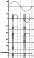
- FIG. 6 is a control pulse diagram of the totem-pole PFC circuit provided in FIG. 1 operating in a totem-pole PFC mode;
- FIG. 7 is a control pulse diagram of the totem-pole PFC circuit provided in FIG. 1 operating in the totem-pole voltage-doubler PFC mode;
- FIG. 8 is another control pulse diagram of the totem-pole PFC circuit provided in FIG. 1 operating in the totem-pole voltage doubler PFC mode;
- Fig. 9 is a kind of control pulse diagram that the totem pole PFC circuit provided by Fig. 2 operates in totem pole voltage doubler PFC mode;
- FIG. 10 is another control pulse diagram of the totem-pole PFC circuit provided in FIG. 2 operating in the totem-pole voltage doubler PFC mode;
- FIG. 11 is a schematic diagram of a current flow when the totem-pole PFC circuit according to an embodiment of the present invention enters a first state during a first preset time period;
- FIG. 12 is a schematic diagram of another current flow when the totem-pole PFC circuit according to an embodiment of the present invention enters a first state during a first preset time period;
- FIG. 13 is a schematic diagram of the current flow of the totem-pole PFC circuit that enters the second state during the first preset time period according to an embodiment of the present invention
- FIG. 14 is a schematic diagram of the current flow of the totem-pole PFC circuit that enters a fourth state during a first preset time period according to an embodiment of the present invention
- FIG. 15 is a schematic diagram of a current flow when the totem pole PFC circuit according to an embodiment of the present invention enters a fifth state during a second preset time period.
- Embodiments of the present invention provide a totem pole PFC circuit, a control method, a circuit board, an air conditioner and a computer storage medium, which can improve input current harmonics and power factor, and improve voltage conversion efficiency.
- FIG. 1 is a schematic structural diagram of a totem-pole PFC circuit provided by an embodiment of the first aspect of the present invention.
- the totem-pole PFC circuit includes a bridge circuit 100, a reactor L1, a bus capacitor module 200, a switch module 300, and a control Module 400.
- the bridge circuit 100 includes a first bridge arm and a second bridge arm connected in parallel with each other, the first bridge arm includes a first switch transistor Q1 and a second switch transistor Q2 connected in series, and the second bridge arm includes a third switch transistor connected in series with each other Q3 and the fourth switch tube Q4, the first switch tube Q1, the second switch tube Q2, the third switch tube Q3 and the fourth switch tube Q4 form a bridge circuit, wherein the first switch tube is connected in anti-parallel with a diode D1, A diode D2 is connected in anti-parallel to the second switch tube, a diode D3 is connected in anti-parallel to the third switch tube, and a diode D4 is connected in anti-parallel to the fourth switch tube;
- One end of the reactor L1 is connected to one end of the AC power source AC, the other end of the reactor L1 is connected to the connection point of the first switch tube Q1 and the second switch tube Q2, and the other end of the AC power source AC is connected to the third switch tube Q3 and the first switch tube Q3.
- the busbar capacitor module 200 includes a first capacitor C1 and a second capacitor C2, and the first capacitor C1 and the second capacitor C2 are connected in series to the output end of the bridge circuit 100 in parallel;
- One end of the switch module 300 is connected to the connection point of the third switch tube Q3 and the fourth switch tube Q4, and the other end of the switch module 300 is connected to the connection point of the first capacitor C1 and the second capacitor C2;
- the control module 400 is used to control the opening and closing of the switch module 300, and to control the turn-on and turn-off of the first switch tube Q1, the second switch tube Q2, the third switch tube Q3 and the fourth switch tube Q4, so that the Set a time period and a second preset time period to charge and discharge the reactor L1 multiple times; the first preset time period is located in the first half of the positive half cycle of the alternating current power supply AC, and the second preset time period is located in the negative side of the alternating current power supply AC. The first half of the half cycle.
- an embodiment of the present invention also provides another schematic structural diagram of a totem pole PFC circuit.
- it further includes a first bus diode D10 and a second bus diode D11 , and the anode of the first bus diode D10 is connected to To one end of the first bridge arm and one end of the second bridge arm, the cathode of the first busbar diode D10 is connected to one end of the busbar capacitor module 200; the anode of the second busbar diode D11 is connected to the other end of the busbar capacitor module 200, and the second The cathode of the bus diode D11 is connected to the other end of the first bridge arm and the other end of the second bridge arm.
- the first bus diode D10 and the second bus diode D11 are added, which restricts the current flow of the bus, and can prevent the electric energy stored in the bus capacitor module 200 from being released in reverse.
- the control module 400 controls the opening and closing of the switch module 300, so that the totem-pole PFC circuit can switch between the totem-pole PFC mode and the totem-pole voltage multiplier PFC mode.
- the switch module 300 When the switch module 300 is turned on, the totem-pole PFC circuit operates in the totem-pole PFC mode.
- the switch module 300 When the switch module 300 is closed, the totem-pole PFC circuit operates in the totem-pole voltage multiplier PFC mode.
- the totem pole PFC circuit further includes a current detection module 500 for detecting the AC current value Is input by the AC power supply, and the current detection module 500 is connected in series with the AC power supply AC and the power supply. Between the bridge circuits 100 , the output end of the current detection module 500 is connected to the control module 400 .
- the current detection module 500 may be composed of a current transformer and an external detection circuit. The current transformer may be connected in series with the live wire end or the neutral wire end of the AC power supply.
- the specific circuit of the current detection module 500 can refer to the prior art, which will not be repeated here. .
- the totem pole PFC circuit further includes a DC voltage detection module 600 , the DC voltage detection module 600 is connected in parallel with the output end of the bridge circuit 400 , and the output of the DC voltage detection module 600 The terminal is connected to the control module 400 .
- the DC voltage detection module 600 may be composed of a simple circuit based on a resistive voltage dividing structure, and the specific circuit may refer to the prior art, which will not be repeated here.
- the totem pole PFC circuit further includes an AC voltage detection module 700, the AC voltage detection module 700 is connected in parallel between the AC power source AC and the bridge circuit 100, and the output of the AC voltage detection module 700 is The terminal is connected to the control module 400 .
- the specific circuit of the AC voltage detection module 700 may refer to the prior art, and details are not repeated here.
- the switch module 300 should be selected as a bidirectional controllable high-frequency switch; for the totem-pole PFC circuit shown in FIG. 2, the switch module 300 may be a relay, a mechanical switch device or Bidirectional controllable high frequency switch.
- the bidirectionally controllable high-frequency switch may be one of the structures shown in FIGS. 3 to 5 .
- the switch module 300 shown in FIG. 3 includes a first diode D-1, a second diode D-2, a third diode D-3, a fourth diode D-4, and a fifth diode D-1.
- the switch tube Q5, the first diode D-1 and the second diode D-2 are connected in series to form the first branch of the diode, and the third diode D-3 and the fourth diode D-4 are connected in series to form a diode
- the second branch, the fifth switch tube Q5, the first branch of the diode and the second branch of the diode are connected in parallel with each other, and the connection point of the first diode D-1 and the second diode D-2 is drawn out as the switch module 300
- One end of the third diode D-3 and the connection point of the fourth diode D-4 is drawn out as the other end of the switch module 300 .
- the closed state of the switch module 300 corresponds to the conduction of the fifth switch tube Q5, and the disconnection of the switch module
- the switch module 300 shown in FIG. 4 includes a sixth switch transistor Q6 and a seventh switch transistor Q7 connected in antiparallel.
- the closing of the switch module 300 corresponds to the sixth switch transistor Q6 and the seventh switch transistor Q7 being turned on at the same time or the sixth switch transistor Q6 being turned on during the positive half cycle of the AC power supply AC, and the seventh switch tube Q6 being turned on during the negative half cycle of the AC power supply AC.
- the switch tube Q7 is turned on; the disconnection of the switch module 300 corresponds to the simultaneous turn-off of the sixth switch tube Q6 and the seventh switch tube Q7.
- the switch module 300 shown in FIG. 5 includes an eighth switch transistor Q8 and a ninth switch transistor Q9 connected in reverse series, the eighth switch transistor Q8 is connected in anti-parallel with an eighth diode D-8, and the ninth switch transistor Q9 is connected in reverse-parallel with an eighth diode D-8 The first diode D-9.
- the closing of the switch module 300 corresponds to the eighth switch transistor Q8 and the ninth switch transistor Q9 being turned on at the same time or the eighth switch transistor Q8 being turned on during the positive half cycle of the AC power supply AC, and the ninth switch tube Q8 being turned on during the negative half cycle of the AC power supply AC.
- the switch tube Q9 is turned on; the disconnection of the switch module 300 corresponds to the turn-off of the eighth switch tube Q8 and the ninth switch tube Q9 at the same time.
- the embodiment of the second aspect of the present invention provides a totem-pole PFC circuit control method, which is applicable to the totem-pole PFC circuit shown in FIG. 1 and FIG. 2 , and the control method includes the following steps:
- the control module 400 controls the opening and closing of the switch module 300, and controls the turn-on and turn-off of the first switch tube Q1, the second switch tube Q2, the third switch tube Q3 and the fourth switch tube Q4, so that the first preset time period is
- the reactor L1 is charged and discharged multiple times with the second preset time period; the first preset time period is located in the first half of the positive half cycle of the alternating current power supply AC, and the second preset time period is located in the negative half cycle of the alternating current power supply AC. first half.
- the control module 400 controls the opening and closing of the switch module 300, so that the totem-pole PFC circuit can switch between the totem-pole PFC mode and the totem-pole voltage multiplier PFC mode.
- the switch module 300 When the switch module 300 is turned on, the totem-pole PFC circuit runs In the totem-pole PFC mode, when the switch module 300 is closed, the totem-pole PFC circuit operates in the totem-pole voltage multiplier PFC mode; it controls the first switch Q1, the second switch Q2, the third switch Q3 and the fourth switch Q4.
- the reactor L1 is charged and discharged multiple times during the first preset time period and the second preset time period, thereby improving the waveform of the input current, improving the harmonics of the input current and the power factor.
- the first preset The time period is located in the first half of the positive half cycle of the AC power supply, and the second preset time period is located in the first half of the negative half cycle of the AC power supply, which can rapidly increase the current and improve the voltage conversion efficiency when the current is small.
- the first preset time period and the second preset time period start after a short time interval after the alternating current power supply AC passes through the zero-crossing point, and the time interval is generally 0-5 milliseconds.
- the control method is divided into two cases. The first is when the demanded voltage is less than twice the peak voltage of the AC power supply AC, and the second is when the demanded voltage is greater than or equal to the peak value of the AC power supply AC. twice the voltage.
- the control switch module 300 is turned off; at this time, the totem-pole PFC circuit operates in the totem-pole PFC mode:
- the control bridge circuit 100 alternately enters the first state and the second state, wherein the first state is to turn on the first switch Q1 and the third switch Q3, or turn on the second switch tube Q2 and the fourth switch tube Q4; the second state is to turn on the first switch tube Q1 and the fourth switch tube Q4;
- control bridge circuit 100 alternately enters the first state and the third state, wherein the third state is to turn on the third switch transistor Q3 and the second switch transistor Q2.
- the first switch Q1 and the third switch Q3 are turned on, or the second switch Q2 and the fourth switch Q4 are turned on; the second switch Q1 and the third switch Q3 are turned on; There is only one state: the first switch Q1 and the fourth switch Q4 are turned on.
- the first state is to turn on the first switch transistor Q1 and the third switch transistor Q3, the AC power source AC, the reactor L1, the first switch transistor Q1, and the third switch transistor Q1 are formed.
- the reactor charging circuit of the switch tube Q3 is shown by the dotted arrow in Figure 11; in the first preset time period, if the first state is the second switch tube Q2 and the fourth switch tube Q4, the AC power supply AC,
- the reactor charging circuit of the reactor L1, the second switch tube Q2, and the fourth switch tube Q4 is shown by the dashed arrow in FIG. 12; in the first preset time period, the second state turns on the first switch tube Q1 and the first switch tube Q1 and the first switch tube Q1.
- Four switches Q4 the current of the reactor L1 forms a discharge loop through the first switch Q1, the first capacitor C1, the second capacitor C2, and the fourth switch Q4 to charge the bus capacitor module 200, as shown by the dashed arrow in FIG. 13 . It can be known from the same principle that the current flows in various situations in the second preset time period, and will not be repeated here.
- the first state is preferably the case where the second switch tube Q2 and the fourth switch tube Q4 are turned on, so that the fourth switch tube Q4 is always turned on during the first preset time period, and there is no need to perform switching, as shown in the positive half cycle of Figure 6.
- the second preset time period there are also two situations in the first state, and there is only one situation in the third state: the third switching transistor Q3 and the second switching transistor Q2 are turned on, so the first state is preferably turned on.
- the first switch transistor Q1 and the third switch transistor Q3 are turned on, so that the third switch transistor Q3 remains on during the second preset time period without switching, as shown in the negative half cycle of FIG. 6 .
- the control bridge circuit 100 alternately enters the first state and the fourth state, wherein , the first state is to turn on the first switch tube Q1 and the third switch tube Q3, or turn on the second switch tube Q2 and the fourth switch tube Q4; the fourth state is to turn on the first switch tube Q1 and close the switch module 300 ;
- the control bridge circuit 100 alternately enters the first state and the fifth state, wherein the fifth state is to close the switch module 300 and turn on the second switch tube Q2.
- the current flow of the bridge circuit 100 entering the first state can refer to FIG. 11 and FIG. 12 for the same reason.
- the bridge circuit 100 enters the fourth state, turning on the first switch transistor Q1 and closing the switch module. 300, the current of the reactor L1 forms a discharge loop through the first switch tube Q1, the first capacitor C1, and the switch module 300 to charge the first capacitor C1, as shown by the dotted arrow in FIG.
- the bridge circuit 100 enters the fifth state, closes the switch module 300 and turns on the second switch tube Q2, the current of the reactor L1 forms a discharge loop through the switch module 300, the second capacitor C2, and the second switch tube Q2, and supplies the second capacitor C2 charges, as indicated by the dashed arrow in Figure 15.
- the first switch transistor Q1 and the third switch transistor Q3 are turned on, or the second switch transistor Q2 and the fourth switch transistor Q4 are turned on; the fourth state There is only one case: the first switch transistor Q1 is turned on and the switch module 300 is closed. If the second switch Q2 and the fourth switch Q4 are selected to be turned on in the first state, the third switch Q3 can be kept off for the first preset time period, as shown in the positive half cycle of FIG.
- the state selection turns on the first switch transistor Q1 and the third switch transistor Q3, so that the second switch transistor Q2 and the fourth switch transistor Q4 can be kept off during the first preset time period, and the first switch transistor Q1 can be kept in the first preset time period.
- the time period remains on, as shown in the positive half cycle of Figure 8.
- the second preset time period there are two situations in the first state, and there is only one situation in the fifth state, which is to close the switch module 300 and turn on the second switch transistor Q2.
- the fourth switch transistor Q4 can be kept off during the second preset time period, as shown in the negative half cycle of FIG. 7 ; if the first switch transistor Q4 is turned off
- the state selects to turn on the second switch Q2 and the fourth switch Q4, so that the first switch Q1 and the third switch Q3 can be kept off during the second preset time period, and the second switch Q2 can be turned off at the second preset time. The period remains on, as shown in the negative half cycle of Figure 8.
- the switch module 300 needs to be controlled to be disconnected, see the waveform diagrams of the switch module 300 in FIG. 7 and FIG. 8 .
- the switch module 300 is controlled to be disconnected, which can prevent the electric energy stored in the bus capacitor module 200 from being released in reverse.
- the control method is also divided into two cases. twice the peak voltage.
- the control method corresponding to the first situation in FIG. 2 is the same as the control method corresponding to the first situation in FIG. 1 , and the description will not be repeated here.
- the control method corresponding to the second situation in FIG. 2 is basically the same as the control method corresponding to the second situation in FIG. 1 , the only difference is that the second situation in FIG.
- the switch module 300 is disconnected. In the second case in FIG. 2 , in the first state, there is no need to control the switch module 300 to be disconnected, and the switch module 300 can be controlled to remain closed, as shown in FIGS. 9 and 10 .
- the number of times of charging and discharging the reactor L1 is determined according to the magnitude of the load, which includes but is not limited to input current, bus voltage, compressor current, compressor frequency, and the like.
- the load includes but is not limited to input current, bus voltage, compressor current, compressor frequency, and the like.
- the circuit board of the embodiment of the third aspect of the present invention includes the totem-pole PFC circuit of the embodiment of the first aspect of the present invention.
- the circuit board of this embodiment carries the totem-pole PFC circuit according to the first aspect of the present invention, and its function and working principle are based on the above-mentioned totem-pole PFC circuit. Therefore, the circuit board of this embodiment has the same characteristics as the above-mentioned totem-pole PFC circuit. The effect, in order to save space, will not be repeated here.
- the air conditioner according to the embodiment of the fourth aspect of the present invention includes the circuit board according to the embodiment of the third aspect of the present invention. or,
- the memory stores instructions executable by the at least one processor, the instructions being executed by the at least one processor to enable the at least one processor to perform operations according to the present invention
- the air conditioner of this embodiment includes the circuit board of the third aspect of the present invention, and its function and working principle are based on the above circuit board. Therefore, the air conditioner of this embodiment has the same effect as the above circuit board. In order to save space, The description will not be repeated here.
- a computer-readable storage medium is characterized in that the computer-readable storage medium stores computer-executable instructions, and the computer-executable instructions are used to cause a computer to execute the embodiment according to the second aspect of the present invention.
- the totem pole PFC circuit control method is characterized in that the computer-readable storage medium stores computer-executable instructions, and the computer-executable instructions are used to cause a computer to execute the embodiment according to the second aspect of the present invention.
- the computer storage medium of this embodiment executes the totem-pole PFC circuit control method of the second aspect of the present invention. Therefore, the computer storage medium of this embodiment has the same function as the totem-pole PFC circuit control method described above. To save space, here The description will not be repeated.
- Computer storage media include, but are not limited to, RAM, ROM, EEPROM, flash memory or other memory technology, CD-ROM, digital versatile disk (DVD) or other optical disk storage, magnetic cartridges, magnetic tape, magnetic disk storage or other magnetic storage devices, or may Any other medium used to store desired information and which can be accessed by a computer.
- communication media typically embodies computer readable instructions, data structures, program modules, or other data in a modulated data signal such as a carrier wave or other transport mechanism, and can include any information delivery media, as is well known to those of ordinary skill in the art .
Landscapes
- Engineering & Computer Science (AREA)
- Power Engineering (AREA)
- Rectifiers (AREA)
Abstract
一种图腾柱PFC电路、控制方法、线路板及空调器。该图腾柱PFC电路包括电桥电路(100)、电抗器(L1)、母线电容模块(200)、开关模块(300)和控制模块(400),控制模块(400)控制开关模块(300)的开合,并控制第一开关管(Q1)、第二开关管(Q2)、第三开关管(Q3)和第四开关管(Q4)的导通截止,以在第一预设时间段和第二预设时间段对电抗器(L1)进行多次充放电。
Description
相关申请的交叉引用
本申请要求于2020年7月22日提交的申请号为202010711470.4、名称为“图腾柱PFC电路、控制方法、线路板及空调器”的中国专利申请的优先权,其全部内容通过引用并入本申请。
本发明涉及空调器技术领域,特别涉及一种图腾柱PFC电路、控制方法、线路板及空调器。
现有的图腾柱PFC电路和倍压电路都是很常用的电流拓扑结构。其中图腾柱PFC拓扑可以将整流的电压进行升压,倍压电路能够将整流电路输出的电压进行翻倍,但不能升压,两种电路拓扑都有各自的优点。若是简单将两种电路结合,又会导致系统的导通损耗大,谐波含量高,电压转换效率低。
发明内容
本发明的目的在于至少解决现有技术中存在的技术问题之一,提供一种图腾柱PFC电路、控制方法、线路板及空调器,能够改善输入电流谐波和功率因数,提高电压转换效率。
根据本发明第一方面实施例图腾柱PFC电路,包括:
电桥电路,所述电桥电路包括相互并联的第一桥臂和第二桥臂,所述第一桥臂包括相互串联的第一开关管和第二开关管,所述第二桥臂包括相互串联的第三开关管和第四开关管;
电抗器,所述电抗器的一端连接交流电源的一端,所述电抗器的另一端连接至所述第一开关管和所述第二开关管的连接点,交流电源的另一端连接至所述第三开关管和所述第四开关管的连接点;
母线电容模块,所述母线电容模块包括第一电容和第二电容,所述第一电容和所述第二电容串联后并联在所述电桥电路的输出端;
开关模块,所述开关模块的一端连接至所述第三开关管和所述第四开关管的连接点,所述开关模块的另一端连接至所述第一电容和所述第二电容的连接点;
控制模块,用于控制所述开关模块的开合、以及控制所述第一开关管、所述第二开关管、所述第三开关管和所述第四开关管的导通截止,以使在第一预设时间段和第二预设时间段对所述电抗器进行多次充放电;所述第一预设时间段位于交流电源的正半周期的前半段,所述第二预设时间段位于交流电源的负半周期的前半段。
根据本发明实施例的图腾柱PFC电路,至少具有如下有益效果:控制模块控制开关模块的开合,使得图腾柱PFC电路能够在图腾柱PFC模式和图腾柱倍压PFC模式之间切换,开关模块打开时,图腾柱PFC电路运行于图腾柱PFC模式,开关模块闭合时,图腾柱PFC电路运行于图腾柱倍压PFC模式;控制第一开关管、第二开关管、第三开关管和第四开关管的导通截止,以使在第一预设时间段和第二预设时间段对电抗器进行多次充放电,从而改善输入电流的波形,改善输入电流谐波和功率因数,第一预设时间段位于交流电源的正半周期的前半段,第二预设时间段位于交流电源的负半周期的前半段,能够在电流较小时快速提升电流,提高电压转换效率。
根据本发明的一些实施例,还包括第一母线二极管和第二母线二极管,所述第一母线二极管的正极连接至所述第一桥臂的一端以及所述第二桥臂的一端,所述第一母线二极管的负极连接至所述母线电容模块的一端;所述第二母线二极管的正极连接至所述母线电容模块的另一端,所述第二母线二极管的负极连接至所述第一桥臂的另一端以及所述第二桥臂的另一端。
在本实施例中,增加了第一母线二极管和第二母线二极管,限制了母线的电流流向,能够避免母线电容模块中存储的电能反向释放。
根据本发明的一些实施例,还包括用于检测交流电源输入的交流电流值的电流检测模块,所述电流检测模块串联在交流电源和所述电桥电路之间,所述电流检测模块的输出端连接所述控制模块。交流电压检测模块将检测到的交流电压值从输出端传输给控制模块,以便控制模块根据交流电压值进行控制调整。
根据本发明的一些实施例,还包括直流电压检测模块,所述直流电压检测模块并联在所述母线电容模块的后端,所述直流电压检测模块的输出端连接所述控制模块。直流电压检测模块将检测到的直流母线电压值从输出端传输给控制模块,以便控制模块根据直流母线电压值进行控制调整。
根据本发明的一些实施例,还包括交流电压检测模块,所述交流电压检测模块并联在交流电源和所述电桥电路之间,所述交流电压检测模块的输出端连接所述控制模块。交流电压检测模块将检测到的交流电压值从输出端传输给控制模块,以便控制模块根据交流电压值进行控制调整。
根据本发明的一些实施例,所述开关模块包括第一二极管、第二二极管、第三二极管、第四二极管和第五开关管,所述第一二极管和所述第二二极管串联形成二极管第一支路,所述第三二极管和所述第四二极管相互串联形成二极管第二支路,所述第五开关管、所述二极管第一支路和所述二极管第二支路相互并联,所述第一二极管和所述第二二极管的连接点引出作为所述开关模块的一端,所述第三二极管和所述第四二极管的连接点引出作为所述开关模块的另一端。本实施例给出了开关模块的一种具体电路结构,开关模块的闭合状态对应于第五开关管导通,开关模块的断开对应于第五开关管截止。
根据本发明的一些实施例,所述开关模块包括反向并联的第六开关管和第七开关管。本实施例给出了开关模块的另一种具体电路结构,开关模块的闭合状态对应于第六开关管和第七开关管同时导通或者在交流电源的正半周期第六开关管导通,在交流电源的负半周期第七开关管导通;开关模块的断开对应于第六开关管和第七开关管同时截止。
根据本发明的一些实施例,所述开关模块包括反向串联的第八开关管和第九开关管,所述第八开关管和所述第九开关管均反并联有二极管。本实施例给出了开关模块的又一种具体电路结构,开关模块的闭合对应于第八开关管和第九开关管同时导通或者在交流电源的正半周期第八开关管导通,在交流电源的负半周期第九开关管导通;开关模块的断开对应于第八开关管和第九开关管同时截止。
根据本发明的一些实施例,所述开关模块为继电器或者机械开关器件。开关模块除了可以采用上述实施例提供的三种双向可控的高频开关,还可以采用本实施例给出的两种实施例方式。
根据本发明第二方面实施例的图腾柱PFC电路控制方法,所述图腾柱PFC电路包括:
电桥电路,所述电桥电路包括相互并联的第一桥臂和第二桥臂,所述第一桥臂包括相互串联的第一开关管和第二开关管,所述第二桥臂包括相互串联的第三开关管和第四开关管;
电抗器,所述电抗器的一端连接交流电源的一端,所述电抗器的另一端连接至所述第一开关管和所述第二开关管的连接点,交流电源的另一端连接至所述第三开关管和所述第四开关管的连接点;
母线电容模块,所述母线电容模块包括第一电容和第二电容,所述第一电容和所述第二电容串联后并联在所述电桥电路的输出端;
开关模块,所述开关模块的一端连接至所述第三开关管和所述第四开关管的连接点,所述开关模块的另一端连接至所述第一电容和所述第二电容的连接点;
控制模块,分别与所述电桥电路和所述开关模块连接;
所述方法包括:
所述控制模块控制所述开关模块的开合、以及控制所述第一开关管、所述第二开关管、所述第三开关管和所述第四开关管的导通截止,以使在第一预设时间段和第二预设时间段对所述电抗器进行多次充放电;所述第一预设时间段位于交流电源的正半周期的前半段,所述第二预设时间段位于交流电源的负半周期的前半段。
根据本发明实施例的图腾柱PFC电路控制方法,至少具有如下有益效果:控制模块控制开关模块的开合,使得图腾柱PFC电路能够在图腾柱PFC模式和图腾柱倍压PFC模式之间切换,开关模块打开时,图腾柱PFC电路运行于图腾柱PFC模式,开关模块闭合时,图腾柱PFC电路运行于图腾柱倍压PFC模式;控制第一开关管、第二开关管、第三开关管和第四开关管的导通截止,以使在第一预设时间段和第二预设时间段对电抗器进行多次充放电,从而改善输入电流的波形,改善输入电流谐波和功率因数,第一预设时间段位于交流电源的正半周期的前半段,第二预设 时间段位于交流电源的负半周期的前半段,能够在电流较小时快速提升电流,提高电压转换效率。
根据本发明的一些实施例,所述的控制所述开关模块的开合、以及控制所述第一开关管、所述第二开关管、所述第三开关管和所述第四开关管的导通截止,以使在第一预设时间段和第二预设时间段对所述电抗器进行多次充放电,包括:
在需求电压小于交流电源的峰值电压的两倍的情况下,控制所述开关模块断开;
在第一预设时间段内,控制所述电桥电路交替进入第一状态和第二状态,其中,所述第一状态为导通所述第一开关管和所述第三开关管,或者导通所述第二开关管和所述第四开关管;所述第二状态为导通所述第一开关管和所述第四开关管;
在第二预设时间段内,控制所述电桥电路交替进入第一状态和第三状态,其中,所述第三状态为导通所述第三开关管和所述第二开关管。
在本实施例中,若需求电压小于交流电源的峰值电压的两倍,此时控制所述开关模块断开,图腾柱PFC电路运行于图腾柱PFC模式;在第一预设时间段内,电桥电路进入第一状态时,第一开关管和第三开关管导通,或者第二开关管和第四开关管,形成了交流电源、电抗器、第一开关管、第三开关管的电抗器充电回路,或者形成了交流电源、电抗器、第二开关管、第四开关管的电抗器充电回路;电桥电路进入第二状态时,第一开关管和第四开关管导通,电抗器的电流通过第一开关管、第一电容、第二电容、第四开关管形成放电回路,给母线电容模块充电;在第一预设时间段内电桥电路交替进入第一状态和第二状态,实现对电抗器进行多次充放电;同理,在第二预设时间段内,电桥电路进入第一状态时,第一开关管和第三开关管导通,或者第二开关管和第四开关管,形成了交流电源、电抗器、第一开关管、第三开关管的电抗器充电回路,或者形成了交流电源、电抗器、第二开关管、第四开关管的电抗器充电回路;电桥电路进入第三状态时,第三开关管和第二开关管导通,电抗器的电流通过第三开关管、第一电容、第二电容、第二开关管形成放电回路,给母线电容模块充电;在第二预设时间段内电桥电路交替进入第一状态和第三状态,实现对电抗器进行多次充放电。
根据本发明的一些实施例,所述的控制所述开关模块的开合、以及控制所述第一开关管、所述第二开关管、所述第三开关管和所述第四开关管的导通截止,以使在第一预设时间段和第二预设时间段对所述电抗器进行多次充放电,包括:
在需求电压大于或者等于交流电源的峰值电压的两倍的情况下,在第一预设时间段内,控制所述电桥电路交替进入第一状态和第四状态,其中,所述第一状态为导通所述第一开关管和所述第三开关管,或者导通所述第二开关管和所述第四开关管;所述第四状态为导通所述第一开关管和闭合所述开关模块;在第二预设时间段内,控制所述电桥电路交替进入第一状态和第五状态,其中所述第五状态为闭合所述开关模块和导通所述第二开关管。
在本实施例中,电桥电路进入第一状态时,第一开关管和第三开关管导通,或者第二开关管和第四开关管,形成了交流电源、电抗器、第一开关管、第三开关管的电抗器充电回路,或者形成了交流电源、电抗器、第二开关管、第四开关管的电抗器充电回路;电桥电路进入第四状态时,第一开关管导通和开关模块闭合,电抗器的电流通过第一开关管、第一电容、开关模块形成放电回路,给第一电容充电;在第一预设时间段内电桥电路交替进入第一状态和第四状态,实现对电抗器进行多次充放电;电桥电路进入第五状态时,开关模块闭合和第二开关管导通,电抗器的电流通过开关模块、第二电容、第二开关管形成放电回路,给第二电容充电;在第二预设时间段内电桥电路交替进入第一状态和第五状态,实现对电抗器进行多次充放电。
根据本发明的一些实施例,在第一状态下,控制所述开关模块断开。在第一状态下控制开关模块断开,可以避免电抗器充电回路对电抗器充电时,母线电容模块中存储的电能反向释放。
根据本发明的一些实施例,所述图腾柱PFC电路还包括第一母线二极管和第二母线二极管,所述第一母线二极管的正极连接至所述第一桥臂的一端以及所述第二桥臂的一端,所述第一母线二极管的负极连接至所述母线电容模块的一端;所述第二母线二极管的正极连接至所述母线电容模块的另一端,所述第二母线二极管的负极连接至所述第一桥臂的另一端以及所述第二桥臂的另一端;
所述的控制所述开关模块的开合、以及控制所述第一开关管、所述第二开关管、所述第三开关管和所述第四开关管的导通截止,以使在第一预设时间段和第二预设时间段对所述电抗器进行多次充放电,包括:
在需求电压大于或者等于交流电源的峰值电压的两倍的情况下,控制所述开关模块闭合;
在第一预设时间段内,控制所述电桥电路交替进入第一状态和第四状态,其中,所述第一状态为导通所述第一开关管和所述第三开关管,或者导通所述第二开关管和所述第四开关管;所述第四状态为导通所述第一开关管和闭合所述开关模块;
在第二预设时间段内,控制所述电桥电路交替进入第一状态和第五状态,其中所述第五状态为闭合所述开关模块和导通所述第二开关管。
同理,在本实施例中,电桥电路进入第一状态时,第一开关管和第三开关管导通,或者第二开关管和第四开关管,形成了交流电源、电抗器、第一开关管、第三开关管的电抗器充电回路,或者形成了交流电源、电抗器、第二开关管、第四开关管的电抗器充电回路;电桥电路进入第四状态时,第一开关管导通和开关模块闭合,电抗器的电流通过第一开关管、第一电容、开关模块形成放电回路,给第一电容充电;在第一预设时间段内电桥电路交替进入第一状态和第四状态,实现对电抗器进行多次充放电;电桥电路进入第五状态时,开关模块闭合和第二开关管导通,电抗器的电流通过开关模块、第二电容、第二开关管形成放电回路,给第二电容充电;在第二预设时间段内电桥电路交替进入第一状态和第五状态,实现对电抗器进行多次充放电。另外,由于在本实施例中,增加了第一母线二极管和第二母线二极管,限制了母线的电流流向,能够避免母线电容模块中存储的电能反向释放,因此在电桥电路进入第一状态时,无需控制开关模块断开,开关模块可以一直保持闭合状态,从而减少了开关模块频繁切换带来的损耗。
根据本发明的一些实施例,还包括以下步骤:
在所述母线电容模块的负载量增大的情况下,增加在第一预设时间段和第二预设时间段对所述电抗器进行充放电的次数;
在所述母线电容模块的负载量减少的情况下,减小在第一预设时间段和第二预设时间段对所述电抗器进行充放电的次数。
在本实施例中,由于对电抗器进行充放电的次数,开关的次数也就越多,开关损耗也越大,因此在满足谐波要求的前提下,尽量减少开关损耗。对电抗器进行充放电的次数根据负载量的大小来进行确定,负载量包括但不限于输入电流、母线电压、压缩机电流、压缩机频率等。当负载量大时,增加对电抗器进行充放电的次数,当负载量小时,减小对电抗器进行充放电的次数,既能满足需求,又能减少损耗。
根据本发明第三方面实施例的线路板,包括根据本发明第一方面实施例所述的图腾柱PFC电路。
根据本发明实施例的线路板,至少具有如下有益效果:控制模块控制开关模块的开合,使得图腾柱PFC电路能够在图腾柱PFC模式和图腾柱倍压PFC模式之间切换,开关模块打开时,图腾柱PFC电路运行于图腾柱PFC模式,开关模块闭合时,图腾柱PFC电路运行于图腾柱倍压PFC模式;控制第一开关管、第二开关管、第三开关管和第四开关管的导通截止,以使在第一预设时间段和第二预设时间段对电抗器进行多次充放电,从而改善输入电流的波形,改善输入电流谐波和功率因数,第一预设时间段位于交流电源的正半周期的前半段,第二预设时间段位于交流电源的负半周期的前半段,能够在电流较小时快速提升电流,提高电压转换效率。
根据本发明第四方面实施例的空调器,包括根据本发明第三方面实施例所述的线路板;或者,
包括至少一个处理器和用于与所述至少一个处理器通信连接的存储器;所述存储器存储有能够被所述至少一个处理器执行的指令,所述指令被所述至少一个处理器执行,以使所述至少一个处理器能够执行根据本发明第二方面实施例所述的图腾柱PFC电路控制方法。
根据本发明实施例的空调器,至少具有如下有益效果:控制模块控制开关模块的开合,使得图腾柱PFC电路能够在图腾柱PFC模式和图腾柱倍压PFC模式之间切换,开关模块打开时,图腾柱PFC电路运行于图腾柱PFC模式,开关模块闭合时,图腾柱PFC电路运行于图腾柱倍压PFC模式;控制第一开关管、第二开关管、第三开关管和第四 开关管的导通截止,以使在第一预设时间段和第二预设时间段对电抗器进行多次充放电,从而改善输入电流的波形,改善输入电流谐波和功率因数,第一预设时间段位于交流电源的正半周期的前半段,第二预设时间段位于交流电源的负半周期的前半段,能够在电流较小时快速提升电流,提高电压转换效率。
根据本发明第五方面实施例的一种计算机可读存储介质,其特征在于,所述计算机可读存储介质存储有计算机可执行指令,所述计算机可执行指令用于使计算机执行根据本发明第二方面实施例所述的图腾柱PFC电路控制方法。
本发明的附加方面和优点将在下面的描述中部分给出,部分将从下面的描述中变得明显,或通过本发明的实践了解到。
下面结合附图和实施例对本发明进一步地说明;
图1为本发明实施例提供的图腾柱PFC电路的电路原理图;
图2为本发明实施例提供的另一图腾柱PFC电路的电路原理图;
图3为本发明实施例提供的图腾柱PFC电路的开关模块的电路原理图;
图4为本发明实施例提供的图腾柱PFC电路的开关模块的另一电路原理图;
图5为本发明实施例提供的图腾柱PFC电路的开关模块的又一电路原理图;
图6为图1提供的图腾柱PFC电路运行于图腾柱PFC模式的控制脉冲图;
图7为图1提供的图腾柱PFC电路运行于图腾柱倍压PFC模式的一种控制脉冲图;
图8为图1提供的图腾柱PFC电路运行于图腾柱倍压PFC模式的另一种控制脉冲图;
图9为图2提供的图腾柱PFC电路运行于图腾柱倍压PFC模式的一种控制脉冲图;
图10为图2提供的图腾柱PFC电路运行于图腾柱倍压PFC模式的另一种控制脉冲图;
图11为本发明实施例提供的图腾柱PFC电路在第一预设时间段进入第一状态的一种电流流向示意图;
图12为本发明实施例提供的图腾柱PFC电路在第一预设时间段进入第一状态的另一种电流流向示意图;
图13为本发明实施例提供的图腾柱PFC电路在第一预设时间段进入第二状态的电流流向示意图;
图14为本发明实施例提供的图腾柱PFC电路在第一预设时间段进入第四状态的电流流向示意图;
图15为本发明实施例提供的图腾柱PFC电路在第二预设时间段进入第五状态的电流流向示意图。
本部分将详细描述本发明的具体实施例,本发明之较佳实施例在附图中示出,附图的作用在于用图形补充说明书文字部分的描述,使人能够直观地、形象地理解本发明的每个技术特征和整体技术方案,但其不能理解为对本发明保护范围的限制。
在本发明的描述中,如果有描述到第一、第二只是用于区分技术特征为目的,而不能理解为指示或暗示相对重要性或者隐含指明所指示的技术特征的数量或者隐含指明所指示的技术特征的先后关系。
本发明的描述中,除非另有明确的限定,设置、安装、连接等词语应做广义理解,所属技术领域技术人员可以结合技术方案的具体内容合理确定上述词语在本发明中的具体含义。
本发明实施例提供一种图腾柱PFC电路、控制方法、线路板、空调器及计算机存储介质,能够改善输入电流谐波和功率因数,提高电压转换效率。
下面结合附图,对本发明实施例作进一步阐述。
如图1所示,图1是本发明第一方面实施例提供的图腾柱PFC电路的结构示意图,图腾柱PFC电路包括电桥电路100、电抗器L1、母线电容模块200、开关模块300和控制模块400。
电桥电路100包括相互并联的第一桥臂和第二桥臂,第一桥臂包括相互串联的第一开关管Q1和第二开关管Q2,第二桥臂包括相互串联的第三开关管Q3和第四开关管Q4,第一开关管Q1、第二开关管Q2、第三开关管Q3和第四开关管Q4组成了一个桥式电路,其中,第一开关管反并联有二极管D1,第二开关管反并联有二极管D2,第三开关管反并联有二极管D3,第四开关管反并联有二极管D4;
电抗器L1的一端连接交流电源AC的一端,电抗器L1的另一端连接至第一开关管Q1和第二开关管Q2的连接点,交流电源AC的另一端连接至第三开关管Q3和第四开关管Q4的连接点;
母线电容模块200包括第一电容C1和第二电容C2,第一电容C1和第二电容C2串联后并联在电桥电路100的输出端;
开关模块300,的一端连接至第三开关管Q3和第四开关管Q4的连接点,开关模块300的另一端连接至第一电容C1和第二电容C2的连接点;
控制模块400,用于控制开关模块300的开合、以及控制第一开关管Q1、第二开关管Q2、第三开关管Q3和第四开关管Q4的导通截止,以使在第一预设时间段和第二预设时间段对电抗器L1进行多次充放电;第一预设时间段位于交流电源AC的正半周期的前半段,第二预设时间段位于交流电源AC的负半周期的前半段。
参照图2,本发明实施例还提供图腾柱PFC电路的另一种结构示意图,在图1的基础上,还包括第一母线二极管D10和第二母线二极管D11,第一母线二极管D10的正极连接至第一桥臂的一端以及第二桥臂的一端,第一母线二极管D10的负极连接至母线电容模块200的一端;第二母线二极管D11的正极连接至母线电容模块200的另一端,第二母线二极管D11的负极连接至第一桥臂的另一端以及第二桥臂的另一端。在本实施例中增加了第一母线二极管D10和第二母线二极管D11,限制了母线的电流流向,能够避免母线电容模块200中存储的电能反向释放。
控制模块400控制开关模块300的开合,使得图腾柱PFC电路能够在图腾柱PFC模式和图腾柱倍压PFC模式之间切换,开关模块300打开时,图腾柱PFC电路运行于图腾柱PFC模式,开关模块300闭合时,图腾柱PFC电路运行于图腾柱倍压PFC模式。
参照图1和图2,在本发明的一些实施例中,图腾柱PFC电路还包括用于检测交流电源输入的交流电流值Is的电流检测模块500,电流检测模块500串联在交流电源AC和电桥电路100之间,电流检测模块500的输出端连接控制模块400。电流检测模块500可以由电流互感器和外加检测电路构成,电流互感器可以串联在交流电源AC的火线端或者零线端,电流检测模块500的具体电路可以参考现有技术,此处不再赘述。
参照图1和图2,在本发明的一些实施例中,图腾柱PFC电路还包括直流电压检测模块600,直流电压检测模块600并联在电桥电路400的输出端,直流电压检测模块600的输出端连接控制模块400。直流电压检测模块600可以采用基于电阻分压结构形式的简单电路组成,具体电路可参考现有技术,此处不再赘述。
参照图1,在本发明的一些实施例中,图腾柱PFC电路还包括交流电压检测模块700,交流电压检测模块700并联在交流电源AC和电桥电路100之间,交流电压检测模块700的输出端连接控制模块400。交流电压检测模块700的具体电路同理可参考现有技术,此处不再赘述。
进一步地,对于图1所示的图腾柱PFC电路,开关模块300应选择为双向可控的高频开关;对于图2所示的图腾柱PFC电路,开关模块300可以为继电器、机械开关器件或者双向可控的高频开关。其中,双向可控的高频开关可以是图3至图5所示的结构中的一种。
具体地,图3中展示的开关模块300包括第一二极管D‐1、第二二极管D‐2、第三二极管D‐3、第四二极管D‐4和第五开关管Q5,第一二极管D‐1和第二二极管D‐2串联形成二极管第一支路,第三二极管D‐3和第四二极管D‐4相互串联形成二极管第二支路,第五开关管Q5、二极管第一支路和二极管第二支路相互并联,第一二极管D‐1和第二二极管D‐2的连接点引出作为开关模块300的一端,第三二极管D‐3和第四二极管D‐4的连接点引出作为开关模块300的另一端。其中,开关模块300的闭合状态对应于第五开关管Q5导通,开关模块300的断开对应于第五开关管Q5截止。
图4中展示的开关模块300包括反向并联的第六开关管Q6和第七开关管Q7。其中,开关模块300的闭合对应于第六开关管Q6和第七开关管Q7同时导通或者在交流电源AC的正半周期第六开关管Q6导通,在交流电源AC的负半周期第七开关管Q7导通;开关模块300的断开对应于第六开关管Q6和第七开关管Q7同时截止。
图5中展示的开关模块300包括反向串联的第八开关管Q8和第九开关管Q9,第八开关管Q8反并联有第八二极管D‐8,第九开关管Q9反并联有第就二极管D‐9。其中,开关模块300的闭合对应于第八开关管Q8和第九开关 管Q9同时导通或者在交流电源AC的正半周期第八开关管Q8导通,在交流电源AC的负半周期第九开关管Q9导通;开关模块300的断开对应于第八开关管Q8和第九开关管Q9同时截止。
本发明的第二方面实施例提供一种图腾柱PFC电路控制方法,适用于图1和图2所示的图腾柱PFC电路,控制方法包括以下步骤:
控制模块400控制开关模块300的开合、以及控制第一开关管Q1、第二开关管Q2、第三开关管Q3和第四开关管Q4的导通截止,以使在第一预设时间段和第二预设时间段对电抗器L1进行多次充放电;第一预设时间段位于交流电源AC的正半周期的前半段,第二预设时间段位于交流电源AC的负半周期的前半段。
在本实施例中,控制模块400控制开关模块300的开合,使得图腾柱PFC电路能够在图腾柱PFC模式和图腾柱倍压PFC模式之间切换,开关模块300打开时,图腾柱PFC电路运行于图腾柱PFC模式,开关模块300闭合时,图腾柱PFC电路运行于图腾柱倍压PFC模式;控制第一开关管Q1、第二开关管Q2、第三开关管Q3和第四开关管Q4的导通截止,以使在第一预设时间段和第二预设时间段对电抗器L1进行多次充放电,从而改善输入电流的波形,改善输入电流谐波和功率因数,第一预设时间段位于交流电源的正半周期的前半段,第二预设时间段位于交流电源的负半周期的前半段,能够在电流较小时快速提升电流,提高电压转换效率。其中,第一预设时间段和第二预设时间段开始于交流电源AC经过过零点之后的一个短暂时间间隔之后,该时间间隔一般为0‐5毫秒。
另外,由于图1的图腾柱PFC电路和图2的图腾柱PFC电路在结构上略有不同,因此在具体控制方法上也是有所差异,下面分别阐述两种不同结构的图腾柱PFC电路的具体控制方法。
对于图1的图腾柱PFC电路,其控制方法具体分为两种情况,第一种为需求电压小于交流电源AC的峰值电压的两倍,第二种为需求电压大于或者等于交流电源AC的峰值电压的两倍的情况下。
对于第一种情况,在需求电压小于交流电源AC的峰值电压的两倍的情况下,控制开关模块300断开;此时,图腾柱PFC电路运行于图腾柱PFC模式:
在第一预设时间段内,控制电桥电路100交替进入第一状态和第二状态,其中,第一状态为导通第一开关管Q1和第三开关管Q3,或者导通第二开关管Q2和第四开关管Q4;第二状态为导通第一开关管Q1和第四开关管Q4;
在第二预设时间段内,控制电桥电路100交替进入第一状态和第三状态,其中,第三状态为导通第三开关管Q3和第二开关管Q2。
其中,在第一预设时间段内,第一状态有两种情况:导通第一开关管Q1和第三开关管Q3,或者导通第二开关管Q2和第四开关管Q4;第二状态只有一种情况:导通第一开关管Q1和第四开关管Q4。具体地,在第一预设时间段内,若第一状态为导通第一开关管Q1和第三开关管Q3,则形成了交流电源AC、电抗器L1、第一开关管Q1、第三开关管Q3的电抗器充电回路,如图11虚线箭头所示;在第一预设时间段内,若第一状态为第二开关管Q2和第四开关管Q4,则形成了交流电源AC、电抗器L1、第二开关管Q2、第四开关管Q4的电抗器充电回路,如图12虚线箭头所示;在第一预设时间段内,第二状态导通第一开关管Q1和第四开关管Q4,电抗器L1的电流通过第一开关管Q1、第一电容C1、第二电容C2、第四开关管Q4形成放电回路,给母线电容模块200充电,如图13虚线箭头所示。在第二预设时间段内各种情况的电流流向同理可知,此处不再重复。
为了减少开关管的切换,第一状态优选为导通第二开关管Q2和第四开关管Q4的情况,从而使得在第一预设时间段内第四开关管Q4一直保持导通,无需进行切换,如图6的正半周期所示。同理,在第二预设时间段内,第一状态也是有两种情况,第三状态只有一种情况:导通第三开关管Q3和第二开关管Q2,因此第一状态优选为导通第一开关管Q1和第三开关管Q3的情况,从而使得在第二预设时间段内第三开关管Q3一直保持导通,无需进行切换,如图6的负半周期所示。
对于第二种情况,在需求电压大于或者等于交流电源AC的峰值电压的两倍的情况下,在第一预设时间段内,控制电桥电路100交替进入第一状态和第四状态,其中,第一状态为导通第一开关管Q1和第三开关管Q3,或者导通第二开关管Q2和第四开关管Q4;第四状态为导通第一开关管Q1和闭合开关模块300;在第二预设时间段内,控制电桥电路100交替进入第一状态和第五状态,其中第五状态为闭合开关模块300和导通第二开关管Q2。
在第一预设时间段内,电桥电路100进入第一状态的电流流向同理可以参考图11和图12,电桥电路100进入第四状态,导通第一开关管Q1和闭合开关模块300,电抗器L1的电流通过第一开关管Q1、第一电容C1、开关模块300形成放电回路,给第一电容C1充电,如图14虚线箭头所示;在第二预设时间段内,电桥电路100进入第五状态,闭合开关模块300和导通第二开关管Q2,电抗器L1的电流通过开关模块300、第二电容C2、第二开关管Q2形成放电回路,给第二电容C2充电,如图15虚线箭头所示。
其中,在第一预设时间段,第一状态有两种情况:导通第一开关管Q1和第三开关管Q3,或者导通第二开关管Q2和第四开关管Q4;第四状态只有一种情况:导通第一开关管Q1和闭合开关模块300。若第一状态选择导通第二开关管Q2和第四开关管Q4,则可以使第三开关管Q3在第一预设时间段保持截止,如图7的正半周期所示;若第一状态选择导通第一开关管Q1和第三开关管Q3,则可以使第二开关管Q2和第四开关管Q4在第一预设时间段保持截止,第一开关管Q1在第一预设时间段保持导通,如图8的正半周期所示。
同理,在第二预设时间段,第一状态有两种情况,第五状态只有一种情况,闭合开关模块300和导通第二开关管Q2。若第一状态选择导通第一开关管Q1和第三开关管Q3,则可以使第四开关管Q4在第二预设时间段保持截止,如图7的负半周期所示;若第一状态选择导通第二开关管Q2和第四开关管Q4,则可以使第一开关管Q1和第三开关管Q3在第二预设时间段保持截止,第二开关管Q2在第二预设时间段保持导通,如图8的负半周期所示。
需要注意的是,对于图1的第二种情况,也即在需求电压大于或者等于交流电源AC的峰值电压的两倍的情况下,在第一预设时间段和第二预设时间段内,电桥电路100进入第一状态时,需要控制开关模块300断开,参见图7和图8中开关模块300的波形图。电桥电路100进入第一状态时,控制开关模块300断开,可以避免母线电容模块200中存储的电能反向释放。
对于图2的图腾柱PFC电路,其控制方法也具体分为两种情况,第一种为需求电压小于交流电源AC的峰值电压的两倍,第二种为需求电压大于或者等于交流电源AC的峰值电压的两倍的情况下。
对应于图2的第一种情况的控制方法,和对应于图1的第一种情况的控制方法是相同的,此处不再重复阐述。
对应于图2的第二种情况的控制方法,和对应于图1的第二种情况的控制方法大体上时相同的,唯一区别在于图1的第二种情况在第一状态下,需要控制开关模块300断开,图2的第二种情况在第一状态下,无需控制开关模块300断开,控制开关模块300一直保持闭合即可,参见图9和图10所示。
本发明实施例提供的图腾柱PFC电路控制方法,还包括以下步骤:
在母线电容模块200的负载量增大的情况下,增加在第一预设时间段和第二预设时间段对电抗器L1进行充放电的次数;
在母线电容模块200的负载量减少的情况下,减小在第一预设时间段和第二预设时间段对电抗器L1进行充放电的次数。
在本实施例中,由于对电抗器L1进行充放电的次数,开关的次数也就越多,开关损耗也越大,因此在满足谐波要求的前提下,尽量减少开关损耗。对电抗器L1进行充放电的次数根据负载量的大小来进行确定,负载量包括但不限于输入电流、母线电压、压缩机电流、压缩机频率等。当负载量大时,增加对电抗器L1进行充放电的次数,当负载量小时,减小对电抗器L1进行充放电的次数,既能满足需求,又能减少损耗。
本发明第三方面实施例的线路板,包括根据本发明第一方面实施例的图腾柱PFC电路。
本实施例的线路板承载有本发明第一方面实施例的图腾柱PFC电路,其作用和工作原理均基于上述图腾柱PFC电路,因此本实施例的线路板具有与上述图腾柱PFC电路相同的效果,为节省篇幅,在此不再重复说明。
根据本发明第四方面实施例的空调器,包括根据本发明第三方面实施例的线路板;或者,
包括至少一个处理器和用于与至少一个处理器通信连接的存储器;存储器存储有能够被至少一个处理器执行的指令,指令被至少一个处理器执行,以使至少一个处理器能够执行根据本发明第二方面实施例的图腾柱PFC电路控制方法。
本实施例的空调器包括有本发明第三方面实施例的线路板,其作用和工作原理均基于上述线路板,因此本实施 例的空调器具有与上述线路板相同的效果,为节省篇幅,在此不再重复说明。
根据本发明第五方面实施例的一种计算机可读存储介质,其特征在于,计算机可读存储介质存储有计算机可执行指令,计算机可执行指令用于使计算机执行根据本发明第二方面实施例的图腾柱PFC电路控制方法。
本实施例的计算机存储介质执行本发明第二方面实施例的图腾柱PFC电路控制方法,因此本实施例的计算机存储介质具有与上述图腾柱PFC电路控制方法相同的作用,为节省篇幅,在此不再重复说明。
本领域普通技术人员可以理解,上文中所公开方法中的全部或某些步骤、系统可以被实施为软件、固件、硬件及其适当的组合。某些物理组件或所有物理组件可以被实施为由处理器,如中央处理器、数字信号处理器或微处理器执行的软件,或者被实施为硬件,或者被实施为集成电路,如专用集成电路。这样的软件可以分布在计算机可读介质上,计算机可读介质可以包括计算机存储介质(或非暂时性介质)和通信介质(或暂时性介质)。如本领域普通技术人员公知的,术语计算机存储介质包括在用于存储信息(诸如计算机可读指令、数据结构、程序模块或其他数据)的任何方法或技术中实施的易失性和非易失性、可移除和不可移除介质。计算机存储介质包括但不限于RAM、ROM、EEPROM、闪存或其他存储器技术、CD‐ROM、数字多功能盘(DVD)或其他光盘存储、磁盒、磁带、磁盘存储或其他磁存储装置、或者可以用于存储期望的信息并且可以被计算机访问的任何其他的介质。此外,本领域普通技术人员公知的是,通信介质通常包含计算机可读指令、数据结构、程序模块或者诸如载波或其他传输机制之类的调制数据信号中的其他数据,并且可包括任何信息递送介质。
上面结合附图对本发明实施例作了详细说明,但是本发明不限于上述实施例,在所述技术领域普通技术人员所具备的知识范围内,还可以在不脱离本发明宗旨的前提下做出各种变化。
Claims (18)
- 一种图腾柱PFC电路,包括:电桥电路,所述电桥电路包括相互并联的第一桥臂和第二桥臂,所述第一桥臂包括相互串联的第一开关管和第二开关管,所述第二桥臂包括相互串联的第三开关管和第四开关管;电抗器,所述电抗器的一端连接交流电源的一端,所述电抗器的另一端连接至所述第一开关管和所述第二开关管的连接点,交流电源的另一端连接至所述第三开关管和所述第四开关管的连接点;母线电容模块,所述母线电容模块包括第一电容和第二电容,所述第一电容和所述第二电容串联后并联在所述电桥电路的输出端;开关模块,所述开关模块的一端连接至所述第三开关管和所述第四开关管的连接点,所述开关模块的另一端连接至所述第一电容和所述第二电容的连接点;以及控制模块,分别连接所述第一开关管、所述第二开关管、所述第三开关管、所述第四开关管和所述开关模块,用于控制所述开关模块的开合、以及控制所述第一开关管、所述第二开关管、所述第三开关管和所述第四开关管的导通截止,以使在第一预设时间段和第二预设时间段对所述电抗器进行多次充放电;所述第一预设时间段位于交流电源的正半周期的前半段,所述第二预设时间段位于交流电源的负半周期的前半段。
- 根据权利要求1所述的图腾柱PFC电路,还包括第一母线二极管和第二母线二极管,所述第一母线二极管的正极连接至所述第一桥臂的一端以及所述第二桥臂的一端,所述第一母线二极管的负极连接至所述母线电容模块的一端;所述第二母线二极管的正极连接至所述母线电容模块的另一端,所述第二母线二极管的负极连接至所述第一桥臂的另一端以及所述第二桥臂的另一端。
- 根据权利要求1或2所述的图腾柱PFC电路,还包括用于检测交流电源输入的交流电流值的电流检测模块,所述电流检测模块串联在交流电源和所述电桥电路之间,所述电流检测模块的输出端连接所述控制模块。
- 根据权利要求1或2所述的图腾柱PFC电路,还包括直流电压检测模块,所述直流电压检测模块并联在所述母线电容模块的后端,所述直流电压检测模块的输出端连接所述控制模块。
- 根据权利要求1或2所述的图腾柱PFC电路,还包括交流电压检测模块,所述交流电压检测模块并联在交流电源和所述电桥电路之间,所述交流电压检测模块的输出端连接所述控制模块。
- 根据权利要求1或2所述的图腾柱PFC电路,其中,所述开关模块包括第一二极管、第二二极管、第三二极管、第四二极管和第五开关管,所述第一二极管和所述第二二极管串联形成二极管第一支路,所述第三二极管和所述第四二极管相互串联形成二极管第二支路,所述第五开关管、所述二极管第一支路和所述二极管第二支路相互并联,所述第一二极管和所述第二二极管的连接点引出作为所述开关模块的一端,所述第三二极管和所述第四二极管的连接点引出作为所述开关模块的另一端。
- 根据权利要求1或2所述的图腾柱PFC电路,其中,所述开关模块包括反向并联的第六开关管和第七开关管。
- 根据权利要求1或2所述的图腾柱PFC电路,其中,所述开关模块包括反向串联的第八开关管和第九开关管,所述第八开关管和所述第九开关管均反并联有二极管。
- 根据权利要求2所述的图腾柱PFC电路,其中,所述开关模块为继电器或者机械开关器件。
- 一种图腾柱PFC电路控制方法,其中,所述图腾柱PFC电路包括:电桥电路,所述电桥电路包括相互并联的第一桥臂和第二桥臂,所述第一桥臂包括相互串联的第一开关管和第二开关管,所述第二桥臂包括相互串联的第三开关管和第四开关管;电抗器,所述电抗器的一端连接交流电源的一端,所述电抗器的另一端连接至所述第一开关管和所述第二开关管的连接点,交流电源的另一端连接至所述第三开关管和所述第四开关管的连接点;母线电容模块,所述母线电容模块包括第一电容和第二电容,所述第一电容和所述第二电容串联后并联在所述电桥电路的输出端;开关模块,所述开关模块的一端连接至所述第三开关管和所述第四开关管的连接点,所述开关模块的另一端连接至所述第一电容和所述第二电容的连接点;控制模块,分别与所述电桥电路和所述开关模块连接;所述方法包括:所述控制模块控制所述开关模块的开合、以及控制所述第一开关管、所述第二开关管、所述第三开关管和所述第四开关管的导通截止,以使在第一预设时间段和第二预设时间段对所述电抗器进行多次充放电;所述第一预设时间段位于交流电源的正半周期的前半段,所述第二预设时间段位于交流电源的负半周期的前半段。
- 根据权利要求10所述的图腾柱PFC电路控制方法,其中,所述的控制所述开关模块的开合、以及控制所述第一开关管、所述第二开关管、所述第三开关管和所述第四开关管的导通截止,以使在第一预设时间段和第二预设时间段对所述电抗器进行多次充放电,包括:在需求电压小于交流电源的峰值电压的两倍的情况下,控制所述开关模块断开;在第一预设时间段内,控制所述电桥电路交替进入第一状态和第二状态,其中,所述第一状态为导通所述第一开关管和所述第三开关管,或者导通所述第二开关管和所述第四开关管;所述第二状态为导通所述第一开关管和所述第四开关管;在第二预设时间段内,控制所述电桥电路交替进入第一状态和第三状态,其中,所述第三状态为导通所述第三开关管和所述第二开关管。
- 根据权利要求10所述的图腾柱PFC电路控制方法,其中,所述的控制所述开关模块的开合、以及控制所述第一开关管、所述第二开关管、所述第三开关管和所述第四开关管的导通截止,以使在第一预设时间段和第二预设时间段对所述电抗器进行多次充放电,包括:在需求电压大于或者等于交流电源的峰值电压的两倍的情况下,在第一预设时间段内,控制所述电桥电路交替进入第一状态和第四状态,其中,所述第一状态为导通所述第一开关管和所述第三开关管,或者导通所述第二开关管和所述第四开关管;所述第四状态为导通所述第一开关管和闭合所述开关模块;在第二预设时间段内,控制所述电桥电路交替进入第一状态和第五状态,其中所述第五状态为闭合所述开关模块和导通所述第二开关管。
- 根据权利要求12所述的图腾柱PFC电路控制方法,其中,在第一状态下,控制所述开关模块断开。
- 根据权利要求10所述的图腾柱PFC电路控制方法,其中,所述图腾柱PFC电路还包括第一母线二极管和第二母线二极管,所述第一母线二极管的正极连接至所述第一桥臂的一端以及所述第二桥臂的一端,所述第一母线二极管的负极连接至所述母线电容模块的一端;所述第二母线二极管的正极连接至所述母线电容模块的另一端,所述第二母线二极管的负极连接至所述第一桥臂的另一端以及所述第二桥臂的另一端;所述的控制所述开关模块的开合、以及控制所述第一开关管、所述第二开关管、所述第三开关管和所述第四开关管的导通截止,以使在第一预设时间段和第二预设时间段对所述电抗器进行多次充放电,包括:在需求电压大于或者等于交流电源的峰值电压的两倍的情况下,控制所述开关模块闭合;在第一预设时间段内,控制所述电桥电路交替进入第一状态和第四状态,其中,所述第一状态为导通所述第一开关管和所述第三开关管,或者导通所述第二开关管和所述第四开关管;所述第四状态为导通所述第一开关管和闭合所述开关模块;在第二预设时间段内,控制所述电桥电路交替进入第一状态和第五状态,其中所述第五状态为闭合所述开关模块和导通所述第二开关管。
- 根据权利要求10所述的图腾柱PFC电路控制方法,还包括以下步骤:在所述母线电容模块的负载量增大的情况下,增加在第一预设时间段和第二预设时间段对所述电抗器进行充放电的次数;在所述母线电容模块的负载量减少的情况下,减小在第一预设时间段和第二预设时间段对所述电抗器进行充放电的次数。
- 一种线路板,包括有如权利要求1至9任一项所述的图腾柱PFC电路。
- 一种空调器,包括:如权利要求16所述的线路板;或者,至少一个处理器和用于与所述至少一个处理器通信连接的存储器;所述存储器存储有能够被所述至少一个处理器执行的指令,所述指令被所述至少一个处理器执行,以使所述至少一个处理器能够执行如权利要求10至15中任意一项所述的图腾柱PFC电路控制方法。
- 一种计算机可读存储介质,其中,所述计算机可读存储介质存储有计算机可执行指令,所述计算机可执行指令用于使计算机执行如权利要求10至15任一项所述的图腾柱PFC电路控制方法。
Applications Claiming Priority (2)
| Application Number | Priority Date | Filing Date | Title |
|---|---|---|---|
| CN202010711470.4A CN113972824B (zh) | 2020-07-22 | 2020-07-22 | 图腾柱pfc电路、控制方法、线路板及空调器 |
| CN202010711470.4 | 2020-07-22 |
Publications (1)
| Publication Number | Publication Date |
|---|---|
| WO2022017322A1 true WO2022017322A1 (zh) | 2022-01-27 |
Family
ID=79584825
Family Applications (1)
| Application Number | Title | Priority Date | Filing Date |
|---|---|---|---|
| PCT/CN2021/107105 Ceased WO2022017322A1 (zh) | 2020-07-22 | 2021-07-19 | 图腾柱pfc电路、控制方法、线路板及空调器 |
Country Status (2)
| Country | Link |
|---|---|
| CN (1) | CN113972824B (zh) |
| WO (1) | WO2022017322A1 (zh) |
Cited By (1)
| Publication number | Priority date | Publication date | Assignee | Title |
|---|---|---|---|---|
| CN115021550A (zh) * | 2022-07-14 | 2022-09-06 | 宁波奥克斯电气股份有限公司 | 一种图腾柱过零软启动控制方法和电路 |
Citations (4)
| Publication number | Priority date | Publication date | Assignee | Title |
|---|---|---|---|---|
| JP2015035851A (ja) * | 2013-08-07 | 2015-02-19 | 株式会社村田製作所 | スイッチング電源装置 |
| CN107086770A (zh) * | 2017-06-30 | 2017-08-22 | 广东美的制冷设备有限公司 | Pfc电路及变频空调器 |
| CN108809075A (zh) * | 2018-06-01 | 2018-11-13 | 广东美的制冷设备有限公司 | 图腾柱pfc电路、脉宽控制方法、空调器及存储介质 |
| CN109802483A (zh) * | 2018-12-31 | 2019-05-24 | 武汉船用电力推进装置研究所(中国船舶重工集团公司第七一二研究所) | 一种多相电机通道故障穿越运行控制方法 |
Family Cites Families (5)
| Publication number | Priority date | Publication date | Assignee | Title |
|---|---|---|---|---|
| EP0688076B1 (en) * | 1994-06-13 | 1997-11-12 | BULL HN INFORMATION SYSTEMS ITALIA S.p.A. | Power supply with power factor correction and protection against failures of the power factor correction |
| JP2004180422A (ja) * | 2002-11-27 | 2004-06-24 | Fuji Electric Fa Components & Systems Co Ltd | Pwm整流装置 |
| CN102437765B (zh) * | 2011-10-17 | 2015-09-23 | 华为技术有限公司 | 一种逆变器拓扑电路、逆变方法和一种逆变器 |
| CN108599549B (zh) * | 2018-06-01 | 2020-04-21 | 广东美的制冷设备有限公司 | 图腾柱pfc电路、脉宽控制方法、空调器及存储介质 |
| JP2020145842A (ja) * | 2019-03-06 | 2020-09-10 | ローム株式会社 | 電力変換装置 |
-
2020
- 2020-07-22 CN CN202010711470.4A patent/CN113972824B/zh active Active
-
2021
- 2021-07-19 WO PCT/CN2021/107105 patent/WO2022017322A1/zh not_active Ceased
Patent Citations (4)
| Publication number | Priority date | Publication date | Assignee | Title |
|---|---|---|---|---|
| JP2015035851A (ja) * | 2013-08-07 | 2015-02-19 | 株式会社村田製作所 | スイッチング電源装置 |
| CN107086770A (zh) * | 2017-06-30 | 2017-08-22 | 广东美的制冷设备有限公司 | Pfc电路及变频空调器 |
| CN108809075A (zh) * | 2018-06-01 | 2018-11-13 | 广东美的制冷设备有限公司 | 图腾柱pfc电路、脉宽控制方法、空调器及存储介质 |
| CN109802483A (zh) * | 2018-12-31 | 2019-05-24 | 武汉船用电力推进装置研究所(中国船舶重工集团公司第七一二研究所) | 一种多相电机通道故障穿越运行控制方法 |
Cited By (2)
| Publication number | Priority date | Publication date | Assignee | Title |
|---|---|---|---|---|
| CN115021550A (zh) * | 2022-07-14 | 2022-09-06 | 宁波奥克斯电气股份有限公司 | 一种图腾柱过零软启动控制方法和电路 |
| CN115021550B (zh) * | 2022-07-14 | 2024-06-04 | 宁波奥克斯电气股份有限公司 | 一种图腾柱过零软启动控制方法和电路 |
Also Published As
| Publication number | Publication date |
|---|---|
| CN113972824B (zh) | 2023-12-15 |
| CN113972824A (zh) | 2022-01-25 |
Similar Documents
| Publication | Publication Date | Title |
|---|---|---|
| CN107086770B (zh) | Pfc电路及变频空调器 | |
| CN111478408B (zh) | 三桥臂拓扑装置、控制方法、以及不间断电源系统 | |
| CN104158243B (zh) | 不间断电源电路及其控制方法 | |
| CN104753369A (zh) | 一种高频隔离交直流变换电路及其控制方法 | |
| WO2022017323A1 (zh) | 图腾柱pfc电路、控制方法、线路板及空调器 | |
| CN107104589B (zh) | Pfc电路及变频空调器 | |
| WO2020237876A1 (zh) | 驱动控制方法、装置、家电设备和计算机可读存储介质 | |
| WO2022068565A1 (zh) | 三相电源变换电路、电路控制方法、线路板及空调器 | |
| CN107517016A (zh) | 具有抑制耦合电感漏感影响的高升压比y源逆变器 | |
| CN203660880U (zh) | 一种两级boost升压拓扑电路 | |
| CN118659644A (zh) | 三相降压型pfc电路、控制方法、运行控制装置及存储介质 | |
| WO2022017391A1 (zh) | 图腾柱pfc电路及其控制方法、线路板、空调器、存储介质 | |
| WO2022017322A1 (zh) | 图腾柱pfc电路、控制方法、线路板及空调器 | |
| CN115967161A (zh) | 不间断电源电路、控制方法及装置 | |
| CN112019025B (zh) | 运行控制方法、装置、电路、家电设备和计算机存储介质 | |
| CN113972830A (zh) | 图腾柱功率因数校正电路、控制方法、装置及设备 | |
| CN118793647B (zh) | 空调风机驱动电路、方法、空调系统及设备 | |
| CN113972821B (zh) | 图腾柱功率因素校正电路、控制方法、线路板及空调器 | |
| WO2024260088A1 (zh) | 一种电源电路及电源系统 | |
| WO2024227338A1 (zh) | 整流控制系统、充电机及充电机的控制方法 | |
| CN112019015A (zh) | 驱动控制方法、装置、家电设备和计算机可读存储介质 | |
| WO2020237851A1 (zh) | 驱动控制方法、装置、家电设备和计算机可读存储介质 | |
| CN205355946U (zh) | 一种不间断电源 | |
| CN116365886A (zh) | 双向dc/dc变换器及储能设备 | |
| CN209748405U (zh) | 家电设备及其无源功率因数校正电路 |
Legal Events
| Date | Code | Title | Description |
|---|---|---|---|
| 121 | Ep: the epo has been informed by wipo that ep was designated in this application |
Ref document number: 21845505 Country of ref document: EP Kind code of ref document: A1 |
|
| NENP | Non-entry into the national phase |
Ref country code: DE |
|
| 32PN | Ep: public notification in the ep bulletin as address of the adressee cannot be established |
Free format text: NOTING OF LOSS OF RIGHTS PURSUANT TO RULE 112(1) EPC (EPO FORM 1205A DATED 26.06.2023) |
|
| 122 | Ep: pct application non-entry in european phase |
Ref document number: 21845505 Country of ref document: EP Kind code of ref document: A1 |