WO2022014088A1 - 超音波システムおよび超音波システムの制御方法 - Google Patents
超音波システムおよび超音波システムの制御方法 Download PDFInfo
- Publication number
- WO2022014088A1 WO2022014088A1 PCT/JP2021/008887 JP2021008887W WO2022014088A1 WO 2022014088 A1 WO2022014088 A1 WO 2022014088A1 JP 2021008887 W JP2021008887 W JP 2021008887W WO 2022014088 A1 WO2022014088 A1 WO 2022014088A1
- Authority
- WO
- WIPO (PCT)
- Prior art keywords
- ultrasonic
- operation information
- information
- user
- ultrasonic probe
- Prior art date
- Legal status (The legal status is an assumption and is not a legal conclusion. Google has not performed a legal analysis and makes no representation as to the accuracy of the status listed.)
- Ceased
Links
Images







Classifications
-
- G—PHYSICS
- G06—COMPUTING OR CALCULATING; COUNTING
- G06F—ELECTRIC DIGITAL DATA PROCESSING
- G06F11/00—Error detection; Error correction; Monitoring
- G06F11/07—Responding to the occurrence of a fault, e.g. fault tolerance
- G06F11/0703—Error or fault processing not based on redundancy, i.e. by taking additional measures to deal with the error or fault not making use of redundancy in operation, in hardware, or in data representation
- G06F11/0751—Error or fault detection not based on redundancy
- G06F11/0754—Error or fault detection not based on redundancy by exceeding limits
- G06F11/076—Error or fault detection not based on redundancy by exceeding limits by exceeding a count or rate limit, e.g. word- or bit count limit
-
- A—HUMAN NECESSITIES
- A61—MEDICAL OR VETERINARY SCIENCE; HYGIENE
- A61B—DIAGNOSIS; SURGERY; IDENTIFICATION
- A61B8/00—Diagnosis using ultrasonic, sonic or infrasonic waves
- A61B8/58—Testing, adjusting or calibrating the diagnostic device
-
- A—HUMAN NECESSITIES
- A61—MEDICAL OR VETERINARY SCIENCE; HYGIENE
- A61B—DIAGNOSIS; SURGERY; IDENTIFICATION
- A61B8/00—Diagnosis using ultrasonic, sonic or infrasonic waves
- A61B8/44—Constructional features of the ultrasonic, sonic or infrasonic diagnostic device
- A61B8/4427—Device being portable or laptop-like
-
- A—HUMAN NECESSITIES
- A61—MEDICAL OR VETERINARY SCIENCE; HYGIENE
- A61B—DIAGNOSIS; SURGERY; IDENTIFICATION
- A61B8/00—Diagnosis using ultrasonic, sonic or infrasonic waves
- A61B8/44—Constructional features of the ultrasonic, sonic or infrasonic diagnostic device
- A61B8/4444—Constructional features of the ultrasonic, sonic or infrasonic diagnostic device related to the probe
- A61B8/4472—Wireless probes
-
- A—HUMAN NECESSITIES
- A61—MEDICAL OR VETERINARY SCIENCE; HYGIENE
- A61B—DIAGNOSIS; SURGERY; IDENTIFICATION
- A61B8/00—Diagnosis using ultrasonic, sonic or infrasonic waves
- A61B8/46—Ultrasonic, sonic or infrasonic diagnostic devices with special arrangements for interfacing with the operator or the patient
- A61B8/461—Displaying means of special interest
-
- A—HUMAN NECESSITIES
- A61—MEDICAL OR VETERINARY SCIENCE; HYGIENE
- A61B—DIAGNOSIS; SURGERY; IDENTIFICATION
- A61B8/00—Diagnosis using ultrasonic, sonic or infrasonic waves
- A61B8/56—Details of data transmission or power supply
-
- G—PHYSICS
- G06—COMPUTING OR CALCULATING; COUNTING
- G06F—ELECTRIC DIGITAL DATA PROCESSING
- G06F11/00—Error detection; Error correction; Monitoring
- G06F11/07—Responding to the occurrence of a fault, e.g. fault tolerance
- G06F11/0703—Error or fault processing not based on redundancy, i.e. by taking additional measures to deal with the error or fault not making use of redundancy in operation, in hardware, or in data representation
- G06F11/0706—Error or fault processing not based on redundancy, i.e. by taking additional measures to deal with the error or fault not making use of redundancy in operation, in hardware, or in data representation the processing taking place on a specific hardware platform or in a specific software environment
- G06F11/0736—Error or fault processing not based on redundancy, i.e. by taking additional measures to deal with the error or fault not making use of redundancy in operation, in hardware, or in data representation the processing taking place on a specific hardware platform or in a specific software environment in functional embedded systems, i.e. in a data processing system designed as a combination of hardware and software dedicated to performing a certain function
-
- G—PHYSICS
- G06—COMPUTING OR CALCULATING; COUNTING
- G06F—ELECTRIC DIGITAL DATA PROCESSING
- G06F11/00—Error detection; Error correction; Monitoring
- G06F11/07—Responding to the occurrence of a fault, e.g. fault tolerance
- G06F11/0703—Error or fault processing not based on redundancy, i.e. by taking additional measures to deal with the error or fault not making use of redundancy in operation, in hardware, or in data representation
- G06F11/0766—Error or fault reporting or storing
- G06F11/0769—Readable error formats, e.g. cross-platform generic formats, human understandable formats
-
- G—PHYSICS
- G06—COMPUTING OR CALCULATING; COUNTING
- G06F—ELECTRIC DIGITAL DATA PROCESSING
- G06F11/00—Error detection; Error correction; Monitoring
- G06F11/07—Responding to the occurrence of a fault, e.g. fault tolerance
- G06F11/0703—Error or fault processing not based on redundancy, i.e. by taking additional measures to deal with the error or fault not making use of redundancy in operation, in hardware, or in data representation
- G06F11/0793—Remedial or corrective actions
-
- G—PHYSICS
- G06—COMPUTING OR CALCULATING; COUNTING
- G06F—ELECTRIC DIGITAL DATA PROCESSING
- G06F11/00—Error detection; Error correction; Monitoring
- G06F11/30—Monitoring
- G06F11/32—Monitoring with visual or acoustical indication of the functioning of the machine
- G06F11/324—Display of status information
- G06F11/327—Alarm or error message display
-
- A—HUMAN NECESSITIES
- A61—MEDICAL OR VETERINARY SCIENCE; HYGIENE
- A61B—DIAGNOSIS; SURGERY; IDENTIFICATION
- A61B8/00—Diagnosis using ultrasonic, sonic or infrasonic waves
- A61B8/46—Ultrasonic, sonic or infrasonic diagnostic devices with special arrangements for interfacing with the operator or the patient
- A61B8/461—Displaying means of special interest
- A61B8/465—Displaying means of special interest adapted to display user selection data, e.g. icons or menus
Definitions
- the present invention relates to an ultrasonic system and a control method of an ultrasonic system in which an ultrasonic probe and a handheld information terminal are connected by wire or wirelessly.
- an ultrasonic system using an ultrasonic image has been put into practical use.
- an ultrasonic system is equipped with an ultrasonic probe having a built-in transducer array and an information terminal connected to the ultrasonic probe, and transmits an ultrasonic beam from the ultrasonic probe toward a subject.
- An ultrasonic image is generated by receiving an ultrasonic echo from a subject with an ultrasonic probe and electrically processing the received signal.
- the portable ultrasonic system is an ultrasonic dedicated system in which an information terminal is realized by a laptop-type terminal device.
- the information terminal is a handheld terminal device such as a smartphone or a tablet PC (Personal Computer), and an application program for ultrasonic diagnosis operated on the terminal device. It has been realized.
- Patent Document 1-5 as a prior art document that serves as a reference for the present invention.
- Patent Document 1 relates to an information providing device and the like.
- a repetitive operation by a user is detected, an operation history of the detected repetitive operation is analyzed, and operation information stored in a storage means such as an internal storage means and an external storage means corresponding to the operation history. Therefore, it is described that the operation information corresponding to the operation history of the analyzed repetitive operation is specified by referring to the operation history stored in the storage means, and the specified operation information is output.
- Patent Document 2 relates to an erroneous operation prevention device and the like.
- Patent Document 2 memorizes the operations performed by the operator on the operation screen, counts the operations for which an error is displayed on the operation screen and the number of such operations in the memorized operations, and counts the counted values in advance.
- the specific operation whose count value exceeds the predetermined value is controlled so as not to be operated on the operation screen, or a notification that the specific operation is incorrect is notified on the operation screen. It is stated that it will be done.
- Patent Document 3 relates to an erroneous operation prevention device for a medical device.
- the operation button is continuously operated for a predetermined time in a medical device having a soft key for executing a desired process by touching or clicking an operation button displayed on the screen of the display device.
- the execution of a desired process is started by repeating the operation a predetermined number of times within a predetermined time.
- Patent Document 4 relates to a portable ultrasonic imaging system and the like.
- an ultrasonic imaging system including an ultrasonic probe and a portable host system configured to receive information from the ultrasonic probe
- the host system is specified by the host system. It is described that the ultrasonic probe is displayed and the operator selects one of the displayed probes by touching the corresponding icon.
- Patent Document 5 relates to an ultrasonic imaging system including an ultrasonic imaging device and a versatile electronic display device.
- Patent Document 5 describes an ultrasonic image pickup device that connects one or more ultrasonic image pickup devices to a versatile electronic display device based on pre-stored information, user input, information collected from the ultrasonic image pickup device, and the like. Described is an ultrasound imaging system that is selected and displays the ultrasound data received from the selected ultrasound imaging device.
- the handheld ultrasonic system Since the handheld ultrasonic system has a smaller display screen than the stationary and portable ultrasonic systems, the amount of information that can be notified to the user at one time by displaying a message is limited.
- the ultrasonic system it is necessary to use a plurality of ultrasonic probes properly according to the inspection site and the like.
- two or three ultrasonic probes can be connected to an information terminal with a wired cable. The user selects the ultrasonic probe to be used from these two or three ultrasonic probes with a mechanical selection switch, or the UI (User Interface) of the display screen of the information terminal. Select and use by.
- the ultrasonic probe and the information terminal are connected, for example, wirelessly.
- wireless connection it is not possible to visually check whether the ultrasonic probe that the user wants to connect and the ultrasonic probe that is actually connected match with the physical connection as in the case of wired connection. , There is no choice but to check the wireless connection information on the small display screen of the information terminal.
- the ultrasonic probe and the information terminal when connecting wirelessly, if it is within the range of wireless radio waves, it is outside the inspection room, for example, at a distance of 10 m or more. It may also be wirelessly connected to the ultrasonic probe at. For this reason, the user may want to connect to the ultrasonic probe at hand, but not to connect to the ultrasonic probe at hand, but to connect to the ultrasonic probe at a remote location outside the examination room. ..
- a list of registered ultrasonic probe names is displayed, and the user selects and connects the ultrasonic probe that he / she wants to use, and a new ultrasonic probe. There is an operation to add.
- the display screen of the information terminal is small, the number of registered ultrasonic probes is large, and if the names of all ultrasonic probes cannot be displayed at once, the specified number of ultrasonic probes can be displayed.
- the name of the undisplayed ultrasonic probe cannot be displayed without scrolling the name of the ultrasonic probe displayed in the list, but the user is unaware of such operational restrictions. , Repeat the operation to add a new ultrasonic probe.
- a list containing only the names of four ultrasonic probes at a time is displayed.
- the user can display the name of the undisplayed ultrasonic probe by swiping the name of the displayed ultrasonic probe in the vertical direction.
- a scroll bar is displayed at the right end of the name of the ultrasonic probe, but by design, this scroll bar is only displayed for a few seconds when the name of the ultrasonic probe is scrolled up and down. Is.
- the user is not always aware of such specification restrictions. If the user does not know that the name of the ultrasonic probe displayed in the list can be scrolled, the name of the ultrasonic probe that he / she wants to use is not displayed even if he / she tries to switch between multiple ultrasonic probes. Therefore, it is misunderstood that the ultrasonic probe to be used is not registered, and the operation of adding a new ultrasonic probe is repeated.
- the ultrasonic probe is turned on and tap the scan button to scan the subject with the ultrasonic beam, or tap the probe switching button to switch the ultrasonic probe to use. But the ultrasound image is not displayed. Furthermore, even if the ultrasonic probe to be used is deleted from the registered ultrasonic probes, added again, and then the scan button is tapped, the ultrasonic image is not displayed. Therefore, the user gives up the wireless connection and connects with a wired cable.
- the present invention provides an ultrasonic system and a control method for an ultrasonic system that can solve the above-mentioned conventional problems and support a user to solve a wireless connection error without repeating the same operation.
- the purpose is to provide.
- the present invention is an ultrasonic system including an ultrasonic probe and a handheld information terminal connected to the ultrasonic probe by wire or wirelessly.
- Information terminal An operation information storage unit that stores multiple operation information corresponding to operations performed by the user in order to resolve an error in the wireless connection between the ultrasonic probe and the information terminal.
- the number of operations corresponding to the first operation information which is at least one of the plurality of operation information performed by the user, reaches the specified number of times within the specified period
- the user Provided is an ultrasonic system including an error processing unit that proposes a second operation information which is at least one operation information of a plurality of operation information corresponding to an operation not performed by the user.
- the error processing unit connects the ultrasonic probe and the information terminal with a wired cable as the second operation information. It is preferable to propose an operation.
- the error processing unit displays a list containing only the names of the specified number of ultrasonic probes from the group of ultrasonic probes that can be wirelessly connected to the information terminal, and the number of operations is within the specified period. It is preferable to propose an operation of selecting an undisplayed ultrasonic probe that is not included in the list from the group of ultrasonic probes as the second operation information when the predetermined number of times is reached.
- the error processing unit can use the ultrasonic probe group that can wirelessly connect to the information terminal as the second operation information. , It is preferable to propose the operation of selecting the ultrasonic probe by the wizard method.
- the error processing unit is among a group of ultrasonic probes capable of wirelessly connecting to an information terminal as second operation information when the number of operations reaches the specified number of times within a specified period. It is preferable to propose an operation of selecting an untried ultrasonic probe for which wireless connection with the information terminal has not been tried after the operation corresponding to the first operation information is performed by the user.
- the error processing unit displays a list in which the names of untried ultrasonic probes are arranged from the head side and includes only the names of a predetermined number of ultrasonic probes.
- the error processing unit highlights the name of the untried ultrasonic probe.
- the error processing unit displays a list in which only the names of untried ultrasonic probes are arranged and only the names of a predetermined number of ultrasonic probes are included.
- the error processing unit displays the second operation information as a text message or a moving image.
- the error processing unit reads out the second operation information by voice.
- the present invention is a control method for an ultrasonic system including an ultrasonic probe and a handheld information terminal connected to the ultrasonic probe by wire or wirelessly.
- An ultrasonic system including a step in which an error processing unit of an information terminal proposes a second operation information, which is operation information of at least one of a plurality of operation information, corresponding to an operation not performed by the information terminal to a user. Provides a control method for.
- the user when the number of operations corresponding to the first operation information performed by the user in order to solve the error of the wireless connection reaches the specified number of times within the specified period, the user In order to propose to the user the second operation information corresponding to the operation not performed by the user, the user performs the operation corresponding to the first operation information a specified number of times within a specified period, and then performs the second operation.
- the operation corresponding to the operation information can be performed. Therefore, according to the present invention, it is possible to support the user so that the error of the wireless connection can be solved without repeating the same operation.
- the left side is a conceptual diagram of a monitor display screen showing error type information and the first operation information
- the right side is a conceptual diagram of a monitor display screen showing a list of registered ultrasonic probes.
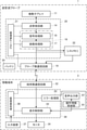
- FIG. 1 is a block diagram showing a configuration of an ultrasonic system according to an embodiment of the present invention.
- the ultrasonic system shown in FIG. 1 includes an ultrasonic probe 1 and a handheld information terminal 3 connected to the ultrasonic probe 1 by wire or wirelessly.
- the ultrasonic system of the present embodiment is realized by an ultrasonic probe 1, a handheld information terminal 3, and an application program for ultrasonic diagnosis operating on the information terminal 3.
- the ultrasonic probe 1 scans a subject with an ultrasonic beam to capture an ultrasonic image, and outputs data corresponding to the ultrasonic image, and in the case of the present embodiment, image information data of the ultrasonic image.
- the ultrasonic probe 1 includes an oscillator array 11, a transmission / reception circuit 14, a signal processing unit 16, an image processing unit 17, a probe-side communication circuit 18, a probe control unit 21, and a cine memory. 22 and a battery 24 are provided.
- a transmission / reception circuit 14 is bidirectionally connected to the oscillator array 11.
- a signal processing unit 16, an image processing unit 17, and a probe-side communication circuit 18 are sequentially connected in series to the transmission / reception circuit 14.
- the signal processing unit 16 and the image processing unit 17 constitute an image information data generation unit 19.
- a cine memory 22 is connected to the image processing unit 17, and a probe-side communication circuit 18 is connected to the cine memory 22.
- the probe control unit 21 is connected to the transmission / reception circuit 14, the signal processing unit 16, the image processing unit 17, the cine memory 22, and the probe-side communication circuit 18. Further, the ultrasonic probe 1 has a built-in battery 24.
- the probe side processor 25 is configured by the transmission / reception circuit 14, the image information data generation unit 19 (signal processing unit 16 and image processing unit 17), and the probe control unit 21.
- the oscillator array 11 has a plurality of ultrasonic oscillators arranged one-dimensionally or two-dimensionally. Each of these oscillators transmits ultrasonic waves according to the drive signal supplied from the transmission / reception circuit 14, receives the reflected wave from the subject, and outputs an analog reception signal.
- Each oscillator includes, for example, a piezoelectric ceramic represented by PZT (Lead Zirconate Titanate), a polymer piezoelectric element represented by PVDF (Poly Vinylidene Di Fluoride), and PMN-PT (Piezoelectric element).
- Lead Magnesium Niobate-Lead Titanate is composed of elements in which electrodes are formed at both ends of a piezoelectric body made of a piezoelectric single crystal or the like represented by lead magnesium niobate-lead titanate.
- the transmission / reception circuit 14 transmits ultrasonic waves from the vibrator array 11 and performs reception focus processing on the reception signal output from the vibrator array 11 that has received the ultrasonic echo. By doing so, a sound line signal is generated.
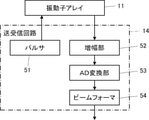
- the transmission / reception circuit 14 includes a pulser 51 connected to the oscillator array 11, an amplification unit 52 sequentially connected in series from the oscillator array 11, an AD (Analog Digital) conversion unit 53, and a beam former. It has 54 and.
- the pulsar 51 includes, for example, a plurality of pulse generators, and ultrasonic waves transmitted from the plurality of oscillators of the oscillator array 11 emit an ultrasonic beam based on a transmission delay pattern selected by the probe control unit 21.
- Each drive signal is supplied to a plurality of oscillators by adjusting the delay amount so as to form.
- a pulsed or continuous wave voltage is applied to the electrodes of the vibrator of the vibrator array 11
- the piezoelectric body expands and contracts, and pulsed or continuous wave ultrasonic waves are generated from each vibrator.
- An ultrasonic beam is formed from the combined waves of those ultrasonic waves.
- the transmitted ultrasonic beam is reflected by, for example, a target such as a site of a subject, and propagates toward the vibrator array 11 of the ultrasonic probe 1.
- Each oscillator constituting the oscillator array 11 expands and contracts by receiving the ultrasonic echo propagating toward the oscillator array 11 in this way to generate a received signal which is an electric signal, and these are received.
- the signal is output to the amplification unit 52.
- the amplification unit 52 amplifies the signal input from each of the oscillators constituting the oscillator array 11, and transmits the amplified signal to the AD conversion unit 53.
- the AD conversion unit 53 converts the signal transmitted from the amplification unit 52 into digital reception data, and outputs these reception data to the beam former 54.
- the beam former 54 adds a delay to each received data converted by the AD conversion unit 53 according to the sound velocity or the distribution of the sound velocity set based on the reception delay pattern selected by the probe control unit 21. By doing so, so-called reception focus processing is performed.
- reception focus processing each received data converted by the AD conversion unit 53 is phase-adjusted and added, and a sound line signal in which the focus of the ultrasonic echo is narrowed down is generated.
- the image information data generation unit 19 generates image information data based on the sound line signal generated by the transmission / reception circuit 14. As described above, the image information data generation unit 19 has a signal processing unit 16 and an image processing unit 17.
- the signal processing unit 16 Under the control of the probe control unit 21, the signal processing unit 16 generates image signal data before imaging into an ultrasonic image based on the sound line signal generated by the transmission / reception circuit 14. More specifically, the signal processing unit 16 processes the sound line signal generated by the beamformer 54 of the transmission / reception circuit 14, for example, attenuation due to the propagation distance according to the depth of the position where the ultrasonic wave is reflected. After the correction of, the envelope detection process is performed to generate a signal representing tomographic image information about the tissue in the subject as the image signal data before imaging.
- the image processing unit 17 Under the control of the probe control unit 21, the image processing unit 17 generates an ultrasonic image as image information data generated by the image information data generation unit 19 based on the image signal data generated by the signal processing unit 16. do. More specifically, the image processing unit 17 raster-converts the image signal data before imaging generated by the signal processing unit 16 into an image signal according to a normal television signal scanning method, and is converted in this way. An ultrasonic image is obtained by performing various image processing such as brightness correction, gradation correction, sharpness correction, image size correction, refresh rate correction, scanning frequency correction, and color correction according to the display format of the monitor 34 on the image signal. After generating (ultrasonic image signal), the generated ultrasonic image is output to the probe side communication circuit 18 as image information data.
- the cine memory 22 stores the image information data generated by the image information data generation unit 19 under the control of the probe control unit 21. More specifically, the cine memory 22 stores the ultrasonic image generated by the image processing unit 17 of the image information data generation unit 19 as the image information data in the live mode.
- the cine memory 22 has a memory capacity for storing an ultrasonic image of several tens to several tens of seconds, for example, an ultrasonic image of 30 frames per second, and an ultrasonic image of several tens to several hundreds of frames. is doing.
- the cine memory 22 is a ring buffer.
- the ultrasonic images of the past frames corresponding to the memory capacity are stored in the cine memory 22
- the ultrasonic images of the latest frame are sequentially stored in the cine memory 22 instead of the ultrasonic images of the oldest frame.
- the cine memory 22 always stores the ultrasonic image of the past frame of the number of frames corresponding to the memory capacity from the ultrasonic image of the latest frame.
- the live mode is a mode in which ultrasonic images (moving images) captured at a constant frame rate are sequentially displayed (real-time display).
- the freeze mode the ultrasonic image (moving image) captured in the live mode is stored in the cine memory 22, and the ultrasonic image (moving image) of the past frame stored in the cine memory 22 is selected.
- This mode reads and displays an ultrasonic image (still image) of an arbitrary frame.
- the probe-side communication circuit 18 transmits the image information data generated by the image processing unit 17 or the image information data stored in the cine memory 22 by wire or wirelessly.
- the probe-side communication circuit 18 includes an antenna for transmitting and receiving radio waves, and modulates a carrier based on an ultrasonic image generated by an image processing unit 17 to transmit a transmission signal.
- An ultrasonic image is transmitted wirelessly by generating and supplying a transmission signal to an antenna and transmitting radio waves from the antenna.
- Carrier modulation methods include ASK (Amplitude Shift Keying), PSK (Phase Shift Keying), QPSK (Quadrature Phase Shift Keying), and 16QAM (16 Quadrature Amplitude). Modulation: 16 quadrature phase shift keying) and the like are used.
- the probe-side communication circuit 18 can also connect the ultrasonic probe 1 and the information terminal 3 by wire with a cable such as a USB (Universal Serial Bus) cable.
- the probe-side communication circuit 18 wirelessly transmits the image information data of the frame generated by the image information data generation unit 19 in the live mode, and wirelessly transmits the image information data stored in the cine memory 22 in the freeze mode. Send.
- the probe control unit 21 controls each part of the ultrasonic probe 1 based on a program or the like stored in advance. More specifically, the probe control unit 21 controls the transmission / reception circuit 14 so that the transmission of the ultrasonic beam and the reception of the ultrasonic echo are performed based on the preset inspection mode and scanning method. Further, the probe control unit 21 has the signal processing unit 16 and the signal processing unit 16 of the image information data generation unit 19 so that preset signal processing is applied to the sound line signal and preset image processing is applied to the image signal data. The image processing unit 17 is controlled. In the probe control unit 21, the image information data generated by the image information data generation unit 19 is stored in the cine memory 22 in the live mode, and the past frame stored in the cine memory 22 is stored in the freeze mode. Control so that the sound wave image is read out. Further, the probe control unit 21 controls the probe-side communication circuit 18 so that the image signal data is transmitted at a preset transmission radio wave intensity.
- the inspection mode includes B (brightness) mode, CF (color Doppler) mode, PD (power Doppler) mode, M (motion) mode, PW (pulse Doppler) mode, CW (continuous wave Doppler) mode, and the like. It indicates any of the inspection modes that can be used in the ultrasonic system, and the scanning method shall indicate one of scanning methods such as an electronic sector scanning method, an electronic linear scanning method, and an electronic convex scanning method.
- the battery 24 is built in the ultrasonic probe 1 and supplies electric power to each circuit of the ultrasonic probe 1.
- the information terminal 3 is a handheld type terminal device such as a smartphone and a tablet PC, and displays an ultrasonic image based on data corresponding to the ultrasonic image captured by the ultrasonic probe 1.
- the information terminal 3 includes a terminal-side communication circuit 32, a display control unit 33, an error processing unit 35, a terminal control unit 36, a monitor (display unit) 34, an input device 37, and the like. It is equipped with.
- the display control unit 33 and the monitor 34 are sequentially connected in series to the terminal-side communication circuit 32. Further, the terminal control unit 36 is connected to the terminal side communication circuit 32, the display control unit 33, and the error processing unit 35. Further, an input device 37 is connected to the terminal control unit 36.
- the probe-side communication circuit 18 of the ultrasonic probe 1 and the terminal-side communication circuit 32 of the information terminal 3 are wirelessly connected by wireless communication, whereby the ultrasonic probe 1 and the information terminal 3 are connected to each other. However, it is connected so that information can be exchanged in both directions.
- the terminal-side communication circuit 32 receives the image information data transmitted from the probe-side communication circuit 18 of the ultrasonic probe 1 by wire or wirelessly under the control of the terminal control unit 36.
- the terminal-side communication circuit 32 includes an antenna for transmitting and receiving radio waves, and receives and receives a transmission signal wirelessly transmitted from the probe-side communication circuit 18 via the antenna. By demodulating the transmitted signal, an ultrasonic image (ultrasonic image signal), which is image information data, is output.
- the display control unit 33 causes the monitor 34 to display various information under the control of the terminal control unit 36.
- the display control unit 33 causes the monitor 34 to display an ultrasonic image based on the image information data received by, for example, the terminal side communication circuit 32. More specifically, the display control unit 33 performs a predetermined process on the ultrasonic image which is the image information data, and displays it on the monitor 34. Further, when an error occurs in the ultrasonic system, the display control unit 33 causes the monitor 34 to display information on the type of the error that has occurred, operation information for resolving the error, and the like.
- the error processing unit 35 Under the control of the terminal control unit 36, the error processing unit 35 displays information on the type of error that has occurred when an error has been detected in the ultrasonic system, and has operational information for resolving the error. Etc. are proposed to the user (operator of the ultrasonic system). As shown in FIG. 4, the error processing unit 35 includes an operation information storage unit 61, an error detection unit 62, an operation information acquisition unit 63, an elapsed time determination unit 64, an operation count determination unit 66, and a voice output unit. 67 and.
- the type of error is not particularly limited, but for example, in addition to a malfunction of the ultrasonic system, an error at the time of wireless connection between the ultrasonic probe 1 and the information terminal 3 or connection with a wired cable, and an ultrasonic image will be captured. Includes errors such as error when inputting patient information of the patient, operation error by the user, and setting error.
- the operation information is various information (advice) proposed to the user in order to solve the error when the error occurs, such as the procedure of the operation performed by the user to solve the error.
- the operation information may be a text message, a video, a voice, or the like, and is not particularly limited.
- the operation information for resolving an error in a wireless connection is an operation of tapping a scan button of an application program for ultrasonic diagnosis. , The operation of tapping the probe addition button, the operation of tapping the probe switching button, and the like.
- the operation information acquisition unit 63 and the operation count determination unit 66 are sequentially connected in series to the error detection unit 62. Further, an elapsed time determination unit 64 is connected to the error detection unit 62, and an operation count determination unit 66 is connected to the elapsed time determination unit 64. A voice output unit 67 is connected to the operation information storage unit 61 and the error detection unit 62. Further, an operation information storage unit 61 is connected to the error detection unit 62, and a display control unit 33 is connected to the operation information storage unit 61 and the operation count determination unit 66.
- the operation information storage unit 61 stores a plurality of operation information corresponding to the operation performed by the user in order to solve the error for each type of error generated in the ultrasonic system.
- the operation information storage unit 61 stores a plurality of operation information corresponding to operations performed by the user, for example, in order to solve a wireless connection error.
- the error detection unit 62 detects whether or not an error has occurred in the ultrasonic system.
- the error detection unit 62 detects whether or not a wireless connection error has occurred, including errors such as an operation error and a setting error.
- the method of detecting the occurrence of an error is not particularly limited, but for example, between the ultrasonic probe 1 and the information terminal 3 for confirming whether the setting of the wireless connection between the ultrasonic probe 1 and the information terminal 3 is correct. Includes detecting whether or not the patient is connected by wire, detecting whether or not the patient information input is correct, and the like. In addition, when the number of operations corresponding to the operation information performed by the user reaches the specified number of times within the specified period after the first operation for resolving the error is performed by the user. In addition, it may be detected that an error has occurred.
- the operation information acquisition unit 63 acquires user operation information, which is information on operations performed by a user who has read the operation information, in order to resolve the error when the error detection unit 62 detects the occurrence of an error. do.
- the user's operation is not particularly limited, but for example, an operation for setting a wireless connection between the ultrasonic probe 1 and the information terminal 3, an operation for connecting the ultrasonic probe 1 and the information terminal 3 with a wired cable, and a correct operation. Includes operations such as re-entering patient information.
- the elapsed time determination unit 64 determines whether or not the elapsed time since the occurrence of the error was detected has elapsed a predetermined period.
- the elapsed time determination unit 64 measures the elapsed time with a timer or the like, and determines whether or not the measured elapsed time has elapsed for a predetermined period, for example, 2 minutes.
- the operation count determination unit 66 is based on the user operation information acquired by the operation information acquisition unit 63 when the elapsed time determination unit 64 determines that the elapsed time has not elapsed a predetermined period. It is determined whether or not the number of operations corresponding to the operation information performed by the user has reached the specified number of times within the specified period.
- the operation count determination unit 66 counts, for example, the number of times the wireless connection of the information terminal 3 is set by the user within a predetermined period after the occurrence of the error is detected by a counter or the like, and the counted value is calculated. It is determined whether or not the specified number of times, for example, two times has been reached.
- the voice output unit 67 reads out various types of information by voice, and includes, for example, a speaker, earphones, headphones, and the like.
- the terminal control unit 36 controls each unit of the information terminal 3 based on a program stored in advance and a user's instruction input from the input device 37. More specifically, the terminal control unit 36 controls the terminal-side communication circuit 32 so that the transmission signal is received from the probe-side communication circuit 18 of the ultrasonic probe 1. Further, the terminal control unit 36 controls the display control unit 33 so that the ultrasonic image is displayed on the monitor 34 based on the image information data. Further, the terminal control unit 36 controls the error processing unit 35 so as to propose to the user operation information for resolving the error when an error occurs.
- the terminal side processor 39 is configured by the display control unit 33, the error detection unit 62 of the error processing unit 35, the operation information acquisition unit 63, the elapsed time determination unit 64, the operation count determination unit 66, and the terminal control unit 36. There is.
- the monitor 34 displays various information.
- the monitor 34 displays, for example, an ultrasonic image generated by the display control unit 33, error type information, operation information, and the like.
- Examples of the monitor 34 include an LCD (Liquid Crystal Display) and an organic EL (Electro-Luminescence) display.
- the input device 37 is for the user to perform an input operation and input various instructions, and in the case of the present embodiment, the input device 37 includes a touch panel or the like on which the user can perform a touch operation to input various instructions. ..
- the ultrasonic wave is transmitted by the transmission / reception circuit 14 in a state where the ultrasonic probe 1 is in contact with the body surface of the subject. Transmission is started and a sound wave signal is generated (step S2).
- an ultrasonic beam is transmitted from the plurality of oscillators of the oscillator array 11 into the subject according to the drive signal from the pulsar 51 of the transmission / reception circuit 14.
- the ultrasonic echo from the subject based on the ultrasonic beam transmitted from the pulsar 51 is received by each oscillator of the oscillator array 11, and is an analog signal from each oscillator of the oscillator array 11 that has received the ultrasonic echo.
- a certain received signal is output.
- the received signal which is an analog signal output from each oscillator of the oscillator array 11, is amplified by the amplification unit 52 of the transmission / reception circuit 14, and AD-converted by the AD conversion unit 53 to acquire the received data.
- a sound line signal is generated by performing reception focus processing on the received data by the beam former 54.
- the image information data generation unit 19 generates an ultrasonic image as image information data based on the sound line signal generated by the beam former 54 of the transmission / reception circuit 14 (step S3).
- the sound line signal generated by the beam former 54 is subjected to various signal processing by the signal processing unit 16 of the image information data generation unit 19, and as image signal data before imaging, a fault relating to the tissue in the subject is obtained.
- a signal representing image information is generated.
- the image signal data generated by the signal processing unit 16 is raster-converted by the image processing unit 17, and further subjected to various image processing to generate an ultrasonic image as image information data.
- the ultrasonic image generated by the image processing unit 17 is stored in the cine memory 22 (step S4).
- the ultrasonic image generated by the image processing unit 17 is wirelessly transmitted from the probe side communication circuit 18 to the information terminal 3 (step S5).
- the ultrasonic image wirelessly transmitted from the probe-side communication circuit 18 of the ultrasonic probe 1 is received by the terminal-side communication circuit 32 under the control of the terminal control unit 36 of the information terminal 3 (step S6). ..
- the display control unit 33 performs a predetermined process on the ultrasonic image received by the terminal side communication circuit 32 and displays it on the monitor 34 (step S7).
- the ultrasonic image generated by the image processing unit 17 of the image information data generation unit 19 of the ultrasonic probe 1 is wirelessly transmitted from the probe side communication circuit 18 as the image information data.
- the display control unit 33 of the information terminal 3 causes the monitor 34 to display the ultrasonic image received by the terminal-side communication circuit 32.
- step S8 When the freeze mode is specified based on the user's instruction input from the input device 37 (step S8), the transmission of ultrasonic waves from the oscillator array 11 is stopped (step S9).
- the ultrasonic image of the past frame stored in the cine memory 22 is read out as the image information data and wirelessly transmitted from the probe side communication circuit 18 (step S10).
- the ultrasonic image wirelessly transmitted from the probe-side communication circuit 18 is received by the terminal-side communication circuit 32 (step S11).
- the display control unit 33 causes the monitor 34 to display the ultrasonic image of the past frame received by the terminal side communication circuit 32 (step S12).
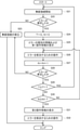
- the user wirelessly connects the ultrasonic probe 1 and the information terminal 3 (step S21).
- the user selects, for example, from a list of a plurality of registered ultrasonic probes by tapping the ultrasonic probe 1 to be used.
- the error detection unit 62 detects whether or not a wireless connection error has occurred between the ultrasonic probe 1 and the information terminal 3 (step S22).
- step S22 if the occurrence of an error is not detected (NO in step S22), a wireless connection between the ultrasonic probe 1 and the information terminal 3 is established (step S23). As a result, the ultrasonic image corresponding to the image information data transmitted from the ultrasonic probe 1 and received by the information terminal 3 is displayed on the monitor 34.
- a plurality of operation information corresponding to the error of the wireless connection is read from the operation information storage unit 61, and at least one operation is performed from the operation information on the higher priority side among the read operation information.
- the first operation information which is information, is selected.
- the display control unit 33 displays the information on the type of the error that has occurred and the first operation information on the monitor 34 (step S25).
- the user reads the information of the error type displayed on the monitor 34, understands that the error of the wireless connection has occurred between the ultrasonic probe 1 and the information terminal 3, and also the first operation information.
- the operation corresponding to this first operation information is performed (step S26).
- the operation information acquisition unit 63 acquires the user operation information.
- the error detection unit 62 detects whether or not a wireless connection error has occurred between the ultrasonic probe 1 and the information terminal 3, that is, whether or not the error has been resolved by the user's operation (the error detection unit 62). Step S28).
- step S28 if the occurrence of an error is not detected (NO in step S28), that is, if the error is resolved by the user's operation, the process proceeds to step S23, and the ultrasonic image is displayed on the monitor 34.
- the elapsed time determination unit 64 subsequently causes an error. It is determined whether or not the elapsed time T from the detection has passed a predetermined period T1, for example, 2 minutes (T ⁇ T1?) (Step S29).
- step S30 when the elapsed time T has passed the predetermined period T1 (YES in step S29), the process returns to step S21 and the process is restarted from the beginning.
- the elapsed time T has elapsed the specified period T1
- the same operation is performed for a short time by the user, for example, one hour after the occurrence of the error is detected, or the same operation is performed the next day. Not repeated during, in other words, the user means to restart the wireless connection from the beginning.
- the operation count determination unit 66 when the elapsed time T does not elapse the predetermined period T1 (NO in step S29), the operation count determination unit 66 subsequently sets the operation count N to the predetermined number N1, for example, twice. Whether or not it has been reached (N ⁇ N1?) Is determined (step S30).
- step S30 if the number of operations N has not reached the predetermined number of times N1 (NO in step S30), the process returns to step S26. Therefore, the user performs the operation corresponding to the first operation information again, for example. That is, the user repeats the same operation.
- the number of operations N reaches the specified number of times N1 (YES in step S30)
- a plurality of operations corresponding to wireless connection errors corresponding to operations not performed by the user by the display control unit 33 a plurality of operations corresponding to wireless connection errors corresponding to operations not performed by the user by the display control unit 33.
- the second operation information which is at least one operation information among the information, is displayed on the monitor 34 (step S31).
- step S32 the user reads the second operation information displayed on the monitor 34 and performs an operation corresponding to the second operation information.
- the display control unit 33 monitors the first operation information among the plurality of operation information corresponding to the wireless connection error. To display.
- the operation information acquisition unit 63 acquires the user operation information of the operation corresponding to the first operation information performed by the user who has read the first operation information, and the elapsed time since the occurrence of the error is detected.
- Whether or not the specified period has elapsed is determined by the elapsed time determination unit 64, and when it is determined that the elapsed time has not passed the specified period, based on the user operation information, The operation count determination unit 66 determines whether or not the number of operations corresponding to the first operation information performed by the user within a predetermined period has reached the predetermined number of operations. Then, after displaying the first operation information, the display control unit 33 proposes the second operation information to the user when the number of operations reaches the predetermined number of times within the specified period.
- the number of operations corresponding to the first operation information performed by the user in order to solve the error of the wireless connection reaches the specified number of times within the specified period.
- the user in order to propose to the user the second operation information corresponding to the operation not performed by the user, the user performs the operation corresponding to the first operation information a specified number of times within a specified period. After that, the operation corresponding to the second operation information can be performed. Therefore, according to the ultrasonic system, it is possible to support the user to solve the error of the wireless communication without repeating the same operation.
- the number of operation information to be displayed at one time can be set according to the screen size of the monitor 34. For example, when the screen size of the monitor 34 is small, one operation information is displayed at a time, and when the screen size is large, three operation information is displayed at a time.
- icons 71 of application programs for ultrasonic diagnosis and icons of various application programs are displayed.
- the main menu screen is displayed as shown in FIG.
- a setting button 72 for making various settings for the application program for ultrasonic diagnosis
- a scan button 73 for scanning the subject with an ultrasonic beam
- an application for ultrasonic diagnosis Various buttons such as an end button 74 for terminating the program are displayed.
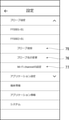
- the setting screen shown in FIG. 9 is displayed. Items such as probe settings, application settings, terminal information, application information and system are displayed on the setting screen.
- the probe setting items include a list of registered ultrasonic probe names, a probe addition button 75 for adding a new ultrasonic probe, a probe name change button 76 for changing the name of an ultrasonic probe, and a probe name change button 76.
- the Wi-Fi channel setting button 77 for setting the Wi-Fi channel, and the like are displayed.
- FF0001-01 and FF0002-01 are the names of registered ultrasonic probes. That is, the user can confirm the name of the registered ultrasonic probe on the setting screen.
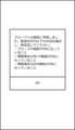
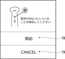
- the error type information a message indicating that the new ultrasonic probe was not detected and this error are resolved. Operation information for is displayed. This allows the user to read the error type information, understand that a new ultrasonic probe was not detected, read the operation information, and perform an operation to resolve this error.
- the cancel button (CANCEL) 79 is tapped on the ultrasonic probe detection start screen, the addition of a new ultrasonic probe is stopped and the screen returns to the setting screen.
- the scan screen shown in FIG. 11 is displayed.
- the subject (patient) is scanned by the ultrasonic beam, and the image information data of the scanned subject is transferred from the ultrasonic probe 1 to the information terminal 3. It is transmitted wirelessly.
- the ultrasonic image corresponding to the image information data received from the ultrasonic probe 1 is displayed on the scan screen.
- the scan menu button 81 is displayed in the upper right corner of the scan screen. When the scan menu button 81 is tapped, the scan menu screen is displayed as shown in FIG.
- the scan menu screen displays an inspection end button 82 for ending the inspection, a menu return button 83 for returning to the menu screen, and a probe switching button 84 for switching the ultrasonic probe to be used.
- a display screen of a list of names of ultrasonic probes that can be wirelessly connected to the information terminal 3 is displayed.
- the name of any one ultrasonic probe is tapped on the display screen of the list, the connection between the ultrasonic probe in use and the information terminal 3 is disconnected, and then the tapped ultrasonic probe and information. It is wirelessly connected to the terminal 3. That is, the user can switch the ultrasonic probe to be used to the tapped ultrasonic probe by tapping the name of any ultrasonic probe displayed in the list.
- a probe addition button 85 is displayed on the list display screen.
- the function of the probe addition button 85 on the list display screen is the same as that of the probe addition button 75 on the setting screen. That is, by tapping the probe addition button 75 on the setting screen or tapping the probe addition button 85 on the list display screen, the detection start screen of the ultrasonic probe shown in FIG. 10 can be displayed. ..
- the examination end button 82 When the examination end button 82 is tapped on the scan menu screen, the examination (scan) is completed, and various items (patient information, saved images, etc.) set for examining this patient are combined into one examination. After being transferred to the inspection history and initializing various items, the screen returns to the scan screen shown in FIG. On the other hand, when the button 83 for returning to the menu is tapped, various items are initialized and the screen returns to the main menu screen shown in FIG.
- the user can perform operations such as confirming the name of the registered ultrasonic probe, scanning the subject, adding a new ultrasonic probe, and switching the ultrasonic probe to be used. can.
- Example 1 When the scan button is tapped by the user, if there is no problem, the ultrasonic probe 1 and the information terminal 3 in the user's hand are wirelessly connected, and the ultrasonic wave is connected in the ultrasonic probe 1. The subject is scanned by the beam, the image information data is transmitted from the ultrasonic probe 1, and the information terminal 3 should display the ultrasonic image corresponding to the image information data received from the ultrasonic probe 1.
- the user can (1) tap the scan button again, (2) tap the probe switching button to reselect the ultrasonic probe 1 to be used, and (3). ) It is assumed that the operation of adding the ultrasonic probe 1 to be used is performed in a short time by tapping the probe addition button, but the ultrasonic image is not displayed.
- the error processing unit 35 will select "ultrasonic probe and information" when, for example, the operations (1) to (3) are performed a total of three times within 2 minutes after the operation (1) is performed. Please display the operation information "Please try a wired connection with the terminal" in a message.
- the total of three operations is not limited to the case where the operation (1), the operation (2), and the operation (3) are performed once, for example, only the operation (1) is performed three times. When repeated, the case where the operation (1) and the operation (2) are performed three times in total is included. That is, the number of operations may be the total number of times a single operation is performed, or may be the total number of times two or more operations are performed.
- the error processing unit 35 when the number of operations of the operation corresponding to the first operation information, which is at least one operation information, performed by the user, the error processing unit 35 reaches the specified number of times within the specified period.
- the second operation information which is at least one operation information corresponding to the operation not performed by the user among the plurality of operation information, the operation of connecting the ultrasonic probe 1 and the information terminal 3 with a wired cable. Can be suggested.
- the ultrasonic image can be displayed regardless of the wireless connection error. May be displayed.
- Example 2 Similarly, when the user taps the scan button, the ultrasound image is not displayed and the error type information and operation information are displayed as shown on the left side of FIG. Therefore, in order to try to reconnect the ultrasonic probe 1 to be used wirelessly, the user (4) displays a list of registered ultrasonic probes, as shown on the right side of FIG. 14, and As an operation to reconnect the ultrasonic probe 1 wirelessly, tap the (5) Add probe button without scrolling the name of the ultrasonic probe displayed in the list, and select the ultrasonic probe 1 you want to use. It is assumed that the addition operation is repeated in a short period of time, but the ultrasonic image is not displayed.
- the error processing unit 35 "scrolls not yet" when the operations (4) and (5) are performed three or more times in total within two minutes after the operation (4) is performed. Display the displayed ultrasonic probe and select it. "
- the error processing unit 35 displays a list including only the names of a predetermined number of ultrasonic probes among the group of ultrasonic probes that can be wirelessly connected to the information terminal 3, and the number of operations is determined. Propose an operation to select an undisplayed ultrasonic probe that is not displayed in the list from the group of ultrasonic probes as the second operation information when the specified number of times is reached within the specified period. Can be done.
- the name of the ultrasonic probe displayed in the list can be scrolled even if the user does not know that it can be scrolled and unused. Since the name of the ultrasonic probe can be displayed, the undisplayed ultrasonic probe can be tried without repeating the operation of adding the ultrasonic probe to be used.
- Example 3 In the case of the second embodiment, when the number of operations reaches the specified number of times within the specified period, the error processing unit 35 uses information instead of reading the operation information by voice as the second operation information.
- An operation of selecting an ultrasonic probe by a wizard method from a group of ultrasonic probes that can be wirelessly connected to the terminal 3 may be proposed.
- the error processing unit 35 is described as "convex type or linear" when the operations (4) and (5) are performed three or more times in total within two minutes after the operation (4) is performed.
- the operation information "Which type of ultrasonic probe is better?" Is displayed in a message.
- the error handling unit 35 displays a list containing only the names of the linear ultrasonic probes. Then, the user selects the name of the ultrasonic probe to be used from the names of the linear ultrasonic probes displayed in the list.
- the user can use the ultrasonic probe displayed in the list. You can efficiently select the ultrasonic probe you want to use without scrolling the name to display undisplayed ultrasonic probes that are not displayed in the list.
- Example 4 Similarly, when the user tapped the scan button, the ultrasound image was not displayed. Therefore, in order to attempt to reconnect the ultrasonic probe 1 to be used wirelessly, the user (6) an operation of displaying a list of registered ultrasonic probes, is displayed in the list, as shown in FIG. (7) Tap and select an ultrasonic probe from the list of ultrasonic probes displayed in the list without scrolling the name of the ultrasonic probe, and (8) Add probe button. It is assumed that the operation of adding the ultrasonic probe 1 by tapping is repeated in a short period of time, but the ultrasonic image is not displayed.
- the error processing unit 35 will "untried ultrasonic waves" when the operations (6) to (8) are performed a total of three times within 2 minutes after the operation (6) is performed. Please select a probe. "
- the error processing unit 35 provides the second operation information of the ultrasonic probe capable of wirelessly connecting to the information terminal 3. It is possible to propose an operation of selecting an untried ultrasonic probe for which wireless connection with the information terminal 3 has not been tried after the operation corresponding to the first operation information is performed by the user in the group.
- the untried ultrasound By proposing an operation to select an untried ultrasound probe, the untried ultrasound even if the user does not know that the name of the ultrasound probe displayed in the list can be scrolled. Since it is possible to understand that there is a probe and find an untried ultrasonic probe, it is possible to try an untried ultrasonic probe without repeating the operation of selecting and adding the ultrasonic probe 1. ..
- the name of the untried ultrasonic probe is included in a list including only the names of a predetermined number of ultrasonic probes.
- This list may be displayed side by side from the beginning. In this case, the name of the untried ultrasonic probe may be further highlighted.
- the list may be displayed by including only the names of untried ultrasonic probes in a list containing only the names of a predetermined number of ultrasonic probes. This makes it easier for the user to identify the untried ultrasonic probe.
- the error processing unit 35 may display the second operation information as a text message or a moving image by the display control unit 33, or may have the voice output unit 67 read the second operation information by voice. good. By having the second operation information read aloud, the content of the second operation information can be proposed to the user regardless of the size of the display screen of the information terminal 3.
- the image processing unit 17 may be provided on the information terminal 3 side instead of the ultrasonic probe 1 side.
- the signal processing unit 16 generates image signal data before imaging into an ultrasonic image, and the image signal data generated by the signal processing unit 16 is transmitted from the probe-side communication circuit 18 of the ultrasonic probe 1 to an information terminal. It is wirelessly transmitted to the terminal-side communication circuit 32 of No. 3, and an ultrasonic image is generated based on the image signal data in the image processing unit of the information terminal 3.
- the gain and the like are adjusted according to the display characteristics of the monitor 34.
- the hardware-like configuration of the processing unit (Processing Unit) that executes various processes such as the unit 66) and the terminal control unit 36 may be dedicated hardware, or various processors or computers that execute programs. May be.
- the hardware configuration of the cine memory 22 and the operation information storage unit 61 may be dedicated hardware, or a memory such as a semiconductor memory, an HDD (Hard Disk Drive), and an SSD (Solid). It may be a storage device such as State Drive).
- the circuit configuration can be changed after manufacturing the CPU (Central Processing Unit), FPGA (Field Programmable Gate Array), etc., which are general-purpose processors that execute software (programs) and function as various processing units.
- Programmable Logic Device (PLD), ASIC (Application Specific Integrated Circuit), etc. which is a processor, includes a dedicated electric circuit, which is a processor having a circuit configuration designed exclusively for performing specific processing. ..
- One processing unit may be composed of one of these various processors, or a combination of two or more processors of the same type or different types, for example, a combination of a plurality of FPGAs, or a combination of an FPGA and a CPU. It may be configured by such as. Further, a plurality of processing units may be configured by one of various processors, or two or more of the plurality of processing units may be collectively configured by using one processor.
- processors are configured by a combination of one or more CPUs and software, and this processor functions as a plurality of processing units.
- SoC system on chip
- a processor that realizes the functions of the entire system including a plurality of processing units with one IC (Integrated Circuit) chip is used.
- circuitry that combines circuit elements such as semiconductor elements.
- the method of the present invention can be carried out, for example, by a program for causing a computer to execute each step. It is also possible to provide a computer-readable recording medium on which this program is recorded.
- Application program icon 72 setting button, 73 scan button, 74 end button, 75 probe add button, 76 probe name change button, 77 Wi-Fi channel setting button, 78 start button, 79 cancel button, 81 scan menu Button, 82 inspection end button, 83 menu return button, 84 probe switching button, 85 probe addition button.
Landscapes
- Engineering & Computer Science (AREA)
- Health & Medical Sciences (AREA)
- Life Sciences & Earth Sciences (AREA)
- Physics & Mathematics (AREA)
- Theoretical Computer Science (AREA)
- Medical Informatics (AREA)
- General Health & Medical Sciences (AREA)
- Pathology (AREA)
- Biomedical Technology (AREA)
- Heart & Thoracic Surgery (AREA)
- Nuclear Medicine, Radiotherapy & Molecular Imaging (AREA)
- Molecular Biology (AREA)
- Surgery (AREA)
- Animal Behavior & Ethology (AREA)
- Radiology & Medical Imaging (AREA)
- Public Health (AREA)
- Veterinary Medicine (AREA)
- Biophysics (AREA)
- Quality & Reliability (AREA)
- General Engineering & Computer Science (AREA)
- General Physics & Mathematics (AREA)
- Computer Networks & Wireless Communication (AREA)
- Ultra Sonic Daignosis Equipment (AREA)
Abstract
超音波システムおよび超音波システムの制御方法においては、ユーザによって行われる、無線接続のエラーに対応する複数の操作情報のうちの少なくとも1つの操作情報である第1操作情報に対応する操作の操作回数が、定められた期間内に、定められた回数に到達した場合に、ユーザによって行われていない操作に対応する、複数の操作情報のうちの少なくとも1つの操作情報である第2操作情報をユーザに提案する。
Description
本発明は、超音波プローブと、ハンドヘルド型の情報端末と、が有線または無線で接続される超音波システムおよび超音波システムの制御方法に関する。
従来から、医療分野において、超音波画像を利用する超音波システムが実用化されている。一般に、超音波システムは、振動子アレイを内蔵する超音波プローブと、超音波プローブと接続される情報端末と、を備えており、超音波プローブから被検体に向けて超音波ビームを送信し、被検体からの超音波エコーを超音波プローブで受信し、その受信信号を電気的に処理することにより超音波画像が生成される。
近年では、据置型の超音波システムのみならず、携帯型およびハンドヘルド型の超音波システムが開発されている。携帯型の超音波システムは、情報端末が、ラップトップ型の端末装置によって実現されている超音波専用システムである。一方、ハンドヘルド型の超音波システムは、情報端末が、スマートフォンまたはタブレットPC(Personal Computer:パーソナルコンピュータ)等のハンドヘルド型の端末装置と、端末装置上で動作する超音波診断用のアプリケーションプログラムと、によって実現されている。
ここで、本発明の参考となる先行技術文献として、特許文献1-5がある。
特許文献1は、情報提供装置等に関するものである。特許文献1には、ユーザによる繰り返し操作を検出し、検出された繰り返し操作の操作履歴を解析し、内部記憶手段および外部記憶手段等の記憶手段に、操作履歴に対応して記憶された操作情報から、記憶手段に記憶された操作履歴を参照して、解析された繰り返し操作の操作履歴に対応する操作情報を特定し、特定された操作情報を出力することが記載されている。
特許文献2は、誤操作防止装置等に関するものである。特許文献2には、操作者が行った操作画面上の操作を記憶し、記憶した操作の中で操作画面上に誤り表示がなされた操作およびその操作回数を計数し、計数した計数値が予め設定された所定の値を越えると、計数値が所定の値を越えた特定の操作を操作画面上で操作できないように制御したり、特定の操作が誤りであることを操作画面上で報知したりすることが記載されている。
特許文献3は、医用装置の誤操作防止装置に関するものである。特許文献3には、表示装置の画面に表示される操作ボタンをタッチまたはクリックする操作により、所望の処理を実行させるようにしたソフトキーを有する医用装置において、操作ボタンを所定時間操作し続けるか、所定時間内に所定回数操作を繰り返すことにより、所望の処理の実行を開始させることが記載されている。
特許文献4は、可搬型の超音波撮像システム等に関するものである。特許文献4には、超音波探触子と、超音波探触子から情報を受信するように構成された可搬型のホストシステムとを含む超音波撮像システムにおいて、ホストシステムが、ホストシステムにより特定された超音波探触子を表示し、操作者が、対応するアイコンに触れることにより、表示された探触子の1つを選択することが記載されている。
特許文献5は、超音波撮像装置および多用途電子表示装置を含む超音波撮像システムに関するものである。特許文献5には、事前記憶情報、ユーザ入力、および超音波撮像装置から集められる情報等に基づいて、1つ以上の超音波撮像装置から、多用途電子表示装置と接続する超音波撮像装置を選択し、選択された超音波撮像装置から受信される超音波データを表示する超音波撮像システムが記載されている。
ハンドヘルド型の超音波システムは、据置型および携帯型の超音波システムに比べて表示画面が小さいため、メッセージを表示させることにより、ユーザに一度に報知することができる情報量が限られている。
他方、超音波システムは、検査部位等に応じて複数の超音波プローブを使い分ける必要がある。従来の据置型の超音波システムの多くは、情報端末に2~3個の超音波プローブを有線ケーブルで接続可能である。ユーザは、これらの2~3個の超音波プローブの中から、使用したい超音波プローブを機械的な選択スイッチで選択するか、あるいは、情報端末の表示画面のUI(User Interface:ユーザインタフェイス)によって選択して使用する。
一方、ハンドヘルド型の超音波システムの場合、超音波プローブと情報端末との間は、例えば無線で接続される。無線接続の場合、ユーザが接続したい超音波プローブと実際に接続されている超音波プローブとが一致しているか否かは、有線接続の場合のように物理的な接続で目視することはできず、情報端末の小さな表示画面において、無線接続の情報を見て確認するしかない。
また、超音波プローブと情報端末との間を2~3mの有線ケーブルで接続する場合と異なり、無線接続する場合、無線の電波が届く範囲であれば、検査室外の、例えば10m以上離れた場所にある超音波プローブにも無線接続される可能性がある。このため、ユーザは、手元にある超音波プローブに接続したいにも係わらず、手元の超音波プローブとは接続されず、検査室外の遠く離れた場所にある超音波プローブと接続される場合がある。
病院には、無線接続が可能な多くの超音波プローブが多くの場所にある。このため、看護師が手元にある超音波プローブを無線で接続しようと試みてもうまく接続されず、何度も同じ操作を繰り返してもうまく接続されない場合がある。例えば、ユーザが手元にある超音波プローブに無線で接続するための操作を試みるが、実際には、遠く離れた場所にある超音波プローブに接続されており、情報端末の表示画面に超音波画像が表示されないため、ユーザは、接続操作を繰り返す。
また、無線接続のための操作として、登録済みの超音波プローブの名称のリストを表示させ、その中から、ユーザが使用したい超音波プローブを選択して接続する操作、および、新規な超音波プローブを追加する操作等がある。
ところが、情報端末の表示画面が小さいため、登録済みの超音波プローブの数が多く、一度に全ての超音波プローブの名称を表示させることができない場合には、定められた個数の超音波プローブの名称のみを含むリストを表示させる。ユーザは、リストに表示されている超音波プローブの名称をスクロールさせることによって、リストに表示されていない未表示の超音波プローブの名称を表示させることができる。
この場合、リストに表示されている超音波プローブの名称をスクロールさせなければ、未表示の超音波プローブの名称を表示させることはできないが、ユーザが、このような操作上の制約を知らない場合、新規な超音波プローブを追加するための操作を繰り返す。
例えば、5個以上の超音波プローブが登録済みであるが、図13に示すように、一度に4個の超音波プローブの名称のみを含むリストが表示されるとする。ユーザは、表示されている超音波プローブの名称を上下方向にスワイプすることにより未表示の超音波プローブの名称を表示させることができる。スクロールさせると、超音波プローブの名称の右端にスクロールバーが表示されるが、このスクロールバーは、仕様上、超音波プローブの名称を上下方向にスクロールさせた場合に、数秒間、表示されるだけである。
しかし、ユーザが、このような仕様上の制約を把握しているとは限らない。ユーザが、リストに表示されている超音波プローブの名称をスクロールさせることができることを知らない場合、複数の超音波プローブを切り替えて使おうとしても、使用したい超音波プローブの名称が表示されていないため、使用したい超音波プローブが登録されていないと勘違いをして、新規な超音波プローブを追加する操作を繰り返す。
あるいは、超音波プローブの電源がオンになっていることを確認し、超音波ビームにより被検体をスキャンするためのスキャンボタンをタップするか、使用する超音波プローブを切り替えるためのプローブ切り替えボタンをタップしても超音波画像が表示されない。さらに、登録済みの超音波プローブの中から、使用したい超音波プローブを一旦削除し、再度、追加した後、スキャンボタンをタップしても超音波画像が表示されない。そのため、ユーザは、無線接続を諦めて、有線ケーブルで接続する。
このように、無線接続のエラーが発生して、超音波画像が表示されない場合、ユーザは、無線接続のエラーを解決するために、上記のような思いつく限りの操作を行う。しかし、上記の仕様上の制約の問題は、無線接続のエラーではあるが、実質的なエラーではなく、ユーザによる操作ミスであるため、この問題を解決するためのメッセージ等は表示されない。このため、ユーザは、使用したい超音波プローブの名称が表示されない理由が分からず、エラーを解決できない状態が続く。
従って、本発明は、上記従来の問題点を解消し、ユーザが、同じ操作を繰り返すことなく、無線接続のエラーを解決できるようにサポートすることができる超音波システムおよび超音波システムの制御方法を提供することを目的とする。
上記目的を達成するために、本発明は、超音波プローブと、超音波プローブと有線または無線で接続されるハンドヘルド型の情報端末と、を備える超音波システムであって、
情報端末は、
超音波プローブと情報端末との間の無線接続のエラーを解決するために、ユーザによって行われる操作に対応する複数の操作情報を格納する操作情報格納部と、
ユーザによって行われる、複数の操作情報のうちの少なくとも1つの操作情報である第1操作情報に対応する操作の操作回数が、定められた期間内に、定められた回数に到達した場合に、ユーザによって行われていない操作に対応する、複数の操作情報のうちの少なくとも1つの操作情報である第2操作情報をユーザに提案するエラー処理部と、を備える、超音波システムを提供する。
情報端末は、
超音波プローブと情報端末との間の無線接続のエラーを解決するために、ユーザによって行われる操作に対応する複数の操作情報を格納する操作情報格納部と、
ユーザによって行われる、複数の操作情報のうちの少なくとも1つの操作情報である第1操作情報に対応する操作の操作回数が、定められた期間内に、定められた回数に到達した場合に、ユーザによって行われていない操作に対応する、複数の操作情報のうちの少なくとも1つの操作情報である第2操作情報をユーザに提案するエラー処理部と、を備える、超音波システムを提供する。
ここで、エラー処理部は、操作回数が、定められた期間内に、定められた回数に到達した場合に、第2操作情報として、超音波プローブと情報端末との間を有線ケーブルで接続する操作を提案することが好ましい。
また、エラー処理部は、情報端末と無線接続が可能な超音波プローブの群のうち、定められた個数の超音波プローブの名称のみを含むリストを表示させ、操作回数が、定められた期間内に、定められた回数に到達した場合に、第2操作情報として、超音波プローブの群のうち、リストに含まれていない未表示の超音波プローブを選択する操作を提案することが好ましい。
また、エラー処理部は、操作回数が、定められた期間内に、定められた回数に到達した場合に、第2操作情報として、情報端末と無線接続が可能な超音波プローブの群の中から、ウィザード方式で超音波プローブを選択する操作を提案することが好ましい。
また、エラー処理部は、操作回数が、定められた期間内に、定められた回数に到達した場合に、第2操作情報として、情報端末と無線接続が可能な超音波プローブの群のうち、ユーザによって第1操作情報に対応する操作が行われてから、情報端末との無線接続が試されていない未試行の超音波プローブを選択する操作を提案することが好ましい。
また、エラー処理部は、未試行の超音波プローブの名称が先頭側から並べられ、かつ、定められた個数の超音波プローブの名称のみを含むリストを表示させることが好ましい。
また、エラー処理部は、未試行の超音波プローブの名称をハイライトさせることが好ましい。
また、エラー処理部は、未試行の超音波プローブの名称のみが並べられ、かつ、定められた個数の超音波プローブの名称のみを含むリストを表示させることが好ましい。
また、エラー処理部は、第2操作情報をテキストメッセージまたは動画で表示させることが好ましい。
また、エラー処理部は、第2操作情報を音声で読み上げさせることが好ましい。
また、本発明は、超音波プローブと、超音波プローブと有線または無線で接続されるハンドヘルド型の情報端末と、を備える超音波システムの制御方法であって、
超音波プローブと情報端末との間の無線接続のエラーを解決するために、ユーザによって行われる操作に対応する複数の操作情報を、情報端末の操作情報格納部が格納するステップと、
ユーザによって行われる、複数の操作情報のうちの少なくとも1つの操作情報である第1操作情報に対応する操作の操作回数が、定められた期間内に、定められた回数に到達した場合に、ユーザによって行われていない操作に対応する、複数の操作情報のうちの少なくとも1つの操作情報である第2操作情報を、情報端末のエラー処理部がユーザに提案するステップと、を含む、超音波システムの制御方法を提供する。
超音波プローブと情報端末との間の無線接続のエラーを解決するために、ユーザによって行われる操作に対応する複数の操作情報を、情報端末の操作情報格納部が格納するステップと、
ユーザによって行われる、複数の操作情報のうちの少なくとも1つの操作情報である第1操作情報に対応する操作の操作回数が、定められた期間内に、定められた回数に到達した場合に、ユーザによって行われていない操作に対応する、複数の操作情報のうちの少なくとも1つの操作情報である第2操作情報を、情報端末のエラー処理部がユーザに提案するステップと、を含む、超音波システムの制御方法を提供する。
本発明では、無線接続のエラーを解決するために、ユーザによって行われる、第1操作情報に対応する操作の操作回数が、定められた期間内に、定められた回数に到達した場合に、ユーザによって行われていない操作に対応する第2操作情報をユーザに提案するため、ユーザは、定められた期間内に、定められた回数、第1操作情報に対応する操作を行った後に、第2操作情報に対応する操作を行うことができる。そのため、本発明によれば、ユーザが、同じ操作を繰り返すことなく、無線接続のエラーを解決できるようにサポートすることができる。
以下に、添付の図面に示す好適実施形態に基づいて、本発明の超音波システムおよび超音波システムの制御方法を詳細に説明する。
図1は、本発明に係る一実施形態の超音波システムの構成を表すブロック図である。図1に示す超音波システムは、超音波プローブ1と、超音波プローブ1と有線または無線で接続されるハンドヘルド型の情報端末3と、を備えている。本実施形態の超音波システムは、超音波プローブ1と、ハンドヘルド型の情報端末3と、情報端末3上で動作する超音波診断用のアプリケーションプログラムと、によって実現されている。
超音波プローブ1は、超音波ビームにより被検体をスキャンして超音波画像を撮像し、超音波画像に対応するデータ、本実施形態の場合、超音波画像の画像情報データを出力する。超音波プローブ1は、図1に示すように、振動子アレイ11と、送受信回路14と、信号処理部16と、画像処理部17と、プローブ側通信回路18と、プローブ制御部21と、シネメモリ22と、バッテリ24と、を備えている。
振動子アレイ11には、送受信回路14が双方向に接続されている。送受信回路14には、信号処理部16、画像処理部17およびプローブ側通信回路18が順次直列に接続されている。信号処理部16および画像処理部17は、画像情報データ生成部19を構成する。また、画像処理部17にはシネメモリ22が接続され、シネメモリ22にはプローブ側通信回路18が接続されている。
また、送受信回路14、信号処理部16、画像処理部17、シネメモリ22およびプローブ側通信回路18には、プローブ制御部21が接続されている。また、超音波プローブ1は、バッテリ24を内蔵している。
送受信回路14、画像情報データ生成部19(信号処理部16および画像処理部17)およびプローブ制御部21により、プローブ側プロセッサ25が構成されている。
送受信回路14、画像情報データ生成部19(信号処理部16および画像処理部17)およびプローブ制御部21により、プローブ側プロセッサ25が構成されている。
振動子アレイ11は、1次元または2次元に配列された複数の超音波振動子を有している。これらの振動子は、それぞれ送受信回路14から供給される駆動信号に従って超音波を送信し、かつ、被検体からの反射波を受信してアナログの受信信号を出力する。
各振動子は、例えば、PZT(Lead Zirconate Titanate:チタン酸ジルコン酸鉛)に代表される圧電セラミック、PVDF(Poly Vinylidene Di Fluoride:ポリフッ化ビニリデン)に代表される高分子圧電素子およびPMN-PT(Lead Magnesium Niobate-Lead Titanate:マグネシウムニオブ酸鉛-チタン酸鉛固溶体)に代表される圧電単結晶等からなる圧電体の両端に電極を形成した素子を用いて構成される。
各振動子は、例えば、PZT(Lead Zirconate Titanate:チタン酸ジルコン酸鉛)に代表される圧電セラミック、PVDF(Poly Vinylidene Di Fluoride:ポリフッ化ビニリデン)に代表される高分子圧電素子およびPMN-PT(Lead Magnesium Niobate-Lead Titanate:マグネシウムニオブ酸鉛-チタン酸鉛固溶体)に代表される圧電単結晶等からなる圧電体の両端に電極を形成した素子を用いて構成される。
送受信回路14は、プローブ制御部21による制御の下で、振動子アレイ11から超音波を送信させ、かつ、超音波エコーを受信した振動子アレイ11から出力される受信信号に受信フォーカス処理を施すことにより音線信号を生成する。送受信回路14は、図2に示すように、振動子アレイ11に接続されるパルサ51と、振動子アレイ11から順次直列に接続される増幅部52、AD(Analog Digital)変換部53およびビームフォーマ54と、を有している。
パルサ51は、例えば複数のパルス発生器を含んでおり、プローブ制御部21により選択された送信遅延パターンに基づいて、振動子アレイ11の複数の振動子から送信される超音波が超音波ビームを形成するようにそれぞれの駆動信号を、遅延量を調節して複数の振動子に供給する。このように、振動子アレイ11の振動子の電極にパルス状または連続波状の電圧が印加されると、圧電体が伸縮し、それぞれの振動子からパルス状または連続波状の超音波が発生して、それらの超音波の合成波から、超音波ビームが形成される。
送信された超音波ビームは、例えば、被検体の部位等の対象において反射され、超音波プローブ1の振動子アレイ11に向かって伝搬する。振動子アレイ11を構成するそれぞれの振動子は、このように振動子アレイ11に向かって伝搬する超音波エコーを受信することにより伸縮して、電気信号である受信信号を発生し、これらの受信信号を増幅部52に出力する。
増幅部52は、振動子アレイ11を構成するそれぞれの振動子から入力された信号を増幅し、増幅した信号をAD変換部53に送信する。AD変換部53は、増幅部52から送信された信号をデジタルの受信データに変換し、これらの受信データをビームフォーマ54に出力する。
ビームフォーマ54は、プローブ制御部21により選択された受信遅延パターンに基づいて設定される音速または音速の分布に従い、AD変換部53により変換された各受信データに対してそれぞれの遅延を与えて加算することにより、いわゆる受信フォーカス処理を行う。この受信フォーカス処理により、AD変換部53で変換された各受信データが整相加算され、かつ、超音波エコーの焦点が絞り込まれた音線信号が生成される。
画像情報データ生成部19は、送受信回路14により生成された音線信号に基づいて画像情報データを生成する。画像情報データ生成部19は、前述のように、信号処理部16と、画像処理部17と、を有している。
信号処理部16は、プローブ制御部21の制御の下で、送受信回路14により生成された音線信号に基づいて、超音波画像への画像化前の画像信号データを生成する。より具体的には、信号処理部16は、送受信回路14のビームフォーマ54により生成された音線信号に対して信号処理、例えば超音波が反射した位置の深度に応じて伝搬距離に起因する減衰の補正を施した後、包絡線検波処理を施して、画像化前の画像信号データとして、被検体内の組織に関する断層画像情報を表す信号を生成する。
画像処理部17は、プローブ制御部21の制御の下で、信号処理部16により生成された画像信号データに基づいて、画像情報データ生成部19により生成された画像情報データとして超音波画像を生成する。より具体的には、画像処理部17は、信号処理部16により生成された画像化前の画像信号データを、通常のテレビジョン信号の走査方式に従う画像信号にラスター変換し、このように変換された画像信号に対して、モニタ34の表示フォーマットに従う明るさ補正、諧調補正、シャープネス補正、画像サイズ補正、リフレッシュレート補正、走査周波数補正および色補正等の各種の画像処理を施すことにより超音波画像(超音波画像信号)を生成した後、生成された超音波画像を画像情報データとしてプローブ側通信回路18に出力する。
シネメモリ22は、プローブ制御部21による制御の下で、画像情報データ生成部19により生成された画像情報データを格納する。より詳しくは、シネメモリ22は、ライブモードの場合に、画像情報データとして、画像情報データ生成部19の画像処理部17により生成された超音波画像を格納する。シネメモリ22は、数秒から数十秒の超音波画像、例えば1秒間に30フレームの超音波画像が撮像される場合、数十フレームから数百フレームの超音波画像を格納するためのメモリ容量を有している。
シネメモリ22はリングバッファである。従って、メモリ容量に対応するフレーム数の過去のフレームの超音波画像がシネメモリ22に格納されると、最古のフレームの超音波画像の代わりに、最新のフレームの超音波画像がシネメモリ22に順次格納される。これにより、シネメモリ22には、常に、最新のフレームの超音波画像から、メモリ容量に対応するフレーム数の過去のフレームの超音波画像が格納される。
シネメモリ22はリングバッファである。従って、メモリ容量に対応するフレーム数の過去のフレームの超音波画像がシネメモリ22に格納されると、最古のフレームの超音波画像の代わりに、最新のフレームの超音波画像がシネメモリ22に順次格納される。これにより、シネメモリ22には、常に、最新のフレームの超音波画像から、メモリ容量に対応するフレーム数の過去のフレームの超音波画像が格納される。
ここで、ライブモードは、一定のフレームレートで撮像された超音波画像(動画像)を逐次表示(リアルタイム表示)するモードである。
フリーズモードは、ライブモードの場合に撮像された超音波画像(動画像)をシネメモリ22に格納しておき、このシネメモリ22に格納されている過去のフレームの超音波画像(動画像)の中から任意のフレームの超音波画像(静止画像)を読み出して表示するモードである。
フリーズモードは、ライブモードの場合に撮像された超音波画像(動画像)をシネメモリ22に格納しておき、このシネメモリ22に格納されている過去のフレームの超音波画像(動画像)の中から任意のフレームの超音波画像(静止画像)を読み出して表示するモードである。
プローブ側通信回路18は、プローブ制御部21の制御の下で、画像処理部17により生成された画像情報データ、または、シネメモリ22に格納された画像情報データを有線または無線で送信する。
プローブ側通信回路18は、本実施形態の場合、電波の送信および受信を行うためのアンテナを含んでおり、画像処理部17により生成された超音波画像に基づいてキャリアを変調して伝送信号を生成し、伝送信号をアンテナに供給してアンテナから電波を送信することにより、超音波画像を無線送信する。
キャリアの変調方式としては、ASK(Amplitude Shift Keying:振幅偏移変調)、PSK(Phase Shift Keying:位相偏移変調)、QPSK(Quadrature Phase Shift Keying:四位相偏移変調)、16QAM(16 Quadrature Amplitude Modulation:16直角位相振幅変調)等が用いられる。
また、プローブ側通信回路18は、超音波プローブ1と情報端末3とを、USB(Universal Serial Bus:ユニバーサル・シリアル・バス)ケーブル等のケーブルによって有線で接続することもできる。
プローブ側通信回路18は、本実施形態の場合、電波の送信および受信を行うためのアンテナを含んでおり、画像処理部17により生成された超音波画像に基づいてキャリアを変調して伝送信号を生成し、伝送信号をアンテナに供給してアンテナから電波を送信することにより、超音波画像を無線送信する。
キャリアの変調方式としては、ASK(Amplitude Shift Keying:振幅偏移変調)、PSK(Phase Shift Keying:位相偏移変調)、QPSK(Quadrature Phase Shift Keying:四位相偏移変調)、16QAM(16 Quadrature Amplitude Modulation:16直角位相振幅変調)等が用いられる。
また、プローブ側通信回路18は、超音波プローブ1と情報端末3とを、USB(Universal Serial Bus:ユニバーサル・シリアル・バス)ケーブル等のケーブルによって有線で接続することもできる。
プローブ側通信回路18は、ライブモードの場合に、画像情報データ生成部19により生成されたフレームの画像情報データを無線送信し、フリーズモードの場合に、シネメモリ22に格納される画像情報データを無線送信する。
プローブ制御部21は、予め記憶しているプログラム等に基づいて、超音波プローブ1の各部の制御を行う。より詳しくは、プローブ制御部21は、予め設定された検査モードおよび走査方式に基づいて、超音波ビームの送信および超音波エコーの受信が行われるように送受信回路14を制御する。また、プローブ制御部21は、予め設定された信号処理が音線信号に施され、予め設定された画像処理が画像信号データに施されるように画像情報データ生成部19の信号処理部16および画像処理部17を制御する。プローブ制御部21は、ライブモードの場合に、画像情報データ生成部19により生成された画像情報データがシネメモリ22に格納され、フリーズモードの場合に、シネメモリ22に格納されている過去のフレームの超音波画像が読み出されるように制御する。さらに、プローブ制御部21は、予め設定された送信電波強度で画像信号データの送信が行われるようにプローブ側通信回路18を制御する。
ここで、検査モードとは、B(輝度)モード、CF(カラードプラ)モード、PD(パワードプラ)モード、M(モーション)モード、PW(パルスドプラ)モード、CW(連続波ドプラ)モード等、超音波システムにおいて使用可能な検査モードのうちのいずれかを示し、走査方式は、電子セクタ走査方式、電子リニア走査方式、電子コンベックス走査方式等の走査方式のうちのいずれかを示すものとする。
バッテリ24は、超音波プローブ1に内蔵されており、超音波プローブ1の各回路に電力を供給する。
次に、情報端末3は、スマートフォンおよびタブレットPC等のようなハンドヘルド型の端末装置であって、超音波プローブ1によって撮像された超音波画像に対応するデータに基づいて超音波画像を表示する。情報端末3は、図1に示すように、端末側通信回路32と、表示制御部33と、エラー処理部35と、端末制御部36と、モニタ(表示部)34と、入力装置37と、を備えている。
端末側通信回路32には、表示制御部33およびモニタ34が順次直列に接続されている。また、端末側通信回路32、表示制御部33およびエラー処理部35に端末制御部36が接続されている。また、端末制御部36には、入力装置37が接続されている。
超音波プローブ1のプローブ側通信回路18と情報端末3の端末側通信回路32とは、本実施形態の場合、無線通信により無線接続されており、これにより、超音波プローブ1と情報端末3とが、双方向に情報の受け渡しが可能に接続されている。
端末側通信回路32は、端末制御部36の制御の下で、超音波プローブ1のプローブ側通信回路18から送信される画像情報データを有線または無線で受信する。本実施形態の場合、端末側通信回路32は、電波の送信および受信を行うためのアンテナを含んでおり、プローブ側通信回路18から無線送信された伝送信号を、アンテナを介して受信し、受信した伝送信号を復調することにより、画像情報データである超音波画像(超音波画像信号)を出力する。
表示制御部33は、端末制御部36の制御の下で、各種の情報をモニタ34に表示させる。表示制御部33は、例えば端末側通信回路32により受信された画像情報データに基づいて超音波画像をモニタ34に表示させる。より詳しくは、表示制御部33は、画像情報データである超音波画像に所定の処理を施して、モニタ34に表示させる。また、表示制御部33は、超音波システムにエラーが発生した場合に、発生したエラーの種別の情報およびこのエラーを解決するための操作情報等をモニタ34に表示させる。
エラー処理部35は、端末制御部36の制御の下で、超音波システムにおいて、エラーの発生が検出された場合に、発生したエラーの種別の情報を表示させ、エラーを解決するための操作情報等をユーザ(超音波システムの操作者)に提案する。エラー処理部35は、図4に示すように、操作情報格納部61と、エラー検出部62と、操作情報取得部63と、経過時間判定部64と、操作回数判定部66と、音声出力部67と、を備えている。
エラーの種別は、特に限定されないが、例えば超音波システムの不具合の他、超音波プローブ1と情報端末3との間の無線接続時あるいは有線ケーブルでの接続時のエラー、超音波画像を撮像しようとする患者の患者情報の入力時のエラー、等のユーザによる操作ミスおよび設定ミス等のエラーを含む。
操作情報とは、エラーが発生した場合に、発生したエラーを解決するために、ユーザに提案される各種の情報(アドバイス)であって、エラーを解決するためにユーザが行う操作の手順等の情報を含む。操作情報は、テキストメッセージ、動画および音声等であってもよく、特に限定されないが、例えば無線接続のエラーを解決するための操作情報は、超音波診断用のアプリケーションプログラムのスキャンボタンをタップする操作、プローブ追加ボタンをタップする操作、およびプローブ切り替えボタンをタップする操作、等の情報を含む。
エラー検出部62には、操作情報取得部63および操作回数判定部66が順次直列に接続されている。また、エラー検出部62には、経過時間判定部64が接続され、経過時間判定部64には、操作回数判定部66が接続されている。操作情報格納部61およびエラー検出部62には、音声出力部67が接続されている。また、エラー検出部62には、操作情報格納部61が接続され、操作情報格納部61および操作回数判定部66には、表示制御部33が接続されている。
操作情報格納部61は、超音波システムにおいて発生するエラーの種別毎に、エラーを解決するために、ユーザによって行われる操作に対応する複数の操作情報を格納する。操作情報格納部61は、例えば無線接続のエラーを解決するために、ユーザによって行われる操作に対応する複数の操作情報を格納する。
エラー検出部62は、超音波システムにエラーが発生したか否かを検出する。エラー検出部62は、例えば操作ミスおよび設定ミス等のエラーを含む、無線接続のエラーが発生したか否かを検出する。
エラーの発生の検出方法は、特に限定されないが、例えば超音波プローブ1と情報端末3との間の無線接続の設定が正しいか否かを確認する、超音波プローブ1と情報端末3との間が有線で接続されているか否かを検出する、患者情報の入力が正しいか否かを検出する、等を含む。また、ユーザによってエラーを解決するための最初の操作が行われてから、定められた期間内に、ユーザによって行われる、操作情報に対応する操作の操作回数が、定められた回数に到達した場合に、エラーが発生したと検出してもよい。
操作情報取得部63は、エラー検出部62によってエラーの発生が検出された場合に、発生したエラーを解決するために、操作情報を読んだユーザによって行われる操作の情報であるユーザ操作情報を取得する。
ユーザの操作は、特に限定されないが、例えば超音波プローブ1と情報端末3の間の無線接続の設定を行う操作、超音波プローブ1と情報端末3との間を有線ケーブルで接続する操作、正しい患者情報を入力し直す操作、等を含む。
経過時間判定部64は、エラーの発生が検出されてからの経過時間が、定められた期間を経過したか否かを判定する。
経過時間判定部64は、経過時間をタイマー等によって計測し、計測された経過時間が、定められた期間、例えば2分間を経過したか否かを判定する。
操作回数判定部66は、経過時間判定部64によって、経過時間が、定められた期間を経過していないと判定された場合に、操作情報取得部63によって取得されたユーザ操作情報に基づいて、定められた期間内に、ユーザによって行われる、操作情報に対応する操作の操作回数が、定められた回数に到達したか否かを判定する。
操作回数判定部66は、エラーの発生が検出されてから、定められた期間内に、例えばユーザによって情報端末3の無線接続の設定が行われる回数をカウンタ等により計数し、その計数値が、定められた回数、例えば2回に到達したか否かを判定する。
音声出力部67は、各種の情報を音声で読み上げるものであり、例えばスピーカ、イヤフォンおよびヘッドフォン等を含む。
端末制御部36は、予め記憶されているプログラムおよび入力装置37から入力されたユーザの指示等に基づいて、情報端末3の各部の制御を行う。より詳しくは、端末制御部36は、超音波プローブ1のプローブ側通信回路18から伝送信号の受信が行われるように端末側通信回路32を制御する。また、端末制御部36は、画像情報データに基づいて超音波画像がモニタ34に表示されるように表示制御部33を制御する。さらに、端末制御部36は、エラーが発生した場合に、発生したエラーを解決するための操作情報をユーザに提案するようにエラー処理部35を制御する。
表示制御部33と、エラー処理部35のエラー検出部62、操作情報取得部63、経過時間判定部64および操作回数判定部66と、端末制御部36と、によって端末側プロセッサ39が構成されている。
モニタ34は、各種の情報を表示する。モニタ34は、例えば表示制御部33により生成された超音波画像、エラーの種別の情報および操作情報等を表示する。
モニタ34としては、例えばLCD(Liquid Crystal Display:液晶ディスプレイ)および有機EL(Electro-Luminescence:エレクトロルミネッセンス)ディスプレイ等を例示することができる。
モニタ34としては、例えばLCD(Liquid Crystal Display:液晶ディスプレイ)および有機EL(Electro-Luminescence:エレクトロルミネッセンス)ディスプレイ等を例示することができる。
入力装置37は、ユーザが入力操作を行って各種の指示を入力するためのものであり、本実施形態の場合、ユーザがタッチ操作を行って各種の指示を入力することができるタッチパネル等を含む。
次に、図4のフローチャートを参照しながら、超音波システムの動作について説明する。まず、ライブモードの場合の超音波システムの動作を説明する。
入力装置37から入力されたユーザからの指示に基づいてライブモードが指定されると(ステップS1)、超音波プローブ1が被検体の体表面上に接触された状態において、送受信回路14により超音波の送信が開始され、音線信号が生成される(ステップS2)。
つまり、プローブ制御部21の制御の下で、送受信回路14のパルサ51からの駆動信号に従って振動子アレイ11の複数の振動子から被検体内に超音波ビームが送信される。
パルサ51から送信された超音波ビームに基づく被検体からの超音波エコーは、振動子アレイ11の各振動子により受信され、超音波エコーを受信した振動子アレイ11の各振動子からアナログ信号である受信信号が出力される。
振動子アレイ11の各振動子から出力されるアナログ信号である受信信号は、送受信回路14の増幅部52により増幅され、AD変換部53によりAD変換されて受信データが取得される。
この受信データに対して、ビームフォーマ54により受信フォーカス処理が施されることにより、音線信号が生成される。
パルサ51から送信された超音波ビームに基づく被検体からの超音波エコーは、振動子アレイ11の各振動子により受信され、超音波エコーを受信した振動子アレイ11の各振動子からアナログ信号である受信信号が出力される。
振動子アレイ11の各振動子から出力されるアナログ信号である受信信号は、送受信回路14の増幅部52により増幅され、AD変換部53によりAD変換されて受信データが取得される。
この受信データに対して、ビームフォーマ54により受信フォーカス処理が施されることにより、音線信号が生成される。
続いて、画像情報データ生成部19により、送受信回路14のビームフォーマ54により生成された音線信号に基づいて、画像情報データとして超音波画像が生成される(ステップS3)。
つまり、ビームフォーマ54により生成された音線信号は、画像情報データ生成部19の信号処理部16により各種の信号処理が施され、画像化前の画像信号データとして、被検体内の組織に関する断層画像情報を表す信号が生成される。
信号処理部16により生成された画像信号データは、画像処理部17によりラスター変換され、さらに各種の画像処理が施され、画像情報データとして超音波画像が生成される。
信号処理部16により生成された画像信号データは、画像処理部17によりラスター変換され、さらに各種の画像処理が施され、画像情報データとして超音波画像が生成される。
画像処理部17により生成された超音波画像は、シネメモリ22に格納される(ステップS4)。
また、画像処理部17により生成された超音波画像は、プローブ側通信回路18から情報端末3に向けて無線送信される(ステップS5)。
続いて、超音波プローブ1のプローブ側通信回路18から無線送信された超音波画像は、情報端末3の端末制御部36の制御の下で、端末側通信回路32により受信される(ステップS6)。
続いて、表示制御部33は、端末側通信回路32により受信された超音波画像に所定の処理を施して、モニタ34に表示させる(ステップS7)。
つまり、ライブモードの場合、画像情報データとして、超音波プローブ1の画像情報データ生成部19の画像処理部17により生成された超音波画像がプローブ側通信回路18から無線送信される。一方、情報端末3の表示制御部33は、端末側通信回路32により受信された超音波画像をモニタ34に表示させる。
次に、フリーズモードの場合の超音波システムの動作を説明する。
入力装置37から入力されたユーザの指示に基づいてフリーズモードが指定されると(ステップS8)、振動子アレイ11からの超音波の送信が停止される(ステップS9)。
この場合、画像情報データとして、シネメモリ22に格納されている過去のフレームの超音波画像が読み出されてプローブ側通信回路18から無線送信される(ステップS10)。
続いて、端末側通信回路32によりプローブ側通信回路18から無線送信された超音波画像が受信される(ステップS11)。
続いて、表示制御部33は、端末側通信回路32により受信された過去のフレームの超音波画像をモニタ34に表示させる(ステップS12)。
次に、図5のフローチャートを参照しながら、超音波プローブ1と情報端末3との間を無線で接続する場合の超音波システムの動作を説明する。
まず、ユーザは、超音波プローブ1と情報端末3との間を無線で接続する(ステップS21)。この場合、ユーザは、例えば登録済みの複数の超音波プローブのリストの中から、使用したい超音波プローブ1をタップすることによって選択する。
使用したい超音波プローブ1が選択されると、エラー検出部62により、超音波プローブ1と情報端末3との間に無線接続のエラーが発生したか否かが検出される(ステップS22)。
その結果、エラーの発生が検出されなかった場合(ステップS22でNO)、超音波プローブ1と情報端末3との間の無線接続が確立される(ステップS23)。これにより、超音波プローブ1から送信され、情報端末3で受信された画像情報データに対応する超音波画像がモニタ34に表示される。
一方、エラーの発生が検出された場合(ステップS22でYES)、経過時間判定部64により、経過時間Tが、T=0に設定(初期化)され、かつ、操作回数判定部66により、操作回数Nが、N=0に設定(初期化)される(ステップS24)。
続いて、操作情報格納部61から、無線接続のエラーに対応する複数の操作情報が読み出され、読み出された複数の操作情報のうち、優先度が高い側の操作情報から少なくとも1つの操作情報である第1操作情報が選択される。そして、表示制御部33により、図6に示すように、発生したエラーの種別の情報および第1操作情報がモニタ34に表示される(ステップS25)。
一方、エラーの発生が検出された場合(ステップS22でYES)、経過時間判定部64により、経過時間Tが、T=0に設定(初期化)され、かつ、操作回数判定部66により、操作回数Nが、N=0に設定(初期化)される(ステップS24)。
続いて、操作情報格納部61から、無線接続のエラーに対応する複数の操作情報が読み出され、読み出された複数の操作情報のうち、優先度が高い側の操作情報から少なくとも1つの操作情報である第1操作情報が選択される。そして、表示制御部33により、図6に示すように、発生したエラーの種別の情報および第1操作情報がモニタ34に表示される(ステップS25)。
続いて、ユーザは、モニタ34に表示されたエラーの種別の情報を読んで、超音波プローブ1と情報端末3との間に無線接続のエラーが発生したことを理解し、同じく第1操作情報を読んで、エラーを解決するために、この第1操作情報に対応する操作を行う(ステップS26)。ユーザによって第1操作情報に対応する操作が行われると、操作情報取得部63により、ユーザ操作情報が取得される。
続いて、ユーザ操作情報に基づいて、ユーザによって第1操作情報に対応する操作が行われたことが分かると、操作回数判定部66により、操作回数Nが、N=N+1に設定される(ステップS27)。
続いて、エラー検出部62により、超音波プローブ1と情報端末3との間に無線接続のエラーが発生したか否か、つまり、ユーザの操作によってエラーが解決されたか否かが検出される(ステップS28)。
その結果、エラーの発生が検出されなかった場合(ステップS28でNO)、つまり、ユーザの操作によってエラーが解決された場合、ステップS23に進み、超音波画像がモニタ34に表示される。
一方、エラーが発生していることが検出された場合(ステップS28でYES)、つまり、ユーザの操作によってもエラーが解決されていない場合、続いて、経過時間判定部64により、エラーの発生が検出されてからの経過時間Tが、定められた期間T1、例えば2分間を経過したか否か(T≧T1?)が判定される(ステップS29)。
一方、エラーが発生していることが検出された場合(ステップS28でYES)、つまり、ユーザの操作によってもエラーが解決されていない場合、続いて、経過時間判定部64により、エラーの発生が検出されてからの経過時間Tが、定められた期間T1、例えば2分間を経過したか否か(T≧T1?)が判定される(ステップS29)。
その結果、経過時間Tが、定められた期間T1を経過した場合(ステップS29でYES)、ステップS21に戻り、最初からやり直す。経過時間Tが、定められた期間T1を経過した場合、エラーの発生が検出されてから、例えば1時間後に、あるいは、翌日に、同じ操作が行われるというように、ユーザによって同じ操作が短時間の間に繰り返し行われていない、言い換えると、ユーザは、無線接続を最初からやり直すことを意味する。
一方、経過時間Tが、定められた期間T1を経過していない場合(ステップS29でNO)、続いて、操作回数判定部66により、操作回数Nが、定められた回数N1、例えば2回に到達したか否か(N≧N1?)が判定される(ステップS30)。
一方、経過時間Tが、定められた期間T1を経過していない場合(ステップS29でNO)、続いて、操作回数判定部66により、操作回数Nが、定められた回数N1、例えば2回に到達したか否か(N≧N1?)が判定される(ステップS30)。
その結果、操作回数Nが、定められた回数N1に到達していない場合(ステップS30でNO)、ステップS26に戻る。従って、ユーザは、例えば第1操作情報に対応する操作を再度行う。つまり、ユーザは、同じ操作を繰り返す。
一方、操作回数Nが、定められた回数N1に到達した場合(ステップS30でYES)、表示制御部33により、ユーザによって行われていない操作に対応する、無線接続のエラーに対応する複数の操作情報のうちの少なくとも1つの操作情報である第2操作情報がモニタ34に表示される(ステップS31)。
一方、操作回数Nが、定められた回数N1に到達した場合(ステップS30でYES)、表示制御部33により、ユーザによって行われていない操作に対応する、無線接続のエラーに対応する複数の操作情報のうちの少なくとも1つの操作情報である第2操作情報がモニタ34に表示される(ステップS31)。
続いて、ユーザは、モニタ34に表示された第2操作情報を読んで、この第2操作情報に対応する操作を行う(ステップS32)。
上記のように、超音波システムでは、無線接続のエラーの発生が検出された場合に、無線接続のエラーに対応する複数の操作情報のうち、第1操作情報を、表示制御部33がモニタ34に表示させる。
以下順に、第1操作情報を読んだユーザによって行われる、第1操作情報に対応する操作のユーザ操作情報を、操作情報取得部63が取得し、エラーの発生が検出されてからの経過時間が、定められた期間を経過したか否かを、経過時間判定部64が判定し、この経過時間が、定められた期間を経過していないと判定された場合に、ユーザ操作情報に基づいて、定められた期間内に、ユーザによって行われる、第1操作情報に対応する操作の操作回数が、定められた回数に到達したか否かを、操作回数判定部66が判定する。
そして、表示制御部33が、第1操作情報を表示させた後、操作回数が、定められた期間内に、定められた回数に到達した場合に、第2操作情報をユーザに提案する。
以下順に、第1操作情報を読んだユーザによって行われる、第1操作情報に対応する操作のユーザ操作情報を、操作情報取得部63が取得し、エラーの発生が検出されてからの経過時間が、定められた期間を経過したか否かを、経過時間判定部64が判定し、この経過時間が、定められた期間を経過していないと判定された場合に、ユーザ操作情報に基づいて、定められた期間内に、ユーザによって行われる、第1操作情報に対応する操作の操作回数が、定められた回数に到達したか否かを、操作回数判定部66が判定する。
そして、表示制御部33が、第1操作情報を表示させた後、操作回数が、定められた期間内に、定められた回数に到達した場合に、第2操作情報をユーザに提案する。
このように、超音波システムでは、無線接続のエラーを解決するために、ユーザによって行われる、第1操作情報に対応する操作の操作回数が、定められた期間内に、定められた回数に到達した場合に、ユーザによって行われていない操作に対応する第2操作情報をユーザに提案するため、ユーザは、定められた期間内に、定められた回数、第1操作情報に対応する操作を行った後に、第2操作情報に対応する操作を行うことができる。そのため、超音波システムによれば、ユーザが、同じ操作を繰り返すことなく、無線通信のエラーを解決できるようにサポートすることができる。
なお、一度に表示させる操作情報の個数は、モニタ34の画面サイズに応じて設定することができる。例えば、モニタ34の画面サイズが小さい場合には、一度に1つの操作情報を表示させ、画面サイズが大きい場合には、一度に3つの操作情報を表示させる。
次に、超音波診断用のアプリケーションプログラムの動作を説明する。
図7に示すように、情報端末3のホーム画面には、超音波診断用のアプリケーションプログラムのアイコン71の他、各種のアプリケーションプログラムのアイコンが表示されている。
ユーザによって、超音波診断用のアプリケーションプログラムのアイコン71がタップされると、図8に示すように、メインメニュー画面が表示される。メインメニュー画面には、超音波診断用のアプリケーションプログラムに対して各種の設定を行うための設定ボタン72、超音波ビームによる被検体のスキャンを行うためのスキャンボタン73、および超音波診断用のアプリケーションプログラムを終了させるための終了ボタン74、等の各種のボタンが表示されている。
メインメニュー画面において、設定ボタン72がタップされると、図9に示す設定画面が表示される。設定画面には、プローブ設定、アプリケーション設定、端末情報、アプリケーション情報およびシステム、等の項目が表示されている。
プローブ設定の項目には、登録済みの超音波プローブの名称のリスト、新規な超音波プローブを追加するためのプローブ追加ボタン75、超音波プローブの名称を変更するためのプローブ名の変更ボタン76、およびWi-Fiのチャネルの設定を行うためのWi-Fi channelの設定ボタン77、等が表示されている。図示例の場合、FF0001-01およびFF0002-01が、登録済みの超音波プローブの名称である。
つまり、ユーザは、設定画面において、登録済みの超音波プローブの名称を確認することができる、
つまり、ユーザは、設定画面において、登録済みの超音波プローブの名称を確認することができる、
設定画面において、プローブ追加ボタン75がタップされると、図10に示すように、情報端末3に無線接続が可能な超音波プローブの検出を開始するか、キャンセルするかを選択するための検出開始画面が表示される。
超音波プローブの検出開始画面において、開始ボタン78がタップされると、情報端末3に無線接続が可能な超音波プローブが自動的に検出される。その結果、新規な超音波プローブが検出された場合、検出された新規な超音波プローブの名称が、登録済みの超音波プローブの名称のリストに追加される。
このようにして、ユーザは、新規な超音波プローブを追加することができる。
一方、新規な超音波プローブが検出されなかった場合、前述の図6に示すように、エラーの種別の情報として、新規な超音波プローブが検出されなかったことを表すメッセージおよびこのエラーを解決するための操作情報が表示される。
これにより、ユーザは、エラーの種別の情報を読んで、新規な超音波プローブが検出されなかったことを理解し、操作情報を読んで、このエラーを解決するための操作を行うことができる。
超音波プローブの検出開始画面において、キャンセルボタン(CANCEL)79がタップされると、新規な超音波プローブの追加が中止され、設定画面に戻る。
超音波プローブの検出開始画面において、開始ボタン78がタップされると、情報端末3に無線接続が可能な超音波プローブが自動的に検出される。その結果、新規な超音波プローブが検出された場合、検出された新規な超音波プローブの名称が、登録済みの超音波プローブの名称のリストに追加される。
このようにして、ユーザは、新規な超音波プローブを追加することができる。
一方、新規な超音波プローブが検出されなかった場合、前述の図6に示すように、エラーの種別の情報として、新規な超音波プローブが検出されなかったことを表すメッセージおよびこのエラーを解決するための操作情報が表示される。
これにより、ユーザは、エラーの種別の情報を読んで、新規な超音波プローブが検出されなかったことを理解し、操作情報を読んで、このエラーを解決するための操作を行うことができる。
超音波プローブの検出開始画面において、キャンセルボタン(CANCEL)79がタップされると、新規な超音波プローブの追加が中止され、設定画面に戻る。
メインメニュー画面において、スキャンボタン73がタップされると、図11に示すスキャン画面が表示される。
スキャン画面において、患者情報が入力されて、スキャンが開始されると、超音波ビームにより被検体(患者)がスキャンされ、スキャンされた被検体の画像情報データが超音波プローブ1から情報端末3に無線送信される。そして、情報端末3において、超音波プローブ1から受信された画像情報データに対応する超音波画像がスキャン画面に表示される。
スキャン画面において、患者情報が入力されて、スキャンが開始されると、超音波ビームにより被検体(患者)がスキャンされ、スキャンされた被検体の画像情報データが超音波プローブ1から情報端末3に無線送信される。そして、情報端末3において、超音波プローブ1から受信された画像情報データに対応する超音波画像がスキャン画面に表示される。
スキャン画面の右上には、スキャンのメニューボタン81が表示されている。スキャンのメニューボタン81がタップされると、図12に示すように、スキャンのメニュー画面が表示される。スキャンのメニュー画面には、検査を終了するための検査終了ボタン82、メニュー画面に戻るためのメニューへ戻るボタン83、および使用する超音波プローブを切り替えるためのプローブ切り替えボタン84が表示されている。
スキャンのメニュー画面において、プローブ切り替えボタン84がタップされると、図13に示すように、情報端末3に無線接続が可能な超音波プローブの名称のリストの表示画面が表示される。リストの表示画面において、任意の1つの超音波プローブの名称がタップされると、使用中の超音波プローブと情報端末3との間の接続が切断され、その後、タップされた超音波プローブと情報端末3との間が無線で接続される。
つまり、ユーザは、リストに表示されている任意の超音波プローブの名称をタップすることにより、使用する超音波プローブを、タップした超音波プローブに切り替えることができる。
つまり、ユーザは、リストに表示されている任意の超音波プローブの名称をタップすることにより、使用する超音波プローブを、タップした超音波プローブに切り替えることができる。
リストの表示画面には、情報端末3に無線接続が可能な超音波プローブの名称のリストの他、プローブ追加ボタン85が表示されている。リストの表示画面におけるプローブ追加ボタン85の機能は、設定画面におけるプローブ追加ボタン75と同じである。つまり、設定画面のプローブ追加ボタン75がタップされるか、あるいは、リストの表示画面のプローブ追加ボタン85がタップされることによって、図10に示す超音波プローブの検出開始画面を表示させることができる。
スキャンのメニュー画面において、検査終了ボタン82がタップされると、検査(スキャン)が終了し、この患者を検査するために設定した各種項目(患者情報および保存画像等)が1つの検査にまとめられて検査履歴に移され、各種項目が初期状態にされた後、図11に示すスキャン画面に戻る。一方、メニューへ戻るボタン83がタップされると、各種項目が初期状態にされ、図8に示すメインメニュー画面に戻る。
以上のようにして、ユーザは、登録済みの超音波プローブの名称の確認、被検体のスキャン、新規な超音波プローブの追加、および、使用したい超音波プローブの切り替え、等の操作を行うことができる。
次に、エラーを解決するために、ユーザによって行われる操作について具体例を挙げて説明する。
(実施例1)
ユーザによってスキャンボタンがタップされた場合、何も問題が発生していなければ、ユーザの手元にある超音波プローブ1と情報端末3との間が無線で接続され、超音波プローブ1において、超音波ビームにより被検体がスキャンされ、超音波プローブ1から画像情報データが送信され、情報端末3において、超音波プローブ1から受信された画像情報データに対応する超音波画像が表示されるはずである。
ユーザによってスキャンボタンがタップされた場合、何も問題が発生していなければ、ユーザの手元にある超音波プローブ1と情報端末3との間が無線で接続され、超音波プローブ1において、超音波ビームにより被検体がスキャンされ、超音波プローブ1から画像情報データが送信され、情報端末3において、超音波プローブ1から受信された画像情報データに対応する超音波画像が表示されるはずである。
しかし、ユーザが、スキャンボタンをタップしても、情報端末3の表示画面に超音波画像が表示されなかった。
そのため、ユーザは、この問題を解決するために、(1)スキャンボタンをもう一度タップする操作、(2)プローブ切り替えボタンをタップして、使用したい超音波プローブ1を選び直す操作、および、(3)プローブ追加ボタンをタップして、使用したい超音波プローブ1を追加する操作を短時間の間に行ったが、超音波画像は表示されなかったとする。
そのため、ユーザは、この問題を解決するために、(1)スキャンボタンをもう一度タップする操作、(2)プローブ切り替えボタンをタップして、使用したい超音波プローブ1を選び直す操作、および、(3)プローブ追加ボタンをタップして、使用したい超音波プローブ1を追加する操作を短時間の間に行ったが、超音波画像は表示されなかったとする。
この場合、エラー処理部35は、例えば(1)の操作が行われてから2分以内に、(1)~(3)の操作が合計3回行われた場合に、「超音波プローブと情報端末との間の有線接続を試みてください」という操作情報をメッセージで表示させる。
なお、合計3回の操作とは、(1)の操作、(2)の操作、および、(3)の操作が1回ずつ行われる場合だけでなく、例えば(1)の操作だけが3回繰り返された場合、(1)の操作および(2)の操作が合計で3回行われる場合等を含む。つまり、操作回数とは、単一の操作が行われる合計の回数であってもよいし、あるいは、2以上の操作が行われる合計の回数であってもよい。
このように、エラー処理部35は、ユーザによって行われる、少なくとも1つの操作情報である第1操作情報に対応する操作の操作回数が、定められた期間内に、定められた回数に到達した場合に、複数の操作情報のうち、ユーザによって行われていない操作に対応する少なくとも1つの操作情報である第2操作情報として、超音波プローブ1と情報端末3との間を有線ケーブルで接続する操作を提案することができる。
たとえ無線接続のエラーが発生している場合であっても、使用したい超音波プローブ1と情報端末3との間を有線ケーブルで接続することにより、無線接続のエラーに関わらず、超音波画像が表示される可能性がある。
(実施例2)
同様に、ユーザが、スキャンボタンをタップしても、超音波画像が表示されず、図14の左側に示すように、エラーの種別の情報および操作情報が表示された。
そのため、ユーザは、使用したい超音波プローブ1を無線で接続し直そうと試みるために、図14の右側に示すように、(4)登録済みの超音波プローブのリストを表示させる操作、および、超音波プローブ1を無線で接続し直すための操作として、リストに表示されている超音波プローブの名称をスクロールさせることなく、(5)プローブ追加ボタンをタップして、使用したい超音波プローブ1を追加する操作を短時間の間に繰り返し行ったが、超音波画像は表示されなかったとする。
同様に、ユーザが、スキャンボタンをタップしても、超音波画像が表示されず、図14の左側に示すように、エラーの種別の情報および操作情報が表示された。
そのため、ユーザは、使用したい超音波プローブ1を無線で接続し直そうと試みるために、図14の右側に示すように、(4)登録済みの超音波プローブのリストを表示させる操作、および、超音波プローブ1を無線で接続し直すための操作として、リストに表示されている超音波プローブの名称をスクロールさせることなく、(5)プローブ追加ボタンをタップして、使用したい超音波プローブ1を追加する操作を短時間の間に繰り返し行ったが、超音波画像は表示されなかったとする。
この場合、エラー処理部35は、例えば(4)の操作が行われてから2分以内に、(4)および(5)の操作が合計3回以上行われた場合に、「スクロールして未表示の超音波プローブを表示させて選択してください」という操作情報を音声で読み上げさせる。
このように、エラー処理部35は、情報端末3と無線接続が可能な超音波プローブの群のうち、定められた個数の超音波プローブの名称のみを含むリストを表示させ、操作回数が、定められた期間内に、定められた回数に到達した場合に、第2操作情報として、超音波プローブの群のうち、リストに表示されていない未表示の超音波プローブを選択する操作を提案することができる。
未表示の超音波プローブを選択する操作を提案することにより、ユーザが、リストに表示されている超音波プローブの名称をスクロールさせることができることを知らない場合であっても、スクロールさせて未使用の超音波プローブの名称を表示させることができるため、使用したい超音波プローブを追加する操作を繰り返し行うことなく、未表示の超音波プローブを試すことができる。
(実施例3)
実施例2の場合、エラー処理部35は、操作回数が、定められた期間内に、定められた回数に到達した場合に、第2操作情報として、操作情報を音声で読み上げさせる代わりに、情報端末3と無線接続が可能な超音波プローブの群の中から、ウィザード方式で超音波プローブを選択する操作を提案してもよい。
実施例2の場合、エラー処理部35は、操作回数が、定められた期間内に、定められた回数に到達した場合に、第2操作情報として、操作情報を音声で読み上げさせる代わりに、情報端末3と無線接続が可能な超音波プローブの群の中から、ウィザード方式で超音波プローブを選択する操作を提案してもよい。
この場合、エラー処理部35は、例えば(4)の操作が行われてから2分以内に、(4)および(5)の操作が合計3回以上行われた場合に、「コンベックス型またはリニア型の超音波プローブのどちらがいいですか?」という操作情報をメッセージで表示させる。これに対し、ユーザが、リニア型の超音波プローブを選択したとする。これに応じて、エラー処理部35は、リニア型の超音波プローブの名称のみを含むリストを表示させる。そして、ユーザが、リストに表示されているリニア型の超音波プローブの名称の中から、使用したい超音波プローブの名称を選択する。
このように、ウィザード方式によって、質問および選択項目を表示させ、ユーザによる選択および入力を促すことを繰り返して、処理を対話的に進めることにより、ユーザは、リストに表示されている超音波プローブの名称をスクロールさせて、リストに表示されていない未表示の超音波プローブを表示させることなく、使用したい超音波プローブを効率よく選択することができる。
(実施例4)
同様に、ユーザが、スキャンボタンをタップしても、超音波画像が表示されなかった。
そのため、ユーザは、使用したい超音波プローブ1を無線で接続し直そうと試みるために、図13に示すように、(6)登録済みの超音波プローブのリストを表示させる操作、リストに表示されている超音波プローブの名称をスクロールさせることなく、(7)リストに表示されている超音波プローブのリストの中から、超音波プローブをタップして選択する操作、および、(8)プローブ追加ボタンをタップして超音波プローブ1を追加する操作を短時間の間に繰り返し行ったが、超音波画像は表示されなかったとする。
同様に、ユーザが、スキャンボタンをタップしても、超音波画像が表示されなかった。
そのため、ユーザは、使用したい超音波プローブ1を無線で接続し直そうと試みるために、図13に示すように、(6)登録済みの超音波プローブのリストを表示させる操作、リストに表示されている超音波プローブの名称をスクロールさせることなく、(7)リストに表示されている超音波プローブのリストの中から、超音波プローブをタップして選択する操作、および、(8)プローブ追加ボタンをタップして超音波プローブ1を追加する操作を短時間の間に繰り返し行ったが、超音波画像は表示されなかったとする。
この場合、エラー処理部35は、例えば(6)の操作が行われてから2分以内に、(6)~(8)の操作が合計3回行われた場合に、「未試行の超音波プローブを選択してください」というアドバイスを表示させる。
このように、エラー処理部35は、操作回数が、定められた期間内に、定められた回数に到達した場合に、第2操作情報として、情報端末3と無線接続が可能な超音波プローブの群のうち、ユーザによって第1操作情報に対応する操作が行われてから、情報端末3との無線接続が試されていない未試行の超音波プローブを選択する操作を提案することができる。
未試行の超音波プローブを選択する操作を提案することにより、ユーザが、リストに表示されている超音波プローブの名称をスクロールさせることができることを知らない場合であっても、未試行の超音波プローブがあることを理解し、未試行の超音波プローブを見つけることができるため、超音波プローブ1を選択する操作および追加する操作を繰り返し行うことなく、未試行の超音波プローブを試すことができる。
また、エラー処理部35は、未試行の超音波プローブを選択する操作を提案する場合に、例えば未試行の超音波プローブの名称を、定められた個数の超音波プローブの名称のみを含むリストの先頭側から並べて、このリストを表示させてもよい。この場合、さらに、未試行の超音波プローブの名称をハイライトさせてもよい。あるいは、未試行の超音波プローブの名称のみを、定められた個数の超音波プローブの名称のみを含むリストに含めて、このリストを表示させてもよい。
これにより、ユーザは、未試行の超音波プローブを識別しやすくなる。
これにより、ユーザは、未試行の超音波プローブを識別しやすくなる。
なお、エラー処理部35は、表示制御部33によって、第2操作情報をテキストメッセージまたは動画で表示させてもよいし、あるいは、音声出力部67によって、第2操作情報を音声で読み上げさせてもよい。第2操作情報を音声で読み上げさせることにより、情報端末3の表示画面のサイズに関わらず、第2操作情報の内容をユーザに提案することができる。
画像処理部17は、超音波プローブ1側ではなく、情報端末3側に設けられていてもよい。この場合、信号処理部16によって超音波画像への画像化前の画像信号データが生成され、信号処理部16によって生成された画像信号データが、超音波プローブ1のプローブ側通信回路18から情報端末3の端末側通信回路32に向けて無線送信され、情報端末3の画像処理部において、画像信号データに基づいて超音波画像が生成される。
この場合、情報端末3において、画像信号データに画像処理を行って超音波画像を生成するため、超音波画像をモニタ34に表示させた後で、モニタ34の表示特性に合わせて、ゲイン等の画像処理条件を自由に変更することができるという利点がある。
本発明の装置において、送受信回路14、信号処理部16、画像処理部17、プローブ制御部21、表示制御部33、エラー検出部62、操作情報取得部63、経過時間判定部64、操作回数判定部66)および端末制御部36等の各種の処理を実行する処理部(Processing Unit)のハードウェア的な構成は、専用のハードウェアであってもよいし、プログラムを実行する各種のプロセッサまたはコンピュータであってもよい。また、シネメモリ22および操作情報格納部61等のハードウェア的な構成は、専用のハードウェアであってもよいし、あるいは半導体メモリ等のメモリおよびHDD(Hard Disk Drive:ハードディスクドライブ)およびSSD(Solid State Drive:ソリッドステートドライブ)等のストレージデバイスであってもよい。
各種のプロセッサには、ソフトウェア(プログラム)を実行して各種の処理部として機能する汎用的なプロセッサであるCPU(Central Processing Unit)、FPGA(Field Programmable Gate Array)等の製造後に回路構成を変更可能なプロセッサであるプログラマブルロジックデバイス(Programmable Logic Device:PLD)、ASIC(Application Specific Integrated Circuit)等の特定の処理をさせるために専用に設計された回路構成を有するプロセッサである専用電気回路等が含まれる。
1つの処理部を、これら各種のプロセッサのうちの1つで構成してもよいし、同種または異種の2つ以上のプロセッサの組み合わせ、例えば、複数のFPGAの組み合わせ、または、FPGAおよびCPUの組み合わせ等によって構成してもよい。また、複数の処理部を、各種のプロセッサのうちの1つで構成してもよいし、複数の処理部のうちの2以上をまとめて1つのプロセッサを用いて構成してもよい。
例えば、サーバおよびクライアント等のコンピュータに代表されるように、1つ以上のCPUとソフトウェアの組み合わせで1つのプロセッサを構成し、このプロセッサが複数の処理部として機能する形態がある。また、システムオンチップ(System on Chip:SoC)等に代表されるように、複数の処理部を含むシステム全体の機能を1つのIC(Integrated Circuit)チップで実現するプロセッサを使用する形態がある。
さらに、これらの各種のプロセッサのハードウェア的な構成は、より具体的には、半導体素子などの回路素子を組み合わせた電気回路(Circuitry)である。
また、本発明の方法は、例えば、その各々のステップをコンピュータに実行させるためのプログラムにより実施することができる。また、このプログラムが記録されたコンピュータ読み取り可能な記録媒体を提供することもできる。
以上、本発明について詳細に説明したが、本発明は上記実施形態に限定されず、本発明の主旨を逸脱しない範囲において、種々の改良や変更をしてもよいのはもちろんである。
1 超音波プローブ、3 情報端末、7 通信回線、11 振動子アレイ、14 送受信回路、16 信号処理部、17 画像処理部、18 プローブ側通信回路、19 画像情報データ生成部、21 プローブ制御部、22 シネメモリ、24 バッテリ、25 プローブ側プロセッサ、32 端末側通信回路、33 表示制御部、34 モニタ、35 エラー処理部、36 端末制御部、37 入力装置、39 端末側プロセッサ、51 パルサ、52 増幅部、53 AD変換部、54 ビームフォーマ、61 操作情報格納部、62 エラー検出部、63 操作情報取得部、64 経過時間判定部、66 操作回数判定部、67 音声出力部、71 超音波診断用のアプリケーションプログラムのアイコン、72 設定ボタン、73 スキャンボタン、74 終了ボタン、75 プローブ追加ボタン、76 プローブ名の変更ボタン、77 Wi-Fi channelの設定ボタン、78 開始ボタン、79 キャンセルボタン、81 スキャンのメニューボタン、82 検査終了ボタン、83 メニューへ戻るボタン、84 プローブ切り替えボタン、85 プローブ追加ボタン。
Claims (11)
- 超音波プローブと、前記超音波プローブと有線または無線で接続されるハンドヘルド型の情報端末と、を備える超音波システムであって、
前記情報端末は、
前記超音波プローブと前記情報端末との間の無線接続のエラーを解決するために、ユーザによって行われる操作に対応する複数の操作情報を格納する操作情報格納部と、
前記ユーザによって行われる、前記複数の操作情報のうちの少なくとも1つの操作情報である第1操作情報に対応する操作の操作回数が、定められた期間内に、定められた回数に到達した場合に、前記ユーザによって行われていない操作に対応する、前記複数の操作情報のうちの少なくとも1つの操作情報である第2操作情報を前記ユーザに提案するエラー処理部と、を備える、超音波システム。 - 前記エラー処理部は、前記操作回数が、前記定められた期間内に、前記定められた回数に到達した場合に、前記第2操作情報として、前記超音波プローブと前記情報端末との間を有線ケーブルで接続する操作を提案する、請求項1に記載の超音波システム。
- 前記エラー処理部は、前記情報端末と無線接続が可能な超音波プローブの群のうち、定められた個数の超音波プローブの名称のみを含むリストを表示させ、前記操作回数が、前記定められた期間内に、前記定められた回数に到達した場合に、前記第2操作情報として、前記超音波プローブの群のうち、前記リストに含まれていない未表示の超音波プローブを選択する操作を提案する、請求項1に記載の超音波システム。
- 前記エラー処理部は、前記操作回数が、前記定められた期間内に、前記定められた回数に到達した場合に、前記第2操作情報として、前記情報端末と無線接続が可能な超音波プローブの群の中から、ウィザード方式で超音波プローブを選択する操作を提案する、請求項3に記載の超音波システム。
- 前記エラー処理部は、前記操作回数が、前記定められた期間内に、前記定められた回数に到達した場合に、前記第2操作情報として、前記情報端末と無線接続が可能な超音波プローブの群のうち、前記ユーザによって前記第1操作情報に対応する操作が行われてから、前記情報端末との無線接続が試されていない未試行の超音波プローブを選択する操作を提案する、請求項1に記載の超音波システム。
- 前記エラー処理部は、前記未試行の超音波プローブの名称が先頭側から並べられ、かつ、定められた個数の超音波プローブの名称のみを含むリストを表示させる、請求項5に記載の超音波システム。
- 前記エラー処理部は、前記未試行の超音波プローブの名称をハイライトさせる、請求項6に記載の超音波システム。
- 前記エラー処理部は、前記未試行の超音波プローブの名称のみが並べられ、かつ、定められた個数の超音波プローブの名称のみを含むリストを表示させる、請求項5に記載の超音波システム。
- 前記エラー処理部は、前記第2操作情報をテキストメッセージまたは動画で表示させる、請求項1ないし5のいずれか一項に記載の超音波システム。
- 前記エラー処理部は、前記第2操作情報を音声で読み上げさせる、請求項1ないし5のいずれか一項に記載の超音波システム。
- 超音波プローブと、前記超音波プローブと有線または無線で接続されるハンドヘルド型の情報端末と、を備える超音波システムの制御方法であって、
前記超音波プローブと前記情報端末との間の無線接続のエラーを解決するために、ユーザによって行われる操作に対応する複数の操作情報を、前記情報端末の操作情報格納部が格納するステップと、
前記ユーザによって行われる、前記複数の操作情報のうちの少なくとも1つの操作情報である第1操作情報に対応する操作の操作回数が、定められた期間内に、定められた回数に到達した場合に、前記ユーザによって行われていない操作に対応する、前記複数の操作情報のうちの少なくとも1つの操作情報である第2操作情報を、前記情報端末のエラー処理部が前記ユーザに提案するステップと、を含む、超音波システムの制御方法。
Priority Applications (3)
| Application Number | Priority Date | Filing Date | Title |
|---|---|---|---|
| JP2022536126A JP7434562B2 (ja) | 2020-07-16 | 2021-03-08 | 超音波システムおよび超音波システムの制御方法 |
| US18/152,673 US12505005B2 (en) | 2020-07-16 | 2023-01-10 | Ultrasound system and control method of ultrasound system |
| JP2024016462A JP7564391B2 (ja) | 2020-07-16 | 2024-02-06 | 超音波システムおよび超音波システムの制御方法 |
Applications Claiming Priority (2)
| Application Number | Priority Date | Filing Date | Title |
|---|---|---|---|
| JP2020121906 | 2020-07-16 | ||
| JP2020-121906 | 2020-07-16 |
Related Child Applications (1)
| Application Number | Title | Priority Date | Filing Date |
|---|---|---|---|
| US18/152,673 Continuation US12505005B2 (en) | 2020-07-16 | 2023-01-10 | Ultrasound system and control method of ultrasound system |
Publications (1)
| Publication Number | Publication Date |
|---|---|
| WO2022014088A1 true WO2022014088A1 (ja) | 2022-01-20 |
Family
ID=79554646
Family Applications (1)
| Application Number | Title | Priority Date | Filing Date |
|---|---|---|---|
| PCT/JP2021/008887 Ceased WO2022014088A1 (ja) | 2020-07-16 | 2021-03-08 | 超音波システムおよび超音波システムの制御方法 |
Country Status (3)
| Country | Link |
|---|---|
| US (1) | US12505005B2 (ja) |
| JP (2) | JP7434562B2 (ja) |
| WO (1) | WO2022014088A1 (ja) |
Citations (3)
| Publication number | Priority date | Publication date | Assignee | Title |
|---|---|---|---|---|
| JP2010227357A (ja) * | 2009-03-27 | 2010-10-14 | Fujifilm Corp | 超音波プローブ及び超音波プローブシステム |
| WO2010122791A1 (ja) * | 2009-04-24 | 2010-10-28 | パナソニック株式会社 | ワイヤレス超音波診断装置、ワイヤレス超音波プローブ及びプローブ認証方法 |
| JP2019198457A (ja) * | 2018-05-16 | 2019-11-21 | 富士フイルム株式会社 | 超音波システムおよび超音波システムの制御方法 |
Family Cites Families (10)
| Publication number | Priority date | Publication date | Assignee | Title |
|---|---|---|---|---|
| JP2001084074A (ja) | 1999-09-10 | 2001-03-30 | Toshiba Iyo System Engineering Kk | 医用装置の誤操作防止装置 |
| JP2008282086A (ja) | 2007-05-08 | 2008-11-20 | Fuji Xerox Co Ltd | 誤操作防止装置および誤操作防止プログラム |
| JP2009116787A (ja) | 2007-11-09 | 2009-05-28 | Nissan Motor Co Ltd | 情報提供装置及び方法 |
| US8465428B2 (en) * | 2009-03-27 | 2013-06-18 | Fujifilm Corporation | Ultrasonic probe and ultrasonic probe system |
| JP2011096191A (ja) * | 2009-11-02 | 2011-05-12 | Hitachi Ltd | ヘルプ情報提供装置、及びヘルプ情報提供方法 |
| US9314225B2 (en) | 2012-02-27 | 2016-04-19 | General Electric Company | Method and apparatus for performing ultrasound imaging |
| EP3140761B1 (en) * | 2014-05-07 | 2024-07-03 | Siemens Healthcare Diagnostics Inc. | Intelligent service assistant - instrument side software client |
| US9912825B2 (en) * | 2014-09-17 | 2018-03-06 | Ricoh Company, Ltd. | Incompatible setting processing apparatus, incompatible setting processing method, and computer program product |
| US9763644B2 (en) | 2015-03-27 | 2017-09-19 | Clarius Mobile Health Corp. | System and method for connecting and controlling wireless ultrasound imaging system from electronic device |
| US20170060601A1 (en) * | 2015-08-24 | 2017-03-02 | Exaltive Incorporated | Method and system for interactive user workflows |
-
2021
- 2021-03-08 JP JP2022536126A patent/JP7434562B2/ja active Active
- 2021-03-08 WO PCT/JP2021/008887 patent/WO2022014088A1/ja not_active Ceased
-
2023
- 2023-01-10 US US18/152,673 patent/US12505005B2/en active Active
-
2024
- 2024-02-06 JP JP2024016462A patent/JP7564391B2/ja active Active
Patent Citations (3)
| Publication number | Priority date | Publication date | Assignee | Title |
|---|---|---|---|---|
| JP2010227357A (ja) * | 2009-03-27 | 2010-10-14 | Fujifilm Corp | 超音波プローブ及び超音波プローブシステム |
| WO2010122791A1 (ja) * | 2009-04-24 | 2010-10-28 | パナソニック株式会社 | ワイヤレス超音波診断装置、ワイヤレス超音波プローブ及びプローブ認証方法 |
| JP2019198457A (ja) * | 2018-05-16 | 2019-11-21 | 富士フイルム株式会社 | 超音波システムおよび超音波システムの制御方法 |
Also Published As
| Publication number | Publication date |
|---|---|
| US12505005B2 (en) | 2025-12-23 |
| JP2024050817A (ja) | 2024-04-10 |
| US20230161657A1 (en) | 2023-05-25 |
| JP7434562B2 (ja) | 2024-02-20 |
| JPWO2022014088A1 (ja) | 2022-01-20 |
| JP7564391B2 (ja) | 2024-10-08 |
Similar Documents
| Publication | Publication Date | Title |
|---|---|---|
| US11957518B2 (en) | Ultrasound system and control method of ultrasound system | |
| US12343206B2 (en) | Ultrasound diagnostic apparatus, control method for ultrasound diagnostic apparatus, and processor for ultrasound diagnostic apparatus | |
| US12295791B2 (en) | Ultrasound diagnostic apparatus, control method for ultrasound diagnostic apparatus, and processor for ultrasound diagnostic apparatus | |
| JP7564391B2 (ja) | 超音波システムおよび超音波システムの制御方法 | |
| US20240000431A1 (en) | Ultrasound system and control method of ultrasound system | |
| CN112135566B (zh) | 超声波系统及超声波系统的控制方法 | |
| JP7553732B2 (ja) | 超音波システムおよび超音波システムの制御方法 | |
| JP2011072583A (ja) | 超音波プローブ、および超音波診断システム | |
| US20260041406A1 (en) | Ultrasound system and control method of ultrasound system | |
| JP7817985B2 (ja) | 超音波診断装置および超音波診断装置の制御方法 | |
| US20240000437A1 (en) | Ultrasound diagnostic apparatus and control method for ultrasound diagnostic apparatus | |
| US20230240654A1 (en) | Ultrasound diagnostic apparatus and display method of ultrasound diagnostic apparatus | |
| JP7821803B2 (ja) | 超音波診断装置および超音波診断装置の制御方法 | |
| US12558064B2 (en) | Ultrasound diagnostic system and control method of ultrasound diagnostic system | |
| JP2026074382A (ja) | 超音波システムおよび超音波システムの制御方法 | |
| JP5798278B1 (ja) | 医療システム |
Legal Events
| Date | Code | Title | Description |
|---|---|---|---|
| 121 | Ep: the epo has been informed by wipo that ep was designated in this application |
Ref document number: 21843127 Country of ref document: EP Kind code of ref document: A1 |
|
| ENP | Entry into the national phase |
Ref document number: 2022536126 Country of ref document: JP Kind code of ref document: A |
|
| NENP | Non-entry into the national phase |
Ref country code: DE |
|
| 122 | Ep: pct application non-entry in european phase |
Ref document number: 21843127 Country of ref document: EP Kind code of ref document: A1 |