WO2022014049A1 - モータおよび換気扇 - Google Patents
モータおよび換気扇 Download PDFInfo
- Publication number
- WO2022014049A1 WO2022014049A1 PCT/JP2020/027890 JP2020027890W WO2022014049A1 WO 2022014049 A1 WO2022014049 A1 WO 2022014049A1 JP 2020027890 W JP2020027890 W JP 2020027890W WO 2022014049 A1 WO2022014049 A1 WO 2022014049A1
- Authority
- WO
- WIPO (PCT)
- Prior art keywords
- motor
- hole
- bracket
- protective case
- lead wire
- Prior art date
- Legal status (The legal status is an assumption and is not a legal conclusion. Google has not performed a legal analysis and makes no representation as to the accuracy of the status listed.)
- Ceased
Links
Images
Classifications
-
- H—ELECTRICITY
- H02—GENERATION; CONVERSION OR DISTRIBUTION OF ELECTRIC POWER
- H02K—DYNAMO-ELECTRIC MACHINES
- H02K11/00—Structural association of dynamo-electric machines with electric components or with devices for shielding, monitoring or protection
-
- H—ELECTRICITY
- H02—GENERATION; CONVERSION OR DISTRIBUTION OF ELECTRIC POWER
- H02K—DYNAMO-ELECTRIC MACHINES
- H02K5/00—Casings; Enclosures; Supports
- H02K5/04—Casings or enclosures characterised by the shape, form or construction thereof
- H02K5/10—Casings or enclosures characterised by the shape, form or construction thereof with arrangements for protection from ingress, e.g. water or fingers
Definitions
- Patent Document 1 discloses a motor in which a circuit board, a stator, a rotor, and the like are housed inside a housing. A lead wire that supplies power to the circuit board is connected to the circuit board. The housing is formed with a hole for pulling out the lead wire to the outside of the housing.
- the ventilation fan equipped with the motor disclosed in Patent Document 1 may be installed in a high humidity atmosphere such as a bathroom.
- a high humidity atmosphere such as a bathroom.
- the ventilation fan sucks in moist air
- the moist air invades the inside of the housing through the holes, causing dew condensation inside the housing, and when the dew water adheres to the circuit board, it shorts.
- a sealing material Generally, a method of filling a hole with a liquid sealing material and solidifying the sealing material to close the hole is adopted.
- the present disclosure has been made in view of the above, and an object of the present disclosure is to obtain a motor in which dew condensation is unlikely to occur inside the motor.
- the motor according to the present disclosure is provided with a frame formed in a bottomed cylindrical shape having an opening and a frame flange provided at the opening edge portion, and an opening.
- a motor housing having a bracket having a bracket flange formed in a bottomed tubular shape and superposed on a frame flange provided at an opening edge, a tubular stator arranged inside the motor housing, and a cylinder-shaped stator. It includes a rotor arranged inside the stator, a shaft connected to the rotor, and a circuit board arranged inside the motor housing to control the rotor and supply power via lead wires.
- a first through hole for pulling out the lead wire to the outside of the motor housing is formed on the side wall of the bracket.
- the motor includes a protective cover attached to a bracket so as to cover the first through hole and formed with a second through hole through which the lead wire can pass, and a protective cover and a protective case covering the lead wire.
- a space is provided between the protective cover and the protective case. The space is filled with a sealing material.
- the protective case is formed with a third through hole through which the lead wire can pass and a holding protrusion protruding from the inner wall of the third through hole to hold the lead wire.
- the motor according to the present disclosure has the effect that dew condensation is unlikely to occur inside the motor.
- FIG. 1 An exploded perspective view showing a ventilation fan according to the first embodiment. It is a perspective view which shows the assembled state of the ventilation fan shown in FIG. 1, and is the figure which shows the state which the ventilation fan is hung on the wall surface of a building, and is installed. A perspective view showing a state in which the control board is pulled out of the housing from the ventilation fan shown in FIG. A perspective view showing a state in which each filter and each filter lid are removed from the ventilation fan shown in FIG. Top view of the ventilation fan according to the first embodiment Bottom view of the ventilation fan according to the first embodiment Front view of the ventilation fan according to the first embodiment Rear view of the ventilation fan according to the first embodiment Right side view of the ventilation fan according to the first embodiment Cross-sectional view taken along line XX shown in FIG.
- FIG. 1 A perspective view showing a heat exchange element of the ventilation fan according to the first embodiment.
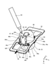
- Sectional drawing along the XIV-XIV line shown in FIG. A perspective view showing a protective case for a motor according to the first embodiment.
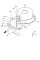
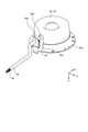
- Perspective view of the motor according to the first embodiment A perspective view showing a state in which the motor in the first embodiment is filled with a sealing material.
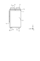
- FIG. 1 is an exploded perspective view showing a ventilation fan 100 according to the first embodiment.
- FIG. 2 is a perspective view showing an assembled state of the ventilation fan 100 shown in FIG. 1, and is a diagram showing a state in which the ventilation fan 100 is hung on a wall surface 30 of a building and installed.
- FIG. 3 is a perspective view showing a state in which the control board 15 is pulled out of the housing 1 from the ventilation fan 100 shown in FIG.
- FIG. 4 is a perspective view showing a state in which the filters 5, 6 and 7 and the filter lids 20, 21 and 22 are removed from the ventilation fan 100 shown in FIG. As shown in FIG.
- the ventilation fan 100 includes a housing 1, a heat exchange element 2, an air supply blower 3, an exhaust blower 4, an outside air filter 5, an exhaust filter 6, and an air supply filter 7. To prepare for. Further, the ventilation fan 100 includes an outdoor suction unit 8, an indoor suction unit 9, an indoor side outlet 10, an outdoor outlet 11, a drain pan 12, a drain port 13, an operation unit 14, and a control board. It is equipped with 15. The ventilation fan 100 is a device that ventilates the room while exchanging heat between the air from the outside and the air from the room. As shown in FIG. 2, the ventilation fan 100 is hung on the wall surface 30 of the building near the ceiling surface 31 and installed.
- the depth direction of the ventilation fan 100 is the X-axis direction
- the height direction of the ventilation fan 100 is the Y-axis direction
- the width direction of the ventilation fan 100 is the Z-axis direction.
- the + X-axis direction is the front
- the ⁇ X-axis direction is the rear.
- the + Y-axis direction is upward
- the ⁇ Y-axis direction is downward.
- the + Z axis direction is to the left and the ⁇ Z axis direction is to the right.
- the housing 1 is a box-shaped member constituting the outer shell of the ventilation fan 100.
- the shape of the housing 1 may be a cube, but in the present embodiment, it is a rectangular parallelepiped.
- the housing 1 has a top plate 1a, a bottom plate 1b, a front plate 1c, a back plate 1d, a left side plate 1e, and a right side plate 1f.
- the plate portion of the housing 1 in contact with the wall surface 30 is the back plate 1d
- the plate portion arranged on the opposite side of the back plate 1d from the wall surface 30 is the front plate 1c.
- the normal of the top plate 1a faces upward.
- the plan view shape of the top plate 1a is rectangular.
- the outdoor side suction portion 8, the indoor side suction portion 9, the indoor side blowout portion 10, and the outdoor side blowout portion 11 are provided on the top plate 1a.
- the outdoor suction unit 8 is a duct connection port for sucking air from the outside into the housing 1.
- a duct 27a connected to the outside is connected to the outdoor suction portion 8.
- the indoor suction unit 9 is a duct connection port for sucking air from the room into the housing 1.
- a duct 27b connected to the room is connected to the indoor suction portion 9.
- the indoor side blowing portion 10 is a duct connection port for blowing air from the outside to the outside of the housing 1.
- a duct 27c connected to the room is connected to the indoor side outlet portion 10.
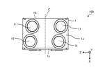
- FIG. 5 is a plan view of the ventilation fan 100 according to the first embodiment.
- the line extending in the direction perpendicular to the front plate 1c and the back plate 1d through the center of the top plate 1a in the Z-axis direction is referred to as the center line C.
- the indoor suction portion 9 and the indoor outlet 10 are arranged to the left of the center line C.
- the outdoor suction portion 8 and the outdoor outlet portion 11 are arranged to the right of the center line C.
- the outdoor suction portion 8 is arranged in front of the outdoor blowout portion 11.
- the indoor side blowing portion 10 is arranged in front of the indoor side suction portion 9.
- the outdoor suction portion 8 and the indoor blowout portion 10 are arranged at positions that coincide with each other in the X-axis direction.
- the indoor suction portion 9 and the outdoor blowout portion 11 are arranged at positions that coincide with each other in the X-axis direction.
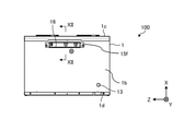
- FIG. 7 is a front view of the ventilation fan 100 according to the first embodiment.
- the normal of the front plate 1c faces the front, which is the front.
- the front plate 1c connects the front ends of the top plate 1a and the bottom plate 1b to each other.
- the front view shape of the front plate 1c is rectangular.
- the front plate 1c is formed with an outside air filter opening 17, an exhaust filter opening 18, and an air supply filter opening 19 that communicate the inside and the outside of the housing 1. Has been done.
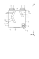
- FIG. 9 is a right side view of the ventilation fan 100 according to the first embodiment.
- the normal of the right plate 1f faces to the right.
- the right side plate 1f connects the right end portions of the top plate 1a and the bottom plate 1b to each other.
- the side view shape of the right side plate 1f is rectangular.
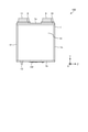
- the normal of the left plate 1e shown in FIG. 8 faces to the left.
- the left side plate 1e connects the left end portions of the top plate 1a and the bottom plate 1b to each other.
- the side view shape of the left side plate 1e is rectangular.
- FIG. 10 is a cross-sectional view taken along the line XX shown in FIG.
- the solid arrow X shown in FIG. 10 indicates the flow of air from the outside to the inside, that is, the flow of air supply.
- the broken line arrow Y shown in FIG. 10 indicates the flow of air from the room to the outside, that is, the flow of exhaust gas.
- the outdoor side suction portion 8 and the indoor side blowout portion 10 are not shown in cross section.
- an air supply air passage 23 for supplying air from the outside to the room and an exhaust air passage 24 for exhausting the air from the room to the outside are formed inside the housing 1, an air supply air passage 23 for supplying air from the outside to the room and an exhaust air passage 24 for exhausting the air from the room to the outside are formed.
- the air supply air passage 23 is an air passage that takes in outdoor air from the outdoor suction portion 8 into the housing 1 and supplies air from the indoor side outlet portion 10 toward the room.
- the exhaust air passage 24 is an air passage that takes in indoor air from the indoor side suction portion 9 into the housing 1 and exhausts it from the outdoor outlet portion 11 toward the outdoor side.
- the upstream side and the downstream side are based on the flow direction of the air flowing through the supply air passage 23 or the exhaust air passage 24.
- an outside air filter 5, a heat exchange element 2, and an air supply air blower 3 are arranged in order from the upstream side.
- a part of the air supply air passage 23 is formed of the heat insulating component 25 shown in FIG. 1 in order to suppress the occurrence of dew condensation.
- an exhaust filter 6, a heat exchange element 2, and an exhaust blower 4 are arranged in order from the upstream side.
- a part of the exhaust air passage 24 is formed of the heat insulating component 25 shown in FIG. 1 in order to suppress the occurrence of dew condensation.
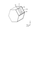
- FIG. 11 is a perspective view showing the heat exchange element 2 of the ventilation fan 100 according to the first embodiment.
- the shape of the heat exchange element 2 is not particularly limited as long as it is a polygonal column, but in the present embodiment, it is a hexagonal column.
- the heat exchange element 2 includes a plurality of partition members 2a arranged at intervals from each other, and a plurality of interval holding members 2b for maintaining the distance between the partition members 2a.
- the partition member 2a is formed in the form of a flatly processed sheet.
- the partition member 2a and the spacing member 2b are alternately laminated.
- An air passage is formed between the adjacent partition members 2a.
- the heat exchange element 2 is provided with air passages through which air from the outside flows and air passages through which air from the inside of the room flows alternately.
- the stacking direction which is the direction in which the partition member 2a and the spacing member 2b are laminated, coincides with the X-axis direction in the present embodiment, and is the direction perpendicular to the front plate 1c and the back plate 1d.
- the stacking direction may be a direction that coincides with the Y-axis direction and is perpendicular to the top plate 1a and the bottom plate 1b, or may be a direction that coincides with the Z-axis direction and is perpendicular to the left side plate 1e and the right side plate 1f.
- the heat exchange element 2 may be configured to be capable of both sensible heat exchange and latent heat exchange, or to be configured to be capable of either sensible heat exchange or latent heat exchange. May be good.
- the drain pan 12 is a member that is arranged below the heat exchange element 2 in the housing 1 and collects the drain water generated in the housing 1.
- the drain pan 12 is arranged on the bottom plate 1b.
- the control board 15 is arranged in the space 29 below the heat exchange element 2.
- the control board 15 is electrically connected to the operation unit 14 shown in FIG. 1 by a cable (not shown).
- the control board 15 has a first board 15a and a second board 15b.
- the first substrate 15a is a substrate connected to a power source (not shown).
- the first substrate 15a is housed in a box-shaped first substrate case 15c that opens downward.
- the second substrate 15b is a substrate having a connection unit, a control setting unit, and the like to which a sensor (not shown) is connected.
- the sensor connected to the second substrate 15b is, for example, a humidity sensor or a CO 2 sensor.
- the second substrate 15b is attached to the second substrate case 15d.
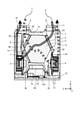
- FIG. 12 is a cross-sectional view taken along the line XII-XII shown in FIG.
- a rib 15e projecting forward or backward is formed at the upper end of the second substrate case 15d.
- a substrate lid 15f is attached to the lower end of the second substrate case 15d. When the second substrate case 15d and the second substrate 15b are inserted into the housing 1, the substrate lid 15f covers the substrate opening 16.
- the position fixing frame 26 is fitted in the opening 16 for the board.
- the positioning frame 26 has a first frame portion 26a, a second frame portion 26b, and a contact portion 26c.
- the first frame portion 26a is a square frame-shaped portion fitted into the first wall portion 16a.
- the second frame portion 26b is a square frame-shaped portion fitted into the second wall portion 16b.
- the opening area of the second frame portion 26b is larger than the opening area of the first frame portion 26a.
- the contact portion 26c is a flat portion connecting the upper end portion of the first frame portion 26a and the lower end portion of the second frame portion 26b.
- the contact portion 26c is arranged on the connecting wall portion 16c.
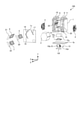
- the motor 32 is a device that rotates the blade 51.
- the type of the motor 32 is not particularly limited, but is, for example, a DC brushless motor.
- the motor 32 includes a motor housing 33, a stator 36, a rotor 37, a shaft 38, a first bearing 39, a second bearing 40, a circuit board 41, a protective cover 43, and a protective case 44. To prepare for.
- the direction parallel to the central axis P of the motor 32 is the axial direction
- the direction orthogonal to the central axis P of the motor 32 is the radial direction
- the central axis P of the motor 32 is referred to.
- the direction of rotation around the center is the circumferential direction.
- the axial and x m-axis direction a direction orthogonal to the x m-axis direction and y m-axis direction, a direction orthogonal to the x m-axis direction and the y m-axis direction and z m-axis direction.
- y m-axis direction is one direction orthogonal to the x m-axis direction, a direction included in the radial direction.
- z m-axis direction is one direction orthogonal to the x m-axis direction, a direction included in the radial direction.
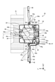
- the motor housing 33 is a hollow member that houses the stator 36, the rotor 37, the first bearing 39, the second bearing 40, and the circuit board 41.
- the motor housing 33 has a frame 34 and a bracket 35.
- the material of the frame 34 and the bracket 35 is metal.
- Each of the frame 34 and the bracket 35 is formed in a bottomed cylindrical shape in which one end is opened along the xm axis direction.
- the frame 34 and the bracket 35 are arranged so that the openings face each other.
- a flange-shaped frame flange 34a extending radially outward is formed at the opening edge of the frame 34.
- a flange-shaped bracket flange 35a extending radially outward is formed at the opening edge of the bracket 35.
- the frame flange 34a and the bracket flange 35a are fixed to each other with screws 49 and 50 in a state of being overlapped with each other.
- a first bearing housing 34b for holding the first bearing 39 is formed on the bottom wall of the frame 34.
- An insertion hole 34c through which the shaft 38 is inserted is formed in the bottom wall of the frame 34 radially inside the first bearing housing 34b.
- a second bearing housing 35b for holding the second bearing 40 is formed on the bottom wall of the bracket 35.
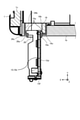
- a first through hole 35c for pulling out the lead wire 42 to the outside of the motor housing 33 is formed on the side wall of the bracket 35.
- the first through hole 35c is formed so as to penetrate a part of the side wall including the bracket flange 35a.
- the stator 36 is a cylindrical member arranged inside the motor housing 33.
- the stator 36 is press-fitted into the frame 34 and the bracket 35.
- the stator 36 has an iron core 36a and a coil 36b wound around the iron core 36a.
- the rotor 37 is a cylindrical member arranged inside the stator 36.
- the rotor 37 rotates about the shaft 38.
- a gap (not shown) is provided between the stator 36 and the rotor 37 over the entire circumference.
- the shaft 38 is a member connected to the rotor 37. Although the shaft 38 is integrally formed with the rotor 37 in this embodiment, it may be formed separately from the rotor 37.
- One end 38a along the axial direction of the shaft 38 projects to the outside of the motor housing 33 through the insertion hole 34c.
- a blade 51 is attached to one end 38a of the shaft 38.
- the other end 38b along the axial direction of the shaft 38 is located inside the bracket 35.
- the circuit board 41 is a board that is arranged inside the motor housing 33 and controls the rotor 37.
- the circuit board 41 is arranged in a space formed between the rotor 37 and the bottom wall of the bracket 35. Power is supplied to the circuit board 41 via the lead wire 42.
- the lead wire 42 is connected to a circuit board 41 and an external power supply (not shown).
- the lead wire 42 passes through the first through hole 35c formed in the side wall of the bracket 35 and is pulled out to the outside of the motor housing 33.
- the plurality of lead wires 42 are covered with a tubular lead tube 45. Thereby, the lead wire 42 can be protected.
- the lead wire 42 means the lead wire 42 in a state of being covered with the lead tube 45.
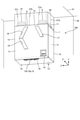
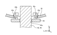
- the base portion 44a is a portion separated from the protective cover 43.
- a space 46 is provided between the base 44a and the protective cover 43.
- the space 46 is filled with a sealing material 47.
- the sealing material 47 is, for example, a waterproof resin.
- a third through hole 44d through which the lead wire 42 can pass is formed in the base portion 44a.
- the lead wire 42 passes through the first through hole 35c, the second through hole 43a, and the third through hole 44d, and is led out to the outside of the motor housing 33.
- the first through hole 35c, the second through hole 43a, and the third through hole 44d are holes, notches, and the like.
- the third through hole 44d is provided at one end of the base 44a along the xm axis direction.
- Third through hole 44d is open to one along the x m-axis direction.
- the base portion 44a is formed with a holding projection 44e that projects inward from the inner wall of the third through hole 44d to hold the lead wire 42.
- the portion of the third through hole 44d in which the holding protrusion 44e is formed has the narrowest opening width.
- the opening width of the holding protrusion 44e is smaller than the diameter of the lead tube 45.
- confirmation holes 44f that can confirm the filling amount of the sealing material 47 in the space 46 are formed one by one.
- the shape of the confirmation hole 44f which is the internal confirmation portion, is not particularly limited, but is generally oval in the present embodiment.
- bent portion 44g is formed. As shown in FIG. 13, the bent portion 44g is bent so as to be located radially inwardly toward the other from the one along the x m-axis direction. The tip of the bent portion 44 g is in contact with the bottom wall of the bracket 35. As shown in FIG.
- the bent portion 44g is formed with a filling hole 44h for filling the space 46 with the sealing material 47.
- the shape of the filling hole 44h is not particularly limited, but is U-shaped in the present embodiment.
- Fill hole 44h is opened at the other along the x m-axis direction of the bent portion 44 g.
- Fill hole 44h, in the x m-axis direction, are formed on the opposite side of the third through hole 44d and the confirmation holes 44f.
- fill hole 44h, the second through-hole 43a it is disposed on the -x m side of the x m-axis than the third through hole 44d and the confirmation holes 44f.
- the second through-hole 43a is disposed on the -x m side of the x m-axis than the third through hole 44d and the confirmation holes 44f.
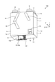
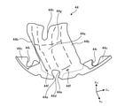
- the two contact portions 44b are portions that can contact the side wall of the bracket 35.
- the contact portion 44b extends parallel to the base portion 44a.
- the base portion 44a is separated from the protective cover 43 in a state where the contact portion 44b is in contact with the side wall of the bracket 35.
- the protective case flange 44c extends along the y m-axis direction from one end along the x m-axis direction of the base portion 44a and contact portion 44b.
- the protective case flange 44c is formed with a screw notch 44i for passing a screw 49, which will be described later.
- the motor 32 is fixed to the rectangular frame-shaped motor fixing portion 48 with screws 49 and 50.
- the motor 32 is arranged inside the motor fixing portion 48.
- a flange 48a on the motor fixing portion side that supports the motor 32 is formed on the inner surface of the motor fixing portion 48 facing the motor 32.
- the motor fixing portion side flange 48a is formed in an arc shape along the outer peripheral shape of the motor housing 33.
- the protective case flange 44c, the frame flange 34a, the bracket flange 35a, and the motor fixing portion side flange 48a are co-tightened with screws 49 in a state of being overlapped with each other.
- the protective case 44 is fixed to the frame flange 34a, the bracket flange 35a, and the motor fixing portion side flange 48a. Further, in the position where the protective case flange 44c does not exist, the frame flange 34a, the bracket flange 35a, and the motor fixing portion side flange 48a are co-tightened with screws 50 in a state of being overlapped with each other.
- a first through hole 35c for pulling out the lead wire 42 to the outside of the motor housing 33 is formed on the side wall of the bracket 35.
- the motor 32 has a protective cover 43 which is attached so as to cover the first through hole 35c and has a second through hole 43a through which the lead wire 42 can pass, and a third through hole 43a through which the lead wire 42 can pass.
- the through hole 44d is formed and includes a protective cover 43 and a protective case 44 that covers the lead wire 42. Further, a space 46 is provided between the protective case 44 and the protective cover 43, and the space 46 is filled with the sealing material 47.
- the sealing material 47 can prevent moist air from entering the inside of the motor 32 through the third through hole 44d and the first through hole 35c. Therefore, dew condensation is less likely to occur inside the motor 32. Therefore, the ventilation fan 100 provided with the motor 32 can be used for ventilation in a high humidity atmosphere.
- the high humidity atmosphere is, for example, the air in the bathroom.
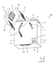
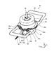
- the nozzle of the container 52 in which the sealing material 47 made of waterproof resin is sealed is positioned in the filling hole 44h, and the sealing material 47 is placed in the space 46 from the container 52 through the filling hole 44h.
- the motor 32 is arranged so as to be. Further, when the sealing material 47 is filled, as shown in FIG. 18, the position of the second through hole 43a in the vertical direction is higher than the positions of the third through hole 44d and the confirmation hole 44f in the vertical direction.
- the motor 32 shown in FIG. 17 is arranged.
- the first through hole 35c shown in FIG. 18 is largely closed by the protective cover 43 and the lead wire 42, but is shown in FIG. 14 in order to allow the lead wire 42 to pass through the second through hole 43a of the protective cover 43.
- the inner diameter of the second through hole 43a is formed to be slightly larger than the outer diameter of the lead wire 42. As a result, a fine gap is formed between the inner wall of the second through hole 43a and the outer peripheral surface of the lead wire 42.
- a confirmation hole 44f is provided in the present embodiment, and when the sealing material 47 is filled, the confirmation hole 44f is provided.
- the protective case 44 is formed with a filling hole 44h for filling the space 46 with the sealing material 47, so that the container for filling the sealing material 47 is formed. Since the alignment of the nozzles of the 52 is facilitated, the workability when filling the sealing material 47 can be improved. Further, in the present embodiment, as shown in FIG. 17, the protective case 44 is formed with a confirmation hole 44f at which the filling amount of the sealing material 47 can be confirmed, so that the filling work of the sealing material 47 is stopped. It becomes easy to determine the timing of the sealing material 47, and the filling amount of the sealing material 47 can be adjusted to an appropriate amount.
- the protective case 44 is formed with a holding protrusion 44e that protrudes from the inner wall of the third through hole 44d and holds the lead wire 42, whereby the lead wire 42 is formed. Can be fixed.
- the movement of the lead wire 42 can be suppressed until the liquid sealing material 47 filled in the third through hole 44d is solidified, so that a gap is unlikely to occur between the lead wire 42 and the sealing material 47. Therefore, since moist air can be further prevented from entering the inside of the motor 32, dew condensation is less likely to occur inside the motor 32. Further, since the movement of the lead wire 42 can be suppressed until the liquid sealing material 47 filled in the third through hole 44d is solidified, the workability when filling the sealing material 47 can be improved.
- the sealing material 47 shown in FIG. 13 is a waterproof resin, it is possible to further prevent moist air from entering the inside of the motor 32, so that dew condensation is further generated inside the motor 32. It becomes difficult to do.
- the protective case 44 shown in FIG. 13 is an integral body, the arrangement of the protective case 44, the protective cover 43, and the lead wire 42 can be easily determined, so that the assembly work is easy. Become.
- the confirmation hole 44f is provided as a means for confirming the filling amount of the sealing material 47, but a part or all of the protective case 44 is made transparent or translucent, and the inside of the protective case 44 is made transparent or translucent. You may be able to confirm.
- the transparent portion or the translucent portion of the protective case 44 serves as an internal confirmation portion where the filling amount of the sealing material 47 can be confirmed.
- the protective case 44 is fixed to the frame flange 34a, the bracket flange 35a, and the motor fixing portion side flange 48a with screws 49, but the fixing location of the protective case 44. It is not intended to limit.
- the protective case 44 may be fixed only to the frame 34 or may be fixed only to the bracket 35.
- screw holes are provided in the contact portion 44b of the protective case 44 shown in FIG. 17 that comes into contact with the side wall of the bracket 35 and the side wall of the bracket 35. Screws can be screwed into both screw holes.
- the configuration shown in the above embodiment is an example, and can be combined with another known technique, or a part of the configuration may be omitted or changed without departing from the gist. It is possible.
Landscapes
- Engineering & Computer Science (AREA)
- Power Engineering (AREA)
- Motor Or Generator Frames (AREA)
Priority Applications (2)
| Application Number | Priority Date | Filing Date | Title |
|---|---|---|---|
| PCT/JP2020/027890 WO2022014049A1 (ja) | 2020-07-17 | 2020-07-17 | モータおよび換気扇 |
| JP2022536100A JP7292519B2 (ja) | 2020-07-17 | 2020-07-17 | モータおよび換気扇 |
Applications Claiming Priority (1)
| Application Number | Priority Date | Filing Date | Title |
|---|---|---|---|
| PCT/JP2020/027890 WO2022014049A1 (ja) | 2020-07-17 | 2020-07-17 | モータおよび換気扇 |
Publications (1)
| Publication Number | Publication Date |
|---|---|
| WO2022014049A1 true WO2022014049A1 (ja) | 2022-01-20 |
Family
ID=79554535
Family Applications (1)
| Application Number | Title | Priority Date | Filing Date |
|---|---|---|---|
| PCT/JP2020/027890 Ceased WO2022014049A1 (ja) | 2020-07-17 | 2020-07-17 | モータおよび換気扇 |
Country Status (2)
| Country | Link |
|---|---|
| JP (1) | JP7292519B2 (enExample) |
| WO (1) | WO2022014049A1 (enExample) |
Citations (3)
| Publication number | Priority date | Publication date | Assignee | Title |
|---|---|---|---|---|
| JPH08285347A (ja) * | 1995-04-14 | 1996-11-01 | Toshiba Corp | 天井用換気扇 |
| JP2004064849A (ja) * | 2002-07-26 | 2004-02-26 | Mitsubishi Electric Corp | モーター及び送風機 |
| JP2012253845A (ja) * | 2011-05-31 | 2012-12-20 | Mitsubishi Electric Corp | 電動機および換気扇 |
-
2020
- 2020-07-17 WO PCT/JP2020/027890 patent/WO2022014049A1/ja not_active Ceased
- 2020-07-17 JP JP2022536100A patent/JP7292519B2/ja active Active
Patent Citations (3)
| Publication number | Priority date | Publication date | Assignee | Title |
|---|---|---|---|---|
| JPH08285347A (ja) * | 1995-04-14 | 1996-11-01 | Toshiba Corp | 天井用換気扇 |
| JP2004064849A (ja) * | 2002-07-26 | 2004-02-26 | Mitsubishi Electric Corp | モーター及び送風機 |
| JP2012253845A (ja) * | 2011-05-31 | 2012-12-20 | Mitsubishi Electric Corp | 電動機および換気扇 |
Also Published As
| Publication number | Publication date |
|---|---|
| JP7292519B2 (ja) | 2023-06-16 |
| JPWO2022014049A1 (enExample) | 2022-01-20 |
Similar Documents
| Publication | Publication Date | Title |
|---|---|---|
| KR101340835B1 (ko) | 열교환 환기 장치 | |
| CN103026142A (zh) | 顶棚埋入式换气扇 | |
| JP2012154527A (ja) | 天井埋込形換気扇 | |
| WO2020039633A1 (ja) | 天井埋込型空気調和機 | |
| JP4945357B2 (ja) | 天井埋込型空気調和装置の室内機 | |
| JP2004085003A (ja) | 空気調和機の室内機 | |
| KR100297176B1 (ko) | 천정용환기팬 | |
| WO2022014049A1 (ja) | モータおよび換気扇 | |
| KR100709465B1 (ko) | 공기 조화기의 실외기 | |
| JP2020030026A (ja) | 天井埋込型空気調和機 | |
| JP6097931B2 (ja) | 熱交換形換気装置 | |
| JP5516495B2 (ja) | 天井埋込型空気調和装置の室内機 | |
| JP2776736B2 (ja) | パイプ用ファン | |
| WO2021014491A1 (ja) | 熱交換型換気装置 | |
| WO2020039634A1 (ja) | 空気調和機 | |
| JP2001065924A (ja) | 空気調和機の室外ユニット | |
| KR100582458B1 (ko) | 환기장치 | |
| WO2010109652A1 (ja) | 熱交換換気装置 | |
| CN223689962U (zh) | 轴流风扇及具有其的除湿机 | |
| JP6674153B2 (ja) | 天井埋込型空気調和機 | |
| JP2024119651A (ja) | 埋込形換気扇 | |
| JP5205493B2 (ja) | 天井埋込型空気調和装置の室内機 | |
| JP5232667B2 (ja) | 天井埋込型空気調和装置 | |
| JPH0271029A (ja) | 熱交換ユニット | |
| JP4397789B2 (ja) | 空気調和機の室外機 |
Legal Events
| Date | Code | Title | Description |
|---|---|---|---|
| 121 | Ep: the epo has been informed by wipo that ep was designated in this application |
Ref document number: 20945371 Country of ref document: EP Kind code of ref document: A1 |
|
| ENP | Entry into the national phase |
Ref document number: 2022536100 Country of ref document: JP Kind code of ref document: A |
|
| NENP | Non-entry into the national phase |
Ref country code: DE |
|
| 122 | Ep: pct application non-entry in european phase |
Ref document number: 20945371 Country of ref document: EP Kind code of ref document: A1 |