WO2022013931A1 - 光ファイバスイッチ - Google Patents
光ファイバスイッチ Download PDFInfo
- Publication number
- WO2022013931A1 WO2022013931A1 PCT/JP2020/027302 JP2020027302W WO2022013931A1 WO 2022013931 A1 WO2022013931 A1 WO 2022013931A1 JP 2020027302 W JP2020027302 W JP 2020027302W WO 2022013931 A1 WO2022013931 A1 WO 2022013931A1
- Authority
- WO
- WIPO (PCT)
- Prior art keywords
- optical fiber
- core
- cores
- optical
- head
- Prior art date
- Legal status (The legal status is an assumption and is not a legal conclusion. Google has not performed a legal analysis and makes no representation as to the accuracy of the status listed.)
- Ceased
Links
Images





Classifications
-
- G—PHYSICS
- G02—OPTICS
- G02B—OPTICAL ELEMENTS, SYSTEMS OR APPARATUS
- G02B6/00—Light guides; Structural details of arrangements comprising light guides and other optical elements, e.g. couplings
- G02B6/24—Coupling light guides
- G02B6/26—Optical coupling means
- G02B6/35—Optical coupling means having switching means
-
- G—PHYSICS
- G02—OPTICS
- G02B—OPTICAL ELEMENTS, SYSTEMS OR APPARATUS
- G02B6/00—Light guides; Structural details of arrangements comprising light guides and other optical elements, e.g. couplings
- G02B6/24—Coupling light guides
- G02B6/36—Mechanical coupling means
- G02B6/38—Mechanical coupling means having fibre to fibre mating means
Definitions
- the present disclosure relates to an optical fiber switch in which one of a plurality of optical fibers is selected and connected.
- the optical access system connects the OLT (Optical Line Thermal) in the communication equipment building and the ONU (Optical Network Unit) on the user side with an optical fiber. These optical fibers are monitored and measured by OTM (Optical Testing Module) from the communication equipment building.
- OLT Optical Line Thermal
- ONU Optical Network Unit
- OTM Optical Testing Module
- Fig. 1 shows the monitoring / measurement system of the related optical fiber
- Fig. 2 shows the configuration of the related optical switch used in the monitoring / measurement system.
- 71 is a V-groove substrate
- 72 is a tape optical fiber
- 73 is an optical fiber array
- 74 is a head optical fiber
- 78 is an optical coupler
- 80 is an optical switch
- 91 is a communication equipment building
- 92 is an operation.
- the terminal 93 is an OTM
- 94 is a tape optical fiber
- 95 is an OLT
- 96 is an ONU.
- the OTM93 is composed of an optical measuring instrument such as an OTDR (Optical Time Domain Reflectometer), a light source for controlling a core wire of an optical fiber, and a controller for controlling these.
- the OTDR test light and the core wire control light of the core wire control light source are transmitted from the OTM 93 to the tape optical fiber 94 via the optical switch 80 and the optical coupler 78 (see, for example, Non-Patent Document 1).
- the OLT 95 in the communication equipment building 91 and the ONU 96 on the user side are connected by an optical fiber, for example, a tape optical fiber 94, and input / output of test light and core wire control light for monitoring and measuring the tape optical fiber 94. Therefore, the optical coupler 78 is inserted in the tape optical fiber 94.
- the optical switch 80 connects the head optical fiber 74 from the OTM 93 and the tape optical fiber 72 from the optical coupler 78.
- the optical switch 80 is an optical fiber array 73 in which tape optical fibers 72 are arranged on a V-groove substrate 71 for each core wire, and one head optical fiber 74 and a head optical fiber 74 are arranged in the X-axis direction and the Y-axis. It is equipped with a connection circuit (not shown) that moves in the direction. The operator operates the operation terminal 92, and the connection circuit moves the head optical fiber 74 in the X-axis direction and the Y-axis direction to connect the head optical fiber 74 from the OTM 93 and the tape optical fiber 72 from the optical coupler 78. (For example, refer to Patent Documents 1 to 3).
- the optical coupler 78 is coupled in two directions, an up direction and a down direction, of the tape optical fiber 72.
- JP-A-9-80329 Japanese Patent Application Laid-Open No. 10-123439 JP 2009-10978
- the number of optical fibers accommodated in the communication equipment building 91 is increasing year by year. Since each optical terminal rack can accommodate a maximum of 4000 cores, the scale of the optical switch 80 is 8000 cores of optical fibers in the ascending direction and the descending direction.
- the optical switch 80 requires a wide optical fiber array in which 8000 core optical fibers are arranged on a V-groove substrate 71.
- the optical switch provided with the 8000-core optical fiber array becomes large, and it becomes difficult to transport and accommodate the optical switch 80 and the tape optical fiber 72 to the optical termination rack.
- the number of parts of the optical switch 80 and the tape optical fiber 72 increases and the size of the V-groove substrate 71 and the connection circuit increases, there are major problems in manufacturability and cost.
- the moving distance of the head optical fiber 74 becomes long, so that it takes time to access the optical switch 80 at the time of monitoring / measurement by the OTM 93, and it takes time to operate the operation terminal 92.
- the problem of need arises.
- the present disclosure aims to provide a miniaturized optical fiber switch.
- the optical fiber switch according to the present disclosure is configured to select a multi-core optical fiber and connect the core of the single-core optical fiber to one of the plurality of cores of the selected multi-core optical fiber.
- the optical fiber switch according to the present disclosure is A first optical fiber array in which a plurality of multi-core optical fibers having N cores (N is a positive integer of 2 or more) are arranged on a V-groove substrate.
- a multi-core head optical fiber using a multi-core optical fiber having N cores One multi-core optical fiber is selected from the plurality of multi-core optical fibers of the first optical fiber array, and the multi-core head optical fiber is attached to N cores at one end of the selected one multi-core optical fiber. It is provided with a multi-core connection circuit for connecting each of the N cores at one end of the above.
- the optical fiber switch according to the present disclosure is A first optical fiber array in which a plurality of multi-core optical fibers having N cores (N is a positive integer of 2 or more) are arranged on a V-groove substrate.
- a second single-core head optical fiber using one single-core optical fiber, and One multi-core optical fiber is selected from the plurality of the multi-core optical fibers of the first optical fiber array, and the second single is attached to one core at one end of the selected one multi-core optical fiber.
- a second single-core connection circuit for connecting the cores at one end of the core head optical fiber is provided.
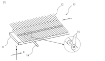
- FIG. 3 is a V-groove substrate, 12 is a multi-core optical fiber, 13 is a first optical fiber array, 14 is a multi-core head optical fiber, and 16 is a core of a multi-core optical fiber 12 or a multi-core head optical fiber 14.
- the optical fiber switch is a first optical fiber array 13 in which a plurality of multi-core optical fibers 12 having N cores (N is a positive integer of 2 or more; the same applies hereinafter) are arranged on a V-groove substrate 11.
- One multi-core optical fiber is selected from the multi-core optical fiber 14 using the multi-core optical fiber having N cores and the plurality of multi-core optical fibers 12 of the first optical fiber array 13.
- a multi-core connection circuit (not shown) for connecting the N cores at one end of the multi-core head optical fiber 14 to the N cores at one end of the one multi-core optical fiber is provided.
- the multi-core optical fiber 12 and the multi-core head optical fiber 14 each have N cores 16.
- the multi-core head optical fiber 14 is moved in the X-axis and Y-axis directions by a ball screw, a motor, or the like, and one end of the multi-core head optical fiber 14 is connected to a plurality of multi-core optical fibers of the first optical fiber array 13. It is connected to one end of one multi-core optical fiber from the fiber 12.
- the X-axis direction is the arrangement direction of the first optical fiber array 13 in the plane perpendicular to the long axis of the multi-core optical fiber 12.
- the Y-axis direction is a direction perpendicular to the arrangement direction of the first optical fiber array 13 in a plane perpendicular to the long axis of the multi-core optical fiber 12. It is desirable that the multi-core optical fiber 12 and the multi-core head optical fiber 14 have the same outer diameter and the same arrangement of N cores.
- the multi-core optical fiber 12 and the multi-core head optical fiber 14 have N cores at one end of the multi-core optical fiber 12 and N cores at one end of the multi-core optical fiber 14 when the core positions are aligned in advance. It is easy to connect each of the cores.
- N is illustrated as 4.
- the optical fiber switch of the present disclosure uses a 4-core multi-core optical fiber
- the number of grooves of the V-groove substrate 11 and the number of arrays of the first optical fiber array 13 are related technologies even if the scale is 8000 cores. It is 2000, which is a quarter of the optical fiber switch.
- the optical fiber switch can be miniaturized, and further, it is excellent in manufacturability, cost, and transportability.
- the width of the V-groove substrate is narrowed, the moving distance of the multi-core head optical fiber in the X-axis direction is shortened, and the access time of the optical fiber switch is shortened when the optical fiber switch is replaced.
- the number of cores of the multi-core optical fiber 12 is 4, but when the number of cores is N, the number of grooves of the V-groove substrate 11 and the number of arrays of the first optical fiber array 13 are N minutes. It becomes 1.
- 14 is a multi-core optical fiber
- 20 is a single-core optical fiber
- 21 is a first fanout
- 22 is a V-groove substrate
- 23 is a second optical fiber array
- 24 is a first single. It is a core head optical fiber.
- the optical fiber switch of the present disclosure has a first fan-out 21 that converts N cores at the other end of the multi-core head optical fiber 14 into N single-core optical fibers 20 and a first on a V-groove substrate 22.
- a second optical fiber array 23 in which N single-core optical fibers 20 from the fan-out 21 of the above are arranged, a first single-core head optical fiber 24 using one single-core optical fiber, and a second.
- One single-core optical fiber is selected from the N single-core optical fibers 20 of the optical fiber array 23, and the first single-core head optical fiber 24 is used as the core at one end of the selected single-core optical fiber.
- a first single-core connection circuit (not shown) for connecting the cores at one end of each of the above is further provided.
- the first fan-out 21 converts the N cores at the other end of the multi-core head optical fiber 14 having N cores into N single-core optical fibers 20.
- the first single-core head optical fiber 24 is moved in the X-axis and Y-axis directions by a ball screw, a motor, or the like, and the first single-core head optical fiber 24 is moved. Is connected to one end of one single core optical fiber in the plurality of single core optical fibers 20 of the second optical fiber array 23.
- the X-axis direction is the arrangement direction of the second optical fiber array 23 in the plane perpendicular to the long axis of the single core optical fiber 20.
- the Y-axis direction is a direction perpendicular to the arrangement direction of the second optical fiber array 23 in a plane perpendicular to the long axis of the single core optical fiber 20. It is desirable that the single core optical fiber 20 and the first single core head optical fiber 24 have the same outer diameter and the core is arranged in the center.
- the number of arrays of the second optical fiber array 23 is set to 4, but the first optical fiber Assuming that the number of cores of the multi-core optical fiber 12 and the multi-core head optical fiber 14 constituting the array 13 is N, the number of arrays of the second optical fiber array 23 is N.
- the optical fiber switch of the present disclosure can select any core of any multi-core optical fiber from a plurality of multi-core optical fibers having N cores.
- the optical fiber switch of the present disclosure converts N cores of the multi-core optical fiber 12 into N single-core optical fibers at the other end of each of the plurality of multi-core optical fibers 12 from the first optical fiber array 13.
- a second fan-out 26 may be further provided. The configuration of the second fanout is shown in FIG. In FIG. 6, 12 is a multi-core optical fiber, 25 is a single-core optical fiber, 26 is a second fan-out, 27 is a single-core optical fiber, and 29 is a multi-core optical fiber connector.
- the second fan-out 26 converts the four single-core optical fibers 25 into the multi-core optical fiber 12 having four cores.
- the converted multi-core optical fiber 12 is arranged in the V-groove of the first optical fiber array 13.
- the second fan-out 26 may include a multi-optical fiber connector 29 on the premise of a tape optical fiber in which four single-core optical fibers 25 are put together.
- the multi-optical fiber connector 29 connects the single-core optical fiber 25 and the single-core optical fiber 27.
- the number of cores of the multi-core optical fiber 12 and the multi-core head optical fiber 14 constituting the first optical fiber array 13 is 4, the number of conversions of the second fan out 26 is set to 4, but the first optical fiber array. Assuming that the number of cores of the multi-core optical fiber 12 and the multi-core head optical fiber 14 constituting the 13 is N, the conversion number of the second fan-out 26 is N.
- FIG. 7 shows an optical fiber monitoring / measurement system to which the optical fiber switch of the present disclosure is applied.
- 11 is a V-groove substrate
- 12 is a multi-core optical fiber
- 14 is a multi-core head optical fiber
- 20 is a single-core optical fiber
- 21 is a first fan-out
- 22 is a V-groove substrate
- 24 is a first single.
- 25 is a single core optical fiber
- 26 is a second fan out
- 28 is an optical coupler
- 29 is a multi-optical fiber connector
- 51 is a communication equipment building
- 52 is an operation terminal
- 53 is an OTM
- 54 is a tape.
- 55 is OLT
- 56 is ONU.
- An optical fiber is used to connect the OLT (Optical Line Thermal) 55 in the communication equipment building 51 and the ONU (Optical Network Unit) 56 on the user side.
- the tape optical fiber 54 is exemplified here. These optical fibers are monitored and measured by an OTM (Optical Testing Module) 53 from a communication equipment building.
- the OTM53 is composed of an OTDR (Optical Time Domain Reflectometer), an optical measuring instrument such as a light source for core wire control of an optical fiber, and a controller for controlling these.
- An optical coupler 28 is inserted into the tape optical fiber 54 for input / output of test light and core wire control light for monitoring and measuring the tape optical fiber 54.
- the optical fiber switch of the present disclosure includes the first single core head optical fiber 24 from the OTM 53 and the single core optical fiber 25 from the optical coupler 28. To connect.
- the second fan-out 26 converts a plurality of single-core optical fibers 25 into a multi-core optical fiber 12 having N cores.
- the multi-core connection circuit (not shown) selects one multi-core optical fiber from the plurality of multi-core optical fibers 12 on the V-groove substrate 11 and connects it to the multi-core head optical fiber 14.
- the first fanout 21 converts the multi-core head optical fiber 14 into N single-core optical fibers 20.
- the first single-core connection circuit selects one single-core optical fiber from the plurality of single-core optical fibers 20 on the V-groove substrate 22, and the first single-core head optical fiber 24 Connect with. Either the multi-core connection circuit or the first single-core connection circuit may operate first, or may operate at the same time.
- any single-core optical fiber can be connected to the first single-core head optical fiber 24 from among the plurality of single-core optical fibers 25.
- the optical coupler 28 and the optical fiber switch can be connected by a multi-core optical fiber, so that the number of optical fibers can be reduced and the accommodation of the optical fiber can be improved. Contribute to.
- the optical fiber switch of the present disclosure includes a first optical fiber array in which a plurality of multi-core optical fibers having N cores (N is a positive integer of 2 or more) are arranged on a V-groove substrate, and one single core.
- One multi-core optical fiber is selected from the second single-core head optical fiber using an optical fiber and the plurality of multi-core optical fibers of the first optical fiber array, and the selected one multi-core optical fiber is used.
- a second single-core connection circuit for connecting the core at one end of the second single-core head optical fiber to one core at one end is provided.
- the optical fiber switch of the present disclosure can select any core of any multi-core optical fiber from a plurality of multi-core optical fibers having N cores.
- 11 is a V-groove substrate
- 12 is a multi-core optical fiber
- 13 is a first optical fiber array
- 34 is a second single-core head optical fiber
- 35 is a second single-core connection circuit
- 36 is a multi-core optical fiber.
- the optical fiber switch of the present disclosure includes a first optical fiber array 13 in which a plurality of multi-core optical fibers 12 having N cores (N is a positive integer of 2 or more) are arranged on a V-groove substrate 11. 1 multi-core optical fiber was selected from the second single-core head optical fiber 34 using the single-core optical fiber of No. 1 and the plurality of multi-core optical fibers 12 of the first optical fiber array 13.
- a second single-core connection circuit 35 for connecting the core at one end of the second single-core head optical fiber 34 to one core at one end of the multi-core optical fiber of the book is provided.
- N cores are arranged concentrically at a predetermined distance from the center, and in the second single core head optical fiber 34, one core is the same predetermined distance from the center. It is located at the position of. It is preferable to fill the space between the multi-core optical fiber 12 and the second single-core head optical fiber 34 with a refractive index matching material in order to suppress reflection.
- the second single-core connection circuit 35 moves the second single-core head optical fiber 34 in the X-axis and Y-axis directions with a ball screw, a motor, or the like, and connects one end of the second single-core head optical fiber 34.
- the X-axis direction is the arrangement direction of the first optical fiber array 13 in the plane perpendicular to the long axis of the multi-core optical fiber 12.
- the Y-axis direction is a direction perpendicular to the arrangement direction of the first optical fiber array 13 in a plane perpendicular to the long axis of the multi-core optical fiber 12. It is desirable that the multi-core optical fiber 12 and the second single-core head optical fiber 34 have the same outer diameter.
- the second single-core connection circuit 35 further rotates the second single-core head optical fiber 34 so that the second single-core head optical fiber is connected to one core at one end of one selected multi-core optical fiber 12.
- the core at one end of the fiber 34 is connected.
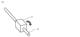
- FIG. 9 shows the rotation of the second single core connection circuit 35.
- 34 is a second single-core head optical fiber
- 35 is a second single-core connection circuit.
- the second single-core connection circuit 35 rotates the second single-core head optical fiber 34 around its long axis to form a core of one of the N cores at one end of the multi-core optical fiber 12.
- 2 Single core head Connects the core at one end of the optical fiber 34.
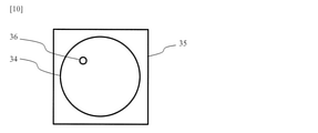
- FIG. 10 shows a cross-sectional view of the second single core connection circuit 35 perpendicular to the long axis of the second single core head optical fiber 34.
- 34 is a second single-core head optical fiber
- 35 is a second single-core connection circuit
- 36 is a core.
- the second single-core connection circuit 35 rotates the core 36 about the long axis of the second single-core head optical fiber 34.
- FIG. 11 shows a situation in which the second single-core head optical fiber 34 is rotated and the core at one end of the second single-core head optical fiber 34 is connected to one core at one end of the multi-core optical fiber 12.
- (a) is the end face of one end of the multi-core optical fiber 12
- (b), (c), (d) and (e) are the same as (a) at one end of the second single-core head optical fiber 34. It is the end face seen from the direction.
- the second single core head optical fiber 34 is rotated to the position (b).
- the second single core head optical fiber 34 is rotated to the position (c).
- the second single core head optical fiber 34 is rotated to the position (d).
- the second single-core head optical fiber 34 is rotated to the position (e).
- the optical fiber switch of the present disclosure can select and connect any core of any multi-core optical fiber from a plurality of multi-core optical fibers having N cores. can.
- the optical fiber switch of the present disclosure uses a 4-core multi-core optical fiber
- the number of grooves of the V-groove substrate 11 and the number of arrays of the first optical fiber array 13 are related technologies even if the scale is 8000 cores. It is 2000, which is a quarter of the optical fiber switch.
- the optical fiber switch can be miniaturized, and further, it is excellent in manufacturability, cost, and transportability.
- the width of the V-groove substrate is narrowed, the moving distance of the multi-core head optical fiber in the X-axis direction is shortened, and the access time of the optical fiber switch is shortened when the optical fiber switch is replaced.
- the number of cores of the multi-core optical fiber 12 is 4, but when the number of cores is N, the number of grooves of the V-groove substrate 11 and the number of arrays of the first optical fiber array 13 are N minutes. It becomes 1.
- the optical fiber switch of the present disclosure converts N cores of the multi-core optical fiber 12 into N single-core optical fibers at the other end of each of the plurality of multi-core optical fibers 12 from the first optical fiber array 13.
- a second fan-out 26 may be further provided. The configuration of the second fanout 26 is the same as that of the first embodiment.
- the optical fiber switch connected to one single-core optical fiber from among the plurality of single-core optical fibers can be miniaturized.
- FIG. 12 shows an optical fiber monitoring / measurement system to which the optical fiber switch of the present disclosure is applied.
- 11 is a V-groove substrate
- 12 is a multi-core optical fiber
- 13 is a first optical fiber array
- 25 is a single-core optical fiber
- 26 is a second fan out
- 28 is an optical coupler
- 29 is a multi-optical fiber.
- Connector, 34 is the second single core head optical fiber
- 35 is the second single core connection circuit
- 51 is the communication equipment building
- 52 is the operation terminal
- 53 is the OTM
- 54 is the tape optical fiber
- 55 is the OLT
- 56 is It is ONU.
- An optical fiber is used to connect the OLT (Optical Line Thermal) 55 in the communication equipment building 51 and the ONU (Optical Network Unit) 56 on the user side.
- the tape optical fiber 54 is exemplified here. These optical fibers are monitored and measured by an OTM (Optical Testing Module) 53 from a communication equipment building.
- the OTM53 is composed of an OTDR (Optical Time Domain Reflectometer), an optical measuring instrument such as a light source for core wire control of an optical fiber, and a controller for controlling these.
- An optical coupler 28 is inserted into the tape optical fiber 54 for input / output of test light and core wire control light for monitoring and measuring the tape optical fiber 54.
- the optical fiber switch of the present disclosure includes the first single core head optical fiber 24 from the OTM 53 and the single core optical fiber 25 from the optical coupler 28. To connect.
- the second fan-out 26 converts a plurality of single-core optical fibers 25 into a multi-core optical fiber 12 having N cores.
- the second single-core connection circuit 35 selects one multi-core optical fiber from the plurality of multi-core optical fibers 12 on the V-groove substrate 11, and one core of the selected one multi-core optical fiber 12.
- the core at one end of the second single core head optical fiber 34 is connected to.
- any single-core optical fiber can be connected to the second single-core head optical fiber 34 from among the plurality of single-core optical fibers 25.
- the optical coupler 28 and the optical fiber switch can be connected by a multi-core optical fiber, so that the number of optical fibers can be reduced and the accommodation of the optical fiber can be improved. Contribute to.
- This disclosure can be applied to the information and communication industry.
- Multi-core head optical fiber 16 Multi-core optical fiber core 20: Single-core optical fiber 21: First fan-out 22: V-groove substrate 23 : Second optical fiber array 24: First single core head optical fiber 25: Single core optical fiber 26: Second fan out 27: Single core optical fiber 28: Optical coupler 29: Multi optical fiber connector 34: Second Single-core head optical fiber 35: Second single-core connection circuit 36: Core 51: Communication equipment building 52: Operation terminal 53: OTM 54: Tape optical fiber 55: OLT 56: ONU 71: V-groove substrate 72: Tape optical fiber 73: Optical fiber array 74: Head optical fiber 78: Optical coupler 80: Optical switch 91: Communication equipment building 92: Operation terminal 93: OTM 94: Tape optical fiber 95: OLT 96: ONU
Landscapes
- Physics & Mathematics (AREA)
- General Physics & Mathematics (AREA)
- Optics & Photonics (AREA)
- Mechanical Light Control Or Optical Switches (AREA)
- Mechanical Coupling Of Light Guides (AREA)
Abstract
本開示は、小型化した光ファイバスイッチを提供することを目的とする。 本開示の光ファイバスイッチは、V溝基板上(11)に、N個(Nは2以上の正整数)のコアを有するマルチコア光ファイバ(12)を複数本並べた第1の光ファイバアレイ(13)と、N個のコアを有するマルチコア光ファイバを用いたマルチコアヘッド光ファイバ(14)と、前記第1の光ファイバアレイ(13)の複数本の前記マルチコア光ファイバ(12)の中から1本のマルチコア光ファイバを選択し、選択した前記1本のマルチコア光ファイバの一端のN個のコアに前記マルチコアヘッド光ファイバ(14)の一端のN個のコアをそれぞれ接続するマルチコア接続回路と、を備える
Description
本開示は、複数本の光ファイバから1本を選択して接続する光ファイバスイッチに関する。
光アクセスシステムは、通信設備ビル内のOLT(Optical Line Terminal)とユーザ側のONU(Optical Network Unit)の間を光ファイバで接続している。これらの光ファイバを通信設備ビルからOTM(Optical Testing Module)で監視・測定する。
関連する光ファイバの監視・測定システムを図1に、監視・測定システムに利用する関連の光スイッチの構成を図2に示す。図1、図2において、71はV溝基板、72はテープ光ファイバ、73は光ファイバアレイ、74はヘッド光ファイバ、78は光カプラ、80は光スイッチ、91は通信設備ビル、92は操作端末、93はOTM、94はテープ光ファイバ、95はOLT、96はONUである。
OTM93はOTDR(Optical Time Domain Refrectometer)、光ファイバの心線対照用光源等の光測定器及びこれらを制御するコントローラで構成されている。OTM93からOTDRの試験光や心線対照用光源の心線対照光が光スイッチ80、光カプラ78を経由して、テープ光ファイバ94に送出される(例えば、非特許文献1参照。)。
図1において、通信設備ビル91内のOLT95とユーザ側のONU96は、光ファイバ、例えば、テープ光ファイバ94で接続され、テープ光ファイバ94を監視・測定する試験光や心線対照光の入出力のために、光カプラ78がテープ光ファイバ94に挿入されている。作業者が操作端末92から、監視・測定したい光ファイバを選ぶと、光スイッチ80がOTM93からのヘッド光ファイバ74と光カプラ78からのテープ光ファイバ72とを接続する。
図2において、光スイッチ80は、テープ光ファイバ72を心線ごとにV溝基板71上に並べた光ファイバアレイ73、1本のヘッド光ファイバ74及びヘッド光ファイバ74をX軸方向及びY軸方向に移動する接続回路(不図示)を備える。操作者が操作端末92を操作し、接続回路はヘッド光ファイバ74をX軸方向及びY軸方向に移動して、OTM93からのヘッド光ファイバ74と光カプラ78からのテープ光ファイバ72とを接続する(例えば、特許文献1~3参照。)。光カプラ78は、テープ光ファイバ72の上り方向及び下り方向の2方向に結合する。
有居正仁、東裕司、榎本圭高、鈴木勝晶、荒木則幸、宇留野重則、渡邉常一、"拡大する光アクセス網を支える光媒体網運用技術"、NTT技術ジャーナル、pp.58-61、2006年、12月
光アクセスシステムを利用したサービスの進展に伴い、通信設備ビル91に収容する光ファイバの心数が年々増大している。光成端架は1架あたり、最大4000心収容のため光スイッチ80の規模は、上り方向及び下り方向で合わせて光ファイバ8000心となる。
そのため、光スイッチ80は、V溝基板71に8000心の光ファイバを並べた幅の広い光ファイバアレイが必要となる。8000心の光ファイバアレイを備える光スイッチは大型となり、光スイッチ80およびテープ光ファイバ72の光成端架への運搬及び収容が困難となる。加えて、光スイッチ80およびテープ光ファイバ72の部品点数の増加やV溝基板71及び接続回路の大型化に伴い、製造性、コストの課題が大きい。また、V溝基板71の幅が広くなると、ヘッド光ファイバ74の移動距離が長くなることで、OTM93で監視・測定時に、光スイッチ80へのアクセス時間がかかり、操作端末92の操作に時間を要するという問題が生じる。
本開示は、小型化した光ファイバスイッチを提供することを目的とする。
上記目的を達成するため、本開示に係る光ファイバスイッチは、マルチコア光ファイバを選択し、選択したマルチコア光ファイバの複数のコアの一つにシングルコア光ファイバのコアを接続する構成である。
具体的には、本開示に係る光ファイバスイッチは、
V溝基板上に、N個(Nは2以上の正整数)のコアを有するマルチコア光ファイバを複数本並べた第1の光ファイバアレイと、
N個のコアを有するマルチコア光ファイバを用いたマルチコアヘッド光ファイバと、
前記第1の光ファイバアレイの複数本の前記マルチコア光ファイバの中から1本のマルチコア光ファイバを選択し、選択した前記1本のマルチコア光ファイバの一端のN個のコアに前記マルチコアヘッド光ファイバの一端のN個のコアをそれぞれ接続するマルチコア接続回路と、を備える。
V溝基板上に、N個(Nは2以上の正整数)のコアを有するマルチコア光ファイバを複数本並べた第1の光ファイバアレイと、
N個のコアを有するマルチコア光ファイバを用いたマルチコアヘッド光ファイバと、
前記第1の光ファイバアレイの複数本の前記マルチコア光ファイバの中から1本のマルチコア光ファイバを選択し、選択した前記1本のマルチコア光ファイバの一端のN個のコアに前記マルチコアヘッド光ファイバの一端のN個のコアをそれぞれ接続するマルチコア接続回路と、を備える。
具体的には、本開示に係る光ファイバスイッチは、
V溝基板上に、N個(Nは2以上の正整数)のコアを有するマルチコア光ファイバを複数本並べた第1の光ファイバアレイと、
1本のシングルコア光ファイバを用いた第2のシングルコアヘッド光ファイバと、
前記第1の光ファイバアレイの複数本の前記マルチコア光ファイバの中から1本のマルチコア光ファイバを選択し、選択した前記1本のマルチコア光ファイバの一端の1個のコアに前記第2のシングルコアヘッド光ファイバの一端のコアを接続する第2のシングルコア接続回路と、を備える。
V溝基板上に、N個(Nは2以上の正整数)のコアを有するマルチコア光ファイバを複数本並べた第1の光ファイバアレイと、
1本のシングルコア光ファイバを用いた第2のシングルコアヘッド光ファイバと、
前記第1の光ファイバアレイの複数本の前記マルチコア光ファイバの中から1本のマルチコア光ファイバを選択し、選択した前記1本のマルチコア光ファイバの一端の1個のコアに前記第2のシングルコアヘッド光ファイバの一端のコアを接続する第2のシングルコア接続回路と、を備える。
本開示によれば、小型化した光ファイバスイッチを提供することができる。
以下、本開示の実施形態について、図面を参照しながら詳細に説明する。なお、本開示は、以下に示す実施形態に限定されるものではない。これらの実施の例は例示に過ぎず、本開示は当業者の知識に基づいて種々の変更、改良を施した形態で実施することができる。なお、本明細書及び図面において符号が同じ構成要素は、相互に同一のものを示すものとする。
(実施形態1)
本開示の光ファイバスイッチの構成を図3で説明する。図3において、11はV溝基板、12はマルチコア光ファイバ、13は第1の光ファイバアレイ、14はマルチコアヘッド光ファイバ、16はマルチコア光ファイバ12又はマルチコアヘッド光ファイバ14のコアである。
本開示の光ファイバスイッチの構成を図3で説明する。図3において、11はV溝基板、12はマルチコア光ファイバ、13は第1の光ファイバアレイ、14はマルチコアヘッド光ファイバ、16はマルチコア光ファイバ12又はマルチコアヘッド光ファイバ14のコアである。
光ファイバスイッチは、V溝基板11上に、N個(Nは2以上の正整数。以下も同様である。)のコアを有するマルチコア光ファイバ12を複数本並べた第1の光ファイバアレイ13と、N個のコアを有するマルチコア光ファイバを用いたマルチコアヘッド光ファイバ14と、第1の光ファイバアレイ13の複数本のマルチコア光ファイバ12の中から1本のマルチコア光ファイバを選択し、選択した1本のマルチコア光ファイバの一端のN個のコアにマルチコアヘッド光ファイバ14の一端のN個のコアをそれぞれ接続するマルチコア接続回路(不図示)と、を備える。
マルチコア光ファイバ12及びマルチコアヘッド光ファイバ14は、それぞれ、N個のコア16を有する。マルチコア接続回路は、ボールねじやモータ等でX軸及びY軸方向に、マルチコアヘッド光ファイバ14を移動して、マルチコアヘッド光ファイバ14の一端を第1の光ファイバアレイ13の複数本のマルチコア光ファイバ12の中から1本のマルチコア光ファイバの一端に接続する。X軸方向は、マルチコア光ファイバ12の長軸に対して垂直な面内で、第1の光ファイバアレイ13の配列方向である。Y軸方向は、マルチコア光ファイバ12の長軸に対して垂直な面内で、第1の光ファイバアレイ13の配列方向に直角な方向である。マルチコア光ファイバ12及びマルチコアヘッド光ファイバ14は、外径が同じで、N個のコアの配置も同じであることが望ましい。
マルチコア光ファイバ12及びマルチコアヘッド光ファイバ14は、図3に示すように、コア位置を予め揃えておくと、マルチコア光ファイバ12の一端のN個のコアにマルチコアヘッド光ファイバ14の一端のN個のコアをそれぞれ接続することが容易である。図3では、Nを4として、例示している。マルチコア光ファイバ12とマルチコアヘッド光ファイバ14との間は、反射を抑制するため、屈折率整合材を充填することが好ましい。
本開示の光ファイバスイッチは、4コアのマルチコア光ファイバを利用するため、8000心規模であっても、V溝基板11の溝数及び第1の光ファイバアレイ13のアレイ数は、関連技術の光ファイバスイッチの4分の1の2000となる。V溝基板の溝数が少なくなると、光ファイバスイッチは小型化でき、さらに、製造性、コスト、運搬性に優れる。また、V溝基板の幅が狭くなると、マルチコアヘッド光ファイバのX軸方向の移動距離が短くなり、光ファイバスイッチの替え時に光ファイバスイッチのアクセス時間が短くなる。
本開示の光ファイバスイッチでは、マルチコア光ファイバ12のコア数を4としたが、コア数をNとすると、V溝基板11の溝数及び第1の光ファイバアレイ13のアレイ数はN分の1となる。
以上説明したように、N個のコアを有するマルチコア光ファイバを利用することによって、小型化した光ファイバスイッチを提供することができる。
次に、N個のコアの中から、1個のコアを選択する構成を図4及び図5で説明する。図4、図5において、14はマルチコアヘッド光ファイバ、20はシングルコア光ファイバ、21は第1のファンアウト、22はV溝基板、23は第2の光ファイバアレイ、24は第1のシングルコアヘッド光ファイバである。
本開示の光ファイバスイッチは、マルチコアヘッド光ファイバ14の他端のN個のコアをN本のシングルコア光ファイバ20に変換する第1のファンアウト21と、V溝基板22上に、第1のファンアウト21からのN本のシングルコア光ファイバ20を並べた第2の光ファイバアレイ23と、1本のシングルコア光ファイバを用いた第1のシングルコアヘッド光ファイバ24と、第2の光ファイバアレイ23のN本のシングルコア光ファイバ20の中から1本のシングルコア光ファイバを選択し、選択した1本のシングルコア光ファイバの一端のコアに第1のシングルコアヘッド光ファイバ24の一端のコアをそれぞれ接続する第1のシングルコア接続回路(不図示)と、をさらに備える。
図4において、第1のファンアウト21は、N個のコアを有するマルチコアヘッド光ファイバ14の他端のN個のコアを、N本のシングルコア光ファイバ20に変換する。図5において、第1のシングルコア接続回路は、ボールねじやモータ等でX軸及びY軸方向に、第1のシングルコアヘッド光ファイバ24を移動して、第1のシングルコアヘッド光ファイバ24の一端を、第2の光ファイバアレイ23の複数本のシングルコア光ファイバ20の中の1本のシングルコア光ファイバの一端に接続する。X軸方向は、シングルコア光ファイバ20の長軸に対して垂直な面内で、第2の光ファイバアレイ23の配列方向である。Y軸方向は、シングルコア光ファイバ20の長軸に対して垂直な面内で、第2の光ファイバアレイ23の配列方向に直角な方向である。シングルコア光ファイバ20と第1のシングルコアヘッド光ファイバ24は、外径が同じで、中心にコアが配置されていることが望ましい。
第1の光ファイバアレイ13を構成するマルチコア光ファイバ12及びマルチコアヘッド光ファイバ14のコア数を4としているため、第2の光ファイバアレイ23のアレイ数を4としているが、第1の光ファイバアレイ13を構成するマルチコア光ファイバ12及びマルチコアヘッド光ファイバ14のコア数をNとすると、第2の光ファイバアレイ23のアレイ数はNとなる。
このような構成とすることにより、本開示の光ファイバスイッチは、N個のコアを有する複数本のマルチコア光ファイバの中から、任意のマルチコア光ファイバの任意のコアを選択することができる。
本開示の光ファイバスイッチは、第1の光ファイバアレイ13からの複数本のマルチコア光ファイバ12のそれぞれの他端に、マルチコア光ファイバ12のN個のコアをN本のシングルコア光ファイバに変換する第2のファンアウト26をさらに備えてもよい。第2のファンアウトの構成を図6に示す。図6において、12はマルチコア光ファイバ、25はシングルコア光ファイバ、26は第2のファンアウト、27はシングルコア光ファイバ、29はマルチ光ファイバコネクタである。
第2のファンアウト26によって、4本のシングルコア光ファイバ25を、4個のコアを有するマルチコア光ファイバ12に変換する。変換したマルチコア光ファイバ12を第1の光ファイバアレイ13のV溝に配列する。なお、図6では、4本のシングルコア光ファイバ25をまとめたテープ光ファイバを前提に、第2のファンアウト26はマルチ光ファイバコネクタ29を備えてもよい。マルチ光ファイバコネクタ29は、シングルコア光ファイバ25とシングルコア光ファイバ27とを接続する。
第1の光ファイバアレイ13を構成するマルチコア光ファイバ12及びマルチコアヘッド光ファイバ14のコア数を4としているため、第2のファンアウト26の変換数を4としているが、第1の光ファイバアレイ13を構成するマルチコア光ファイバ12及びマルチコアヘッド光ファイバ14のコア数をNとすると、第2のファンアウト26の変換数はNとなる。
このような構成とすることにより、複数本のシングルコア光ファイバの中から1本のシングルコア光ファイバに接続する光ファイバスイッチを小型化することができる。
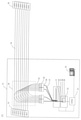
本開示の光ファイバスイッチを適用した光ファイバの監視・測定システムを図7に示す。図7において、11はV溝基板、12はマルチコア光ファイバ、14はマルチコアヘッド光ファイバ、20はシングルコア光ファイバ、21は第1のファンアウト、22はV溝基板、24は第1のシングルコアヘッド光ファイバ、25はシングルコア光ファイバ、26は第2のファンアウト、28は光カプラ、29はマルチ光ファイバコネクタ、51は通信設備ビル、52は操作端末、53はOTM、54はテープ光ファイバ、55はOLT、56はONUである。
通信設備ビル51内のOLT(Optical Line Terminal)55とユーザ側のONU(Optical Network Unit)56の間を光ファイバで接続している。光ファイバとして、ここでは、テープ光ファイバ54を例示している。これらの光ファイバを通信設備ビルからOTM(Optical Testing Module)53で監視・測定する。
OTM53はOTDR(Optical Time Domain Refrectometer)、光ファイバの心線対照用光源等の光測定器及びこれらを制御するコントローラで構成されている。テープ光ファイバ54を監視・測定する試験光や心線対照光の入出力のために、光カプラ28がテープ光ファイバ54に挿入されている。作業者が操作端末52から、監視・測定したい光ファイバを選ぶと、本開示の光ファイバスイッチは、OTM53からの第1のシングルコアヘッド光ファイバ24と光カプラ28からのシングルコア光ファイバ25とを接続する。
図7に示す光ファイバスイッチにおいて、第2のファンアウト26が複数のシングルコア光ファイバ25をN個のコアを有するマルチコア光ファイバ12に変換する。マルチコア接続回路(不図示)が、V溝基板11上の複数のマルチコア光ファイバ12の中から1本のマルチコア光ファイバを選択して、マルチコアヘッド光ファイバ14と接続する。第1のファンアウト21が、マルチコアヘッド光ファイバ14をN本のシングルコア光ファイバ20に変換する。第1のシングルコア接続回路(不図示)が、V溝基板22上の複数のシングルコア光ファイバ20の中から1本のシングルコア光ファイバを選択して、第1のシングルコアヘッド光ファイバ24と接続する。マルチコア接続回路及び第1のシングルコア接続回路は、どちらが先に動作してもよく、同時に動作してもよい。
このような構成と動作により、複数のシングルコア光ファイバ25の中から、任意のシングルコア光ファイバを第1のシングルコアヘッド光ファイバ24に接続することができる。
第2のファンアウト26を光カプラ28の近くに配置すると、光カプラ28と光ファイバスイッチとの間をマルチコア光ファイバで接続できるため、光ファイバの本数を削減でき、光ファイバの収容性の向上に寄与する。
(実施形態2)
本開示の光ファイバスイッチは、V溝基板上に、N個(Nは2以上の正整数)のコアを有するマルチコア光ファイバを複数本並べた第1の光ファイバアレイと、1本のシングルコア光ファイバを用いた第2のシングルコアヘッド光ファイバと、第1の光ファイバアレイの複数本のマルチコア光ファイバの中から1本のマルチコア光ファイバを選択し、選択した1本のマルチコア光ファイバの一端の1個のコアに第2のシングルコアヘッド光ファイバの一端のコアを接続する第2のシングルコア接続回路と、を備える。
本開示の光ファイバスイッチは、V溝基板上に、N個(Nは2以上の正整数)のコアを有するマルチコア光ファイバを複数本並べた第1の光ファイバアレイと、1本のシングルコア光ファイバを用いた第2のシングルコアヘッド光ファイバと、第1の光ファイバアレイの複数本のマルチコア光ファイバの中から1本のマルチコア光ファイバを選択し、選択した1本のマルチコア光ファイバの一端の1個のコアに第2のシングルコアヘッド光ファイバの一端のコアを接続する第2のシングルコア接続回路と、を備える。
このような構成とすることにより、本開示の光ファイバスイッチは、N個のコアを有する複数本のマルチコア光ファイバの中から、任意のマルチコア光ファイバの任意のコアを選択することができる。
本開示の光ファイバスイッチの具体的な構成を図8で説明する。図8において、11はV溝基板、12はマルチコア光ファイバ、13は第1の光ファイバアレイ、34は第2のシングルコアヘッド光ファイバ、35は第2のシングルコア接続回路、36はマルチコア光ファイバ12又は第2のシングルコアヘッド光ファイバ34のコアである。
本開示の光ファイバスイッチは、V溝基板11上に、N個(Nは2以上の正整数)のコアを有するマルチコア光ファイバ12を複数本並べた第1の光ファイバアレイ13と、1本のシングルコア光ファイバを用いた第2のシングルコアヘッド光ファイバ34と、第1の光ファイバアレイ13の複数本のマルチコア光ファイバ12の中から1本のマルチコア光ファイバを選択し、選択した1本のマルチコア光ファイバの一端の1個のコアに第2のシングルコアヘッド光ファイバ34の一端のコアを接続する第2のシングルコア接続回路35と、を備える。
図8に示すように、マルチコア光ファイバ12は、N個のコアが中心から所定距離の同心円状に配置され、第2のシングルコアヘッド光ファイバ34は、1個のコアが中心から同じ所定距離の位置に配置されている。マルチコア光ファイバ12と第2のシングルコアヘッド光ファイバ34との間は、反射を抑制するため、屈折率整合材を充填することが好ましい。
第2のシングルコア接続回路35は、ボールねじやモータ等でX軸及びY軸方向に、第2のシングルコアヘッド光ファイバ34を移動して、第2のシングルコアヘッド光ファイバ34の一端を、第1の光ファイバアレイ13の複数本のマルチコア光ファイバ12の中から1本のマルチコア光ファイバの一端に接続する。X軸方向は、マルチコア光ファイバ12の長軸に対して垂直な面内で、第1の光ファイバアレイ13の配列方向である。Y軸方向は、マルチコア光ファイバ12の長軸に対して垂直な面内で、第1の光ファイバアレイ13の配列方向に直角な方向である。マルチコア光ファイバ12と第2のシングルコアヘッド光ファイバ34は、外径が同じであることが望ましい。
第2のシングルコア接続回路35は、さらに、第2のシングルコアヘッド光ファイバ34を回転させて、選択した1本のマルチコア光ファイバ12の一端の1個のコアに第2のシングルコアヘッド光ファイバ34の一端のコアを接続する。マルチコア光ファイバ12と第2のシングルコアヘッド光ファイバ34は、それぞれの長軸が一致するように、第2のシングルコアヘッド光ファイバ34を回転させることが望ましい。
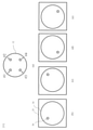
第2のシングルコア接続回路35の回転の様子を図9に示す。図9において、34は第2のシングルコアヘッド光ファイバ、35は第2のシングルコア接続回路である。第2のシングルコア接続回路35は、第2のシングルコアヘッド光ファイバ34をその長軸を中心に回転させて、マルチコア光ファイバ12の一端のN個のコアのうちの1個のコアに第2のシングルコアヘッド光ファイバ34の一端のコアを接続する。
第2のシングルコア接続回路35の、第2のシングルコアヘッド光ファイバ34の長軸に対して垂直な断面図を図10に示す。図10において、34は第2のシングルコアヘッド光ファイバ、35は第2のシングルコア接続回路、36はコアである。第2のシングルコア接続回路35は、コア36を第2のシングルコアヘッド光ファイバ34の長軸を中心に回転させる。
第2のシングルコアヘッド光ファイバ34を回転させて、マルチコア光ファイバ12の一端の1個のコアに、第2のシングルコアヘッド光ファイバ34の一端のコアを接続する状況を図11に示す。図11において、(a)はマルチコア光ファイバ12の一端の端面、(b)、(c)、(d)及び(e)は第2のシングルコアヘッド光ファイバ34の一端を(a)と同じ方向から見た端面である。マルチコア光ファイバ12の#1のコアに接続するには、第2のシングルコアヘッド光ファイバ34を(b)の位置に回転させる。マルチコア光ファイバ12の#2のコアに接続するには、第2のシングルコアヘッド光ファイバ34を(c)の位置に回転させる。マルチコア光ファイバ12の#3のコアに接続するには、第2のシングルコアヘッド光ファイバ34を(d)の位置に回転させる。マルチコア光ファイバ12の#4のコアに接続するには、第2のシングルコアヘッド光ファイバ34を(e)の位置に回転させる。
このような構成とすることにより、本開示の光ファイバスイッチは、N個のコアを有する複数本のマルチコア光ファイバの中から、任意のマルチコア光ファイバの任意のコアを選択して接続することができる。
本開示の光ファイバスイッチは、4コアのマルチコア光ファイバを利用するため、8000心規模であっても、V溝基板11の溝数及び第1の光ファイバアレイ13のアレイ数は、関連技術の光ファイバスイッチの4分の1の2000となる。V溝基板の溝数が少なくなると、光ファイバスイッチは小型化でき、さらに、製造性、コスト、運搬性に優れる。また、V溝基板の幅が狭くなると、マルチコアヘッド光ファイバのX軸方向の移動距離が短くなり、光ファイバスイッチの替え時に光ファイバスイッチのアクセス時間が短くなる。
本開示の光ファイバスイッチでは、マルチコア光ファイバ12のコア数を4としたが、コア数をNとすると、V溝基板11の溝数及び第1の光ファイバアレイ13のアレイ数はN分の1となる。
以上説明したように、N個のコアを有するマルチコア光ファイバを利用することによって、小型化した光ファイバスイッチを提供することができる。
本開示の光ファイバスイッチは、第1の光ファイバアレイ13からの複数本のマルチコア光ファイバ12のそれぞれの他端に、マルチコア光ファイバ12のN個のコアをN本のシングルコア光ファイバに変換する第2のファンアウト26をさらに備えてもよい。第2のファンアウト26の構成については、実施形態1と同様である。
第2のファンアウト26をさらに備える構成とすることにより、複数本のシングルコア光ファイバの中から1本のシングルコア光ファイバに接続する光ファイバスイッチを小型化することができる。
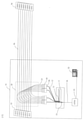
本開示の光ファイバスイッチを適用した光ファイバの監視・測定システムを図12に示す。図12において、11はV溝基板、12はマルチコア光ファイバ、13は第1の光ファイバアレイ、25はシングルコア光ファイバ、26は第2のファンアウト、28は光カプラ、29はマルチ光ファイバコネクタ、34は第2のシングルコアヘッド光ファイバ、35は第2のシングルコア接続回路、51は通信設備ビル、52は操作端末、53はOTM、54はテープ光ファイバ、55はOLT、56はONUである。
通信設備ビル51内のOLT(Optical Line Terminal)55とユーザ側のONU(Optical Network Unit)56の間を光ファイバで接続している。光ファイバとして、ここでは、テープ光ファイバ54を例示している。これらの光ファイバを通信設備ビルからOTM(Optical Testing Module)53で監視・測定する。
OTM53はOTDR(Optical Time Domain Refrectometer)、光ファイバの心線対照用光源等の光測定器及びこれらを制御するコントローラで構成されている。テープ光ファイバ54を監視・測定する試験光や心線対照光の入出力のために、光カプラ28がテープ光ファイバ54に挿入されている。作業者が操作端末52から、監視・測定したい光ファイバを選ぶと、本開示の光ファイバスイッチは、OTM53からの第1のシングルコアヘッド光ファイバ24と光カプラ28からのシングルコア光ファイバ25とを接続する。
図7に示す光ファイバスイッチにおいて、第2のファンアウト26が複数のシングルコア光ファイバ25をN個のコアを有するマルチコア光ファイバ12に変換する。第2のシングルコア接続回路35が、V溝基板11上の複数のマルチコア光ファイバ12の中から1本のマルチコア光ファイバを選択して、選択した1本のマルチコア光ファイバ12の1個のコアに第2のシングルコアヘッド光ファイバ34の一端のコアを接続する。
このような構成と動作により、複数のシングルコア光ファイバ25の中から、任意のシングルコア光ファイバを第2のシングルコアヘッド光ファイバ34に接続することができる。
第2のファンアウト26を光カプラ28の近くに配置すると、光カプラ28と光ファイバスイッチとの間をマルチコア光ファイバで接続できるため、光ファイバの本数を削減でき、光ファイバの収容性の向上に寄与する。
本開示は情報通信産業に適用することができる。
11:V溝基板
12:マルチコア光ファイバ
13:第1の光ファイバアレイ
14:マルチコアヘッド光ファイバ
16:マルチコア光ファイバのコア
20:シングルコア光ファイバ
21:第1のファンアウト
22:V溝基板
23:第2の光ファイバアレイ
24:第1のシングルコアヘッド光ファイバ
25:シングルコア光ファイバ
26:第2のファンアウト
27:シングルコア光ファイバ
28:光カプラ
29:マルチ光ファイバコネクタ
34:第2のシングルコアヘッド光ファイバ
35:第2のシングルコア接続回路
36:コア
51:通信設備ビル
52:操作端末
53:OTM
54:テープ光ファイバ
55:OLT
56:ONU
71:V溝基板
72:テープ光ファイバ
73:光ファイバアレイ
74:ヘッド光ファイバ
78:光カプラ
80:光スイッチ
91:通信設備ビル
92:操作端末
93:OTM
94:テープ光ファイバ
95:OLT
96:ONU
12:マルチコア光ファイバ
13:第1の光ファイバアレイ
14:マルチコアヘッド光ファイバ
16:マルチコア光ファイバのコア
20:シングルコア光ファイバ
21:第1のファンアウト
22:V溝基板
23:第2の光ファイバアレイ
24:第1のシングルコアヘッド光ファイバ
25:シングルコア光ファイバ
26:第2のファンアウト
27:シングルコア光ファイバ
28:光カプラ
29:マルチ光ファイバコネクタ
34:第2のシングルコアヘッド光ファイバ
35:第2のシングルコア接続回路
36:コア
51:通信設備ビル
52:操作端末
53:OTM
54:テープ光ファイバ
55:OLT
56:ONU
71:V溝基板
72:テープ光ファイバ
73:光ファイバアレイ
74:ヘッド光ファイバ
78:光カプラ
80:光スイッチ
91:通信設備ビル
92:操作端末
93:OTM
94:テープ光ファイバ
95:OLT
96:ONU
Claims (5)
- V溝基板上に、N個(Nは2以上の正整数)のコアを有するマルチコア光ファイバを複数本並べた第1の光ファイバアレイと、
N個のコアを有するマルチコア光ファイバを用いたマルチコアヘッド光ファイバと、
前記第1の光ファイバアレイの複数本の前記マルチコア光ファイバの中から1本のマルチコア光ファイバを選択し、選択した前記1本のマルチコア光ファイバの一端のN個のコアに前記マルチコアヘッド光ファイバの一端のN個のコアをそれぞれ接続するマルチコア接続回路と、
を備えることを特徴とする光ファイバスイッチ。 - 前記マルチコアヘッド光ファイバの他端のN個のコアをN本のシングルコア光ファイバに変換する第1のファンアウトと、
V溝基板上に、前記第1のファンアウトからのN本のシングルコア光ファイバを並べた第2の光ファイバアレイと、
1本のシングルコア光ファイバを用いた第1のシングルコアヘッド光ファイバと、
前記第2の光ファイバアレイのN本の前記シングルコア光ファイバの中から1本のシングルコア光ファイバを選択し、選択した1本のシングルコア光ファイバの一端のコアに前記第1のシングルコアヘッド光ファイバの一端のコアをそれぞれ接続する第1のシングルコア接続回路と、
をさらに備えることを特徴とする請求項1に記載の光ファイバスイッチ。 - V溝基板上に、N個(Nは2以上の正整数)のコアを有するマルチコア光ファイバを複数本並べた第1の光ファイバアレイと、
1本のシングルコア光ファイバを用いた第2のシングルコアヘッド光ファイバと、
前記第1の光ファイバアレイの複数本の前記マルチコア光ファイバの中から1本のマルチコア光ファイバを選択し、選択した前記1本のマルチコア光ファイバの一端の1個のコアに前記第2のシングルコアヘッド光ファイバの一端のコアを接続する第2のシングルコア接続回路と、
を備えることを特徴とする光ファイバスイッチ。 - 前記マルチコア光ファイバは、N個のコアが中心から所定距離の同心円状に配置され、
前記第2のシングルコアヘッド光ファイバは、1個のコアが中心から前記所定距離の位置に配置され、
前記第2のシングルコア接続回路は、前記第2のシングルコアヘッド光ファイバをその長軸を中心に回転させて、選択した前記1本のマルチコア光ファイバの一端の1個のコアに前記第2のシングルコアヘッド光ファイバの一端のコアを接続する
ことを特徴とする請求項3に記載の光ファイバスイッチ。 - 前記第1の光ファイバアレイからの複数本の前記マルチコア光ファイバのそれぞれの他端に、前記マルチコア光ファイバのN個のコアをN本のシングルコア光ファイバに変換する第2のファンアウト
をさらに備えることを特徴とする請求項1から4のいずれかに記載の光ファイバスイッチ。
Priority Applications (1)
| Application Number | Priority Date | Filing Date | Title |
|---|---|---|---|
| PCT/JP2020/027302 WO2022013931A1 (ja) | 2020-07-13 | 2020-07-13 | 光ファイバスイッチ |
Applications Claiming Priority (1)
| Application Number | Priority Date | Filing Date | Title |
|---|---|---|---|
| PCT/JP2020/027302 WO2022013931A1 (ja) | 2020-07-13 | 2020-07-13 | 光ファイバスイッチ |
Publications (1)
| Publication Number | Publication Date |
|---|---|
| WO2022013931A1 true WO2022013931A1 (ja) | 2022-01-20 |
Family
ID=79555335
Family Applications (1)
| Application Number | Title | Priority Date | Filing Date |
|---|---|---|---|
| PCT/JP2020/027302 Ceased WO2022013931A1 (ja) | 2020-07-13 | 2020-07-13 | 光ファイバスイッチ |
Country Status (1)
| Country | Link |
|---|---|
| WO (1) | WO2022013931A1 (ja) |
Citations (6)
| Publication number | Priority date | Publication date | Assignee | Title |
|---|---|---|---|---|
| JPH0282212A (ja) * | 1988-09-20 | 1990-03-22 | Fujitsu Ltd | 光スイッチ |
| JPH09211347A (ja) * | 1996-02-05 | 1997-08-15 | Fujikura Ltd | 光ファイバスイッチ |
| JP2001174725A (ja) * | 1999-12-20 | 2001-06-29 | Nippon Telegr & Teleph Corp <Ntt> | メカニカル光スイッチ |
| CN104503031A (zh) * | 2015-01-08 | 2015-04-08 | 武汉正光恒远科技有限公司 | 准直器及包含该准直器的多光路输入对多光路输出的装置 |
| JP2018173535A (ja) * | 2017-03-31 | 2018-11-08 | 国立研究開発法人情報通信研究機構 | 高速マルチコア一括光スイッチシステム |
| JP2019113597A (ja) * | 2017-12-21 | 2019-07-11 | 日本電信電話株式会社 | 光接続構造 |
-
2020
- 2020-07-13 WO PCT/JP2020/027302 patent/WO2022013931A1/ja not_active Ceased
Patent Citations (6)
| Publication number | Priority date | Publication date | Assignee | Title |
|---|---|---|---|---|
| JPH0282212A (ja) * | 1988-09-20 | 1990-03-22 | Fujitsu Ltd | 光スイッチ |
| JPH09211347A (ja) * | 1996-02-05 | 1997-08-15 | Fujikura Ltd | 光ファイバスイッチ |
| JP2001174725A (ja) * | 1999-12-20 | 2001-06-29 | Nippon Telegr & Teleph Corp <Ntt> | メカニカル光スイッチ |
| CN104503031A (zh) * | 2015-01-08 | 2015-04-08 | 武汉正光恒远科技有限公司 | 准直器及包含该准直器的多光路输入对多光路输出的装置 |
| JP2018173535A (ja) * | 2017-03-31 | 2018-11-08 | 国立研究開発法人情報通信研究機構 | 高速マルチコア一括光スイッチシステム |
| JP2019113597A (ja) * | 2017-12-21 | 2019-07-11 | 日本電信電話株式会社 | 光接続構造 |
Similar Documents
| Publication | Publication Date | Title |
|---|---|---|
| Tomlinson | Applications of GRIN-rod lenses in optical fiber communication systems | |
| US5588077A (en) | In-line, two-pass, fiber optic rotary joint | |
| US4360248A (en) | Multiport optical communication system and optical star structure therefor | |
| CN104932061B (zh) | 光纤连接器 | |
| CN203630394U (zh) | 1×n 多通道mems 光开关结构 | |
| Hayashi et al. | Multi-core fibers for data center applications | |
| US5757994A (en) | Three-part optical coupler | |
| US20210381907A1 (en) | Planar optical waveguide device, and temperature measurement system | |
| US4842355A (en) | Multichannel optical rotary joint for well logging usage | |
| US12487479B2 (en) | Integrated optical circulator | |
| EP3887792B1 (en) | Large core apparatus for measuring optical power in multifiber cables | |
| CN202771038U (zh) | 一种m×n多通道mems光开关 | |
| KR20020021085A (ko) | 광섬유의 특성 측정 장치 | |
| US11668878B2 (en) | Fiber-optic switches using multicore optical fibers | |
| Kikuchi et al. | Low insertion loss and high return loss fiber bundle fan-in/fan-out for four-core multi-core fiber | |
| JP7476986B2 (ja) | 光クロスコネクト装置 | |
| Asada et al. | Next generation multi-fiber ferrule using 165 micron pitch optical fiber | |
| JP7525053B2 (ja) | 多心無反射終端部および光線路試験方法 | |
| Nakajima et al. | How can we consider multi‐core fibre standard? | |
| CN219657915U (zh) | 分光装置及分光组件 | |
| JP7524952B2 (ja) | 光スイッチ | |
| JP6507085B2 (ja) | 光ファイバテープ心線モニタ用受光装置、光ファイバテープ心線モニタ方法、及び光回線モニタ方法 | |
| Fukai et al. | Multi-Fiber Cylindrical Ferrule for Remote Rotary Optical Fiber Switching | |
| CN110966925A (zh) | 一种光纤位置检测系统 | |
| Nomoto et al. | SC-type multi-core optical-fiber connectors using a pressurization spring |
Legal Events
| Date | Code | Title | Description |
|---|---|---|---|
| 121 | Ep: the epo has been informed by wipo that ep was designated in this application |
Ref document number: 20945218 Country of ref document: EP Kind code of ref document: A1 |
|
| NENP | Non-entry into the national phase |
Ref country code: DE |
|
| 122 | Ep: pct application non-entry in european phase |
Ref document number: 20945218 Country of ref document: EP Kind code of ref document: A1 |
|
| NENP | Non-entry into the national phase |
Ref country code: JP |