WO2022010183A1 - 사용후 핵연료봉의 초음파 검사 방법 및 핵연료 집합체 - Google Patents
사용후 핵연료봉의 초음파 검사 방법 및 핵연료 집합체 Download PDFInfo
- Publication number
- WO2022010183A1 WO2022010183A1 PCT/KR2021/008384 KR2021008384W WO2022010183A1 WO 2022010183 A1 WO2022010183 A1 WO 2022010183A1 KR 2021008384 W KR2021008384 W KR 2021008384W WO 2022010183 A1 WO2022010183 A1 WO 2022010183A1
- Authority
- WO
- WIPO (PCT)
- Prior art keywords
- fuel
- nuclear fuel
- spent
- ultrasonic
- rod
- Prior art date
- Legal status (The legal status is an assumption and is not a legal conclusion. Google has not performed a legal analysis and makes no representation as to the accuracy of the status listed.)
- Ceased
Links
Images





Classifications
-
- G—PHYSICS
- G21—NUCLEAR PHYSICS; NUCLEAR ENGINEERING
- G21C—NUCLEAR REACTORS
- G21C17/00—Monitoring; Testing ; Maintaining
- G21C17/06—Devices or arrangements for monitoring or testing fuel or fuel elements outside the reactor core, e.g. for burn-up, for contamination
-
- G—PHYSICS
- G01—MEASURING; TESTING
- G01N—INVESTIGATING OR ANALYSING MATERIALS BY DETERMINING THEIR CHEMICAL OR PHYSICAL PROPERTIES
- G01N29/00—Investigating or analysing materials by the use of ultrasonic, sonic or infrasonic waves; Visualisation of the interior of objects by transmitting ultrasonic or sonic waves through the object
- G01N29/04—Analysing solids
-
- G—PHYSICS
- G21—NUCLEAR PHYSICS; NUCLEAR ENGINEERING
- G21C—NUCLEAR REACTORS
- G21C17/00—Monitoring; Testing ; Maintaining
-
- G—PHYSICS
- G21—NUCLEAR PHYSICS; NUCLEAR ENGINEERING
- G21C—NUCLEAR REACTORS
- G21C17/00—Monitoring; Testing ; Maintaining
- G21C17/002—Detection of leaks
-
- G—PHYSICS
- G01—MEASURING; TESTING
- G01N—INVESTIGATING OR ANALYSING MATERIALS BY DETERMINING THEIR CHEMICAL OR PHYSICAL PROPERTIES
- G01N2291/00—Indexing codes associated with group G01N29/00
- G01N2291/02—Indexing codes associated with the analysed material
- G01N2291/023—Solids
-
- Y—GENERAL TAGGING OF NEW TECHNOLOGICAL DEVELOPMENTS; GENERAL TAGGING OF CROSS-SECTIONAL TECHNOLOGIES SPANNING OVER SEVERAL SECTIONS OF THE IPC; TECHNICAL SUBJECTS COVERED BY FORMER USPC CROSS-REFERENCE ART COLLECTIONS [XRACs] AND DIGESTS
- Y02—TECHNOLOGIES OR APPLICATIONS FOR MITIGATION OR ADAPTATION AGAINST CLIMATE CHANGE
- Y02E—REDUCTION OF GREENHOUSE GAS [GHG] EMISSIONS, RELATED TO ENERGY GENERATION, TRANSMISSION OR DISTRIBUTION
- Y02E30/00—Energy generation of nuclear origin
- Y02E30/30—Nuclear fission reactors
Definitions
- the present disclosure relates to a method for ultrasonic inspection of spent nuclear fuel rods and a nuclear fuel assembly.
- the ultrasonic inspection method of spent nuclear fuel rods is a method of determining whether the spent nuclear fuel rods included in the nuclear fuel assembly located in the water are defective using ultrasonic waves.
- the spent fuel rods contained in the nuclear fuel assembly located in the water are inspected for defects using the ultrasonic inspection method of the spent fuel rods. are figuring out
- the conventional ultrasonic inspection method of spent nuclear fuel rods uniformly transmits ultrasonic waves to a certain area where the fuel pellets of the spent nuclear fuel rods are located, without considering the expansion due to the uranium burnout of the fuel pellets located inside the spent nuclear fuel rods. and receives ultrasonic waves from a certain area to determine whether the spent fuel rods are defective.
- An object of the present invention is to provide an ultrasonic inspection method for spent fuel rods with improved reliability of ultrasonic inspection for spent fuel rods.
- the bulge of the control rod guide tube does not overlap the inspection area of the spent nuclear fuel rod.
- One side includes a fuel pellet, a lower shaft blanket positioned below the fuel pellet and having a lower U-235 concentration than the fuel pellet, and a cladding pipe sealing the fuel pellet and the lower shaft blanket with air interposed therebetween
- the ultrasonic wave corresponding to a side surface of a nuclear fuel assembly including a control rod guide tube adjacent to the spent fuel rod and the spent nuclear fuel rod and including a plurality of bulges protruding from the surface
- Positioning a transducer inserting the ultrasonic transducer between the control rod guide tube and a portion of the inspection area of the cladding that overlaps the lower shaft blanket and does not overlap the fuel pellets; injecting ultrasonic waves into the part, and receiving the ultrasonic waves emitted from other parts of the inspection area of the cladding to determine whether the spent fuel rod is defective, wherein the plurality of bulges are Provided is an ultrasonic inspection method of a spent fuel rod that does not overlap the inspection area.
- the inspection area may have a length from a first point spaced 19.28 mm upwardly from the lower end of the spent nuclear fuel rod to a second point spaced 152.4 mm upwardly.
- the U-235 concentration of the lower shaft blanket may be 1.5% to 2.5%, and the U-235 concentration of the fuel pellets may be 4% to 5%.
- the cladding may include zirconium, and the fuel pellets and the lower shaft blanket may include uranium.
- the nuclear fuel assembly may be located underwater.
- the inspection area of the cladding may overlap only the lower shaft blanket.
- one side is a fuel pellet, a lower shaft blanket located below the fuel pellet and having a lower U-235 concentration than the fuel pellet, and a cladding pipe for sealing the fuel pellet and the lower shaft blanket with air interposed therebetween a plurality of nuclear fuel rods including a plurality of fuel rods, and a plurality of control rod guide tubes positioned between the plurality of fuel rods and including a plurality of bulges protruding from a surface, wherein the plurality of bulges overlap the lower shaft blanket. and provides a nuclear fuel assembly that does not overlap the inspection area of the cladding that does not overlap the fuel pellets.
- an ultrasonic testing method for spent fuel rods with improved reliability of ultrasonic testing for spent fuel rods.
- a nuclear fuel assembly in which the bulges of the control rod guide tube do not overlap the inspection area of the spent fuel rod is provided in consideration of the bulge interference between the spent fuel rod and the neighboring control rod guide tube when performing the ultrasonic inspection method of the spent nuclear fuel rod do.
- FIG. 1 is a flowchart illustrating an ultrasonic inspection method of a spent nuclear fuel rod according to an embodiment.
- FIG. 2 is a view showing a nuclear fuel assembly and a spent nuclear fuel rod included therein.
- FIG. 3 is a view for explaining an inspection area of the spent nuclear fuel rod shown in FIG. 2 .
- FIG. 4 is a view illustrating a portion of a control rod guide tube included in a nuclear fuel assembly.
- FIG. 5 is a diagram illustrating insertion of an ultrasonic transducer between a fuel rod and a control rod guide tube after a nuclear fuel assembly has been used.
- FIG. 6 is a graph showing the uranium burn-up according to the overall position of the spent nuclear fuel rod burned three times.
- FIG. 7 is a graph showing a change in the volume of fuel pellets according to the uranium burnout.
- FIG. 8 is a diagram illustrating reflection and transmission of ultrasonic waves at an interface between two materials according to a difference in specific acoustic impedance between the two materials.
- FIG. 10 is a cross-sectional view showing the incidence, reflection, and emission of ultrasonic waves in each of a healthy nuclear fuel rod, a defective nuclear fuel rod, and a high-burnability nuclear fuel rod.
- a pressurized light-water reactor type nuclear power plant uses light water as a coolant and a moderator, and the fuel pellets contained in the nuclear fuel rods can be used by concentrating uranium 235 (U-235) to about 2% to 5% as a nuclear fuel.
- U-235 concentrating uranium 235
- a pressurized light-water reactor type nuclear power plant has a facility related to the reactor system that sends heat generated by nuclear fission in a nuclear reactor to a steam generator for heat exchange, and the steam generated from the steam generator turns a turbine, then reduces it to water through a condenser, and then It can be divided into facilities related to the turbine and generator systems that are circulated to the steam generator.
- the coolant which is the heat transfer medium of the nuclear reactor system
- the equipment constituting the system includes a pressurizer that adjusts the pressure to maintain a constant enthalpy, and a coolant pump that circulates the coolant between the reactor and the steam generator.
- the system in which the steam generated from the steam generator turns the turbine to generate electricity from the generator connected to the turbine shaft may be the same as the principle of a general thermal power plant.
- a pressurized light water reactor (PWR) nuclear power plant as a nuclear facility will be described as an example, but it is not limited thereto, and the spent nuclear fuel rod is used in a boiling light water reactor (BWR) nuclear power plant. It may be a spent nuclear fuel rod.
- PWR pressurized light water reactor
- BWR boiling light water reactor
- FIG. 1 is a flowchart illustrating an ultrasonic inspection method of a spent nuclear fuel rod according to an embodiment.
- 2 is a view showing a nuclear fuel assembly and a spent nuclear fuel rod included therein.
- FIG. 3 is a view for explaining an inspection area of the spent nuclear fuel rod shown in FIG. 2 .
- 4 is a view illustrating a portion of a control rod guide tube included in a nuclear fuel assembly.
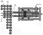
- FIG. 5 is a diagram illustrating insertion of an ultrasonic transducer between a fuel rod and a control rod guide tube after a nuclear fuel assembly has been used.
- the ultrasonic probe 10 is positioned corresponding to the side surface of the nuclear fuel assembly 1000 ( S100 ).
- a nuclear fuel assembly 1000 including a spent fuel rod 100 and a control rod guide tube 200 adjacent to the spent nuclear fuel rod 100 and including a plurality of bulges 210 protruding from the surface In correspondence with the ultrasonic transducer 10 is positioned.
- the ultrasonic probe 10 is inserted between the control rod guide tube 200 and a portion of the inspection area IS of the cladding tube 170 of the nuclear fuel rod 100 after use of the nuclear fuel assembly 1000 ( S200 ).
- An ultrasonic transducer between a portion of the inspection area IS of the cladding tube 170 overlapping the lower shaft blanket 120 of the spent nuclear fuel rod 100 and not overlapping the fuel pellet 110 and the control rod guide tube 200 . (10) is inserted.
- ultrasonic waves are incident on a portion of the inspection area IS of the cladding tube 170 of the spent nuclear fuel rod 100 ( S300 ).
- Ultrasound is incident on a portion of the inspection area IS of the cladding tube 170 overlapping the lower shaft blanket 120 of the spent nuclear fuel rod 100 and not overlapping the fuel pellet 110 .
- the spent nuclear fuel rods 100 used in nuclear facilities such as a pressurized light water reactor (PWR) nuclear power plant are mounted on the nuclear fuel assembly 1000 of the nuclear facility, and are installed in the underwater (underwater) inside the nuclear facility. ) is located in the nuclear fuel assembly 1000 of the nuclear facility.
- PWR pressurized light water reactor
- the ultrasonic wave is transmitted to and received from the inspection region IS of the spent fuel rod 100 .
- the ultrasonic inspection method of the spent nuclear fuel rod may be performed with the spent nuclear fuel rod 100 mounted on the nuclear fuel assembly 1000, but is not limited thereto.
- the inspection area IS of the spent nuclear fuel rod 100 is a second point spaced 152.4 mm upward from the first point S1 spaced 19.28 mm upward from the bottom of the spent nuclear fuel rod 100 upwards ( It may have a length up to S2), but is not limited thereto.
- the spent nuclear fuel rod 100 is a fuel pellet (Enriched Fuel Pellet) 110, a lower axial blanket (Axial Blanket) 120, an upper axial blanket (Axial Blanket) 130, a plenum ( Plenum 140 , a Bottom End Plug 150 , a Top End Plug 160 , and a Cladding Tube 170 .
- the fuel pellets 110 , the lower shaft blanket 120 , and the upper shaft blanket 130 contain uranium.
- the fuel pellet 110 is located in the central portion in the axial direction from the lower end to the upper end of the spent nuclear fuel rod 100 .
- There are a plurality of fuel pellets 110 and the plurality of fuel pellets 110 are stacked in the axial direction of the spent nuclear fuel rod 100 .
- the U-235 enrichment degree which is the uranium 235 enrichment degree of the fuel pellet 110, is 4% to 5%.
- the U-235 concentration of the fuel pellets 110 may be 4.5%.
- the lower shaft blanket 120 is located at a lower portion in the axial direction from the lower end to the upper end of the spent nuclear fuel rod 100 .
- the lower shaft blanket 120 is located below the fuel pellet 110 .
- the lower shaft blanket 120 has a lower U-235 concentration than the fuel pellets 110 .
- the U-235 concentration of the lower shaft blanket 120 is 1.5% to 2.5%.
- the U-235 concentration of the lower shaft blanket 120 may be 2%.
- the upper shaft blanket 130 is located at an upper portion in the axial direction from the lower end to the upper end of the spent nuclear fuel rod 100 .
- the upper shaft blanket 130 is located above the fuel pellets 110 .
- the upper shaft blanket 130 has a lower U-235 concentration than the fuel pellets 110 .
- the U-235 concentration of the upper shaft blanket 130 is 1.5% to 2.5%.
- the U-235 concentration of the upper shaft blanket 130 may be 2%.
- the plenum 140 is positioned between the upper shaft blanket 130 and the upper end plug 160 .
- a spring may be positioned inside the plenum 140, but is not limited thereto.
- the lower end plug 150 is located at the lower end of the spent nuclear fuel rod 100 .
- the upper end plug 160 is located at the top of the spent nuclear fuel rod 100 .
- the cladding tube 170 seals the fuel pellet 110 , the lower shaft blanket 120 , and the upper shaft blanket 130 with air interposed therebetween.
- the cladding 170 includes zirconium.
- the air inside the cladding 170 may include a filling gas including an inert gas such as helium (He), but is not limited thereto.
- a filling gas including an inert gas such as helium (He), but is not limited thereto.
- the ultrasonic wave is transmitted to and received from the inspection region IS of the spent fuel rod 100 .
- the inspection area IS of the spent nuclear fuel rod 100 overlaps with the lower shaft blanket 120 positioned inside the cladding tube 170 of the spent nuclear fuel rod 100 .
- the inspection area IS of the spent nuclear fuel rod 100 does not overlap the fuel pellet 110 .
- the inspection area IS of the spent nuclear fuel rod 100 overlaps only the lower shaft blanket 120 .
- the control rod guide tube 200 included in the nuclear fuel assembly 1000 is adjacent to the plurality of spent nuclear fuel rods 100 included in the nuclear fuel assembly 1000 .
- the control rods are inserted into the nuclear fuel assembly 1000 through the inside of the control rod guide tube 200 .
- the control rod guide tube 200 includes a plurality of bulges 210 protruding from the surface.
- the bulges 210 of the control rod guide tube 200 may be formed by a bulging phenomenon that occurs during operation of a nuclear power plant, or may be formed on the surface of the control rod guide tube 200 at the time of initial design, but is not limited thereto. .
- the bulges 210 of the control rod guide tube 200 do not overlap the inspection area IS of the cladding tube 170 of the spent nuclear fuel rod 100 in the horizontal direction of the nuclear fuel assembly 1000 . That is, the bulges 210 of the control rod guide tube 200 do not overlap the lower shaft blanket 120 of the spent nuclear fuel rod 100 in the horizontal direction.
- the first grid of the nuclear fuel assembly 1000 is adjusted downward, and the bulge 210 overlaps the inspection region IS.
- 210 may be adjusted upward and downward from the inspection area IS, but is not limited thereto.
- the nuclear fuel assembly 1000 is located below the fuel pellet 110 and the fuel pellet 110 before being used as the spent nuclear fuel rod 100, and the lower shaft blanket having a lower U-235 concentration than the fuel pellet 110 ( 120), and a plurality of nuclear fuel rods including a cladding tube 170 sealing the fuel pellet 110 and the lower shaft blanket 120 with air interposed therebetween, and located between the plurality of nuclear fuel rods and protruding from the surface
- a plurality of control rod guide tubes 200 including a plurality of bulges 210 are included.
- the plurality of bulges 210 of the plurality of control rod guide tubes 200 overlap the lower shaft blanket 120 and do not overlap the fuel pellet 110 , and do not overlap the inspection area IS of the cladding tube. That is, the plurality of bulges 210 of the control rod guide tube 200 do not overlap the lower shaft blanket 120 of the spent nuclear fuel rod 100 disposed adjacent to each other in the horizontal direction in the nuclear fuel assembly 1000 in the horizontal direction. .
- the bulges 210 of the control rod guide tube 200 of the nuclear fuel assembly 1000 do not overlap the inspection area IS of the cladding tube 170 of the spent nuclear fuel rod 100, so that the spent nuclear fuel rod is ultrasonically inspected.
- the bulge 210 protrudes from the surface of the control rod guide tube 200 . not interfered by
- the nuclear fuel assembly 1000 in which the bulge interference of the control rod guide tube 200 is prevented in the ultrasonic inspection method of the spent nuclear fuel rod is provided.
- the ultrasonic transducer 10 is positioned corresponding to the side surface of the nuclear fuel assembly 1000 , and a portion of the inspection area of the cladding tube of the nuclear fuel rod 100 after use of the nuclear fuel assembly 1000 and the control rod guide tube The ultrasonic transducer 10 is inserted between the two, and the ultrasonic wave is incident on a part of the inspection area of the cladding tube of the spent nuclear fuel rod 100 .
- An ultrasonic wave is incident on a portion from the first point S1 to the second point S2.
- the conventional ultrasonic inspection method of the spent nuclear fuel rod is uniformly applied to a portion of the third point S3, which is the existing inspection position of the cladding tube 170 overlapping the fuel pellet 110 of the spent nuclear fuel rod 100. Ultrasound was applied.
- the third point S3 may be spaced 215.7 mm upward from the lower end of the spent nuclear fuel rod 100 , but is not limited thereto.
- the cladding tube 170 is damaged and moisture is located inside the cladding tube 170, so after use It is determined that a defect has occurred in the nuclear fuel rod 100 .
- the cladding tube 170 maintains a healthy state so that air is located inside the cladding tube 170 Therefore, it is determined that no defects have occurred in the spent nuclear fuel rod 100 .
- the other part of the third point S3 which is the existing inspection position of the cladding tube 170 overlapping the fuel pellet 110 of the spent nuclear fuel rod 100, uniformly It was determined whether the spent nuclear fuel rod 100 was defective by receiving the emitted ultrasonic waves.
- the inventors of the present invention using the conventional ultrasonic inspection method of the spent nuclear fuel rod, uniformly the third point (S3), which is the existing inspection position of the cladding tube 170 overlapping the fuel pellet 110 of the spent nuclear fuel rod 100 ), and receiving the ultrasonic waves emitted from the other part of the third point S3, which is the existing inspection position, to determine whether the spent fuel rod 100 is defective, the defect does not occur. It was confirmed that there are cases in which the size of the ultrasonic wave emitted from the spent nuclear fuel rod 100 does not exceed the gate, which is a set size level.
- This phenomenon is related to the expansion and density decrease as the fuel pellets 110 of high concentration according to the uranium burn rate are burned inside the nuclear reactor, which will be described in detail with reference to FIGS. 6 to 10 .
- FIG. 6 is a graph showing the uranium burn-up according to the overall position of the spent nuclear fuel rod burned three times.
- the x-axis of FIG. 6 represents the distance from the lower end of the spent nuclear fuel rod, and the y-axis represents the uranium burnout.
- the existing inspection location overlapping the fuel pellets is an area overlapping with the U-235 enrichment area of 4.5% or more, and the existing inspection location is 40,000MWD/MTU (40GWd/ tU) or more overlaps with the high burnout position.
- the ultrasonic inspection method of a spent nuclear fuel rod is an inspection method in consideration of the effect of a phenomenon occurring due to combustion of fuel pellets on an ultrasonic signal.
- PCI physical and chemical interaction between the cladding pipe and the fuel pellet
- HBS high burn-up structure
- FIG. 7 is a graph showing a change in the volume of fuel pellets according to the uranium burnout.
- the x-axis represents the uranium burnout
- the y-axis represents the volume change of fuel pellets.
- the fuel pellet expands (swelling) while gaseous fission products and defects are generated inside the fuel pellet. At this time, the fuel pellets expand and come into physical and chemical contact with the cladding. As the burn-up of the fuel pellets increases, the expansion of the fuel pellets increases.
- HBS high burn up structure
- FIG 8 is a diagram illustrating reflection and transmission of ultrasonic waves at an interface between two materials according to a difference in specific acoustic impedance between the two materials.
- Z 1 , Z 2 Each means the intrinsic acoustic impedance of the material included in each material, ⁇ 1 , Each of ⁇ 2 means the density of each material, and V 1 , V 2 each means the speed of ultrasonic waves in each material.
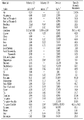
- FIG. 9 is a table showing the specific acoustic impedance according to the material included in the material.
- the specific acoustic impedances of zirconium in the cladding and uranium in fuel pellets are 29.8 and 63.0, respectively, so there is not much difference between the two materials. Thereby, the intrinsic acoustic impedance difference between the fuel pellets and the cladding is further reduced.
- FIG. 10 is a cross-sectional view illustrating transmission, reflection, and reception of ultrasonic waves in each of a healthy nuclear fuel rod, a defective nuclear fuel rod, and a high burnup fuel rod.
- A) of FIG. 10 is a sound nuclear fuel rod
- B) is a defective nuclear fuel rod
- C) is a high-burnability nuclear fuel rod.
- Ultrasonic testing of spent fuel rods is performed in an underwater environment.
- the ultrasonic waves initially incident from the ultrasonic transmitter to the cladding tube of the spent fuel rods reach the inner interface of the cladding, and reflect the ultrasonic waves due to the large specific acoustic impedance difference between the air and the cladding at the inner interface.
- the reflected ultrasonic waves reach the outer interface of the cladding, part of the ultrasonic waves are reflected due to the small specific acoustic impedance difference between the water outside the cladding and the cladding, and the rest is leaked and absorbed into the water, resulting in ultrasonic energy loss (reducing sound pressure).
- This process is repeated a plurality of times until the ultrasonic wave reaches the receiver, but since the ultrasonic wave received by the receiver exceeds the gate, which is the set ultrasonic intensity level, it is determined as a healthy nuclear fuel rod.
- ultrasonic energy loss occurs only at the outer boundary surface of the cladding, but in the case of a defective nuclear fuel rod, water, which is water, also exists inside the cladding, so that ultrasonic energy is lost inside and outside the cladding. Due to this occurrence, the ultrasonic amplitude received by the receiver does not exceed the gate, which is the set ultrasonic amplitude level, so that it is determined as a defective nuclear fuel rod.
- the fuel pellet expands to physically and chemically contact the cladding tube, and the contact portion of the fuel pellet is The low density reduces the difference in specific acoustic impedance at the interface between the cladding and fuel pellets, resulting in ultrasonic energy loss inside and outside the cladding. Due to this, since the ultrasonic amplitude received by the receiver does not exceed the gate that is the set ultrasonic amplitude level, an error occurs in that a high-burn fuel rod is determined as a defective nuclear fuel rod rather than a defective nuclear fuel rod in which water has flowed into the cladding tube.
- the ultrasonic inspection method of a spent nuclear fuel rod in consideration of the expansion and density decrease due to the uranium burn-up of the fuel pellet, it does not overlap with the fuel pellet and at the same time provides a low U-235 enrichment level compared to the fuel pellet.
- the branch transmits ultrasonic waves to a part of the inspection area of the cladding tube of the spent nuclear fuel rod overlapping the lower shaft blanket and receives ultrasonic waves from the other part of the inspection area, regardless of whether the fuel pellets having a high degree of combustion expand or decrease in density. It is clearly determined whether the spent nuclear fuel rod is defective.
- the reliability of ultrasonic inspection of spent fuel rods is improved by accurately determining sound and defective nuclear fuel rods without the error of determining that high-burn fuel rods, rather than defective nuclear fuel rods with water flowing into the interior of the cladding, are defective fuel rods.
- a method for ultrasonic testing of spent nuclear fuel rods is provided.
- the ultrasonic inspection reliability of the spent nuclear fuel rod is improved by performing defect determination in consideration of the influence of the intrinsic acoustic impedance of the high-burn fuel pellets.
- the ultrasonic inspection method of a spent fuel rod suppresses the occurrence of fuel rod repair cost, process delay, and system and worker radiation exposure dose increase that would occur due to the determination of a nuclear fuel rod defect by an unclear ultrasonic signal, It contributes to the reduction of system and worker radiation exposure dose while improving the operating efficiency of nuclear power plants by reducing the overall cost.
- the spent nuclear fuel rod ultrasonic inspection method contributes to reducing the cost of dry storage of the spent nuclear fuel rods by clearly performing the presence or absence of defects in the spent nuclear fuel rods for each unit.
- the ultrasonic probe responds to the inspection area in the ultrasonic inspection method of the spent fuel rod after use When inserted between the fuel rod and the control rod guide tube, it is not interfered with by the bulge protruding from the surface of the control rod guide tube. That is, there is provided a nuclear fuel assembly in which the bulge interference of the control rod guide tube is prevented in the ultrasonic inspection method of the spent nuclear fuel rod.
Landscapes
- Physics & Mathematics (AREA)
- Engineering & Computer Science (AREA)
- High Energy & Nuclear Physics (AREA)
- General Engineering & Computer Science (AREA)
- Plasma & Fusion (AREA)
- Chemical & Material Sciences (AREA)
- Biochemistry (AREA)
- General Health & Medical Sciences (AREA)
- General Physics & Mathematics (AREA)
- Immunology (AREA)
- Pathology (AREA)
- Analytical Chemistry (AREA)
- Life Sciences & Earth Sciences (AREA)
- Health & Medical Sciences (AREA)
- Acoustics & Sound (AREA)
- Monitoring And Testing Of Nuclear Reactors (AREA)
- Investigating Or Analyzing Materials By The Use Of Ultrasonic Waves (AREA)
Abstract
사용후 핵연료봉의 초음파 검사 방법(ULTRASONIC INSPECTION METHOD OF SPENT NUCLEAR FUEL ROD)은 사용후 핵연료봉 및 제어봉 가이드 튜브를 포함하는 핵연료 집합체의 측면에 대응하여 초음파 탐촉자를 위치시키는 단계, 상기 사용후 핵연료봉의 하부 축 블랭킷과 중첩하고 연료 펠렛과 비중첩하는 피복관의 검사 영역의 일 부분과 상기 제어봉 가이드 튜브 사이에 상기 초음파 탐촉자를 삽입시키는 단계, 상기 피복관의 상기 검사 영역의 상기 일부분에 초음파를 입사시키는 단계, 및 상기 피복관의 상기 검사 영역의 타 부분에서 출사되는 상기 초음파를 수신하여 상기 사용후 핵연료봉의 결함 여부를 판정하는 단계를 포함하며, 상기 제어봉 가이드 튜브의 복수의 벌지들은 상기 피복관의 상기 검사 영역과 비중첩한다.
Description
본 기재는 사용후 핵연료봉의 초음파 검사 방법 및 핵연료 집합체에 관한 것이다.
일반적으로, 사용후 핵연료봉의 초음파 검사 방법은 초음파를 이용해 수중(underwater)에 위치하는 핵연료 집합체에 포함된 사용후 핵연료봉의 결함 여부를 파악하는 방법이다.
현재, 원자력 시설의 원자로에서 사용된 사용후 핵연료봉을 건식 저장 시설로 운반하기 전에, 사용후 핵연료봉의 초음파 검사 방법을 이용해 수중(underwater)에 위치하는 핵연료 집합체에 포함된 사용후 핵연료봉의 결함 여부를 파악하고 있다.
종래의 사용후 핵연료봉의 초음파 검사 방법은, 사용후 핵연료봉의 내부에 위치하는 연료 펠렛의 우라늄 연소도에 따른 팽창을 고려하지 않고, 일률적으로 사용후 핵연료봉의 연료 펠렛이 위치하는 일정 영역에 초음파를 송신하고 일정 영역으로부터 초음파를 수신하여 사용후 핵연료봉의 결함 여부를 파악한다.
일 실시예는, 연료 펠렛의 우라늄 연소도에 따른 팽창과 연료 펠렛의 밀도 감소를 고려하여, 연료 펠렛과 비중첩하는 사용후 핵연료봉의 검사 영역에 초음파를 송신하고 검사 영역으로부터 초음파를 수신함으로써, 사용후 핵연료봉에 대한 초음파 검사 신뢰도가 향상된 사용후 핵연료봉의 초음파 검사 방법을 제공하고자 한다.
또한, 사용후 핵연료봉의 초음파 검사 방법 수행 시 사용후 핵연료봉과 이웃하는 제어봉 가이드 튜브의 벌지(bulge) 간섭을 고려하여, 제어봉 가이드 튜브의 벌지들이 사용후 핵연료봉의 검사 영역과 비중첩하는 핵연료 집합체를 제공하고자 한다.
일 측면은 연료 펠렛, 상기 연료 펠렛의 하측에 위치하며 상기 연료 펠렛 대비 낮은 U-235 농축도를 가지는 하부 축 블랭킷, 및 공기를 사이에 두고 상기 연료 펠렛과 상기 하부 축 블랭킷을 밀봉하는 피복관을 포함하는 사용후 핵연료봉의 초음파 검사 방법에 있어서, 상기 사용후 핵연료봉 및 상기 사용후 핵연료봉과 이웃하며 표면에 돌출된 복수의 벌지(bulge)들을 포함하는 제어봉 가이드 튜브를 포함하는 핵연료 집합체의 측면에 대응하여 초음파 탐촉자를 위치시키는 단계, 상기 하부 축 블랭킷과 중첩하고 상기 연료 펠렛과 비중첩하는 상기 피복관의 검사 영역의 일 부분과 상기 제어봉 가이드 튜브 사이에 상기 초음파 탐촉자를 삽입시키는 단계, 상기 피복관의 상기 검사 영역의 상기 일부분에 초음파를 입사시키는 단계, 및 상기 피복관의 상기 검사 영역의 타 부분에서 출사되는 상기 초음파를 수신하여 상기 사용후 핵연료봉의 결함 여부를 판정하는 단계를 포함하며, 상기 복수의 벌지들은 상기 피복관의 상기 검사 영역과 비중첩하는 사용후 핵연료봉의 초음파 검사 방법을 제공한다.
상기 검사 영역은 상기 사용후 핵연료봉의 하단으로부터 상측으로 19.28mm 이격된 제1 지점으로부터 상기 상측으로 152.4mm 이격된 제2 지점까지의 길이를 가질 수 있다.
상기 하부 축 블랭킷의 U-235 농축도는 1.5% 내지 2.5%이며, 상기 연료 펠렛의 U-235 농축도는 4% 내지 5%일 수 있다.
상기 피복관은 지르코늄을 포함하며, 상기 연료 펠렛 및 상기 하부 축 블랭킷은 우라늄을 포함할 수 있다.
상기 핵연료 집합체는 수중(underwater)에 위치할 수 있다.
상기 피복관의 검사 영역은 상기 하부 축 블랭킷에만 중첩할 수 있다.
또한, 일 측면은 연료 펠렛, 상기 연료 펠렛의 하측에 위치하며 상기 연료 펠렛 대비 낮은 U-235 농축도를 가지는 하부 축 블랭킷, 및 공기를 사이에 두고 상기 연료 펠렛과 상기 하부 축 블랭킷을 밀봉하는 피복관을 포함하는 복수의 핵연료봉들, 및 상기 복수의 핵연료봉들 사이에 위치하며, 표면에 돌출된 복수의 벌지들을 포함하는 복수의 제어봉 가이드 튜브들을 포함하며, 상기 복수의 벌지들은 상기 하부 축 블랭킷과 중첩하고 상기 연료 펠렛과 비중첩하는 상기 피복관의 검사 영역과 비중첩하는 핵연료 집합체를 제공한다.
일 실시예에 따르면, 연료 펠렛의 우라늄 연소도에 따른 팽창과 연료 펠렛의 밀도 감소를 고려하여, 연료 펠렛과 비중첩하는 사용후 핵연료봉의 검사 영역에 초음파를 송신하고 검사 영역으로부터 초음파를 수신함으로써, 사용후 핵연료봉에 대한 초음파 검사 신뢰도가 향상된 사용후 핵연료봉의 초음파 검사 방법이 제공된다.
또한, 사용후 핵연료봉의 초음파 검사 방법 수행 시 사용후 핵연료봉과 이웃하는 제어봉 가이드 튜브의 벌지(bulge) 간섭을 고려하여, 제어봉 가이드 튜브의 벌지들이 사용후 핵연료봉의 검사 영역과 비중첩하는 핵연료 집합체가 제공된다.
도 1은 일 실시예에 따른 사용후 핵연료봉의 초음파 검사 방법을 나타낸 순서도이다.
도 2는 핵연료 집합체 및 이에 포함된 사용후 핵연료봉을 나타낸 도면이다.
도 3은 도 2에 도시된 사용후 핵연료봉의 검사 영역을 설명하기 위한 도면이다.
도 4는 핵연료 집합체에 포함된 제어봉 가이드 튜브의 일 부분을 나타낸 도면이다.
도 5는 핵연료 집합체의 사용후 핵연료봉과 제어봉 가이드 튜브 사이에 초음파 탐촉자를 삽입시키는 것을 나타낸 도면이다.
도 6은 3회 연소된 사용후 핵연료봉의 전체 위치에 따른 우라늄 연소도를 나타낸 그래프이다.
도 7은 우라늄 연소도에 따른 연료 펠렛의 부피 변화를 나타낸 그래프이다.
도 8은 두 물질간의 고유 음향 임피던스(Specific Acoustic Impedance) 차이에 따른 두 물질간의 계면에서의 초음파의 반사 및 투과를 나타낸 도면이다.
도 9는 재료에 따른 고유 음향 임피던스를 나타낸 표이다.
도 10은 건전 핵연료봉, 결함 핵연료봉, 고연소도 핵연료봉 각각에서 초음파의 입사, 반사, 출사를 나타낸 횡단면도이다.
이하, 첨부한 도면을 참고로 하여 본 발명의 실시예에 대하여 본 발명이 속하는 기술 분야에서 통상의 지식을 가진 자가 용이하게 실시할 수 있도록 상세히 설명한다. 본 발명은 여러 가지 상이한 형태로 구현될 수 있으며 여기에서 설명하는 실시예에 한정되지 않는다.
또한, 명세서 전체에서, 어떤 부분이 어떤 구성요소를 "포함" 한다고 할 때, 이는 특별히 반대되는 기재가 없는 한 다른 구성요소를 제외하는 것이 아니라 다른 구성요소를 더 포함할 수 있는 것을 의미한다.
이하, 도 1 내지 도 10을 참조하여 일 실시예에 따른 사용후 핵연료봉의 초음파 검사 방법을 설명한다.
가압 경수로형 원자력 발전소는 냉각재와 감속재로 경수를 사용하고, 핵연료봉 내부에 포함된 연료 펠렛은 핵연료로서 우라늄 235(U-235)를 약 2% 내지 5%로 농축하여 사용할 수 있다. 가압 경수로형 원자력 발전소는 원자로 내에서 핵분열로 발생되는 열을 증기 발생기로 보내 열 교환시키는 원자로 계통에 관련되는 시설과, 증기 발생기에서 발생된 증기로 터빈을 돌린 후 복수기를 거쳐 물로 환원시킨 다음, 다시 증기 발생기로 순환되는 터빈 및 발전기 계통에 관련되는 시설로 구분될 수 있다.
일반적으로 원자로 계통의 열전달 매체인 냉각재(경수)는 원자로에서 약 320℃까지 가열되며, 비등하지 않도록 약 157 기압으로 가압된다. 계통을 구성하는 기기로는 일정한 엔탈피를 유지하기 위하여 압력을 조정하는 가압기, 원자로와 증기발생기 사이에 냉각재를 순환시켜 주는 냉각재 펌프가 있다. 증기 발생기에서 발생된 증기가 터빈을 돌려 터빈 축에 연결된 발전기에서 전력을 생산하는 계통은 일반 화력 발전소의 원리와 동일할 수 있다.
이하에서는, 원자력 시설로서 가압 경수로형(PWR) 원자력 발전소에서 사용된 사용후 핵연료봉의 초음파 검사 방법을 일례로 설명하나, 이에 한정되지 않지 않고 사용후 핵연료봉은 비등 경수로형(BWR) 원자력 발전소에서 사용된 사용후 핵연료봉일 수 있다.
도 1은 일 실시예에 따른 사용후 핵연료봉의 초음파 검사 방법을 나타낸 순서도이다. 도 2는 핵연료 집합체 및 이에 포함된 사용후 핵연료봉을 나타낸 도면이다. 도 3은 도 2에 도시된 사용후 핵연료봉의 검사 영역을 설명하기 위한 도면이다. 도 4는 핵연료 집합체에 포함된 제어봉 가이드 튜브의 일 부분을 나타낸 도면이다. 도 5는 핵연료 집합체의 사용후 핵연료봉과 제어봉 가이드 튜브 사이에 초음파 탐촉자를 삽입시키는 것을 나타낸 도면이다.
우선, 도 1 내지 도 5를 참조하면, 핵연료 집합체(1000)의 측면에 대응하여 초음파 탐촉자(10)를 위치시킨다(S100).
사용후 핵연료봉(100) 및 사용후 핵연료봉(100)과 이웃하며 표면에 돌출된 복수의 벌지(bulge)(210)들을 포함하는 제어봉 가이드 튜브(200)를 포함하는 핵연료 집합체(1000)의 측면에 대응하여 초음파 탐촉자(10)를 위치시킨다.
다음, 핵연료 집합체(1000)의 사용후 핵연료봉(100)의 피복관(170)의 검사 영역(IS)의 일 부분과 제어봉 가이드 튜브(200) 사이에 초음파 탐촉자(10)를 삽입한다(S200).
사용후 핵연료봉(100)의 하부 축 블랭킷(120)과 중첩하고 연료 펠렛(110)과 비중첩하는 피복관(170)의 검사 영역(IS)의 일 부분과 제어봉 가이드 튜브(200) 사이에 초음파 탐촉자(10)를 삽입시킨다.
다음, 사용후 핵연료봉(100)의 피복관(170)의 검사 영역(IS)의 일 부분에 초음파를 입사시킨다(S300).
사용후 핵연료봉(100)의 하부 축 블랭킷(120)과 중첩하고 연료 펠렛(110)과 비중첩하는 피복관(170)의 검사 영역(IS)의 일 부분에 초음파를 입사시킨다.
구체적으로, 도 2를 참조하면, 가압 경수로형(PWR) 원자력 발전소 등의 원자력 시설에서 사용된 사용후 핵연료봉(100)들은 원자력 시설의 핵연료 집합체(1000)에 장착되어 원자력 시설 내부의 수중(underwater)에 위치한다.
일 실시예에 따른 사용후 핵연료봉의 초음파 검사 방법은 초음파를 사용후 핵연료봉(100)의 검사 영역(IS)에 송신하고 검사 영역(IS)으로부터 수신한다.
사용후 핵연료봉의 초음파 검사 방법은 사용후 핵연료봉(100)이 핵연료 집합체(1000)에 장착된 상태로 수행될 수 있으나, 이에 한정되지는 않는다.
일례로, 사용후 핵연료봉(100)의 검사 영역(IS)은 사용후 핵연료봉(100)의 하단으로부터 상측으로 19.28mm 이격된 제1 지점(S1)으로부터 상측으로 152.4mm 이격된 제2 지점(S2)까지의 길이를 가질 수 있으나, 이에 한정되지는 않는다.
도 3을 참조하면, 사용후 핵연료봉(100)은 연료 펠렛(Enriched Fuel Pellet)(110), 하부 축 블랭킷(Axial Blanket)(120), 상부 축 블랭킷(Axial Blanket)(130), 플리넘(Plenum)(140), 하부 엔드 플러그(Bottom End Plug)(150), 상부 엔드 플러그(Top End Plug)(160), 피복관(Cladding Tube)(170)을 포함한다.
연료 펠렛(110), 하부 축 블랭킷(120), 상부 축 블랭킷(130)은 우라늄을 포함한다.
연료 펠렛(110)은 사용후 핵연료봉(100)의 하단으로부터 상단까지의 축 방향에서 중앙 부분에 위치한다. 연료 펠렛(110)은 복수이며, 복수의 연료 펠렛(110)들은 사용후 핵연료봉(100)의 축 방향으로 적층되어 있다. 연료 펠렛(110)의 우라늄 235 농축도인 U-235 농축도는 4% 내지 5%이다. 일례로, 연료 펠렛(110)의 U-235 농축도는 4.5%일 수 있다.
하부 축 블랭킷(120)은 사용후 핵연료봉(100)의 하단으로부터 상단까지의 축 방향에서 하부에 위치한다. 하부 축 블랭킷(120)은 연료 펠렛(110)의 하측에 위치한다. 하부 축 블랭킷(120)은 연료 펠렛(110) 대비 낮은 U-235 농축도를 가진다. 하부 축 블랭킷(120)의 U-235 농축도는 1.5% 내지 2.5%이다. 일례로, 하부 축 블랭킷(120)의 U-235 농축도는 2%일 수 있다.
상부 축 블랭킷(130)은 사용후 핵연료봉(100)의 하단으로부터 상단까지의 축 방향에서 상부에 위치한다. 상부 축 블랭킷(130)은 연료 펠렛(110)의 상측에 위치한다. 상부 축 블랭킷(130)은 연료 펠렛(110) 대비 낮은 U-235 농축도를 가진다. 상부 축 블랭킷(130)의 U-235 농축도는 1.5% 내지 2.5%이다. 일례로, 상부 축 블랭킷(130)의 U-235 농축도는 2%일 수 있다.
플리넘(140)은 상부 축 블랭킷(130)과 상부 엔드 플러그(160) 사이에 위치한다. 플리넘(140)의 내부에는 스프링(spring)이 위치할 수 있으나, 이에 한정되지는 않는다.
하부 엔드 플러그(150)는 사용후 핵연료봉(100)의 하단에 위치한다.
상부 엔드 플러그(160)는 사용후 핵연료봉(100)의 상단에 위치한다.
피복관(170)은 공기(Air)를 사이에 두고 연료 펠렛(110), 하부 축 블랭킷(120), 상부 축 블랭킷(130)을 밀봉한다. 피복관(170)은 지르코늄을 포함한다.
여기서, 피복관(170) 내부의 공기(Air)는 헬륨(He) 등의 불활성 기체를 포함하는 충전 가스를 포함할 수 있으나, 이에 한정되지는 않는다.
일 실시예에 따른 사용후 핵연료봉의 초음파 검사 방법은 초음파를 사용후 핵연료봉(100)의 검사 영역(IS)에 송신하고 검사 영역(IS)으로부터 수신한다.
사용후 핵연료봉(100)의 검사 영역(IS)은 사용후 핵연료봉(100)의 피복관(170) 내부에 위치하는 하부 축 블랭킷(120)과 중첩한다. 사용후 핵연료봉(100)의 검사 영역(IS)은 연료 펠렛(110)과 비중첩한다.
사용후 핵연료봉(100)의 검사 영역(IS)은 하부 축 블랭킷(120)에만 중첩한다.
도 3 내지 도 5를 참조하면, 핵연료 집합체(1000)에 포함된 제어봉 가이드 튜브(200)는 핵연료 집합체(1000)에 포함된 복수의 사용후 핵연료봉(100)들과 이웃한다. 원전 운영 시 제어봉 가이드 튜브(200)의 내부를 통해 제어봉들이 핵연료 집합체(1000)에 삽입된다. 제어봉 가이드 튜브(200)는 표면에 돌출된 복수의 벌지(bulge)(210)들을 포함한다. 제어봉 가이드 튜브(200)의 벌지(210)들은 원전 운영 중 발생되는 벌징(bulging) 현상에 의해 형성되거나, 또는 최초 설계 시 제어봉 가이드 튜브(200)의 표면에 형성될 수 있으나, 이에 한정되지는 않는다. 제어봉 가이드 튜브(200)의 벌지(210)들은 사용후 핵연료봉(100)의 피복관(170)의 검사 영역(IS)과 핵연료 집합체(1000)의 수평 방향으로 비중첩한다. 즉, 제어봉 가이드 튜브(200)의 벌지(210)들은 사용후 핵연료봉(100)의 하부 축 블랭킷(120)과 수평 방향으로 비중첩한다.
제어봉 가이드 튜브(200)의 벌지(210)들이 검사 영역(IS)과 비중첩되기 위해, 핵연료 집합체(1000)의 첫번째 그리드(1st grid)가 하향 조정되고, 검사 영역(IS)과 중첩하는 벌지(210)들이 검사 영역(IS)으로부터 상향 조정 및 하향 조정될 수 있으나, 이에 한정되지는 않는다.
핵연료 집합체(1000)는 사용후 핵연료봉(100)으로 사용되기 전에 연료 펠렛(110), 연료 펠렛(110)의 하측에 위치하며 연료 펠렛(110) 대비 낮은 U-235 농축도를 가지는 하부 축 블랭킷(120), 및 공기를 사이에 두고 연료 펠렛(110)과 하부 축 블랭킷(120)을 밀봉하는 피복관(170)을 포함하는 복수의 핵연료봉들, 및 복수의 핵연료봉들 사이에 위치하며 표면에 돌출된 복수의 벌지(210)들을 포함하는 복수의 제어봉 가이드 튜브(200)들을 포함한다. 이때, 복수의 제어봉 가이드 튜브(200)들의 복수의 벌지(210)들은 하부 축 블랭킷(120)과 중첩하고 연료 펠렛(110)과 비중첩하여, 피복관의 검사 영역(IS)과 비중첩한다. 즉, 제어봉 가이드 튜브(200)의 복수의 벌지(210)들은 핵연료 집합체(1000)에서 수평 방향으로 이웃하여 배치된 사용후 핵연료봉(100)의 하부 축 블랭킷(120)과 수평 방향으로 비중첩한다.
이와 같이, 핵연료 집합체(1000)의 제어봉 가이드 튜브(200)의 벌지(210)들이 사용후 핵연료봉(100)의 피복관(170)의 검사 영역(IS)과 비중첩함으로써, 사용후 핵연료봉의 초음파 검사 방법 시 초음파 탐촉자(10)가 검사 영역(IS)에 대응하여 사용후 핵연료봉(100)과 제어봉 가이드 튜브(200) 사이로 삽입될 때, 제어봉 가이드 튜브(200)의 표면으로부터 돌출된 벌지(210)에 의해 간섭되지 않는다.
즉, 사용후 핵연료봉의 초음파 검사 방법 시 제어봉 가이드 튜브(200)의 벌지 간섭이 방지되는 핵연료 집합체(1000)가 제공된다.
도 5를 참조하면, 핵연료 집합체(1000)의 측면에 대응하여 초음파 탐촉자(10)를 위치시키고, 핵연료 집합체(1000)의 사용후 핵연료봉(100)의 피복관의 검사 영역의 일 부분과 제어봉 가이드 튜브 사이에 초음파 탐촉자(10)를 삽입시키고, 사용후 핵연료봉(100)의 피복관의 검사 영역의 일 부분에 초음파를 입사시킨다.
도 3을 참조하면, 사용후 핵연료봉(100)의 하단으로부터 상단까지의 축 방향에서 하부 축 블랭킷(120)과 중첩하고 연료 펠렛(110)과 비중첩하는 피복관(170)의 검사 영역(IS)인 제1 지점(S1)으로부터 제2 지점(S2)까지의 일 부분에 초음파를 입사시킨다.
이와 다르게, 종래의 사용후 핵연료봉의 초음파 검사 방법은 일률적으로 사용후 핵연료봉(100)의 연료 펠렛(110)과 중첩하는 피복관(170)의 기존 검사 위치인 제3 지점(S3)의 일 부분에 초음파를 입사시켰다. 일례로, 제3 지점(S3)은 사용후 핵연료봉(100)의 하단으로부터 상측으로 215.7mm 이격될 수 있으나, 이에 한정되지는 않는다.
다음, 피복관(170)의 검사 영역(IS)의 타 부분에서 출사되는 초음파를 수신하여 사용후 핵연료봉(100)의 결함 여부를 판정한다(S400).
구체적으로, 사용후 핵연료봉(100)의 피복관(170)의 검사 영역(IS)의 타 부분에서 출사되는 초음파를 수신하여 초음파의 크기가 설정된 크기 수준인 게이트(Gate)를 넘는지를 확인함으로써, 사용후 핵연료봉(100)의 결함 여부를 판정한다.
피복관(170)의 검사 영역(IS)의 타 부분에서 출사되는 초음파의 크기가 게이트를 넘지 못한 경우, 피복관(170) 등이 파손되어 피복관(170)의 내부에 수분이 위치하는 것이기 때문에, 사용후 핵연료봉(100)에 결함이 발생된 것으로 판정한다.
피복관(170)의 검사 영역(IS)의 타 부분에서 출사되는 초음파의 크기가 게이트를 넘을 경우, 피복관(170) 등이 건전한 상태를 유지하여 피복관(170)의 내부에 공기(Air)가 위치하는 것이기 때문에, 사용후 핵연료봉(100)에 결함이 발생되지 않은 것으로 판정한다.
이와 다르게, 종래의 사용후 핵연료봉의 초음파 검사 방법은 일률적으로 사용후 핵연료봉(100)의 연료 펠렛(110)과 중첩하는 피복관(170)의 기존 검사 위치인 제3 지점(S3)의 타 부분에서 출사되는 초음파를 수신하여 사용후 핵연료봉(100)의 결함 여부를 판정하였다.
본 발명의 발명자들은, 종래의 사용후 핵연료봉의 초음파 검사 방법을 이용해, 일률적으로 사용후 핵연료봉(100)의 연료 펠렛(110)과 중첩하는 피복관(170)의 기존 검사 위치인 제3 지점(S3)의 일 부분에 초음파를 입사시키고, 기존 검사 위치인 제3 지점(S3)의 타 부분에서 출사되는 초음파를 수신하여 사용후 핵연료봉(100)의 결함 여부를 판정할 경우, 결함이 발생되지 않은 사용후 핵연료봉(100)으로부터 출사되는 초음파의 크기가 설정된 크기 수준인 게이트를 넘지 못하는 경우가 있는 것을 확인하였다.
이러한 현상은 우라늄 연소도에 따른 고농축도의 연료 펠렛(110)이 원자로 내부에서 연소됨에 따른 팽창 및 밀도 감소와 관계가 있는 것으로서, 이를 도 6 내지 도 10을 참조하여 구체적으로 설명한다.
도 6은 3회 연소된 사용후 핵연료봉의 전체 위치에 따른 우라늄 연소도를 나타낸 그래프이다. 도 6의 x축은 사용후 핵연료봉의 하단으로부터의 거리를 나타내며, y축은 우라늄 연소도를 나타낸다.
도 6을 참조하면, 연료 펠렛과 중첩하는 기존 검사 위치는 U-235 농축도가 4.5% 이상인 영역과 중첩하는 영역으로서, 기존 검사 위치는 3회 연소된 연료 펠렛의 경우에 40,000MWD/MTU (40GWd/tU) 이상의 고연소도 위치와 중첩한다.
일 실시예에 따른 사용후 핵연료봉의 초음파 검사 방법은 연료 펠렛의 연소로 인해 나타나는 현상이 초음파 신호에 미치는 영향을 고려한 검사 방법으로서, 고연소도를 가지는 연료 펠렛에서 나타나는 연료 펠렛의 팽창(Swelling)으로 인한 연료 펠렛과 피복관 사이의 접촉, 피복관과 연료 펠렛의 물리적 및 화학적 상호작용(PCI), HBS(high burn up structure) 등 고연소도를 가지는 연료 펠렛의 영향으로 인한 초음파 검출 신호가 저하되는 원인을 회피할 수 있는 위치에서, 초음파 검사를 수행하여 사용후 핵연료봉의 결함 여부의 판정의 정확도가 향상되는 방법이다.
도 7은 우라늄 연소도에 따른 연료 펠렛의 부피 변화를 나타낸 그래프이다. 도 7에서 x축은 우라늄 연소도를 나타내며, y축은 연료 펠렛의 부피 변화를 나타낸다.
도 7을 참조하면, 연료 펠렛은 연소가 진행되면 연료 펠렛 내부에서 기체상 핵분열 생성물 및 결함들이 생성되면서 팽창(swelling)한다. 이때, 연료 펠렛은 팽창하여 피복관과 물리 및 화학적으로 접촉하게 된다. 연료 펠렛의 연소도가 높아질수록 연료 펠렛의 팽창은 증가한다.
연료 펠렛이 팽창하면, 연료 펠렛은 전체적으로 밀도가 감소한다. 특히 연료 펠렛의 최외곽에는 높은 핵분열 반응으로 인하여 기공 밀도가 높은 고연소도 구조(HBS, high burn up structure)가 생성됨으로써, 연료 펠렛과 피복관 사이의 접촉 부위 밀도가 크게 저하된다.
도 8은 두 물질간의 고유 음향 임피던스(Specific Acoustic Impedance) 차이에 따른 두 물질간의 계면에서의 초음파의 반사 및 투과를 나타낸 도면이다. 도 8에서 Z1, Z2 각각은 각 물질에 포함된 재료의 고유 음향 임피던스를 의미하며, ρ1, ρ2 각각은 각 물질의 밀도를 의미하며, V1, V2 각각은 각 물질에서의 초음파의 속도를 의미한다.
도 9는 물질에 포함된 재료에 따른 고유 음향 임피던스를 나타낸 표이다.
도 8 및 도 9를 참조하면, 초음파는 두 물질의 계면(interface)에서 고유 음향 임피던스(물질에서 초음파의 속도와 물질의 밀도의 곱) 차이가 크면 두 물질의 계면에서 반사되고, 두 물질의 계면에서 고유 음향 임피던스 차이가 작으면 두 물질의 계면을 투과하게 된다.
우라늄을 포함하는 연료 펠렛과 지르코늄을 포함하는 피복관 사이의 접촉 부위 밀도가 크게 감소하여, 연료 펠렛과 피복관의 고유 음향 임피던스 차이가 작아지면, 피복관으로 입사된 초음파 중 일부는 피복관과 연료 펠렛의 계면에서 반사되지 않고 연료 펠렛 쪽으로 진행함으로써, 피복관으로부터 출사된 초음파의 크기가 작아진다.
피복관의 지르코늄 및 연료 펠렛의 우라늄 각각의 고유 음향 임피던스는 29.8 및 63.0 각각으로 두 물질간의 차이가 크지 않으며, 고연소도 연료 펠렛의 경우 피복관과의 접촉 부위의 밀도 감소로 인해 초음파의 속도도 감소하게 됨으로써, 연료 펠렛과 피복관간의 고유 음향 임피던스 차이는 더 감소한다.
도 10은 건전 핵연료봉, 결함 핵연료봉, 고연소도 핵연료봉 각각에서 초음파의 송신, 반사, 수신을 나타낸 횡단면도이다. 도 10의 (A)는 건전 핵연료봉이며, (B)는 결함 핵연료봉이며, (C)는 고연소도 핵연료봉이다.
사용후 핵연료봉의 초음파 검사 방법은 수중 환경에서 수행된다.
도 10의 (A)를 참조하면, 초음파 송신부에서 사용후 핵연료봉의 피복관으로 최초 입사된 초음파는 피복관 내부 경계면에 도달하고, 내부 경계면에서 공기와 피복관 사이의 큰 고유 음향 임피던스 차이로 인하여 초음파 반사가 이루어진다. 반사된 초음파가 피복관 외부 경계면에 도달하면, 피복관 외부의 물과 피복관 사이의 작은 고유 음향 임피던스 차이로 인해 초음파의 일부가 반사되고 나머지가 물로 누설 및 흡수되어 초음파 에너지 손실이 발생(음압 감소)된다. 초음파가 수신부에 도달할 때까지 이 과정은 복수 회 반복되나, 수신부에 수신된 초음파의 크기가 설정된 초음파 크기 수준인 게이트(Gate)를 넘으므로, 건전 핵연료봉으로 판정한다.
도 10의 (B)를 참조하면, 건전 핵연료봉의 경우 피복관 외부 경계면에서만 물을 만나 초음파 에너지 손실이 발생하나, 결함 핵연료봉의 경우 피복관 내부에도 수분인 물이 존재하여 피복관의 내부 및 외부에서 초음파 에너지 손실이 발생함으로써, 수신부에 수신된 초음파 크기가 설정된 초음파 크기 수준인 게이트를 넘지 못하므로, 결함 핵연료봉으로 판정한다.
도 10의 (C)를 참조하면, 고연소도 핵연료봉의 경우 피복관 내부에 수분인 물이 존재하지 않아도, 연료 펠렛(pellet)이 팽창하여 피복관과 물리 및 화학적으로 접촉하고, 연료 펠렛의 접촉 부위의 밀도가 낮아 피복관과 연료 펠렛 사이의 경계면의 고유 음향 임피던스 차이가 작아짐으로써, 피복관의 내부 및 외부에서 초음파 에너지 손실이 발생한다. 이로 인해, 수신부에 수신된 초음파 크기가 설정된 초음파 크기 수준인 게이트를 넘지 못함으로써, 피복관 내부에 물이 유입된 결함 핵연료봉이 아닌 고연소도 핵연료봉이 결함 핵연료봉으로 판정되는 오류가 발생한다.
이상과 같이, 일 실시예에 따른 사용후 핵연료봉의 초음파 검사 방법은, 연료 펠렛의 우라늄 연소도에 따른 팽창 및 밀도 저하를 고려하여, 연료 펠렛과 비중첩하는 동시에 연료 펠렛 대비 낮은 U-235 농축도를 가지는 하부 축 블랭킷과 중첩하는 사용후 핵연료봉의 피복관의 검사 영역의 일 부분에 초음파를 송신하고 검사 영역의 타 부분으로부터 초음파를 수신함으로써, 고연소도를 가지는 연료 펠렛의 팽창 및 밀도 저하 여부와 상관 없이 사용후 핵연료봉의 결함 여부를 명확히 판정한다.
즉, 피복관 내부에 물이 유입된 결함 핵연료봉이 아닌 고연소도 핵연료봉을 결함 핵연료봉으로 판정하는 오류 없이, 건전 핵연료봉과 결함 핵연료봉을 정확히 판정함으로써, 사용후 핵연료봉에 대한 초음파 검사 신뢰도가 향상된 사용후 핵연료봉의 초음파 검사 방법이 제공된다.
또한, 일 실시예에 따른 사용후 핵연료봉의 초음파 검사 방법은, 고연소 연료 펠렛의 고유 음향 임피던스 영향을 고려한 결함 판별을 수행함으로써, 사용후 핵연료봉에 대한 초음파 검사 신뢰도가 향상된다.
또한, 일 실시예에 따른 사용후 핵연료봉의 초음파 검사 방법은, 불명확한 초음파 신호에 의한 핵연료봉 결함 판정으로 인해 발생될 핵연료봉 수리 비용 발생, 공정 지연, 계통 및 작업자 방사선 피폭 선량 증가를 억제함으로써, 전체적인 비용 감소에 따른 원전 운영 효율을 개선하는 동시에 계통 및 작업자 방사선 피폭 선량 감소에 기여한다.
또한, 일 실시예에 따른 사용후 핵연료봉 초음파 검사 방법은, 사용후 핵연료봉 결함 유무를 단위 별로 명확히 수행함으로써, 사용후 핵연료봉의 건식 저장 비용 감소에 기여한다.
또한, 핵연료 집합체의 제어봉 가이드 튜브의 벌지들이 사용후 핵연료봉의 피복관의 검사 영역과 초음파 탐촉자가 삽입되는 수평 방향으로 비중첩함으로써, 사용후 핵연료봉의 초음파 검사 방법 시 초음파 탐촉자가 검사 영역에 대응하여 사용후 핵연료봉과 제어봉 가이드 튜브 사이로 삽입될 때, 제어봉 가이드 튜브의 표면으로부터 돌출된 벌지에 의해 간섭되지 않는다. 즉, 사용후 핵연료봉의 초음파 검사 방법 시 제어봉 가이드 튜브의 벌지 간섭이 방지되는 핵연료 집합체가 제공된다.
이상에서 본 발명의 실시예에 대하여 상세하게 설명하였지만 본 발명의 권리범위는 이에 한정되는 것은 아니고 다음의 청구범위에서 정의하고 있는 본 발명의 기본 개념을 이용한 당업자의 여러 변형 및 개량 형태 또한 본 발명의 권리범위에 속하는 것이다.
[부호의 설명]
사용후 핵연료봉(100), 연료 펠렛(110), 하부 축 블랭킷(120), 피복관(170), 검사 영역(IS), 제어봉 가이드 튜브(200), 벌지(210)
Claims (7)
- 연료 펠렛, 상기 연료 펠렛의 하측에 위치하며 상기 연료 펠렛 대비 낮은 U-235 농축도를 가지는 하부 축 블랭킷, 및 공기를 사이에 두고 상기 연료 펠렛과 상기 하부 축 블랭킷을 밀봉하는 피복관을 포함하는 사용후 핵연료봉의 초음파 검사 방법에 있어서,상기 사용후 핵연료봉 및 상기 사용후 핵연료봉과 이웃하며 표면에 돌출된 복수의 벌지(bulge)들을 포함하는 제어봉 가이드 튜브를 포함하는 핵연료 집합체의 측면에 대응하여 초음파 탐촉자를 위치시키는 단계;상기 하부 축 블랭킷과 중첩하고 상기 연료 펠렛과 비중첩하는 상기 피복관의 검사 영역의 일 부분과 상기 제어봉 가이드 튜브 사이에 상기 초음파 탐촉자를 삽입시키는 단계;상기 피복관의 상기 검사 영역의 상기 일부분에 초음파를 입사시키는 단계; 및상기 피복관의 상기 검사 영역의 타 부분에서 출사되는 상기 초음파를 수신하여 상기 사용후 핵연료봉의 결함 여부를 판정하는 단계를 포함하며,상기 복수의 벌지들은 상기 피복관의 상기 검사 영역과 비중첩하는 사용후 핵연료봉의 초음파 검사 방법.
- 제1항에서,상기 검사 영역은 상기 사용후 핵연료봉의 하단으로부터 상측으로 19.28mm 이격된 제1 지점으로부터 상기 상측으로 152.4mm 이격된 제2 지점까지의 길이를 가지는 사용후 핵연료봉의 초음파 검사 방법.
- 제1항에서,상기 하부 축 블랭킷의 U-235 농축도는 1.5% 내지 2.5%이며,상기 연료 펠렛의 U-235 농축도는 4% 내지 5%인 사용후 핵연료봉의 초음파 검사 방법.
- 제1항에서,상기 피복관은 지르코늄을 포함하며,상기 연료 펠렛 및 상기 하부 축 블랭킷은 우라늄을 포함하는 사용후 핵연료봉의 초음파 검사 방법.
- 제1항에서,상기 핵연료 집합체는 수중(underwater)에 위치하는 사용후 핵연료봉의 초음파 검사 방법.
- 제1항에서,상기 피복관의 검사 영역은 상기 하부 축 블랭킷에만 중첩하는 사용후 핵연료봉의 초음파 검사 방법.
- 연료 펠렛, 상기 연료 펠렛의 하측에 위치하며 상기 연료 펠렛 대비 낮은 U-235 농축도를 가지는 하부 축 블랭킷, 및 공기를 사이에 두고 상기 연료 펠렛과 상기 하부 축 블랭킷을 밀봉하는 피복관을 포함하는 복수의 핵연료봉들; 및상기 복수의 핵연료봉들 사이에 위치하며, 표면에 돌출된 복수의 벌지들을 포함하는 복수의 제어봉 가이드 튜브들을 포함하며,상기 복수의 벌지들은 상기 하부 축 블랭킷과 중첩하고 상기 연료 펠렛과 비중첩하는 상기 피복관의 검사 영역과 비중첩하는 핵연료 집합체.
Applications Claiming Priority (2)
| Application Number | Priority Date | Filing Date | Title |
|---|---|---|---|
| KR1020200083498A KR102437683B1 (ko) | 2020-07-07 | 2020-07-07 | 사용후 핵연료봉의 초음파 검사 방법 및 핵연료 집합체 |
| KR10-2020-0083498 | 2020-07-07 |
Publications (1)
| Publication Number | Publication Date |
|---|---|
| WO2022010183A1 true WO2022010183A1 (ko) | 2022-01-13 |
Family
ID=79342997
Family Applications (1)
| Application Number | Title | Priority Date | Filing Date |
|---|---|---|---|
| PCT/KR2021/008384 Ceased WO2022010183A1 (ko) | 2020-07-07 | 2021-07-01 | 사용후 핵연료봉의 초음파 검사 방법 및 핵연료 집합체 |
Country Status (2)
| Country | Link |
|---|---|
| KR (1) | KR102437683B1 (ko) |
| WO (1) | WO2022010183A1 (ko) |
Families Citing this family (2)
| Publication number | Priority date | Publication date | Assignee | Title |
|---|---|---|---|---|
| KR20250017769A (ko) | 2023-07-27 | 2025-02-04 | 한전원자력연료 주식회사 | 중수로 사용후핵연료 특성 측정용 매니퓰레이터, 및 이를 사용한 그 시스템 |
| KR102779691B1 (ko) | 2023-07-27 | 2025-03-12 | 한전원자력연료 주식회사 | Lvdt 및 ect를 이용한 핵연료봉 검사모듈, 및 이를 구비한 중수로 사용후 핵연료 특성 측정용 매니퓰레이터 |
Citations (4)
| Publication number | Priority date | Publication date | Assignee | Title |
|---|---|---|---|---|
| JPH06273558A (ja) * | 1993-02-26 | 1994-09-30 | Westinghouse Electric Corp <We> | 燃料棒 |
| KR100270724B1 (ko) * | 1992-03-26 | 2000-11-01 | 로빈 엘. 포이에르바허 | 음향 에너지 주파수 감쇠를 이용하여 파손된 핵연료봉을 탐지하기 위한 방법 및 장치 |
| KR100963061B1 (ko) * | 2008-03-21 | 2010-06-14 | 한국원자력연구원 | 핵연료 손상 감지유닛 및 이를 포함하는 핵연료 손상감지장치 |
| KR20110001173A (ko) * | 2009-06-29 | 2011-01-06 | 한국전력공사 | 핵연료 집합체 검사 장치 |
-
2020
- 2020-07-07 KR KR1020200083498A patent/KR102437683B1/ko active Active
-
2021
- 2021-07-01 WO PCT/KR2021/008384 patent/WO2022010183A1/ko not_active Ceased
Patent Citations (4)
| Publication number | Priority date | Publication date | Assignee | Title |
|---|---|---|---|---|
| KR100270724B1 (ko) * | 1992-03-26 | 2000-11-01 | 로빈 엘. 포이에르바허 | 음향 에너지 주파수 감쇠를 이용하여 파손된 핵연료봉을 탐지하기 위한 방법 및 장치 |
| JPH06273558A (ja) * | 1993-02-26 | 1994-09-30 | Westinghouse Electric Corp <We> | 燃料棒 |
| KR100963061B1 (ko) * | 2008-03-21 | 2010-06-14 | 한국원자력연구원 | 핵연료 손상 감지유닛 및 이를 포함하는 핵연료 손상감지장치 |
| KR20110001173A (ko) * | 2009-06-29 | 2011-01-06 | 한국전력공사 | 핵연료 집합체 검사 장치 |
Non-Patent Citations (1)
| Title |
|---|
| KIM KYUNGGUN, LEE SEOJEONG: "Demonstration Test for Determining Spent Nuclear Fuel Inspection Method for Dry Storage", TRANSACTIONS OF THE KOREAN NUCLEAR SOCIETY AUTUMN MEETING, YEOSU, KOREA, 25 October 2018 (2018-10-25) - 26 October 2018 (2018-10-26), Yeosu, Korea, XP055887002 * |
Also Published As
| Publication number | Publication date |
|---|---|
| KR20220005837A (ko) | 2022-01-14 |
| KR102437683B1 (ko) | 2022-08-26 |
Similar Documents
| Publication | Publication Date | Title |
|---|---|---|
| CA1091339A (en) | Apparatus and method for detecting defective fuel rods | |
| EP2471071B1 (en) | A vented nuclear fission fuel module | |
| US8488734B2 (en) | Nuclear fission reactor, a vented nuclear fission fuel module, methods therefor and a vented nuclear fission fuel module system | |
| WO2022067194A3 (en) | Systems and methods for laser inspection and measurements | |
| KR102437683B1 (ko) | 사용후 핵연료봉의 초음파 검사 방법 및 핵연료 집합체 | |
| US9721677B2 (en) | Nuclear fission reactor, a vented nuclear fission fuel module, methods therefor, and a vented nuclear fission fuel module system | |
| CN114334200A (zh) | 一种用于高温气冷堆运行状态下燃料球完整性的检测系统 | |
| KR102297999B1 (ko) | 사용후 핵연료봉의 초음파 검사 방법 | |
| US8929505B2 (en) | Nuclear fission reactor, vented nuclear fission fuel module, methods therefor and a vented nuclear fission fuel module system | |
| CN204288823U (zh) | 水下抗辐照激光测量设备 | |
| US20110051877A1 (en) | Nuclear fission reactor, a vented nuclear fission fuel module, methods therefor and a vented nuclear fission fuel module system | |
| US20110150167A1 (en) | Nuclear fission reactor, a vented nuclear fission fuel module, methods therefor and a vented nuclear fission fuel module system | |
| GB847636A (en) | Improvements in or relating to nuclear reactor refuelling devices | |
| CN119418978B (zh) | 辐照舱的延长装置及辐照系统 | |
| WO2020167043A1 (ko) | 원자력 시설의 수중 해체 방법 | |
| Appleby | Compilation of data and descriptions for United States and foreign liquid metal fast breeder reactors | |
| Cholvy et al. | PHENIX-The neutronography reactor and its auxialiary circuits-Criticality safety issues | |
| JPH08136691A (ja) | 原子炉炉心内計装装置 | |
| Vinzens et al. | Structural integrity of lmfbrs including leak before break | |
| WO2025154877A1 (ko) | 다중 동시 논리 프로세서를 이용한 원자로 보호계통 | |
| MacEwan | Zirconium Alloys in Service in Nuclear Reactors/Examination of Fuel Channel Components From Pickering NGS “A” Units 1 and 2 | |
| Craig | Failure analysis: tube R20L84, B steam generator, Fort Calhoun | |
| Kapoor et al. | Unusual occurrences in fast breeder test reactor | |
| Gibbs | The influence of inspection requirements on reactor design | |
| Kiryushin et al. | Design of the advanced reactor BN-600M |
Legal Events
| Date | Code | Title | Description |
|---|---|---|---|
| 121 | Ep: the epo has been informed by wipo that ep was designated in this application |
Ref document number: 21837249 Country of ref document: EP Kind code of ref document: A1 |
|
| NENP | Non-entry into the national phase |
Ref country code: DE |
|
| 122 | Ep: pct application non-entry in european phase |
Ref document number: 21837249 Country of ref document: EP Kind code of ref document: A1 |