WO2022009795A1 - 容量制御弁 - Google Patents
容量制御弁 Download PDFInfo
- Publication number
- WO2022009795A1 WO2022009795A1 PCT/JP2021/025135 JP2021025135W WO2022009795A1 WO 2022009795 A1 WO2022009795 A1 WO 2022009795A1 JP 2021025135 W JP2021025135 W JP 2021025135W WO 2022009795 A1 WO2022009795 A1 WO 2022009795A1
- Authority
- WO
- WIPO (PCT)
- Prior art keywords
- valve
- valve body
- main
- control
- port
- Prior art date
- Legal status (The legal status is an assumption and is not a legal conclusion. Google has not performed a legal analysis and makes no representation as to the accuracy of the status listed.)
- Ceased
Links
Images



Classifications
-
- F—MECHANICAL ENGINEERING; LIGHTING; HEATING; WEAPONS; BLASTING
- F04—POSITIVE - DISPLACEMENT MACHINES FOR LIQUIDS; PUMPS FOR LIQUIDS OR ELASTIC FLUIDS
- F04B—POSITIVE-DISPLACEMENT MACHINES FOR LIQUIDS; PUMPS
- F04B27/00—Multi-cylinder pumps specially adapted for elastic fluids and characterised by number or arrangement of cylinders
- F04B27/08—Multi-cylinder pumps specially adapted for elastic fluids and characterised by number or arrangement of cylinders having cylinders coaxial with, or parallel or inclined to, main shaft axis
- F04B27/14—Control
- F04B27/16—Control of pumps with stationary cylinders
- F04B27/18—Control of pumps with stationary cylinders by varying the relative positions of a swash plate and a cylinder block
-
- F—MECHANICAL ENGINEERING; LIGHTING; HEATING; WEAPONS; BLASTING
- F16—ENGINEERING ELEMENTS AND UNITS; GENERAL MEASURES FOR PRODUCING AND MAINTAINING EFFECTIVE FUNCTIONING OF MACHINES OR INSTALLATIONS; THERMAL INSULATION IN GENERAL
- F16K—VALVES; TAPS; COCKS; ACTUATING-FLOATS; DEVICES FOR VENTING OR AERATING
- F16K31/00—Actuating devices; Operating means; Releasing devices
- F16K31/02—Actuating devices; Operating means; Releasing devices electric; magnetic
- F16K31/06—Actuating devices; Operating means; Releasing devices electric; magnetic using a magnet, e.g. diaphragm valves, cutting off by means of a liquid
Definitions
- the present invention relates to a capacity control valve that variably controls the capacity of a working fluid, for example, a capacity control valve that controls the discharge amount of a variable capacity compressor used in an automobile air conditioning system according to pressure.
- Variable-capacity compressors used in air conditioning systems such as automobiles include a rotary shaft that is driven to rotate by an engine, a swash plate that is variably connected to a swash plate with a tilt angle, and a piston for compression that is connected to the swash plate.
- the stroke amount of the piston is changed to control the discharge amount of the fluid.
- the inclination angle of this swash plate is determined by the suction pressure Ps of the suction chamber that sucks the fluid and the discharge pressure Pd of the discharge chamber that discharges the fluid pressurized by the piston by using the capacity control valve that is driven to open and close by electromagnetic force. While utilizing the control pressure Pc of the control chamber accommodating the swash plate, the pressure in the control chamber can be continuously changed by appropriately controlling the pressure.
- the capacity control valve When the capacity variable compressor is continuously driven, the capacity control valve is energized and controlled by a control computer, and the valve body is moved in the axial direction by the electromagnetic force generated by the solenoid, and the discharge port through which the discharge fluid of the discharge pressure Pd passes. Normal control is performed to adjust the control pressure Pc of the control chamber in the variable capacity compressor by opening and closing the main valve provided between the control port and the control port through which the control fluid of the control pressure Pc passes.
- the pressure in the control chamber of the variable capacitance compressor is appropriately controlled, and the stroke amount of the piston is changed by continuously changing the tilt angle of the swash plate with respect to the rotation axis.
- the amount of fluid discharged to the discharge chamber is controlled so that the air conditioning system has the target cooling capacity.
- the main valve in the capacity control valve is closed to reduce the pressure in the control chamber, thereby maximizing the tilt angle of the swash plate.
- an auxiliary communication passage is formed to communicate between the control port and the suction port of the capacity control valve, and the refrigerant in the control chamber of the variable capacity compressor at startup is of the variable capacity type through the control port, the auxiliary communication passage, and the suction port. It is also known that the responsiveness of the variable capacity compressor is improved by discharging the pressure to the suction chamber of the compressor and rapidly reducing the pressure in the control chamber at the time of starting (see Patent Document 1).
- Patent Document 1 Although the fluid discharge function is excellent at the time of starting, the auxiliary communication passage is communicated and the refrigerant flows from the control port to the suction port when the capacity variable compressor is continuously driven. The amount of refrigerant circulation is large, and there is a risk that the operating efficiency of the variable capacity compressor will decrease.
- the present invention has been made by paying attention to such a problem, and an object of the present invention is to provide a capacity control valve having a fluid discharge function at the time of starting and having good operation efficiency.
- the capacitance control valve of the present invention is used.
- a valve housing formed with a discharge port through which the discharge fluid of the discharge pressure passes, a suction port through which the suction fluid of the suction pressure passes, and a control port through which the control fluid of the control pressure passes.
- a capacitance control valve including a main valve body driven by a solenoid, and a main valve provided between the discharge port and the control port and composed of a main valve seat with which the main valve body can contact.
- a communication hole is formed, and the CS valve body is interlocked with the main valve body and slides to the valve housing. The communication hole is between the control port and the suction port according to the slide position of the CS valve body.
- the CS valve has a spool valve structure, and the rate of increase in the opening of the communication hole with respect to the valve body stroke from before the fully opened state to the fully opened state can be increased from the time when the valve starts to open from the fully closed state.
- the solenoid in the control valve is not energized and is not energized, the main valve is fully open and the CS valve is fully closed.
- the rate of increase in the opening of the communication hole from the beginning of opening of the CS valve is small, so that fluid leakage is small and the operation efficiency of the capacity control valve is high.
- the main valve When the variable capacity compressor is started, the main valve is fully closed and the CS valve is fully open, and the control port and the suction port are communicated with each other, so that the liquefied fluid in the control chamber is short in the suction chamber through the communication hole. It is discharged in time. In this way, the capacitance control valve can enhance the responsiveness at the time of starting the variable capacitance compressor.
- the CS valve body may be composed of a separate member that can be separated from the main valve body. According to this, since the main valve body and the CS valve body can independently take the axis, the influence on each other's operation is suppressed, and the opening degree of the main valve and the CS valve can be adjusted with high accuracy. Can be done.
- the main valve body and the CS valve body may be in contact with each other only in the axial direction. According to this, the influence on each other's operation due to the inclination or deviation of the axial center between the main valve body and the CS valve body can be suppressed.
- the CS valve body may be urged in the closing direction by a spring. According to this, since the CS valve body follows the main valve body when the main valve is opened, the communication hole of the CS valve can be reliably closed.
- the communication hole is a hole that penetrates in the radial direction, and the opening shape may be formed from a part of a circle. According to this, the opening degree of the communication hole can be gradually increased according to the valve body stroke.
- the opening shape of the communication hole may be a circle. According to this, it is easy to process and form the communication hole for the CS valve body.
- FIG. 5 is an enlarged cross-sectional view showing a state in which a communication hole is started to open from a fully closed state by a CS valve in an energized state (during normal control) of the capacity control valve of the embodiment.
- FIG. 5 is an enlarged cross-sectional view showing a state in which the main valve is closed and the communication hole is fully opened by the CS valve in the maximum energized state (at the time of starting) of the capacity control valve of the embodiment. It is a figure explaining the opening area of the main valve and CS valve (communication hole) with respect to the stroke position of the main and sub-valve body of an Example. The stroke position on the horizontal axis is shown in the direction in which the main / sub valve body moves when a current is applied to the solenoid (direction from right to left in FIG. 2).
- the capacity control valve according to the embodiment will be described with reference to FIGS. 1 to 6.
- the left and right sides when viewed from the front side of FIG. 2 will be described as the left and right sides of the capacitance control valve.
- the capacity control valve V of the present invention is incorporated in the variable capacity compressor M used in an air conditioning system such as an automobile.
- the capacity control valve V variably controls the pressure of the working fluid (hereinafter, simply referred to as “fluid”) which is a refrigerant in the variable capacity compressor M.
- fluid the working fluid which is a refrigerant in the variable capacity compressor M.
- the capacity control valve V controls the discharge amount of the variable capacity compressor M and adjusts the air conditioning system so as to have a desired cooling capacity.
- variable capacity compressor M As shown in FIG. 1, the variable capacity compressor M has a casing 1 including a discharge chamber 2, a suction chamber 3, a control chamber 4, and a plurality of cylinders 4a.
- the variable capacity compressor M is provided with a communication passage (not shown) that directly communicates the control chamber 4 and the suction chamber 3.
- a fixed orifice for balancing the pressure between the suction chamber 3 and the control chamber 4 is provided in this communication passage.
- variable capacity compressor M includes a rotating shaft 5, a swash plate 6, and a plurality of pistons 7.
- the rotary shaft 5 is rotationally driven by an engine (not shown) installed outside the casing 1.
- the swash plate 6 is slantably connected to the rotating shaft 5 by a hinge mechanism 8 in the control chamber 4.
- the plurality of pistons 7 are connected to the swash plate 6 and reciprocally fitted in each cylinder 4a.
- FIG. 1 omits the illustration of the capacitance control valve V incorporated in the variable capacitance compressor M.
- the capacitance control valve V is incorporated in the variable capacitance compressor M.
- the main valve 50, the sub valve 55, and the CS valve 57 in the capacitance control valve V are controlled to open and close.
- the pressure sensitive body 61 is operated by the suction pressure Ps in the intermediate communication passage 59, so that the pressure sensitive valve 53 is controlled to open and close.
- the fluid flowing into or out of the control chamber 4 is controlled.
- the control pressure Pc in the control chamber 4 is variably controlled.
- the main valve 50 is composed of a main valve body 51 as a main valve body and a main valve seat 10a.
- the main valve seat 10a is formed on the inner peripheral surface of the valve housing 10.
- the main valve 50 opens and closes when the axial left end surface 51a of the main / sub valve body 51 comes into contact with the main valve seat 10a.
- the pressure-sensitive valve 53 is composed of a cap 70 and a pressure-sensitive valve seat 52a.
- the cap 70 is also a member constituting the pressure sensitive body 61.
- the pressure-sensitive valve seat 52a is formed on the left end surface in the axial direction of the pressure-sensitive valve member 52.
- the pressure-sensitive valve 53 opens and closes when the sealing surface 70a formed on the inner diameter side at the right end of the cap 70 in the axial direction is brought into contact with and separated from the pressure-sensitive valve seat 52a.
- the sub-valve 55 is composed of a main sub-valve body 51 and a sub-valve seat 82a.
- the auxiliary valve seat 82a is formed on the open end surface of the fixed iron core 82, that is, the left end surface in the axial direction.
- the auxiliary valve 55 opens and closes when the axial right end surface 51b of the main auxiliary valve body 51 comes into contact with and separates from the auxiliary valve seat 82a.
- the CS valve 57 is composed of a CS valve body 56 and a guide surface 10e.
- the guide surface 10e is formed on the inner peripheral surface of the valve housing 10.
- the capacitance control valve V includes a valve housing 10, a main / sub valve body 51, a pressure sensitive valve member 52, a contact member 54, a CS valve body 56, and a pressure sensitive body 61. It is mainly composed of a solenoid 80 and.
- the valve housing 10 is made of a metal material or a resin material.
- the main / sub valve body 51, the pressure sensitive valve member 52, the contact member 54, and the CS valve body 56 are arranged in the valve housing 10 so as to be reciprocally reciprocating in the axial direction.
- the pressure-sensitive body 61 applies an urging force to the right in the axial direction to the main / sub-valve body 51, the pressure-sensitive valve member 52, and the contact member 54 according to the suction pressure Ps in the intermediate communication passage 59.
- the solenoid 80 is connected to the valve housing 10 and exerts a driving force on the main / sub valve body 51, the pressure sensitive valve member 52, the contact member 54, and the CS valve body 56.
- the solenoid 80 is mainly composed of a casing 81, a fixed iron core 82, a drive rod 83, a movable iron core 84, a coil spring 85, and a coil 86.
- the casing 81 has an opening 81a that opens to the left in the axial direction.
- the fixed iron core 82 is formed in a substantially cylindrical shape, is inserted from the left side in the axial direction with respect to the opening 81a in the casing 81, and is fixed to the inner diameter side of the casing 81.
- the drive rod 83 is reciprocating in the axial direction on the inner diameter side of the fixed iron core 82, and its left end portion in the axial direction is connected and fixed to the right end portion in the main / sub valve body 51 in the axial direction.
- the movable iron core 84 is fixed to the right end portion in the axial direction of the drive rod 83.
- the coil spring 85 is provided between the fixed iron core 82 and the movable iron core 84, and urges the movable iron core 84 to the right in the axial direction.
- the exciting coil 86 is wound around the outside of the fixed iron core 82 via a bobbin.
- a recess 81b recessed to the right in the axial direction is formed on the inner diameter side of the left end portion of the casing 81 in the axial direction.
- the right end portion of the valve housing 10 in the axial direction is inserted and fixed in the casing 81 in a substantially sealed shape with respect to the recess 81b.
- the fixed iron core 82 is formed of a rigid body which is a magnetic material such as iron or silicon steel.
- the fixed iron core 82 includes a cylindrical portion 82b and a flange portion 82d.
- the cylindrical portion 82b is formed with an insertion hole 82c extending in the axial direction through which the drive rod 83 is inserted.
- the flange portion 82d is an annular shape extending in the outer diameter direction from the outer peripheral surface of the left end portion in the axial direction of the cylindrical portion 82b.
- a sub valve seat 82a is formed on the left end surface in the axial direction of the cylindrical portion 82b.
- the valve housing 10 has a Pd port 12 as a discharge port, a first Ps port 13 as a suction port, a Pc port 14 as a control port, and a suction port in order from the solenoid 80 side.
- the second Ps port 15 and the like are formed.
- the Pd port 12 communicates with the discharge chamber 2 in the variable capacity compressor M.
- the first Ps port 13 communicates with the suction chamber 3 in the variable capacity compressor M.
- the Pc port 14 communicates with the control chamber 4 in the variable capacity compressor M.
- the second Ps port 15 communicates with the suction chamber 3 in the variable capacity compressor M.
- valve housing 10 has a bottomed substantially cylindrical shape by press-fitting the partition adjusting member 11 into the left end portion in the axial direction in a substantially sealed shape.
- the partition adjusting member 11 can adjust the urging force of the coil spring 91 as a spring described later.
- a main / sub valve body 51, a pressure sensitive valve member 52, an abutting member 54, and a CS valve body 56 are arranged so as to be reciprocating in the axial direction.
- a small-diameter guide surface 10b is formed on the inner peripheral surface between the first Ps port 13 and the Pd port 12 of the valve housing 10 so that the outer peripheral surface of the main / sub valve body 51 can be slidably contacted in a substantially sealed state.
- an annular step portion 10f having a substantially hat-shaped axial cross section is formed at the left end portion of the inner peripheral surface of the valve housing 10 in the axial direction (see FIGS. 3 to 5).
- the annular step portion 10f is formed by an inner peripheral surface 10c, an annular groove 10d, and a guide surface 10e.
- the inner peripheral surface 10c extends axially to the right from the axial left end surface of the valve housing 10.
- the guide surface 10e is formed on an inner peripheral surface extending axially to the right from the axially right end of the annular groove 10d.
- the guide surface 10e also has a function as a valve seat that is in sliding contact with the outer peripheral surface 56a of the CS valve body 56. Further, the above-mentioned second Ps port 15 is formed at the bottom of the annular groove 10d.
- a first valve chamber 20, a second valve chamber 30, and a pressure-sensitive chamber 40 are formed inside the valve housing 10.
- a Pd port 12, a first Ps port 13, and a Pc port 14 are communicated with the first valve chamber 20, the second valve chamber 30, and the pressure-sensitive chamber 40, respectively.
- the left end surface 51a side in the axial direction of the main / sub valve body 51 is arranged in the first valve chamber 20.
- the back pressure side of the main / sub valve body 51 that is, the axial right end surface 51b side is arranged.
- a CS valve body 56 is arranged together with the pressure-sensitive body 61.
- the second valve chamber 30 is defined by an outer peripheral surface of the main / sub valve body 51, an axial left end surface of the fixed iron core 82, and an inner peripheral surface of the valve housing 10 axially to the right of the guide surface 10b. ing.
- the pressure sensitive body 61 is mainly composed of a bellows core 62 and a cap 70.
- a coil spring 63 is built in the bellows core 62.
- the cap 70 has a disk shape and is provided at the right end in the axial direction of the bellows core 62. The left end in the axial direction of the bellows core 62 is fixed to the partition adjusting member 11.
- the pressure sensitive body 61 is arranged in the pressure sensitive chamber 40.
- the sealing surface 70a of the cap 70 is seated on the pressure-sensitive valve seat 52a of the pressure-sensitive valve member 52 by the urging force that moves the cap 70 to the right in the axial direction by the coil spring 63 and the bellows core 62.
- the main / sub valve body 51 is configured to have a substantially cylindrical shape.
- a pressure-sensitive valve member 52 is connected and fixed to the left end portion in the axial direction of the main / sub valve body 51.
- a drive rod 83 is connected and fixed to the right end portion in the axial direction of the main / sub valve body 51. Both of these are designed to move in the axial direction.
- a minute gap is formed between the outer peripheral surface of the main / sub valve body 51 and the guide surface 10b of the valve housing 10 by slightly separating them in the radial direction. Due to this gap, the main / sub valve body 51 slides with respect to the valve housing 10 and can smoothly move relative to the axial direction.
- an intermediate communication passage 59 that penetrates in the axial direction is formed by connecting a hollow hole.
- the intermediate communication passage 59 can communicate with the second valve chamber 30 via the communication hole 83a formed at the left end portion in the axial direction of the drive rod 83 (see FIG. 2).
- the fluid having a high pressure in the control chamber 4 may be liquefied when the variable capacity compressor M is left in a stopped state for a long time.
- the pressure sensitive body 61 contracts and the pressure sensitive valve 53 is opened. As a result, the liquid refrigerant in the control chamber 4 is discharged to the suction chamber 3 in a short time via the intermediate communication passage 59.
- the pressure sensitive valve member 52 has a substantially cylindrical shape with a flange having a first cylindrical portion 52b, a flange portion 52c, a second cylindrical portion 52d, and a contact portion 52e. It is configured.
- the first cylindrical portion 52b is connected and fixed to the left end portion in the axial direction of the main / sub valve body 51.
- the flange portion 52c is formed in an annular shape extending in the outer diameter direction from the outer peripheral surface of the left end portion in the axial direction of the first cylindrical portion 52b.
- the second cylindrical portion 52d is formed on the left side of the flange portion 52c in the axial direction with a diameter smaller than that of the flange portion 52c, and the right end portion in the axial direction of the contact member 54 is connected and fixed.
- the contact portion 52e is formed to have a smaller diameter than the second cylindrical portion 52d on the left side in the axial direction of the second cylindrical portion 52d. Further, the contact portion 52e is formed with a pressure-sensitive valve seat 52a that comes into contact with and separates from the sealing surface 70a of the cap 70 constituting the pressure-sensitive body 61.
- the contact member 54 is configured to have a substantially cylindrical shape. Further, the contact member 54 is formed to have a diameter larger than that of the cap 70 constituting the pressure sensitive body 61.
- the second cylindrical portion 52d of the pressure sensitive valve member 52 is connected and fixed to the right end portion in the axial direction of the abutting member 54. As a result, both the main / sub valve body 51 and the pressure sensitive valve member 52 move in the axial direction.
- the axial left end surface 54a of the contact member 54 is axially in contact with the bottom surface of the concave portion 56c formed at the axial right end portion of the CS valve body 56.
- a through hole 54b that penetrates in the radial direction is provided at the left end portion of the contact member 54 in the axial direction. The through hole 54b communicates the inner diameter side and the outer diameter side of the contact member 54 in the pressure sensitive chamber 40.
- the CS valve body 56 is formed in a stepped cylindrical shape from a base portion 56b, a recessed portion 56c, an extending portion 56d, and a protruding portion 56e.
- the base portion 56b is arranged concentrically with a diameter larger than that of the pressure sensitive body 61 in the pressure sensitive chamber 40, and is formed in a substantially cylindrical shape.
- the recess 56c is formed in an annular shape in which the inner diameter side of the right end in the axial direction of the base 56b is recessed to the left in the axial direction.
- the extending portion 56d is formed in a substantially cylindrical shape extending from the outer diameter side at the left end of the base portion 56b in the axial direction to the left in the axial direction.
- the protruding portion 56e is formed in an annular shape that protrudes in the outer diameter direction from the outer peripheral surface of the left end portion in the axial direction of the extending portion 56d.
- the outer peripheral surface 56a of the CS valve body 56 that is, between the outer peripheral surface of the base 56b and the guide surface 10e formed on the inner peripheral surface of the valve housing 10, the outer peripheral surface of the protruding portion 56e and the inner peripheral surface of the valve housing 10.
- a minute gap is formed between the 10c and the 10c by being separated in the radial direction. Due to these gaps, the CS valve body 56 slides with respect to the valve housing 10 and can smoothly move relative to the axial direction.
- a sealing portion Sa by a clearance seal is formed between the outer peripheral surface 56a of the CS valve body 56, that is, the outer peripheral surface of the base portion 56b and the guide surface 10e of the valve housing 10.
- a sealing portion Sb by a clearance seal is formed between the outer peripheral surface of the protruding portion 56e and the inner peripheral surface 10c of the valve housing 10. That is, sealing portions Sa and Sb are formed on both sides in the axial direction with respect to the second Ps port 15.
- the CS valve body 56 is provided with a protruding portion 56e.
- an annular space 60 is formed between the valve housing 10 and the CS valve body 56.
- the space 60 is sealed between the pressure-sensitive chamber 40 and the pressure-sensitive chamber 40 by the sealing portions Sa and Sb, and is communicated with the suction chamber 3 in the variable capacity compressor M by the second Ps port 15.
- a plurality of communication holes 56f penetrating in the radial direction are provided in the substantially central portion of the base portion 56b of the CS valve body 56 in the axial direction.
- the plurality of communication holes 56f can communicate the pressure sensitive chamber 40 and the space 60 on the inner diameter side and the outer diameter side of the CS valve body 56.
- the communication hole 56f is formed of a through hole having a circular opening shape (see the balloon display portion in FIGS. 3 to 5) and a constant inner diameter. This makes it easier to process and form the communication hole 56f for the CS valve body 56.
- the opening shape of the communication hole 56f is not limited to a circle, and may be formed from a part of a circle such as a semicircle, or may be formed into a triangle or an ellipse other than the circle.
- the axial left end surface 54a of the contact member 54 is in axial contact with the bottom surface of the recess 56c formed at the axial right end of the CS valve body 56.
- the inner diameter of the inner peripheral surface of the recess 56c is formed to be larger than the outer diameter of the contact member 54.
- a recess 56g is formed at the left end portion in the axial direction due to the difference in inner diameter between the base portion 56b and the extending portion 56d. Further, the right end portion in the axial direction of the coil spring 91 is internally fitted in the recess 56g.
- the coil spring 91 constitutes a pressure sensitive body 61 and a CS valve 57.
- the right end of the coil spring 91 in the axial direction is in contact with the bottom surface of the recess 56g.
- the left end of the coil spring 91 in the axial direction is in contact with the bottom surface of the recess 11b formed on the inner diameter side of the partition adjusting member 11.
- the coil spring 91 urges the CS valve body 56 to the right in the axial direction, which is the valve closing direction of the CS valve 57.
- the coil spring 91 is a compression spring.
- the axial left end of the CS valve body 56 that is, the axial left end 56h of the extending portion 56d can be brought close to the axial right end surface 11a of the partition adjusting member 11 when the CS valve 57 is opened (FIG. FIG. 5).
- the opening / closing mechanism of the CS valve 57 will be described.
- the CS valve body 56 is closed by a coil spring 91 in a state where the main valve body 51 is in the valve open position.
- An urging force (shown by a white arrow in FIG. 3) acts on the right side in the axial direction, which is the direction.
- the communication hole 56f is separated from the axially right end of the annular groove 10d in the valve housing 10 to the right in the axial direction. Further, the bottom surface of the recess 56c is in contact with the axial left end surface 54a of the contact member 54.
- the outer peripheral surface 56a of the CS valve body 56 forms a sealing portion Sa with a guide surface 10e and a clearance seal at least on the left side in the axial direction on the entire circumference of the communication hole 56f. That is, the communication hole 56f is completely closed by the sealing portion Sa. Further, a sealing portion Sb by a clearance seal is formed between the outer peripheral surface of the protruding portion 56e of the CS valve body 56 and the inner peripheral surface 10c of the valve housing 10. In this way, the CS valve 57 is fully closed by the sealed portions Sa and Sb.
- FIGS. 3 to 5 shows the opening degree of the communication hole 56f as seen from the inner diameter side of the CS valve body 56, that is, the opening degree of the CS valve 57. Further, in the balloon display portion in FIGS. 3 to 5, the blocked portion at the opening of the communication hole 56f by the sealing portion Sa in the CS valve 57 is schematically shown by dots.
- the solenoid 80 when the solenoid 80 is energized from the state where the main valve 50 is open, the main / sub valve body 51 moves to the left in the axial direction. As shown in FIG. 4, due to the movement of the main / sub valve body 51 to the left, the pressure sensitive valve member 52, the contact member 54, and the CS valve body 56 are pressed to the left in the axial direction and move together. The coil spring 91 contracts in response to this movement. As a result, until the stroke position P (see FIG. 6) is reached, that is, the axial left end of the communication hole 56f in the CS valve body 56 reaches the stroke position P that radially overlaps with the axial right end in the annular groove 10d.
- the communication hole 56f is completely closed by the sealing portion Sa in the CS valve 57. Then, when the main / sub valve body 51 moves further to the left from the stroke position P, the pressure sensitive valve member 52, the contact member 54, and the CS valve body 56 are further pressed to the left in the axial direction and move together. The coil spring 91 further contracts accordingly. As a result, the communication hole 56f begins to be opened. That is, a part of the opening of the communication hole 56f begins to be opened (see the balloon display unit in FIG. 4). At this time, the main valve 50 is not yet closed.
- the main / sub valve body 51 In the maximum energized state when the solenoid 80 is energized, the main / sub valve body 51 further moves to the left in the axial direction as shown in FIG. As a result, the main / sub valve body 51 moves to the valve closed position, the axial left end surface 51a of the main / sub valve body 51 comes into contact with the main valve seat 10a, and the main valve 50 is fully closed.
- the left end 56h in the axial direction of the CS valve body 56 moves to a position close to the right end surface 11a in the axial direction of the partition adjusting member 11. That is, the CS valve body 56 has the maximum stroke position in the opening direction, and the communication hole 56f is fully opened. At this time, approximately half of the opening of the communication hole 56f is closed by the sealing portion Sa of the CS valve 57 (see the balloon display portion in FIG. 5).
- variable capacity compressor M After leaving the variable capacity compressor M for a long time without using it, the variable capacity compressor M is started and the solenoid 80 in the capacity control valve V is energized so that the main valve 50 in the capacity control valve V is fully occupied. It is closed and the auxiliary valve 55 is fully opened. At this time, as shown in FIG. 5, when the main / sub valve body 51 strokes to the valve closing position, the pressure sensitive valve member 52, the contact member 54, and the CS valve body 56 move together to the left in the axial direction.
- the left end 56h in the axial direction of the CS valve body 56 is close to the right end surface 11a in the axial direction of the partition adjusting member 11, and the communication hole 56f is fully opened.
- the Pc port 14 and the second Ps port 15 are communicated with each other, and the liquefied fluid in the control chamber 4 is discharged into the suction chamber 3 through the communication hole 56f in a short time. Therefore, the capacitance control valve V can enhance the responsiveness of the capacitance variable compressor M at the time of starting.
- the communication hole 56f is fully opened by the CS valve 57, so that the flow rate of the fluid discharged through the communication hole 56f becomes maximum.
- the capacitance control valve V can further enhance the responsiveness of the capacitance variable compressor M at the time of starting. Further, since the suction pressure Ps in the intermediate communication passage 59 is high, the pressure sensitive valve 53 is opened as described above. Thereby, the capacitance control valve V can quickly release the control pressure Pc to the second valve chamber 30 through the communication hole 83a of the intermediate communication passage 59 and the drive rod 83. As described above, the capacity control valve V that discharges the liquefied fluid from the control chamber 4 into the suction chamber 3 in a short time by using the two flow paths opened by the CS valve 57 and the pressure sensitive valve 53 is provided. , The responsiveness of the variable capacity compressor M at startup can be improved.
- the capacity control valve V of this embodiment closes the main valve 50 even when the control chamber 4 has the maximum capacity, opens the communication hole 56f by the CS valve 57, and connects the Pc port 14 and the second Ps port 15. Communicate.
- the capacity control valve V of this embodiment can maintain the control pressure Pc and the suction pressure Ps at the same pressure (same pressure). Therefore, the stroke of the piston 7 in the cylinder 4a of the control chamber 4 is stable. Therefore, the capacity control valve V can maintain the state of the maximum capacity in the control chamber 4 and improve the operating efficiency of the variable capacity compressor M.
- the non-energized state will be explained.
- the main / sub valve body 51, the pressure sensitive valve member 52, and the contact member 54 are pressed to the right in the axial direction by the urging force of the pressure sensitive body 61. Therefore, the main valve 50 is fully opened.
- the CS valve body 56 on which the urging force acts from the coil spring 91 to the right in the axial direction, which is the valve closing direction is in the valve closing position.
- the communication hole 56f is fully closed by the sealing portion Sa in the CS valve 57. According to these, the communication hole 56f is closed by the sealing portion Sa in the CS valve 57.
- control fluid passing through the Pc port 14 does not flow into the second Ps port 15. Therefore, the controllability of the variable capacity compressor M at the time of stopping the variable capacity compressor M and restarting after a short time has elapsed is high, and the operating efficiency of the capacity control valve V is high.
- the opening degree and opening time of the main valve 50 are adjusted by the duty control of the capacitance control valve V.
- the capacitance control valve V controls the flow rate of the fluid from the Pd port 12 to the Pc port 14.
- the main / sub valve body 51 strokes toward the valve opening position side with respect to the stroke position P (see FIG. 6).
- an urging force acts on the CS valve body 56 from the coil spring 91 to the right in the axial direction, which is the valve closing direction.
- the communication hole 56f is maintained in a fully closed state by the sealing portion Sa in the CS valve 57.
- the capacitance control valve V can improve the control accuracy of the control pressure Pc in the variable capacitance compressor M.
- the main / sub valve body 51 moves to the stroke position P (see FIG. 6)
- the axial left end of the communication hole 56f in the CS valve body 56 that moves together with the main / sub valve body 51 is the axial right end in the annular groove 10d. And overlap in the radial direction.
- the main valve 50 is gradually closed, and the communication hole 56f is gradually opened by the CS valve 57.
- a region where both the main valve 50 and the CS valve 57 (that is, the communication hole 56f) are opened can be set between the stroke position P of the main / sub valve body 51 and the valve closing position.
- the balance of the opening area between the main valve 50 and the communication hole 56f can be adjusted according to the stroke position of the main / sub valve body 51.
- the main valve 50 has a so-called poppet valve structure in which the opening area increases / decreases proportionally according to the stroke position of the main / sub valve body 51.
- the CS valve 57 has a sealing portion Sa in which the outer peripheral surface 56a of the CS valve body 56 that moves together with the main / sub valve body 51 according to the stroke position of the main / sub valve body 51 and the guide surface 10e are in sliding contact with each other.
- the CS valve 57 has a spool valve structure, and the opening area in the communication hole 56f provided in the CS valve body 56 is increased or decreased. Therefore, as shown in FIG. 6, when the communication hole 56f starts to open from the fully closed state, the opening degree increases substantially exponentially.
- the opening degree of the communication hole 56f is not limited to a substantially exponential function, and the opening degree of the communication hole 56f is relative to the stroke of the main / sub valve body 51 before the communication hole 56f is fully opened immediately before the fully opened state rather than immediately after the communication hole 56f is fully closed by the CS valve 57. It is preferable that the rate of increase in the opening degree of the communication hole 56f is large (see FIG. 6). That is, during normal control in which the main / sub valve body 51 strokes in the vicinity of the stroke position P (see FIG. 6), the CS valve 57 can suppress the increase rate of the opening of the communication hole 56f with respect to the stroke of the main / sub valve body 51 to be small. can.
- the CS valve 57 at the time of normal control can reduce the leakage of fluid from the Pc port 14 to the second Ps port 15 through the communication hole 56f.
- the capacitance control valve V can enhance the responsiveness of the control that lowers the control pressure Pc in the variable capacitance compressor M.
- the communication hole 56f is fully opened by the CS valve 57.
- the capacity control valve V can quickly reduce the control pressure Pc when the liquid refrigerant is discharged from the control chamber 4 at the time of start-up or when the maximum capacity of the control chamber 4 is at the time of normal control.
- the CS valve 57 does not have to be fully opened when the main valve 50 is fully closed.
- the opening shape of the communication hole 56f is formed by a circle. Therefore, the opening degree of the communication hole 56f gradually increases in a gentle curved shape according to the stroke of the main / sub valve body 51 (see FIG. 6). This reduces fluid leakage during normal control. In addition, the opening area of the communication hole 56f quickly decreases from the fully open state.
- the stroke position P (see FIG. 6) is adjusted by changing the forming position of the communication hole 56f in the axial direction of the CS valve body 56. Further, by changing the shape and size of the communication hole 56f, the rate of increase in the opening degree of the communication hole 56f and the maximum opening area according to the stroke of the main / sub valve body 51 are appropriately adjusted.
- the main / sub valve body 51 constituting the main valve 50 and the CS valve body 56 constituting the CS valve 57 are composed of separate members that can be separated.
- the main / sub valve body 51 and the CS valve body 56 can independently take the axis, so that the influence on each other's movement is suppressed. From this, the opening degrees of the main valve 50 and the CS valve 57 are adjusted with high accuracy.
- the CS valve body 56 is in contact with the left end surface 54a in the axial direction of the contact member 54 only in the axial direction. From this, the influence of the inclination and the deviation of the axial center between the main / sub valve body 51 and the CS valve body 56 on the mutual operation is suppressed.
- the CS valve body 56 is urged by the coil spring 91 to the right in the axial direction, which is the valve closing direction of the CS valve 57. Therefore, when the main valve 50 is opened, the CS valve body 56 follows the main / sub valve body 51, the pressure sensitive valve member 52, and the contact member 54. From this, the CS valve 57 is surely closed.
- the CS valve body 56 has a substantially cylindrical shape.
- An annular step portion 10f is formed on the inner circumference of the valve housing 10. Further, a part of the annular step portion 10f constitutes a guide surface 10e to which the outer peripheral surface 56a of the CS valve body 56 is in sliding contact. Therefore, the capacitance control valve V having the CS valve 57 has a simple structure.
- the capacitance control valve V having the CS valve 57 has a simple structure.
- the partition adjusting member 11 is provided at the left end portion in the axial direction of the valve housing 10. It is press-fitted and fixed. Since of such a structure, the capacity control valve V can be easily assembled.
- the Pc port 14 is arranged at a position closer to the Pd port 12 than the second Ps port 15. Therefore, in the capacitance control valve V, the discharge pressure Pd can be easily transmitted to the control chamber 4 during normal control.
- the configuration in which the main / sub valve body 51, the pressure sensitive valve member 52, the contact member 54, and the CS valve body 56 are configured as separate bodies has been described, but the present invention is not limited to this, and for example, the main / sub valve body is not limited to this.
- the pressure-sensitive valve member 52 and the pressure-sensitive valve member 52 may be integrally configured, and the contact member 54 and the CS valve body 56 may be integrally configured.
- the main / sub valve body 51, the pressure sensitive valve member 52, the contact member 54, and the CS valve body 56 may all be integrally configured.
- the auxiliary valve does not have to be provided.
- the right end in the axial direction of the main / sub valve body may function as a support member that receives an axial load, and does not necessarily need a sealing function.
- the coil spring 91 as a spring is not limited to a compression spring, but may be a tension spring or may have a shape other than the coil shape.
- the pressure sensitive body 61 may not use a coil spring inside.
Landscapes
- Engineering & Computer Science (AREA)
- General Engineering & Computer Science (AREA)
- Mechanical Engineering (AREA)
- Compressors, Vaccum Pumps And Other Relevant Systems (AREA)
- Control Of Positive-Displacement Pumps (AREA)
Abstract
起動時の流体排出機能を有しつつ運転効率が良い容量制御弁を提供する。 吐出ポート12、吸入ポート13,15および制御ポート14が形成されたバルブハウジング10と、ソレノイド80により駆動される主弁体51、および吐出ポート12と制御ポート14との間に設けられ主弁体51が接触可能な主弁座10aにより構成される主弁50と、を備える容量制御弁Vであって、連通孔56fが形成され、主弁体51と連動しバルブハウジング10にスライド摺動するCS弁体56を有し、CS弁体56のスライド位置に応じて連通孔56fが制御ポート14と吸入ポート15間の流路を連通可能とするCS弁57を備えている。
Description
本発明は、作動流体の容量を可変制御する容量制御弁に関し、例えば、自動車の空調システムに用いられる容量可変型圧縮機の吐出量を圧力に応じて制御する容量制御弁に関する。
自動車等の空調システムに用いられる容量可変型圧縮機は、エンジンにより回転駆動される回転軸、回転軸に対して傾斜角度を可変に連結された斜板、斜板に連結された圧縮用のピストン等を備え、斜板の傾斜角度を変化させることにより、ピストンのストローク量を変化させて流体の吐出量を制御するものである。この斜板の傾斜角度は、電磁力により開閉駆動される容量制御弁を用いて、流体を吸入する吸入室の吸入圧力Ps、ピストンにより加圧された流体を吐出する吐出室の吐出圧力Pd、斜板を収容した制御室の制御圧力Pcを利用しつつ、制御室内の圧力を適宜制御することで連続的に変化させ得るようになっている。
容量可変型圧縮機の連続駆動時において、容量制御弁は、制御コンピュータにより通電制御され、ソレノイドで発生する電磁力により弁体を軸方向に移動させ、吐出圧力Pdの吐出流体が通過する吐出ポートと制御圧力Pcの制御流体が通過する制御ポートとの間に設けられる主弁を開閉して容量可変型圧縮機における制御室の制御圧力Pcを調整する通常制御を行っている。
容量制御弁の通常制御時においては、容量可変型圧縮機における制御室の圧力が適宜制御されており、回転軸に対する斜板の傾斜角度を連続的に変化させることにより、ピストンのストローク量を変化させて吐出室に対する流体の吐出量を制御し、空調システムが目標の冷却能力となるように調整している。また、容量可変型圧縮機を最大容量で駆動する場合には、容量制御弁における主弁を閉塞して制御室の圧力を低くすることで、斜板の傾斜角度を最大とするようになっている。
また、容量制御弁における制御ポートと吸入ポートとの間を連通させる補助連通路を形成し、起動時に容量可変型圧縮機における制御室の冷媒を制御ポート、補助連通路、吸入ポートを通して容量可変型圧縮機における吸入室へ排出するようにして、起動時に制御室の圧力を迅速に低下させることで、容量可変型圧縮機の応答性を向上させるものも知られている(特許文献1参照)。
しかしながら、特許文献1にあっては、起動時に流体排出機能に優れるものの、容量可変型圧縮機の連続駆動時において、補助連通路が連通しており制御ポートから吸入ポートに冷媒が流れ込むことから、冷媒循環量が多く、容量可変型圧縮機の運転効率が下がってしまう虞があった。
本発明は、このような問題点に着目してなされたもので、起動時の流体排出機能を有しつつ運転効率が良い容量制御弁を提供することを目的とする。
前記課題を解決するために、本発明の容量制御弁は、
吐出圧力の吐出流体が通過する吐出ポート、吸入圧力の吸入流体が通過する吸入ポートおよび制御圧力の制御流体が通過する制御ポートが形成されたバルブハウジングと、
ソレノイドにより駆動される主弁体、および前記吐出ポートと前記制御ポートとの間に設けられ前記主弁体が接触可能な主弁座により構成される主弁と、を備える容量制御弁であって、
連通孔が形成され、前記主弁体と連動し前記バルブハウジングにスライド摺動するCS弁体を有し、前記CS弁体のスライド位置に応じて前記連通孔が前記制御ポートと前記吸入ポート間の流路を連通可能とするCS弁を備えている。
これによれば、CS弁はスプール弁構造であって、全閉状態から開き始めよりも全開前から全開状態になるまでの弁体ストロークに対する連通孔の開度の増加率を大きくできることから、容量制御弁におけるソレノイドに通電されない非通電時には、主弁は全開かつCS弁は全閉である。これにより、容量制御弁の通常制御時には、CS弁は開き始めからの連通孔の開度の増加率は小さいため、流体の漏れは少なく、容量制御弁の運転効率が高い。また、容量可変型圧縮機の起動時には、主弁は全閉かつCS弁は全開となり、制御ポートと吸入ポートとが連通されることにより、制御室内の液化した流体は連通孔を通して吸入室内に短時間で排出される。このようにして容量制御弁は容量可変型圧縮機の起動時の応答性を高めることができる。
吐出圧力の吐出流体が通過する吐出ポート、吸入圧力の吸入流体が通過する吸入ポートおよび制御圧力の制御流体が通過する制御ポートが形成されたバルブハウジングと、
ソレノイドにより駆動される主弁体、および前記吐出ポートと前記制御ポートとの間に設けられ前記主弁体が接触可能な主弁座により構成される主弁と、を備える容量制御弁であって、
連通孔が形成され、前記主弁体と連動し前記バルブハウジングにスライド摺動するCS弁体を有し、前記CS弁体のスライド位置に応じて前記連通孔が前記制御ポートと前記吸入ポート間の流路を連通可能とするCS弁を備えている。
これによれば、CS弁はスプール弁構造であって、全閉状態から開き始めよりも全開前から全開状態になるまでの弁体ストロークに対する連通孔の開度の増加率を大きくできることから、容量制御弁におけるソレノイドに通電されない非通電時には、主弁は全開かつCS弁は全閉である。これにより、容量制御弁の通常制御時には、CS弁は開き始めからの連通孔の開度の増加率は小さいため、流体の漏れは少なく、容量制御弁の運転効率が高い。また、容量可変型圧縮機の起動時には、主弁は全閉かつCS弁は全開となり、制御ポートと吸入ポートとが連通されることにより、制御室内の液化した流体は連通孔を通して吸入室内に短時間で排出される。このようにして容量制御弁は容量可変型圧縮機の起動時の応答性を高めることができる。
前記CS弁体は、前記主弁体と分離可能な別部材により構成されていてもよい。
これによれば、主弁体とCS弁体が独立して軸心を取ることができるため、互いの動作への影響が抑えられ、主弁およびCS弁の開度調整をそれぞれ精度良く行うことができる。
これによれば、主弁体とCS弁体が独立して軸心を取ることができるため、互いの動作への影響が抑えられ、主弁およびCS弁の開度調整をそれぞれ精度良く行うことができる。
前記主弁体と前記CS弁体は、軸方向のみ当接可能となっていてもよい。
これによれば、主弁体とCS弁体との間の軸心の傾きやずれによる互いの動作への影響が抑えられる。
これによれば、主弁体とCS弁体との間の軸心の傾きやずれによる互いの動作への影響が抑えられる。
前記CS弁体は、バネにより閉方向に付勢されていてもよい。
これによれば、主弁を開放させる際にCS弁体は主弁体に追従するため、CS弁の連通孔を確実に閉塞させることができる。
これによれば、主弁を開放させる際にCS弁体は主弁体に追従するため、CS弁の連通孔を確実に閉塞させることができる。
前記連通孔は径方向に貫通する孔であり、その開口形状は、円形の一部から形成されていてもよい。
これによれば、連通孔の開度を弁体ストロークに応じて漸増させることができる。
これによれば、連通孔の開度を弁体ストロークに応じて漸増させることができる。
前記連通孔の開口形状は、円であってもよい。
これによれば、CS弁体に対する連通孔の加工形成を行いやすい。
これによれば、CS弁体に対する連通孔の加工形成を行いやすい。
本発明に係る容量制御弁を実施するための形態を実施例に基づいて以下に説明する。
実施例に係る容量制御弁につき、図1から図6を参照して説明する。以下、図2の正面側から見て左右側を容量制御弁の左右側として説明する。
本発明の容量制御弁Vは、自動車等の空調システムに用いられる容量可変型圧縮機Mに組み込まれている。容量制御弁Vは、容量可変型圧縮機Mにおいて冷媒である作動流体(以下、単に「流体」と表記する)の圧力を可変制御する。これにより、容量制御弁Vは、容量可変型圧縮機Mの吐出量を制御し空調システムを所望の冷却能力となるように調整している。
先ず、容量可変型圧縮機Mについて説明する。図1に示されるように、容量可変型圧縮機Mは、吐出室2と、吸入室3と、制御室4と、複数のシリンダ4aと、を備えるケーシング1を有している。尚、容量可変型圧縮機Mには、制御室4と吸入室3とを直接連通する図示しない連通路が設けられている。この連通路には吸入室3と制御室4との圧力を平衡調整させるための固定オリフィスが設けられている。
また、容量可変型圧縮機Mは、回転軸5と、斜板6と、複数のピストン7と、を備えている。回転軸5は、ケーシング1の外部に設置される図示しないエンジンにより回転駆動される。斜板6は、制御室4内において回転軸5に対してヒンジ機構8により傾斜可能に連結されている。複数のピストン7は、斜板6に連結され各々のシリンダ4a内において往復動自在に嵌合されている。容量制御弁Vを電磁力により開閉駆動することで、流体を吸入する吸入室3の吸入圧力Ps、ピストン7により加圧された流体を吐出する吐出室2の吐出圧力Pd、斜板6を収容した制御室4の制御圧力Pcを利用して、容量可変型圧縮機Mの制御室4内の圧力が適宜制御される。これにより、斜板6の傾斜角度は連続的に変化する。これに伴ってピストン7のストローク量が変化することにより、容量可変型圧縮機Mからの流体の吐出量は制御されている。尚、説明の便宜上、図1においては、容量可変型圧縮機Mに組み込まれる容量制御弁Vの図示を省略している。
具体的には、制御室4内の制御圧力Pcが高圧であるほど、回転軸5に対する斜板6の傾斜角度は小さくなりピストン7のストローク量が減少する。また、制御圧力Pcが一定以上の圧力となると、回転軸5に対して斜板6は略垂直状態、すなわち垂直よりわずかに傾斜した状態となる。このとき、ピストン7のストローク量は最小となり、ピストン7によるシリンダ4a内の流体に対する加圧は最小となる。これにより、吐出室2への流体の吐出量が減少し、空調システムの冷却能力は最小となる。一方で、制御室4内の制御圧力Pcが低圧であるほど、回転軸5に対する斜板6の傾斜角度は大きくなりピストン7のストローク量が増加する。また、制御圧力Pcが一定以下の圧力となると、回転軸5に対して斜板6は最大傾斜角度となる。このとき、ピストン7のストローク量は最大となり、ピストン7によるシリンダ4a内の流体に対する加圧は最大となる。これにより、吐出室2への流体の吐出量が増加し、空調システムの冷却能力は最大となる。
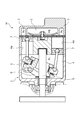
図2に示されるように、容量制御弁Vは容量可変型圧縮機Mに組み込まれている。ソレノイド80を構成するコイル86に通電する電流が調整されることで、容量制御弁Vにおける主弁50、副弁55、CS弁57は開閉制御される。これとともに、中間連通路59における吸入圧力Psにより感圧体61が動作されることで、感圧弁53は開閉制御される。これらにより、制御室4内に流入する、または制御室4から流出する流体は制御される。これを利用して制御室4内の制御圧力Pcは可変制御される。
本実施例において、主弁50は、主弁体としての主副弁体51と主弁座10aとにより構成されている。主弁座10aはバルブハウジング10における内周面に形成されている。主副弁体51における軸方向左端面51aが主弁座10aに接離することで、主弁50は開閉するようになっている。感圧弁53は、キャップ70と感圧弁座52aとにより構成されている。キャップ70は感圧体61を構成する部材でもある。感圧弁座52aは感圧弁部材52における軸方向左端面に形成されている。キャップ70の軸方向右端における内径側に形成されるシール面70aが感圧弁座52aに接離することで、感圧弁53は開閉するようになっている。副弁55は、主副弁体51と副弁座82aとにより構成されている。副弁座82aは固定鉄心82における開口端面、すなわち軸方向左端面に形成されている。主副弁体51における軸方向右端面51bが副弁座82aに接離することで、副弁55は開閉するようになっている。CS弁57は、CS弁体56とガイド面10eとにより構成されている。ガイド面10eはバルブハウジング10における内周面に形成されている。CS弁体56における外周面56aがガイド面10eに対して軸方向にスライド摺動することで、CS弁体56に設けられる連通孔56f(図3~図5参照)は開閉されるようになっている。尚、CS弁57については後段にて詳述する。
次いで、容量制御弁Vの構造について説明する。図2に示されるように、容量制御弁Vは、バルブハウジング10と、主副弁体51と、感圧弁部材52と、当接部材54と、CS弁体56と、感圧体61と、ソレノイド80と、から主に構成されている。バルブハウジング10は、金属材料または樹脂材料により形成されている。主副弁体51、感圧弁部材52、当接部材54、CS弁体56は、バルブハウジング10内に軸方向に往復動自在に配置されている。感圧体61は、中間連通路59における吸入圧力Psに応じて主副弁体51、感圧弁部材52、当接部材54に軸方向右方への付勢力を付与する。ソレノイド80は、バルブハウジング10に接続され主副弁体51、感圧弁部材52、当接部材54、CS弁体56に駆動力を及ぼす。
図2に示されるように、ソレノイド80は、ケーシング81と、固定鉄心82と、駆動ロッド83と、可動鉄心84と、コイルスプリング85と、コイル86と、から主に構成されている。ケーシング81は、軸方向左方に開放する開口部81aを有している。固定鉄心82は、略円筒形状に形成されており、ケーシング81における開口部81aに対して軸方向左方から挿入されケーシング81の内径側に固定されている。駆動ロッド83は、固定鉄心82における内径側において軸方向に往復動自在、かつその軸方向左端部が主副弁体51における軸方向右端部と接続固定されている。可動鉄心84は、駆動ロッド83における軸方向右端部に固着されている。コイルスプリング85は、固定鉄心82と可動鉄心84との間に設けられ可動鉄心84を軸方向右方に付勢している。励磁用のコイル86は、固定鉄心82の外側にボビンを介して巻き付けられている。
ケーシング81の軸方向左端部における内径側には軸方向右方に凹む凹部81bが形成されている。ケーシング81には、凹部81bに対してバルブハウジング10の軸方向右端部が略密封状に挿嵌・固定されている。
固定鉄心82は、鉄やケイ素鋼等の磁性材料である剛体から形成されている。固定鉄心82は、円筒部82bと、フランジ部82dとを備えている。円筒部82bは、軸方向に延び駆動ロッド83が挿通される挿通孔82cが形成されている。フランジ部82dは、円筒部82bにおける軸方向左端部の外周面から外径方向に延びている環状である。また、円筒部82bにおける軸方向左端面には副弁座82aが形成されている。
図2に示されるように、バルブハウジング10には、ソレノイド80側から順に、吐出ポートとしてのPdポート12と、吸入ポートとしての第1Psポート13と、制御ポートとしてのPcポート14と、吸入ポートとしての第2Psポート15と、が形成されている。Pdポート12は、容量可変型圧縮機Mにおける吐出室2と連通している。第1Psポート13は容量可変型圧縮機Mにおける吸入室3と連通している。Pcポート14は容量可変型圧縮機Mにおける制御室4と連通している。第2Psポート15は容量可変型圧縮機Mにおける吸入室3と連通している。
また、バルブハウジング10は、その軸方向左端部に仕切調整部材11が略密封状に圧入されることにより有底略円筒形状を成している。尚、バルブハウジング10の軸方向における設置位置が調整されることで、仕切調整部材11は、後述するバネとしてのコイルスプリング91の付勢力を調整できるようになっている。
バルブハウジング10の内部には、主副弁体51、感圧弁部材52、当接部材54、CS弁体56が軸方向に往復動自在に配置されている。バルブハウジング10の第1Psポート13とPdポート12との間における内周面には、主副弁体51の外周面が略密封状態で摺接可能な小径のガイド面10bが形成されている。また、バルブハウジング10における内周面の軸方向左端部には、軸方向断面略ハット形状の環状段部10fが形成されている(図3~図5参照)。環状段部10fは、内周面10cと、環状の溝10dと、ガイド面10eとにより形成されている。内周面10cは、バルブハウジング10における軸方向左端面から軸方向右方に延びている。ガイド面10eは、環状の溝10dの軸方向右端から軸方向右方に延びる内周面に形成されている。尚、ガイド面10eは、CS弁体56における外周面56aに摺接する弁座としての機能も有している。また、環状の溝10dの底には前述の第2Psポート15が形成されている。
また、バルブハウジング10の内部には、第1弁室20と、第2弁室30と、感圧室40とが形成されている。第1弁室20と、第2弁室30と、感圧室40には、それぞれPdポート12、第1Psポート13、Pcポート14が連通されている。また、第1弁室20には、主副弁体51における軸方向左端面51a側が配置されている。第2弁室30には、主副弁体51における背圧側、すなわち軸方向右端面51b側が配置されている。感圧室40には、感圧体61と共にCS弁体56が配置されている。尚、主副弁体51における外周面と、固定鉄心82における軸方向左端面と、バルブハウジング10におけるガイド面10bよりも軸方向右側の内周面とにより、第2弁室30は画成されている。
図2に示されるように、感圧体61は、ベローズコア62と、キャップ70と、から主に構成されている。ベローズコア62にはコイルスプリング63が内蔵されている。キャップ70は円板状であり、ベローズコア62における軸方向右端に設けられている。ベローズコア62における軸方向左端は、仕切調整部材11に固定されている。
また、感圧体61は、感圧室40内に配置されている。コイルスプリング63とベローズコア62によりキャップ70を軸方向右方に移動させる付勢力により、キャップ70におけるシール面70aは感圧弁部材52における感圧弁座52aに着座するようになっている。
図2および図3に示されるように、主副弁体51は、略円筒形状に構成されている。主副弁体51における軸方向左端部には、感圧弁部材52が接続固定されている。主副弁体51における軸方向右端部には、駆動ロッド83が接続固定されている。これらは共に軸方向に移動するようになっている。尚、主副弁体51における外周面とバルブハウジング10におけるガイド面10bとの間には、径方向に僅かに離間することにより微小な隙間が形成されている。この隙間により、主副弁体51は、バルブハウジング10に対して摺動して軸方向に円滑に相対移動可能となっている。
また、主副弁体51および感圧弁部材52の内部には、中空孔が接続されることにより軸方向に亘って貫通する中間連通路59が形成されている。尚、駆動ロッド83における軸方向左端部に形成されている連通孔83aを介して中間連通路59は、第2弁室30と連通可能となっている(図2参照)。尚、説明の便宜上、図示を省略するが、容量可変型圧縮機Mが停止状態で長時間放置されることにより制御室4で高圧となった流体は液化することがある。このような状態において容量可変型圧縮機Mを起動するとともに容量制御弁Vを通電状態とすることにより、容量制御弁Vでは主弁50が閉塞されるとともに副弁55が開放される。さらに中間連通路59における高い吸入圧力Psにより、感圧体61が収縮して感圧弁53は開弁される。これらにより、中間連通路59を介して制御室4の液冷媒は、吸入室3に短時間で排出されるようになっている。
図3~図5に示されるように、感圧弁部材52は、第1円筒部52bと、フランジ部52cと、第2円筒部52dと、当接部52eと、を有するフランジ付き略円筒形状に構成されている。第1円筒部52bは、主副弁体51における軸方向左端部が接続固定されている。フランジ部52cは、第1円筒部52bにおける軸方向左端部の外周面から外径方向に延びる環状に形成されている。第2円筒部52dは、フランジ部52cの軸方向左側においてフランジ部52cよりも小径に形成され当接部材54における軸方向右端部が接続固定されている。当接部52eは、第2円筒部52dにおける軸方向左側において第2円筒部52dよりも小径に形成されている。また、当接部52eには、感圧体61を構成するキャップ70におけるシール面70aと接離する感圧弁座52aが形成されている。
図3~図5に示されるように、当接部材54は、略円筒形状に構成されている。また、当接部材54は、感圧体61を構成するキャップ70よりも大径に形成されている。当接部材54における軸方向右端部には、感圧弁部材52における第2円筒部52dが接続固定されている。これにより、主副弁体51、感圧弁部材52は共に軸方向に移動するようになっている。また、当接部材54における軸方向左端面54aは、CS弁体56における軸方向右端部に形成される凹部56cの底面に軸方向に当接している。また、当接部材54における軸方向左端部には、径方向に貫通する貫通孔54bが設けられている。貫通孔54bは、感圧室40において当接部材54の内径側と外径側とを連通している。
図3~図5に示されるように、CS弁体56は、基部56bと、凹部56cと、延出部56dと、突出部56eと、から段付き円筒形状に構成されている。基部56bは、感圧室40内において感圧体61よりも大径で同心状に配置されており、かつ略円筒形状に形成されている。凹部56cは、基部56bの軸方向右端内径側が軸方向左方に凹む環状に形成されている。延出部56dは、基部56bの軸方向左端における外径側から軸方向左方に延びる略円筒形状に形成されている。突出部56eは、延出部56dにおける軸方向左端部の外周面から外径方向に突出する環状に形成されている。
尚、CS弁体56における外周面56a、すなわち基部56bにおける外周面とバルブハウジング10における内周面に形成されるガイド面10eとの間、突出部56eにおける外周面とバルブハウジング10における内周面10cとの間には、径方向に離間することにより微小な隙間がそれぞれ形成されている。これらの隙間により、CS弁体56は、バルブハウジング10に対して摺動して軸方向に円滑に相対移動可能となっている。
また、CS弁体56における外周面56a、すなわち基部56bにおける外周面とバルブハウジング10におけるガイド面10eとの間には、クリアランスシールによる密封部Saが形成されている。また、突出部56eにおける外周面とバルブハウジング10における内周面10cとの間には、クリアランスシールによる密封部Sbが形成されている。すなわち、第2Psポート15に対して軸方向両側に密封部Sa,Sbがそれぞれ形成されている。
また、CS弁体56には、突出部56eが設けられている。これにより、バルブハウジング10とCS弁体56との間には、環状の空間60が形成されている。空間60は、密封部Sa,Sbにより感圧室40との間をシールされており、第2Psポート15により容量可変型圧縮機Mにおける吸入室3と連通されている。
また、CS弁体56における基部56bの軸方向略中央部には、径方向に貫通する複数の連通孔56fが設けられている。複数の連通孔56fは、CS弁体56における内径側と外径側で感圧室40と空間60とを連通可能となっている。連通孔56fは、開口形状が円(図3~図5における吹き出し表示部分参照)かつ内径一定の貫通孔により構成されている。これにより、CS弁体56に対する連通孔56fの加工形成を行いやすくなっている。尚、連通孔56fの開口形状は、円に限らず、例えば半円等の円形の一部から形成されてもよく、円形以外、例えば三角形や楕円形に形成されてもよい。
また、CS弁体56における軸方向右端に形成される凹部56cの底面には、当接部材54における軸方向左端面54aが軸方向に当接している。尚、凹部56cの内周面における内径は、当接部材54における外径よりも大きく形成されている。これにより、凹部56cにおける内周面から内径側に離間した状態で、当接部材54は凹部56cにおける底面に軸方向にのみ当接している。
また、CS弁体56の内側には、軸方向左端部に基部56bと延出部56dとの内径差により凹部56gが形成されている。また、凹部56gには、コイルスプリング91における軸方向右端部が内嵌されている。コイルスプリング91は、感圧体61やCS弁57を構成している。
尚、コイルスプリング91における軸方向右端は、凹部56gにおける底面に当接している。コイルスプリング91における軸方向左端は、仕切調整部材11における内径側に形成される凹部11bの底面に当接している。これらにより、コイルスプリング91はCS弁体56をCS弁57の閉弁方向である軸方向右方に付勢している。また、コイルスプリング91は圧縮バネである。
また、CS弁体56における軸方向左端、すなわち延出部56dにおける軸方向左端56hは、CS弁57の開弁時において仕切調整部材11における軸方向右端面11aに近接可能となっている(図5参照)。
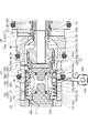
次いで、CS弁57の開閉機構について説明する。図3に示されるように、ソレノイド80への非通電時において主弁50が全開される主副弁体51の開弁位置にある状態において、CS弁体56には、コイルスプリング91により閉弁方向である軸方向右方に付勢力(図3において白矢印で図示)が作用している。このとき、連通孔56fは、バルブハウジング10における環状の溝10dの軸方向右端よりも軸方向右方に離間している。また、凹部56cにおける底面は当接部材54における軸方向左端面54aに当接している。また、CS弁体56における外周面56aは、連通孔56fにおける全周において少なくとも軸方向左側でガイド面10eとクリアランスシールによる密封部Saを形成している。すなわち、密封部Saにより連通孔56fは全閉されている。また、CS弁体56における突出部56eの外周面とバルブハウジング10における内周面10cとの間には、クリアランスシールによる密封部Sbが形成されている。このように、密封部Sa,SbによりCS弁57は全閉となっている。尚、図3~図5における吹き出し表示部分には、CS弁体56の内径側から見た連通孔56fの開度、すなわちCS弁57の開度が示されている。また、図3~図5における吹き出し表示部分では、CS弁57における密封部Saによる連通孔56fの開口における閉塞部分をドットにより模式的に示している。
また、主弁50が開放された状態からソレノイド80に通電されると、主副弁体51は軸方向左方に移動する。図4に示されるように、主副弁体51の左方への移動により、感圧弁部材52、当接部材54、CS弁体56は軸方向左方に押圧されて共に移動する。この移動に応じてコイルスプリング91は縮む。これらにより、ストローク位置P(図6参照)に到達するまでは、すなわちCS弁体56における連通孔56fの軸方向左端が環状の溝10dにおける軸方向右端と径方向に重なるストローク位置Pに到達するまでは、CS弁57における密封部Saにより連通孔56fは全閉されている。そして、主副弁体51がストローク位置Pからさらに左方へ移動すると、感圧弁部材52、当接部材54、CS弁体56はさらに軸方向左方に押圧されて共に移動する。これに応じてコイルスプリング91はさらに縮む。これらにより、連通孔56fは開放され始める。すなわち、連通孔56fの開口における一部が開放され始める(図4における吹き出し表示部参照)。このとき、主弁50はまだ閉塞されていない。
ソレノイド80への通電時における最大通電状態においては、図5に示されるように、主副弁体51はさらに軸方向左方に移動する。これにより、主副弁体51が閉弁位置まで移動し、主副弁体51における軸方向左端面51aが主弁座10aに当接し、主弁50は全閉となる。主副弁体51が閉弁位置にある状態では、CS弁体56における軸方向左端56hが仕切調整部材11の軸方向右端面11aに近接する位置に移動する。すなわちCS弁体56は最も開方向に最大のストローク位置となって、連通孔56fは全開される。このとき、CS弁57における密封部Saにより連通孔56fは、開口における略半分が閉塞されている(図5における吹き出し表示部参照)。
次いで、容量制御弁Vの動作について、通電時の最大通電状態(起動時)、非通電時、通常制御時の順に説明する。
先ず、通電時における最大通電状態(起動時)について説明する。容量可変型圧縮機Mを使用せずに長時間放置した後、容量可変型圧縮機Mを起動するとともに容量制御弁Vにおけるソレノイド80に通電することにより、容量制御弁Vでは主弁50が全閉され副弁55が全開される。このとき、図5に示されるように、主副弁体51が閉弁位置までストロークすることにより、感圧弁部材52、当接部材54、CS弁体56は軸方向左方に共に移動する。そして、CS弁体56における軸方向左端56hが仕切調整部材11の軸方向右端面11aに近接し、連通孔56fは全開となる。これにより、Pcポート14と第2Psポート15とが連通された状態となり、制御室4内の液化した流体は連通孔56fを通して吸入室3内に短時間で排出される。よって、容量制御弁Vは、起動時における容量可変型圧縮機Mの応答性を高めることができる。また、主弁50の全閉時において、CS弁57により連通孔56fが全開されることにより、連通孔56fを通して排出される流体の流量は最大となる。このように、容量制御弁Vは、起動時における容量可変型圧縮機Mの応答性をより高めることができる。さらに、中間連通路59における吸入圧力Psが高いことから、前述したように、感圧弁53は開放される。これにより、容量制御弁Vは、制御圧力Pcを中間連通路59および駆動ロッド83の連通孔83aを通して第2弁室30に迅速にリリースすることができる。これらのように、CS弁57と感圧弁53とにより開放される2つの流路を利用して、制御室4内から液化した流体を吸入室3内に短時間で排出させる容量制御弁Vは、起動時の容量可変型圧縮機Mの応答性を高めることができる。
さらに、本実施例の容量制御弁Vは、制御室4が最大容量の状態においても、主弁50を閉塞し、CS弁57により連通孔56fを開放しPcポート14と第2Psポート15とを連通させる。これにより、本実施例の容量制御弁Vは、制御圧力Pcと吸入圧力Psを均圧(同圧)に維持することができる。そのため、制御室4のシリンダ4a内におけるピストン7のストロークは安定する。よって、容量制御弁Vは、制御室4において最大容量の状態を維持させ、容量可変型圧縮機Mの運転効率を高めることができる。
次に、非通電時について説明する。非通電時においては、図3に示されるように、主副弁体51、感圧弁部材52、当接部材54は感圧体61の付勢力により軸方向右方へと押圧される。そのため、主弁50は全開となる。これとともに、コイルスプリング91から閉弁方向である軸方向右方に付勢力が作用するCS弁体56は閉弁位置となる。これに伴って、CS弁57における密封部Saにより連通孔56fは全閉される。これらによれば、CS弁57における密封部Saにより連通孔56fは閉塞される。すなわち、Pcポート14を通過する制御流体は第2Psポート15に流入することがない。そのため、容量可変型圧縮機Mを停止して短い時間経過後の再起動時における容量可変型圧縮機Mの制御性が高く、また容量制御弁Vの運転効率が高い。
次に、通常制御時について説明する。通常制御時においては、容量制御弁Vのデューティ制御により、主弁50の開度や開放時間は調整される。これにより、容量制御弁Vは、Pdポート12からPcポート14への流体の流量を制御している。容量制御弁Vのデューティ制御において主弁50が僅かに開いた際にも、主副弁体51はストローク位置P(図6参照)よりも開弁位置側にストロークする。これにより、CS弁体56には、コイルスプリング91から閉弁方向である軸方向右方に付勢力が作用する。CS弁57における密封部Saにより連通孔56fは全閉された状態が維持される。このことから、主副弁体51の開弁位置からストローク位置Pまでのストロークにおいて、連通孔56fを通したPcポート14から第2Psポート15への流体の漏れが防止されている。そのため、容量制御弁Vは容量可変型圧縮機Mにおける制御圧力Pcの制御精度を高めることができる。
また、主副弁体51がストローク位置P(図6参照)まで移動すると、主副弁体51と共に移動するCS弁体56における連通孔56fの軸方向左端は、環状の溝10dにおける軸方向右端と径方向に重なる。それから、さらに主副弁体51が移動し主弁50が全閉するまでの間に、主弁50は徐々に閉塞されていくとともに、CS弁57により連通孔56fは徐々に開放されていく。これにより、主副弁体51のストローク位置Pから閉弁位置までの間において、主弁50とCS弁57(すなわち連通孔56f)とが共に開放される領域は設定することができる。また、主弁50と連通孔56fとの開口面積のバランスは、主副弁体51のストローク位置に応じて調整可能である。
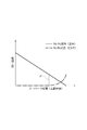
また、主弁50は、主副弁体51のストローク位置に応じて開口面積が比例的に増減する、いわゆるポペット弁構造を成す。CS弁57は主副弁体51のストローク位置に応じて主副弁体51と共に移動するCS弁体56の外周面56aとガイド面10eとが摺接する密封部Saを有する。このように、主弁50とは異なり、CS弁57はスプール弁構造であって、CS弁体56に設けられる連通孔56fにおける開口面積は増減される。そのため、図6に示されるように、連通孔56fは全閉状態から開き始めると略指数関数的に開度が大きくなる。尚、略指数関数的に限らず、連通孔56fの開度はCS弁57による連通孔56fの全閉状態直後の開き始めよりも全開状態直前の全開前において、主副弁体51のストロークに対する連通孔56fの開度の増加率が大きくなるものであることが好ましい(図6参照)。すなわち、主副弁体51がストローク位置P(図6参照)付近をストロークする通常制御時には、CS弁57により主副弁体51のストロークに対する連通孔56fの開度の増加率を小さく抑えることができる。そのため、通常制御時におけるCS弁57は連通孔56fを通したPcポート14から第2Psポート15への流体の漏れを低減することができる。これにより、容量制御弁Vは、容量可変型圧縮機Mにおける制御圧力Pcを低下させる制御の応答性を高めることができる。さらに、主弁50の全閉時にCS弁57により連通孔56fは全開される。これにより、連通孔56fを通して排出される流体の流量は最大となる。そのため、起動時における制御室4からの液冷媒の排出や通常制御時における制御室4の最大容量時において、容量制御弁Vは、制御圧力Pcを速やかに低下させることができる。尚、主弁50の全閉時にCS弁57は全開されなくてもよい。
また、連通孔56fの開口形状は、円により形成されている。そのため、連通孔56fの開度は主副弁体51のストロークに応じて緩やかな曲線状に漸増する(図6参照)。これにより、通常制御時における流体の漏れは低減する。加えて、連通孔56fの開口面積は全開状態から素早く小さくなる。
また、CS弁体56の軸方向における連通孔56fの形成位置を変更することにより、ストローク位置P(図6参照)は調整される。また、連通孔56fの形状や大きさを変更することにより、主副弁体51のストロークに応じた連通孔56fの開度の増加率や最大開口面積は適宜調整される。
また、本実施例では、図5に示されるように、CS弁57による連通孔56fの全開状態において、円により形成される連通孔56fの開口は半分だけ開放される。これにより、容量制御弁Vの制御は主副弁体51のストロークの精度に影響され難い。
また、容量制御弁Vでは、主弁50を構成する主副弁体51と、CS弁57を構成するCS弁体56が分離可能な別部材により構成されている。これにより、主副弁体51とCS弁体56は独立して軸心を取ることができるため、互いの動作への影響が抑えられている。このことから、主弁50およびCS弁57の開度は、それぞれ精度良く調整される。
また、CS弁体56は、当接部材54における軸方向左端面54aと軸方向のみで当接している。このことから、主副弁体51とCS弁体56との間の軸心の傾きやずれによる互いの動作への影響が抑えられている。
また、CS弁体56は、コイルスプリング91によりCS弁57の閉弁方向である軸方向右方に付勢されている。そのため、主弁50を開放させる際にCS弁体56は主副弁体51、感圧弁部材52、当接部材54に追従する。このことからCS弁57は確実に閉塞される。
また、CS弁体56は、略円筒形状である。バルブハウジング10の内周には環状段部10fが形成されている。また、環状段部10fの一部はCS弁体56の外周面56aが摺接するガイド面10eを構成している。そのためCS弁57を有する容量制御弁Vは簡素な構造となる。
また、ソレノイド80への通電時の最大通電状態においてCS弁57により連通孔56fが全開された状態では、主副弁体51における軸方向左端面51aが主弁座10aに当接して主弁50は全閉される。これにより、連通孔56fの最大開口面積は決定されている。そのため、CS弁57を有する容量制御弁Vは簡素な構造となる。
また、容量制御弁Vにおいては、バルブハウジング10の軸方向左側から感圧室40にCS弁体56、コイルスプリング91が挿入された後、バルブハウジング10の軸方向左端部に仕切調整部材11が圧入されて固定される。このような構造であるため、容量制御弁Vの組み立てが簡単である。
また、Pcポート14は、第2Psポート15よりもPdポート12に近い位置に配置されている。そのため、容量制御弁Vにおいては、通常制御時に吐出圧力Pdを制御室4に伝えやすい。
以上、本発明の実施例を図面により説明してきたが、具体的な構成はこれら実施例に限られるものではなく、本発明の要旨を逸脱しない範囲における変更や追加があっても本発明に含まれる。
例えば、前記実施例では、主副弁体51、感圧弁部材52、当接部材54、CS弁体56が別体に構成される構成について説明したが、これに限らず、例えば主副弁体51と感圧弁部材52が一体に、また当接部材54とCS弁体56が一体に構成されていてもよい。また、主副弁体51、感圧弁部材52、当接部材54およびCS弁体56が全て一体に構成されていてもよい。
また、容量可変型圧縮機Mにおける制御室4と吸入室3とを直接連通する連通路および固定オリフィスは設けなくてもよい。
また、前記実施例では、副弁は設けなくともよい。また、主副弁体における軸方向右端は、軸方向の荷重を受ける支持部材として機能すればよく、必ずしも密閉機能は必要ではない。
また、バネとしてのコイルスプリング91は、圧縮バネに限らず、引張バネでもよく、コイル形状以外であってもよい。
また、感圧体61は、内部にコイルスプリングを使用しないものであってもよい。
1 ケーシング
2 吐出室
3 吸入室
4 制御室
10 バルブハウジング
10a 主弁座
10b ガイド面
10c 内周面
10d 溝
10e ガイド面
10f 環状段部
11 仕切調整部材
11a 軸方向右端面
11b 凹部
12 Pdポート(吐出ポート)
13 第1Psポート(吸入ポート)
14 Pcポート(制御ポート)
15 第2Psポート(吸入ポート)
20 第1弁室
30 第2弁室
40 感圧室
50 主弁
51 主副弁体(主弁体)
51a 軸方向左端
51b 軸方向右端
52 感圧弁部材
52a 感圧弁座
52b 円筒部
52c フランジ部
52d 第2円筒部
52e 当接部
53 感圧弁
54 当接部材
55 副弁
56 CS弁体
56a 外周面
56b 基部
56c 凹部
56d 延出部
56e 突出部
56f 連通孔
56g 凹部
56h 軸方向左端
57 CS弁
59 中間連通路
60 空間
61 感圧体
62 ベローズコア
63 コイルスプリング
70 キャップ
70a シール面
80 ソレノイド
82 固定鉄心
82a 副弁座
91 コイルスプリング(バネ)
Pc 制御圧力
Pd 吐出圧力
Ps 吸入圧力
Sa,Sb 密封部
V 容量制御弁
2 吐出室
3 吸入室
4 制御室
10 バルブハウジング
10a 主弁座
10b ガイド面
10c 内周面
10d 溝
10e ガイド面
10f 環状段部
11 仕切調整部材
11a 軸方向右端面
11b 凹部
12 Pdポート(吐出ポート)
13 第1Psポート(吸入ポート)
14 Pcポート(制御ポート)
15 第2Psポート(吸入ポート)
20 第1弁室
30 第2弁室
40 感圧室
50 主弁
51 主副弁体(主弁体)
51a 軸方向左端
51b 軸方向右端
52 感圧弁部材
52a 感圧弁座
52b 円筒部
52c フランジ部
52d 第2円筒部
52e 当接部
53 感圧弁
54 当接部材
55 副弁
56 CS弁体
56a 外周面
56b 基部
56c 凹部
56d 延出部
56e 突出部
56f 連通孔
56g 凹部
56h 軸方向左端
57 CS弁
59 中間連通路
60 空間
61 感圧体
62 ベローズコア
63 コイルスプリング
70 キャップ
70a シール面
80 ソレノイド
82 固定鉄心
82a 副弁座
91 コイルスプリング(バネ)
Pc 制御圧力
Pd 吐出圧力
Ps 吸入圧力
Sa,Sb 密封部
V 容量制御弁
Claims (6)
- 吐出圧力の吐出流体が通過する吐出ポート、吸入圧力の吸入流体が通過する吸入ポートおよび制御圧力の制御流体が通過する制御ポートが形成されたバルブハウジングと、
ソレノイドにより駆動される主弁体、および前記吐出ポートと前記制御ポートとの間に設けられ前記主弁体が接触可能な主弁座により構成される主弁と、を備える容量制御弁であって、
連通孔が形成され、前記主弁体と連動し前記バルブハウジングにスライド摺動するCS弁体を有し、前記CS弁体のスライド位置に応じて前記連通孔が前記制御ポートと前記吸入ポート間の流路を連通可能とするCS弁を備えている容量制御弁。 - 前記CS弁体は、前記主弁体と分離可能な別部材により構成されている請求項1に記載の容量制御弁。
- 前記主弁体と前記CS弁体は、軸方向のみ当接可能となっている請求項2に記載の容量制御弁。
- 前記CS弁体は、バネにより閉方向に付勢されている請求項2または3に記載の容量制御弁。
- 前記連通孔は径方向に貫通する孔であり、その開口形状は、円形の一部から形成されている請求項1ないし4のいずれかに記載の容量制御弁。
- 前記連通孔の開口形状は、円である請求項5に記載の容量制御弁。
Priority Applications (1)
| Application Number | Priority Date | Filing Date | Title |
|---|---|---|---|
| JP2022535294A JP7638610B2 (ja) | 2020-07-07 | 2021-07-02 | 容量制御弁 |
Applications Claiming Priority (2)
| Application Number | Priority Date | Filing Date | Title |
|---|---|---|---|
| JP2020117314 | 2020-07-07 | ||
| JP2020-117314 | 2020-07-07 |
Publications (1)
| Publication Number | Publication Date |
|---|---|
| WO2022009795A1 true WO2022009795A1 (ja) | 2022-01-13 |
Family
ID=79552602
Family Applications (1)
| Application Number | Title | Priority Date | Filing Date |
|---|---|---|---|
| PCT/JP2021/025135 Ceased WO2022009795A1 (ja) | 2020-07-07 | 2021-07-02 | 容量制御弁 |
Country Status (2)
| Country | Link |
|---|---|
| JP (1) | JP7638610B2 (ja) |
| WO (1) | WO2022009795A1 (ja) |
Citations (2)
| Publication number | Priority date | Publication date | Assignee | Title |
|---|---|---|---|---|
| WO2020013155A1 (ja) * | 2018-07-12 | 2020-01-16 | イーグル工業株式会社 | 容量制御弁 |
| WO2020013156A1 (ja) * | 2018-07-12 | 2020-01-16 | イーグル工業株式会社 | 容量制御弁 |
Family Cites Families (1)
| Publication number | Priority date | Publication date | Assignee | Title |
|---|---|---|---|---|
| JP6924476B2 (ja) | 2017-04-07 | 2021-08-25 | 株式会社テージーケー | 可変容量圧縮機用制御弁 |
-
2021
- 2021-07-02 WO PCT/JP2021/025135 patent/WO2022009795A1/ja not_active Ceased
- 2021-07-02 JP JP2022535294A patent/JP7638610B2/ja active Active
Patent Citations (2)
| Publication number | Priority date | Publication date | Assignee | Title |
|---|---|---|---|---|
| WO2020013155A1 (ja) * | 2018-07-12 | 2020-01-16 | イーグル工業株式会社 | 容量制御弁 |
| WO2020013156A1 (ja) * | 2018-07-12 | 2020-01-16 | イーグル工業株式会社 | 容量制御弁 |
Also Published As
| Publication number | Publication date |
|---|---|
| JPWO2022009795A1 (ja) | 2022-01-13 |
| JP7638610B2 (ja) | 2025-03-04 |
Similar Documents
| Publication | Publication Date | Title |
|---|---|---|
| EP3822485B1 (en) | Capacity control valve | |
| JP7066063B2 (ja) | 容量制御弁 | |
| JPWO2020110925A1 (ja) | 容量制御弁 | |
| EP3822484B1 (en) | Capacity control valve | |
| CN111684157B (zh) | 容量控制阀 | |
| JP7504989B2 (ja) | 容量制御弁 | |
| WO2021241477A1 (ja) | 容量制御弁 | |
| KR102744360B1 (ko) | 용량 제어 밸브 | |
| JPWO2020013154A1 (ja) | 容量制御弁 | |
| JPWO2020116435A1 (ja) | 容量制御弁 | |
| EP3822483B1 (en) | Capacity control valve | |
| JPWO2020116436A1 (ja) | 容量制御弁 | |
| JPWO2020095918A1 (ja) | 容量制御弁 | |
| JP7638610B2 (ja) | 容量制御弁 | |
| JP7423169B2 (ja) | 容量制御弁 | |
| WO2020204131A1 (ja) | 容量制御弁 | |
| JP7337453B2 (ja) | 容量制御弁 |
Legal Events
| Date | Code | Title | Description |
|---|---|---|---|
| 121 | Ep: the epo has been informed by wipo that ep was designated in this application |
Ref document number: 21838280 Country of ref document: EP Kind code of ref document: A1 |
|
| ENP | Entry into the national phase |
Ref document number: 2022535294 Country of ref document: JP Kind code of ref document: A |
|
| NENP | Non-entry into the national phase |
Ref country code: DE |
|
| 122 | Ep: pct application non-entry in european phase |
Ref document number: 21838280 Country of ref document: EP Kind code of ref document: A1 |