WO2022009484A1 - Film forming method - Google Patents
Film forming method Download PDFInfo
- Publication number
- WO2022009484A1 WO2022009484A1 PCT/JP2021/011719 JP2021011719W WO2022009484A1 WO 2022009484 A1 WO2022009484 A1 WO 2022009484A1 JP 2021011719 W JP2021011719 W JP 2021011719W WO 2022009484 A1 WO2022009484 A1 WO 2022009484A1
- Authority
- WO
- WIPO (PCT)
- Prior art keywords
- substrate
- rotary targets
- magnet
- rotary
- angle
- Prior art date
Links
Images


Classifications
-
- C—CHEMISTRY; METALLURGY
- C23—COATING METALLIC MATERIAL; COATING MATERIAL WITH METALLIC MATERIAL; CHEMICAL SURFACE TREATMENT; DIFFUSION TREATMENT OF METALLIC MATERIAL; COATING BY VACUUM EVAPORATION, BY SPUTTERING, BY ION IMPLANTATION OR BY CHEMICAL VAPOUR DEPOSITION, IN GENERAL; INHIBITING CORROSION OF METALLIC MATERIAL OR INCRUSTATION IN GENERAL
- C23C—COATING METALLIC MATERIAL; COATING MATERIAL WITH METALLIC MATERIAL; SURFACE TREATMENT OF METALLIC MATERIAL BY DIFFUSION INTO THE SURFACE, BY CHEMICAL CONVERSION OR SUBSTITUTION; COATING BY VACUUM EVAPORATION, BY SPUTTERING, BY ION IMPLANTATION OR BY CHEMICAL VAPOUR DEPOSITION, IN GENERAL
- C23C14/00—Coating by vacuum evaporation, by sputtering or by ion implantation of the coating forming material
- C23C14/22—Coating by vacuum evaporation, by sputtering or by ion implantation of the coating forming material characterised by the process of coating
- C23C14/34—Sputtering
- C23C14/35—Sputtering by application of a magnetic field, e.g. magnetron sputtering
- C23C14/352—Sputtering by application of a magnetic field, e.g. magnetron sputtering using more than one target
-
- C—CHEMISTRY; METALLURGY
- C23—COATING METALLIC MATERIAL; COATING MATERIAL WITH METALLIC MATERIAL; CHEMICAL SURFACE TREATMENT; DIFFUSION TREATMENT OF METALLIC MATERIAL; COATING BY VACUUM EVAPORATION, BY SPUTTERING, BY ION IMPLANTATION OR BY CHEMICAL VAPOUR DEPOSITION, IN GENERAL; INHIBITING CORROSION OF METALLIC MATERIAL OR INCRUSTATION IN GENERAL
- C23C—COATING METALLIC MATERIAL; COATING MATERIAL WITH METALLIC MATERIAL; SURFACE TREATMENT OF METALLIC MATERIAL BY DIFFUSION INTO THE SURFACE, BY CHEMICAL CONVERSION OR SUBSTITUTION; COATING BY VACUUM EVAPORATION, BY SPUTTERING, BY ION IMPLANTATION OR BY CHEMICAL VAPOUR DEPOSITION, IN GENERAL
- C23C14/00—Coating by vacuum evaporation, by sputtering or by ion implantation of the coating forming material
- C23C14/22—Coating by vacuum evaporation, by sputtering or by ion implantation of the coating forming material characterised by the process of coating
- C23C14/34—Sputtering
- C23C14/3407—Cathode assembly for sputtering apparatus, e.g. Target
-
- C—CHEMISTRY; METALLURGY
- C23—COATING METALLIC MATERIAL; COATING MATERIAL WITH METALLIC MATERIAL; CHEMICAL SURFACE TREATMENT; DIFFUSION TREATMENT OF METALLIC MATERIAL; COATING BY VACUUM EVAPORATION, BY SPUTTERING, BY ION IMPLANTATION OR BY CHEMICAL VAPOUR DEPOSITION, IN GENERAL; INHIBITING CORROSION OF METALLIC MATERIAL OR INCRUSTATION IN GENERAL
- C23C—COATING METALLIC MATERIAL; COATING MATERIAL WITH METALLIC MATERIAL; SURFACE TREATMENT OF METALLIC MATERIAL BY DIFFUSION INTO THE SURFACE, BY CHEMICAL CONVERSION OR SUBSTITUTION; COATING BY VACUUM EVAPORATION, BY SPUTTERING, BY ION IMPLANTATION OR BY CHEMICAL VAPOUR DEPOSITION, IN GENERAL
- C23C14/00—Coating by vacuum evaporation, by sputtering or by ion implantation of the coating forming material
- C23C14/22—Coating by vacuum evaporation, by sputtering or by ion implantation of the coating forming material characterised by the process of coating
- C23C14/34—Sputtering
- C23C14/35—Sputtering by application of a magnetic field, e.g. magnetron sputtering
-
- H—ELECTRICITY
- H01—ELECTRIC ELEMENTS
- H01J—ELECTRIC DISCHARGE TUBES OR DISCHARGE LAMPS
- H01J37/00—Discharge tubes with provision for introducing objects or material to be exposed to the discharge, e.g. for the purpose of examination or processing thereof
- H01J37/32—Gas-filled discharge tubes
- H01J37/34—Gas-filled discharge tubes operating with cathodic sputtering
- H01J37/3411—Constructional aspects of the reactor
- H01J37/3414—Targets
- H01J37/3417—Arrangements
-
- H—ELECTRICITY
- H01—ELECTRIC ELEMENTS
- H01J—ELECTRIC DISCHARGE TUBES OR DISCHARGE LAMPS
- H01J37/00—Discharge tubes with provision for introducing objects or material to be exposed to the discharge, e.g. for the purpose of examination or processing thereof
- H01J37/32—Gas-filled discharge tubes
- H01J37/34—Gas-filled discharge tubes operating with cathodic sputtering
- H01J37/3411—Constructional aspects of the reactor
- H01J37/3414—Targets
- H01J37/3423—Shape
-
- H—ELECTRICITY
- H01—ELECTRIC ELEMENTS
- H01J—ELECTRIC DISCHARGE TUBES OR DISCHARGE LAMPS
- H01J37/00—Discharge tubes with provision for introducing objects or material to be exposed to the discharge, e.g. for the purpose of examination or processing thereof
- H01J37/32—Gas-filled discharge tubes
- H01J37/34—Gas-filled discharge tubes operating with cathodic sputtering
- H01J37/3411—Constructional aspects of the reactor
- H01J37/345—Magnet arrangements in particular for cathodic sputtering apparatus
- H01J37/3455—Movable magnets
-
- H—ELECTRICITY
- H01—ELECTRIC ELEMENTS
- H01J—ELECTRIC DISCHARGE TUBES OR DISCHARGE LAMPS
- H01J37/00—Discharge tubes with provision for introducing objects or material to be exposed to the discharge, e.g. for the purpose of examination or processing thereof
- H01J37/32—Gas-filled discharge tubes
- H01J37/34—Gas-filled discharge tubes operating with cathodic sputtering
- H01J37/3464—Operating strategies
- H01J37/347—Thickness uniformity of coated layers or desired profile of target erosion
-
- H—ELECTRICITY
- H01—ELECTRIC ELEMENTS
- H01L—SEMICONDUCTOR DEVICES NOT COVERED BY CLASS H10
- H01L21/00—Processes or apparatus adapted for the manufacture or treatment of semiconductor or solid state devices or of parts thereof
- H01L21/02—Manufacture or treatment of semiconductor devices or of parts thereof
- H01L21/02104—Forming layers
- H01L21/02107—Forming insulating materials on a substrate
-
- H—ELECTRICITY
- H01—ELECTRIC ELEMENTS
- H01L—SEMICONDUCTOR DEVICES NOT COVERED BY CLASS H10
- H01L21/00—Processes or apparatus adapted for the manufacture or treatment of semiconductor or solid state devices or of parts thereof
- H01L21/02—Manufacture or treatment of semiconductor devices or of parts thereof
- H01L21/04—Manufacture or treatment of semiconductor devices or of parts thereof the devices having at least one potential-jump barrier or surface barrier, e.g. PN junction, depletion layer or carrier concentration layer
- H01L21/18—Manufacture or treatment of semiconductor devices or of parts thereof the devices having at least one potential-jump barrier or surface barrier, e.g. PN junction, depletion layer or carrier concentration layer the devices having semiconductor bodies comprising elements of Group IV of the Periodic System or AIIIBV compounds with or without impurities, e.g. doping materials
- H01L21/28—Manufacture of electrodes on semiconductor bodies using processes or apparatus not provided for in groups H01L21/20 - H01L21/268
- H01L21/283—Deposition of conductive or insulating materials for electrodes conducting electric current
- H01L21/285—Deposition of conductive or insulating materials for electrodes conducting electric current from a gas or vapour, e.g. condensation
Definitions
- the present invention relates to a film forming method.
- the film formation technology for substrates used in large displays requires high uniformity in film thickness distribution.
- the sputtering method is adopted as the film forming method, it may be difficult to make the film thickness distribution uniform in the substrate surface due to the complicated spatial distribution of the sputtering particles.
- the film thickness at the center of the substrate and the edge of the substrate tends to be more non-uniform.
- an object of the present invention is to provide a film forming method in which the film thickness distribution in the substrate surface becomes more uniform.
- At least a plurality of rotary targets having a central axis and a target surface and having a rotatable magnet inside the central axis are provided. Sputtering film formation is performed on the substrate using three or more.
- the plurality of rotary targets are arranged so that the central axes are parallel to each other and the central axes are parallel to the substrate. While applying power to the plurality of rotary targets, the magnets of each of the plurality of rotary targets are moved around the central axis on an arc having the point A closest to the substrate to the substrate.
- Sputter film formation is performed, and among the plurality of rotary targets, the magnets of the pair of rotary targets arranged at at least both ends form a film on the arc in a region away from the center of the substrate from the point A.
- the time is shorter than the time for forming a film in the region closer to the center of the substrate than the point A.
- the movement of the magnets of the pair of rotary targets arranged at both ends is controlled as described above, and the film thickness distribution in the substrate surface becomes more uniform.
- the above-mentioned pair of rotary targets The magnet may rotate between a position at any angle in the range of 20 to 90 degrees and a position at any angle in the range of ⁇ 20 degrees to ⁇ 90 degrees.
- the movement of the magnets of the pair of rotary targets arranged at both ends is controlled as described above, and the film thickness distribution in the substrate surface becomes more uniform.
- one of the pair of rotary targets arranged at both ends started film formation from a region closer to the center of the substrate than the point A on the arc, and was arranged at both ends.
- the other of the pair of rotary targets may start film formation from a region distant from the center of the substrate from the point A on the arc.
- the movement of the magnets of the pair of rotary targets arranged at both ends is controlled as described above, and the film thickness distribution in the substrate surface becomes more uniform.
- the average angular velocity of moving the region away from the center of the substrate from the point A on the arc is the above. It may be faster than the average angular velocity moving in the region closer to the center of the substrate than the point A.
- the movement of the magnets of the pair of rotary targets arranged at both ends is controlled as described above, and the film thickness distribution in the substrate surface becomes more uniform.
- a film forming method in which the film thickness distribution in the substrate surface becomes more uniform.
- FIG. (A) is a graph showing an example of the moving speed (angular velocity) of the magnet with respect to the angle of the magnet.
- FIG. (B) is a graph showing an example of the ratio of the discharge time to the angle of the magnet.
- FIG. (A) is a graph showing the film thickness distribution in the substrate surface according to the comparative example.
- FIG. (B) is a graph showing an example of the film thickness distribution in the substrate surface when the film is formed by the film forming method of the present embodiment.
- FIG. 1A and 1 (b) are schematic views showing an example of a film forming method according to the present embodiment.
- FIG. 1A shows a schematic cross section showing an arrangement relationship between a plurality of rotary targets and a substrate
- FIG. 1B shows a schematic plane showing the arrangement relationship. ..
- the film forming according to the present embodiment is automatically performed by, for example, the control device 410 of the film forming apparatus 400 shown in FIG.
- At least three or more of a plurality of rotatable cylindrical rotary targets are used to perform sputtering film formation (magnetron sputtering) on the substrate 10.
- sputtering film formation magnetic sputtering
- FIGS. 1A and 1B for example, 10 rotary targets 201 to 210 are exemplified.
- the number of the plurality of rotary targets is not limited to this number, and is appropriately changed according to, for example, the size of the substrate 10.
- Each of the plurality of rotary targets 201 to 210 has a central axis 20 and a target surface (sputtering surface) 21.
- Each of the plurality of rotary targets 201 to 210 is internally provided with a magnet that can rotate around the central axis 20.
- magnets 301 to 310 are arranged in the order of a plurality of rotary targets 201 to 210.
- Magnets 301-310 are so-called magnet assemblies.
- the magnets 301 to 310 have a permanent magnet and a magnetic yoke.
- the plurality of rotary targets 201 to 210 are arranged so that the central axes 20 are parallel to each other and the central axes 20 are parallel to the substrate 10.
- the plurality of rotary targets 201 to 210 are arranged side by side so that the target surfaces 21 face each other in the direction intersecting the central axis 20.
- the direction in which the plurality of rotary targets 201 to 210 are arranged side by side corresponds to the longitudinal direction of the substrate 10. If necessary, the direction in which the plurality of rotary targets 201 to 210 are arranged side by side may be the lateral direction of the substrate 10.
- the board 10 is supported by a board holder (not shown).
- the potential of the substrate holder is, for example, a floating potential, a ground potential, or the like.
- the plurality of rotary targets 201 to 210 are arranged so that the direction in which the plurality of rotary targets 201 to 210 are arranged is parallel to the longitudinal direction of the substrate 10.
- the target surface 21 of each of the plurality of rotary targets 201 to 210 faces the film forming surface 11 of the substrate 10.
- the direction in which the plurality of rotary targets 201 to 210 are arranged side by side corresponds to the Y-axis direction
- the direction from the substrate 10 toward the plurality of rotary targets 201 to 210 is the Z axis.
- the direction in which each of the plurality of rotary targets 201 to 210 extends corresponds to the X-axis.
- a pair of rotary targets 201 and 210 are arranged at both ends of a group of a plurality of rotary targets 201 to 210.
- the pair of rotary targets 201 and 210 are arranged so as to protrude from the substrate 10 in the Y-axis direction.
- a plurality of rotary targets 201 to 210 and a substrate 10 are arranged so that at least a part of each of the pair of rotary targets 201 and 210 overlaps with the substrate 10.
- the plurality of rotary targets 201 to 210 and the substrate 10 are arranged so that the central axes 20 of the pair of rotary targets 201 and 210 and the substrate 10 overlap each other.
- a plurality of rotary targets 201 to 210 are arranged so that the central axes 20 of the pair of rotary targets 201 and 210 are located inside the substrate 10.
- the central axis 20 of the rotary target 201 and the end portion 12a of the substrate 10 in the Y-axis direction overlap in the Z-axis direction. Further, the central axis 20 of the rotary target 210 and the end portion 12b of the substrate 10 in the Y-axis direction overlap with each other.
- the rotary target 201 may be referred to as one rotary target
- the rotary target 210 may be referred to as the other rotary target.
- the pitches of the plurality of rotary targets 201 to 210 are set substantially evenly in the Y-axis direction. Further, the relative distance between the plurality of rotary targets 201 to 210 and the substrate 10 during the sputtering film formation is a fixed distance.
- the outer diameter of each of the plurality of rotary targets 201 to 210 is 100 mm or more and 200 mm or less.
- the pitch of the plurality of rotary targets 201 to 210 in the Y-axis direction is 200 mm or more and 300 mm or less.
- the size of the substrate 10 is 700 mm or more and 4000 mm or less in the Y-axis direction and 700 mm or more and 4000 mm or less in the X-axis direction.
- the materials of the plurality of rotary targets 201 to 210 are, for example, a metal such as aluminum, an In—Sn—O system, an In—Ga—Zn—O system oxide, and the like.
- the material of the substrate 10 is, for example, glass, an organic resin, or the like.
- discharge power is applied to each of the plurality of rotary targets 201 to 210, and magnets of the plurality of rotary targets 201 to 210 rotate on an arc around the central axis 20 and sputter onto the substrate 10. Film formation is performed.
- the larger the size of the substrate 10 the larger the difference between the thickness of the film formed near the end portions 12a and 12b of the substrate 10 and the thickness of the film formed in the central portion of the substrate 10. It tends to be.
- the central portion of the substrate 10 is the region of the substrate 10 on which the rotary targets 202 to 209 face each other.
- the rotational movement of the magnets of the pair of rotary targets 201 and 210 arranged at both ends of the group of rotary targets 201 and 210 and the rotary targets 202 and 209 arranged between the pair of rotary targets 201 and 210 is controlled more uniformly.
- the rotational movement of the magnets of the plurality of rotary targets 201 to 210 may be one rotational movement from the start point to the end point at a rotation angle of 360 degrees or less, or at least one swing at a rotation angle of 360 degrees or less. good.
- the magnet when the magnet is folded back, the magnet does not stop at the folded back position, and the magnet is continuously folded back.
- each of the plurality of rotary targets 201 to 210 is applied to each of the plurality of rotary targets 201 to 210 in order to substantially equalize the consumption of each rotary target.
- the input power may be DC power or AC power such as RF band and VHF band.
- each of the plurality of rotary targets 201 to 210 rotates clockwise or counterclockwise.
- Each of the plurality of rotary targets 201 to 210 is set to, for example, 5 rpm or more and 30 rpm or less at the same rotation speed.
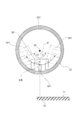
- FIG. 2 is a diagram for explaining the definition of the angle of the magnet that rotates and moves around the central axis of the rotary target.
- the rotary target 201 is illustrated among the plurality of rotary targets 201 to 210.
- the same definitions as those for the rotary target 201 are made for the rotary targets 202 to 210 other than the rotary target 201.
- the angle of the magnet 301 when the distance between the center of the magnet 301 and the substrate 10 is the shortest is set to 0 degrees.
- the position where the perpendicular line and the center 30 of the magnet 301 coincide with each other corresponds to an angle of 0 degrees of the magnet 301.
- the center 30 draws an arc trajectory.
- the angle is 0 degrees
- the magnet 310 is closest to the substrate 10, and the point on the arc at this time is defined as the point A.
- the clockwise direction is a positive angle (+ ⁇ ) and the counterclockwise direction is a negative angle ( ⁇ ) from 0 degrees.
- the position of the magnet 301 is assumed to be the angular position of the center 30 at a certain angle.
- the magnet 301 By rotating the magnet 301 around the central axis 20 of the rotary target 201, plasma can be concentrated near the target surface 21 on which the magnet 301 faces during magnetron discharge. In other words, the sputtered particles can be preferentially emitted from the target surface 21 on which the magnet 301 faces. Thereby, the direction in which the sputtering particles are emitted from the target surface 21 can be controlled according to the angle of the magnet 301. Further, after the substrate 10 is arranged to face the plurality of rotary targets 201 to 210, the direction of the sputtering particles toward the substrate 10 can be changed ex post facto by changing the range of the moving angle of the magnet 310.
- FIGS. 3 (a) and 3 (b) are graphs showing an example of the moving speed (angular velocity) of the magnet with respect to the angle of the magnet.
- FIG. 3A shows an example of the moving speed of the magnet with respect to the angle of the magnet 301.
- FIG. 3B shows an example of the moving speed of the magnet with respect to the angle of the magnet 310.
- the rotational movement of the magnets 301 and 310 exemplified in FIGS. 3A and 3B is one rotational movement from the start point to the end point.
- sputtering film formation is performed while rotating the magnets 301 and 310 in the clockwise direction.
- the magnets 301 and 310 of the pair of rotary targets 201 and 210 arranged at both ends among the plurality of rotary targets 201 to 210 are as follows. Controls rotational movement.
- the time required to form a film in a region farther from the center of the substrate 10 than the point A is longer than that of the point A.
- Rotate and move so that the time required to form a film is shorter in the region near the center.
- the rotary target 201 starts film formation from a region closer to the center of the substrate 10 than the point A on the arc
- the rotary target 210 starts film formation from a region farther from the center of the substrate 10 than the point A on the arc. Start.
- the magnet 301 rotates and moves in a range of an angle of ⁇ 60 degrees to +60 degrees.
- the position at an angle of ⁇ 60 degrees is the start point of the rotational movement of the magnet 301
- the position at the angle of +60 degrees is the end point of the rotational movement of the magnet 301.
- the angular velocity at the starting point position is approximately 0.2 deg. Whereas / sec, the angular velocity at the end point is 120 deg. Set to / sec.
- the angular velocity in the range from the starting point position to 25 degrees is 0.2 deg. / Sec to 0.2 deg. While it is around / sec, the angular velocity in the range from 25 degrees to the end point position is 120 deg. Set to / sec.
- the average angular velocity of moving in a region farther from the center of the substrate 10 than the point A on the arc is higher than the average angular velocity of moving in a region closer to the center of the substrate 10 than the point A. Rotate and move to make it faster.
- the average value of the angular velocities is low, whereas the magnet 301 has the point A.
- the average value of the angular velocity is set to high velocity.
- the magnet 310 rotates and moves in the range of an angle of -60 degrees to 60 degrees.
- the position at an angle of ⁇ 60 degrees is the start point of the rotational movement of the magnet 310
- the position at the angle of +60 degrees is the end point of the rotational movement of the magnet 310.
- the angular velocity of the magnet 310 at the starting point position is 120 deg.
- the angular velocity of the magnet 310 at the end point is approximately 0.2 deg. Set to / sec.
- the angular velocity in the range from the starting point position to -25 degrees is 120 deg.
- the angular velocity in the range from -25 degrees to the end point position is 0.2 deg. / Sec to 0.2 deg. It is set near / sec.
- the average angular velocity of moving in a region farther from the center of the substrate 10 than the point A on the arc is higher than the average angular velocity of moving in a region closer to the center of the substrate 10 than the point A. Rotate and move to make it faster.
- the average value of the angular velocities is high, whereas in the range in which the magnet 310 rotates from the position of point A to the end point position. Is set to a low average angular velocity.
- the change in the angular velocity with respect to the angle of the magnet 301 of the rotary target 201 (FIG. 3 (a)) and the change of the angular velocity with respect to the angle of the magnet 310 of the rotary target 210 (FIG. 3 (b)) cause the magnet to rotate and move.
- the angular velocities of the magnets 301 and 310 are set so as to be symmetrical in the range (-60 degrees to +60 degrees).
- the magnet 301 of the rotary target 201 and the magnet 310 of the rotary target 210 rotate and move in the same rotation direction.
- the direction of rotation is not limited to this example, and the directions in which the magnets 301 and 310 rotate and move may be opposite to each other.
- FIG. 4 (a) and 4 (b) are graphs showing an example of the ratio of the discharge time to the angle of the magnet.
- FIG. 4A shows an example of the ratio of the discharge time to the angle of the magnet 301
- FIG. 4B shows an example of the ratio of the discharge time to the angle of the magnet 310.
- the ratio of the discharge time corresponds to the ratio of the residence time of the magnet at the position of a predetermined angle. That is, the higher the ratio of the discharge time, the longer the movement time of the magnet at the angle position.
- the ratio of the discharge time corresponds to the ratio of the residence time of the discharge plasma concentrated in the vicinity of the target surface 21 facing the magnet, and the higher the ratio of the discharge time, the more the sputtering particles are emitted from the target surface 21. The amount will increase.
- the discharge time ratio at any position from -60 degrees to +25 degrees is in the range of 3% to 10%, whereas it is +25 degrees.
- the discharge time ratio at any position from to +60 degrees is controlled to approximately 0%.
- the discharge is longer when the magnet 301 is located from -60 degrees to +25 degrees than when the magnet 301 is located from +25 degrees to +60 degrees.
- Plasma stays.
- the sputtering particles emitted from the target surface 21 of the rotary target 201 are preferentially directed to the region from the end portion 12a toward the inside of the substrate 10 rather than the outside of the end portion 12a of the substrate 10.
- the discharge time ratio at any position from -60 degrees to -25 degrees is approximately 0% due to the rotational movement of the magnet 310, whereas- The discharge time ratio at any position from 25 degrees to +60 degrees is controlled in the range of 3% to 10%.
- the time when the magnet 310 is located from -25 degrees to +60 degrees is longer than when the magnet 310 is located from -60 to -25 degrees.
- the discharge plasma stays.
- the sputtering particles emitted from the target surface 21 of the rotary target 210 are preferentially directed to the region from the end portion 12b toward the inside of the substrate 10 rather than the outside of the end portion 12b of the substrate 10.
- FIGS. 3 (a) and 3 (b) and FIGS. 4 (a) and 4 (b) are examples, and the rotation angle at which each of the magnets 301 and 310 rotates is shown in FIG. 3 (a). ), (B) and FIGS. 4 (a) and 4 (b).
- the magnets 301, 310 of a pair of rotary targets 201, 210 are positioned at any angle in the range 20 to 90 degrees and at any angle in the range -20 to -90 degrees. It may rotate to and from the position of.
- the start point of the rotational movement of the magnet 301 of the rotary target 201 is a position at any angle in the range of -20 degrees to -90 degrees, and the end point of the rotational movement is any of the ranges of +20 degrees to +90 degrees.
- the start point of the rotational movement of the magnet 310 of the rotary target 210 is the position at any angle in the range of -20 degrees to -90 degrees, and the end point of the rotational movement is +20.
- the position may be at any angle in the range from degrees to +90 degrees.
- FIG. 5A is a graph showing an example of the moving speed (angular velocity) of the magnet with respect to the angle of the magnet.
- FIG. 5B is a graph showing an example of the ratio of the discharge time to the angle of the magnet.
- FIG. 5A shows an example of the moving speed of the magnet with respect to the angle of the magnets 302 to 309
- FIG. 5B shows an example of the ratio of the discharge time to the angle of the magnets 302 to 309. There is.
- the rotational movement is controlled so that the appearance is different from the rotational movement of the magnets 301 and 310.
- the magnets 302 to 309 rotate so that the angular velocity in the middle of the rotational movement becomes the fastest in the range of the rotation angle in which the magnets 302 to 309 rotate.
- the angular velocities of the magnets 302 to 309 have the highest angular velocities near the angle of 0 degrees (point A).
- the position at an angle of ⁇ 60 degrees is the start point of the rotational movement of the magnets 302 to 309
- the position at the angle of +60 degrees is the end point of the rotational movement of the magnets 302 to 309.
- the angular velocities at the start and end points of the magnets 302 to 309 are set lower than the angular velocities at the end points of the magnet 301 and the angular velocities at the start point of the magnet 310.
- the angular velocity is relatively slow near the start point, the angular velocity is relatively high in the middle of the rotational movement range, for example, at 0 degrees (point A), and the angular velocity is relatively slow again near the end point. Is controlled.
- Each magnet of the rotary targets 202 to 209 rotates and moves in the same rotation direction, for example.
- the discharge time ratio near the angle of 0 degrees is close to 0%, while the discharge time near the start point and the end point is near.
- the ratio is controlled higher than the discharge time ratio near 0 degrees.
- the discharge plasma is longer when the magnets 302 to 309 are located near the start point and the end point than when the respective angles of the magnets 302 to 309 are located near 0 degrees.
- the sputtering particles emitted from the target surface 21 of the rotary targets 202 to 209 are directed to a wide angle in the range from the start point to the end point.
- the sputtering particles emitted from each of the rotary targets 202 to 209 overlap on the substrate 10, and a film having a substantially uniform thickness is formed in the central portion of the substrate 10 on which the rotary targets 202 to 209 face each other. Will be done.
- FIGS. 5 (a) and 5 (b) The example shown in FIGS. 5 (a) and 5 (b) is an example, and the angle of rotation in which each of the magnets 302 to 309 rotates is not limited to the example in FIGS. 5 (a) and 5 (b). ..
- the change in the angular velocity with respect to each angle may be controlled to be symmetrical within the range in which the magnet rotates and moves.
- the magnet 302 of the rotary target 202 and the magnet 309 of the rotary target 209 may be controlled so that the change in the angular velocity with respect to each angle is symmetrical within the range in which the magnet rotates and moves.
- the magnet 303 of the rotary target 203 and the magnet 308 of the rotary target 208 may be controlled so that the change in the angular velocity with respect to each angle is symmetrical within the range in which the magnet rotates and moves.
- the magnet 304 of the rotary target 204 and the magnet 307 of the rotary target 207 may be controlled so that the change in the angular velocity with respect to each angle is symmetrical within the range in which the magnet rotates and moves.
- the magnet 305 of the rotary target 205 and the magnet 306 of the rotary target 206 may be controlled so that the change in the angular velocity with respect to each angle is symmetrical within the range in which the magnet rotates and moves.
- the magnets do not approach or face each other between adjacent rotary targets in order to ensure the stability of magnetron discharge. Therefore, it is desirable that the magnets of the plurality of rotary targets 201 to 210 rotate and move in the same rotation direction during the film formation.
- the thickness of the film formed near the end portions 12a and 12b of the substrate 10 is corrected, and the thickness of the film formed in the central portion of the substrate 10 and the end portion 12a of the substrate 10 are corrected.
- the thickness of the film formed in the vicinity of 12b is adjusted to be substantially uniform.
- FIG. 6 is a schematic plan view showing an example of the film forming apparatus of the present embodiment.
- FIG. 6 schematically shows a plan view of the film forming apparatus 400 when viewed from above. At least three or more rotary targets are arranged in the film forming apparatus 400.
- the film forming apparatus 400 As the film forming apparatus 400, a magnetron sputtering film forming apparatus is exemplified.
- the film forming apparatus 400 includes a vacuum vessel 401, a plurality of rotary targets 201 to 210, a power supply 403, a substrate holder 404, a pressure gauge 405, a gas supply system 406, a gas flow meter 407, and an exhaust system 408.
- the control device 410 is provided.
- the substrate 10 is supported by the substrate holder 404.
- the vacuum container 401 maintains a decompressed atmosphere by the exhaust system 408.
- the vacuum vessel 401 accommodates a plurality of rotary targets 201 to 210, a substrate holder 404, a substrate 10, and the like.
- a pressure gauge 405 for measuring the pressure inside the vacuum container 401 is attached to the vacuum container 401.
- a gas supply system 406 for supplying a discharge gas (for example, Ar, oxygen) is attached to the vacuum container 401.
- the gas flow rate supplied into the vacuum vessel 401 is adjusted by the gas flow meter 407.
- the plurality of rotary targets 201 to 210 are film forming sources of the film forming apparatus 400. For example, when a plurality of rotary targets 201 to 210 are sputtered by plasma formed in the vacuum vessel 401, the sputtering particles are emitted from the plurality of rotary targets 201 to 210 toward the substrate 10.
- the power supply 403 controls the discharge power applied to each of the plurality of rotary targets 201 to 210.
- the power supply 403 may be a DC power supply or a high frequency power supply such as RF or VHF.
- RF or VHF high frequency power supply
- the control device 410 controls the electric power output by the power supply 403, the opening degree of the gas flow meter 407, and the like.
- the pressure measured by the pressure gauge 405 is sent to the control device 410.
- the control device 410 controls to perform sputtering film formation on the substrate 10 while rotating and moving the magnets of the plurality of rotary targets 201 to 210 around the central axis 20.
- the control device 410 controls the rotational movement of the magnets 301 to 310 and controls the power supply to each of the plurality of rotary targets 201 to 210, which are described with reference to FIGS. 1 (a) to 5 (b). do.
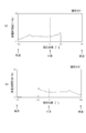
- FIG. 7A is a graph showing the film thickness distribution in the substrate surface according to the comparative example.
- FIG. 7B is a graph showing an example of the film thickness distribution in the substrate surface when the film is formed by the film forming method of the present embodiment.
- the broken line indicates the film thickness distribution when the sputtering particles emitted from the individual rotary targets 201 to 210 are deposited on the substrate 10.
- the solid line shows the film thickness distribution in which the film thickness distributions formed by the individual rotary targets 201 to 210 are combined.
- the width direction of the horizontal axis corresponds to the direction in which a plurality of rotary targets 201 to 210 are arranged side by side.
- the vertical axis is the film thickness.
- the film thickness distribution when the positions of the magnets 301 to 310 of the individual rotary targets 201 to 210 are fixed at 0 degrees is shown.
- the emission angle distribution of the sputtering particles emitted from the individual rotary targets 201 to 210 follows the so-called cosine law.
- the film thickness distribution by the individual rotary targets 201 to 210 shows a distribution symmetrical with respect to the center line of the film thickness distribution (broken line).
- the individual film thickness distributions show the same distribution.
- the emission angle distribution of the sputtering particles emitted from the rotary targets 201 and 210 is closer to the center side of the substrate 10 than in the comparative example, and the emission angle of the sputtering particles is set. Oriented to the center side of the substrate 10.
- the film thickness distribution by the rotary targets 201 and 210 becomes asymmetric with respect to the center line of the film thickness distribution, and the distribution is closer to the center side of the substrate 10.
- the peak of the film thickness distribution by the rotary targets 201 and 210 is higher than the peak of the film thickness distribution by the rotary targets 202 to 209.
- the emission angle distribution of the sputtering particles emitted from the rotary targets 201 and 210 is directed to a wider angle than in the comparative example.
- the film thickness distribution by the rotary targets 202 to 209 shows an appearance of spreading toward both ends of the substrate 10 as compared with the comparative example.
- the film thickness distribution (solid line) in which these individual film thickness distributions are overlapped becomes flatter than that in the comparative example, and the in-plane distribution of the film thickness becomes more uniform.
Abstract
Description
上記複数のロータリターゲットは、上記中心軸が互いに平行で、かつ上記中心軸が上記基板と平行になるように配置される。
上記複数のロータリターゲットに電力を投入しながら、上記複数のロータリターゲットのそれぞれの上記磁石を、上記中心軸の周りに、上記基板に最も近いA点を有する円弧上を移動させながら、上記基板にスパッタリング成膜を行い、上記複数のロータリターゲットの内、少なくとも両端に配置された一対のロータリターゲットの上記磁石は、上記円弧上において、上記A点より上記基板の中心から離れた領域で成膜する時間が上記A点より上記基板の中心に近い領域で成膜する時間より短い。 In order to achieve the above object, in the film forming method according to one embodiment of the present invention, at least a plurality of rotary targets having a central axis and a target surface and having a rotatable magnet inside the central axis are provided. Sputtering film formation is performed on the substrate using three or more.
The plurality of rotary targets are arranged so that the central axes are parallel to each other and the central axes are parallel to the substrate.
While applying power to the plurality of rotary targets, the magnets of each of the plurality of rotary targets are moved around the central axis on an arc having the point A closest to the substrate to the substrate. Sputter film formation is performed, and among the plurality of rotary targets, the magnets of the pair of rotary targets arranged at at least both ends form a film on the arc in a region away from the center of the substrate from the point A. The time is shorter than the time for forming a film in the region closer to the center of the substrate than the point A.
11…成膜面
12a、12b…端部
20…中心軸
21…ターゲット面
201~210…ロータリターゲット
301~310…磁石
400…成膜装置
401…真空容器
403…電源
404…基板ホルダ
405…圧力計
406…ガス供給系
407…ガス流量計
408…排気系
410…制御装置 10 ...
Claims (4)
- 中心軸とターゲット面とを有し、前記中心軸の周りに回転可能な磁石を内部に備えた複数のロータリターゲットを少なくとも3個以上用いて基板にスパッタリング成膜を行う成膜方法であって、
前記複数のロータリターゲットは、前記中心軸が互いに平行で、かつ前記中心軸が前記基板と平行になるように配置され、
前記複数のロータリターゲットに電力を投入しながら、前記複数のロータリターゲットのそれぞれの前記磁石を、前記中心軸の周りに、前記基板に最も近いA点を有する円弧上を移動させながら、前記基板にスパッタリング成膜を行い、
前記複数のロータリターゲットの内、少なくとも両端に配置された一対のロータリターゲットの前記磁石は、前記円弧上において、前記A点より前記基板の中心から離れた領域で成膜する時間が前記A点より前記基板の中心に近い領域で成膜する時間より短い
成膜方法。 A film forming method for forming a sputtering film on a substrate by using at least three rotary targets having a central axis and a target surface and having a magnet that can rotate around the central axis inside.
The plurality of rotary targets are arranged so that the central axes are parallel to each other and the central axes are parallel to the substrate.
While applying power to the plurality of rotary targets, the magnets of the plurality of rotary targets are moved around the central axis on an arc having the point A closest to the substrate, and the magnets are moved to the substrate. Sputter film formation,
Among the plurality of rotary targets, the magnets of the pair of rotary targets arranged at least at both ends have a time of forming a film on the arc in a region away from the center of the substrate from the point A from the point A. A film forming method shorter than the time required to form a film in a region close to the center of the substrate. - 請求項1に記載された成膜方法においては、
前記A点の前記磁石の角度を0度とし、前記0度から反時計回り方向を負角度、時計回り方向を正角度とした場合、
前記一対のロータリターゲットの前記磁石は、20度から90度までの範囲のいずれかの角度での位置と、-20度から-90度までの範囲のいずれかの角度での位置との間において回転移動する
成膜方法。 In the film forming method according to claim 1,
When the angle of the magnet at point A is 0 degree, the counterclockwise direction is a negative angle, and the clockwise direction is a positive angle from the 0 degree.
The magnets of the pair of rotary targets are located between a position at any angle in the range of 20 degrees to 90 degrees and a position at any angle in the range of -20 degrees to -90 degrees. A film formation method that moves in rotation. - 請求項1または2に記載された成膜方法においては、
前記両端に配置された一対のロータリターゲットの一方は、前記円弧上の前記A点より前記基板の中心に近い領域から成膜を開始し、
前記両端に配置された一対のロータリターゲットの他方は、前記円弧上の前記A点より前記基板の中心から離れた領域から成膜を開始する
成膜方法。 In the film forming method according to claim 1 or 2, the film forming method is used.
One of the pair of rotary targets arranged at both ends starts film formation from a region closer to the center of the substrate than the point A on the arc.
A film forming method in which the other of the pair of rotary targets arranged at both ends starts film formation from a region away from the center of the substrate from the point A on the arc. - 請求項1~3のいずれか1つに記載された成膜方法においては、
前記両端に配置された一対のロータリターゲットの前記磁石の移動において、前記円弧上の前記A点より前記基板の中心から離れた領域を移動する平均の角速度が前記A点より前記基板の中心に近い領域を移動する平均の角速度より速い
成膜方法。 In the film forming method according to any one of claims 1 to 3, the film forming method is used.
In the movement of the magnets of the pair of rotary targets arranged at both ends, the average angular velocity of moving in a region away from the center of the substrate from the point A on the arc is closer to the center of the substrate than the point A. A film formation method that is faster than the average angular velocity of moving regions.
Priority Applications (3)
| Application Number | Priority Date | Filing Date | Title |
|---|---|---|---|
| CN202180009850.6A CN114981470A (en) | 2020-07-08 | 2021-03-22 | Film forming method |
| JP2022534907A JP7358647B2 (en) | 2020-07-08 | 2021-03-22 | Film forming method |
| KR1020227022033A KR20220106187A (en) | 2020-07-08 | 2021-03-22 | film formation method |
Applications Claiming Priority (2)
| Application Number | Priority Date | Filing Date | Title |
|---|---|---|---|
| JP2020-117530 | 2020-07-08 | ||
| JP2020117530 | 2020-07-08 |
Publications (1)
| Publication Number | Publication Date |
|---|---|
| WO2022009484A1 true WO2022009484A1 (en) | 2022-01-13 |
Family
ID=79552859
Family Applications (1)
| Application Number | Title | Priority Date | Filing Date |
|---|---|---|---|
| PCT/JP2021/011719 WO2022009484A1 (en) | 2020-07-08 | 2021-03-22 | Film forming method |
Country Status (5)
| Country | Link |
|---|---|
| JP (1) | JP7358647B2 (en) |
| KR (1) | KR20220106187A (en) |
| CN (1) | CN114981470A (en) |
| TW (1) | TWI821656B (en) |
| WO (1) | WO2022009484A1 (en) |
Citations (3)
| Publication number | Priority date | Publication date | Assignee | Title |
|---|---|---|---|---|
| JP2005350768A (en) * | 2004-05-05 | 2005-12-22 | Applied Films Gmbh & Co Kg | Coater with large area assembly of rotatable magnetron |
| JP2013506756A (en) * | 2009-10-02 | 2013-02-28 | アプライド マテリアルズ インコーポレイテッド | Method and coater for coating a substrate |
| JP2019519673A (en) * | 2016-04-21 | 2019-07-11 | アプライド マテリアルズ インコーポレイテッドApplied Materials,Incorporated | Method for coating a substrate, and coater |
Family Cites Families (5)
| Publication number | Priority date | Publication date | Assignee | Title |
|---|---|---|---|---|
| JPH0688217A (en) * | 1992-09-09 | 1994-03-29 | Hitachi Ltd | Method and device for simultaneous formation of film by sputtering on both surfaces |
| JP5104151B2 (en) * | 2007-09-18 | 2012-12-19 | 東京エレクトロン株式会社 | Vaporization apparatus, film forming apparatus, film forming method, and storage medium |
| WO2015072046A1 (en) * | 2013-11-14 | 2015-05-21 | 株式会社Joled | Sputtering apparatus |
| JP6498819B1 (en) * | 2018-05-10 | 2019-04-10 | 京浜ラムテック株式会社 | Sputtering cathode assembly and sputtering apparatus |
| WO2021180396A1 (en) * | 2020-03-13 | 2021-09-16 | Evatec Ag | Apparatus and process with a dc-pulsed cathode array |
-
2021
- 2021-03-22 JP JP2022534907A patent/JP7358647B2/en active Active
- 2021-03-22 KR KR1020227022033A patent/KR20220106187A/en active Search and Examination
- 2021-03-22 WO PCT/JP2021/011719 patent/WO2022009484A1/en active Application Filing
- 2021-03-22 CN CN202180009850.6A patent/CN114981470A/en active Pending
- 2021-04-28 TW TW110115217A patent/TWI821656B/en active
Patent Citations (3)
| Publication number | Priority date | Publication date | Assignee | Title |
|---|---|---|---|---|
| JP2005350768A (en) * | 2004-05-05 | 2005-12-22 | Applied Films Gmbh & Co Kg | Coater with large area assembly of rotatable magnetron |
| JP2013506756A (en) * | 2009-10-02 | 2013-02-28 | アプライド マテリアルズ インコーポレイテッド | Method and coater for coating a substrate |
| JP2019519673A (en) * | 2016-04-21 | 2019-07-11 | アプライド マテリアルズ インコーポレイテッドApplied Materials,Incorporated | Method for coating a substrate, and coater |
Also Published As
| Publication number | Publication date |
|---|---|
| TWI821656B (en) | 2023-11-11 |
| CN114981470A (en) | 2022-08-30 |
| JP7358647B2 (en) | 2023-10-10 |
| JPWO2022009484A1 (en) | 2022-01-13 |
| KR20220106187A (en) | 2022-07-28 |
| TW202202644A (en) | 2022-01-16 |
Similar Documents
| Publication | Publication Date | Title |
|---|---|---|
| WO2010073307A1 (en) | Sputtering system and film deposition method | |
| JP6963551B2 (en) | Vacuum processing equipment and methods for processing substrates | |
| KR20170131816A (en) | Film forming apparatus and method for manufacturing a work film is formed | |
| US20120006266A1 (en) | Sputtering apparatus, method of operating the same, and method of manufacturing substrate using the same | |
| JP2000265263A (en) | Method and device for sputtering | |
| JP2012241281A (en) | Split target device for sputtering and sputtering method using the same | |
| TWI776802B (en) | Magnetic film deposition apparatus and magnetic film deposition method | |
| TWI386504B (en) | Film forming apparatus and film forming method | |
| WO2022009484A1 (en) | Film forming method | |
| WO2015072046A1 (en) | Sputtering apparatus | |
| US9426875B2 (en) | Method for producing plasma flow, method for plasma processing, apparatus for producing plasma, and apparatus for plasma processing | |
| JP7097172B2 (en) | Sputtering equipment | |
| JP4246546B2 (en) | Sputtering source, sputtering apparatus, and sputtering method | |
| JP4740300B2 (en) | Sputtering method and apparatus, and electronic component manufacturing method | |
| JP4974582B2 (en) | Deposition equipment | |
| US9449800B2 (en) | Sputtering apparatus and sputtering method | |
| US8852412B2 (en) | Magnetron source and method of manufacturing | |
| KR100270457B1 (en) | Sputtering apparatus | |
| TW202012672A (en) | Film formation apparatus | |
| JP2001020067A (en) | Sputtering method and device | |
| JPH01268867A (en) | Magnetron sputtering device | |
| US6488821B2 (en) | System and method for performing sputter deposition using a divergent ion beam source and a rotating substrate | |
| JP6947569B2 (en) | Sputtering equipment | |
| JP2001262337A (en) | Magnetron sputtering system | |
| JP2005171369A (en) | Substrate holding mechanism |
Legal Events
| Date | Code | Title | Description |
|---|---|---|---|
| 121 | Ep: the epo has been informed by wipo that ep was designated in this application |
Ref document number: 21837466 Country of ref document: EP Kind code of ref document: A1 |
|
| ENP | Entry into the national phase |
Ref document number: 20227022033 Country of ref document: KR Kind code of ref document: A |
|
| ENP | Entry into the national phase |
Ref document number: 2022534907 Country of ref document: JP Kind code of ref document: A |
|
| NENP | Non-entry into the national phase |
Ref country code: DE |
|
| 122 | Ep: pct application non-entry in european phase |
Ref document number: 21837466 Country of ref document: EP Kind code of ref document: A1 |