WO2022009304A1 - プログラム作成支援装置 - Google Patents
プログラム作成支援装置 Download PDFInfo
- Publication number
- WO2022009304A1 WO2022009304A1 PCT/JP2020/026549 JP2020026549W WO2022009304A1 WO 2022009304 A1 WO2022009304 A1 WO 2022009304A1 JP 2020026549 W JP2020026549 W JP 2020026549W WO 2022009304 A1 WO2022009304 A1 WO 2022009304A1
- Authority
- WO
- WIPO (PCT)
- Prior art keywords
- program
- communication
- time
- processing
- estimated
- Prior art date
- Legal status (The legal status is an assumption and is not a legal conclusion. Google has not performed a legal analysis and makes no representation as to the accuracy of the status listed.)
- Ceased
Links
Images








Classifications
-
- G—PHYSICS
- G06—COMPUTING OR CALCULATING; COUNTING
- G06F—ELECTRIC DIGITAL DATA PROCESSING
- G06F8/00—Arrangements for software engineering
- G06F8/30—Creation or generation of source code
- G06F8/34—Graphical or visual programming
Definitions
- This disclosure relates to a program creation support device that supports the development of a program executed by a parallel real-time processing device.
- Patent Document 1 Conventionally, as a program creation support device for developing a program executed by a parallel real-time processing device, for example, there is a program development device disclosed in Patent Document 1.
- This program development device has an input device for selecting icons for creating a diagram, a display device for displaying a diagram being created or created, a diagram creation unit for creating a diagram, and a diagram creation device. It is equipped with an icon storage unit that stores the program entity corresponding to the icon used in. Further, the program development device includes a diagram storage unit for storing a created diagram, an interpreter for interpreting and executing the created diagram, and an object library composed of a plurality of objects.
- the conventional program creation support device represented by the program development device disclosed in Patent Document 1 cannot describe the HW (hardware) and SW (software) configurations of the system that executes the parallel real-time processing device. Therefore, when executing a process on a computer composed of a plurality of CPUs (Central Processing Units) and an OS (Operating System), it is necessary to separately design the CPU and the OS that execute each process, which is troublesome. Was occurring.
- CPUs Central Processing Units
- OS Operating System
- the program creation support device is a program creation support device for a parallel real-time processing device, and includes an input device for imparting program environment information including the configurations of the CPU and OS used by the parallel real-time processing device, and the above-mentioned.
- a program creation unit that creates a program using the CPU and OS specified by the program environment information and outputs program information indicating the contents of the program, receives the program information, and obtains an estimated program execution time for the program.
- the program creation unit includes an execution time estimation unit that executes execution time estimation processing, associates a plurality of processes constituting the program with a plurality of icons, and designates a CPU and an OS for each of the plurality of icons.
- a process that describes the execution order relationship between the plurality of icons The process configuration description unit that executes the process configuration description process and the communication content description process that describes the communication content of each of the required number of communication paths between the plurality of icons are executed.
- the execution time estimation unit estimates the processing time of the associated processing for each of the plurality of icons based on the designated CPU and OS, and obtains the estimated processing time.
- the processing time estimation unit that executes the processing time estimation process and the communication time estimation process that estimates the communication time and obtains the estimated communication time based on the designated CPU and OS are executed for each of the required number of communication paths.
- the processing configuration description process and the communication content description process are executed in conjunction with a user operation using the input device, and the execution of the processing time estimation process and the communication time estimation process is started.
- the instruction is given by a user operation using the input device, the execution time estimation process includes the processing time estimation process and the communication time estimation process, and the estimation program execution time is the estimation process of each of the plurality of icons.
- the program creation support device includes the estimated communication time for each of the time and the required number of communication paths, associates the estimated processing time with each of the plurality of icons, and estimates the estimated communication path for each of the required number of communication paths. It is further equipped with a display device that displays program information with an estimated time associated with communication time on the screen.
- the program creation support device of the present disclosure causes the processing time estimation unit and the communication time estimation unit to execute the processing time estimation processing and the communication time estimation processing, so that the estimation processing of each of the plurality of icons is estimated based on the designated CPU and OS.
- the time and the estimated communication time of each of the required number of communication paths can be obtained as the estimated program execution time.
- the user appropriately changes the association of the CPU and the OS with the plurality of icons and refers to the program information with the estimated time displayed on the screen of the display device, which adversely affects the total execution time of the program. Factors can be recognized relatively easily.
- the program creation support device of the present disclosure can effectively support the creation of a program to be executed within the time desired by the user.
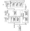
- FIG. It is a block diagram which shows the structure of the program creation support apparatus which is Embodiment 1.
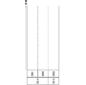
- FIG. It is explanatory drawing which shows the concept of the chart (initial state) created by the chart making part shown in FIG.
- It is explanatory drawing which shows the image of a single icon.
- It is explanatory drawing which shows the image of the communication path between icons.
- It is explanatory drawing which shows the image of the communication path displayed in a separate window.
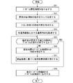
- It is a flowchart which shows the processing procedure of the program creation process using the program creation support apparatus of Embodiment 1.
- FIG. It is a block diagram which shows the structure of the program creation support apparatus which is Embodiment 2.
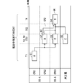
- FIG. 1 It is explanatory drawing which shows typically the example of the chart created by the chart making part shown in FIG. It is a flowchart which shows the execution procedure of the internal processing by the program creation auxiliary part shown in FIG. It is a flowchart which shows the processing procedure of the program creation process using the program creation support apparatus of Embodiment 2. It is a block diagram which shows the structure of the program creation support apparatus which is Embodiment 3.
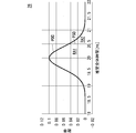
- FIG. It is explanatory drawing which shows an example of the estimation result of the estimation processing time with a probability distribution in a graph format. It is explanatory drawing which shows an example of the estimation result of the estimation processing time with a probability distribution in a table format. It is explanatory drawing which shows an example of the analysis content of the estimation processing time with probability distribution shown in FIG.
- FIG. 1 is a block diagram showing a configuration of a program creation support device 71 according to the first embodiment of the present disclosure.
- the program creation support device 71 includes a program creation unit 1, an execution time estimation unit 2, a program conversion unit 3, an input device 4, and a display device 5 as main components.
- the input device 4 receives the program environment information D4 including the configuration of the CPU and the OS used by the parallel real-time processing device from the outside, and assigns the program environment information D4 to the program creation unit 1.
- the program environment information D4 usually indicates a plurality of CPUs and a plurality of OSs. However, one of the CPU and the OS may be one of the instruction contents of the program environment information D4.
- the program creation unit 1 creates a program using the CPU and OS specified by the program environment information D4. Then, the program creation unit 1 outputs the program information D6 indicating the contents of the created program to the execution time estimation unit 2, the program conversion unit 3, and the display device 5.
- the parallel real-time processing device that actually executes the program created by the program creation unit 1 may be referred to as a “development target HW”.
- the execution time estimation unit 2 receives the program information D6 and executes the execution time estimation process for obtaining the estimated program execution time for the program.
- the program creation unit 1 includes the chart creation unit 11 and the processing content creation unit 12 as main components.
- the chart creation unit 11 describes the structure of the program to be created by connecting the icons and the icons to each other. That is, the chart creation unit 11 associates a plurality of processes constituting the program with a plurality of icons. Further, the chart creation unit 11 includes a processing configuration description unit 111 and a communication content description unit 112 as main components.
- the processing configuration description unit 111 recognizes the CPU and OS information used by the development target HW from the program environment information D4.
- the process configuration description unit 111 associates a plurality of processes constituting the program with a plurality of icons, specifies a CPU and an OS for each of the plurality of icons, and describes an execution order relationship between the plurality of icons. Execute the process.
- the "icon” used in the present specification means a program component corresponding to "processing”. Further, as a program component, a program module, a function constituting the program, a group of functions, and the like can be considered.
- the communication content description unit 112 executes a communication content description process for describing the communication content of each of the required number of communication paths between the plurality of icons.
- the communication content includes the communication method to be used and the content of the data to be communicated.
- the process content creation unit 12 executes the process content creation process for creating the process content of each of the plurality of icons.
- the process configuration description process, the communication content description process, and the process content creation process are executed in conjunction with the user operation by the operator using the input device 4.
- the program creation unit 1 creates a program by executing the above-mentioned processing configuration description processing, the above-mentioned communication content description processing, and the above-mentioned processing content creation processing, and obtains program information D6 indicating the contents of the created program.
- the program information D6 is information that indicates a plurality of icons whose execution order is specified, a CPU and an OS designated for each of the plurality of icons, a required number of communication paths, and processing contents of the plurality of icons.
- the execution time estimation unit 2 includes the processing time estimation unit 21 and the communication time estimation unit 22 as main components.
- the processing time estimation unit 21 refers to the program information D6 and estimates the processing time of the associated processing for each of the plurality of icons instructed by the program information D6 based on the designated CPU and OS. Obtain the estimated processing time Execute the processing time estimation processing. Therefore, by executing the processing time estimation processing by the processing time estimation unit 21, it is possible to obtain a plurality of estimated processing times corresponding to the plurality of icons.
- the communication time estimation unit 22 executes a communication time estimation process for estimating the communication time and obtaining the estimated communication time for each of the required number of communication paths based on the designated CPU and OS. Therefore, by executing the communication time estimation process by the communication time estimation unit 22, the required number of estimated communication times corresponding to the required number of communication paths can be obtained.
- the estimated program execution time obtained by the execution time estimation unit 2 includes the estimated processing time of each of the plurality of icons and the estimated communication time of each of the required number of communication paths.
- the execution time estimation unit 2 executes the execution time estimation process including the processing time estimation process and the communication time estimation process, and the program information D6t with the estimated time in which the above-mentioned estimated program execution time is added to the program information D6. Can be obtained.
- program information D6 in which the above-mentioned estimated program execution time is added may be referred to as "program information D6t with estimated time".
- the program information D6t with an estimated time is information in which the estimated processing time is associated with each of the plurality of icons and the estimated communication time is associated with each of the required number of communication paths.
- the execution time estimation unit 2 obtains the estimated total execution time AT of the entire program from the plurality of estimated processing times and the required number of estimated communication times, and includes the estimated total execution time AT in the estimated program execution time.
- the instruction to start execution of each of the processing time estimation process and the communication time estimation process included in the execution time estimation process is given by a user operation using the input device 4.
- a program in which the correspondence between the CPU and the OS is confirmed by the program creation unit 1 is defined as a confirmed program, and among the program information D6, the information indicating the content of the confirmed program may be particularly referred to as "confirmed program information D6f".
- the confirmation program information D6f includes a plurality of icons, a required number of communication paths, a CPU and an OS for which designations for the plurality of icons have been confirmed, and processing contents of the plurality of icons.
- the program conversion unit 3 receives the finalized program information D6f, converts it into a dedicated program executed by the development target HW, and creates the dedicated program information D3 indicating the contents of the dedicated program.
- the program conversion unit 3 includes a processing code generation unit 31, a communication code generation unit 32, and a setting code generation unit 33 as main components.
- the processing code generation unit 31 converts the processing of the plurality of icons instructed by the confirmation program information D6f into a plurality of processing codes for the development target HW.
- the communication code generation unit 32 converts the required number of communication paths specified in the confirmation program information D6f into the required number of communication codes for the development target HW.
- the setting code generation unit 33 generates CPUs and OSs assigned to a plurality of icons as a plurality of OS / CPU codes for the development target HW based on the instruction content of the confirmation program information D6f.
- the dedicated program information D3 includes a plurality of processing codes for the development target HW, a required number of communication codes, and a plurality of OS / CPU codes.
- the input device 4 accepts a user operation which is an operation by an operator, and at least imparts program environment information D4 regarding the number of CPUs of the development target HW, the type of OS, and the performance value of each CPU to the program creation unit 1. It should be noted that all or part of the program environment information D4 may be taken in from the outside via the input device 4.
- program creation unit 1, the execution time estimation unit 2, and the program conversion unit 3 can be operated by a user operation using the input device 4.
- the display device 5 displays the contents of the program information D6 or the program information D6t with an estimated time on the screen in a manner that the operator can visually recognize.
- FIG. 18 is a block diagram schematically showing the hardware configuration of the program creation support device 71. As shown in the figure, a keyboard 101, a computer 102, a memory 103, and a display 104 are connected to a bus 105 that transmits and receives data.
- the computer 102 has a CPU (also referred to as a central processing unit, a central processing unit, a processing unit, an arithmetic unit, a microprocessor, a microcomputer, a processor, or a DSP) for executing a memory 103 or an application program stored therein. ..
- a CPU also referred to as a central processing unit, a central processing unit, a processing unit, an arithmetic unit, a microprocessor, a microcomputer, a processor, or a DSP
- the memory 103 for example, a non-volatile or volatile semiconductor memory such as RAM, ROM, flash memory, EPROM, EEPROM, etc. can be considered. Further, the memory 103 may be a magnetic disk, a flexible disk, an optical disk, a compact disk, a mini disk, a DVD, or the like, or any storage medium used in the future.
- a non-volatile or volatile semiconductor memory such as RAM, ROM, flash memory, EPROM, EEPROM, etc.
- the memory 103 may be a magnetic disk, a flexible disk, an optical disk, a compact disk, a mini disk, a DVD, or the like, or any storage medium used in the future.
- the program creation unit 1, the execution time estimation unit 2, and the program conversion unit 3 are all realized by the computer 102 executing the application program.
- the input device 4 corresponds to a keyboard 101 connected to a computer 102, and also includes a mouse (not shown in FIG. 18). Further, when at least a part of the program environment information D4 is taken in from the outside, an input port is included as the input device 4.
- the display device 5 corresponds to the display 104 connected to the computer 102 via the bus 105.
- the program information D6 is recorded in the memory 103 or the recording device in the computer 102.
- FIG. 2 is an explanatory diagram showing the concept of the chart (initial state) created by the chart creation unit 11.
- the chart creation unit 11 includes information on the CPU and OS for the development target HW assigned as program environment information D4 from the input device 4, and an area for allocating processing to each CPU and OS.
- a chart including a time axis for making the processing time and communication time intuitively understandable is displayed on the screen of the display device 5.
- processing configuration description unit 111 which is the main component of the chart creation unit 11, by arranging the icons in the areas corresponding to each CPU and OS, it is possible to select the CPU and OS to execute the processing corresponding to the icons. ..
- CPU1 and CPU2 are assigned to OS-A, and CPU3 is assigned to OS-B.
- the program environment information D4 indicates CPU1 to CPU3, OS-A, and OS-B as the configurations of the CPU and the OS.
- the execution order of the icons is determined. Furthermore, by adding a pin to the icon, it is possible to indicate that there is data output from the icon or input to the icon.
- FIG. 3 is an explanatory diagram showing an image of a single icon
- FIG. 4 is an explanatory diagram showing an image of a communication path between icons.
- the icon 50 is set corresponding to the process a.
- the icons 51 and 52 are set corresponding to the processes A and B.
- the pin 61 on the output side of the icon 51 and the pin 62 on the input side of the icon 52 are connected by the communication path CP1.
- the communication path CP1 indicates that communication processing is performed from the icon 51 to the icon 52.
- the communication content description unit 112 which is the main component of the chart creation unit 11, describes the communication content of the communication path CP between the icons created by the processing configuration description unit 111.
- the communication content describes the communication path CP in which the pins are connected on the chart in a separate window different from the chart.
- FIG. 5 is an explanatory diagram showing an image of a communication path displayed in a separate window. As shown in FIG. 5, the communication path CP from the "process A" instructed by the icon 51 to the "process B" instructed by the icon 52 is described.
- the variables a to c that are the output data are output from the pins 61a to 61c on the output side of the icon 51.
- the input side pins 62d to 62f of the icon 52 receive the variables d to f as input data.
- the variable a output from the icon 51 is input to the pin 62e as the variable e of the icon 52
- the variable b output from the icon 51 is input to the pin 62d as the variable d of the icon 52
- the variable c is input to the pin 62f as the variable f of the icon 52.
- FIG. 5 shows that a communication path CP for performing data communication between the variables a to c and the variables d to f is provided between the icons 51 and 52.
- the communication method to be adopted can be determined for each communication path CP.
- the communication method is such that the operator can intuitively recognize the communication method by displaying the name of the communication method in the vicinity of the line indicating the communication path CP. Further, the line type indicating the communication path CP may be displayed in different contents for each communication method.
- communication methods such as socket, shared memory, and pipe.
- the socket can communicate in both directions and is a more reliable communication method than the communication by the shared memory.
- Pipes can communicate in only one direction, but they are a simpler communication method than sockets.
- Communication using shared memory is a method in which data is stored in a memory that can be accessed by both the transmitting side and the receiving side, and the data is exchanged between the transmitting side and the receiving side.
- the communication method using shared memory is the fastest, but it has the disadvantage that reliability is lowered if the implementation is wrong, such as a fatal error if the access address is wrong.
- sockets and pipes are highly reliable, but their communication speed is slow. Therefore, which communication method is adopted among a plurality of communication methods including sockets, shared memory, and pipes is on a case-by-case basis.
- the program environment information D4 includes a plurality of communication methods to be selected.
- FIG. 6 is an explanatory diagram schematically showing an example of a chart (creation stage) created by the chart creation unit 11.
- four icons 51 to 54 are set corresponding to processes A to D.
- the icon 51 is assigned to the CPU 1
- the icon 52 is assigned to the CPU 2
- the icons 53 and 54 are assigned to the CPU 3.
- FIG. 6 it is shown that the icon 51, the icons 52 and 53, and the icon 54 are executed in this order between the icons 51 and 54.
- the icons 52 and 53 are parallel processes executed by the CPU 2 and the CPU 3.
- FIG. 6 shows that communication processing is performed between the icon 52 and the icon 54 via the communication path CP2.
- the processing content corresponding to each icon is created by the processing content creating unit 12.
- the processing content creation unit 12 may be in a chart format using the same icons as the chart creation unit 11 or in a format created by an external tool.
- the created processing content is managed in association with the icon.
- the program information D6 created by the program creation support device 71 is instructed of a plurality of icons, a required number of communication paths, processing contents of the plurality of icons, an OS and CPU corresponding to the plurality of icons, and an execution procedure of the plurality of icons. Contains information.
- the icons 51 to 54 correspond to a plurality of icons
- the communication path CP1 corresponds to a required number of communication paths.
- the arrow between the icons 51 to 54 indicates the execution procedure of the plurality of icons, and the OS and the CPU for executing each of the icons 51 to 54 are specified depending on the position where the icons 51 to 54 are arranged.
- the execution time estimation unit 2 receives the program information D6 created by the program creation unit 1 and executes an execution time estimation process for obtaining an estimated program execution time for the program instructed by the program information D6.
- the estimated program execution time includes the estimated processing time for each of the plurality of icons, the estimated communication time for each of the required number of communication paths, and the estimated total execution time AT.
- the generic name of the estimated processing time for each of the plurality of icons may be referred to as “plurality of estimated processing time”
- the generic term of the estimated communication time for each of the required number of communication paths may be referred to as “required number of estimated processing time”.
- the above-mentioned estimated total execution time AT can be obtained by arithmetic processing including addition based on a plurality of estimated processing times and a required number of estimated processing times.
- the execution time estimation unit 2 adds information indicating the estimated program execution time including the estimated total execution time AT, a plurality of estimated processing times, and the required number of estimated processing times to the program information D6 based on the program information D6.
- Program information D6t with estimated time can be obtained.
- the program information D6t with an estimated time is appropriately transmitted to the program creation unit 1 and the program conversion unit 3.
- the program information D6t with the estimated time is obtained by the execution time estimation unit 2
- the program information D6t with the estimated time can be given to the display device 5 via the program creation unit 1.
- the display device 5 displays the estimated processing times T1 to T4 corresponding to the icons 51 to 54, the estimated communication time TC2 corresponding to the communication path CP2, and the estimated total execution time AT along the time axis. Can be displayed on the screen of.
- the processing time estimation process by the processing time estimation unit 21 refers to the processing content of each icon, and is based on the number of steps required for processing and the performance of the CPU that executes the icon, and is simulated using a hardware simulator or in advance. It is executed as an arithmetic process based on the relationship between the number of evaluated steps and the execution speed.
- the processing content of each icon is created by the processing content creating unit 12.
- the communication time estimation process by the communication time estimation unit 22 is executed based on the variables that communicate on each communication path and the communication method. For example, the communication time estimation process can be executed by using the previously evaluated data amount and the relationship between the communication method and the communication time with respect to the selected communication method.
- the communication method and communication content of each communication path are created by the communication content description unit 112.
- Estimated total execution time AT starts from the start point icon at the left end of the chart, traces the connected icons in order, and traces to the end point icon at the right end, the estimated processing time of each icon and the communication time in each communication path CP. It becomes the sum of. However, when it is possible to trace from the start point icon to the end point icon by a plurality of routes, the worst value among the estimated execution times of the plurality of routes is set as the estimated total execution time AT.
- the definite program information D6f created by the program creation unit 1 and indicating the contents of the definite program for which the allocation of the OS and the CPU has been completed is given to the program conversion unit 3.
- the program conversion unit 3 converts the finalized program indicated by the finalized program information D6f into a dedicated program executed by the development target HW, and outputs the dedicated program information D3 instructing the dedicated program.
- the dedicated program information D3 includes a plurality of processing codes executed in the development target HW, a required number of communication codes, and a plurality of OS / CPU codes.
- FIG. 7 is a flowchart showing a processing procedure of the program creation process using the program creation support device 71 of the first embodiment.
- the program creation process is started when the program creation support device of the first embodiment is started.
- step S11 the operator assigns the program environment information D4 regarding the development target HW from the input device 4 to the program creation unit 1.
- the program environment information D4 includes the number of CPUs used by the development target HW, CPU performance, OS type, and the like.
- the program environment information D4 usually indicates a plurality of CPUs and a plurality of OSs.
- step S12 the process desired to be executed in the development target HW is described by the icon by the process configuration description process by the process configuration description unit 111.
- step S13 the process content is created for the icon described in step S12 by the process content creation process by the process content creation unit 12. It should be noted that the processing content may be created by using another external tool without using the processing content creating unit 12.
- step S14 the communication content in each communication path is described by the communication content description process by the communication content description unit 112.
- the information required for the program information D6 can be obtained by the above-mentioned steps S11 to S14.
- the processes of steps S11 to S14 are performed in conjunction with the user operation of the operator who is the user using the input device 4.
- step S15 it is confirmed whether the execution of the program instructed by the program information D6 is completed within the execution time requested by the operator.
- Step S15 is a confirmation process by the operator.
- step S15 will be described in detail.
- the execution time estimation unit 2 is made to execute the execution time estimation process, and the program information D6t with the estimated time is generated based on the program information D6.
- the program information D6t with estimated time is displayed on the screen of the display device 5 in a visually recognizable form.
- the operator can determine YES / NO in step S15 by recognizing the estimated total execution time AT with reference to the program information D6t with estimated time displayed on the screen of the display device 5.
- step S15 determines whether "RT ⁇ AT" is satisfied between the request total execution time RT and the estimated total execution time AT requested by the operator, the determination result in step S15 is YES, and if not satisfied, the determination result in step S15. Is NO.
- step S15 If the step S15 is YES, the current program information D6 is output to the program conversion unit 3 as the finalized program information D6f in the step S18.
- the dedicated program information D3 for the development target HW can be obtained by the program conversion process by the program conversion unit 3. After the execution of step S18, the process ends.
- step S15 the operator performs the program improvement processing of steps S16 and S17.
- step S16 the content of the program information D6t with an estimated time is verified.
- the program information D6t with an estimated time includes a plurality of estimated processing times and a required number of estimated communication times in addition to the estimated total execution time AT.
- the operator can select the icon or the communication path that adversely affects the estimated total execution time AT. Can be recognized.
- step S17 the operator executes the individual improvement process based on the verification result of step S16. for example.
- the icon that has an adverse effect the allocation of OS and CPU is changed, and the processing content is changed.
- the communication path that has an adverse effect the allocation of the OS and the CPU is changed, and the communication content is changed.
- the OS and CPU assignments to the icons can be changed relatively easily, which is an effective countermeasure for improving the processing time of each icon and the communication time of each communication path. This is because the processing time of the icon and the communication time of the communication path change depending on the assigned OS and CPU.
- step S15 After that, the process returns to step S15 again, and if YES in step S15, the process ends through step S18. On the other hand, if NO in step S15, the processes of steps S16 and S17 are performed again.
- the program creation support device 71 of the first embodiment can be used.
- the operator uses the program creation support device 71 to set the OS and CPU for executing each process constituting the program, while estimating the estimated total execution time AT, the estimated processing time of each icon, and the estimation of each communication path. It is possible to create a program considering the communication time.
- the program creation support device 71 of the first embodiment is designated by causing the processing time estimation unit 21 to execute the processing time estimation process and the communication time estimation unit 22 to execute the communication time estimation process. Based on the CPU and the OS, the estimated processing time of each of the plurality of icons and the estimated communication time of each of the required number of communication paths can be obtained.
- the operator who becomes the user estimates the program by appropriately changing the association of the CPU and the OS with the plurality of icons and referring to the program information D6t with the estimated time displayed on the screen of the display device 5.
- the factors that adversely affect the total execution time AT can be recognized relatively easily.
- step S17 for the icon or the communication path that adversely affects the estimated total execution time AT of the program.
- the program creation support device 71 of the first embodiment can effectively support the creation of a program to be executed within the entire request execution time RT desired by the operator.
- program creation support device 71 of the first embodiment can create the processing content of each of the plurality of icons by the processing content creating process by the processing content creating unit 12.
- the operator in addition to associating the CPU and the OS with the plurality of icons, the operator appropriately changes the processing contents of the plurality of icons and refers to the program information D6t with an estimated time displayed on the screen of the display device 5. be able to.
- the program creation support device 71 of the first embodiment can support the creation of a program to be executed within the entire request execution time RT desired by the operator in a wider range.
- the program creation support device 71 of the first embodiment has a program conversion unit 3. Therefore, it is possible to automatically obtain the dedicated program information D3 that indicates the dedicated program for the development target HW that operates within the entire request execution time RT desired by the operator.
- FIG. 8 is a block diagram showing the configuration of the program creation support device 72 according to the second embodiment of the present disclosure. As shown in FIG. 8, the program creation support device 72 of the second embodiment is characterized in that the program creation assisting unit 7 is added to the program creation support device 71 of the first embodiment.
- the input device 4 newly receives instruction information instructing the start of the allocation assist process by the program creation assist unit 7.
- the program environment information D4 given from the input device 4 is extended to the program environment information D4t with a requested time.
- the program environment information D4t with the required time includes the entire program request execution time RT, a plurality of request processing times corresponding to a plurality of processes, and the required number of requested communications corresponding to the required number of communication paths. Contains request execution time information that indicates the time.
- the hardware configuration of the second embodiment is also as shown in FIG. 18 as in the first embodiment.
- the newly added program creation assisting unit 7 is realized by the computer 102 executing the application program.
- FIG. 9 is an explanatory diagram schematically showing an example of a chart created by the chart creation unit 11.
- five icons 51 to 55 are set corresponding to processes A to E.
- CPU1 and CPU2 are assigned to OS-A
- CPU3 is assigned to OS-B.
- the icon 51 is assigned to the CPU 1
- the icon 52 is assigned to the CPU 2
- the icons 53 and 54 are assigned to the CPU 3.
- the OS and CPU are not assigned to the icon 55, and the icon 55 is in an undefined state. That is, the icon 55 is an undesignated icon.
- An arrow indicating the execution order is shown from the icon 51 toward the icons 52 and 53, an arrow indicating the execution order is shown from the icons 52 and 53 toward the icon 54, and an execution order is shown from the icon 55 toward the icon 54. An arrow is shown.
- FIG. 9 it is shown that the icon 51, the icons 52, 53 and 55, and the icon 54 are executed in this order between the icons 51 and 55.
- the icons 52, 53 and 55 are processed in parallel.
- FIG. 9 shows that communication processing is performed between the icon 52 and the icon 54 via the communication path CP2.
- the icon 55 is an undesignated icon in which the CPU or OS is not specified. Further, when the icon 55 has a communication path (not shown in FIG. 9), the communication path for the icon 55 is an undesignated communication path. If the CPU or OS of at least one icon among the plurality of icons that communicate via the communication path is not specified, the communication path is an undesignated communication path.
- the communication path CP2 becomes a less-footed communication path described later.
- the program creation assisting unit 7 directly receives the program information D6 from the program creation unit 1, and receives the program environment information D4t with the required time from the input device 4 via the program creation unit 1.
- the program creation assisting unit 7 further receives program information D6t with an estimated time from the execution time estimation unit 2 as appropriate.
- the program creation assisting unit 7 receives the program environment information D4t with the requested time and the program information D6, refers to the estimated program execution time included in the program information D6t with the estimated time, and executes the program creation assisting process described later.
- the program creation assisting unit 7 recognizes the icon as at least one unspecified icon.
- the program creation assisting unit 7 recognizes the icon as at least one dissatisfied icon.
- the program creation assisting unit 7 sets the communication path to at least one unsatisfied communication path. Recognize as.
- the program creation assisting unit 7 executes the first allocation assisting process as the program creation assisting process when at least one unspecified icon exists.
- the first allocation auxiliary process satisfies the instruction content of the request execution time information including the request total execution time RT, a plurality of request processing times, and the required number of requested communication times for each of at least one unspecified icon. , CPU and OS are automatically assigned.
- the program creation auxiliary unit 7 can cause the execution time estimation unit 2 to appropriately execute the execution time estimation process during the execution of the first allocation auxiliary process. Therefore, the program creation assisting unit 7 appropriately refers to the program information D6t with the estimated time created by the execution time estimation unit 2 to obtain the requested execution time information regarding the icon or the communication path to which the CPU and OS allocations have been added. It is possible to verify whether or not it is satisfied.
- the program creation assisting unit 7 executes the second allocation assisting process as the program creation assisting process.
- the second allocation auxiliary process indicates the request execution time information including the request total execution time RT, a plurality of request processing times, and the required number of request communication times for each of the at least one dissatisfaction icon and the at least one dissatisfied communication path. It is a process of automatically allocating a CPU and an OS so as to satisfy the contents.
- the allocation of the CPU and OS to at least one unsatisfied communication path is to change the allocation contents of the CPU and OS of at least one icon among the pair of icons on which the unsatisfied communication path is formed.
- the program creation auxiliary unit 7 can cause the execution time estimation unit 2 to appropriately execute the execution time estimation process during the execution of the second allocation auxiliary process. Therefore, the program creation assisting unit 7 appropriately refers to the program information D6t with the estimated time created by the execution time estimation unit 2 to obtain the requested execution time information regarding the icon or the communication path whose CPU and OS assignments have been changed. It is possible to verify whether or not it is satisfied.
- the derivation from the input to the output from the start point icon to the end point icon can be formulated as a constraint satisfaction problem, and the solution can be derived by the SAT (Boolean satisfiability testing) solver.
- SAT Boolean satisfiability testing
- the program creation assisting unit 7 can automatically execute the above-mentioned first and second allocation assisting processes by applying the technique of solving the constraint satisfaction problem by the SAT solver or the learning device.
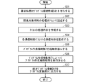
- FIG. 10 is a flowchart showing an execution procedure of the program generation assisting process by the program creation assisting unit 7.
- the operation contents of the program creation assisting unit 7 will be described with reference to FIG.
- step S21 the program creation assisting unit 7 receives the program information D6, the program environment information D4t with the requested time, and the program information D6t with the estimated time.
- the program information D6 is received from the program creation unit 1
- the program environment information D4t with the requested time is received from the input device 4 via the program creation unit 1
- the program information D6t with the estimated time is received from the execution time estimation unit 2.
- step S22 the program creation assisting unit 7 confirms the existence of an unspecified icon for which the OS or CPU is not defined based on the program information D6.
- step S22 if the undesignated icon exists (YES), the process proceeds to step S25, and if the undesignated icon does not exist (NO), the process proceeds to step S23.
- step S23 which is executed in the case of NO in step S22, the program environment information D4t with the requested time and the program information D6t with the estimated time are compared.
- the request execution time information in the program environment information D4t with the required time includes a plurality of request processing times and the required number of requested communication times, and the program information with the estimated time D6t contains the plurality of estimated processing times and the required number of requested communication times. Estimated communication time and is included.
- step S24 the program creation assisting unit 7 confirms the existence of the dissatisfied icon and the dissatisfied communication path, and if the dissatisfied icon or the dissatisfied communication path exists (YES), the process proceeds to step S25, and the dissatisfied icon and the dissatisfied communication path are present. If there is no unsatisfied communication path (NO), the process ends.
- the program creation assisting unit 7 can determine the presence or absence of the dissatisfaction icon based on the comparison result between the plurality of request processing times and the plurality of estimated processing times, and the required number of requested communication times and the required number of estimated communication times The presence or absence of an unsatisfied communication path can be determined based on the comparison result.
- step S25 the program creation assisting unit 7 executes the first allocation assisting process or the second allocation assisting process. After YES in step S22, the first allocation assist process is executed, and after YES in step S24, the second allocation assist process is executed.
- the first and second allocation auxiliary processes are icons so as to satisfy the instruction contents of the request execution time information including the request total execution time RT, a plurality of request processing times, and the required number of requested communication times. Is a process of executing the allocation to the CPU and the OS by using the SAT solver and the learner described above.
- step S26 it is confirmed whether or not the first or second allocation auxiliary process executed in step S25 is successful, and if the success is confirmed (YES), the process is terminated. That is, when the first or second allocation assisting process of step S25 satisfies the instruction content of the request execution time information and the CPU and the OS are assigned to the plurality of icons, the step S26 becomes YES, so that If not, step S26 is NO.
- step S27 the unsuccessful notification process for notifying that the allocation assist process was unsuccessful is executed in step S27.
- the unsuccessful notification process can be executed, for example, by displaying information indicating unsuccess on the display device 5 from the program creation assisting unit 7 via the program creation unit 1.
- one of the first and second allocation assisting processes is selectively executed. That is, the second allocation assisting process is executed only when YES in step S22 and YES in step S24.
- the processing procedure shown in FIG. 11 may be modified so that the first and second allocation auxiliary processing are performed together. That is, even if NO in step S22, if YES in step S24, the flow may be changed so that the second allocation assist process is executed.
- FIG. 11 is a flowchart showing a processing procedure of a program creation process using the program creation support device 72 of the second embodiment.
- step S31 the operator assigns the program environment information D4t with the required time regarding the development target HW to the program creation unit 1 using the input device 4.
- steps S32 to S34 and S37 is performed in the same manner as the processing of steps S12 to 14 and S18 of the first embodiment shown in FIG. 7.
- step S35 executed after step S34, the program creation assisting unit 7 is put into the activated state. That is, information instructing the start of operation of the program creation assisting unit 7 is given from the input device 4.
- step S36 the program creation assisting unit 7 executes the program creation assisting process.
- the program creation auxiliary process includes the first and second allocation auxiliary processes shown in FIG.
- step S37 the current program information D6 is output to the program conversion unit 3 as the finalized program information D6f.
- the dedicated program information D3 for the development target HW can be obtained by the program conversion process by the program conversion unit 3.
- step S37 is executed when YES is set in step S26 among the program creation assisting processes shown in FIG. 10, and is not executed when NO is set in step S26.
- the program creation support device 72 of the second embodiment is characterized by having a program creation assisting unit 7 for executing the program creation assisting process.
- the program creation auxiliary process includes the first and second allocation auxiliary processes.
- the program creation assisting unit 7 requests the entire request execution time RT, a plurality of request processing times, and a required number of requested communication times for each of at least one unspecified icon.
- the first allocation auxiliary process for automatically allocating the CPU and the OS is executed so as to satisfy the instruction content of the execution time information.
- the program creation support device 72 of the second embodiment automatically executes a program that satisfies the instruction content of the request execution time information without imposing a burden on the operator who is the user even if the unspecified icon exists. Can be created in.
- the program creation support device 72 of the second embodiment can automatically create a program that satisfies the instruction content of the request execution time information even if the plurality of icons are all unspecified icons.
- the program creation assisting unit 7 automatically allocates the CPU and the OS to at least one dissatisfied icon and at least one dissatisfied communication path so as to satisfy the instruction content of the request execution time information. To execute further.
- the program creation support device 72 of the second embodiment is a program that satisfies the instruction content of the request execution time information without imposing a burden on the operator who is the user even if the dissatisfied icon or the dissatisfied communication path exists. Can be created automatically.
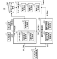
- FIG. 12 is a block diagram showing the configuration of the program creation support device 73 according to the third embodiment of the present disclosure.
- the program creation support device 73 of the third embodiment has the execution time estimation unit 2 and the program creation assisting unit 7 of the program creation support device 72 of the second embodiment, and the execution time estimation unit 2X and the program creation.
- the feature is that it is replaced with the auxiliary unit 8.
- the execution time estimation unit 2X receives the program environment information D4t with the requested time and the program information D6, and executes the execution time estimation process for obtaining the estimated program execution time including the probability distribution for the program.
- the execution time estimation unit 2X includes a processing time estimation unit 21X with a probability distribution and a communication time estimation unit 22X with a probability distribution as main components.
- the processing time estimation unit 21X with a probability distribution refers to the program environment information D4t with the requested time and the program information D6, and responds to each of the plurality of icons instructed by the program information D6 based on the designated CPU and OS.
- the processing time estimation processing for estimating the processing time of the assigned processing and obtaining the estimated processing time with a probability distribution is executed.
- the processing time estimation processing by the rational time estimation unit 21X it is possible to obtain an estimation processing time with a plurality of probability distributions corresponding to a plurality of icons. From the estimated processing times with a plurality of probability distributions, it is possible to recognize the probability distributions of a plurality of estimated processing times corresponding to a plurality of icons.
- the estimated processing time with a plurality of probability distributions includes the probabilities of satisfying the corresponding plurality of request processing times.
- the communication time estimation unit 22X with a probability distribution refers to the program environment information D4t with the requested time and the program information D6, and is based on the designated CPU and OS for each of the required number of communication paths specified in the program information D6. , Executes the communication time estimation process to estimate the communication time and obtain the estimated communication time with probability distribution.
- the communication time estimation unit 22X by executing the communication time estimation process by the communication time estimation unit 22X with a probability distribution, it is possible to obtain a plurality of estimated communication times with a probability distribution corresponding to the required number of communication paths. From the estimated communication times with a plurality of probability distributions, it is possible to recognize the probability distribution of the required number of estimated communication times corresponding to the required number of communication paths.
- the estimated communication time with a plurality of probability distributions includes the probabilities of satisfying the corresponding multiple requested communication times.
- the estimated program execution time obtained by the execution time estimation unit 2X includes an estimation processing time with a plurality of probability distributions corresponding to a plurality of icons and a required number of probability distributions corresponding to the required number of communication paths. Estimated communication time is included.
- the execution time estimation unit 2X outputs the program information D6t with the estimated time in which the above-mentioned estimated program execution time is added to the program information D6.
- the program information D6t with an estimated time is instructed to have a probability of satisfying the corresponding requested processing time for each of the plurality of estimated processing times and a probability of satisfying the corresponding requested communication time for each of the required number of estimated communication times. Contains information.
- the program information D6x with probability distribution includes the probability distribution of the estimated total execution time AT and the information indicating the probability that the estimated total execution time AT satisfies the requested total execution time RT.
- the processing time estimation process by the processing time estimation unit 21X with a probability distribution and the communication time estimation process by the communication time estimation unit 22X with a probability distribution are estimated many times by repeating a simulation considering a specified OS and CPU, for example. It can be performed by estimating the processing time and the estimated communication time and performing statistical processing based on the estimation result.
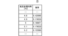
- FIG. 13 and 14 are explanatory diagrams showing an example of the estimation result 25 of the estimation processing time with probability distribution.
- the estimation result 25 is the estimation result of the icon 51 corresponding to the process A.
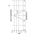
- FIG. 13 shows the estimated processing time with a probability distribution in a graph format, and the probability distribution PD1 is shown in a format corresponding to the estimated processing time (ms).
- FIG. 14 shows the estimated processing time with a probability distribution in a table format, and the probability is shown in association with the estimated processing time (ms).
- FIG. 15 is an explanatory diagram showing the relationship between the estimated processing time with probability distribution and the requested processing time shown in FIG. 13 in a graph format. As shown in the figure, the case where the request processing time requested for the processing A of the icon 51 is 5.1 (ms) is shown, and the line extending vertically from 5.1 ms is the reference probability line PS1. ..
- the ratio of the area of the area RP1 on the left side of the reference probability line PS1 to the total area of the total area of 0 or more of the probability distribution PD1 indicates the probability of satisfying the required processing time, and the area on the right side of the reference probability line PS1. It shows the probability that the ratio of the area of RP2 to the whole area does not satisfy the required processing time.
- the areas of the regions RP1 and RP2 can be obtained by performing an integral operation on the probability distribution PD1.
- the processing time estimation unit 21X with a probability distribution of the execution time estimation unit 2X calculates the estimation result 25 as shown in FIG. 15 for each icon, and the processing corresponding to each icon is performed. Is executing a processing time estimation process for obtaining an estimated processing time with a probability distribution.
- the communication time estimation unit 22X with a probability distribution of the execution time estimation unit 2X corresponds to each communication path by calculating the estimation result similar to the estimation result 25 shown in FIGS. 13 to 15 for each communication path.
- the communication time estimation process for obtaining the estimated communication time with a probability distribution is executed.
- FIG. 16 is an explanatory diagram showing an example of the estimation result 26 of the estimation total execution time with probability distribution in a graph format. As shown in the figure, the probability distribution PD0 is shown in a format corresponding to the estimated total execution time (ms).
- the ratio of the area RA1 on the left side of the reference probability line PS0 to the total area of the total area of 0 or more of the probability distribution PD0 indicates the probability of satisfying the required processing time, and the area on the right side of the reference probability line PS0. It shows the probability that the ratio of the area of RA2 to the whole area does not satisfy the required processing time.
- the areas of the regions RA1 and RA2 can be obtained by performing an integral operation on the probability distribution PD0.
- the execution time estimation unit 2X executes an execution time estimation process for obtaining an estimated total execution time with a probability distribution by calculating an estimation result 26 regarding the estimated total execution time AT.
- the estimation result 26 shown in FIG. 16 can be obtained by, for example, the following first and second estimation methods.
- the first estimation method is a method of obtaining the probability distribution of the estimated total execution time AT by repeating the simulation.
- the simulation described above is a simulation for executing a program including a plurality of icons and a required number of communication paths.
- the second estimation method is a method of calculating using a plurality of estimated processing times with probability distributions and an estimated communication time with a required number of probability distributions. That is, the second method is to obtain the joint probability distribution of the estimated processing time with probability distribution of each icon and the estimated communication time with probability distribution of each communication path for a plurality of icons and the required number of communication paths. It is an estimation method. It should be noted that each estimated processing time with a probability distribution includes a probability of satisfying the corresponding request processing time, and each estimated communication time with a probability distribution includes a probability of satisfying the corresponding requested communication time.
- the program creation assisting unit 8 receives the program information D6 created by the program creation unit 1 and the program environment information D4t with a requested time via the program creation unit 1.
- the program creation assisting unit 8 executes the program creation assisting process with reference to the program information D6t with the estimated time from the execution time estimation unit 2X based on the program information D6x with the probability distribution and the program environment information D4t with the required time.
- the program creation auxiliary process executed by the program creation auxiliary unit 8 is a probability-based allocation auxiliary process that automatically allocates a CPU and an OS to each of a plurality of icons so that the probability of satisfying the entire request execution time RT is maximized. Is.
- the program creation assisting unit 8 appropriately refers to the program information D6t with the estimated time from the execution time estimation unit 2X during the execution of the probability reference allocation assisting process, so that the icon or communication in which the CPU and OS allocations are added or changed is added or changed. With respect to the route, it is possible to confirm whether or not the probability of satisfying the entire request execution time RT is maximized.
- the processing target of the program creation assisting unit 8 is all a plurality of icons.
- the estimation result 26 of the estimated total execution time can be repeated from the execution time estimation unit 2X by using the first estimation method while changing the allocation of the CPU and the OS to a plurality of icons.
- An overall priority estimation method can be considered.
- the probability of satisfying the request processing time corresponding to a plurality of icons is the highest, and the probability of satisfying the requested communication time corresponding to the required number of communication paths is the highest.
- an individual priority estimation method for setting the allocation of the CPU and the OS to a plurality of icons can be considered.
- the individual priority estimation method is premised on the process of being able to repeat a plurality of estimated processing times with probability distributions and the required number of estimated communication times with probability distributions from the execution time estimation unit 2X by using the second estimation method. It becomes the estimation method.
- the estimated total execution time with a probability distribution is derived by obtaining the joint probability distribution of the entire program from the estimation result 25 described above.
- the hardware configuration of the third embodiment is also as shown in FIG. 18, as in the first and second embodiments.
- the program creation assisting unit 8 and the execution time estimation unit 2X are realized by the computer 102 executing the application program.
- the program creation auxiliary process executed by the program creation auxiliary unit 8 automatically automates the CPU and the OS so that the probability of satisfying the entire request execution time RT is the highest for each of the plurality of icons to be processed. Probability-based allocation assistance processing.
- FIG. 17 is a flowchart showing a processing procedure of a program creation process using the program creation support device 73 of the third embodiment.
- steps S41 to S44 and S47 are performed in the same manner as the processes of steps S31 to 34 and S37 of the second embodiment shown in FIG.
- step S45 executed after step S44, the program creation assisting unit 8 is put into the activated state. That is, information instructing the start of operation of the program creation assisting unit 8 is given from the input device 4.
- step S46 the program creation assisting unit 8 causes the above-mentioned probability-based allocation assisting process to be executed with all of the plurality of icons as processing targets.
- the program creation support device 73 of the third embodiment it is possible to develop a program having the highest probability of satisfying the entire requested execution time RT desired by the operator as a user even if there is a process having a large fluctuation range of the execution time. It can be carried out.
- the processing target of the probability standard allocation auxiliary processing executed in step S46 is all a plurality of icons, but the processing target may be limited as in the second embodiment.
- the undesignated icon, the unsatisfied icon, and the unsatisfied communication route may be limited so as to be the processing target of the probability standard allocation auxiliary processing.
- the judgment content of the dissatisfaction icon is that the probability of not satisfying the request processing time is lower than the standard, and that the probability of not satisfying the requested communication time is lower than the standard as the dissatisfaction communication path.
- the program creation assisting unit 8 in the program creation support device 73 of the third embodiment automatically automates the CPU and the OS so that the probability of satisfying the entire request execution time RT is the highest for each of the plurality of icons to be processed. Probability-based allocation assistance processing is being executed.
- the program creation support device 73 of the third embodiment can automatically create a program having the highest probability of satisfying the entire request execution time RT without imposing a burden on the operator who is the user.
- the program creation support device 73 of the third embodiment uses the program information D6x with a probability distribution, so that even if the probability of satisfying the entire request execution time RT is relatively low, the user can use the best program at present. It can be shown to an operator.
- the communication method applied to each of the required number of communication paths is selected as the selection communication method from among the plurality of types of communication methods. Includes communication method selection processing.
- the communication method selection process is usually performed by an operator who is a user using the input device 4, but a modified example in which the communication content description unit 112 automatically performs the communication method selection process is also conceivable.
- a plurality of types are used for the communication time estimation process of the communication time estimation unit 22 (communication time estimation unit 22X with probability distribution) of the execution time estimation unit 2 (2X) for each of the required number of communication paths. It includes an estimation process for each communication method that obtains the estimated communication time for each communication method as an estimation result for each communication method.
- the communication content description unit 112 causes the execution time estimation unit 2 to execute the estimation process for each communication method and obtains the estimation result for each communication method, whereby the estimated communication time among the plurality of types of communication methods is obtained.
- the shortest communication method can be automatically selected as the selected communication method.
- the communication content description unit 112 in the modified example of the program creation support device of the present embodiment is based on the estimation result for each communication method from the communication time estimation unit 22, and the estimated communication time among the plurality of types of communication methods is estimated.
- the communication method selection process for selecting the shortest communication method as the selection communication method is automatically executed.
- each embodiment can be freely combined, and each embodiment can be appropriately modified or omitted.
- Program creation unit 1, 2X Execution time estimation unit, 3 Program conversion unit, 4 Input device, 5 Display device, 7, 8 Program creation assistance unit, 11 Chart creation unit, 12 Processing content creation unit, 21 Processing time estimation unit , 21X Processing time estimation unit with probability distribution, 22 Communication time estimation unit, 22X Communication time estimation unit with probability distribution, 31 Processing code generation unit, 32 Communication code generation unit, 33 Setting code generation unit, 71-73 Program creation support device ..
Landscapes
- Engineering & Computer Science (AREA)
- Software Systems (AREA)
- General Engineering & Computer Science (AREA)
- Theoretical Computer Science (AREA)
- Physics & Mathematics (AREA)
- General Physics & Mathematics (AREA)
- Stored Programmes (AREA)
Abstract
本開示は、ユーザが所望する時間内で実行するプログラムの作成を的確に支援するプログラム作成支援装置を提供することを目的とする。そして、本開示のプログラム作成支援装置(71)は、プログラム作成部(1)及び実行時間推定部(2)を備え、実行時間推定部(2)は処理時間推定部(21)及び通信時間推定部(22)を含む。処理時間推定部(21)は、プログラム作成部(1)で作成された複数のアイコンそれぞれに対し、指定されたCPU及びOSに基づき、対応づけられた処理の処理時間を推定して推定処理時間を得る処理時間推定処理を実行する。通信時間推定部(22)は、必要数の通信経路それぞれに対し、指定されたCPU及びOSに基づき、通信時間を推定して推定通信時間を得る通信時間推定処理を実行する。
Description
本開示は、並列リアルタイム処理装置で実行されるプログラムの開発を支援するプログラム作成支援装置に関するものである。
従来、並列リアルタイム処理装置で実行されるプログラムを開発するためのプログラム作成支援装置として、例えば、特許文献1に開示されたプログラム開発装置がある。
このプログラム開発装置は、ダイアグラムを作成するためのアイコンの選択等を行う入力装置と、作成途中または作成されたダイアグラムを表示させるための表示装置と、ダイアグラムを作成するダイアグラム作成部と、ダイアグラムの作成に用いられるアイコンに対応したプログラム実体を記憶するアイコン記憶部とを備えている。さらに、プログラム開発装置は、作成されたダイアグラムを記憶するダイアグラム記憶部と、作成されたダイアグラムを解釈し実行するインタプリタと、複数のオブジェクトにより構成されるオブジェクトライブラリとを備えている。
特許文献1で開示されたプログラム開発装置に代表される従来のプログラム作成支援装置は、並列リアルタイム処理装置を実行するシステムのHW(hardware)やSW(software)の構成を記述できない。このため、複数のCPU(Central Processing Unit)、OS(Operating System)から構成される計算機で処理を実行する場合には、各処理を実行するCPU、OSを考慮した設計が別途必要であり、手間が発生していた。
また、ユーザは、プログラム作成支援装置を使用しているプログラム作成段階で、指定されたCPU,OSの環境下における処理の実行に要する時間を容易に確認できないことから、作成したプログラムがユーザ所望の時間内に終了するか否かを認識することが比較的困難であった。
したがって、従来のプログラム作成支援装置を用いた場合、並列リアルタイム処理装置に要求される仕様を確実に満たすようにプログラムを作成することが難しいという問題点があった。
本開示では、上記のような問題点を解決し、ユーザが所望する時間内で実行するプログラムの作成を的確に支援するプログラム作成支援装置を提供することを目的とする。
本開示に係るプログラム作成支援装置は、並列リアルタイム処理装置用のプログラム作成支援装置であって、前記並列リアルタイム処理装置が使用するCPU及びOSの構成を含むプログラム環境情報を付与する入力装置と、前記プログラム環境情報により規定されるCPU及びOSを使用してプログラムを作成し、前記プログラムの内容を示すプログラム情報を出力するプログラム作成部と、前記プログラム情報を受け、前記プログラムに関する推定プログラム実行時間を得る実行時間推定処理を実行する実行時間推定部とを備え、前記プログラム作成部は、前記プログラムを構成する複数の処理を複数のアイコンに対応づけ、前記複数のアイコンそれぞれに対しCPU及びOSを指定し、前記複数のアイコン間の実行順序関係を記述する処理構成記述処理を実行する処理構成記述部と、前記複数のアイコン間における必要数の通信経路それぞれの通信内容を記述する通信内容記述処理を実行する通信内容記述部とを含み、前記実行時間推定部は、前記複数のアイコンそれぞれに対し、指定されたCPU及びOSに基づき、対応づけられた処理の処理時間を推定して推定処理時間を得る処理時間推定処理を実行する処理時間推定部と、前記必要数の通信経路それぞれに対し、指定されたCPU及びOSに基づき、通信時間を推定して推定通信時間を得る通信時間推定処理を実行する通信時間推定部とを含み、前記処理構成記述処理及び前記通信内容記述処理は、前記入力装置を用いたユーザ操作に連動して実行され、前記処理時間推定処理及び前記通信時間推定処理の実行開始の指示は前記入力装置を用いたユーザ操作によって行われ、前記実行時間推定処理は前記処理時間推定処理及び前記通信時間推定処理を含み、前記推定プログラム実行時間は前記複数のアイコンそれぞれの前記推定処理時間及び前記必要数の通信経路それぞれの前記推定通信時間を含み、前記プログラム作成支援装置は、前記複数のアイコンそれぞれに前記推定処理時間を対応づけ、かつ、前記必要数の通信経路それぞれに前記推定通信時間を対応づけた推定時間付プログラム情報を画面上に表示する表示装置をさらに備える。
本開示のプログラム作成支援装置は、処理時間推定部及び通信時間推定部に処理時間推定処理及び通信時間推定処理を実行させることより、指定されたCPU及びOSに基づき、複数のアイコンそれぞれの推定処理時間と、必要数の通信経路それぞれの推定通信時間とを推定プログラム実行時間として得ることができる。
したがって、ユーザは複数のアイコンへのCPU及びOSの対応づけを適宜変更して、表示装置の画面上に表示された推定時間付プログラム情報を参照することにより、プログラムの全体実行時間に悪影響を与える要因を比較的容易に認識することができる。
その結果、本開示のプログラム作成支援装置は、ユーザが所望する時間内で実行するプログラムの作成を効果的に支援することができる。
本開示の目的、特徴、局面、および利点は、以下の詳細な説明と添付図面とによって、より明白となる。
<実施の形態1>
図1は本開示の実施の形態1であるプログラム作成支援装置71の構成を示すブロック図である。
図1は本開示の実施の形態1であるプログラム作成支援装置71の構成を示すブロック図である。
同図に示すように、プログラム作成支援装置71は、プログラム作成部1、実行時間推定部2、プログラム変換部3、入力装置4及び表示装置5を主要構成要素として含んでいる。
入力装置4は、並列リアルタイム処理装置が使用するCPU及びOSの構成を含むプログラム環境情報D4を外部より受け、プログラム環境情報D4をプログラム作成部1に付与している。プログラム環境情報D4は通常、複数のCPU及び複数のOSを指示する。ただし、プログラム環境情報D4の指示内容のうちCPU及びOSのうち一方は一つであっても良い。
プログラム作成部1は、プログラム環境情報D4により規定されるCPU及びOSを使用してプログラムを作成する。そして、プログラム作成部1は、作成したプログラムの内容を示すプログラム情報D6を実行時間推定部2、プログラム変換部3及び表示装置5に出力する。以降、プログラム作成部1で作成したプログラムを実際に実行する並列リアルタイム処理装置を「開発対象HW」と呼ぶ場合がある。
実行時間推定部2は、プログラム情報D6を受け、プログラムに関する推定プログラム実行時間を得る実行時間推定処理を実行する。
プログラム作成部1はチャート作成部11及び処理内容作成部12を主要構成要素として含んでいる。チャート作成部11は作成するプログラムの構造をアイコンとアイコン同士の接続により記述する。すなわち、チャート作成部11は、プログラムを構成する複数の処理を複数のアイコンに対応づけている。さらに、チャート作成部11は処理構成記述部111及び通信内容記述部112を主要構成要素として含んでいる。
処理構成記述部111は、プログラム環境情報D4から開発対象HWが使用するCPUとOSの情報を認識する。
そして、処理構成記述部111は、プログラムを構成する複数の処理を複数のアイコンに対応づけ、複数のアイコンそれぞれにおいてCPU及びOSを指定し、複数のアイコン間の実行順序関係を記述する処理構成記述処理を実行する。以下、本明細書において用いる「アイコン」は「処理」に対応するプログラム構成要素を意味する。また、プログラム構成要素としては、プログラムモジュール、プログラムを構成する関数、関数のまとまり等が考えられる。
通信内容記述部112は、複数のアイコン間における必要数の通信経路それぞれの通信内容を記述する通信内容記述処理を実行する。なお、通信内容には、使用する通信方式及び通信するデータの内容が含まれる。
処理内容作成部12は、複数のアイコンそれぞれの処理内容を作成する処理内容作成処理を実行する。
上記処理構成記述処理、上記通信内容記述処理及び上記処理内容作成処理は、入力装置4を用いた操作者によるユーザ操作に連動して実行される。
プログラム作成部1は、上記処理構成記述処理、上記通信内容記述処理及び上記処理内容作成処理を実行することによりプログラムを作成し、作成されたプログラムの内容を示すプログラム情報D6を得る。プログラム情報D6は、実行順序が指定された複数のアイコン、複数のアイコンそれぞれに指定されたCPU及びOS、必要数の通信経路及び複数のアイコンの処理内容を指示する情報である。
実行時間推定部2は処理時間推定部21及び通信時間推定部22を主要構成要素として含んでいる。
処理時間推定部21は、プログラム情報D6を参照して、プログラム情報D6で指示される複数のアイコンそれぞれに対し、指定されたCPU及びOSに基づき、対応づけられた処理の処理時間を推定して推定処理時間を得る処理時間推定処理を実行する。したがって、処理時間推定部21による処理時間推定処理の実行により、複数のアイコンに対応する複数の推定処理時間を得ることができる。
通信時間推定部22は、必要数の通信経路それぞれに対し、指定されたCPU及びOSに基づき、通信時間を推定して推定通信時間を得る通信時間推定処理を実行する。したがって、通信時間推定部22による通信時間推定処理の実行により、必要数の通信経路に対応する必要数の推定通信時間を得ることができる。
したがって、実行時間推定部2が得る推定プログラム実行時間は、複数のアイコンそれぞれの推定処理時間及び必要数の通信経路それぞれの推定通信時間を含んでいる。
このように、実行時間推定部2は、処理時間推定処理及び通信時間推定処理を含む実行時間推定処理を実行して、プログラム情報D6に上述した推定プログラム実行時間を加味した推定時間付プログラム情報D6tを得ることができる。
本明細書中において、上述した推定プログラム実行時間を加味したプログラム情報D6を、「推定時間付プログラム情報D6t」と呼ぶ場合がある。推定時間付プログラム情報D6tは、複数のアイコンそれぞれに推定処理時間を対応づけ、かつ、必要数の通信経路それぞれに推定通信時間を対応づけた情報となる。
さらに、実行時間推定部2は、複数の推定処理時間及び必要数の推定通信時間から、プログラム全体の推定全体実行時間ATを求め、推定プログラム実行時間に推定全体実行時間ATを含めている。
また、実行時間推定処理に含まれる処理時間推定処理及び通信時間推定処理それぞれの実行開始の指示は入力装置4を用いたユーザ操作によって行われる。
一方、プログラム作成部1によるCPU及びOSの対応づけが確定したプログラムが確定プログラムとして規定され、プログラム情報D6のうち、確定プログラムの内容を示す情報を特に「確定プログラム情報D6f」と呼ぶ場合がある。確定プログラム情報D6fには、複数のアイコンと必要数の通信経路と複数のアイコンへの指定が確定したCPU及びOSと、複数のアイコンの処理内容とが含まれる。
プログラム変換部3は、確定プログラム情報D6fを受け、開発対象HWが実行する専用プログラムに変換し、専用プログラムの内容を示す専用プログラム情報D3を作成する。
プログラム変換部3は、処理コード生成部31、通信コード生成部32及び設定コード生成部33を主要構成要素として含んでいる。
処理コード生成部31は、確定プログラム情報D6fで指示された複数のアイコンの処理を、開発対象HW用の複数の処理コードに変換する。
通信コード生成部32は、確定プログラム情報D6fで指示された必要数の通信経路を開発対象HW用の必要数の通信コードに変換する。
設定コード生成部33は、確定プログラム情報D6fの指示内容に基づき、複数のアイコンに割り当てたCPU及びOSを、開発対象HW用の複数のOS・CPUコードとして生成する。
したがって、専用プログラム情報D3には、開発対象HW用の複数の処理コード、必要数の通信コード、複数のOS・CPUコードが含まれる。
入力装置4は、操作者による操作であるユーザ操作を受け付け、少なくとも、開発対象HWのCPUの個数、OSの種類、それぞれのCPUの性能値に関するプログラム環境情報D4をプログラム作成部1に付与する。なお、プログラム環境情報D4の全部または一部を外部から入力装置4を介して取り込むようにしても良い。
さらに、入力装置4を用いたユーザ操作によって、プログラム作成部1、実行時間推定部2、プログラム変換部3を動作させることができる。
表示装置5は、プログラム情報D6あるいは推定時間付プログラム情報D6tの内容を操作者が視覚認識できる態様で画面上に表示する。
図18はプログラム作成支援装置71のハードウェア構成を模式的に示すブロック図である。同図に示すように、データの送受信を行うバス105にキーボード101、計算機102、メモリ103及びディスプレイ104が接続されている。
計算機102は、メモリ103または内部に格納されるアプリケーションプログラムを実行するCPU(Central Processing Unit、中央処理装置、処理装置、演算装置、マイクロプロセッサ、マイクロコンピュータ、プロセッサ、DSPともいう)を有している。
メモリ103として、例えば、RAM、ROM、フラッシュメモリー、EPROM、EEPROM等の、不揮発性または揮発性の半導体メモリが考えられる。さらに、メモリ103は、磁気ディスク、フレキシブルディスク、光ディスク、コンパクトディスク、ミニディスク、DVD等、または、今後使用されるあらゆる記憶媒体であってもよい。
プログラム作成部1、実行時間推定部2、プログラム変換部3はすべて、計算機102がアプリケーションプログラムを実行することにより実現される。入力装置4は、計算機102に接続されるキーボード101が該当し、他に図18では図示しないマウスも含まれる。また、プログラム環境情報D4の少なくとも一部を外部から取り込む場合は、入力装置4として入力ポートが含まれる。
表示装置5は、計算機102にバス105を介して接続されるディスプレイ104が該当する。プログラム情報D6はメモリ103や計算機102内の記録装置に記録される。
図2はチャート作成部11で作成されるチャート(初期状態)の概念を示す説明図である。図2に示すように、チャート作成部11には、入力装置4からプログラム環境情報D4として付与された開発対象HW用のCPU及びOSの情報と、各CPUとOSに処理を割り当てるための領域と、処理時間や通信時間を直観的に理解可能とするための時間軸を含むチャートを表示装置5の画面上に表示する。
チャート作成部11の主要構成要素である処理構成記述部111では、各CPUとOSに対応する領域にアイコンを配置することにより、アイコンに対応する処理を実行するCPUとOSを選択することができる。
なお、図2で示す例では、OS-A用にCPU1及びCPU2が割り当てられ、OS-B用にCPU3が割り当てられている。この場合、プログラム環境情報D4は、CPU1~CPU3とOS-A及びOS-BをCPU及びOSの構成として指示している。
また、アイコン同士を接続することにより、アイコンの実行順序を決定している。さらに、アイコンにピンを追加することにより、アイコンから出力される、もしくは、アイコンに入力されるデータがあることを示すことができる。
図3はアイコン単体のイメージを示す説明図であり、図4はアイコン間の通信経路のイメージを示す説明図である。
図3に示すように、アイコン50は処理aに対応して設定される。図4に示すように、アイコン51及び52は処理A及び処理Bに対応して設定される。さらに、アイコン51の出力側のピン61とアイコン52の入力側のピン62とが通信経路CP1により接続される。通信経路CP1は、アイコン51からアイコン52に向けて通信処理がなされることを示している。
このように、一対のアイコンに関し、一方のアイコンの出力側のピンと他方のアイコンの入力側のピンとを接続することにより、一方のアイコンから他方アイコンに向かう方向に通信経路が存在することを示している。
チャート作成部11の主要構成要素である通信内容記述部112は、処理構成記述部111で作成されたアイコン間の通信経路CPについて、その通信内容を記述する。通信内容は、チャート上でピン同士を接続した通信経路CPについて、チャートとは異なる別ウィンドウで記述する。
図5は別ウィンドウに表示される通信経路のイメージを示す説明図である。図5に示すように、アイコン51が指示された「処理A」からアイコン52で指示された「処理B」への通信経路CPが記述されている。
図5に示すように、アイコン51の出力側のピン61a~61cから出力データとなる変数a~変数cを出力する。一方、アイコン52の入力側ピン62d~62fは変数d~変数fを入力データとして受ける。この際、アイコン51から出力される変数aがアイコン52の変数eとしてピン62eに入力され、アイコン51から出力される変数bがアイコン52の変数dとしてピン62dに入力され、アイコン51から出力される変数cがアイコン52の変数fとしてピン62fに入力される。
このように、図5は、アイコン51及び52間で変数a~変数cと変数d~変数fとのデータ通信を行う通信経路CPが設けられることを示している。
なお、通信経路CPごとに採用する通信方式を決定することができる。通信方式は通信経路CPを示す線の近傍に通信方式の名称を表示することなどにより、操作者が通信方式を直観的に認識できるようにしている。また、通信方式ごとに通信経路CPを指示する線種を異なる内容に表示するようにしても良い。
通信方式として、例えば、ソケット、共有メモリ、パイプなどの通信方式がある。ソケットは、双方向に通信でき、共有メモリによる通信よりも信頼性の高い通信方式である。パイプは、通信が一方向にしかできないが、ソケットより単純な通信方式である。共有メモリによる通信は、送信側と受信側がともにアクセス可能なメモリ上にデータを格納し、送信側と受信側でデータの受け渡しを行う方式である。
通信速度の観点から、共有メモリを使う通信方式が最も早いが、アクセスするアドレスを誤ると致命的なエラーが生じるなど、実装を誤ると信頼性が低くなるデメリットを有している。
一方、ソケット、パイプは、信頼性は高い反面、通信速度は遅くなる。このため、ソケット、共有メモリ、パイプを含む複数の通信方式のうち、どの通信方式を採用するかはケースバイケースとなる。
複数の通信方式から選択するに際し、プログラム環境情報D4に選択対象となる複数の通信方式が含まれている。
図6はチャート作成部11で作成されたチャート(作成段階)の例を模式的に示す説明図である。図6で示す例では、処理A~処理Dに対応して4つのアイコン51~54が設定されている。
そして、アイコン51はCPU1に、アイコン52はCPU2に、アイコン53及び54はCPU3に割り当てられる。
アイコン51からアイコン52及び53に向けて実行順序を示す矢印が示され、アイコン52及び53からアイコン54に向けて実行順序を示す矢印が示されている。したがって、図6では、アイコン51~54間において、アイコン51、アイコン52及び53、アイコン54の順に実行されることを示している。なお、アイコン52及び53はCPU2及びCPU3が実行する並列処理となる。
さらに、アイコン52の出力側のピン62とアイコン54の入力側のピン64とが通信経路CP2により接続される。したがって、図6では、アイコン52とアイコン54との間に通信経路CP2を介した通信処理が行われることを示している。
各アイコンに対応する処理内容は、処理内容作成部12により作成される。処理内容作成部12は、チャート作成部11と同様のアイコンを使用したチャート形式であっても、外部ツールにより作成する形式であってもよい。作成された処理内容は、アイコンと対応付けて管理される。
プログラム作成支援装置71によって作成するプログラム情報D6には、複数のアイコン、必要数の通信経路、複数のアイコンの処理内容、複数のアイコンに対応するOS及びCPU、複数のアイコンの実行手順を指示する情報が含まれる。
図6の例では、アイコン51~54が複数のアイコンに対応し、通信経路CP1が必要数の通信経路に対応する。アイコン51~54間の矢印によって複数のアイコンの実行手順が示され、アイコン51~54が配置される位置によって、アイコン51~54それぞれを実行するOS及びCPUが指定されている。
実行時間推定部2は、プログラム作成部1で作成されたプログラム情報D6を受け、プログラム情報D6が指示するプログラムに関する推定プログラム実行時間を得る実行時間推定処理を実行する。
推定プログラム実行時間は、複数のアイコンそれぞれに対する推定処理時間、必要数の通信経路それぞれに対する推定通信時間及び推定全体実行時間ATが含まれる。以下、複数のアイコンそれぞれに対する推定処理時間の総称を「複数の推定処理時間」、必要数の通信経路それぞれに対する推定通信時間の総称を「必要数の推定処理時間」と呼ぶ場合がある。
上述した推定全体実行時間ATは、複数の推定処理時間及び必要数の推定処理時間に基づく加算を含む演算処理によって得ることができる。
したがって、実行時間推定部2は、プログラム情報D6に基づき、推定全体実行時間AT、複数の推定処理時間及び必要数の推定処理時間を含む推定プログラム実行時間を指示する情報をプログラム情報D6に加味した推定時間付プログラム情報D6tを得ることができる。推定時間付プログラム情報D6tは適宜、プログラム作成部1やプログラム変換部3に送信される。
実行時間推定部2によって推定時間付プログラム情報D6tが得られた場合、プログラム作成部1を経由して推定時間付プログラム情報D6tを表示装置5に付与することができる。
したがって、図6に示すように、時間軸に沿って、アイコン51~54に対応する推定処理時間T1~T4、通信経路CP2に対応する推定通信時間TC2、及び推定全体実行時間ATを表示装置5の画面上に表示することができる。
処理時間推定部21による処理時間推定処理は、各アイコンの処理内容を参照し、処理に必要なステップ数と、アイコンを実行するCPUの性能とに基づき、ハードウェアシミュレータを用いたシミュレーションや、前もって評価したステップ数と実行速度の関係に基づく演算処理として実行される。なお、各アイコンの処理内容は処理内容作成部12によって作成される。
通信時間推定部22による通信時間推定処理は、各通信経路上で通信する変数と、その通信方式に基づいて実行される。例えば、選択された通信方式に関し、前もって評価した、通信するデータ量及び通信方式と通信時間の関係を利用することにより、通信時間推定処理が実行できる。なお、各通信経路の通信方式や通信内容は通信内容記述部112によって作成される。
推定全体実行時間ATは、チャートの左端にある始点アイコンを起点として、接続されたアイコンを順に辿り、右端の終点アイコンまで辿った際の、各アイコンの推定処理時間と各通信経路CPにおける通信時間の総和となる。ただし、始点アイコンから終点アイコンまで複数のルートで辿ることができる場合には、複数ルートの推定実行時間のうち最悪値を推定全体実行時間ATとする。
プログラム作成部1で作成され、OS及びCPUの割り当てが完了した確定プログラムの内容を示す確定プログラム情報D6fはプログラム変換部3に付与される。プログラム変換部3は、確定プログラム情報D6fが示す確定プログラムを開発対象HWが実行する専用プログラムに変換し、専用プログラムを指示する専用プログラム情報D3を出力する。
専用プログラム情報D3には、上述したように、開発対象HWで実行される複数の処理コード、必要数の通信コードと、複数のOS・CPUコードが含まれる。
図7は実施の形態1のプログラム作成支援装置71を用いたプログラム作成処理の処理手順を示すフローチャートである。
以下、図7を参照して、実施の形態1のプログラム作成支援装置71を用いたプログラム開発の流れについて説明する。
プログラム作成処理は、実施の形態1のプログラム作成支援装置が起動されることによって開始される。
まず、ステップS11において、操作者は開発対象HWに関するプログラム環境情報D4を入力装置4からプログラム作成部1に付与する。プログラム環境情報D4には、開発対象HWが使用するCPUの個数、CPUの性能、OSの種類などが含まれる。プログラム環境情報D4は通常、複数のCPU及び複数のOSを指示する。
次に、ステップS12において、処理構成記述部111による処理構成記述処理によって、開発対象HWでの実行を所望する処理をアイコンで記述する。
その後、ステップS13において、処理内容作成部12による処理内容作成処理によって、ステップS12で記述したアイコンについて、その処理内容を作成する。なお、処理内容作成部12を用いることなく、外部の他のツールを使用して処理内容を作成するようにしても良い。
そして、ステップS14において、通信内容記述部112による通信内容記述処理によって、各通信経路における通信内容を記述する。
上述したステップS11~S14によって、プログラム情報D6として必要な情報が得られる。なお、ステップS11~S14の処理は、入力装置4を用いたユーザである操作者のユーザ操作に連動して行われる。
その後、ステップS15において、操作者が要求する実行時間内に、プログラム情報D6が指示するプログラムの実行が終了するかを確認する。ステップS15は操作者による確認処理である。以下、ステップS15について詳述する。
具体的には、実行時間推定部2に実行時間推定処理を実行させ、プログラム情報D6に基づき、推定時間付プログラム情報D6tを生成させる。同時に、プログラム作成部1を経由して推定時間付プログラム情報D6tを表示装置5に出力することにより、表示装置5の画面上に推定時間付プログラム情報D6tを視覚認識可能な形態で表示させる。
操作者は、表示装置5の画面上に表示される推定時間付プログラム情報D6tを参照して、推定全体実行時間ATを認識することにより、ステップS15のYES/NOを判断することができる。
すなわち、操作者が要求する要求全体実行時間RTと推定全体実行時間ATとの間で「RT≧AT」を満足すれば、ステップS15の判定結果はYESとなり、満足しなければステップS15の判定結果はNOとなる。
ステップS15がYESの場合、ステップS18において、現在のプログラム情報D6を確定プログラム情報D6fとしてプログラム変換部3に出力する。その結果、プログラム変換部3によるプログラム変換処理により、開発対象HW用の専用プログラム情報D3を得ることができる。ステップS18の実行後は処理を終了する。
ステップS15がNOの場合、操作者は、ステップS16及びS17のプログラム改善処理を行う。
まず、ステップS16において、推定時間付プログラム情報D6tの内容を検証する。推定時間付プログラム情報D6tには、推定全体実行時間ATに加え、複数の推定処理時間、必要数の推定通信時間が含まれている。
例えば、図6に示すように、アイコン51~54の推定処理時間T1~T4や通信経路CP2を参照することにより、操作者は、推定全体実行時間ATに悪影響を与えているアイコンあるいは通信経路を認識することができる。
次に、ステップS17において、操作者は、ステップS16の検証結果に基づき、個別改善処理を実行する。例えば。悪影響を与えているアイコンに関し、OS及びCPUの割り当てを変更したり、処理内容を変更したりする。同様に、悪影響を与えている通信経路に関し、OS及びCPUの割り当てを変更したり、通信内容を変更したりする。
上述した個別改善処理において、アイコンへのOS及びCPUの割り当て変更は比較的簡単に行え、各アイコンの処理時間及び各通信経路の通信時間を改善するための有効な対応策となる。なぜなら、アイコンの処理時間及び通信経路の通信時間は、割り当てたOS及びCPUに依存して変化するからである。
その後、再び、ステップS15に戻り、ステップS15でYESの場合はステップS18を経て処理を終了する。一方、ステップS15でNOの場合は再びステップS16及びS17の処理を行う。
図7に示すように実施の形態1のプログラム作成支援装置71を使用することができる。操作者は、プログラム作成支援装置71を使用して、プログラムを構成する各処理を実行するOSやCPUを設定しつつ、推定全体実行時間AT、各アイコンの推定処理時間、及び各通信経路の推定通信時間を考慮したプログラム作成を行うことができる。
したがって、実施の形態1のプログラム作成支援装置71を使用することにより、操作者が所望する要求全体実行時間RT内に実行可能なプログラムの開発を比較的容易に行うことができる。
上述したように、実施の形態1のプログラム作成支援装置71は、処理時間推定部21に処理時間推定処理を実行させ、通信時間推定部22に通信時間推定処理を実行させることより、指定されたCPU及びOSに基づき、複数のアイコンそれぞれの推定処理時間と、必要数の通信経路それぞれの推定通信時間を得ることができる。
したがって、ユーザとなる操作者は複数のアイコンへのCPU及びOSの対応づけを適宜変更して、表示装置5の画面上に表示された推定時間付プログラム情報D6tを参照することにより、プログラムの推定全体実行時間ATに悪影響を与えている要因を比較的容易に認識することができる。
そして、操作者は、プログラムの推定全体実行時間ATに悪影響を与えているアイコンまたは通信経路に対し、ステップS17の個別改善処理を実行することができる。
その結果、実施の形態1のプログラム作成支援装置71は、操作者が所望する要求全体実行時間RT内で実行するプログラムの作成を効果的に支援することができる。
加えて、実施の形態1のプログラム作成支援装置71は、処理内容作成部12による処理内容作成処理により、複数のアイコンそれぞれの処理内容を作成することができる。
したがって、操作者は複数のアイコンへのCPU及びOSの対応づけに加え、複数のアイコンの処理内容を適宜変更して、表示装置5の画面上に表示された推定時間付プログラム情報D6tを参照することができる。
その結果、実施の形態1のプログラム作成支援装置71は、操作者が所望する要求全体実行時間RT内で実行するプログラムの作成をより広範囲に支援することができる。
さらに、実施の形態1のプログラム作成支援装置71はプログラム変換部3を有している。したがって、操作者が所望する要求全体実行時間RT内で動作する開発対象HW用の専用プログラムを指示する専用プログラム情報D3を自動的に得ることができる。
<実施の形態2>
図8は本開示の実施の形態2であるプログラム作成支援装置72の構成を示すブロック図である。図8に示すように、実施の形態2のプログラム作成支援装置72は、実施の形態1のプログラム作成支援装置71に、プログラム作成補助部7を追加したことを特徴としている。
図8は本開示の実施の形態2であるプログラム作成支援装置72の構成を示すブロック図である。図8に示すように、実施の形態2のプログラム作成支援装置72は、実施の形態1のプログラム作成支援装置71に、プログラム作成補助部7を追加したことを特徴としている。
図8で示す各構成要素について、図1で示す実施の形態1と同一の構成要素には適宜、同一符号を付して説明を省略し、実施の形態2の特徴箇所を中心に説明する。
入力装置4は、プログラム作成補助部7による割当補助処理の起動を指示する指示情報を新たに受け付ける。
さらに、実施の形態2では、入力装置4から付与されるプログラム環境情報D4を要求時間付プログラム環境情報D4tに拡張している。要求時間付プログラム環境情報D4tは、プログラム環境情報D4に加え、プログラムの要求全体実行時間RT、複数の処理に対応する複数の要求処理時間、及び必要数の通信経路に対応する必要数の要求通信時間を指示する要求実行時間情報が含まれている。
なお、実施の形態2のハードウェア構成も実施の形態1と同様に図18で示す通りである。ただし、新たに追加されたプログラム作成補助部7は、計算機102がアプリケーションプログラムを実行することにより実現される。
図9はチャート作成部11で作成されたチャートの例を模式的に示す説明図である。図9で示す例では、処理A~処理Eに対応して5つのアイコン51~55が設定されている。また、OS-A用にCPU1及びCPU2が割り当てられ、OS-B用にCPU3が割り当てられている。
そして、アイコン51はCPU1に、アイコン52はCPU2に、アイコン53及び54はCPU3に割り当てられる。一方、アイコン55に対しOS及びCPUの割り当てが行われておらず、未定義状態となっている。すなわち、アイコン55は未指定アイコンとなる。
アイコン51からアイコン52及び53に向けて実行順序を示す矢印が示され、アイコン52及び53からアイコン54に向けて実行順序を示す矢印が示され、アイコン55からアイコン54に向けて実行順序を示す矢印が示されている。
したがって、図9では、アイコン51~55間において、アイコン51、アイコン52、53及び55、アイコン54の順に実行されることを示している。なお、アイコン52、53及び55は並列処理となる。
さらに、アイコン52の出力側のピン62とアイコン54の入力側のピン64とが通信経路CP2により接続される。したがって、図9では、アイコン52とアイコン54との間に通信経路CP2を介した通信処理が行われることを示している。
前述したように、図9では、アイコン55はCPUまたはOSが指定されていない未指定アイコンとなる。また、アイコン55が図9では図示しない通信経路を有している場合、アイコン55用の通信経路は未指定通信経路となる。通信経路を介して通信を行う複数のアイコンのうち、少なくとも一つのアイコンのCPUまたはOSが指定されていない場合、当該通信経路は未指定通信経路となる。
一方、アイコン51~54の推定処理時間T1~T4のうち、アイコン51~54の要求処理時間RT1~RT4を満足しないアイコンが存在する場合、当該アイコンが後述する未満足アイコンとなる。
さらに、通信経路CP2の推定通信時間TC2が要求通信時間RTC2を満足しない場合、通信経路CP2が後述する未満足通信経路となる。
プログラム作成補助部7は、プログラム作成部1からプログラム情報D6と直接受け、プログラム作成部1を経由して入力装置4から要求時間付プログラム環境情報D4tを受ける。プログラム作成補助部7は、さらに、実行時間推定部2から推定時間付プログラム情報D6tを適宜受ける。
プログラム作成補助部7は、要求時間付プログラム環境情報D4t及びプログラム情報D6を受け、推定時間付プログラム情報D6tに含まれる推定プログラム実行時間を参照して、後述するプログラム作成補助処理を実行する。
また、プログラム作成補助部7は、プログラム情報D6が指示する複数のアイコンのうち、CPUまたはOSが指定されていない未指定アイコンが存在する場合、当該アイコンを少なくとも一つの未指定アイコンとして認識する。
さらに、プログラム作成補助部7は、複数のアイコンそれぞれの推定処理時間が、複数の要求処理時間のうち対応する要求処理時間を満足しない場合、当該アイコンが少なくとも一つの不満足アイコンとして認識する。
加えて、プログラム作成補助部7は、必要数の通信経路それぞれの推定通信時間が、必要数の要求推定時間のうち対応する要求処理時間を満足しない場合、当該通信経路を少なくとも一つの不満足通信経路として認識する。
プログラム作成補助部7は、少なくとも一つの未指定アイコンが存在する場合、プログラム作成補助処理として第1の割当補助処理を実行する。
第1の割当補助処理は、少なくとも一つの未指定アイコンそれぞれに対し、要求全体実行時間RT、複数の要求処理時間及び必要数の要求通信時間を含む要求実行時間情報の指示内容を満足するように、CPU及びOSを自動的に割り当てる処理である。
プログラム作成補助部7は、第1の割当補助処理の実行中に、実行時間推定部2に実行時間推定処理を適宜実行させることができる。したがって、プログラム作成補助部7は、実行時間推定部2によって作成された推定時間付プログラム情報D6tを適宜参照することにより、CPU及びOSの割り当てを追加したアイコンあるいは通信経路に関し、要求実行時間情報を満足するか否かを検証することができる。
プログラム作成補助部7は、少なくとも一つの不満足アイコンあるいは少なくとも一つの不満足通信経路が存在する場合、プログラム作成補助処理として第2の割当補助処理を実行する。
第2の割当補助処理は、少なくとも一つの不満足アイコン及び少なくとも一つの不満足通信経路それぞれに対し、要求全体実行時間RT、複数の要求処理時間及び必要数の要求通信時間を含む要求実行時間情報の指示内容を満足するように、CPU及びOSを自動的に割り当てる処理である。
第2の割当補助処理において、少なくとも一つの不満足通信経路対するCPU及びOSの割当は、不満足通信経路が形成される一対のアイコンのうち、少なくとも一つのアイコンのCPU及びOSの割当内容を変更することを意味する。
プログラム作成補助部7は、前述したように、第2の割当補助処理の実行中に実行時間推定部2に実行時間推定処理を適宜実行させることができる。したがって、プログラム作成補助部7は、実行時間推定部2によって作成された推定時間付プログラム情報D6tを適宜参照することにより、CPU及びOSの割り当てを変更したアイコンあるいは通信経路に関し、要求実行時間情報を満足するか否かを検証することができる。
プログラム情報D6が示すプログラムにおいて、始点アイコンから終点アイコンに至る入力から出力への導出は、制約充足問題として定式化することができ、その解は、SAT(Boolean satisfiability testing)ソルバーにより導出することや、事前に機械学習などにより学習させた学習器により導出することができる。
したがって、プログラム作成補助部7は、制約充足問題をSATソルバーや学習器によって解法する技術を適用することにより、上述した第1及び第2の割当補助処理を自動的に実行することができる。
図10はプログラム作成補助部7によるプログラム生成補助処理の実行手順を示すフローチャートである。以下、図10を参照して、プログラム作成補助部7の動作内容を説明する。
入力装置4からプログラム作成補助部7の動作開始を指示する情報が付与されることにより、プログラム作成補助部7の動作が開始される。
ステップS21において、プログラム作成補助部7は、プログラム情報D6、要求時間付プログラム環境情報D4t及び推定時間付プログラム情報D6tを受ける。プログラム情報D6はプログラム作成部1から受け、要求時間付プログラム環境情報D4tはプログラム作成部1を経由して入力装置4から受け、推定時間付プログラム情報D6tは実行時間推定部2から受ける。
ステップS22において、プログラム作成補助部7は、プログラム情報D6に基づき、OSあるいはCPUが定義されていない、未指定アイコンの存在の有無を確認する。ステップS22において、未指定アイコンが存在する場合(YES)はステップS25に移行し、未指定アイコンが存在しない場合(NO)はステップS23に移行する。
ステップS22でNOの場合に実行されるステップS23において、要求時間付プログラム環境情報D4tと推定時間付プログラム情報D6tとを比較する。
要求時間付プログラム環境情報D4t内の要求実行時間情報には複数の要求処理時間と必要数の要求通信時間とが含まれ、推定時間付プログラム情報D6t内には複数の推定処理時間と必要数の推定通信時間とが含まれる。
そして、ステップS24において、プログラム作成補助部7は、不満足アイコン及び不満足通信経路の存在の有無を確認し、不満足アイコンあるいは不満足通信経路が存在する場合(YES)、ステップS25に移行し、不満足アイコン及び不満足通信経路が存在しない場合(NO)、処理を終了する。
プログラム作成補助部7は、複数の要求処理時間と複数の推定処理時間との比較結果に基づき不満足アイコンの有無を判定することができ、必要数の要求通信時間と必要数の推定通信時間との比較結果に基づき不満足通信経路の有無を判定することができる。
ステップS25において、プログラム作成補助部7は、第1の割当補助処理または第2の割当補助処理を実行する。ステップS22でYES後は第1の割当補助処理が実行され、ステップS24でYES後は第2の割当補助処理が実行される。
第1及び第2の割当補助処理は、前述したように、要求全体実行時間RT、複数の要求処理時間及び必要数の要求通信時間を含む要求実行時間情報の指示内容を満足するように、アイコンのCPU、OSへの割り当てを、前述したSATソルバーや学習器を用いて実行する処理である。
そして、ステップS26において、ステップS25で実行した第1または第2の割当補助処理の成功の有無を確認し、成功を確認した場合(YES)には処理を終了する。すなわち、ステップS25の第1または第2の割当補助処理によって、要求実行時間情報の指示内容を満足してCPU及びOSの複数のアイコンへの割り当てが行われた場合、ステップS26はYESとなり、そうでない場合、ステップS26がNOとなる。
一方、ステップS26において成功が確認できない場合(NO)は、ステップS27で割当補助処理が不成功であったことを通知する不成功通知処理を実行する。不成功通知処理は、例えば、プログラム作成補助部7からプログラム作成部1を経由して表示装置5上に不成功を示す情報を表示させることにより実行できる。
なお、図10で示すプログラム作成補助処理のフローチャートでは、第1及び第2の割当補助処理のうち、一方の割当補助処理が選択的に実行される処理手順となっている。すなわち、第2の割当補助処理は、ステップS22でYES、かつ、ステップS24でYESの場合にのみ実行されている。
図11で示す処理手順を変更して、第1及び第2の割当補助処理を共に行うようにしても良い。すなわち、ステップS22でNOの場合でも、ステップS24でYESの場合は第2の割当補助処理が実行されるようにフローを変更しても良い。
図11は実施の形態2のプログラム作成支援装置72を用いたプログラム作成処理の処理手順を示すフローチャートである。
以下、図11を参照して、実施の形態2のプログラム作成支援装置72を用いたプログラム開発の流れについて説明する。
まず、ステップS31において、操作者は開発対象HWに関する要求時間付プログラム環境情報D4tを、入力装置4を用いてプログラム作成部1に付与する。
なお、ステップS32~S34及びS37の処理は、図7で示す実施の形態1のステップS12~14及びS18の処理と同様に行われる。
ステップS34後に実行されるステップS35において、プログラム作成補助部7を起動状態にする。すなわち、入力装置4からプログラム作成補助部7の動作開始を指示する情報が付与される。
そして、ステップS36において、プログラム作成補助部7によってプログラム作成補助処理を実行させる。プログラム作成補助処理は図10で示した第1及び第2の割当補助処理を含んでいる。
最後に、ステップS37において、現在のプログラム情報D6を確定プログラム情報D6fとしてプログラム変換部3に出力する。その結果、プログラム変換部3によるプログラム変換処理により、開発対象HW用の専用プログラム情報D3を得ることができる。ステップS18の実行後は処理を終了する。
なお、ステップS37は、図10で示すプログラム作成補助処理のうち、ステップS26でYESになった場合に実行され、ステップS26でNOとなった場合は実行されることはない。
実施の形態2のプログラム作成支援装置72により、ユーザである操作者がプログラムを構成する各処理を実行するOSやCPUが指定されていない未指定アイコンが存在しても、操作者が所望する要求実行時間情報の指示内容を満足するプログラムの開発を容易に行うことが可能となる。
上述したように、実施の形態2のプログラム作成支援装置72は、プログラム作成補助処理を実行するプログラム作成補助部7を有していることを特徴としている。プログラム作成補助処理には第1及び第2の割当補助処理が含まれる。
実施の形態2のプログラム作成支援装置72において、プログラム作成補助部7は、少なくとも一つの未指定アイコンそれぞれに対し、要求全体実行時間RT、複数の要求処理時間及び必要数の要求通信時間を含む要求実行時間情報の指示内容を満足するように、CPU及びOSを自動的に割り当てる第1の割当補助処理を実行する。
このため、実施の形態2のプログラム作成支援装置72は、未指定アイコンが存在しても、ユーザである操作者に負担を掛けることなく、要求実行時間情報の指示内容を満足するプログラムを自動的に作成することができる。
したがって、実施の形態2のプログラム作成支援装置72は、複数のアイコンがすべて未指定アイコンであっても、要求実行時間情報の指示内容を満足するプログラムを自動的に作成することができる。
プログラム作成補助部7は、少なくとも一つの不満足アイコン及び少なくとも一つの不満足通信経路それぞれに対し、要求実行時間情報の指示内容を満足するように、CPU及びOSを自動的に割り当てる第2の割当補助処理をさらに実行する。
このため、実施の形態2のプログラム作成支援装置72は、不満足アイコンや不満足通信経路が存在しても、ユーザである操作者に負担を掛けることなく、要求実行時間情報の指示内容を満足するプログラムを自動的に作成することができる。
<実施の形態3>
産業用PC(Personal Computer)などを使用し、装置の制御処理と装置からのデータ収集やデータ分析処理を1つのコントローラ内で実行する場合、制御処理はリアルタイムOSで実行し、データ分析処理は汎用OSで実行することが多い。そのような場合、汎用OSで実行される処理の実行時間は変動幅が大きく、実行時間の変動を考慮した推定、および、プログラム開発が必要となる。汎用OSで実行される処理を想定したのが以下で述べる実施の形態3である。
産業用PC(Personal Computer)などを使用し、装置の制御処理と装置からのデータ収集やデータ分析処理を1つのコントローラ内で実行する場合、制御処理はリアルタイムOSで実行し、データ分析処理は汎用OSで実行することが多い。そのような場合、汎用OSで実行される処理の実行時間は変動幅が大きく、実行時間の変動を考慮した推定、および、プログラム開発が必要となる。汎用OSで実行される処理を想定したのが以下で述べる実施の形態3である。
図12は本開示の実施の形態3であるプログラム作成支援装置73の構成を示すブロック図である。図12に示すように、実施の形態3のプログラム作成支援装置73は、実施の形態2のプログラム作成支援装置72の実行時間推定部2及びプログラム作成補助部7を実行時間推定部2X及びプログラム作成補助部8に置き換えたことを特徴としている。
図12で示す各構成要素について、図1で示した実施の形態1や図8で示した実施の形態2と同一の構成要素には適宜、同一符号を付して説明を省略し、実施の形態3の特徴箇所を中心に説明する。
実行時間推定部2Xは、要求時間付プログラム環境情報D4t及びプログラム情報D6を受け、プログラムに関し、確率分布を加味した推定プログラム実行時間を得る実行時間推定処理を実行する。
実行時間推定部2Xは、確率分布付処理時間推定部21X及び確率分布付通信時間推定部22Xを主要構成要素として含んでいる。
確率分布付処理時間推定部21Xは、要求時間付プログラム環境情報D4t及びプログラム情報D6を参照して、プログラム情報D6で指示される複数のアイコンそれぞれに対し、指定されたCPU及びOSに基づき、対応づけられた処理の処理時間を推定して確率分布付推定処理時間を得る処理時間推定処理を実行する。
したがって、理時間推定部21Xによる処理時間推定処理の実行により、複数のアイコンに対応する複数の確率分布付推定処理時間を得ることができる。複数の確率分布付推定処理時間から、複数のアイコンに対応する複数の推定処理時間の確率分布を認識することができる。複数の確率分布付推定処理時間には対応する複数の要求処理時間を満足する確率が含まれる。
確率分布付通信時間推定部22Xは、要求時間付プログラム環境情報D4t及びプログラム情報D6を参照して、プログラム情報D6で指示される必要数の通信経路それぞれに対し、指定されたCPU及びOSに基づき、通信時間を推定して確率分布付推定通信時間を得る通信時間推定処理を実行する。
したがって、確率分布付通信時間推定部22Xによる通信時間推定処理の実行により、必要数の通信経路に対応する複数の確率分布付推定通信時間を得ることができる。複数の確率分布付推定通信時間から、必要数の通信経路に対応する必要数の推定通信時間の確率分布を認識することができる。複数の確率分布付推定通信時間には対応する複数の要求通信時間を満足する確率が含まれる。
このように、実行時間推定部2Xにより得られる推定プログラム実行時間には、複数のアイコンに対応する複数の確率分布付推定処理時間、及び、必要数の通信経路に対応する必要数の確率分布付推定通信時間が含まれる。
実行時間推定部2Xは、プログラム情報D6に上述した推定プログラム実行時間を加味した推定時間付プログラム情報D6tを出力する。
推定時間付プログラム情報D6tには、複数の推定処理時間それぞれに関し、対応する要求処理時間を満足する確率、及び、必要数の推定通信時間それぞれに関し、対応する要求通信時間を満足する確率を指示する情報が含まれる。
加えて、確率分布付プログラム情報D6xには、推定全体実行時間ATの確率分布、推定全体実行時間ATが要求全体実行時間RTを満足する確率を指示する情報が含まれる。
確率分布付処理時間推定部21Xによる処理時間推定処理、及び、確率分布付通信時間推定部22Xによる通信時間推定処理は、例えば、指定されたOS及びCPUを考慮したシミュレーションを繰り返し、何度も推定処理時間及び推定通信時間を推定し、推定結果に基づく統計処理を施す等により行うことができる。
図13及び図14は確率分布付推定処理時間の推定結果25の一例を示す説明図である。ここで、推定結果25は処理Aに対応するアイコン51の推定結果であったとする。図13は確率分布付推定処理時間をグラフ形式で示しており、推定処理時間(ms)に対応する形式で確率分布PD1が示されている。図14は確率分布付推定処理時間を表形式で示しており、推定処理時間(ms)に対応づけてその確率が示されている。
図15は図13で示した確率分布付推定処理時間と要求処理時間との関係をグラフ形式で示す説明図である。同図に示すように、アイコン51の処理Aに要求された要求処理時間が5.1(ms)であった場合を示しており、5.1msから垂直に延びる線が基準確率線PS1となる。
この場合、確率分布PD1の0以上の全領域のうち、基準確率線PS1より左側の領域RP1の面積の全領域に対する割合が要求処理時間を満足する確率を示し、基準確率線PS1より右側の領域RP2の面積の全領域に対する割合が要求処理時間を満足しない確率を示す。なお、領域RP1及びRP2の面積は、確率分布PD1に対し積分演算を行うことにより求めることができる。
図13~図15に示すように、実行時間推定部2Xの確率分布付処理時間推定部21Xは、各アイコンについて図15に示すような推定結果25を算出することにより、各アイコンに対応する処理について、確率分布付推定処理時間を得る処理時間推定処理を実行している。
同様に、実行時間推定部2Xの確率分布付通信時間推定部22Xは、図13~図15で示した推定結果25と同様な推定結果を各通信経路について算出することにより、各通信経路に対応する通信について、確率分布付推定通信時間を得る通信時間推定処理を実行している。
図16は確率分布付推定全体実行時間の推定結果26の一例をグラフ形式で示す説明図である。同図に示すように、推定全体実行時間(ms)に対応する形式で確率分布PD0が示されている。
同図に示すように、要求全体実行時間RTが20.5(ms)であった場合を示しており、20.5msから垂直に延びる線が基準確率線PS0となる。
この場合、確率分布PD0の0以上の全領域のうち、基準確率線PS0より左側の領域RA1の面積の全領域に対する割合が要求処理時間を満足する確率を示し、基準確率線PS0より右側の領域RA2の面積の全領域に対する割合が要求処理時間を満足しない確率を示している。なお、領域RA1及びRA2の面積は、確率分布PD0に対し積分演算を行うことにより求めることができる。
図16に示すように、実行時間推定部2Xは、推定全体実行時間ATに関する推定結果26を算出することにより、確率分布付推定全体実行時間を得る実行時間推定処理を実行している。
図16で示す推定結果26は例えば以下の第1及び第2の推定方法で得ることができる。第1の推定方法は、推定全体実行時間ATの確率分布を、シミュレーションを繰り返すことにより求める方法である。上述したシミュレーションは、複数のアイコン及び必要数の通信経路を含むプログラムを実行するシミュレーションとなる。
第2の推定方法は、複数の確率分布付推定処理時間及び必要数の確率分布付推定通信時間を用いて算出する方法である。すなわち、複数のアイコン及び必要数の通信経路に対し、各アイコンの確率分布付推定処理時間と各通信経路の確率分布付推定通信時間との同時確率分布を求めることで導出する方法が第2の推定方法となる。なお、各確率分布付推定処理時間は対応する要求処理時間を満足する確率を含んでおり、各確率分布付推定通信時間には対応する要求通信時間を満足する確率を含んでいる。
プログラム作成補助部8は、プログラム作成部1によって作成されたプログラム情報D6と、プログラム作成部1を経由して要求時間付プログラム環境情報D4tを受ける。
そして、プログラム作成補助部8では、確率分布付プログラム情報D6x及び要求時間付プログラム環境情報D4tに基づき、実行時間推定部2Xから推定時間付プログラム情報D6tを参照してプログラム作成補助処理を実行する。
プログラム作成補助部8が実行するプログラム作成補助処理は、複数のアイコンそれぞれに対し、要求全体実行時間RTを満足する確率が最大となるように、CPU及びOSを自動的に割り当てる確率基準割当補助処理である。
プログラム作成補助部8は、確率基準割当補助処理の実行中に、実行時間推定部2Xからの推定時間付プログラム情報D6tを適宜参照することにより、CPU及びOSの割り当てを追加または変更したアイコンあるいは通信経路に関し、要求全体実行時間RTを満足する確率が最大になったか否かを確認することができる。
実施の形態3では、プログラム作成補助部8の処理対象は複数のアイコンすべてとしている。
確率基準割当補助処理としては、複数のアイコンへのCPU及びOSの割当を変更しつつ、上記第1の推定方法を用いて、実行時間推定部2Xから推定全体実行時間の推定結果26を繰り返し得る全体優先推定方法が考えられる。
確率基準割当補助処理の他の方法として、複数のアイコンに対応する要求処理時間を満足する確率が最も高くなり、かつ、必要数の通信経路に対応する要求通信時間を満足する確率が最も高くなるように、複数のアイコンへのCPU及びOSの割当を設定する個別優先推定方法が考えられる。
すなわち、個別優先推定方法は、上記第2の推定方法を用いて、複数の確率分布付推定処理時間と必要数の確率分布付推定通信時間とを実行時間推定部2Xから繰り返し得る処理を前提とした推定方法となる。
したがって、個別優先推定方法では、上述した推定結果25から、プログラム全体の同時確率分布を求めることにより、確率分布付推定全体実行時間を導出することになる。
なお、実施の形態3のハードウェア構成も、実施の形態1及び実施の形態2と同様、図18で示す通りである。ただし、プログラム作成補助部8及び実行時間推定部2Xは、計算機102がアプリケーションプログラムを実行することにより実現される。
このように、プログラム作成補助部8が実行するプログラム作成補助処理は、処理対象となる複数のアイコンそれぞれに対し、要求全体実行時間RTを満足する確率が最も高くなるように、CPU及びOSを自動的に割り当てる確率基準割当補助処理となる。
図17は実施の形態3のプログラム作成支援装置73を用いたプログラム作成処理の処理手順を示すフローチャートである。
以下、図17を参照して、実施の形態3のプログラム作成支援装置73を用いたプログラム開発の流れについて説明する。
なお、ステップS41~S44及びS47の処理は、図11で示す実施の形態2のステップS31~34及びS37の処理と同様に行われる。
ステップS44後に実行されるステップS45において、プログラム作成補助部8を起動状態にする。すなわち、入力装置4からプログラム作成補助部8の動作開始を指示する情報が付与される。
そして、ステップS46において、プログラム作成補助部8によって、複数のアイコン全てを処理対象として上述した確率基準割当補助処理を実行させる。
実施の形態3のプログラム作成支援装置73により、実行時間の変動幅が大きい処理が存在する場合でも、ユーザとなる操作者が所望する要求全体実行時間RTを満足する確率が最も高いプログラムの開発を行うことができる。
なお、実施の形態3では、ステップS46で実行される確率基準割当補助処理の処理対象を複数のアイコン全てとしたが、実施の形態2にように処理対象を限定しても良い。
すなわち、実施の形態2と同様、未指定アイコン、不満足アイコン及び不満足通信経路が確率基準割当補助処理の処理対象となるように限定しても良い。
なお、不満足アイコンの判定内容として、要求処理時間を満足しない確率が基準より低い場合、不満足通信経路としては要求通信時間を満足しない確率が基準より低い場合等にすることが考えられる。
実施の形態3のプログラム作成支援装置73におけるプログラム作成補助部8は、処理対象となる複数のアイコンそれぞれに対し、要求全体実行時間RTを満足する確率が最も高くなるように、CPU及びOSを自動的に割り当てる確率基準割当補助処理を実行している。
このため、実施の形態3のプログラム作成支援装置73は、ユーザである操作者に負担を掛けることなく、要求全体実行時間RTを満足する確率が最も高いプログラムを自動的に作成することができる。
また、実施の形態3のプログラム作成支援装置73は、確率分布付プログラム情報D6xを利用することにより、要求全体実行時間RTを満足する確率が比較的低い場合でも、現状で最善なプログラムをユーザである操作者に示すことができる。
<その他>
上述した実施の形態1~実施の形態3において、通信内容記述部112による通信内容記述処理は、複数種の通信方式のうち、必要数の通信経路それぞれに適用する通信方式を選択通信方式として選択する通信方式選択処理を含んでいる。
上述した実施の形態1~実施の形態3において、通信内容記述部112による通信内容記述処理は、複数種の通信方式のうち、必要数の通信経路それぞれに適用する通信方式を選択通信方式として選択する通信方式選択処理を含んでいる。
上記通信方式選択処理はユーザである操作者が入力装置4を用いて行うのが通常であるが、通信内容記述部112が通信方式選択処理を自動的に行う変形例も考えられる。
変形例を実現すべく、実行時間推定部2(2X)の通信時間推定部22(確率分布付通信時間推定部22X)の通信時間推定処理に、必要数の通信経路それぞれに対し、複数種の通信方式それぞれの推定通信時間を通信方式別推定結果として得る通信方式別推定処理を含ませる。
したがって、変形例では、通信内容記述部112は、実行時間推定部2に上記通信方式別推定処理を実行させて通信方式別推定結果を得ることにより、複数種の通信方式のうち推定通信時間が最短となる通信方式を選択通信方式として自動的に選択することができる。
このように、本実施の形態のプログラム作成支援装置の変形例における通信内容記述部112は、通信時間推定部22からの通信方式別推定結果に基づき、複数種の通信方式のうち推定通信時間が最短となる通信方式を選択通信方式として選択する通信方式選択処理を自動的に実行している。
このため、必要数の通信経路に適用する通信方式を選択する手間をユーザから解放することができる効果を奏する。
なお、本開示の範囲内において、各実施の形態を自由に組み合わせたり、各実施の形態を適宜、変形、省略したりすることが可能である。
1 プログラム作成部、2,2X 実行時間推定部、3 プログラム変換部、4 入力装置、5 表示装置、7,8 プログラム作成補助部、11 チャート作成部、12 処理内容作成部、21 処理時間推定部、21X 確率分布付処理時間推定部、22 通信時間推定部、22X 確率分布付通信時間推定部、31 処理コード生成部、32 通信コード生成部、33 設定コード生成部、71~73 プログラム作成支援装置。
Claims (7)
- 並列リアルタイム処理装置用のプログラム作成支援装置であって、
前記並列リアルタイム処理装置が使用するCPU及びOSの構成を含むプログラム環境情報を付与する入力装置と、
前記プログラム環境情報により規定されるCPU及びOSを使用してプログラムを作成し、前記プログラムの内容を示すプログラム情報を出力するプログラム作成部と、
前記プログラム情報を受け、前記プログラムに関する推定プログラム実行時間を得る実行時間推定処理を実行する実行時間推定部とを備え、
前記プログラム作成部は、
前記プログラムを構成する複数の処理を複数のアイコンに対応づけ、前記複数のアイコンそれぞれに対しCPU及びOSを指定し、前記複数のアイコン間の実行順序関係を記述する処理構成記述処理を実行する処理構成記述部と、
前記複数のアイコン間における必要数の通信経路それぞれの通信内容を記述する通信内容記述処理を実行する通信内容記述部とを含み、
前記実行時間推定部は、
前記複数のアイコンそれぞれに対し、指定されたCPU及びOSに基づき、対応づけられた処理の処理時間を推定して推定処理時間を得る処理時間推定処理を実行する処理時間推定部と、
前記必要数の通信経路それぞれに対し、指定されたCPU及びOSに基づき、通信時間を推定して推定通信時間を得る通信時間推定処理を実行する通信時間推定部とを含み、
前記処理構成記述処理及び前記通信内容記述処理は、前記入力装置を用いたユーザ操作に連動して実行され、前記処理時間推定処理及び前記通信時間推定処理の実行開始の指示は前記入力装置を用いたユーザ操作によって行われ、
前記実行時間推定処理は前記処理時間推定処理及び前記通信時間推定処理を含み、前記推定プログラム実行時間は前記複数のアイコンそれぞれの前記推定処理時間及び前記必要数の通信経路それぞれの前記推定通信時間を含み、
前記プログラム作成支援装置は、
前記複数のアイコンそれぞれに前記推定処理時間を対応づけ、かつ、前記必要数の通信経路それぞれに前記推定通信時間を対応づけた推定時間付プログラム情報を画面上に表示する表示装置をさらに備える、
プログラム作成支援装置。 - 請求項1記載のプログラム作成支援装置であって、
前記プログラム作成部は、
前記複数のアイコンそれぞれの処理内容を作成する処理内容作成処理を実行する処理内容作成部をさらに含み、
前記処理内容作成処理は、前記入力装置を用いたユーザ操作に連動して実行される、
プログラム作成支援装置。 - 請求項1または請求項2記載のプログラム作成支援装置であって、
CPU及びOSの対応づけが完了した前記複数のアイコンと前記必要数の通信経路とを含む前記プログラムが確定プログラムとして規定され、前記プログラム情報は、前記確定プログラムの内容を示す確定プログラム情報を含み、
前記プログラム作成支援装置は、
前記確定プログラム情報を受け、前記確定プログラムを前記並列リアルタイム処理装置が実行する専用プログラムに変換するプログラム変換部をさらに備え、
前記プログラム変換部は、
前記確定プログラムにおける前記複数のアイコンの処理を、前記並列リアルタイム処理装置用の複数の処理コードに変換する処理コード生成部と、
前記確定プログラムにおける前記必要数の通信経路を前記並列リアルタイム処理装置用の必要数の通信コードに変換する通信コード生成部とを含み、
前記専用プログラムは前記複数の処理コード及び前記必要数の通信コードを含む、
プログラム作成支援装置。 - 請求項1から請求項3のうち、いずれか1項に記載のプログラム作成支援装置であって、
前記プログラム環境情報は、前記プログラムの要求全体実行時間、前記複数の処理に対応する複数の要求処理時間、及び前記必要数の通信経路に対応する必要数の要求通信時間を指示する要求実行時間情報を含み、
前記複数のアイコンのうち、CPUまたはOSが指定されていないアイコンが存在する場合、当該アイコンが少なくとも一つの未指定アイコンとして規定され、
前記プログラム作成支援装置は、
前記プログラム環境情報及び前記プログラム情報を受け、前記実行時間推定部から得られる前記推定プログラム実行時間を参照して、プログラム作成補助処理を実行するプログラム作成補助部をさらに備え、
前記プログラム作成補助処理は、
前記少なくとも一つの未指定アイコンそれぞれに対し、前記要求実行時間情報の指示内容を満足するように、CPU及びOSを自動的に割り当てる第1の割当補助処理を含む、
プログラム作成支援装置。 - 請求項4記載のプログラム作成支援装置であって、
前記複数のアイコンそれぞれの前記推定処理時間が、前記複数の要求処理時間のうち対応する要求処理時間を満足しない場合、当該アイコンが少なくとも一つの不満足アイコンとして規定され、
前記必要数の通信経路それぞれの前記推定通信時間が、前記必要数の要求推定時間のうち対応する要求処理時間を満足しない場合、当該通信経路が少なくとも一つの不満足通信経路として規定され、
前記プログラム作成補助処理は、
前記少なくとも一つの不満足アイコン及び前記少なくとも一つの不満足通信経路それぞれに対し、前記要求実行時間情報の指示内容を満足するように、CPU及びOSを自動的に割り当てる第2の割当補助処理をさらに含む、
プログラム作成支援装置。 - 請求項1から請求項3のうち、いずれか1項に記載のプログラム作成支援装置であって、
前記処理時間推定部は、前記複数のアイコンそれぞれに対し、指定されたCPU及びOSに基づき、対応づけられた処理の処理時間を推定して確率分布付推定処理時間を得る前記処理時間推定処理を実行する確率分布付処理時間推定部を含み、
前記通信時間推定部は、前記必要数の通信経路それぞれに対し、指定されたCPU及びOSに基づき、通信時間を推定して確率分布付推定通信時間を得る前記通信時間推定処理を実行する確率分布付通信時間推定部を含み、
前記推定処理時間は前記確率分布付推定処理時間を含み、前記推定通信時間は前記確率分布付推定通信時間を含み、
前記推定プログラム実行時間は、前記複数のアイコンそれぞれの前記確率分布付推定処理時間、及び前記必要数の通信経路それぞれの前記確率分布付推定通信時間を含み、
前記プログラム環境情報は、前記プログラムの要求全体実行時間、前記複数の処理に対応する複数の要求処理時間、及び前記必要数の通信経路に対応する必要数の要求通信時間を指示する要求実行時間情報を含み、
前記プログラム作成支援装置は、
前記プログラム環境情報及び前記プログラム情報を受け、前記実行時間推定部から得られる前記推定プログラム実行時間を参照して、プログラム作成補助処理を実行するプログラム作成補助部をさらに備え、
前記プログラム作成補助処理は、
前記複数のアイコンの少なくとも一部を処理対象とし、前記複数のアイコンのうち前記処理対象となるアイコンに対し、前記要求全体実行時間を満足する確率が最も高くなるように、CPU及びOSを自動的に割り当てる確率基準割当補助処理を含む、
プログラム作成支援装置。 - 請求項1から請求項6のうち、いずれか1項に記載のプログラム作成支援装置であって、
前記通信内容記述部による前記通信内容記述処理は、複数種の通信方式のうち、前記必要数の通信経路それぞれに適用する通信方式を選択通信方式として選択する通信方式選択処理を含み、
前記通信時間推定部による前記通信時間推定処理は、前記必要数の通信経路それぞれに対し、前記複数種の通信方式それぞれの前記推定通信時間を通信方式別推定結果として得る処理を含み、
前記通信内容記述部による前記通信方式選択処理は、前記通信方式別推定結果に基づき、前記複数種の通信方式のうち前記推定通信時間が最短となる通信方式を前記選択通信方式として選択する処理である、
プログラム作成支援装置。
Priority Applications (4)
| Application Number | Priority Date | Filing Date | Title |
|---|---|---|---|
| PCT/JP2020/026549 WO2022009304A1 (ja) | 2020-07-07 | 2020-07-07 | プログラム作成支援装置 |
| CN202080102666.1A CN115769187A (zh) | 2020-07-07 | 2020-07-07 | 程序创建辅助装置 |
| JP2022534530A JP7370467B2 (ja) | 2020-07-07 | 2020-07-07 | プログラム作成支援装置 |
| US17/922,374 US12112149B2 (en) | 2020-07-07 | 2020-07-07 | Program creation assistance device |
Applications Claiming Priority (1)
| Application Number | Priority Date | Filing Date | Title |
|---|---|---|---|
| PCT/JP2020/026549 WO2022009304A1 (ja) | 2020-07-07 | 2020-07-07 | プログラム作成支援装置 |
Publications (1)
| Publication Number | Publication Date |
|---|---|
| WO2022009304A1 true WO2022009304A1 (ja) | 2022-01-13 |
Family
ID=79552310
Family Applications (1)
| Application Number | Title | Priority Date | Filing Date |
|---|---|---|---|
| PCT/JP2020/026549 Ceased WO2022009304A1 (ja) | 2020-07-07 | 2020-07-07 | プログラム作成支援装置 |
Country Status (4)
| Country | Link |
|---|---|
| US (1) | US12112149B2 (ja) |
| JP (1) | JP7370467B2 (ja) |
| CN (1) | CN115769187A (ja) |
| WO (1) | WO2022009304A1 (ja) |
Families Citing this family (2)
| Publication number | Priority date | Publication date | Assignee | Title |
|---|---|---|---|---|
| JP7696528B1 (ja) * | 2024-08-01 | 2025-06-20 | 三菱電機株式会社 | 実行時間見積装置、実行時間見積方法及び実行時間見積プログラム |
| WO2026028466A1 (ja) * | 2024-08-01 | 2026-02-05 | 三菱電機株式会社 | 実行時間見積装置、実行時間見積方法及び実行時間見積プログラム |
Citations (4)
| Publication number | Priority date | Publication date | Assignee | Title |
|---|---|---|---|---|
| JP2005148901A (ja) * | 2003-11-12 | 2005-06-09 | Hitachi Ltd | ジョブスケジューリングシステム |
| JP2008146426A (ja) * | 2006-12-12 | 2008-06-26 | Fujitsu Ltd | 模擬ソースプログラム生成プログラム及び装置、並びに情報処理方法 |
| JP2011053787A (ja) * | 2009-08-31 | 2011-03-17 | Omron Corp | 画像処理装置および画像処理プログラム |
| JP2016045893A (ja) * | 2014-08-26 | 2016-04-04 | 株式会社東芝 | プログラム情報生成システム、方法、及びプログラム |
Family Cites Families (13)
| Publication number | Priority date | Publication date | Assignee | Title |
|---|---|---|---|---|
| JP3658061B2 (ja) | 1995-12-20 | 2005-06-08 | 株式会社日立製作所 | Faシステムの制御装置と方法、制御プログラム生成方法 |
| JPH1069469A (ja) | 1996-08-28 | 1998-03-10 | Hitachi Ltd | 並列プログラム自動生成方法 |
| JP3489962B2 (ja) | 1997-04-23 | 2004-01-26 | 沖電気工業株式会社 | プログラム開発装置および並列リアルタイム処理装置 |
| US7752559B1 (en) | 2003-12-05 | 2010-07-06 | The Mathworks, Inc. | Graphical model preparation for embedded deployment |
| US9152390B1 (en) | 2007-09-07 | 2015-10-06 | Cadence Design Systems, Inc. | Generating modular and hierarchical execution code from untimed and timed block diagrams |
| JP2010079622A (ja) * | 2008-09-26 | 2010-04-08 | Hitachi Ltd | マルチコアプロセッサシステム、および、そのタスク制御方法 |
| JP5338346B2 (ja) * | 2009-02-02 | 2013-11-13 | 富士通株式会社 | 処理時間定義生成プログラム、処理時間定義生成方法及び情報処理装置 |
| WO2010137077A1 (ja) * | 2009-05-28 | 2010-12-02 | 株式会社島津製作所 | 分析装置制御プログラム作成支援システム及び該システム用プログラム |
| CN101694628B (zh) * | 2009-10-21 | 2012-07-04 | 中国人民解放军国防科学技术大学 | 一种串行与并行模拟相结合的并行计算机系统性能模拟方法 |
| US9348560B2 (en) * | 2013-06-04 | 2016-05-24 | Qualcomm Incorporated | Efficient execution of graph-based programs |
| JP6378128B2 (ja) | 2015-04-28 | 2018-08-22 | ルネサスエレクトロニクス株式会社 | 性能検証装置、システム、方法、およびコンピュータに当該方法を実行させるためのプログラム |
| JP6576884B2 (ja) | 2016-07-12 | 2019-09-18 | 株式会社日立製作所 | 制御アプリケーション生成支援装置、及び制御アプリケーション生成支援方法 |
| JP2018041271A (ja) * | 2016-09-07 | 2018-03-15 | キヤノン株式会社 | シミュレーションシステムの構成決定装置及びプログラム |
-
2020
- 2020-07-07 WO PCT/JP2020/026549 patent/WO2022009304A1/ja not_active Ceased
- 2020-07-07 CN CN202080102666.1A patent/CN115769187A/zh not_active Withdrawn
- 2020-07-07 US US17/922,374 patent/US12112149B2/en active Active
- 2020-07-07 JP JP2022534530A patent/JP7370467B2/ja active Active
Patent Citations (4)
| Publication number | Priority date | Publication date | Assignee | Title |
|---|---|---|---|---|
| JP2005148901A (ja) * | 2003-11-12 | 2005-06-09 | Hitachi Ltd | ジョブスケジューリングシステム |
| JP2008146426A (ja) * | 2006-12-12 | 2008-06-26 | Fujitsu Ltd | 模擬ソースプログラム生成プログラム及び装置、並びに情報処理方法 |
| JP2011053787A (ja) * | 2009-08-31 | 2011-03-17 | Omron Corp | 画像処理装置および画像処理プログラム |
| JP2016045893A (ja) * | 2014-08-26 | 2016-04-04 | 株式会社東芝 | プログラム情報生成システム、方法、及びプログラム |
Also Published As
| Publication number | Publication date |
|---|---|
| US20230176832A1 (en) | 2023-06-08 |
| CN115769187A (zh) | 2023-03-07 |
| US12112149B2 (en) | 2024-10-08 |
| JP7370467B2 (ja) | 2023-10-27 |
| JPWO2022009304A1 (ja) | 2022-01-13 |
Similar Documents
| Publication | Publication Date | Title |
|---|---|---|
| US9754059B2 (en) | Graphical design verification environment generator | |
| JP5209059B2 (ja) | ソース・コード処理方法、システム、及びプログラム | |
| US9176490B2 (en) | Control program generation device, control program generation program, and control program generation method | |
| CN110249300B (zh) | 内置于数据集成工作流编辑器中的测试用例生成器 | |
| JP2010134614A (ja) | 並列化処理方法、システム、及びプログラム | |
| CN108694118B (zh) | 一种应用测试方法和装置 | |
| US8204732B1 (en) | Modeling communication interfaces for multiprocessor systems | |
| CN102411503A (zh) | 空运行设计时环境 | |
| JP5540887B2 (ja) | 設計検証プログラム、設計検証方法および設計検証装置 | |
| US8527254B2 (en) | Simulator engine development system and simulator engine development method | |
| CN113760332A (zh) | 软件升级方法和电子设备 | |
| WO2022009304A1 (ja) | プログラム作成支援装置 | |
| JP7457168B2 (ja) | 半導体デバイスのモデリング方法及び装置 | |
| CN112422331A (zh) | 运维操作节点监控方法及相关设备 | |
| US7739671B1 (en) | Systems, methods and apparatus for implementation of formal specifications derived from informal requirements | |
| CN118550538A (zh) | 前端模块化开发方法、装置、电子设备、存储介质和计算机程序 | |
| JP7156094B2 (ja) | 自動コード生成方法、及び自動コード生成プログラム | |
| CN115269285B (zh) | 测试方法及装置、设备、计算机可读存储介质 | |
| JP3504605B2 (ja) | ソフトウェア自動試験方式 | |
| CN115770390B (zh) | 模型骨骼修复方法、装置、存储介质与电子设备 | |
| KR20110111014A (ko) | 네트워크 기반 로봇의 소프트웨어 개발 시스템 및 방법 | |
| CN117272694B (zh) | 基于参数组件化建立装备仿真模型的方法、系统及介质 | |
| Stürmer et al. | Automated checking of misra targetlink and autosar guidelines | |
| JP7506339B2 (ja) | 情報処理システム、その制御方法及びプログラム | |
| JP5332598B2 (ja) | 設計方法及び設計装置 |
Legal Events
| Date | Code | Title | Description |
|---|---|---|---|
| 121 | Ep: the epo has been informed by wipo that ep was designated in this application |
Ref document number: 20944335 Country of ref document: EP Kind code of ref document: A1 |
|
| ENP | Entry into the national phase |
Ref document number: 2022534530 Country of ref document: JP Kind code of ref document: A |
|
| NENP | Non-entry into the national phase |
Ref country code: DE |
|
| 122 | Ep: pct application non-entry in european phase |
Ref document number: 20944335 Country of ref document: EP Kind code of ref document: A1 |