WO2022004561A1 - 車両用通信装置 - Google Patents
車両用通信装置 Download PDFInfo
- Publication number
- WO2022004561A1 WO2022004561A1 PCT/JP2021/024022 JP2021024022W WO2022004561A1 WO 2022004561 A1 WO2022004561 A1 WO 2022004561A1 JP 2021024022 W JP2021024022 W JP 2021024022W WO 2022004561 A1 WO2022004561 A1 WO 2022004561A1
- Authority
- WO
- WIPO (PCT)
- Prior art keywords
- antenna
- communication device
- antennas
- vehicle communication
- board
- Prior art date
- Legal status (The legal status is an assumption and is not a legal conclusion. Google has not performed a legal analysis and makes no representation as to the accuracy of the status listed.)
- Ceased
Links
Images


Classifications
-
- H—ELECTRICITY
- H04—ELECTRIC COMMUNICATION TECHNIQUE
- H04B—TRANSMISSION
- H04B7/00—Radio transmission systems, i.e. using radiation field
- H04B7/14—Relay systems
- H04B7/15—Active relay systems
- H04B7/185—Space-based or airborne stations; Stations for satellite systems
- H04B7/18578—Satellite systems for providing broadband data service to individual earth stations
- H04B7/18595—Arrangements for adapting broadband applications to satellite systems
-
- H—ELECTRICITY
- H01—ELECTRIC ELEMENTS
- H01Q—ANTENNAS, i.e. RADIO AERIALS
- H01Q1/00—Details of, or arrangements associated with, antennas
- H01Q1/27—Adaptation for use in or on movable bodies
- H01Q1/32—Adaptation for use in or on road or rail vehicles
-
- H—ELECTRICITY
- H01—ELECTRIC ELEMENTS
- H01Q—ANTENNAS, i.e. RADIO AERIALS
- H01Q21/00—Antenna arrays or systems
- H01Q21/06—Arrays of individually energised antenna units similarly polarised and spaced apart
- H01Q21/08—Arrays of individually energised antenna units similarly polarised and spaced apart the units being spaced along or adjacent to a rectilinear path
-
- H—ELECTRICITY
- H04—ELECTRIC COMMUNICATION TECHNIQUE
- H04B—TRANSMISSION
- H04B1/00—Details of transmission systems, not covered by a single one of groups H04B3/00 - H04B13/00; Details of transmission systems not characterised by the medium used for transmission
- H04B1/38—Transceivers, i.e. devices in which transmitter and receiver form a structural unit and in which at least one part is used for functions of transmitting and receiving
-
- H—ELECTRICITY
- H04—ELECTRIC COMMUNICATION TECHNIQUE
- H04B—TRANSMISSION
- H04B7/00—Radio transmission systems, i.e. using radiation field
- H04B7/02—Diversity systems; Multi-antenna system, i.e. transmission or reception using multiple antennas
- H04B7/04—Diversity systems; Multi-antenna system, i.e. transmission or reception using multiple antennas using two or more spaced independent antennas
- H04B7/0413—MIMO systems
- H04B7/0456—Selection of precoding matrices or codebooks, e.g. using matrices antenna weighting
- H04B7/046—Selection of precoding matrices or codebooks, e.g. using matrices antenna weighting taking physical layer constraints into account
- H04B7/0469—Selection of precoding matrices or codebooks, e.g. using matrices antenna weighting taking physical layer constraints into account taking special antenna structures, e.g. cross polarized antennas into account
-
- H—ELECTRICITY
- H04—ELECTRIC COMMUNICATION TECHNIQUE
- H04B—TRANSMISSION
- H04B7/00—Radio transmission systems, i.e. using radiation field
- H04B7/02—Diversity systems; Multi-antenna system, i.e. transmission or reception using multiple antennas
- H04B7/12—Frequency diversity
Definitions
- This disclosure relates to a vehicle communication device equipped with a plurality of antennas.
- a vehicle communication device including a plurality of antennas, which is used by being attached to the roof of a vehicle, has been developed.
- Such an antenna device is used for, for example, MIMO (Multi Input Multi Output) type communication.
- 5G has been put into practical use in recent years, and the frequency band of the 5G system is increased as compared with the current LTE and 4G system. Specifically, in the 5G system, a 3.7 GHz band, a 4.5 GHz band, and a 28 GHz band are further added to the frequency band used in the 4G system.
- the frequency bands used for communication tend to increase, and there is an increasing demand for vehicle communication devices having antennas corresponding to a plurality of frequency bands. ing.
- the size of the device increases accordingly, and cost and mountability on vehicles become issues. Further, if the antennas are arranged close to each other for miniaturization, interference or coupling occurs between the antennas, and the communication performance deteriorates.
- the present disclosure is based on this circumstance, and the purpose of the present disclosure is to reduce the size of vehicle communication while suppressing deterioration of communication performance in a configuration in which communication is performed using a plurality of antennas. To provide the equipment.
- the vehicle communication device for achieving the purpose is, for example, an antenna device including a plurality of antenna elements mounted on a vehicle and used, which is connected to a plurality of antenna elements and has a plurality of antenna elements.
- Antenna elements that are provided with a wireless circuit for communicating with other devices using the antenna elements and whose spacing is less than a predetermined coupling distance have the feeding directions orthogonal to each other, which is the direction in which the antenna elements extend from the feeding point. It is formed in a posture.
- the feeding directions of the antenna elements arranged close to each other are orthogonal to each other. Correlation values between antenna elements whose feeding directions are orthogonal to each other tend to be suppressed. That is, it is possible to reduce the size while suppressing the deterioration of communication performance.
- FIG. It is a side view of the simulation model shown in FIG. It is a figure which shows the simulation result of the relationship between a feeding direction and a correlation value. It is a side view which shows the whole structure of the vehicle communication apparatus 1 of 2nd Embodiment. It is a front view of the circuit board 11A. It is a side view of the circuit board 11A. It is a figure which shows the model at the time of simulating the bending amount and the correlation value of an antenna. It is a figure which shows the simulation result of the bending amount of an antenna, and the correlation value. It is a side view which shows the whole structure of the communication device 1 for a vehicle of 3rd Embodiment. It is a front view of the circuit board 11B.
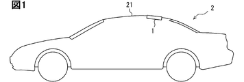
- FIG. 1 is a diagram showing a mounting position and a mounting posture of a vehicle communication device 1 on a vehicle 2.
- the vehicle communication device 1 is attached to the roof portion 21 of the vehicle 2 and used.
- the vehicle communication device 1 can be arranged at a position deviated by a predetermined amount from the central portion of the roof portion 21 of the vehicle 2 or the central portion forward or backward.
- the vehicle communication device 1 is arranged at the rear end of the upper surface of the roof portion 21 of the vehicle 2.
- the predetermined amount can be changed in the range of, for example, about 0.1 m to 0.5 m.
- the mounting position of the vehicle communication device 1 is not limited to the above, and may be near the front end of the roof portion 21.
- the upper surface of the roof portion 21 or the surface on the vehicle interior side corresponds to the mounting surface for the vehicle communication device 1.
- the vehicle communication device 1 is mounted on the vehicle 2 in a manner of being fitted into a hole provided at a predetermined position on the roof portion 21.
- the roof portion 21 of the vehicle 2 is gently inclined downward from the central portion toward the rear end portion, that is, the roof portion 21 is located downward toward the rear of the vehicle 2. It shows the form to be used.
- the vehicle 2 on which the vehicle communication device 1 is mounted is not limited to the roof-shaped vehicle 2 shown in FIG.
- the vehicle communication device 1 can be mounted on a vehicle whose outer surface shape of the roof is substantially flat.
- the vehicle communication device 1 can be mounted on vehicles having various external shapes.
- the vehicle communication device 1 can be mounted on a box-type vehicle.
- the vehicle communication device 1 can be mounted on vehicles of various categories.
- the vehicle communication device 1 can be mounted on a truck or a bus.
- the vehicle communication device 1 is configured to be able to transmit and receive radio waves of a mobile communication system using a plurality of antennas.
- the vehicle communication device 1 is configured to be able to transmit and receive radio waves in the 2.5 GHz band, which is one of the frequency bands assigned to the fifth generation (so-called 5G) mobile communication system, by MIMO system. .. MIMO is an abbreviation for multiple-input and multiple-output.
- MIMO is an abbreviation for multiple-input and multiple-output.
- As a form of communication using a plurality of antennas there are an antenna diversity method, a beamforming method, and the like, in addition to the MIMO method.
- the configuration of the present disclosure is also applicable to a configuration for performing communication such as an antenna diversity method and a beamforming method.
- the frequency band targeted for transmission / reception of the vehicle communication device 1 may be appropriately designed, and is not limited to the 2.5 GHz band.
- the operating frequency bands are 700 MHz band, 800 MHz band, 900 MHz band, 1.5 GHz band, 1.7 GHz band, 2 GHz band, 2.5 GHz band, 3.4 GHz band, 3.7 GHz band, 4.5 GHz band, and 28 GHz band. It may be a part or all of.
- the radio waves to be transmitted and received by the vehicle communication device 1 are not limited to 5G radio waves. It may be a 4G or LTE (Long Term Evolution) radio wave. In addition, it may be a radio wave for V2X communication. Radio waves in the 5.9 GHz band or 700 MHz band are used for V2X communication. Further, the vehicle communication device 1 may be configured to enable only one of transmission and reception.
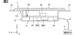
- the vehicle communication device 1 includes, for example, a circuit board 11, a housing 12 for accommodating the circuit board 11, and a cover 13.
- the circuit board 11 is a module in which various electronic components are mounted on the printed circuit board B1.
- the circuit board 11 will be described later separately.
- the direction orthogonal to the circuit board 11 corresponds to the vertical direction for the vehicle communication device 1.
- the housing 12 is formed in a shape that can accommodate the circuit board 11.
- the housing 12 is formed in a flat rectangular parallelepiped shape whose thickness direction is, for example, a direction perpendicular to the circuit board 11. That is, the housing 12 is formed in a box shape having a predetermined depth.
- the housing 12 is made of resin so as not to block radio waves.
- a fitting groove 121 for fitting with the edge portion of the hole provided in the roof portion 21 is formed on the side surface of the housing 12.
- the fitting groove 121 is formed near the upper end of the side surface of the housing 12. According to this configuration, the protrusion of the upper surface of the housing 12 with respect to the upper surface of the roof portion 21 can be suppressed.
- the fitting groove 121 is preferably provided over the entire circumference of the side surface portion in order to improve waterproofness. Of course, the fitting groove 121 may be formed only on a part of the side surface portion.
- the cover 13 is a member that covers the entire upper surface of the housing 12, and is adhered to the roof portion 21 with an adhesive.
- the cover 13 is made of resin so as not to block radio waves.
- the cover 13 plays a role of preventing water from entering the vehicle interior through a hole provided in the roof portion 21 for fitting the vehicle communication device 1. Further, the cover 13 plays a role of protecting the housing 12 and the circuit board 11 from scattered objects such as sand and hail.
- the vehicle communication device 1 is connected to the communication ECU (Electronic Control Unit) 3 via the communication cable 4, and the signals received by the vehicle communication device 1 are sequentially output to the communication ECU 3. Further, the vehicle communication device 1 converts an electric signal input from the communication ECU 3 into a radio wave and radiates it into the space. The communication ECU 3 acquires a signal received by the vehicle communication device 1 and outputs a transmission signal or transmission data to the vehicle communication device 1.
- the communication cable 4 a coaxial cable, a cable for Ethernet (registered trademark), or the like can be adopted.
- the vehicle communication device 1 and the communication ECU 3 may be configured to be connectable by wireless communication in addition to the wired connection.
- Bluetooth registered trademark
- Wi-Fi registered trademark
- ZigBee registered trademark
- the vehicle communication device 1 is attached to the vehicle so that the circuit board 11 is parallel to the roof portion 21 and the antenna mounting surface faces upward of the vehicle.
- the antenna mounting surface here refers to the surface on the circuit board 11 on which various antennas are arranged.
- the state indicated by the expression “parallel” here is not limited to perfect parallelism. It also includes the state where the inclination is about several degrees to several tens of degrees. Similarly, the expression “vertical” is not limited to a completely vertical state. It also includes a state of tilting from several degrees to several tens of degrees.
- the vehicle communication device 1 is set up, down, left and right so as to correspond to the mounting posture in the vehicle.
- FIG. 3 is a front view showing an example of a schematic configuration of the circuit board 11 according to the present embodiment.
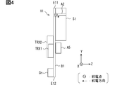
- FIG. 4 is a side view of the circuit board 11.
- the circuit board 11 includes a printed circuit board B1, antennas A1 to A5, wireless circuits TRX1 to TRX2, a vehicle connector Cn, an interface circuit Ci, a power supply circuit Cp, and the like as main components.
- ⁇ represents the wavelength of the radio wave to be transmitted and received, that is, the target wavelength.
- ⁇ / 2 and “0.5 ⁇ ” refer to half the length of the target wavelength
- ⁇ / 4" and “0.25 ⁇ ” refer to the length of one quarter of the target wavelength.
- the wavelength (that is, ⁇ ) of the 2.5 GHz radio wave in vacuum and air is about 120 mm.
- the printed circuit board B1 is, for example, a multilayer board including a plurality of conductor layers and an insulating layer. At least one inner conductor layer included in the printed circuit board B1 is configured to act as a main plate for various antennas A1 to A5.
- the main plate is a conductor plate that provides a ground potential, and is electrically connected to, for example, a ground terminal of a power supply circuit Cp, an external conductor of a coaxial cable, or a ground side wire of a power cable.
- the conductor layer as the main plate can be called a ground layer.
- the conductor layer as the main plate may be formed on the lower side surface of the substrate B1.
- the printed circuit board B1 is formed in a rectangular shape having an area on which various electronic components and the like can be mounted.
- the shape of the printed circuit board B1 is not limited to a rectangular shape, but may be a trapezoidal shape or a square shape.
- the length of the short side of the printed circuit board B1 is, for example, electrically equivalent to 0.5 ⁇ , and the length of the long side is set to correspond to 0.75 ⁇ .
- the electrical length here refers to the length considering the wavelength shortening effect of the dielectric.
- the electrical length is also called the effective length.
- the dimensions of the printed circuit board B1 described above are examples and can be changed as appropriate.
- the printed circuit board B1 corresponds to the facing board.
- the configuration of the circuit board 11 will be described by introducing the concept of a right-handed three-dimensional coordinate system having X-axis, Y-axis, and Z-axis orthogonal to each other.
- the X-axis shown in various drawings such as FIG. 3 represents the longitudinal direction of the printed circuit board B1
- the Y-axis represents the lateral direction of the printed circuit board B1
- the Z-axis represents the vertical direction.
- the direction along any one side can be the X-axis.
- the three-dimensional coordinate system including these X-axis, Y-axis, and Z-axis is a concept for explaining the configuration of the vehicle communication device 1.
- the X-axis corresponds to the left-right direction of the vehicle 2
- the Y-axis corresponds to the front-rear direction of the vehicle 2
- the Z-axis corresponds to the height direction of the vehicle 2.
- the X-axis positive direction corresponds to the vehicle right direction.
- the positive direction of the Y axis corresponds to the front of the vehicle.
- the Z-axis positive direction corresponds to the upper part of the vehicle.
- the edge portion located on the positive direction side of the Y axis is the front end portion E11 of the main board, and the edge portion located on the negative direction side of the Y axis is the rear portion of the main board. It is referred to as end E12.
- the edge portion located on the positive side of the X axis is referred to as the right end portion E13 of the main board, and the edge portion located on the negative direction side of the X axis is referred to as the left end portion E14 of the main board.
- Antennas A1 to A5, an interface circuit Ci, and a power supply circuit Cp are formed on one surface of the printed circuit board B1.
- the surface of the printed circuit board B1 and the circuit board 11 on which the antennas A1 to A5 are provided is referred to as an antenna forming surface, and the surface opposite to the antenna forming surface is referred to as a back surface.
- the antenna forming surface corresponds to a surface facing upward when mounted on a vehicle. Therefore, the antenna forming surface can also be called the upper surface.
- the back surface corresponds to the surface facing below the vehicle, in other words, toward the interior of the vehicle when mounted on the vehicle. Therefore, the back surface can also be called the lower surface.
- the wireless circuits TRX1 to TRX2 and the vehicle connector Cn are arranged on the back surface of the printed circuit board B1.
- the back surface corresponds to the back surface portion.
- the vehicle connector Cn is configured to connect the communication cable 4.
- the vehicle connector Cn is arranged on the back surface of the printed circuit board B1 with one end in the longitudinal direction aligned with the X-axis positive side end of the main board rear end E12 and in a posture along the main board rear end E12. There is.
- the vehicle connector Cn is fixed at one corner of the printed circuit board B1 in a posture in which the longitudinal direction of the vehicle connector Cn is along the longitudinal direction of the printed circuit board B1.
- the corner where the vehicle connector Cn is arranged on the printed circuit board B1 is referred to as a connector arrangement corner.
- the interface circuit Ci is a group of circuits that perform signal processing for the circuit board 11 to communicate with the communication ECU 3 via the vehicle connector Cn and the communication cable 4.
- the interface circuit Ci includes a circuit for converting a signal format, a buffer circuit for temporarily storing received data, a buffer circuit for temporarily storing transmission data, and the like.
- the interface circuit Ci can include a configuration (so-called I / O device) that converts a logical signal into an actual electrical signal in Ethernet (registered trademark), UART, or the like. In many cases, I / O devices corresponding to various communication standards are realized as chipsets (so-called PHY chips).
- the interface circuit Ci may include a PHY chip of a predetermined communication standard.
- the interface circuit Ci is arranged on the back side of the vehicle connector Cn, that is, at the corner of the connector arrangement on the antenna mounting surface of the printed circuit board B1.
- the power supply circuit Cp is a circuit module that converts the voltage supplied from the vehicle power supply into the operating voltage of each circuit and outputs it.
- the power supply circuit Cp is also arranged in the vicinity of the interface circuit Ci.
- the power supply circuit Cp is formed along the rear end portion E12 of the main board of the antenna mounting surface so as to be adjacent to the interface circuit Ci in the X-axis direction.
- This configuration corresponds to a configuration in which the power supply circuit Cp and the interface circuit Ci are arranged on the back side of the vehicle connector Cn.
- the interface circuit Ci and the power supply circuit Cp may be integrally formed. Since the height of the interface circuit Ci and the power supply circuit Cp is lower than that of the vehicle connector Cn, the side view of FIG. 4 is not shown.
- Antennas A1 to A4 are antennas for performing data communication with a radio base station constituting a mobile communication system.
- the antennas A1 to A4 are antennas for receiving, transmitting, or transmitting / receiving radio waves in the 2.5 GHz band, for example.
- Antennas A1 to A4 can also be called antennas for mobile communication.
- the radio base station is set on the ground. Therefore, it is preferable that the antennas A1 to A4 are configured to be capable of transmitting, receiving, or transmitting / receiving radio waves arriving from the horizontal direction.
- the radio base station is mainly configured to transmit and receive vertically polarized waves. Therefore, it is preferable that any one of the antennas A1 to A4 has a configuration suitable for transmitting and receiving vertically polarized waves.
- a configuration suitable for transmitting and receiving vertically polarized waves is, for example, a monopole antenna provided perpendicular to the printed circuit board B1.
- Antennas A1 to A4 are configured to operate as, for example, a monopole antenna. That is, each of the antennas A1 to A4 is configured by using a linearly formed conductor having a length electrically corresponding to ⁇ / 4. Each of the antennas A1 to A4 has a refractive shape that is bent at a right angle at a position away from the feeding point. The arrow in the figure indicates the feeding direction which is the extending direction of the antennas A1 to A4 at the feeding point. The feeding direction corresponds to the tangential direction of the antenna element at the feeding point.
- the antenna A1 is set as a receive-only antenna.
- the antenna A1 is formed in an L shape, for example, on the antenna forming surface along a corner located diagonally to the corner where the connector is installed.
- the antenna A1 has a portion along the front end portion E11 of the main board and a portion along the left end portion E14 of the main board.
- the feeding point of the antenna A1 is provided at the end portion on the X-axis positive direction side of the portion along the front end portion E11 of the main board. According to this configuration, the feeding direction of the antenna A1 is the negative direction of the X-axis.
- the configuration in which the linear antenna element is provided along the edge of the printed circuit board B1 also includes an embodiment in which a distance of less than a predetermined distance exists between the edge of the printed circuit board B1 and the antenna element.
- the predetermined distance here can be, for example, 0.1 ⁇ .
- Antenna A2 is a transmission / reception antenna.
- the antenna A1 is erected with respect to the printed circuit board B1 by using the support portion S1 at the central portion of the main substrate front end portion E11 of the antenna forming surface, for example.
- the support portion S1 is configured to support the antenna A2.
- the support portion S1 has, for example, a rectangular parallelepiped structure, and is formed by using, for example, a resin.
- the antenna A2 extends from the side surface of the rectangular parallelepiped support portion S1 along the upper surface, and has a configuration in which the antenna A2 is bent at a right angle at the edge portion of the upper surface of the support portion S1.
- the antenna A2 has an upright portion extending in the positive direction of the Z axis along the side surface of the support portion S1 and a floating section extending so as to face the antenna forming surface on the upper surface of the support portion S1. And.
- the floating section of the antenna A2 is further extended from the upper end of the upright portion in the positive direction of the X axis to the parallel portion of the X axis and from the end of the parallel portion of the X axis in the positive direction of the X axis in the negative direction of the Y axis. It is provided with an extending Y-axis parallel portion.
- the antenna A2 is configured to have a total length of ⁇ / 4.
- the feeding point is formed at the base of the upright portion, that is, on the printed circuit board B1.
- the feeding direction of the antenna A2 is the positive direction of the Z axis.
- the antenna A2 corresponds to the antenna arranged at the position closest to the wireless circuit TRX1 among the antennas A1 to A4. Further, the antenna A2 corresponds to the tallest antenna among the antennas A1 to A4.
- the antenna A2 may be provided with a stub or a short-circuit portion for matching impedance. This is because the impedance can change depending on the height of the antenna A2.
- Antenna A3 is a receive-only antenna.
- the antenna A3 is formed in an L-shape along the corner portion connecting the front end portion E11 of the main board and the right end portion E13 of the main board, for example, on the antenna forming surface.
- the antenna A3 has a portion along the front end portion E11 of the main board and a portion along the right end portion E13 of the main board.
- the feeding point of the antenna A3 is provided at the end portion on the negative direction side of the Y-axis of the portion along the right end portion E13 of the main board. According to this configuration, the feeding direction of the antenna A3 is the positive direction of the Y axis.
- Antenna A4 is a receive-only antenna.
- the antenna A4 is formed in an L-shape along a corner portion connecting the rear end portion E12 of the main board and the left end portion E14 of the main board, for example, on the antenna forming surface. That is, the antenna A4 has a portion along the rear end portion E12 of the main board and a portion along the left end portion E14 of the main board.
- the feeding point is provided at the end on the positive direction side of the Y-axis of the portion along the left end E14 of the main board. According to this configuration, the feeding direction of the antenna A4 is the negative direction of the Y axis.
- Antenna A5 is an antenna that receives a navigation signal transmitted by a navigation satellite provided in GNSS (Global Navigation Satellite System).
- the antenna A5 can also be called an antenna for satellite communication. Since the navigation satellite exists in the sky, the GNSS antenna 112 is an antenna that needs to receive radio waves arriving from above the vehicle, in other words, from the zenith direction.
- the antenna A5 is configured as, for example, a patch antenna.
- the antenna A5 as a patch antenna may be cut so that a set of diagonal portions acts as a degenerate separation element so that circularly polarized waves can be transmitted and received.
- the antenna A5 is arranged at a position deviated by a predetermined distance from the center of the printed circuit board B1 on the positive direction side of the X axis. In other words, the antenna A5 is arranged on the Y-axis negative direction side of the antenna A3.
- the above-mentioned arrangement mode corresponds to a configuration in which the antenna A5 is arranged at a position separated from the antenna A2 having a three-dimensional structure by a predetermined distance. Further, the above-mentioned arrangement mode corresponds to a configuration in which the antenna A5 is arranged closer to the antenna A3 formed in a plane than the antenna A2 having a three-dimensional structure.
- the wireless circuit TRX1 is a circuit module for receiving signals transmitted from other devices via a wireless base station and antennas A1 to A4. That is, the wireless circuit TRX1 is a circuit for executing data communication.
- the wireless circuit TRX1 includes a circuit for taking out received data by performing predetermined signal processing for the signals received by the antennas A1 to A4, and a circuit for outputting a transmission signal to the antenna A2 and transmitting it as a radio wave. That is, it includes a modulation circuit, a demodulation circuit, a detection circuit, a signal amplifier, a frequency converter, a phase adjuster, and the like.
- the wireless circuit TRX1 is electrically connected to each of the antennas A1 to A4.
- the wireless circuit TRX1 is arranged in a region located at the center of the antennas A1 to A4 on the back surface of the printed circuit board B1.
- the wireless circuit TRX1 is arranged in the center of the back surface of the printed circuit board B1.
- such a configuration corresponds to a configuration in which the wireless circuit TRX1 is arranged at positions approximately equidistant from the antennas A1, A3, and A4. Since the wireless circuit TRX1 is arranged in the center, the transmitting / receiving antenna A2 corresponds to the antenna arranged at the position closest to the wireless circuit TRX1 among the antennas A1 to A4 as described above.
- the antenna A2 which is also used for signal transmission, near the wireless circuit TRX1, signal loss in the transmission process can be suppressed.
- the wireless circuit TRX2 is a circuit for receiving and processing a signal from a satellite via the antenna A5.
- the radio circuit TRX2 is configured to function as a GNSS receiver that calculates the current position based on a signal from a positioning satellite.
- the wireless circuit TRX2 is arranged behind the antenna A5.
- the correlation value here is also referred to as a correlation coefficient. It is generally known that in a communication method using a plurality of antennas, the larger the correlation value, the worse the communication performance. That is, the smaller the correlation value is, the more preferable the parameter.
- FIG. 5 is a diagram showing a simulation model using two antennas Aa and an antenna Ab configured as a monopole antenna. Both the antenna Aa and the antenna Ab are erected in the positive direction of the Z axis, and the feeding direction is both the positive direction of the Z axis.
- the width W of the antenna Aa and the antenna Ab as individual radiating elements is set to 0.005 ⁇ .
- the height H of each of the antennas Aa and Ab is 0.25 ⁇ .
- D in FIG. 5 represents the distance between the antennas, in other words, the distance.
- the main plate Gn is set to a size sufficiently large with respect to the wavelength to be transmitted and received.
- the distance between the ante in the present disclosure corresponds to the distance of the feeding point of each antenna.
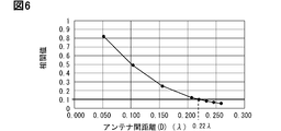
- FIG. 6 shows the simulation results of the correlation values when the distances D of the antennas Aa and Ab are changed in the above model.
- the smaller the distance between the antennas the higher the correlation value.
- the correlation value can be suppressed to 0.1 or less. Further, if the correlation value is 0.1 or less, it can be expected that sufficient communication quality can be obtained as a communication method using a plurality of antennas such as the antenna diversity method and the MIMO method.
- FIG. 6 shows that if antennas having the same feeding direction are arranged in a positional relationship in which the separation is less than 0.22 ⁇ , the correlation value becomes 0.1 or more, and the communication performance may deteriorate. ing.
- the threshold value of the antenna interval that can deteriorate the communication performance in this way is also referred to as the bond length hereafter.
- the bond length is, for example, 0.22 ⁇ .
- the bond length may be 0.25 ⁇ .
- the bond distance can be 0.175 ⁇ .
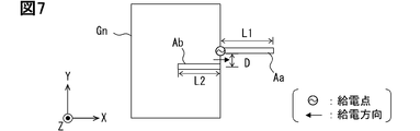
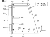
- FIGS. 7 to 10 are diagrams for explaining a simulation model using two antennas Aa and an antenna Ab configured as a monopole antenna.
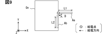
- FIG. 7 and 9 both show a simulation model including an antenna Aa formed linearly in the X-axis direction and an L-shaped antenna Ab formed so as to stand upright with respect to the main plate Gn.
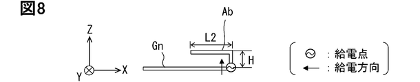
- FIG. 8 schematically shows the configuration of the antenna Ab of FIG. 7 in the XZ plane
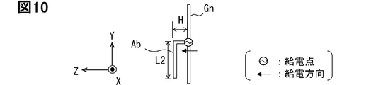
- FIG. 10 schematically shows the configuration of the antenna Ab of FIG. 9 in the YZ plane.
- L in the figure represents the length of the antenna Aa, and is set to L ⁇ / 4.
- H in the figure represents the height of the antenna Ab and is a variable.
- L2 in the figure represents the length of the portion of the antenna Ab parallel to the main plate Gn.
- the antenna Ab is configured to satisfy H + L2 ⁇ / 4.
- the simulation model shown in FIGS. 9 and 10 is referred to as an A model.
- the simulation model shown in FIGS. 9 and 10 is referred to as a B model.
- the A model corresponds to a configuration in which the antenna Ab is bent in the opposite direction to the antenna Aa.
- the B model corresponds to a configuration in which the antenna Ab is bent in a direction orthogonal to the antenna Aa. Both correspond to configurations in which the feeding directions of the antennas Aa and Ab are orthogonal to each other.
- the distance D between the antennas is set to, for example, equivalent to 0.1 ⁇ .
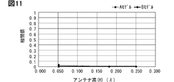
- FIG. 11 shows the simulation results of the correlation values when the height H of the antenna Ab is changed in the A model and the B model.
- the correlation value can be suppressed to 0.1 or less regardless of the height H.
- Such a tendency was the same even if the distance D of the antennas Aa and Ab was changed in the range of 0.05 ⁇ to 0.25 ⁇ . That is, if the feeding directions are orthogonal to each other, the correlation value can be suppressed to 0.1 or less even if the distance D between the antennas is equal to or less than the coupling distance.
- the correlation value between the antennas can be suppressed by performing the design based on the following design concepts (1) and (2).
- the antennas A1 to data communication 1 to Antenna A2 is the highest position in A4. That is, the antenna A2 corresponds to the antenna element arranged at the best position in the radio wave environment among the antennas A1 to A4.
- the antenna A2 at the highest position as a transmission / reception antenna, it becomes easy to secure the communication performance.
- the antenna A5 for satellite communication should be able to see the entire sky area.
- the antenna A2 tends to deteriorate the reception characteristics.
- the antenna A5 is arranged closer to the shorter A3 than the tall antenna A2. According to this configuration, it is possible to suppress the possibility of a radio wave blind spot in the antenna A5 for satellite communication.
- the radio blind spot is a direction in which the signal cannot be directly received, and is also called out of sight for the antenna.
- the feeding direction of the antenna A1 is the negative direction of the X axis
- the feeding direction of the antenna A2 is the positive direction of the Z axis
- the feeding direction of the antenna A3 is the positive direction of the Y axis
- the feeding direction of the antenna A4 is the negative direction of the Y axis.
- the feeding directions are orthogonal to each other. Specifically, the feeding directions of the antenna A1 and the antenna A2, the antenna A2 and the antenna A3, and the antenna A1 and the antenna A4 are orthogonal to each other.
- the correlation value between the two antennas can be suppressed to a predetermined value (for example, 0.1 or less) even if the distance between the antennas is less than the coupling distance. That is, it is possible to arrange them in close proximity without deteriorating the communication performance. As a result, the board size can be reduced.
- the antennas A1 to A4 for mobile communication can be arranged in close proximity. As a result, it becomes possible to accommodate a plurality of antennas A1 to A4 for mobile communication and a wireless circuit TRX1 for processing received signals by those antennas in one case.
- the vehicle communication device 1 can be miniaturized, and in particular, the height can be suppressed. Further, as the vehicle communication device 1 becomes smaller, the mountability on the vehicle 2 can be improved.
- the antennas A1 to A4 in a bent shape such as an L shape, further miniaturization becomes possible.
- the height of the vehicle communication device 1 can be reduced by forming the antenna A2, which is erected with respect to the printed circuit board B1, into a bent shape that is bent in two stages. As a result, the amount of protrusion of the vehicle communication device 1 with respect to the upper surface of the roof portion 21 can be reduced.
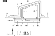
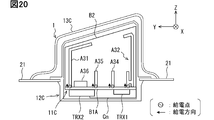
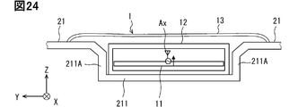
- FIG. 12 is a diagram schematically showing the overall configuration of the vehicle communication device 1 according to the second embodiment.
- 13 is a front view of the circuit board 11 in the second embodiment, and
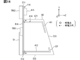
- FIG. 14 is a side view of the vehicle communication device 1 in the second embodiment.
- the external shape of the vehicle communication device 1 is formed into a streamlined shape that reduces air resistance due to traveling, that is, a so-called shark fin shape. It is at the point where it is formed in.
- the shark fin shape corresponds to a three-dimensional shape formed so that the thickness is thinner than the length in the front-rear direction and the height is gradually increased from the front end to the rear end.
- the shark fin shape can also be called a dolphin shape.
- the second embodiment can be understood as a modification of the first embodiment.
- the vehicle communication device 1 of the second embodiment includes a circuit board 11A, a housing 12A, and a cover 13A.
- the cover 13A is formed in a shark fin shape.
- the housing 12A is formed so as to accommodate a circuit board 11A including a sub-board B2 that is vertically erected with respect to the main board B1A. That is, the housing 12A also has a substantially shear fin-like shape protruding in the vehicle height direction.
- the circuit board 11A includes a main board B1A corresponding to the printed circuit board B1, a sub board B2, antennas A11 to 15, wireless circuits TRX1 to TRX2, a vehicle connector Cn, an interface circuit Ci, and a power supply circuit Cp.
- the main board B1A is a rectangular printed circuit board whose longitudinal direction is the Y-axis direction.
- the main substrate B1A is configured as a multilayer substrate including a plurality of conductor layers and an insulating layer. At least one inner conductor layer included in the main substrate B1A is configured to act as a main plate for various antennas A11 to A15.
- the length of the main board B1A in the X-axis direction is electrically set to correspond to 0.4 ⁇ , and the length in the Y-axis direction is set to correspond to 0.7 ⁇ .
- the length of the main substrate B1A in the Y-axis direction is preferably set to 0.5 ⁇ or more.
- the sub-board B2 is a plate-shaped member mounted perpendicular to the main board B1A.
- the sub-board B2 is realized by using a printed circuit board.
- the sub-board B2 may be a simple resin plate.
- the sub-board B2 is erected on the antenna mounting surface along the center line, which is a line parallel to the Y-axis through the center of the main board B1A.
- the sub-board B2 is attached to the antenna mounting surface of the printed circuit board B1 in a posture parallel to the YZ plane.
- the sub-board B2 is formed so that the height increases from the end in the positive direction of the Y-axis toward the negative direction of the Y-axis.
- the shape of the sub-board B2 may be a right-angled trapezoid or a triangle.
- the edge portion on the positive direction side of the Z axis may be formed in a curved shape.
- it is formed in a right-angled trapezoid as shown in FIG.
- the sub-board B2 corresponds to a vertical plate.
- the edge portion on the Y-axis positive direction side of the edge portions provided in the sub-board B2 will be referred to as the sub-board front end portion E21.
- the positive direction of the Y-axis corresponds to the front of the vehicle when the vehicle is mounted.
- the Y-axis negative direction corresponds to the rear of the vehicle
- the edge portion on the Y-axis negative direction side of the edge portions provided on the sub-board B2 is referred to as the sub-board rear end portion E22.
- the edge portion on the Z-axis positive direction side of the edge portions provided in the sub-board B2 is referred to as the sub-board upper end portion E23.
- the edge on the negative direction of the Z-axis is referred to as the lower end of the sub-board.
- the lower end of the sub-board corresponds to the joint with the main board B1A.
- the side surface on the negative direction side of the X-axis is referred to as the left side surface
- the side surface on the positive direction side of the X-axis is also referred to as the right side surface.
- the length of the sub-board B2 in the Y-axis direction can be appropriately set within a range smaller than the length of the main board B1A in the Y-axis direction.
- the length of the sub-board B2 in the Y-axis direction is set to 0.4 ⁇ .
- the length of the sub-board B2 in the Y-axis direction is preferably 0.22 ⁇ or more electrically.
- the length of the sub-board B2 in the Z-axis direction is configured to gradually increase in the negative direction of the Y-axis.
- the length of the front end portion E21 of the sub-board is set to a length corresponding to, for example, 0.15 ⁇ electrically.
- the length of the rear end portion E22 of the sub-board is set to a length corresponding to, for example, 0.2 ⁇ electrically. Note that these lengths are examples and can be changed as appropriate.
- the length of the end portion on the positive direction side of the Y axis may be equivalent to 0.1 ⁇ or 0.2 ⁇ .
- the rear end portion E22 of the sub-board may be formed longer than the front end portion E21 of the sub-board. From the viewpoint of suppressing the height of the vehicle communication device 1, it is preferable that the sub-board B2 is formed low.
- the vehicle connector Cn is arranged on the back surface of the main board B1A so that one end in the longitudinal direction is aligned with the rear end portion E12 of the main board and along the right end portion E13 of the main board.
- the interface circuit Ci is arranged at the back side of the vehicle connector Cn, that is, at the corner of the connector arrangement on the antenna mounting surface of the printed circuit board B1.
- the vehicle connector Cn corresponds to one of the largest components mounted on the main board B1A. By arranging such a vehicle connector Cn in a posture along the Y-axis direction, the width of the main board B1A in the X-axis direction can be suppressed. As a result, the mountability on the vehicle 2 can be improved.
- the interface circuit Ci is arranged between the right end portion E13 of the main board and the sub board B2 on the antenna mounting surface.
- the power supply circuit Cp is arranged in the vicinity of the interface circuit Ci.
- the power supply circuit Cp is arranged between the right end portion E13 of the main board and the sub board B2 on the antenna mounting surface so as to be adjacent to the interface circuit Ci in the Y-axis direction.
- the interface circuit Ci and the power supply circuit Cp are not shown in the side view of FIG.
- Antennas A11 to A14 are antennas for performing data communication with a radio base station constituting a mobile communication system.
- the antennas A11 to A14 have a configuration corresponding to the above-mentioned antennas A1 to A4.
- the antennas A11 to A14 are configured to operate as monopole antennas as in the first embodiment.
- Antenna A11 is a receive-only antenna.
- the antenna A11 is formed in an L shape, for example, on the antenna forming surface along a corner located diagonally to the corner where the connector is installed.
- the antenna A11 has a portion along the front end portion E11 of the main board and a portion along the left end portion E14 of the main board.
- the feeding point of the antenna A11 is provided at the end portion on the X-axis positive direction side of the portion along the front end portion E11 of the main board. According to this configuration, the feeding direction of the antenna A11 is the negative direction of the X-axis.
- Antenna A12 is a transmission / reception antenna.
- the antenna A12 extends from the lower end of the sub-board toward the upper end E23 of the sub-board along the rear end E22 of the sub-board.
- the antenna A12 extends perpendicular to the main board B1A.
- the antenna A12 has a configuration in which the antenna A12 is bent in the positive direction of the Y-axis so as to be along the upper end portion E23 of the sub-board near the upper end portion E23 of the sub-board.
- the antenna A12 has an upright portion extending along the rear end portion E22 of the sub-board and a connecting portion 121 extending along the upper end portion E23 of the sub-board from the joint portion with the main board B1A. And prepare.
- the antenna A12 is configured to have a total length of ⁇ / 4.
- the feeding point is formed at the base of the vertical portion, that is, at the end of the antenna A12 on the negative direction side of the Z axis. According to this configuration, the feeding direction of the antenna A12 is the positive direction of the Z axis. Further, the antenna A12 corresponds to the tallest antenna among the antennas A11 to A14.
- Antenna A13 is a receive-only antenna.
- the antenna A13 is formed in an L-shape along the corner portion connecting the front end portion E11 of the main board and the right end portion E13 of the main board, for example, on the antenna forming surface.
- the antenna A13 has a portion along the front end portion E11 of the main board and a portion along the right end portion E13 of the main board.
- the feeding point of the antenna A13 is provided at the end portion on the negative direction side of the Y-axis of the portion along the right end portion E13 of the main board.
- the feeding direction of the antenna A13 is the positive direction of the Y axis.
- the distance between the feeding point of the antenna A13 and the feeding point of the antenna A11 may be less than the coupling distance because these feeding directions are orthogonal to each other.
- Antenna A14 is a receive-only antenna.
- the antenna A14 extends from the lower end of the sub-board toward the upper end of the sub-board E23 along the front end of the sub-board E21.
- the antenna A14 extends perpendicular to the main board B1A.
- the antenna A14 has a configuration in which the antenna A14 is bent in the negative direction of the Y-axis along the upper end portion E23 of the sub-board near the upper end portion E23 of the sub-board.
- the antenna A14 has a standing portion extending along the front end portion E21 of the sub-board and a connecting portion 141 extending along the upper end portion E23 of the sub-board from the joint portion with the main board B1A.
- the antenna A14 is configured to have a total length of ⁇ / 4.
- the feeding point is formed at the end of the antenna A14 on the negative direction side of the Z axis.
- the feeding point of the antenna A14 is formed at the junction between the sub-board B2 and the main board B1A.
- the feeding direction of the antenna A14 is the positive direction of the Z axis.
- the distance between the feeding point of the antenna A14 and the feeding point of the antenna A11 may be less than the coupling distance because these feeding directions are orthogonal to each other.
- the distance between the feeding point of the antenna A14 and the feeding point of the antenna A13 may be less than the coupling distance because these feeding directions are orthogonal to each other.
- the antenna A12 and the antenna A14 are both formed on the sub-board B2, and the feeding directions are the same.
- the antenna A12 is formed along the rear end portion E22 of the sub-board
- the antenna A14 is formed along the front end portion E21 of the sub-board. Since the length of the sub-board B2 in the Y-axis direction is set to ⁇ / 4 or more, the distance between the antenna A12 and the antenna A14 is also set to 0.22 ⁇ or more. According to such a configuration, the correlation value between the antenna A12 and the antenna A14 can be suppressed to 0.1 or less.
- Antenna A15 has a configuration corresponding to antenna A5.
- the antenna A15 is arranged at the center of the main board B1A in the X-axis direction and at a position on the positive side of the sub-board B2 in the Y-axis direction. In other words, the antenna A15 is arranged between the antenna A11 and the antenna A13.
- the wireless circuit TRX1 is electrically connected to each of the antennas A11 to A14.
- the wireless circuit TRX1 is arranged on the back surface of the printed circuit board B1 at a position deviated by a predetermined amount on the X-axis negative direction side from the central portion. In other words, it is arranged between the sub-board B2 and the left end portion E14 of the main board.
- the arrangement mode is an example, and may be arranged at a position overlapping the sub-board B2 on the back surface of the printed circuit board B1. Further, it is preferable that the wireless circuit TRX1 is arranged at a position where the total value of the distances from each of the antennas A11 to A14 is minimized.
- the wireless circuit TRX1 is arranged near the antenna A12 which is also used for signal transmission.
- the wireless circuit TRX1 may be arranged at a location corresponding to the center of gravity of the feeding points of the antennas A11 to 14.
- the wireless circuit TRX2 is a circuit for receiving and processing a signal from a satellite via the antenna A15.
- the wireless circuit TRX2 is arranged behind the antenna A15.
- the L-shape here is not limited to the configuration in which the shape is bent at a right angle. Includes a configuration in which the bending angle is 30 ° to 150 °.
- the bending angle refers to the internal angle of the bent part.
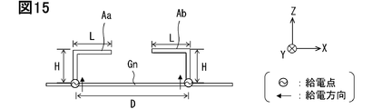
- FIG. 15 shows a simulation model including L-shaped antennas Aa and Ab formed so as to stand up against the main plate Gn.
- L in the figure represents the length of the portion of the antennas Aa and Ab parallel to the main plate Gn
- H in the figure represents the height of the antennas Aa and Ab.
- Both the antennas Aa and Ab are configured to satisfy H + L ⁇ / 4.
- the distance D between the antennas is set to, for example, equivalent to 0.23 ⁇ .
- the bending direction of the antenna Aa is the direction in which the antenna Ab is present
- the bending direction of the antenna Ab is the direction in which the antenna Aa is present. That is, the antennas Aa and Ab have a configuration in which the antennas Aa and Ab are bent toward the other side.
- the feeding directions are the same in the positive direction of the Z axis.
- FIG. 16 shows the simulation results of the correlation values when the heights H of the antennas Aa and Ab are changed while the distance D between the antennas is kept constant in the simulation model shown in FIG.
- the correlation value can be suppressed to 0.1 or less regardless of the height H.
- Such a tendency is the same in the range where the distance D between the antennas Aa and Ab is 0.22 ⁇ or more. That is, it can be seen that even if the antennas Aa and Ab are bent, the distance D between the antennas described with reference to FIGS. 5 to 6 and the correlation value and the relationship are the same.
- the correlation value is suppressed and the antenna is used for vehicles.
- the height of the communication device 1 can be suppressed.
- the feeding direction of the antenna A11 is the negative X-axis direction
- the feeding direction of the antenna A12 is the positive Z-axis direction
- the feeding direction of the antenna A13 is the positive Y-axis direction
- the feeding direction of the antenna A14 is the positive X-axis direction.
- the feeding directions of the antenna A12 and the antenna A14 are both positive in the Z axis and are the same, but the correlation value between the two antennas is 0.1 or less because the antenna spacing is equal to or longer than the bond distance. Can be maintained. That is, the risk of deterioration in communication performance can be reduced. Further, since the antennas A12 and A14 extending in the positive direction of the Z axis include a configuration in which the antennas A12 and A14 are bent in the middle, the height of the antenna and the height of the vehicle communication device 1 can be reduced without deteriorating the communication performance.
- the antenna A12 corresponds to the tallest antenna among the plurality of antennas A11 to A14 for mobile communication.
- the antenna A12 is erected with respect to the main board B1A.
- the antenna A12 is at the highest position as shown in FIG. 12, and is the best position for the radio wave environment. Therefore, by using the antenna A12 as a transmission / reception antenna, the quality of the transmission signal can be improved.
- the antenna A15 for satellite communication is arranged at a position away from the tallest antenna A12. According to such a configuration, the blind spot caused by the antenna A12 can be reduced. In addition, according to the above configuration, the same effect as that of the first embodiment is obtained.
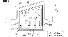
- FIG. 17 is a diagram showing a state in which the vehicle communication device 1 according to the third embodiment is attached to the roof portion.
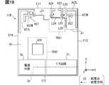
- FIG. 18 is a front view of the circuit board 11B in the third embodiment, and
- FIG. 19 is a side view of the circuit board 11B in the third embodiment.
- the third embodiment corresponds to a modification of the first embodiment.
- the vehicle communication device 1 of the third embodiment is configured to be capable of transmitting and receiving radio waves in a plurality of frequency bands.
- the vehicle communication device 1 of the third embodiment is equipped with an antenna that can transmit and receive each of a plurality of types of frequency bands.
- the frequency band is also called a band.
- the vehicle communication device 1 is configured to be capable of transmitting and receiving radio waves in three types of frequency bands: high band, middle band, and low band.
- the low band is the lowest frequency band among the three frequency bands, and can be, for example, a 1.5 GHz band.
- the middle band is the second lowest frequency band among the three frequency bands, and can be, for example, a 2.5 GHz band.
- the high band is the highest frequency band among the three frequency bands, and can be, for example, a 4.5 GHz band.
- the frequency band of each band and the number of bands to be transmitted / received can be changed as appropriate.
- the high band can be in the 3.7 GHz band.
- the wavelength of the high band radio wave is described as ⁇ H
- the wavelength of the middle band radio wave is described as ⁇ M
- the wavelength of the low band radio wave is described as ⁇ L.
- the wavelength of radio waves in a certain frequency band the wavelength of the center frequency of the frequency band can be adopted.
- the vehicle communication device 1 of the third embodiment includes a circuit board 11B, a housing 12B, and a cover 13B.
- the configuration of the housing 12B and the cover 13B the same configuration as the housing 12 and the cover 13 of the first embodiment can be adopted.
- the circuit board 11B includes a printed circuit board B1, antennas A21 to 26, wireless circuits TRX1 to TRX2, a vehicle connector Cn, an interface circuit Ci, and a power supply circuit Cp.
- FIG. 18 shows a configuration in which the Y-axis direction is set in the longitudinal direction, but the present invention is not limited to this.
- the printed circuit board B1 may be set to have a length in the X-axis direction longer than that in the Y-axis direction.
- the length of the printed circuit board B1 in the X-axis direction is set to, for example, 0.5 ⁇ L, and the length in the Y-axis direction is set to correspond to 0.6 ⁇ L.
- the dimensions of the printed circuit board B1 can be changed as appropriate.
- the vehicle connector Cn is arranged on the back surface of the printed circuit board B1 so that one end in the longitudinal direction is aligned with the right end portion E13 of the main board and along the rear end portion E12 of the main board.
- the interface circuit Ci is arranged at the back side of the vehicle connector Cn, that is, at the corner of the connector arrangement on the antenna mounting surface of the printed circuit board B1.
- the power supply circuit Cp is arranged adjacent to the interface circuit Ci.
- the power supply circuit Cp extends in the positive direction of the X-axis from the left end portion E14 of the main board of the antenna mounting surface so as to be adjacent to the interface circuit Ci in the Y-axis direction.
- the interface circuit Ci and the power supply circuit Cp are not shown in the side view of FIG. The positions of the interface circuit Ci and the power supply circuit Cp can be exchanged. Further, the interface circuit Ci and the power supply circuit Cp may be configured to be integrated or to share parts.
- Antennas A21 to A25 are antennas for performing data communication with wireless base stations constituting a mobile communication system.
- the antenna A21 is configured as a dual-band antenna dedicated to low-band and middle-band reception.
- the antenna A21 is patterned in a corner region located diagonally to the connector installation corner, for example, on the antenna forming surface.
- the antenna A21 has a configuration in which a middle band portion A21M, which is a linear element for receiving a middle band signal, and a low band portion A21L, which is a linear element for receiving a low band signal, are combined.
- the low band portion A21L and the middle band portion A21M are electrically connected at predetermined positions.
- Both the low band portion A21L and the middle band portion A21M are formed in an L shape.
- the low band portion A21L has a portion along the front end portion E11 of the main board and a portion along the left end portion E14 of the main board.
- the middle band portion A21M also has a portion parallel to the front end portion E11 of the main board and a portion parallel to the left end portion E14 of the main board.
- the middle band portion A21M is arranged inside the low band portion A21L.
- the feeding point is provided at the end of the middle band portion A21M on the positive direction side of the X axis.
- the feeding direction of the antenna A21 is the negative direction of the X-axis.
- the antenna A21 is configured to be able to receive a low band signal in cooperation with the low band portion A21L and a part of the middle band portion A21M.
- the low band portion A21L corresponds to an antenna element that shares a feeding point with the middle band portion A21M.
- Antenna A21 corresponds to the antenna located at the farthest position from the wireless circuit TRX1. Therefore, the antenna A21 has the longest line L21 from the wireless circuit TRX1 to the feeding point among the antennas A21 to A25.
- the length from the feeding point to the wireless circuit TRX1 will be abbreviated as the line length.
- Antenna A22 is a triple band antenna for both low band, middle band, and high band transmission and reception.
- the antenna A22 is erected with respect to the printed circuit board B1 by using the support portion S1 in the corner region where the front end portion E11 of the main board and the right end portion E13 of the main board are connected, for example, on the antenna forming surface.
- the support portion S1 has a rectangular parallelepiped structure and is arranged along the main board front end portion E11 and the main board right end portion E13.
- the support portion S1 is formed by using, for example, a resin or the like.
- the length of the support portion S1 in the Y-axis direction is set to, for example, 0.22 ⁇ H or more. Further, the height of the support portion S1 is set to correspond to ⁇ H / 4.
- the antenna A22 extends from the side surface of the block-shaped support portion S1 on the negative direction side of the X axis along the upper surface, and has a configuration in which the antenna A22 is bent at a right angle at the edge of the upper surface of the support portion S1.
- the antenna A22 is patterned from the side surface of the support portion S1 on the negative direction side of the X axis to the upper surface.
- the antenna A22 has a configuration in which a high band portion A22H, a middle band portion A22M, and a low band portion A22L are combined.
- the high band section A22H is configured to transmit and receive high band signals.
- the middle band portion A22M is a linear element for transmitting and receiving middle band signals.
- the low band portion A22L is a linear element for transmitting and receiving low band signals. As shown in FIGS. 18 to 19, the high band portion A22H and the middle band portion A22M, and the middle band portion A22M and the low band portion A22L are electrically connected at predetermined positions, respectively.
- the high band portion A22H is erected parallel to the Z-axis positive direction from the lower end of the support portion S1.
- the high band portion A22H is formed linearly so as to have a length of ⁇ H / 4 electrically.
- the high band portion A22H is arranged in the most negative direction on the Y axis.
- the high band portion A22H corresponds to an antenna element for high frequency.
- Both the middle band portion A22M and the low band portion A22L extend along the side surface of the support portion S1 so as to face the antenna forming surface on the vertical portion extending in the positive direction of the Z axis and the upper surface of the support portion S1. It has a floating section that is set up.
- the floating sections of the middle band portion A22M and the low band portion A22L are the X-axis parallel portion, which is a portion extending in the positive direction of the X-axis from the upper end portion of the vertical portion, and the end portion of the X-axis parallel portion on the positive direction side of the X-axis. It is provided with a Y-axis parallel portion extending from the Y-axis in the negative direction.
- the middle band portion A22M is configured to have a total length of ⁇ M / 4.
- the antenna A22 is configured to be able to transmit and receive a middle band signal by the cooperation of a part of the middle band portion A22M and the high band portion A22H.
- the low band portion A22L is configured to have a total length of ⁇ L / 4.
- the antenna A22 is configured to be able to transmit and receive low-band signals by the cooperation of the low-band portion A22L, a part of the middle-band portion A22M, and a part of the high-band portion A22H.
- the low band portion A22L and the middle band portion A22M correspond to an antenna element that shares a feeding point with the high band portion A22H. Further, the low band portion A22L corresponds to an antenna element for low frequencies.
- the feeding point is formed at the base of the upright portion of the high band portion A22H, that is, on the printed circuit board B1.
- the feeding direction of the antenna A22 is the positive direction of the Z axis.
- the antenna A22 corresponds to the antenna arranged at the position closest to the wireless circuit TRX1 among the antennas A21 to A25. Therefore, the antenna A22 has the shortest length of the line L22 from the wireless circuit TRX1 to the feeding point among the antennas A21 to A25. Further, the antenna A22 corresponds to one of the tallest antennas among the antennas A1 to A4.
- the antenna for the high band, the antenna for the middle band, and the antenna for the low band are arranged in the vicinity of the wireless circuit TRX1 in a manner of sharing the feeding point. According to this configuration, it is possible to guarantee the quality of not only the high band signal but also the relatively low frequency signal. Further, the above configuration corresponds to a configuration in which the antenna closest to the wireless circuit TRX1 is used as an antenna for transmission or transmission / reception. Since the number of transmitting antennas is smaller than that of receiving antennas, it is easy to guarantee the quality of the transmitted signal according to the configuration.
- Antenna A23 is a single band antenna for both high band transmission and reception.
- the antenna A23 is arranged on the antenna forming surface, for example, on the X-axis negative direction side of the support portion S1.
- the antenna A23 is formed in an L-shaped pattern. Specifically, the antenna A23 has a Y-axis parallel portion that is parallel to the Y-axis positive direction and an X-axis parallel portion that extends from the Y-axis positive direction end portion of the Y-axis parallel portion to the X-axis negative direction side. And prepare.
- the antenna A23 is configured to have a total length of ⁇ H / 4.
- the feeding point of the antenna A23 is provided at the end of the Y-axis parallel portion on the negative direction side of the Y-axis. According to this configuration, the feeding direction of the antenna A23 is the positive direction of the Y axis. The distance between the feeding point of the antenna A23 and the feeding point of the antenna A22 may be less than the bond distance because these feeding directions are orthogonal to each other.
- the antenna A23 corresponds to the antenna arranged second closest to the wireless circuit TRX1 among the antennas A21 to A25. Therefore, in the antenna A23, the length of the line L23 from the wireless circuit TRX1 to the feeding point is the second shortest among the antennas A21 to A25.
- Such a configuration corresponds to a configuration in which an antenna close to the wireless circuit TRX1 is used as an antenna for transmission or transmission / reception. As described above, since the number of transmitting antennas is smaller than that of receiving antennas, it is easy to guarantee the quality of the transmitted signal according to the configuration.
- Antenna A24 is a single band antenna dedicated to high band reception.
- the antenna A24 is arranged on the negative direction side of the X axis of the antenna A23.
- the antenna A24 is formed in an L-shaped pattern.
- the antenna A24 has a Y-axis parallel portion which is a portion parallel to the Y-axis positive direction and an X-axis parallel portion extending from the Y-axis positive direction end portion of the Y-axis parallel portion to the X-axis positive direction side.
- the antenna A24 is configured to have a total length of ⁇ H / 4.
- the Y-axis parallel portions of the antenna A24 and the antenna A23 are arranged apart from each other by a coupling distance or more.
- the feeding point of the antenna A24 is provided at the end of the Y-axis parallel portion on the negative direction side of the Y-axis. According to this configuration, the feeding direction of the antenna A24 is the positive direction of the Y axis. Although the feeding directions of the antenna A23 and the antenna A24 are the same, since the separation between them is equal to or longer than the bond distance, the correlation value can be suppressed to 0.1 or less.
- the antenna A24 has the second longest line L24 from the wireless circuit TRX1 to the feeding point among the antennas A21 to A25.
- the line length is shorter than that of the antenna A21 for the middle band and the low band.
- Such a configuration corresponds to a configuration in which a plurality of antennas A21 to A25 are arranged so that the line length of the high frequency antenna is shorter than that of the low frequency antenna.
- the high frequency signal has a larger line loss than the low frequency signal. According to this configuration, it becomes easy to guarantee the communication quality of the high band corresponding to a relatively high frequency.
- Antenna A25 is a single band antenna dedicated to high band reception.
- the antenna A25 extends to a position on the side surface of the support portion S1 on the negative direction side of the X axis, which is on the negative direction side of the Y axis with respect to the antenna A22. That is, the antenna A25 is erected parallel to the Z-axis positive direction from the lower end of the support portion S1.
- the antenna A25 is configured to have a total length of ⁇ H / 4.
- the high band portions A22H of the antenna A24 and the antenna A22 are arranged apart from each other by a coupling distance or more in the Y-axis direction. That is, the distance between the feeding points of the antenna A22 and the antenna A25 is equal to or larger than the coupling distance.
- the feeding point of the antenna A25 is formed on the end portion on the negative direction side of the Z axis, that is, on the printed circuit board B1. According to this configuration, the feeding direction of the antenna A25 is the positive direction of the Z axis. Although the feeding directions of the antenna A25 and the antenna A22 are the same, since the separation between them is equal to or longer than the bond distance, the correlation value can be suppressed to 0.1 or less.
- the length of the line L25 from the wireless circuit TRX1 to the feeding point is the third shortest among the antennas A21 to A25.
- the line length of the antenna A25 is shorter than that of the antenna A21 for the middle band and the low band. According to this configuration, it becomes easy to guarantee the communication quality of the high band corresponding to the relatively high frequency.
- Antenna A26 has a configuration corresponding to antenna A5.
- the antenna A26 is arranged on the antenna mounting surface on the Y-axis direction side of the power supply circuit Cp or the interface circuit Ci.
- the antenna A26 is preferably arranged at a certain distance from the antennas A22 and A25 having a three-dimensional structure provided by the support portion S1 in order to maintain a good view of the sky.
- the wireless circuit TRX1 is electrically connected to each of the antennas A21 to A25.
- the wireless circuit TRX1 is arranged on the back surface of the printed circuit board B1 at a position on the X-axis negative direction side of the antenna A22 and the antenna A25 and on the Y-axis negative direction side of the antennas A23 and A24. From another point of view, such a configuration corresponds to a configuration in which the antennas A22 to A25 corresponding to the high band are arranged around the wireless circuit TRX1. More specifically, it corresponds to a configuration in which the high band antennas A22 to A25 are arranged within a range in which the distance from the wireless circuit TRX1 is within a predetermined distance (for example, ⁇ H / 4). Further, from another viewpoint, the arrangement mode preferentially places the antennas A22 to A25 corresponding to the high band closer to the wireless circuit TRX1 than the antenna A21 for the low band corresponding to the relatively low frequency. Corresponds to the arranged configuration.
- the wireless circuit TRX1 may be arranged at a position overlapping the support portion S1 on the back surface of the printed circuit board B1. Further, it is preferable that the wireless circuit TRX1 is arranged at a position where the total value of the line lengths of the antennas A21 to A25 is minimized. The wireless circuit TRX1 may be arranged at a position corresponding to the center of gravity of the feeding points of the antennas A21 to A25. According to the above configuration, line loss can be suppressed.
- the wireless circuit TRX2 is a circuit for receiving and processing a signal from a satellite via the antenna A26.
- the wireless circuit TRX2 is arranged behind the antenna A26.
- the antennas A21 and A22 are provided as antennas capable of receiving, transmitting, or transmitting / receiving low-band signals. That is, there are two low-band antennas. Further, antennas A21 and A22 are provided as antennas capable of receiving, transmitting, or transmitting / receiving middle band signals. That is, there are two antennas for the middle band. Further, antennas A22 to A25 are provided as antennas capable of receiving, transmitting, or transmitting / receiving high-band signals. That is, as the antenna for the high band, four antennas A22 to A25 are provided.
- Such a configuration corresponds to a configuration in which the number of antennas is increased as the frequency becomes higher. It also corresponds to the configuration with the largest number of antennas corresponding to the highest frequency band. Qualitatively, as the frequency increases, the line loss tends to increase, the signal is attenuated, and the communication performance tends to deteriorate.
- the above configuration was created by paying attention to the problem, and it becomes easier to secure the communication performance by increasing the number of antennas having a higher frequency.
- the antennas A22 and A23 used for signal transmission are arranged closer to the wireless circuit TRX1 in preference to the reception-only antenna A24 having the same frequency band for transmission and reception. According to this configuration, signal loss in the transmission process can be suppressed.
- the distance between the antennas can be set to be less than the coupling distance while suppressing the correlation value to 0.1 or less. Since the feeding directions of the antenna A22 and the antenna A21 are orthogonal to each other, the distance between the antennas can be set to be less than the coupling distance while suppressing the correlation value to 0.1 or less. That is, it is possible to maintain good communication performance using the plurality of antennas while concentrating the plurality of antennas.
- the antenna A21 and the antenna A25 correspond to the antennas erected perpendicular to the printed circuit board B1.
- the antenna A25 behaves as a monopole antenna that is substantially perpendicular to the ground.
- these antennas A21 and A25 have relatively high antenna positions, the communication quality can be improved. According to the above configuration, the same effect as that of the first and second embodiments is obtained.
- the above configuration was created based on the following design concepts (3) to (6) in addition to the above-mentioned design concepts (1) and (2), and the correlation value between the antennas can be suppressed.
- the low-frequency antenna here corresponds to, for example, the above-mentioned low-band portion A22L. Further, for example, the above-mentioned high band portion A22H corresponds to the above-mentioned antenna for high frequency.
- the feeding point of the high-frequency antenna arranged in the vicinity of the wireless circuit TRX1 is shared with the low-frequency antenna.
- the low frequency antenna can also be arranged in the vicinity of the wireless circuit TRX1.
- the configuration corresponds to preferentially arranging a multi-band antenna, which is an antenna configured to operate in a plurality of frequency bands including a high frequency band, in the vicinity of the wireless circuit TRX1.
- the transmission-only or transmission / reception antennas are preferentially placed near the wireless circuit TRX1.
- the number of antennas for transmission is smaller than the number of antennas for reception, and the margin of communication performance for signal transmission is small. Therefore, the transmission loss has a great influence on the communication quality. Therefore, the quality of the transmission signal can be improved by preferentially arranging the transmission-only or transmission / reception antennas near the wireless circuit TRX1.
- An antenna that operates on the principle of a monopole antenna is erected near the wireless circuit TRX1 with respect to the printed circuit board B1, and the antenna is set as a transmission-only or transmission / reception antenna.
- Radio base stations are primarily configured to transmit vertically polarized waves.
- the antenna erected on the printed circuit board B1 behaves as a monopole antenna that is substantially perpendicular to the ground, and acts as a monopole antenna with a radio base station. It becomes easier to guarantee the communication quality.
- the design concept may include arranging the antenna for satellite communication on the printed circuit board B1 and at a position away from the conductive three-dimensional structure such as the vehicle body. Based on this, it is possible to suppress the risk of radio wave blind spots in the antenna for satellite communication.
- FIG. 20 is a diagram showing a state in which the vehicle communication device 1 according to the fourth embodiment is attached to the vehicle.
- 21 is a front view of the circuit board 11C in the fourth embodiment
- FIG. 22 is a side view of the circuit board 11C.
- the fourth embodiment corresponds to a modified example of the second embodiment. Further, the fourth embodiment corresponds to a configuration in which the second embodiment and the third embodiment are combined.
- the main difference between the fourth embodiment and the second embodiment is that the vehicle communication device 1 of the fourth embodiment is configured to be capable of transmitting and receiving a plurality of frequency bands. In other words, it is equipped with a plurality of antennas having different operating frequencies.
- the vehicle communication device 1 is configured to be able to transmit and receive radio waves in two types of frequency bands, high band and low band.
- the low band is a lower frequency band than the high band, and can be, for example, a 1.5 GHz band.
- the high band can be, for example, a 4.5 GHz band.
- the wavelength of the high band radio wave is described as ⁇ H
- the wavelength of the low band radio wave is described as ⁇ L.
- the vehicle communication device 1 of the fourth embodiment includes a circuit board 11C, a housing 12C, and a cover 13C.
- the configuration of the housing 12C and the cover 13C the same configuration as the housing 12A and the cover 13A of the second embodiment can be adopted.
- the circuit board 11C includes a main board B1A as a printed circuit board B1, a sub board B2, antennas A31 to 35, wireless circuits TRX1 to TRX2, a vehicle connector Cn, an interface circuit Ci, and a power supply circuit Cp.
- the length of the main board B1A in the X-axis direction is electrically set to correspond to 0.25 ⁇ L, and the length in the Y-axis direction is set to correspond to 0.3 ⁇ .
- the dimensions of the main substrate B1A can be changed as appropriate.
- the length of the main substrate B1A in the Y-axis direction is preferably set to 0.22 ⁇ L or more.
- the sub-board B2 is a printed circuit board mounted perpendicular to the main board B1A.
- the sub-board B2 is arranged parallel to the YZ plane on the antenna mounting surface.
- the position in the X-axis direction on the antenna mounting surface of the sub-board B2 can be, for example, a position deviated from the central portion by a predetermined distance.
- the position in the X-axis direction on the antenna mounting surface of the sub-board B2 may be a position passing through the center of the antenna mounting surface.
- the sub-board B2 is formed so that the length in the Z-axis direction increases from the end in the positive direction of the Y-axis toward the end in the negative direction of the Y-axis.
- the length of the sub-board B2 in the Y-axis direction is set to be the same as the length of the main board B1A in the Y-axis direction.
- the sub-board front end portion E21 is arranged so as to coincide with the main board front end portion E11
- the sub-board rear end portion E22 is arranged so as to coincide with the main board rear end portion E12.
- the length of the sub-board B2 in the Y-axis direction may be set shorter than the length of the main board B1A in the Y-axis direction.
- the length of the sub-board B2 in the Y-axis direction is set longer than 0.22 ⁇ L.
- the length that is, the height of the sub-board B2 in the Z-axis direction may differ between the end portion on the positive direction side of the Y-axis and the end portion on the negative direction side of the Y-axis.
- the length of the front end portion E21 of the sub-board is set to a length corresponding to, for example, 0.15 ⁇ L electrically.
- the length of the rear end portion E22 of the sub-board is set to a length corresponding to, for example, 0.2 ⁇ L electrically.
- the vehicle connector Cn is arranged on the back surface of the main board B1A so that one end in the longitudinal direction is aligned with the rear end portion E12 of the main board and along the right end portion E13 of the main board.
- the interface circuit Ci is arranged on the back side of the vehicle connector Cn.
- the interface circuit Ci is arranged between the right end portion E13 of the main board and the sub board B2 on the antenna mounting surface.
- the power supply circuit Cp is arranged in the vicinity of the interface circuit Ci.
- the power supply circuit Cp is arranged between the right end portion E13 of the main board on the antenna mounting surface and the sub board B2 so as to be adjacent to the interface circuit Ci in the Y-axis direction.
- the interface circuit Ci and the power supply circuit Cp are not shown in the side view of FIG. 22.
- the above configuration corresponds to a configuration in which the sub-board B2 is arranged adjacent to the power supply circuit Cp and the interface circuit Ci.
- Antennas A31 to A35 are antennas for performing data communication with wireless base stations constituting a mobile communication system.
- the antenna A31 is configured as a single-band antenna dedicated to low-band reception.
- the antenna A31 extends from the lower end of the sub-board toward the upper end of the sub-board E23 along the front end of the sub-board E21.
- the antenna A31 extends perpendicular to the main board B1A.
- the antenna A31 has a configuration in which the antenna A31 is bent in the negative direction of the Y-axis so as to be along the upper end portion E23 of the sub-board near the upper end portion E23 of the sub-board.
- the antenna A31 has an upright portion extending along the front end portion E21 of the sub-board from the joint portion with the main board B1A and a connecting portion 311 extending along the upper end portion E23 of the sub-board. Be prepared.
- the antenna A31 is configured to have a total length of ⁇ L / 4.
- the feeding point of the antenna A31 is formed at the base of the upright portion, that is, at the end of the antenna A31 on the negative direction side of the Z axis. According to this configuration, the feeding direction of the antenna A31 is the positive direction of the Z axis.
- the antenna A31 corresponds to the antenna arranged at the farthest position from the wireless circuit TRX1 among the antennas A31 to A35. Therefore, the antenna A31 has the longest length of the line L35 from the wireless circuit TRX1 to the feeding point among the antennas A31 to A35. However, since the signal corresponding to the antenna A31 has a relatively low frequency, the line loss is relatively small.
- Antenna A32 is a double band antenna for both low band and high band transmission and reception.
- the antenna A32 is patterned so as to be along the rear end portion E22 of the sub-board, for example, on the left side surface of the sub-board B2.
- the antenna A32 has a configuration in which a high band portion A32H for transmitting and receiving a high band and a low band portion A32L which is a linear element for transmitting and receiving a low band signal are combined.
- the high band portion A32H and the low band portion A22L are electrically connected at predetermined positions.
- the low band portion A32L extends from the lower end portion of the sub-board toward the upper end portion E23 of the sub-board along the rear end portion E22 of the sub-board. In other words, the low band portion A32L is erected perpendicular to the main substrate B1A. Further, the low band portion A32L has a configuration in which the low band portion A32L is bent in the positive direction of the Y axis so as to be along the sub-board upper end portion E23 in the vicinity of the sub-board upper end portion E23.
- the low band portion A32L is a standing portion extending along the rear end portion E22 of the sub-board and a connecting portion extending along the upper end portion E23 of the sub-board from the joint portion with the main board B1A. 321 and.
- the low band portion A32L is configured to have a total length of ⁇ L / 4.
- the high band portion A32H is formed linearly on the Y-axis positive direction side of the low band portion A32L in a posture parallel to the standing portion of the low band portion A32L. In other words, the high band portion A32H is erected perpendicular to the main substrate B1A.
- the high band portion A32H is electrically set to a length of ⁇ H / 4.
- the feeding point of the antenna A32 is formed at the root of the high band portion A32H, that is, at the end of the antenna A32 on the negative direction side of the Z axis. According to this configuration, the feeding direction of the antenna A32 is the positive direction of the Z axis.
- the antenna A32 is configured to be able to transmit and receive low-band signals by the cooperation of a part of the low-band portion A32L and the high-band portion A32H.
- the low band portion A32L corresponds to an antenna element that shares a feeding point with the high band portion A32H.
- Both the antenna A31 and the antenna A32 are formed on the sub-board B2, and the feeding directions are the same.
- the antenna A32 is formed along the rear end portion E22 of the sub-board, while the antenna A31 is formed along the front end portion E21 of the sub-board. Since the length of the sub-board B2 in the Y-axis direction is set to 0.22 ⁇ L or more, the distance between the antenna A32 and the antenna A31 is also set to 0.22 ⁇ L or more. According to such a configuration, the correlation value between the antenna A32 and the antenna A31 can be suppressed to 0.1 or less.
- the antenna A32 corresponds to the antenna arranged at the position closest to the wireless circuit TRX1 among the antennas A31 to A35 as described later. Therefore, the antenna A32 has the shortest length of the line L32 from the wireless circuit TRX1 to the feeding point among the antennas A31 to A35. Therefore, it corresponds to the antenna with the smallest line loss. Further, the antenna A32 corresponds to one of the tallest antennas among the antennas A31 to A35. Therefore, the antenna A32 corresponds to an antenna arranged at a position and attitude having the best radio wave environment on the vehicle mounting path. According to the configuration in which the antenna A32 is used as both low-band and high-band transmission / reception antennas, it becomes easy to guarantee the quality of communication using a plurality of antennas.
- the configuration of the antenna A32 corresponds to a configuration in which the antenna for the high band and the antenna for the low band are arranged in the vicinity of TRX1 of the wireless circuit in a mode in which the feeding point is shared. According to this configuration, it is possible to guarantee the quality of not only the high band signal but also the low band signal.
- the antenna A32 corresponds to an antenna arranged so as to satisfy the ideas (3) to (6).
- Antenna A33 is a single band antenna for both high band transmission and reception.
- the antenna A33 is arranged along the rear end portion E12 of the main board.
- the antenna A33 is linear and, for example, patterned so as to have a length of ⁇ H / 4 electrically.
- the feeding point is provided at the end on the positive direction side of the X axis. According to this configuration, the feeding direction of the antenna A33 is the negative direction of the X-axis.
- the feeding direction is orthogonal to the antenna A32, which is the other antenna closest to the antenna A33. Therefore, the distance between the feeding point of the antenna A33 and the feeding point of the antenna A32 may be less than the coupling distance. That is, the antenna A33 may be arranged closer to the sub-board B2 than the position shown in the figure. Further, the extending direction of the antenna A33 may be parallel to the Y axis. For example, it may be arranged along the left end portion E14 of the main board. In that case, the feeding direction is the Y-axis positive direction or the negative direction. Even when the feeding direction of the antenna A33 is the positive or negative direction of the Y axis, the feeding direction is orthogonal to other antennas such as the antenna A32, so that the correlation value between them can be suppressed to 0.1 or less. ..
- the antenna A33 corresponds to the antenna arranged second closest to the wireless circuit TRX1 among the antennas A31 to A35. Therefore, in the antenna A33, the length of the line L33 from the wireless circuit TRX1 to the feeding point is the second shortest among the antennas A31 to A35. Therefore, it corresponds to the antenna with the second smallest line loss.
- the antenna A33 corresponds to an antenna satisfying the above-mentioned design concepts (3) and (5).
- Antenna A34 is a single band antenna dedicated to high band reception.
- the antenna A34 extends from the lower end of the sub-board along the Z-axis positive direction at a position 0.22 ⁇ H or more on the Y-axis positive direction side from the high band portion A32H of the antenna A32.
- the antenna A34 extends perpendicular to the main board B1A.
- the antenna A34 is linear and is configured to have a length of ⁇ H / 4.
- the feeding point of the antenna A34 is formed at the end on the negative direction side of the Z axis. According to this configuration, the feeding direction of the antenna A34 is the positive direction of the Z axis.
- the antenna A32 and the antenna A34 have the same feeding direction, but the distance between the feeding points is 0.22 ⁇ H or more, so that the correlation value can be suppressed to 0.1 or less.
- the antenna A34 corresponds to the antenna arranged third closest to the wireless circuit TRX1 among the antennas A31 to A35. Therefore, in the antenna A34, the length of the line L34 from the wireless circuit TRX1 to the feeding point is the third shortest among the antennas A31 to A35. However, the antenna A34 is erected with respect to the main board B1A, and the antenna posture when attached to the vehicle is a posture suitable for receiving radio waves from the radio base station.
- the antenna A34 corresponds to an antenna arranged so as to satisfy the above-mentioned design concepts (3) and (6).
- Antenna A35 is a single band antenna dedicated to high band reception.
- the antenna A35 extends from the lower end of the sub-board along the Z-axis positive direction at a position 0.22 ⁇ H or more on the Y-axis positive direction side from the antenna A34.
- the antenna A35 extends perpendicular to the main board B1A.
- the antenna A35 is linear and is configured to have a length of ⁇ H / 4.
- the feeding point of the antenna A35 is formed at the end on the negative direction side of the Z axis. According to this configuration, the feeding direction of the antenna A35 is the positive direction of the Z axis.
- the antenna A34 and the antenna A35 have the same feeding direction, but the distance between the feeding points is 0.22 ⁇ H or more, so that the correlation value can be suppressed to 0.1 or less.
- the above-mentioned antenna A35 corresponds to the antenna arranged second far from the wireless circuit TRX1 among the antennas A31 to A35. However, it is closer to the wireless circuit TRX1 than the low-band antenna A31.
- Such a configuration corresponds to a configuration in which the high-band antenna A35 is preferentially arranged near the radio circuit TRX1 over the low-band antenna A31.
- the antenna A35 is erected with respect to the main board B1A, and the antenna posture when attached to the vehicle is a posture suitable for receiving radio waves from the radio base station.
- the antenna A35 corresponds to an antenna arranged so as to satisfy the above-mentioned design concepts (3) and (6).
- the antenna A36 has a configuration corresponding to the antenna A5.
- the antenna A36 is arranged at an arbitrary position on the antenna mounting surface of the main board B1A in a region on the negative direction side of the X axis with respect to the sub board B2. For example, it is arranged at a position on the negative direction side of the X-axis and the side in the Y-axis direction with respect to the center of the main board B1A.
- the antenna A36 may be arranged at the center of the sub-board B2 in the negative direction of the X-axis in the negative direction of the Y-axis. According to such a configuration, the distance from the first and second tallest antennas A31 and A32 among the antennas A31 to A35 can be increased, and the blind spot for the antenna A36 can be suppressed.
- the wireless circuit TRX1 is electrically connected to each of the antennas A31 to A35.
- the wireless circuit TRX1 is arranged on the back surface of the printed circuit board B1 on the negative X-axis side of the antenna A32 and A34 and on the positive X-axis side of the antenna A33. That is, the wireless circuit TRX1 is arranged between the antenna A32 and the antenna A33.
- the antennas A32 to A34 are arranged in the vicinity region of the wireless circuit TRX1.
- the vicinity region of the wireless circuit TRX1 refers to, for example, a range in which the distance from the wireless circuit TRX1 is within a predetermined distance (for example, ⁇ H / 4).
- the wireless circuit TRX1 may be arranged on the back surface of the printed circuit board B1 at a position overlapping with the sub-board B2. Further, it is preferable that the wireless circuit TRX1 is arranged at a position where the total value of the line lengths of the antennas A31 to A35 is minimized. The wireless circuit TRX1 may be arranged at a position corresponding to the center of gravity of the feeding points of the antennas A31 to A35. According to these configurations, line loss can be suppressed.
- the wireless circuit TRX2 is a circuit for receiving and processing a signal from a satellite via the antenna A36.
- the wireless circuit TRX2 is arranged behind the antenna A36.
- the antennas A31 and A32 are provided as antennas capable of receiving, transmitting, or transmitting / receiving low band signals. That is, there are two low-band antennas. Further, antennas A32 to A35 are provided as antennas capable of receiving, transmitting, or transmitting / receiving high-band signals. That is, as the antenna for the high band, four antennas A32 to A35 are provided.
- Such a configuration corresponds to a configuration in which more high-band antennas are installed than low-band antennas.
- the higher the frequency the larger the line loss, and the communication performance tends to deteriorate.
- the above configuration was created by paying attention to the problem, and it is possible to improve the communication performance of the high band by installing a relatively large number of antennas for the high band.
- the antennas A32 and A33 which are also used for signal transmission, are preferentially arranged near the wireless circuit TRX1. According to this configuration, it is possible to suppress the loss at the time of signal transmission.
- the feeding directions of the antenna A32 and the antenna A33 are orthogonal to each other. Therefore, even if the distance between the antennas is set to be less than the bond length, the correlation value between the two antennas can be suppressed to 0.1 or less. That is, it is possible to maintain good communication performance using a plurality of antennas. Since the feeding directions of the antenna A33 and the antenna A34 are also orthogonal to each other, the distance between the antennas can be set to be less than the coupling distance while suppressing the correlation value to 0.1 or less. As a result, the vehicle communication device 1 can be miniaturized.
- the antennas A31, A32, A34, and A35 correspond to antennas erected perpendicular to the printed circuit board B1.
- these antennas behave as monopole antennas that are generally perpendicular to the ground. That is, it functions as an antenna that receives vertically polarized waves and has directivity in all directions in the horizontal direction.
- these antennas A31, A32, A34, and A35 correspond to antennas arranged at a higher position than the antenna A33. According to this configuration, it becomes easy to guarantee the communication quality.
- the vehicle communication device 1 may be provided with a patch antenna, an inverted F antenna, and a loop antenna as antennas for mobile communication.
- the feeding direction in the flat plate antenna corresponds to the extending direction of the radiating element at the feeding point.
- the present invention is not limited to this.
- the vehicle communication device 1 includes a plurality of antennas for V2X communication
- the above design concepts (1) to (6) can be applied to determine the arrangement mode of those antennas.
- a part or all of the above design concepts (1) to (6) may be applied to determine the arrangement mode of the plurality of antennas corresponding to the plurality of applications.
- the antenna A1 may be used as a Bluetooth antenna
- the antennas A2 to 3 may be used as a 4G antenna
- the antenna A4 may be used as a Wi-Fi antenna.
- the back surface of the printed circuit board B1 corresponds to the surface on the vehicle interior side.
- An antenna module for Bluetooth and / or Wi-Fi may be arranged on the back surface of the printed circuit board B1.
- the vehicle communication device 1 can provide a function for carrying out wireless communication with a smartphone or the like brought into the vehicle interior by the user.
- the main board B1A is located under the roof portion 21, and only the configuration related to the sub-board B2 is provided. May be mounted so as to be located above the roof portion 21.
- the configuration related to the sub-board B2 includes an antenna provided on the sub-board B2 and a housing for accommodating the sub-board B2. According to such a mounting mode, the size of the hole provided in the roof portion 21 can be suppressed.
- the sub-board B2 projecting upward from the roof portion 21 is configured to be protected by the housing 12 and the cover 13.
- the protruding portion 122 protruding laterally from the upper surface of the housing 12 may be fixed to the roof portion 21 with an adhesive, a screw, or the like.
- a hole portion for fitting the vehicle communication device 1 is provided in the roof portion 21, and the vehicle communication device 1 is fitted in the hole portion.
- a recess 211 may be provided in the roof portion 21 of the vehicle 2, and the vehicle communication device 1 may be fixed in the recess 211.
- Various methods such as screwing and adhesives can be used as the fixing method.
- the transmission / reception antenna Ax in the central portion of the printed circuit board B1 or the main board B1A.
- the transmission / reception antenna Ax is arranged at the edge of the substrate B1
- the blind spot for the transmission / reception antenna Ax becomes relatively large due to the metal constituting the step portion 211A of the recess 211.
- the transmission / reception antenna Ax is arranged in the central portion of the printed circuit board B1 or the main board B1A, the blind spot for the transmission / reception antenna Ax can be suppressed, and the communication performance can be easily ensured.
- the transmission / reception antenna Ax is erected on the printed circuit board B1 or the main board B1A based on the above design concept.
- the transmission / reception antenna Ax shown in FIG. 24 corresponds to the above-mentioned antennas A2, A12, A22, A32 and the like.
- the antenna element may be patterned on the inner upper surface portion of the housing 12. According to this configuration, since the antenna can be arranged at the highest position in the apparatus, the blind spot caused by the step portion 211A of the recess 211 can be reduced. It should be noted that such a vehicle communication device 1 may be configured such that the end portion of the antenna element arranged on the housing 12 side comes into contact with the feeding point provided on the printed circuit board B1. For example, a resin block having a height that abuts on the antenna element arranged on the inner upper surface portion of the housing 12 may be arranged on the printed circuit board B1, and a feeding point may be arranged on the upper surface portion of the resin block.
- the vehicle communication device 1 may be configured by using only a part of the design concepts (1) to (6).
- the vehicle communication device 1 can be configured based on the design concepts (3) to (6).
- Antennas A1, A3-4, A11, A11, A13, A21, A23-24, and A33 correspond to parallel feeding antennas. Further, the antennas A2, A12, A14, A22, A25, A31, A32, A34, and A35 correspond to vertical feeding antennas.
- Antennas A2, A12, A22, A23, and A33 correspond to transmission / reception antennas. Further, the antennas A1, A3 to 4, A11, A13 to A14, A21, A24 to A25, A31, and A34 to A35 correspond to reception-only antennas. Antennas A5, A15, A26, and A36 correspond to satellite antennas.
- the high band or middle band corresponds to the second frequency band.
- the high band is regarded as the second frequency band
- at least one of the middle band and the low band corresponds to the first frequency band.
- the low band is regarded as the first frequency band
- at least one of the high band and the middle band corresponds to the second frequency band.
- antennas A32 to A35 and A42 to A45 correspond to antennas for the second frequency.
- the antennas A31 and A41 correspond to the first frequency antenna.
- Antennas A31, A32, and A42 correspond to multi-band antennas
- antennas A33 to A35, and A41, A43 to A45 correspond to single-band antennas. Double-band antennas and triple-band antennas correspond to multi-band antennas.
- the present disclosure also includes the following various configurations.
- the antenna that is the farthest from the wireless circuit is a vehicle communication device that is not the antenna with the highest operating frequency band.
- the antenna that is the farthest from the wireless circuit is the receive-only antenna, which is a communication device for vehicles.
- a multi-band antenna (A22, A32) configured to be operable in a plurality of frequency bands and a single band antenna (A23 to A25, A31, A33 to A35) configured to be operable in one frequency band.
- the antenna with the longest electrical distance from the wireless circuit is a single band antenna, which is a communication device for vehicles.
- a multi-band antenna (A22, A32) configured to be operable in a plurality of frequency bands and a single band antenna (A23 to A25, A31, A33 to A35) configured to be operable in one frequency band.
- a multi-band antenna (A22, A32) configured to be operable in a plurality of frequency bands and a single band antenna (A23 to A25, A31, A33 to A35) configured to be operable in one frequency band.
- the antenna element located closest to the wireless circuit is a multi-band antenna, which is a communication device for vehicles.
- a vehicle communication device configured to be used by being attached to a hole provided in the roof of a vehicle.
- a vehicle communication device configured to be used by being attached to a recess (211) provided in a vehicle roof.
- the above-mentioned plurality of antenna elements are all vehicle communication devices in which a pattern is formed in a region in contact with the edge of the printed circuit board. According to this configuration, the antenna spacing can be increased and the correlation value can be further reduced.
Landscapes
- Engineering & Computer Science (AREA)
- Computer Networks & Wireless Communication (AREA)
- Signal Processing (AREA)
- Physics & Mathematics (AREA)
- Astronomy & Astrophysics (AREA)
- Aviation & Aerospace Engineering (AREA)
- General Physics & Mathematics (AREA)
- Variable-Direction Aerials And Aerial Arrays (AREA)
- Details Of Aerials (AREA)
- Support Of Aerials (AREA)
- Transceivers (AREA)
Priority Applications (3)
| Application Number | Priority Date | Filing Date | Title |
|---|---|---|---|
| CN202180046102.5A CN115917878A (zh) | 2020-07-01 | 2021-06-24 | 车辆用通信装置 |
| DE112021003552.5T DE112021003552T5 (de) | 2020-07-01 | 2021-06-24 | Fahrzeugkommunikationsvorrichtung |
| US18/075,635 US20230096365A1 (en) | 2020-07-01 | 2022-12-06 | Vehicular communication device |
Applications Claiming Priority (2)
| Application Number | Priority Date | Filing Date | Title |
|---|---|---|---|
| JP2020-114416 | 2020-07-01 | ||
| JP2020114416A JP2022012537A (ja) | 2020-07-01 | 2020-07-01 | 車両用通信装置 |
Related Child Applications (1)
| Application Number | Title | Priority Date | Filing Date |
|---|---|---|---|
| US18/075,635 Continuation US20230096365A1 (en) | 2020-07-01 | 2022-12-06 | Vehicular communication device |
Publications (1)
| Publication Number | Publication Date |
|---|---|
| WO2022004561A1 true WO2022004561A1 (ja) | 2022-01-06 |
Family
ID=79315995
Family Applications (1)
| Application Number | Title | Priority Date | Filing Date |
|---|---|---|---|
| PCT/JP2021/024022 Ceased WO2022004561A1 (ja) | 2020-07-01 | 2021-06-24 | 車両用通信装置 |
Country Status (5)
| Country | Link |
|---|---|
| US (1) | US20230096365A1 (enExample) |
| JP (1) | JP2022012537A (enExample) |
| CN (1) | CN115917878A (enExample) |
| DE (1) | DE112021003552T5 (enExample) |
| WO (1) | WO2022004561A1 (enExample) |
Cited By (1)
| Publication number | Priority date | Publication date | Assignee | Title |
|---|---|---|---|---|
| WO2024176855A1 (ja) * | 2023-02-24 | 2024-08-29 | エイターリンク株式会社 | マルチ・アンテナおよび受電装置 |
Families Citing this family (4)
| Publication number | Priority date | Publication date | Assignee | Title |
|---|---|---|---|---|
| JP7631785B2 (ja) * | 2020-12-21 | 2025-02-19 | 株式会社Soken | 車両側ユニット及び位置関係特定システム |
| KR20240175425A (ko) * | 2023-06-13 | 2024-12-20 | 현대모비스 주식회사 | 내장 안테나 |
| WO2025134534A1 (ja) * | 2023-12-19 | 2025-06-26 | 株式会社クボタ | 作業車両 |
| DE102024201315A1 (de) * | 2024-02-13 | 2025-08-14 | Continental Automotive Technologies GmbH | Vorrichtung für ein Kraftfahrzeug zum Verbinden mit einer Tachographeneinheit und System |
Citations (4)
| Publication number | Priority date | Publication date | Assignee | Title |
|---|---|---|---|---|
| US20070279304A1 (en) * | 2006-05-30 | 2007-12-06 | Guy-Aymar Chakam | Antenna module for a motor vehicle |
| JP2009033742A (ja) * | 2007-07-04 | 2009-02-12 | Toshiba Corp | アンテナ装置 |
| US7786937B1 (en) * | 2005-09-27 | 2010-08-31 | Comant Industries, Inc. | Multi-operational combination aircraft antennas |
| WO2014109397A1 (ja) * | 2013-01-10 | 2014-07-17 | 旭硝子株式会社 | Mimoアンテナおよび無線装置 |
Family Cites Families (2)
| Publication number | Priority date | Publication date | Assignee | Title |
|---|---|---|---|---|
| DE102012208303B4 (de) | 2012-05-16 | 2014-05-15 | Continental Automotive Gmbh | Antennenmodul mit Sende- und Empfangsantennenelement |
| JP2020114416A (ja) | 2020-03-24 | 2020-07-30 | 株式会社三洋物産 | 遊技機 |
-
2020
- 2020-07-01 JP JP2020114416A patent/JP2022012537A/ja active Pending
-
2021
- 2021-06-24 DE DE112021003552.5T patent/DE112021003552T5/de not_active Withdrawn
- 2021-06-24 WO PCT/JP2021/024022 patent/WO2022004561A1/ja not_active Ceased
- 2021-06-24 CN CN202180046102.5A patent/CN115917878A/zh not_active Withdrawn
-
2022
- 2022-12-06 US US18/075,635 patent/US20230096365A1/en not_active Abandoned
Patent Citations (4)
| Publication number | Priority date | Publication date | Assignee | Title |
|---|---|---|---|---|
| US7786937B1 (en) * | 2005-09-27 | 2010-08-31 | Comant Industries, Inc. | Multi-operational combination aircraft antennas |
| US20070279304A1 (en) * | 2006-05-30 | 2007-12-06 | Guy-Aymar Chakam | Antenna module for a motor vehicle |
| JP2009033742A (ja) * | 2007-07-04 | 2009-02-12 | Toshiba Corp | アンテナ装置 |
| WO2014109397A1 (ja) * | 2013-01-10 | 2014-07-17 | 旭硝子株式会社 | Mimoアンテナおよび無線装置 |
Cited By (1)
| Publication number | Priority date | Publication date | Assignee | Title |
|---|---|---|---|---|
| WO2024176855A1 (ja) * | 2023-02-24 | 2024-08-29 | エイターリンク株式会社 | マルチ・アンテナおよび受電装置 |
Also Published As
| Publication number | Publication date |
|---|---|
| CN115917878A (zh) | 2023-04-04 |
| US20230096365A1 (en) | 2023-03-30 |
| DE112021003552T5 (de) | 2023-05-25 |
| JP2022012537A (ja) | 2022-01-17 |
Similar Documents
| Publication | Publication Date | Title |
|---|---|---|
| WO2022004561A1 (ja) | 車両用通信装置 | |
| US11509053B2 (en) | Dual broadband antenna system for vehicles | |
| US9685695B2 (en) | Antenna system and antenna unit | |
| EP3096397B1 (en) | Window glass for vehicle and glass antenna | |
| US9343806B2 (en) | Antennas integrated in shield can assembly | |
| US9653787B2 (en) | Antenna system for a vehicle | |
| US20250132506A1 (en) | Antenna device | |
| US9379430B2 (en) | Multiband antenna | |
| US20220190489A1 (en) | Highly-integrated vehicle antenna configuration | |
| JPWO2015019904A1 (ja) | アンテナ装置 | |
| WO2009142031A1 (ja) | 2周波アンテナ | |
| JP5413103B2 (ja) | アンテナ装置 | |
| CN105789820A (zh) | 天线结构及具有该天线结构的无线通信装置 | |
| CN107017455A (zh) | 天线装置 | |
| KR101945070B1 (ko) | 차량용 내장형 통합 안테나 모듈 | |
| KR20120068102A (ko) | 유리창 부착형 통합 외장형 안테나 | |
| US9831545B2 (en) | Antenna device | |
| US9160057B2 (en) | Unsymmetrical dipole antenna | |
| US11721886B1 (en) | Vehicle antenna capable of operating in multiple frequency ranges and automobile antenna device | |
| EP4318798A1 (en) | Antenna device | |
| TWI661610B (zh) | 薄型天線結構 | |
| US10243269B2 (en) | Antenna | |
| EP4568018A1 (en) | Antenna assembly, signal transmission apparatus, and vehicle | |
| US9059518B2 (en) | Antenna for wireless apparatus | |
| JP6402154B2 (ja) | アンテナ装置及び車載用アンテナ装置 |
Legal Events
| Date | Code | Title | Description |
|---|---|---|---|
| 121 | Ep: the epo has been informed by wipo that ep was designated in this application |
Ref document number: 21833130 Country of ref document: EP Kind code of ref document: A1 |
|
| 122 | Ep: pct application non-entry in european phase |
Ref document number: 21833130 Country of ref document: EP Kind code of ref document: A1 |