WO2022004319A1 - 情報処理装置、情報処理方法、及びプログラム - Google Patents
情報処理装置、情報処理方法、及びプログラム Download PDFInfo
- Publication number
- WO2022004319A1 WO2022004319A1 PCT/JP2021/021998 JP2021021998W WO2022004319A1 WO 2022004319 A1 WO2022004319 A1 WO 2022004319A1 JP 2021021998 W JP2021021998 W JP 2021021998W WO 2022004319 A1 WO2022004319 A1 WO 2022004319A1
- Authority
- WO
- WIPO (PCT)
- Prior art keywords
- container
- image
- display
- cells
- information processing
- Prior art date
- Legal status (The legal status is an assumption and is not a legal conclusion. Google has not performed a legal analysis and makes no representation as to the accuracy of the status listed.)
- Ceased
Links
Images








Classifications
-
- G—PHYSICS
- G06—COMPUTING OR CALCULATING; COUNTING
- G06T—IMAGE DATA PROCESSING OR GENERATION, IN GENERAL
- G06T7/00—Image analysis
- G06T7/0002—Inspection of images, e.g. flaw detection
- G06T7/0012—Biomedical image inspection
-
- G—PHYSICS
- G06—COMPUTING OR CALCULATING; COUNTING
- G06T—IMAGE DATA PROCESSING OR GENERATION, IN GENERAL
- G06T7/00—Image analysis
- G06T7/0002—Inspection of images, e.g. flaw detection
- G06T7/0012—Biomedical image inspection
- G06T7/0014—Biomedical image inspection using an image reference approach
- G06T7/0016—Biomedical image inspection using an image reference approach involving temporal comparison
-
- G—PHYSICS
- G06—COMPUTING OR CALCULATING; COUNTING
- G06F—ELECTRIC DIGITAL DATA PROCESSING
- G06F3/00—Input arrangements for transferring data to be processed into a form capable of being handled by the computer; Output arrangements for transferring data from processing unit to output unit, e.g. interface arrangements
- G06F3/14—Digital output to display device ; Cooperation and interconnection of the display device with other functional units
-
- G—PHYSICS
- G06—COMPUTING OR CALCULATING; COUNTING
- G06F—ELECTRIC DIGITAL DATA PROCESSING
- G06F3/00—Input arrangements for transferring data to be processed into a form capable of being handled by the computer; Output arrangements for transferring data from processing unit to output unit, e.g. interface arrangements
- G06F3/14—Digital output to display device ; Cooperation and interconnection of the display device with other functional units
- G06F3/147—Digital output to display device ; Cooperation and interconnection of the display device with other functional units using display panels
-
- G—PHYSICS
- G06—COMPUTING OR CALCULATING; COUNTING
- G06T—IMAGE DATA PROCESSING OR GENERATION, IN GENERAL
- G06T5/00—Image enhancement or restoration
- G06T5/50—Image enhancement or restoration using two or more images, e.g. averaging or subtraction
-
- G—PHYSICS
- G06—COMPUTING OR CALCULATING; COUNTING
- G06V—IMAGE OR VIDEO RECOGNITION OR UNDERSTANDING
- G06V10/00—Arrangements for image or video recognition or understanding
- G06V10/40—Extraction of image or video features
- G06V10/56—Extraction of image or video features relating to colour
-
- G—PHYSICS
- G06—COMPUTING OR CALCULATING; COUNTING
- G06V—IMAGE OR VIDEO RECOGNITION OR UNDERSTANDING
- G06V20/00—Scenes; Scene-specific elements
- G06V20/60—Type of objects
- G06V20/69—Microscopic objects, e.g. biological cells or cellular parts
- G06V20/695—Preprocessing, e.g. image segmentation
-
- G—PHYSICS
- G09—EDUCATION; CRYPTOGRAPHY; DISPLAY; ADVERTISING; SEALS
- G09G—ARRANGEMENTS OR CIRCUITS FOR CONTROL OF INDICATING DEVICES USING STATIC MEANS TO PRESENT VARIABLE INFORMATION
- G09G5/00—Control arrangements or circuits for visual indicators common to cathode-ray tube indicators and other visual indicators
- G09G5/14—Display of multiple viewports
-
- G—PHYSICS
- G01—MEASURING; TESTING
- G01N—INVESTIGATING OR ANALYSING MATERIALS BY DETERMINING THEIR CHEMICAL OR PHYSICAL PROPERTIES
- G01N15/00—Investigating characteristics of particles; Investigating permeability, pore-volume or surface-area of porous materials
- G01N15/10—Investigating individual particles
- G01N2015/1006—Investigating individual particles for cytology
-
- G—PHYSICS
- G01—MEASURING; TESTING
- G01N—INVESTIGATING OR ANALYSING MATERIALS BY DETERMINING THEIR CHEMICAL OR PHYSICAL PROPERTIES
- G01N15/00—Investigating characteristics of particles; Investigating permeability, pore-volume or surface-area of porous materials
- G01N15/10—Investigating individual particles
- G01N15/14—Optical investigation techniques, e.g. flow cytometry
- G01N2015/1486—Counting the particles
-
- G—PHYSICS
- G06—COMPUTING OR CALCULATING; COUNTING
- G06T—IMAGE DATA PROCESSING OR GENERATION, IN GENERAL
- G06T2207/00—Indexing scheme for image analysis or image enhancement
- G06T2207/10—Image acquisition modality
- G06T2207/10056—Microscopic image
-
- G—PHYSICS
- G06—COMPUTING OR CALCULATING; COUNTING
- G06T—IMAGE DATA PROCESSING OR GENERATION, IN GENERAL
- G06T2207/00—Indexing scheme for image analysis or image enhancement
- G06T2207/20—Special algorithmic details
- G06T2207/20212—Image combination
- G06T2207/20224—Image subtraction
-
- G—PHYSICS
- G06—COMPUTING OR CALCULATING; COUNTING
- G06T—IMAGE DATA PROCESSING OR GENERATION, IN GENERAL
- G06T2207/00—Indexing scheme for image analysis or image enhancement
- G06T2207/30—Subject of image; Context of image processing
- G06T2207/30004—Biomedical image processing
- G06T2207/30024—Cell structures in vitro; Tissue sections in vitro
-
- G—PHYSICS
- G06—COMPUTING OR CALCULATING; COUNTING
- G06T—IMAGE DATA PROCESSING OR GENERATION, IN GENERAL
- G06T2207/00—Indexing scheme for image analysis or image enhancement
- G06T2207/30—Subject of image; Context of image processing
- G06T2207/30242—Counting objects in image
-
- G—PHYSICS
- G09—EDUCATION; CRYPTOGRAPHY; DISPLAY; ADVERTISING; SEALS
- G09G—ARRANGEMENTS OR CIRCUITS FOR CONTROL OF INDICATING DEVICES USING STATIC MEANS TO PRESENT VARIABLE INFORMATION
- G09G2354/00—Aspects of interface with display user
-
- G—PHYSICS
- G09—EDUCATION; CRYPTOGRAPHY; DISPLAY; ADVERTISING; SEALS
- G09G—ARRANGEMENTS OR CIRCUITS FOR CONTROL OF INDICATING DEVICES USING STATIC MEANS TO PRESENT VARIABLE INFORMATION
- G09G2380/00—Specific applications
- G09G2380/08—Biomedical applications
Definitions
- the technology of this disclosure relates to an information processing device, an information processing method, and a program.
- antibody drugs have been attracting attention. Unlike conventional small molecule drugs, antibody drugs are made of complex proteins and the like, so it is difficult to artificially synthesize them. Therefore, antibody drugs are produced by inserting a gene corresponding to a desired human protein into cells such as CHO (Chinese Hamster Ovary) cells, producing the desired protein by the function of the cell, and then extracting and purifying the protein. Manufactured.
- CHO Choinese Hamster Ovary
- a single cell cloning technique for generating a cell population derived from a single cell by seeding and culturing one cell into which a gene has been inserted into each well (culture container) of a well plate is known. There is.
- the single cell cloning technique improves the homogeneity of the cells that produce the antibody, thereby improving the quality of the antibody drug produced.
- the monochromeality is determined by visually observing an image of a well as a culture container (hereinafter referred to as a container image) by an inspector.
- the examiner counts the number of cells in the well by observing the container image.
- the monochromeality for the cell population is guaranteed.
- Monochromaticity determination needs to be performed on, for example, 3000 wells per project for producing an antibody. Visually checking all such a large number of container images is a heavy burden on the inspector.
- the well contains a medium, debris (dead cells, cell debris, dust, etc.) or scratches on the well. Therefore, a large number of structures are imaged in one container image. Will be done. Therefore, it is not easy for the inspector to make a monochromeity determination based on one container image, and the load on the inspector is large.
- the technique of the present disclosure is intended to provide an information processing device, an information processing method, and a program capable of reducing the burden on the inspector in determining monochromeity.
- the information processing apparatus of the present disclosure is an information processing apparatus that controls display to display a container image of an image of a container in which cells are seeded on a display, and includes at least one processor.
- the processor acquires two or more container images captured at different dates and times for the same container, and displays the acquired two or more container images on the display so as to be identifiable that the imaging dates and times are different.
- the processor includes a first container image taken before the cells are seeded, a second container image taken on the day the cells are seeded, a third container image taken the day after the cells are seeded, and the cells. It is preferable to acquire two or more images from the fourth container image taken in the culture process two days after the seeding as a container image.
- the processor can identify that the imaging date and time are different by displaying each of the two or more container images by changing the color of the frame.
- the processor can identify different imaging dates and times by displaying the number of days elapsed since the cells were seeded in association with each of the two or more container images.
- the processor displays two or more container images at positions according to the number of days elapsed since the cells were seeded so that it can be identified that the imaging date and time are different.
- the processor synchronizes display of two or more container images.
- the processor creates a difference image from the two container images and displays the created difference image on the display.
- the processor includes a first container image taken before the cells are seeded, a second container image taken on the day the cells are seeded, a third container image taken the day after the cells are seeded, and the cells. It is preferable to create a difference image from two images selected from the fourth container images taken in the culture process two days after the seeding.
- the processor creates a difference image by taking a difference between the first container image and the second container image, the third container image, or the fourth container image.
- the processor creates a difference image after correcting the positional deviation for the two container images.
- the processor corrects the misalignment based on the shape of the container in the container image or the scratch on the container.
- the processor receives the input information input from the input operation unit and selects two or more container images to be displayed on the display based on the input information.
- the processor acquires the container image captured at different dates and times for the same container as the one container image displayed on the display, and displays the acquired container image together with the container image displayed on the display. It is preferable to display on.
- the information processing method of the present disclosure is an information processing method for displaying a container image of a container in which cells are seeded on a display, and two or more container images of the same container taken at different dates and times.
- the acquired two or more container images are displayed on the display so as to be identifiable that the imaging dates and times are different.
- the program of the present disclosure is a program for causing a computer to execute a process of displaying a container image of a container in which cells are seeded on a display, and acquires two or more container images of the same container taken at different dates and times. Then, the computer is made to execute a process of displaying the acquired two or more container images on the display so as to be identifiable that the imaging dates and times are different.
- an information processing device an information processing method, and a program capable of reducing the load on the inspector in determining monochromeity.
- FIG. 1 schematically shows the judgment support system 2.
- the determination support system 2 is a system that supports "monochromality determination" in which an inspector visually determines whether or not the cell population formed in the well as a culture vessel is derived from a single cell. Monochromaticity determination is made by the examiner based on the image of the well at the time the cells were seeded.
- a cell population is a mass of a plurality of cells formed by division of seeded cells, and is also referred to as a colony.
- the determination support system 2 includes an image pickup device 3 and an information processing device 4.
- the information processing device 4 is composed of a computer.
- a display 5, a keyboard 6, a mouse 7, and the like are connected to the information processing apparatus 4.
- the keyboard 6 and the mouse 7 constitute an input operation unit 8 for the user to input information.
- the input operation unit 8 also includes a touch panel and the like.
- the image pickup device 3 is, for example, a phase-contrast microscope, and optically takes an image of a well plate 10 in which cells are seeded and cultured as an image pickup target.
- the light source and the like for illuminating the image pickup target are not shown.
- a plurality of wells 11 are formed on the well plate 10.
- the well plate 10 for example, a "96-well plate” in which 96 wells 11 are formed is used.
- Each well 11 is a culture vessel in which one cell is seeded.
- a “24-well plate” in which 24 wells 11 are formed is shown as the well plate 10.
- the well 11 is an example of a container according to the technique of the present disclosure.
- Cell seeding is performed by dispensing droplets 13 into each well 11 using a pipette 12 or the like from a reservoir containing a medium solution containing cells.
- the droplet 13 contains cells 20.
- the cell 20 is, for example, a CHO cell that produces an antibody.
- a gene corresponding to a desired human protein is inserted into the cell 20.
- the image pickup apparatus 3 takes an image of each well 11 of the well plate 10 as an image pickup target. For example, the image pickup apparatus 3 focuses on the bottom of the well 11 to perform an image pickup.
- the cells 20 are seeded in the well 11, the cells 20 are imaged by the image pickup apparatus 3 in a state of being settled at the bottom of the medium solution in the well 11.
- the image of the well 11 (hereinafter referred to as a container image) WP captured by the image pickup device 3 is transmitted to the information processing device 4, respectively.
- the seeded cells 20 are imaged on the container image WP.
- FIG. 2 shows the types of container image WP captured by the image pickup device 3.
- the imaging device 3 performs imaging before seeding the cells 20 in the well 11, and then performs imaging on the day when the cells 20 are seeded and after the day after the cells 20 are seeded.
- the image of the well 11 taken before seeding the cells 20 is referred to as a first container image WP1.
- the image of the well 11 taken on the day when the cells 20 are seeded is referred to as a second container image WP2.
- the image of the well 11 taken the day after the cells 20 are seeded (that is, one day later) is referred to as a third container image WP3.
- the image of the well 11 taken in the culture process two days after the seeding of the cells 20 (that is, two days later) is referred to as a fourth container image WP4.
- the image of the well 11 taken 7 days after the day when the cells 20 are seeded is referred to as the fourth container image WP4.
- a plurality of fourth container images WP4 may be acquired by performing an image of the well 11 every time a certain time elapses from the day when the cells 20 are seeded. ..
- FIG. 2 schematically shows container images WP1 to WP4 in the case where the cell population 20A formed as a result of seeding only one cell 20 in one well 11 has monoclonality.
- the lower part of FIG. 2 schematically shows container images WP1 to WP4 in the case where the cell population 20A formed as a result of erroneously seeding two cells 20 in one well 11 does not have monoclonality.
- FIG. 3 schematically shows an example of the first container image WP1. Since the first container image WP1 is an image of the well 11 before seeding the cells 20, the cells 20 are not shown. Further, since the first container image WP1 is an image captured by the well 11 having the scratch 21, for example, only the scratch 21 is shown.
- FIG. 4 schematically shows an example of the second container image WP2. Since the second container image WP2 is an image of the well 11 taken on the day when the cells 20 are seeded, for example, the second container image WP2 shows the debris 22 and the debris 22 contained in the medium in addition to the seeded cells 20.
- the scratch 21 of the well 11 is imaged.
- the debris 22 contains dead cells, cell debris, dust and the like.
- the debris 22 and the scratches 21 of the well 11 may be present in large numbers in one well 11.
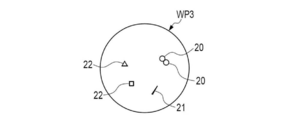
- FIG. 5 schematically shows an example of the third container image WP3. Since the third container image WP3 is an image of the well 11 taken on the day after the cells 20 are seeded, for example, the third container image WP3 is an image of two cells 20 divided by cell division. Further, in the third container image WP3, the scratches 21 of the debris 22 and the well 11 are imaged in the same manner as in the second container image WP2.
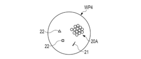
- FIG. 6 schematically shows an example of the fourth container image WP4. Since the fourth container image WP4 is an image obtained by imaging the well 11 two days after the seeding of the cells 20, for example, in the third container image WP3, a cell population 20A formed by repeating division of the cells 20 is contained. It is imaged. Further, in the fourth container image WP4, the scratches 21 of the debris 22 and the well 11 are imaged in the same manner as in the second container image WP2.
- FIG. 7 shows an example of an image pickup operation by the image pickup device 3.
- the image pickup operation of the image pickup apparatus 3 is controlled by the information processing apparatus 4.
- the image pickup apparatus 3 sequentially images a plurality of wells 11 formed on the well plate 10 one by one. Specifically, the image pickup apparatus 3 generates a container image WP by taking an image of each well 11 while sequentially changing the image pickup region 3A.
- Ancillary information includes the date and time of imaging, plate ID (identification), and well position.
- the imaging date and time is information regarding the date and time when the well 11 was imaged.
- the plate ID is identification information that identifies each well plate 10.
- the well position is the position information of the well 11 in the well plate 10. For example, in the well position, the position in the vertical direction is represented by an alphabet and the position in the horizontal direction is represented by a number. Well positions are represented by a combination of letters and numbers.
- the plate ID is obtained, for example, by reading the barcode attached to the well plate 10 with a barcode reader (not shown).
- the image pickup device 3 takes an image of the well plate 10 at a date and time instructed by the information processing device 4.
- the image pickup apparatus 3 generates an image file F for each well 11 in the well plate 10 and transmits the image file F to the information processing apparatus 4.
- FIG. 8 shows the hardware configuration of the information processing apparatus 4.
- the information processing device 4 includes a CPU (Central Processing Unit) 30, a storage device 31, and a communication unit 32, which are interconnected via a bus line 33. Further, the above-mentioned display 5 and the input operation unit 8 are connected to the bus line 33.
- a CPU Central Processing Unit
- the CPU 30 is an arithmetic unit that realizes various functions by reading out the program 31A and various data (not shown) stored in the storage device 31 and executing processing.
- the CPU 30 is an example of a processor according to the technique of the present disclosure.
- the storage device 31 includes, for example, a RAM (RandomAccessMemory), a ROM (ReadOnlyMemory), a storage device, or the like.
- the RAM is, for example, a volatile memory used as a work area or the like.
- the ROM is, for example, a non-volatile memory such as a flash memory for holding the program 31A and various data.
- the storage device is, for example, an HDD (Hard Disk Drive) or an SSD (Solid State Drive).
- the storage stores an OS (Operating System), an application program, image data, various data, and the like.
- the communication unit 32 is a network interface that controls transmission of various information via a network such as LAN (Local Area Network) or WAN (Wide Area Network).
- the display 5 displays various screens.
- the information processing device 4 receives input of an operation instruction from the input operation unit 8 through various screens.
- FIG. 9 shows the functional configuration of the information processing apparatus 4.
- the function of the information processing apparatus 4 is realized by the CPU 30 executing a process based on the program 31A.
- the information processing apparatus 4 includes a main control unit 40, an image pickup control unit 41, an acquisition unit 42, a display screen generation unit 43, a display control unit 44, and an aggregation unit 45.
- the main control unit 40 controls each unit in the information processing device 4 based on the input information 8A input from the input operation unit 8.
- the image pickup control unit 41 controls the image pickup operation of the image pickup apparatus 3 based on the control from the main control unit 40.
- the acquisition unit 42 acquires the image file F output from the image pickup apparatus 3, and inputs the acquired image file F to the display screen generation unit 43.
- the display screen generation unit 43 generates a display screen 50 for displaying the container image WP on the display 5 based on the image file F.
- the display control unit 44 causes the display 5 to display the display screen 50 generated by the display screen generation unit 43 based on the control from the main control unit 40.
- the display screen 50 is an image that identifiablely displays two or more container image WPs captured at different dates and times for the same well 11 with different imaging dates and times.
- “different date and time” means that at least the time is different. That is, the "two or more container image WPs captured at different dates and times” includes two or more container image WPs on the same day but at different times.
- the display control unit 44 displays the display screen 50 as a GUI (Graphical User Interface) so that the inspector can operate the display screen 50 by using the input operation unit 8.
- GUI Graphic User Interface
- the tabulation unit 45 receives the monochromeity determination result CR input from the input operation unit 8 via the main control unit 40, and aggregates the received determination result CR. Further, the totaling unit 45 generates the totaling result AR by totaling the determination result CR for each well plate 10.
- the display control unit 44 causes the display 5 to display the aggregation result AR generated by the aggregation unit 45.
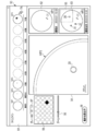
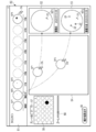
- FIG. 10 shows an example of a display screen 50 displayed on the display 5.
- the display screen 50 shown in FIG. 10 shows a display screen 50 generated based on the first container image WP1, the second container image WP2, the third container image WP3, and the fourth container image WP4.
- the inspector can make a monochromeity determination using the display screen 50.
- the display screen 50 has a first display area 51, a second display area 52, a third display area 53, and a fourth display area 54.
- the first display area 51 is a so-called timeline display area in which two or more container image WPs are displayed at positions according to the number of days elapsed since the cells 20 were seeded.
- the first container image WP1, the second container image WP2, the third container image WP3, and the fourth container image WP4 are displayed on the timeline in the first display area 51.
- the number of days elapsed since the cells 20 were seeded is displayed in association with each container image WP.
- the second display area 52 and the third display area 53 are areas for displaying one image selected from the first container image WP1, the second container image WP2, the third container image WP3, and the fourth container image WP4, respectively. Is.
- the second display area 52 and the third display area 53 are arranged adjacent to each other so that two container image WPs having different imaging times can be compared.
- the imaging time of the container image WP is displayed in the second display area 52 and the third display area 53, respectively.
- the inspector can select the container image WP to be displayed in the second display area 52 and the third display area 53 by an operation using the input operation unit 8.
- the first container image WP1 before sowing is displayed in the second display area 52
- the second container image WP2 on the day of sowing is displayed in the third display area 53.
- the fourth display area 54 is an area in which a part of the container image WP is partially enlarged and displayed. Specifically, the image included in the enlargement target area 55 set in the second display area 52 or the third display area 53 is enlarged and displayed in the fourth display area 54.
- the inspector can set the enlargement target area 55 by the operation using the input operation unit 8. In the example shown in FIG. 10, the enlargement target area 55 is set in the third display area 53 on which the second container image WP2 is displayed.
- the zoom slider 56 as a zoom operation unit is displayed on the display screen 50.
- the inspector can change the zoom magnification of the image displayed in the fourth display area 54 by sliding the zoom slider 56 using the input operation unit 8.
- a selection operation unit 57 for selecting the plate ID and a selection operation unit 58 for selecting the well position are displayed.
- the inspector can select a desired plate ID by operating the selection operation unit 57 using the input operation unit 8.
- a desired well position can be selected by operating the selection operation unit 58 using the input operation unit 8.
- the container image WP of the well 11 corresponding to the well position selected by the selection operation unit 58 is displayed on the display screen 50.
- the aggregation result display button 59 for displaying the above-mentioned aggregation result AR is displayed.
- the inspector can display the aggregation result AR on the display 5 by operating the aggregation result display button 59 using the input operation unit 8.
- the cursor 7A operated by the mouse 7 (see FIG. 1) included in the input operation unit 8 is displayed.
- the inspector can perform various selection operations by operating the mouse 7 using the cursor 7A.
- FIG. 11 shows an example of the selection operation of the container image WP to be displayed in the second display area 52 and the third display area 53.
- the inspector moves the cursor 7A by operating the mouse 7 to select a desired container image WP from two or more container image WPs displayed in the first display area 51.
- the inspector moves the selected container image WP to the second display area 52 or the third display area 53 by performing a so-called drag-and-drop operation.
- the first container image WP1 is selected from the first display area 51 and displayed in the second display area 52
- the second container image WP2 is selected from the first display area 51 to be displayed in the second display area 52.
- An example of displaying in is shown.
- the inspector selects any two container image WPs having different imaging dates and times from the two or more container image WPs displayed in the first display area 51, and sets the second display area 52 and the third display area 53. Can be displayed in.
- the inspector can efficiently determine the monochrome nature by comparing two container image WPs displayed in the second display area 52 or the third display area 53 with different imaging dates and times.
- the examiner visually determines whether or not the debris 22 is a cell as well as the cells 20. Need to be done. Therefore, when the monochromeity determination is performed based on one container image WP, all the debris 22 captured by the container image WP must be visually confirmed, which is a heavy burden on the inspector.
- the inspector can make a monochromeity determination while comparing arbitrary two container image WPs having different imaging dates and times. For example, the inspector compares the first container image WP1 before sowing (see FIG. 3) with the second container image WP2 (see FIG. 4) on the day of sowing, so that the wound 21 of the well 11 and the cells 20 and It can be easily distinguished from the debris 22.
- the inspector can discriminate between the wound 21 and the debris 22 and the cells 20 by comparing the second container image WP2 on the day of sowing with the third container image WP3 (see FIG. 5) on the day after sowing. It can be done easily. Furthermore, by comparing the second container image WP2 and the third container image WP3, the inspector was not imaged because it did not settle to the bottom of the well 11 on the day of sowing, and settled by the day after sowing. By doing so, the imaged cells 20 can be found. In addition, the examiner can also find cells 20 and the like that were not imaged because they overlapped with the debris 22 on the day of sowing by comparing the second container image WP2 and the third container image WP3. .
- the inspector can compare the second container image WP2 on the day of seeding with the fourth container image WP4 (see FIG. 6) in the culture process to obtain dead cells that look like cells 20. It is possible to easily distinguish between the debris 22 and the cell population 20A formed as a result of cell division. The same determination can be made by comparing the third container image WP3 on the day after sowing with the fourth container image WP4 in the culture process.
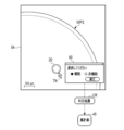
- FIG. 12 shows an example of an input interface for inputting a determination result CR as to whether or not the inspector is a cell.
- the display control unit 44 causes the selection box 60 as a GUI to be displayed in the fourth display area 54 in response to an operation using the input operation unit 8 of the inspector.
- the inspector selects whether the object is a cell or a non-cell by using the input operation unit 8 based on the selection box 60. For example, the inspector selects whether each of the cells 20 and the debris 22 imaged in the second container image WP2 on the day of sowing is a cell or a non-cell.
- the determination result CR as to whether or not the cell is a cell is input to the above-mentioned aggregation unit 45.
- the cell population 20A formed in the well 11 is derived from a single cell and has a monoclonality. Is determined.
- the examiner discriminates the cell 20, the debris 22, and the wound 21 of the well 11 by comparing two or more container image WPs as described above, and then determines whether or not the object is a true cell. Can be determined. Therefore, the load on the inspector in the monochromeity determination is reduced.
- the inspector confirms the shape of each object one by one while moving the focus of the microscope for each object existing in each well of a large number of well plates. I had to do some work.
- all the wells in the well plate are imaged at once to acquire the container image WP.
- the captured container image WP is preferably a two-dimensional image.
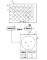
- FIG. 13 shows a display example of the aggregation result AR by the display control unit 44.
- each well 11 of the well plate 10 is "single cell", "two or more cells", or "no cell".
- the display mode shown in FIG. 13 is a so-called heat map, and the user can visually grasp the number and position of the wells 11 in which a single cell is seeded.
- the aggregation result AR is not limited to the heat map, and the cell unity or the number of cells may be listed in a table format for each well 11.
- the main control unit 40 determines whether or not there is an instruction to start imaging from the input operation unit 8 (step S10).
- the main control unit 40 determines that the instruction to start imaging has been given (step S10: YES)
- the main control unit 40 causes the image pickup apparatus 3 to perform an image pickup operation via the image pickup control unit 41 (step S11).
- the acquisition unit 42 acquires the image file F output from the image pickup apparatus 3 (step S12).
- the main control unit 40 determines whether or not there is a display instruction of the imaging result from the input operation unit 8 (step S13). If there is no display instruction (step S13: NO), the main control unit 40 returns the process to step S10.
- the inspector gave an image pickup start instruction using the input operation unit 8 at an appropriate date and time such as before sowing, on the day of sowing, the day after sowing, and the day after sowing, so that the image pickup device 3 was imaged at a different date and time.
- the above image file F is output.
- the main control unit 40 determines that the display instruction of the imaging result has been given (step S13: YES)
- the main control unit 40 causes the display screen generation unit 43 to generate the display screen 50 (step S14).
- the main control unit 40 displays the display screen 50 on the display 5 via the display control unit 44, as shown in FIG. 10 (step S15).
- the inspector can appropriately select the container image WP to be displayed in the second display area 52 and the third display area 53 of the display screen 50 (see FIG. 11).
- the inspector compares the container images WP displayed in the second display area 52 and the third display area 53, discriminates the scratches 21 of the cells 20, the debris 22, and the well 11, and then the second container image. For each object in WP2, it is determined whether or not it is a true cell (see FIG. 12).
- the main control unit 40 determines whether or not the determination result CR has been input by the inspector using the input operation unit 8 (step S16).
- the main control unit 40 determines that the determination result CR has been input (step S16: YES)
- the main control unit 40 outputs the determination result CR to the aggregation unit 45 (step S17).
- the main control unit 40 determines whether or not the inspector has instructed to display the aggregation result AR by operating the aggregation result display button 59 (see FIG. 10) using the input operation unit 8 (step). S18). If there is no display instruction (step S18: NO), the main control unit 40 returns the process to step S16. For example, the inspector operates the aggregation result display button 59 after inputting the determination result CR based on the second container image WP2 corresponding to each well 11 included in one well plate 10.
- the aggregation unit 45 aggregates the determination result CR to generate the aggregation result AR (step S19). Then, the main control unit 40 displays the aggregation result AR on the display 5 via the display control unit 44, as shown in FIG. 13 (step S20). The inspector can decide whether or not to continue the culture for each well 11 based on the aggregated result AR.
- the first modification is a modification relating to the display form of the display screen 50.
- FIG. 15 shows a display screen 50 according to the first modification.
- a frame 70 is provided in each of the container image WPs, and the frame 70 is displayed in different colors according to the imaging date and time.
- the difference in color of the frame 70 is represented by the difference in hatching.
- the frame 70 of the container image WP displayed in the first display area 51, the second display area 52, and the third display area 53 is displayed in the same color for those having the same imaging date and time. As a result, the inspector can intuitively recognize the difference in the imaging date and time.
- the shape of the frame 70 is circular in this modification, it is not limited to the circular shape and may be another shape such as a rectangle.
- the second modification is a modification relating to the selection of the container image WP to be displayed on the display screen 50.
- FIG. 16 shows a display screen 50 according to a second modification.
- the container image WP to be displayed in the second display area 52 or the third display area 53 can be selected by the drag and drop operation.
- the container image WP to be displayed in the second display area 52 or the third display area 53 can be selected by the selection box 80 as the GUI.
- the container image WP imaged at a different imaging date and time from the second container image WP2 is selected and displayed in the third display.
- the situation to be displayed in the area 53 is shown.
- the inspector can display the container image WP corresponding to the selected imaging date and time in the third display area 53 by operating the input operation unit 8 based on the selection box 80 to select the imaging date and time.
- the container image WP displayed in the third display area 53 is an image corresponding to the same well plate 10 and the same well 11 as the second container image WP 2 displayed in the second display area 52.
- the imaging date and time is displayed in the selection box 80, but the present invention is not limited to this, and the number of days elapsed from the sowing date may be displayed and the number of elapsed days may be selectable.
- the third modification is a modification relating to the fourth display area 54 (see FIG. 10) of the display screen 50.
- FIG. 17 shows a display screen 50 according to a third modification.
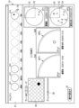
- the enlargement target area 55 set in either the second display area 52 or the third display area 53 is reflected in the other.
- the fourth display area 54 instead of the fourth display area 54, the first enlarged display area 54A and the second enlarged display area 54B are displayed so as to be adjacent to each other.
- the image included in the enlarged target area 55 set in the second display area 52 is enlarged and displayed.
- the image included in the enlarged target area 55 set in the third display area 53 is enlarged and displayed.
- the inspector can change the position or size of the enlargement target area 55 set in the second display area 52 or the third display area 53 by using the input operation unit 8.
- the other enlargement target area 55 is changed in conjunction with the change.
- the images displayed in the first enlarged display area 54A and the second enlarged display area 54B are changed in conjunction with the change of the enlarged target area 55.
- the zoom slider 56 the zoom magnification of the image displayed in the first magnified display area 54A and the second magnified display area 54B is changed in conjunction with this zoom operation.
- the synchronized display means that the operation for one image is applied to the other image as well.
- FIG. 18 shows an example of an operation for changing the enlargement target area 55.
- the enlargement target area 55 is set in the corresponding position of the second display area 52.
- the first enlarged display area 54A a portion included in the enlarged target area 55 of the first container image WP1 displayed in the second display area 52 is enlarged and displayed.
- the second enlarged display area 54B a portion included in the enlarged target area 55 of the second container image WP2 displayed in the third display area 53 is enlarged and displayed.
- the enlargement target area 55 set in the third display area 53 moves in conjunction with this movement. Then, in conjunction with the movement of the enlargement target area 55, the images displayed in the first enlarged display area 54A and the second enlarged display area 54B are changed.
- the number of the container image WPs to be synchronized is not limited to two and may be three or more.
- FIG. 19 shows a display screen 50 according to a fourth modification.
- the display screen 50 is provided with a difference image display area 90 instead of the fourth display area 54 (see FIG. 10).
- the difference image DP is displayed in the difference image display area 90.
- the difference image DP is an image obtained by subtracting the first container image WP1 from the second container image WP2 displayed in the third display area 53 to the second display area 52.
- the difference image generation unit 91 illustrated in FIG. 20 is provided in the display screen generation unit 43.
- the difference image generation unit 91 generates a difference image DP by subtracting the other from one of the two input container image WPs.
- the scratch 21 of the well 11 can be removed by subtracting the first container image WP1 from the second container image WP2 to generate a difference image DP.
- the difference image generation unit 91 takes a difference between the first container image WP1 and the second container image WP2, the third container image WP3, or the fourth container image WP4 for the purpose of removing the scratch 21 of the well 11. Is preferable.
- a position shift correction unit 92 that performs position shift correction for the two container image WPs may be provided before the difference image generation unit 91 performs the difference image generation process.
- the misalignment correction unit 92 corrects the misalignment based on the shape of the well 11 captured in the container image WP or the scratch 21 of the well 11. For example, the misalignment correction unit 92 compares the first container image WP1 and the second container image WP2, and corrects the position of the second container image WP2.
- the misalignment correction unit 92 supplies the two container image WPs after the misalignment correction to the difference image generation unit 91.
- the misalignment correction unit 92 may perform misalignment correction by a method such as rigid transformation.
- the hardware configuration of the computer constituting the information processing device 4 can be modified in various ways.
- the information processing apparatus 4 may be composed of a plurality of computers separated as hardware for the purpose of improving processing capacity and reliability.
- a processing unit that executes various processes such as a main control unit 40, an image pickup control unit 41, an acquisition unit 42, a display screen generation unit 43, a display control unit 44, and an aggregation unit 45.
- various processors include CPU30, which is a general-purpose processor that executes software (program 31A) and functions as various processing units, and circuits after manufacturing FPGAs (Field Programmable Gate Arrays) and the like.
- Dedicated electricity which is a processor with a circuit configuration specially designed to execute specific processing such as programmable logic device (PLD), ASIC (Application Specific Integrated Circuit), which is a processor whose configuration can be changed. Circuits etc. are included.
- One processing unit may be composed of one of these various processors, or may be a combination of two or more processors of the same type or different types (for example, a combination of a plurality of FPGAs and / or a CPU). It may be configured in combination with FPGA). Further, a plurality of processing units may be configured by one processor.
- one processor is configured by a combination of one or more CPUs and software, as represented by a computer such as a client and a server.
- the processor functions as a plurality of processing units.
- SoC System On Chip
- the various processing units are configured by using one or more of the above-mentioned various processors as a hardware-like structure.
- an electric circuit in which circuit elements such as semiconductor elements are combined can be used.
Landscapes
- Engineering & Computer Science (AREA)
- Theoretical Computer Science (AREA)
- Physics & Mathematics (AREA)
- General Physics & Mathematics (AREA)
- General Health & Medical Sciences (AREA)
- Health & Medical Sciences (AREA)
- Nuclear Medicine, Radiotherapy & Molecular Imaging (AREA)
- Computer Vision & Pattern Recognition (AREA)
- Quality & Reliability (AREA)
- Radiology & Medical Imaging (AREA)
- Medical Informatics (AREA)
- Human Computer Interaction (AREA)
- General Engineering & Computer Science (AREA)
- Multimedia (AREA)
- Life Sciences & Earth Sciences (AREA)
- Biomedical Technology (AREA)
- Molecular Biology (AREA)
- Computer Hardware Design (AREA)
- Apparatus Associated With Microorganisms And Enzymes (AREA)
Priority Applications (3)
| Application Number | Priority Date | Filing Date | Title |
|---|---|---|---|
| JP2022533792A JPWO2022004319A1 (https=) | 2020-07-02 | 2021-06-09 | |
| EP21833871.3A EP4177333A4 (en) | 2020-07-02 | 2021-06-09 | INFORMATION PROCESSING DEVICE, INFORMATION PROCESSING METHOD, AND PROGRAM |
| US18/146,245 US20230131555A1 (en) | 2020-07-02 | 2022-12-23 | Information processing device, information processing method, and program |
Applications Claiming Priority (2)
| Application Number | Priority Date | Filing Date | Title |
|---|---|---|---|
| JP2020-115067 | 2020-07-02 | ||
| JP2020115067 | 2020-07-02 |
Related Child Applications (1)
| Application Number | Title | Priority Date | Filing Date |
|---|---|---|---|
| US18/146,245 Continuation US20230131555A1 (en) | 2020-07-02 | 2022-12-23 | Information processing device, information processing method, and program |
Publications (1)
| Publication Number | Publication Date |
|---|---|
| WO2022004319A1 true WO2022004319A1 (ja) | 2022-01-06 |
Family
ID=79315292
Family Applications (1)
| Application Number | Title | Priority Date | Filing Date |
|---|---|---|---|
| PCT/JP2021/021998 Ceased WO2022004319A1 (ja) | 2020-07-02 | 2021-06-09 | 情報処理装置、情報処理方法、及びプログラム |
Country Status (4)
| Country | Link |
|---|---|
| US (1) | US20230131555A1 (https=) |
| EP (1) | EP4177333A4 (https=) |
| JP (1) | JPWO2022004319A1 (https=) |
| WO (1) | WO2022004319A1 (https=) |
Families Citing this family (1)
| Publication number | Priority date | Publication date | Assignee | Title |
|---|---|---|---|---|
| KR102508226B1 (ko) * | 2022-08-12 | 2023-03-09 | 주식회사 메디픽셀 | 심혈관 조영 영상을 이용한 신택스 스코어 산출 방법 및 시스템 |
Citations (3)
| Publication number | Priority date | Publication date | Assignee | Title |
|---|---|---|---|---|
| JP2017023055A (ja) * | 2015-07-22 | 2017-02-02 | 大日本印刷株式会社 | 細胞管理システム、プログラム、及び、細胞管理方法 |
| JP2019016305A (ja) * | 2017-07-10 | 2019-01-31 | ソニー株式会社 | 情報処理装置、情報処理方法、プログラム及び観察システム |
| JP2019201666A (ja) | 2015-02-20 | 2019-11-28 | タカラ バイオ ユーエスエー, インコーポレイテッド | 単一細胞の迅速かつ正確な分注、視覚化及び解析のための方法 |
Family Cites Families (8)
| Publication number | Priority date | Publication date | Assignee | Title |
|---|---|---|---|---|
| JP2002014049A (ja) * | 2000-04-13 | 2002-01-18 | Eisai Co Ltd | 凍結乾燥製剤の乾燥前における混入異物の検査方法及びその装置 |
| WO2006008819A1 (ja) * | 2004-07-22 | 2006-01-26 | Eisai R & D Management Co., Ltd. | 溶液中の異物検査方法およびその装置 |
| JP4752208B2 (ja) * | 2004-07-23 | 2011-08-17 | 株式会社ニコン | 光学顕微鏡システムおよびこれを用いた試料動画像生成方法 |
| GB201006046D0 (en) * | 2010-04-12 | 2010-05-26 | Ge Healthcare Uk Ltd | System and method for determining motion of a biological object |
| GB201007055D0 (en) * | 2010-04-28 | 2010-06-09 | Vib Vzw | Method and apparatus for the imaging of a labelled sample |
| ES2772300T3 (es) * | 2015-06-02 | 2020-07-07 | Baxalta Inc | Método para recoger una colonia de células |
| WO2019172395A1 (ja) * | 2018-03-09 | 2019-09-12 | 大日本印刷株式会社 | 細胞観察装置、細胞培養装置、細胞培養容器、細胞観察方法、および細胞シートの製造方法 |
| WO2019180848A1 (ja) * | 2018-03-20 | 2019-09-26 | 株式会社島津製作所 | 細胞画像解析装置、細胞画像解析システム、学習データの生成方法、学習モデルの生成方法、学習データの生成プログラム、および、学習データの製造方法 |
-
2021
- 2021-06-09 JP JP2022533792A patent/JPWO2022004319A1/ja not_active Abandoned
- 2021-06-09 EP EP21833871.3A patent/EP4177333A4/en active Pending
- 2021-06-09 WO PCT/JP2021/021998 patent/WO2022004319A1/ja not_active Ceased
-
2022
- 2022-12-23 US US18/146,245 patent/US20230131555A1/en active Pending
Patent Citations (3)
| Publication number | Priority date | Publication date | Assignee | Title |
|---|---|---|---|---|
| JP2019201666A (ja) | 2015-02-20 | 2019-11-28 | タカラ バイオ ユーエスエー, インコーポレイテッド | 単一細胞の迅速かつ正確な分注、視覚化及び解析のための方法 |
| JP2017023055A (ja) * | 2015-07-22 | 2017-02-02 | 大日本印刷株式会社 | 細胞管理システム、プログラム、及び、細胞管理方法 |
| JP2019016305A (ja) * | 2017-07-10 | 2019-01-31 | ソニー株式会社 | 情報処理装置、情報処理方法、プログラム及び観察システム |
Non-Patent Citations (4)
| Title |
|---|
| ANONYMOUS: "CloneSelect Imager OPERATOR MANUAL", MOLECULAR DEVICES, 1 January 2011 (2011-01-01), pages 49 - 51, XP055895885, Retrieved from the Internet <URL:http://mdc.custhelp.com/euf/assets/content/Genetix/CSI/05MAN1070.A5%20CloneSelect%20Imager%20Operator%20Manual%201.3.73.1073.pdf> [retrieved on 20220228] * |
| See also references of EP4177333A4 |
| SYNENTEC: "Cellavista Application Note", PRIMETECH CORPORATION, 1 January 2013 (2013-01-01), pages 1 - 6, XP055895881, Retrieved from the Internet <URL:https://www.primetech.co.jp/Portals/0/db/product/SynenTec/Cellavista_App_Cell_Line_Development_J_rev00_201303.pdf> [retrieved on 20220228] * |
| YEH CHUAN-FENG, LIN CHING-HUI, CHANG HAO-CHEN, TANG CHIA-YU, LAI PEI-TZU, HSU CHIA-HSIEN: "A Microfluidic Single-Cell Cloning (SCC) Device for the Generation of Monoclonal Cells", CELLS, vol. 9, no. 6, 18 June 2020 (2020-06-18), pages 1482, XP055895887, DOI: 10.3390/cells9061482 * |
Also Published As
| Publication number | Publication date |
|---|---|
| US20230131555A1 (en) | 2023-04-27 |
| JPWO2022004319A1 (https=) | 2022-01-06 |
| EP4177333A1 (en) | 2023-05-10 |
| EP4177333A4 (en) | 2023-12-27 |
Similar Documents
| Publication | Publication Date | Title |
|---|---|---|
| US10643396B2 (en) | Methods and software for creating a 3D image from images of multiple histological sections and for mapping anatomical information from a reference atlas to a histological image | |
| Evans et al. | Implementation of whole slide imaging for clinical purposes: issues to consider from the perspective of early adopters | |
| US20120069049A1 (en) | Digital pathology image manipulation | |
| JP6348504B2 (ja) | 生体試料の分割画面表示及びその記録を取り込むためのシステム及び方法 | |
| CN104981798B (zh) | 生物标志表达的选择和显示 | |
| JP4667944B2 (ja) | 画像作成装置 | |
| US9176655B2 (en) | Medical image observation apparatus | |
| US11990227B2 (en) | Medical system, medical apparatus, and medical method | |
| US9214019B2 (en) | Method and system to digitize pathology specimens in a stepwise fashion for review | |
| WO2022004319A1 (ja) | 情報処理装置、情報処理方法、及びプログラム | |
| JP7642002B2 (ja) | データ生成装置、データ生成方法及びプログラム | |
| JP2021512320A (ja) | 画像ベースのデッキ検証 | |
| US12510743B2 (en) | Computer system for displaying sample images, microscope system, and method therefor | |
| WO2022009595A1 (ja) | 情報処理装置、情報処理方法、及びプログラム | |
| Rosa et al. | Cinder: keeping crystallographers app-y | |
| JP3594924B2 (ja) | 画像表示装置および方法、コンピュータプログラム | |
| EP4207214A1 (en) | Image display method, computer program and recording medium | |
| JP6472950B2 (ja) | 診断用システム | |
| US11194145B2 (en) | Image reproducing device and observation system for selecting images using tag information attached in accordance with information that operation is performed on sample and input when at least one of images is acquired | |
| Ljubojević et al. | Improving the Teaching of Histology by Using the Manual Whole Slide Imaging Technology | |
| US20220359061A1 (en) | Diagnosis support program, diagnosis support system, and diagnosis support method | |
| Hanna | Basics of digital pathology | |
| WO2024161784A1 (ja) | 判定支援装置、判定支援装置の作動方法、および判定支援装置の作動プログラム | |
| JP2021023210A (ja) | 培養状態監視装置、培養状態監視システム、コンピュータプログラム及び培養状態監視方法 |
Legal Events
| Date | Code | Title | Description |
|---|---|---|---|
| 121 | Ep: the epo has been informed by wipo that ep was designated in this application |
Ref document number: 21833871 Country of ref document: EP Kind code of ref document: A1 |
|
| ENP | Entry into the national phase |
Ref document number: 2022533792 Country of ref document: JP Kind code of ref document: A |
|
| WWE | Wipo information: entry into national phase |
Ref document number: 2021833871 Country of ref document: EP |
|
| ENP | Entry into the national phase |
Ref document number: 2021833871 Country of ref document: EP Effective date: 20230202 |
|
| NENP | Non-entry into the national phase |
Ref country code: DE |