WO2022004229A1 - 差動排気装置および集束エネルギービーム装置 - Google Patents
差動排気装置および集束エネルギービーム装置 Download PDFInfo
- Publication number
- WO2022004229A1 WO2022004229A1 PCT/JP2021/020641 JP2021020641W WO2022004229A1 WO 2022004229 A1 WO2022004229 A1 WO 2022004229A1 JP 2021020641 W JP2021020641 W JP 2021020641W WO 2022004229 A1 WO2022004229 A1 WO 2022004229A1
- Authority
- WO
- WIPO (PCT)
- Prior art keywords
- processed
- substrate
- head portion
- facing surface
- energy beam
- Prior art date
- Legal status (The legal status is an assumption and is not a legal conclusion. Google has not performed a legal analysis and makes no representation as to the accuracy of the status listed.)
- Ceased
Links
Images







Classifications
-
- H—ELECTRICITY
- H01—ELECTRIC ELEMENTS
- H01J—ELECTRIC DISCHARGE TUBES OR DISCHARGE LAMPS
- H01J37/00—Discharge tubes with provision for introducing objects or material to be exposed to the discharge, e.g. for the purpose of examination or processing thereof
- H01J37/30—Electron-beam or ion-beam tubes for localised treatment of objects
- H01J37/317—Electron-beam or ion-beam tubes for localised treatment of objects for changing properties of the objects or for applying thin layers thereon, e.g. for ion implantation
- H01J37/3174—Particle-beam lithography, e.g. electron beam lithography
- H01J37/3177—Multi-beam, e.g. fly's eye, comb probe
-
- G—PHYSICS
- G03—PHOTOGRAPHY; CINEMATOGRAPHY; ANALOGOUS TECHNIQUES USING WAVES OTHER THAN OPTICAL WAVES; ELECTROGRAPHY; HOLOGRAPHY
- G03F—PHOTOMECHANICAL PRODUCTION OF TEXTURED OR PATTERNED SURFACES, e.g. FOR PRINTING, FOR PROCESSING OF SEMICONDUCTOR DEVICES; MATERIALS THEREFOR; ORIGINALS THEREFOR; APPARATUS SPECIALLY ADAPTED THEREFOR
- G03F7/00—Photomechanical, e.g. photolithographic, production of textured or patterned surfaces, e.g. printing surfaces; Materials therefor, e.g. comprising photoresists; Apparatus specially adapted therefor
- G03F7/20—Exposure; Apparatus therefor
-
- H—ELECTRICITY
- H01—ELECTRIC ELEMENTS
- H01J—ELECTRIC DISCHARGE TUBES OR DISCHARGE LAMPS
- H01J37/00—Discharge tubes with provision for introducing objects or material to be exposed to the discharge, e.g. for the purpose of examination or processing thereof
- H01J37/02—Details
- H01J37/16—Vessels; Containers
-
- H—ELECTRICITY
- H01—ELECTRIC ELEMENTS
- H01J—ELECTRIC DISCHARGE TUBES OR DISCHARGE LAMPS
- H01J37/00—Discharge tubes with provision for introducing objects or material to be exposed to the discharge, e.g. for the purpose of examination or processing thereof
- H01J37/02—Details
- H01J37/18—Vacuum locks ; Means for obtaining or maintaining the desired pressure within the vessel
-
- H—ELECTRICITY
- H01—ELECTRIC ELEMENTS
- H01J—ELECTRIC DISCHARGE TUBES OR DISCHARGE LAMPS
- H01J37/00—Discharge tubes with provision for introducing objects or material to be exposed to the discharge, e.g. for the purpose of examination or processing thereof
- H01J37/26—Electron or ion microscopes; Electron or ion diffraction tubes
- H01J37/28—Electron or ion microscopes; Electron or ion diffraction tubes with scanning beams
-
- H—ELECTRICITY
- H01—ELECTRIC ELEMENTS
- H01J—ELECTRIC DISCHARGE TUBES OR DISCHARGE LAMPS
- H01J37/00—Discharge tubes with provision for introducing objects or material to be exposed to the discharge, e.g. for the purpose of examination or processing thereof
- H01J37/30—Electron-beam or ion-beam tubes for localised treatment of objects
- H01J37/3002—Details
- H01J37/3007—Electron or ion-optical systems
-
- H—ELECTRICITY
- H01—ELECTRIC ELEMENTS
- H01J—ELECTRIC DISCHARGE TUBES OR DISCHARGE LAMPS
- H01J37/00—Discharge tubes with provision for introducing objects or material to be exposed to the discharge, e.g. for the purpose of examination or processing thereof
- H01J37/30—Electron-beam or ion-beam tubes for localised treatment of objects
- H01J37/301—Arrangements enabling beams to pass between regions of different pressure
-
- H—ELECTRICITY
- H01—ELECTRIC ELEMENTS
- H01J—ELECTRIC DISCHARGE TUBES OR DISCHARGE LAMPS
- H01J37/00—Discharge tubes with provision for introducing objects or material to be exposed to the discharge, e.g. for the purpose of examination or processing thereof
- H01J37/30—Electron-beam or ion-beam tubes for localised treatment of objects
- H01J37/305—Electron-beam or ion-beam tubes for localised treatment of objects for casting, melting, evaporating, or etching
-
- H—ELECTRICITY
- H01—ELECTRIC ELEMENTS
- H01J—ELECTRIC DISCHARGE TUBES OR DISCHARGE LAMPS
- H01J37/00—Discharge tubes with provision for introducing objects or material to be exposed to the discharge, e.g. for the purpose of examination or processing thereof
- H01J37/30—Electron-beam or ion-beam tubes for localised treatment of objects
- H01J37/317—Electron-beam or ion-beam tubes for localised treatment of objects for changing properties of the objects or for applying thin layers thereon, e.g. for ion implantation
- H01J37/3174—Particle-beam lithography, e.g. electron beam lithography
-
- H—ELECTRICITY
- H10—SEMICONDUCTOR DEVICES; ELECTRIC SOLID-STATE DEVICES NOT OTHERWISE PROVIDED FOR
- H10P—GENERIC PROCESSES OR APPARATUS FOR THE MANUFACTURE OR TREATMENT OF DEVICES COVERED BY CLASS H10
- H10P76/00—Manufacture or treatment of masks on semiconductor bodies, e.g. by lithography or photolithography
-
- G—PHYSICS
- G03—PHOTOGRAPHY; CINEMATOGRAPHY; ANALOGOUS TECHNIQUES USING WAVES OTHER THAN OPTICAL WAVES; ELECTROGRAPHY; HOLOGRAPHY
- G03F—PHOTOMECHANICAL PRODUCTION OF TEXTURED OR PATTERNED SURFACES, e.g. FOR PRINTING, FOR PROCESSING OF SEMICONDUCTOR DEVICES; MATERIALS THEREFOR; ORIGINALS THEREFOR; APPARATUS SPECIALLY ADAPTED THEREFOR
- G03F7/00—Photomechanical, e.g. photolithographic, production of textured or patterned surfaces, e.g. printing surfaces; Materials therefor, e.g. comprising photoresists; Apparatus specially adapted therefor
- G03F7/20—Exposure; Apparatus therefor
- G03F7/2051—Exposure without an original mask, e.g. using a programmed deflection of a point source, by scanning, by drawing with a light beam, using an addressed light or corpuscular source
- G03F7/2059—Exposure without an original mask, e.g. using a programmed deflection of a point source, by scanning, by drawing with a light beam, using an addressed light or corpuscular source using a scanning corpuscular radiation beam, e.g. an electron beam
- G03F7/2061—Electron scattering (proximity) correction or prevention methods
-
- H—ELECTRICITY
- H01—ELECTRIC ELEMENTS
- H01J—ELECTRIC DISCHARGE TUBES OR DISCHARGE LAMPS
- H01J2237/00—Discharge tubes exposing object to beam, e.g. for analysis treatment, etching, imaging
- H01J2237/16—Vessels
- H01J2237/162—Open vessel, i.e. one end sealed by object or workpiece
-
- H—ELECTRICITY
- H01—ELECTRIC ELEMENTS
- H01J—ELECTRIC DISCHARGE TUBES OR DISCHARGE LAMPS
- H01J2237/00—Discharge tubes exposing object to beam, e.g. for analysis treatment, etching, imaging
- H01J2237/18—Vacuum control means
- H01J2237/188—Differential pressure
-
- H—ELECTRICITY
- H01—ELECTRIC ELEMENTS
- H01J—ELECTRIC DISCHARGE TUBES OR DISCHARGE LAMPS
- H01J2237/00—Discharge tubes exposing object to beam, e.g. for analysis treatment, etching, imaging
- H01J2237/30—Electron or ion beam tubes for processing objects
- H01J2237/317—Processing objects on a microscale
- H01J2237/31749—Focused ion beam
Definitions
- the present invention relates to a differential exhaust device and a focused energy beam device.
- the focused energy beam device is applied to a focused ion beam device, an electron beam drawing device, a scanning electron microscope (SEM), and the like.
- the focused ion beam device scans the focused ion beam on the surface of the sample to detect secondary particles (secondary electrons, secondary ions, etc.) emitted from the sample and observe a microscope image, or the surface of the sample. It is a device that can process.
- the focused ion beam device has functions such as sample observation, etching (sputtering), and CVD (chemical vapor deposition).
- the focused ion beam device is applied to the repair device 100 as shown in FIG.
- the repair device 100 includes a focused ion beam optical system 101, a supply nozzle 102 for supplying CVD (Chemical Vapor Deposition) gas, a secondary particle detection unit 103, a substrate support plate 105 on which a substrate to be modified 104 is mounted, and a substrate support plate 105. Is arranged in the vacuum chamber 106.
- the surface of the substrate is irradiated with an ion beam, secondary electrons or secondary ions emitted from the substrate to be modified are detected by the secondary particle detection unit 103, and a two-dimensional distribution is obtained to obtain a two-dimensional distribution on the surface of the substrate. Microscopic images can be created.
- processing and observation can be performed by irradiating a necessary part of the surface of the substrate to be modified with an ion beam based on the information from the above microscope image. Further, by simultaneously supplying the CVD gas from the supply nozzle 102, it is possible to perform local film formation to perform processing or modification.
- the inside of the vacuum chamber 106 is a low vacuum, the residual gas molecules and the ions collide with each other and the ions cannot travel straight. Therefore, it is necessary to create a high vacuum inside the vacuum chamber 106.
- a processing device that does not require a vacuum chamber and is equipped with a local exhaust device (hereinafter, also referred to as a differential exhaust device) that locally forms a vacuum space on the surface of the substrate to be modified. It is disclosed (see, for example, Patent Document 1).
- a local exhaust device having a function of levitating the focused ion beam lens barrel with respect to the substrate to be corrected is integrally provided at the tip end portion (lower end portion) of the focused ion beam lens barrel.
- mother glass of a size including multiple panels is used. Increasing the number of panels arranged (number of impositions) per mother glass is a common method for improving productivity. As the size of the mother glass increases, the size of the photomask inevitably increases. By the way, in recent years, one side of the mother glass has reached a length of about 3 m. Therefore, in the photomask, swelling and warping occur with this increase in size.
- FIG. 16 shows a process of repairing a large photomask 201 by using a repair device 200 provided with a local exhaust device 203 at the tip of a focused ion beam lens barrel 202.
- a repair device 200 provided with a local exhaust device 203 at the tip of a focused ion beam lens barrel 202.
- the lower end surface of the local exhaust device 203 it is difficult for the lower end surface of the local exhaust device 203 to maintain a parallel facing state with respect to the surface of the photomask 201 due to the urging force of the injected air. There is a problem of becoming.
- the difference between the gap G1 in the near portion and the gap G2 in the distant portion with respect to the surface of the photomask 201 becomes large, and the local exhaust (differential exhaust) causes the inside.
- the vacuum state of is not maintained. Therefore, there is a problem that the surface of the photomask 201 cannot be observed and the surface of the photomask 201 cannot be modified satisfactorily.
- the gap G3 between the center of the lower end surface of the local exhaust device 203 through which the optical axis of the focused ion beam lens barrel 202 passes and the photomask 201 tends to fluctuate. If this gap G3 fluctuates, the film forming conditions are affected and the film formation becomes non-uniform.
- the present invention has been made in view of the above problems, and the differential exhaust function can be reliably maintained even on a substrate to be processed (observed substrate, modified substrate, etc.) having warpage or swell. It is an object of the present invention to provide an exhaust device and a focused energy beam device capable of performing good processing.
- the aspect of the present invention is to provide a head portion that can move relative to the surface to be processed so as to face an arbitrary region of the surface to be processed.
- a plurality of annular grooves are formed in the head portion facing the surface to be processed so as to surround the center of the head portion, and the innermost of the plurality of annular grooves in the head portion is formed.
- An opening is provided in the inner region of the annular groove to form a processing space that enables treatment of the surface to be processed, and a vacuum pump is connected to at least one of the plurality of annular grooves.
- the head portion or the substrate to be processed is displaced so that the parallelism and the distance between the surface to be processed and the facing surface can be adjusted, and the head portion is along the peripheral edge of the facing surface of the head portion.
- a gap measuring unit that can detect the distance between the facing surface and the surface to be processed, which is arranged at at least three locations, respectively, and the facing surface and the surface to be processed detected by the gap measuring unit. It is characterized by including a gap control unit that controls the displacement drive unit so that the facing surface and the surface to be processed are parallel to each other with a predetermined distance based on the distance information.
- the gap measuring unit detects the pressure in the space between the surface to be processed and the gap control unit controls the displacement driving unit based on the pressure information.
- the substrate to be processed is a rectangle having vertical and horizontal sides in the XY directions, and the head portion is relatively movable along the XY directions of the substrate to be processed, and the gap measurement is performed.
- the portions are provided at four locations outside the annular groove formed on the outermost side of the head portion, and the group of the gap measuring portions at the four locations is X centered on the center of the opening on the facing surface.
- the pair is composed of two pairs, one is arranged on both sides in the direction and the other is arranged on both sides in the Y direction with the center of the opening as the center.
- the gap measuring unit is composed of a laser displacement meter, and the laser displacement meter is offset from the facing surface in a direction away from the surface to be processed, and the distance from the surface to be processed is the said. It is preferable that the laser displacement meter is set so as to have a high-precision measurement area.
- an optical microscope for detecting the alignment mark formed on the substrate to be processed.
- an observation microscope for observing the processed region of the substrate to be processed with an offset distance in the vicinity of the head portion.
- the outermost annular groove among the plurality of annular grooves is connected to a discharge pump that supplies the inert gas, and the inert gas is blown from the annular groove toward the substrate to be processed to gas. It is preferable to form a curtain.
- a levitation pad arranged along the outer peripheral edge of the facing surface is provided integrally with the head portion on the outside of the facing surface of the head portion, and the levitation pad is an inert gas. It is preferable that the levitation pad is connected to a discharge pump for supplying the gas to form a gas curtain by blowing an inert gas toward the surface to be treated, and urges the head portion in a direction away from the surface to be treated. ..
- Another aspect of the present invention comprises the differential exhaust device and a lens barrel arranged on the opposite side of the head portion from the facing surface and connected to the opening so as to be able to communicate with the processing space.
- a focused energy beam device including a focused energy beam system having a focused energy beam system built in the lens barrel and emitting the focused energy beam so as to pass through the opening, wherein the head portion or the substrate to be processed is provided.
- the displacement drive unit is capable of adjusting the parallelism and the distance between the surface to be processed and the facing surface, and the head portion is arranged at least three places along the peripheral edge of the facing surface.
- the facing surface and the surface to be processed are described. It is characterized by including a gap control unit that controls the displacement drive unit so that the surface to be processed is parallel to each other with a predetermined distance.
- the gap measuring unit detects the pressure in the space between the surface to be processed and the gap control unit controls the displacement driving unit based on the pressure information.
- the substrate to be processed is a rectangle having vertical and horizontal sides in the XY directions
- the head portion can be moved along the XY directions of the substrate to be processed, and the gap measuring portion.
- the pair is composed of two pairs, one is arranged on both sides of the opening and the other is arranged on both sides in the Y direction with the center of the opening as the center.
- the gap measuring unit is composed of a laser displacement meter.
- the laser displacement meter is offset so as to be offset from the facing surface in a direction away from the surface to be processed, and the distance from the surface to be processed is set to be a high-precision measurement region of the laser displacement meter. preferable.
- an optical microscope for examining the alignment mark formed on the substrate to be processed.
- an observation microscope for observing the processed region of the substrate to be processed with an offset distance in the vicinity of the head portion.
- the outermost annular groove among the plurality of annular grooves is connected to a discharge pump that supplies the inert gas, and the inert gas is blown from the annular groove toward the substrate to be processed to gas. It is preferable to form a curtain.
- a levitation pad arranged along the outer peripheral edge of the facing surface is provided integrally with the head portion on the outside of the facing surface of the head portion, and the levitation pad is an inert gas. It is preferable that the levitation pad is connected to a discharge pump for supplying the gas to form a gas curtain by blowing an inert gas toward the surface to be treated, and urges the head portion in a direction away from the surface to be treated. ..
- a microchannel plate having a beam passage port through which the focused energy beam passes is arranged in the tip end portion of the lens barrel, and the periphery of the beam passage port in the microchannel plate is the substrate to be processed. It is preferable to use a detection unit capable of capturing the secondary charged particles generated from the above.
- the focused energy beam column provided with the differential exhaust device at the tip thereof is provided, and each of the focused energy beam columns is provided in a region in which the surface to be processed of the substrate to be processed is divided into a plurality of parts. It is preferable to arrange them so as to face each other.
- the position of the substrate to be processed is fixed, and the focused energy beam column provided with the differential exhaust device at the tip thereof can be moved in the XY directions with respect to the substrate to be processed. Is preferable.
- the present invention it is possible to realize a differential exhaust device capable of reliably maintaining a differential exhaust function even on a substrate to be processed having warpage or swell, and a focused energy beam device capable of performing good processing. Therefore, according to the present invention, since the high vacuum of the processing space in the head portion can be reliably maintained, the quality of the processing work in this processing space can be improved.
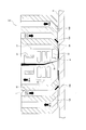
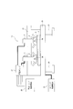
- FIG. 1 is a cross-sectional explanatory view of a focused ion beam device according to a first embodiment of the present invention.
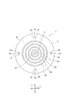
- FIG. 2 is a bottom view of a differential exhaust device provided in the focused ion beam device according to the first embodiment of the present invention.
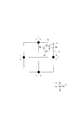
- FIG. 3 is a plan explanatory view showing the relationship between the head portion and the substrate support in the focused ion beam device according to the first embodiment of the present invention.
- FIG. 4 is a flowchart showing the control and operation of the focused ion beam device 1 according to the first embodiment of the present invention.
- FIG. 5 is a cross-sectional explanatory view of the focused ion beam device according to the first modification of the first embodiment of the present invention.
- FIG. 6 is a bottom view of the differential exhaust device provided in the focused ion beam device according to the second modification of the first embodiment of the present invention.
- FIG. 7 is a cross-sectional view taken along the line VII-VII of FIG. 8, which is a cross-sectional view of a main part of the focused ion beam device according to the third modification of the first embodiment of the present invention.
- FIG. 8 is a bottom view of the differential exhaust device provided in the focused ion beam device according to the third modification of the first embodiment of the present invention.
- FIG. 9 is a cross-sectional view of a main part of the focused ion beam device according to the first embodiment of the present invention.
- FIG. 10 is a bottom explanatory view showing a differential exhaust device provided in the focused ion beam device according to the fifth modification of the first embodiment of the present invention.
- FIG. 11 is an explanatory diagram schematically showing a focused ion beam device according to a second embodiment of the present invention.
- FIG. 12 is an explanatory diagram schematically showing a focused ion beam device according to a modification 1 of the second embodiment of the present invention.
- FIG. 13 is a cross-sectional view of a main part showing a focused ion beam device according to a third embodiment of the present invention.
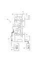
- FIG. 14 is a configuration explanatory view showing a focused ion beam device according to a fourth embodiment of the present invention.
- FIG. 11 is an explanatory diagram schematically showing a focused ion beam device according to a second embodiment of the present invention.
- FIG. 12 is an explanatory diagram schematically showing a focused ion beam device according to a modification 1 of the second embodiment of the present invention.
- FIG. 15 is a configuration explanatory view showing a focused ion beam device according to a fifth embodiment of the present invention.
- FIG. 16 is a configuration explanatory view showing a focused ion beam device according to a sixth embodiment of the present invention.
- FIG. 17 is a configuration explanatory view showing a focused ion beam device according to a seventh embodiment of the present invention.
- FIG. 18 is an explanatory diagram showing a conventional repair device including a focused ion beam optical system.
- FIG. 19 is an explanatory diagram showing a process of repairing a large photomask using a conventional repair device.
- the focused energy beam apparatus has an focused ion beam apparatus as a repair device and an electron beam drawing function having a direct drawing function on the substrate to be processed, depending on the type of the emitted energy beam and the processing application to the substrate to be processed. It can be applied to devices, scanning electron microscopes that enable observation of the surface state of the substrate to be processed, and the like. Further, the differential exhaust device according to the present invention is provided in the focused energy beam device.
- the focused energy beam device according to the embodiment of the present invention will be described by applying it to a focused ion beam device that emits an ion beam to a substrate to be processed.
- FIG. 1 shows a schematic configuration of a focused ion beam device 1 according to a first embodiment.
- the focused ion beam device 1 includes a differential exhaust device 2, a focused ion beam column (hereinafter, also referred to as a FIB column) 3 as a focused energy beam column, a substrate support 4, and four laser displacements as a gap measuring unit.
- a total of 5A, 5B, 5C, 5D (see FIG. 2), a displacement drive unit 6, and a gap control unit 7 are provided.
- the board support base 4 is designed to support the board 8 to be processed in a state of being placed on the board support base 4. In this embodiment, a large photomask is applied as the substrate 8 to be processed.
- the board support 4 is a stage that can be moved in the XY directions.
- the displacement drive unit 6 has a function of freely changing the inclination of the substrate support 4.
- an elevating drive means may be provided under a plurality of locations (for example, four corner portions) of the substrate support base 4. By adjusting the height of each part of the substrate support 4 by these elevating drive means, the substrate 8 to be processed can be changed to a desired inclined state.
- FIG. 2 is a bottom view of the differential exhaust device 2.
- the differential exhaust device 2 includes a head portion 9, a vacuum pump (not shown), and a discharge pump.
- the head portion 9 is composed of a disk-shaped metal plate having a very small area as compared with the area of the surface to be processed 8A of the substrate 8 to be processed.
- the head portion 9 can face an arbitrary region of the surface to be processed 8A by moving the substrate support 4 in the XY directions.
- annular grooves 10A, 10B, 10C, and 10D arranged concentrically (on concentric circles) are formed on the facing surface (lower surface) 9A of the head portion 9.
- the inner region of the innermost annular groove 10A among the plurality of annular grooves 10A, 10B, 10C, and 10D is treated with respect to the surface to be processed 8A of the substrate 8 to be processed (film formation treatment by ion beam irradiation).
- An opening 11 is provided to form a processing space Sp that enables the above.
- the FIB column 3, which will be described later, is connected to the opening 11 so as to communicate with the opening 11.
- the groove formed so as to surround the center of the head portion 9 is referred to as an "annular groove", but a circular loop-shaped groove, a square loop-shaped groove, or a part of the loop is missing.
- it is defined to include a C-shaped groove, a plurality of grooves intermittently arranged in a loop, and the like.
- At least one (three in the present embodiment) annular grooves 10B, 10C, 10D of the plurality of annular grooves 10A, 10B, 10C, 10D are connected to a vacuum pump (not shown) via a connecting pipe 12. ing.
- the innermost annular groove 10A is connected to a depot gas supply source (not shown) that supplies depot gas (deposit gas, CVD gas) via a connecting pipe 13.
- the head portion 9 has a function of increasing the degree of vacuum in the processing space Sp by the air suction action from the annular grooves 10B, 10C, 10D in a state where the facing surface 9A faces the surface to be processed 8A.
- the head portion 9 reliably supplies the deposition gas from the innermost annular groove 10A to the processing space Sp adjusted to a high degree of vacuum in this way, and the surface to be processed 8A facing the opening 11 It is possible to perform CVD film formation in the area of.
- the substantial gap Gg between the facing surface 9A of the head portion 9 and the surface to be processed 8A is set to about 30 ⁇ m.
- the internal vacuum state can be maintained without breaking the high vacuum state of the processing space Sp. If the head portion 9 is tilted with respect to the surface to be processed 8A and a part of the outer peripheral portion of the head portion 9 is separated from the surface to be processed 8A and the gap exceeds, for example, 40 ⁇ m, the differential exhaust function is performed at that location. It becomes impossible to maintain the local vacuum state due to.
- light transmission openings 14A, 14B, 14C, 14D are formed at four locations along the peripheral edge of the facing surface 9A in the outer region of the outermost annular groove 10D. There is. In these light transmitting openings 14A, 14B, 14C, 14D, transparent light transmitting plates 15A, 15B, 15C, 15D are embedded from the opening end side opposite to the facing surface 9A.
- the laser displacement meters 5A, 5B, 5C, and 5D perform distance measurement (displacement amount detection) by, for example, a combination of a light projecting element (not shown) and a linear image sensor (Linear Image Sensor). In general, it is known that the measurement accuracy of a laser displacement meter decreases when the displacement amount is 30 ⁇ m or less.
- the laser displacement meters 5A, 5B, 5C, and 5D are arranged on the respective light transmission plates 15A, 15B, 15C, and 15D, respectively. These laser displacement meters 5A, 5B, 5C, 5D are the distances between the lower surfaces of the light transmitting plates 15A, 15B, 15C, 15D and the surface to be processed 8A through the light transmitting openings 14A, 14B, 14C, 14D (hereinafter). It is set to detect Gm (called a management gap). That is, as shown in FIG.
- the offset gap Gos from the facing surface 9A to the light transmitting plate 15A (15B, 15C, 15D) is reduced from the control gap Gm, thereby reducing the actual gap Gg. Can be obtained. Since the control gap Gm may be a gap longer than 30 ⁇ m, detection can be performed in a region where the measurement accuracy of the laser displacement meter is good.
- FIB column (Focused ion beam column: FIB column)
- the FIB column 3 is arranged on the surface side (upper surface side) opposite to the facing surface 9A in the head portion 9, and is connected in a state of being fitted so that the tip portion is buried in the opening 11 of the head portion 9. ..
- the FIB column 3 includes a lens barrel 16 communicating with the processing space Sp, and a focused ion beam optical system 17 built in the lens barrel 16. From the tip of the FIB column 3, the ion beam Ib is emitted toward the surface to be processed 8A of the substrate 8 to be processed so as to pass through the opening 11. In this embodiment, the tip of the lens barrel 16 is formed so as to become thinner toward the tip.
- the focused ion beam optical system 17 includes an ion source 36 that generates an ion beam Ib, a condenser lens 37 that converges the generated ion beam Ib, a deflector 38 that scans the ion beam Ib, and an objective that converges the ion beam Ib. It is provided with an electrostatic lens 39.
- a gallium (Ga) ion source is mainly used, but a rare gas such as argon (Ar) may be inductively coupled plasma (ICP), gas electric field ionized, or a rare gas ion source may be used. Is also possible.
- ICP inductively coupled plasma
- gas electric field ionized or a rare gas ion source may be used. Is also possible.
- the lens of the ion beam Ib it is preferable to use an electric field lens.
- W (CO) 6 can be used as the CVD deposition gas.
- the focused ion beam is applied to W (CO) 6 in the vicinity of the substrate, it is decomposed into W and CO, and W is deposited on the substrate.
- an elevating means 18 for raising and lowering the FIB column 3 and the differential exhaust device 2 is provided.
- the upper part of the elevating means 18 is supported by the support frame 20 by the support portion 19.
- the elevating means 18 has a function of moving the FIB column 3 and the differential exhaust device 2 up and down to separate the focused ion beam device 1 from the substrate 8 to be processed.
- the elevating means 18 is provided on the upper part of the FIB column 3, but the support frame 20 may have an elevating function.
- the gap control unit 7 is a head unit 9 corresponding to each laser displacement meter 5A, 5B, 5C, 5D based on the detection value (distance information) of the management gap Gm detected by the laser displacement meters 5A, 5B, 5C, 5D.
- the displacement drive unit 6 is driven so that the facing surface 9A and the surface to be processed 8A are parallel to each other so that the substantial gap Gg between the facing surface 9A and the surface to be processed 8A at each location is parallel to each other at a predetermined uniform distance. It is designed to output a signal.
- the displacement drive unit 6 is provided with four displacement drive units (indicated by E, F, G, H) under the substrate support 4.
- the four displacement drive units E, F, G, and H are arranged in a square shape as shown by black circles. Let the diagonal distance of this square be 2L.
- the directions of the rectangular sides of the board support 4 are the X direction and the Y direction.
- the laser displacement meters 5A, 5B, 5C, and 5D are arranged as shown in FIG. That is, four laser displacement meters 5A, 5B, 5C, and 5D are arranged on concentric circles having a radius r of the circular head 9.
- the coordinates of the center of the head portion 9 are (hx, hy), and the radius of the head portion 9 is r.
- the substrate 8 to be processed is set on the substrate support 4, and the planned portion to be processed is moved so as to be located below the head portion 9.
- the gap control unit 7 drives the elevating means 18 to move the facing surface 9A of the head unit 9 to a predetermined height position above the surface to be processed 8A.
- step S1 The target value h of the gap between the facing surface 9A of the head portion 9 and the surface to be processed 8A is set (step S1).
- step S2 The gap with the surface to be processed 8A is measured with a laser displacement meter 5A, 5B, 5C, 5D (step S2). Let the measured values of each displacement be hA, hB, hC, hD.
- the gap with the surface to be processed 8A is measured again with the laser displacement meters 5A, 5B, 5C, 5D (step S7). Let the measured values of each gap be hA, hB, hC, and hD.
- step S9 If the difference at any one of the above differences (measurement position) is large, that is, if there is also one point that greatly deviates from the average value hav, the process returns to step S3 (step S9).
- step S9 if the deviation from the average value hav at any point is small, the displacement drive units E, F, G, and H are displaced by h—hav, and the control ends (step S10).
- the gap control unit 7 controls the displacement drive units E, F, G, and H based on the detection information from the laser displacement meters 5A, 5B, 5C, and 5D.
- such control is performed when the substrate 8 to be processed is moved so that the portion to be processed faces the facing surface 9A of the head portion 9.
- the head portion 9 Can hold the substantial gap Gg in a desired gap while keeping it parallel to the surface to be processed 8A.
- the line connecting the laser displacement meter 5A and the laser displacement meter 5C, the laser displacement meter 5B, and the laser displacement meter 5D The lines connecting with are arranged so as to be orthogonal to each other. That is, the group of the four laser displacement meters 5A, 5B, 5C, and 5D has a pair arranged on both sides in the X direction centered on the center of the opening 11 and a pair arranged on both sides in the X direction centered on the center of the opening 11 in the Y direction. It is composed of two pairs, one pair arranged on both sides.
- this focused ion beam device 1 it is possible to perform processing even on the edge of the substrate 8 to be processed. That is, this focused ion beam device 1 has an effect that a wide range of the substrate 8 to be processed can be effectively processed.
- the laser displacement meters 5A, 5B, 5C, 5D are arranged in a direction away from the surface to be processed 8A from the facing surface 9A, and the distance from the surface to be processed 8A is the laser.
- the displacement meters 5A, 5B, 5C, and 5D are offset so as to be in the high-precision measurement area. Therefore, it is possible to accurately obtain the substantial gap Gg between the surface to be processed 8A and the facing surface 9A at the four locations where the laser displacement meters 5A, 5B, 5C, and 5D are provided.
- the innermost annular groove 10A of the facing surface 9A of the head portion 9 of the differential exhaust device 2 is further formed by the ion beam Ib. Can be approached to. Therefore, the depot gas can be reliably guided to the processing space Sp, and a stable CVD film formation can be reliably produced. Further, by making the tip of the lens barrel 16 thinner, it becomes possible to bring a plurality of annular grooves 10A, 10B, 10C, 10D closer to the vicinity of the small opening 11, and the differential exhaust device 2 can be made compact. Can be done.
- the focused ion beam device 1A shown in FIG. 5 is a modification 1 of the focused ion beam device 1 according to the first embodiment described above.
- This focused ion beam device 1A includes four displacement drive units 6A on the FIB column 3.
- the four displacement drive units 6A are incorporated in a column suspension device provided on the upper part of the FIB column 3.
- An elevating means 18 similar to that of the first embodiment is provided on the upper portion of the displacement drive unit 6A.
- the four displacement drive units 6A are arranged directly above the laser displacement meters 5A, 5B, 5C, and 5D.
- the displacement drive unit 6A is a means for varying the tilted state of the FIB column 3 and the differential exhaust device 2.
- the displacement drive unit 6 is not provided on the substrate support 4 side as in the first embodiment, and the FIB is parallel to the facing surface 9A and the surface to be processed 8A on the differential exhaust device 2 side. It is configured to be adjusted by four displacement drive units 6A provided on the column 3 side.
- a target value h of a gap between the facing surface 9A of the head portion 9 and the surface to be processed 8A is set.
- the gap with the surface to be processed 8A is measured with the laser displacement meters 5A, 5B, 5C, 5D. Let the measured values of each gap be hA, hB, hC, and hD.
- the displacement drive unit 6A is provided directly above the four laser displacement meters 5A, 5B, 5C, and 5D, respectively, but the displacement drive unit 6A is provided directly above the three laser displacement meters. It may be configured.
- the following control may be performed.
- the target value h of the gap is set.
- the gap with the surface to be processed 8A is measured with three laser displacement meters 5A, 5B, and 5C. Let the measured values of each displacement be hA, hB, hC. Each displacement drive unit is displaced by h-hA, h-hB, and h-hC, respectively.
- the laser displacement meters 5A, 5B, and 5C are used to measure and confirm the gap with the surface to be processed 8A.
- FIG. 6 is a bottom view of the differential exhaust device 2A according to the second modification of the first embodiment of the present invention.
- the differential exhaust device 2A includes three light transmission openings 14E, 14F, 14G at equal intervals along the outer periphery of the head portion 9, and a laser corresponding to these light transmission openings 14E, 14F, 14G. It is equipped with displacement meters 5E, 5F, 5G.
- the facing surface 9A and the surface to be processed 8A are parallel to each other by measuring the control gap Gm at three points of the laser displacement meters 5E, 5F, and 5G. Displacement drive control for output is possible.
- the head unit 9 may be configured to include a laser displacement meter as a gap measuring unit at three or more locations.
- FIG. 7 and 8 show the focused ion beam device 1B according to the third modification of the first embodiment.
- FIG. 7 is a cross-sectional view taken along the line VII-VII of FIG.
- FIG. 8 is a bottom view of the differential exhaust device 2B according to the modified example 3.
- the laser displacement meter is not arranged at an offset rearward, but is provided on the outer peripheral portion of the head portion 9 and is provided on the outer peripheral portion of the head portion 9.
- the position of the tip portion of the head portion 9 is set to the same level as the facing surface 9A of the head portion 9.
- the laser displacement meters 5H, 5I, 5J, and 5K are used, but of course, another gap sensor may be used as the gap measuring unit.
- nitrogen gas (N2) as an inert gas is blown from the outermost annular groove 10D in the head portion 9 onto the surface to be treated 8A to generate a gas curtain.
- N2 nitrogen gas
- the inside of the lens barrel 16 can be purged with the inert gas, which improves the environment.
- the blowing of the inert gas has the effect of urging the head portion 9 in a direction away from the surface to be processed 8A to raise the head portion 9. Therefore, in this modification 3, there is an effect of canceling the vacuum pressure due to the differential exhaust.
- FIG. 9 shows the focused ion beam device 1C according to the modified example 4 of the first embodiment.
- the dry nitrogen gas (N2) is set to be ejected diagonally outward in the outermost annular groove 10D of the head portion 9.
- the annular groove 10D is formed so as to be inclined outward.
- the delivery pressure is set so that the nitrogen gas (N2) is injected from the annular groove 10D at a high speed.
- the nitrogen gas (N2) injected from the annular groove 10D is exhausted into the atmosphere at high speed, so that the gas on the processing space Sp side can be exhausted together with the high-speed flow of nitrogen gas.
- the processing space Sp can be further increased in vacuum. can.
- this modification 4 by injecting a dry nitrogen gas, it is possible to reduce the mixing of water into the processing space Sp. Further, since the nitrogen gas (N2) as an inert gas is sprayed on the surface 8A to be treated to generate a gas curtain, the inside of the lens barrel 16 can be purged with the inert gas, which improves the environment. Further, the blowing of the inert gas has the effect of urging the head portion 9 in a direction away from the surface to be processed 8A to raise the head portion 9. Therefore, even in this modification 4, there is an effect of canceling the vacuum pressure due to the differential exhaust.
- FIG. 10 shows a differential exhaust device 2C of a focused ion beam device according to a modification 5 of the first embodiment.
- the portion shown by the alternate long and short dash line in FIG. 10 is the substrate 8 to be processed.
- the planar shape of the head portion 9 is square, and laser displacement meters 5L, 5M, 5N, and 5O are provided on the sides of the center of each of the four sides thereof.
- FIG. 11 is an explanatory diagram schematically showing the focused ion beam device 1E according to the second embodiment of the present invention.
- a laser displacement meter or the like is not shown in FIG. 11, a laser displacement meter or the like as a gap measuring unit is provided as in the focused ion beam device 1 according to the first embodiment.
- the annular groove is simplified into two annular grooves 10A and 10D, which are an exhaust system and an intake system.
- the objective electrostatic lens 17A of the focused ion beam optical system 17 and the microchannel plate 21 are provided in the tip end portion of the lens barrel 16.
- the microchannel plate 21 is arranged on the downstream side of the beam (position close to the tip of the lens barrel 16) with respect to the objective electrostatic lens 17A.
- the microchannel plate 21 has an ion beam passage port 21A opened in the center, and the peripheral portion thereof is a detection unit 21B capable of capturing secondary charged particles P generated from the substrate 8 to be processed. It is supposed to be.
- the ion beam Ib is irradiated with the supply of the depot gas stopped. Then, the secondary charged particles P generated from the surface to be processed 8A to which the ion beam Ib is incident are incident, so that electrons are generated in the detection unit 21B. In this way, the generated electrons can be amplified by the avalanche current to obtain information on the surface of the surface to be processed 8A. Therefore, according to the focused energy beam device 1E of the present embodiment, the state of the surface to be processed 8A can be detected with high sensitivity.
- the working distance (WD) of the objective electrostatic lens 17A can be brought closer, and the focused ion beam optical system can be separated from the focused ion beam optical system in the vacuum chamber as in the conventional case.
- the capture efficiency of the secondary charged particles P can be improved as compared with the method of arranging the scintillator at the above position for detection.
- the working distance of the objective electrostatic lens 17A is shortened in this way, it becomes difficult to separately arrange a structure such as a depot gas nozzle near the tip of the lens barrel 16.
- the annular groove 10A for supplying the depot gas is also provided at the tip of the lens barrel 16. Therefore, the ion beam Ib can be irradiated while filling the processing space Sp with the depot gas. Therefore, the problem that the supply of depot gas becomes difficult due to the shortened working distance does not occur.
- the working distance of the objective electrostatic lens 17A can be shortened, so that the focusing efficiency of the focused ion beam optical system 17 can be improved and it is possible to irradiate a fine ion beam Ib. It becomes.
- the position of the substrate 8 to be processed for observing the state of the surface to be processed 8A by the ion beam Ib is the same as the position of the substrate 8 to be processed when the CVD film formation is performed. There is no need to move the processing board 8. Therefore, it is possible to avoid the problem that the processing position shifts as the substrate 8 to be processed moves.
- the surface state of the substrate 8 to be processed can be observed.
- a scintillator can also be used as the detector 22.
- Other configurations of the focused ion beam device 1F are substantially the same as the configurations of the first and second embodiments.
- FIG. 13 shows a focused ion beam device 1G according to a third embodiment of the present invention.
- a levitation pad 24 circulates around the outer peripheral edge of the facing surface 9A of the head portion 9 of the differential exhaust device 2D and is integrated with the facing surface 9A. It is provided in.
- the floating pad 24 is connected to a discharge pump that supplies nitrogen gas (N2) as an inert gas via a connecting pipe 4025.
- the levitation pad 24 has a flat annular pipe shape, and a plurality of slit-shaped or circular openings are formed on the lower surface thereof, and the inert gas is discharged from the openings.
- laser displacement meters 5A, 5B, 5C, and 5D are arranged at four locations on the outer peripheral portion of the levitation pad 24.
- Other configurations of the focused ion beam device 1G according to the present embodiment are substantially the same as those of the focused ion beam device 1 according to the first embodiment described above.
- the levitation pad 24 forms a gas curtain by blowing an inert gas toward the surface to be treated 8A. Therefore, the levitation pad 24 urges the head portion 9 in a direction away from the surface to be processed 8A.
- the inside of the lens barrel 16 can be purged with the inert gas, which improves the environment.
- the blowing of the inert gas has the effect of urging the head portion 9 in a direction away from the surface to be processed 8A to raise the head portion 9. Therefore, in the present embodiment, there is an effect of canceling the vacuum pressure due to the differential exhaust.
- FIG. 14 shows a focused ion beam device 1H according to a fourth embodiment of the present invention.
- the focused ion beam device 1H includes an XY precision stage 25.
- the XY precision stage 25 is provided with tilt adjusting support legs 26 as displacement driving portions that expand and contract up and down at each of the lower portions of the four corners. These inclination adjusting support legs 26 are connected to a gap control unit (not shown).
- a substrate support 4 that moves in the XY directions is provided on the XY precision stage 25.
- a substrate 8 to be processed such as a photomask is placed on the substrate support 4.
- a support frame 20 is erected on the XY precision stage 25.
- the FIB column 3 is suspended in the center of the support frame 20.
- a differential exhaust device 2 is integrally provided at the lower end of the FIB column 3.
- the configuration of the FIB column 3 and the differential exhaust device 2 is substantially the same as the configuration of the focused ion beam device 1 according to the first embodiment described above.
- a vacuum pump 27 is connected to the FIB column 3, and a vacuum pump control power supply 28 is connected to the vacuum pump 27. Further, a stage control power supply 29 is connected to the XY precision stage 25.
- the optical alignment microscope 30 is provided at an upper position corresponding to the alignment mark 8B formed at the four corners of the substrate 8 to be processed, which is arranged at a predetermined position on the XY precision stage 25. ing.
- the substrate to be processed and the focused ion beam optical system are housed in a large vacuum chamber. Then, the secondary electrons and secondary ions emitted from the substrate to be treated irradiated with the ion beam are detected by a charge particle detector installed outside the FIB column, and the change in the intensity thereof is observed to be the substrate to be treated. I was observing the surface shape of the. Similarly, in a vacuum, secondary charged particles from the alignment mark were acquired by irradiation with an ion beam for alignment. Therefore, it was necessary to move the alignment marks at the four corners of the substrate to be processed set in the vacuum chamber to the irradiation position of the FIB column. Such movement required the XY precision stage to cover an area about four times that of the substrate to be processed, further enlarging the vacuum chamber.
- the local vacuum space is realized by using the differential exhaust device 2, so that the atmospheric pressure is outside the area being processed, so that the optical alignment is performed.
- the microscope can be easily installed. As shown in FIG. 11, in the present embodiment, alignment is performed using the alignment marks 8B at the four corners of the substrate 8 to be processed, and the relative relationship between the position of the optical alignment microscope 30 and the processing position by the FIB column 3 The coordinates can be fixed. Therefore, according to the focused ion beam device 1H of the present embodiment, a stroke for alignment by the XY precision stage 25 becomes unnecessary. In addition, according to the focused ion beam device 1H, the travel time for alignment can be shortened.
- FIG. 15 shows a focused ion beam device 1I according to a fifth embodiment of the present invention.
- the focused ion beam device 1I of the present embodiment has substantially the same configuration as the focused ion beam device 1H of the fourth embodiment.
- the configuration different from the fourth embodiment is that the optical microscope 31 is installed on the FIB column 3 with an offset distance set. Although the optical alignment microscope 30 is not provided in the present embodiment, it may be added.
- the substrate to be processed and the focused ion beam optical system are housed in a large vacuum chamber. Then, secondary electrons and secondary ions emitted from the substrate to be treated irradiated with an ion beam in a vacuum are detected by a charge particle detector installed outside the FIB column, and the change in intensity is observed.
- the surface shape of the substrate to be treated was observed as an ion image. Generally, the irradiation position is confirmed using this ion image, but since the secondary charged particles depend on the surface shape (tilt angle) of the substrate to be processed, only the surface shape is used as an ion image. Detected. Therefore, when the surface shape has few undulations, the ion image has low contrast, which makes it difficult to confirm the irradiation position and may reduce the position accuracy.
- the degree of vacuum can be set to a high level locally by the differential exhaust device 2, so that the entire substrate 8 to be processed needs to be placed in a vacuum.
- the optical microscope 31 can be installed in the vicinity of the FIB column 3. Therefore, not only the surface undulation information but also information such as color can be obtained by directly using a high-resolution optical microscope 31 or a laser microscope (not shown) for the surface portion of the substrate 8 to be treated by the ion beam. Therefore, in the present embodiment, the position to be processed by the ion beam can be easily confirmed.
- the ion beam irradiation position is immediately offset while confirming the position in the optical image of the position to be processed.
- the substrate 8 to be processed can be set in. As described above, in the present embodiment, the irradiation position can be specified even on the surface of the substrate 8 to be treated with less undulations, and ion beam irradiation can be performed with high accuracy.
- FIG. 16 shows a focused ion beam device 1J according to a sixth embodiment of the present invention.
- the focused ion beam device 1J supports the XY precision stage 25, the tilt adjusting support legs 26 provided at the lower portions of the four corners of the XY precision stage 25, and the substrate support base 4.
- a frame 20, four FIB columns 3 suspended from the support frame 20, and a differential exhaust device 2 provided at the lower end of the FIB column 3 are provided.
- a vacuum pump 27 is connected to each FIB column 3, and a vacuum pump control power supply 28 is connected to the vacuum pump 27. Further, a stage control power supply 29 is connected to the XY precision stage 25.
- the four FIB columns 3 are arranged so as to correspond to the region in which the substrate 8 to be processed is divided into four.
- a stroke four times the area of the substrate is required for the substrate support 4.
- the XY precision stage 25 can be operated to reduce the movable stroke of the board support base 4, and the footprint of the apparatus can be reduced. Can be kept small.
- the substrate can be processed at high speed.
- FIG. 17 shows a focused ion beam device 1K according to a seventh embodiment of the present invention.
- the focused ion beam device 1K includes a substrate stage 32.
- the board stage 32 is provided with tilt adjusting support legs 26 that expand and contract up and down at each of the lower portions of the four corners. These inclination adjusting support legs 26 are connected to a gap control unit (not shown).
- a board support base 4 is provided on the board stage 32.
- a substrate 8 to be processed such as a photomask is placed on the substrate support 4.
- an XY gantry stage 33 is erected on the substrate stage 32.
- the XY gantry stage 33 is provided with a movable block 34 so as to be movable in the XY directions.
- the FIB column 3 and the optical alignment microscope 30 are fixed to the movable block 34.
- a differential exhaust device 2 is integrally provided at the lower end of the FIB column 3.
- the configuration of the FIB column 3 and the differential exhaust device 2 is substantially the same as the configuration of the focused ion beam device 1 according to the first embodiment described above.
- a vacuum pump 27 is connected to the FIB column 3. Further, the stage control power supply 35 is connected to the movable block 34.
- the movable block 34 is provided on the XY gantry stage 33 so as to be movable in the XY directions, so that the movable block 34 is provided with the position of the substrate 8 to be processed fixed.
- the FIB column 3 and the optical alignment microscope 30 can be moved. Since the position of the substrate 8 to be processed can be fixed in this way, the footprint of the apparatus can be reduced.
- a differential exhaust device capable of reliably maintaining a differential exhaust function even on a large-sized substrate to be processed having warpage or swell, and good processing can be performed.
- a focused ion beam device can be realized.
- the quality of the processing work in this processing space can be improved.
- the device since the device can be made compact, the equipment cost and the management cost can be reduced.
- the gap between the outer peripheral edge of the head portion 9 and the surface to be processed 8A can be made uniform so that the facing surface 9A of the head portion 9 and the surface to be processed 8A of the substrate 8 to be processed are kept in parallel. It is possible to prevent the high vacuum from breaking at the outer peripheral edge. Therefore, good processing (observation, film formation, etc.) can be performed in the processing space Sp.
- the focused energy beam apparatus has been described by applying it to a focused ion beam apparatus as a repair apparatus, but in addition to this, an electron beam drawing apparatus having a direct drawing function on a substrate to be processed, It can be applied to a scanning electron microscope or the like that enables observation of the surface state of the substrate to be processed.
- the number of annular grooves formed in the differential exhaust device is not limited to four, and at least two or more for exhausting and blowing out may be provided.
- the displacement drive units 6 and 6A and the tilt adjusting support legs 26 are used as the displacement drive units, but the present invention is not limited to these, and other means capable of adjusting the inclination and the gap. Of course, may be applied.
- the laser displacement meters 5A, 5B, 5C, and 5D are used as the gap measuring unit, but a pressure gauge may be used instead of these.
- the displacement drive unit can be controlled by estimating the inclination and distance between the surface to be processed 8A and the facing surface 9A of the head unit 9 based on the pressure measurement values of these pressure gauges.
- the laser displacement meters 5A, 5B, 5C, and 5D are applied as the gap measuring unit, but in addition to these, contact type sensors, ultrasonic sensors, capacitance type sensors, and the like can also be applied. .. Considering the measurement accuracy on the order of ⁇ m obtained by the differential exhaust as in the above embodiment, the above laser displacement meters 5A, 5B, 5C, 5D are preferable. Further, in the above embodiment, the configuration is provided with four laser displacement meters 5A, 5B, 5C, and 5D, but the present invention includes at least three or more gap measuring portions along the peripheral edge of the head portion 9. It may be configured.
- the FIB column 3 that emits an ion beam Ib as an energy beam has been described, but a repair that has a local vacuum space and irradiates a laser beam to remove or form wiring. It is also possible to apply the differential exhaust device of the present invention to a device or the like.
Landscapes
- Chemical & Material Sciences (AREA)
- Analytical Chemistry (AREA)
- Physics & Mathematics (AREA)
- General Physics & Mathematics (AREA)
- Engineering & Computer Science (AREA)
- Plasma & Fusion (AREA)
- Drying Of Semiconductors (AREA)
- Electron Beam Exposure (AREA)
- Health & Medical Sciences (AREA)
- Toxicology (AREA)
- Laser Beam Processing (AREA)
- Container, Conveyance, Adherence, Positioning, Of Wafer (AREA)
Abstract
Description
該レーザ変位計は、前記対向面よりも前記被処理面から離れる方向にオフセット配置され、前記被処理面との距離が前記レーザ変位計の高精度測定領域となるように設定されていることが好ましい。
図1は、第1の実施の形態に係る集束イオンビーム装置1の概略構成を示している。集束イオンビーム装置1は、差動排気装置2と、集束エネルギービームカラムとしての集束イオンビームカラム(以下、FIBカラムともいう)3と、基板支持台4と、ギャップ測定部としての4つのレーザ変位計5A,5B,5C,5D(図2参照)と、変位駆動部6と、ギャップ制御部7と、を備える。
以下に、図1および図2を用いて差動排気装置2の構成を説明する。なお、図2は、差動排気装置2の下面図である。差動排気装置2は、ヘッド部9と、図示しない真空ポンプと、吐出ポンプと、を備える。
レーザ変位計5A,5B,5C,5Dは、例えばともに図示しない投光素子とリニアイメージセンサ(Linear Image Sensor)との組み合わせで、測距(変位量の検出)を行う。一般に、レーザ変位計において、変位量が30μm以下の場合に測定精度が低下することが知られている。
FIBカラム3は、ヘッド部9における対向面9Aと反対側の面側(上面側)に配置され、ヘッド部9の開口部11に先端部が埋没するように嵌め込まれた状態で連結されている。
ギャップ制御部7は、レーザ変位計5A,5B,5C,5Dが検出した管理ギャップGmの検出値(距離情報)に基づき、それぞれのレーザ変位計5A,5B,5C,5Dが対応するヘッド部9の各箇所における対向面9Aと被処理面8Aとの実質ギャップGgが所定の均等な距離を隔てて、対向面9Aと被処理面8Aとが平行となるように、変位駆動部6に駆動制御信号を出力するようになっている。
以下、本実施の形態に係る集束イオンビーム装置1において、ヘッド部9の対向面9Aに対して被処理基板8の被処理面8Aを所定のギャップを保って平行に対向配置させる動作について説明する。図3に示すように、本実施の形態では、変位駆動部6は基板支持台4の下に4つの変位駆動部(E,F,G,Hで示す)設けられている。4つの変位駆動部E,F,G,Hは、黒丸で示すように正方形状に配置する。この正方形の対角線距離を2Lとする。基板支持台4の長方形の辺の向きをX方向、Y方向とする。そして、レーザ変位計5A,5B,5C,5Dを図2に示すような配置にする。すなわち、円形のヘッド9の半径rの同心円の上に、4点のレーザ変位計5A,5B,5C,5Dが配置されている。ここで、ヘッド部9の中心の座標を(hx、hy)とし、ヘッド部9の半径をrとする。
(1)ヘッド部9の対向面9Aと、被処理面8Aと、のギャップの目標値hを設定する(ステップS1)。
mx=(hD-hB)/2r
ΔhF=-(L+hx)mx
ΔhH=(L-hx)mx
my=(hA-hC)/2r
ΔhA=(L-hy)my
ΔhC=-(L+hy)my
本発明の第1の実施の形態に係る集束イオンビーム装置1によれば、フォトマスクなどの被処理基板8が大型化して、被処理基板8にうねりや反りが発生した場合でも、ヘッド部9が被処理面8Aと平行を保ちながら実質ギャップGgを所望のギャップに保持することが可能となる。
図5に示す集束イオンビーム装置1Aは、上記した第1の実施の形態に係る集束イオンビーム装置1の変形例1である。この集束イオンビーム装置1Aは、FIBカラム3の上に4つの変位駆動部6Aを備える。4つの変位駆動部6Aは、FIBカラム3の上部に設けたカラム吊り下げ装置の中に組み込まれている。変位駆動部6Aの上部には、第1の実施の形態と同様の昇降手段18が設けられている。4つの変位駆動部6Aは、レーザ変位計5A,5B,5C,5Dの直上に配置されている。
それぞれの変位の測定値をhA,hB,hC,hDとする。
mx=(hD-hB)/2r
ΔhF=-(L+hx)mx
ΔhH=(L-hx)mx
my=(hA-hC)/2r
ΔhA=(L-hy)my
ΔhC=-(L+hy)my
図6は、本発明の第1の実施の形態の変形例2に係る差動排気装置2Aの下面図である。この差動排気装置2Aは、ヘッド部9の外周に沿って等間隔に3つの光透過用開口部14E,14F,14Gを備え、これら光透過用開口部14E,14F,14Gに対応してレーザ変位計5E,5F,5Gを備える。
図7および図8は、第1の実施の形態の変形例3に係る集束イオンビーム装置1Bを示している。図7は、図8のVII-VII断面図である。図8は、変形例3に係る差動排気装置2Bの下面図である。この変形例3では、上記第1の実施の形態に係る集束イオンビーム装置1のように、レーザ変位計を後方にオフセットして配置せずに、ヘッド部9の外周部に設け、レーザ変位計の先端部の位置をヘッド部9の対向面9Aと同レベルに設定している。この変形例3では、レーザ変位計5H,5I,5J,5Kを用いたが、他のギャップセンサをギャップ測定部として用いても勿論よい。
図9は、第1の実施の形態の変形例4に係る集束イオンビーム装置1Cを示している。
図10は、第1の実施の形態の変形例5に係る集束イオンビーム装置の差動排気装置2Cを示す。図10の一点鎖線示す部分は、被処理基板8である。この変形例5では、ヘッド部9の平面形状が正方形であり、その4辺のそれぞれの中央の側方にレーザ変位計5L,5M,5N,5Oが設けられている。
図11は、本発明の第2の実施の形態に係る集束イオンビーム装置1Eを模式的に示す説明図である。図11おいては、レーザ変位計などを図示しないが、上記第1の実施の形態に係る集束イオンビーム装置1と同様にギャップ測定部としてのレーザ変位計などを備える。また、図11においては、環状溝を排気系と吸気系の2つ環状溝10A,10Dに簡略化している。
を短くできるので、集束イオンビーム光学系17の集束効率も向上し、微細なイオンビームIbを照射することも可能となる。また、本実施の形態では、イオンビームIbによる被処理面8Aの状態の観察を行う被処理基板8の位置と、CVD成膜を行うときの被処理基板8の位置は同じであるため、被処理基板8を移動させる必要がない。このため、被処理基板8の移動に伴って処理位置がずれるという問題を回避できる。
図12に示すように、第2の実施の形態の変形例1に係る集束イオンビーム装置1Fでは、マイクロチャネルプレート21を用いずに、対物静電レンズ17Aのビーム下流側においてイオンビームIbの側方に検出器22を配置している。また、対物静電レンズ17Aのビーム上流側には、偏向器23を配置している。この集束イオンビーム装置1Fでは、被処理基板8の被処理面8Aを観察するときには、イオンビームIbを偏向器23で検出器22に近づく方向へ偏向させて、被処理基板8に対して斜めに入射させる。そして、被処理基板8にイオンビームIbが入射して発生した2次荷電粒子Pを検出器22で捕捉することにより、被処理基板8の表面状態の観察が可能となる。検出器22としては、シンチレータを用いることもできる。集束イオンビーム装置1Fの他の構成は、上記第1および第2の実施の形態の構成と略同様である。
図13は、本発明の第3の実施の形態に係る集束イオンビーム装置1Gを示している。
図13に示すように、この集束イオンビーム装置1Gは、差動排気装置2Dのヘッド部9の対向面9Aの外側に、この対向面9Aの外周縁に沿って浮上パッド24が周回して一体に設けられている。この浮上パッド24は、不活性ガスとしての窒素ガス(N2)を供給する吐出ポンプに連結パイプ4025を介して接続されている。この浮上パッド24は、扁平な環状のパイプ形状であり、下面に複数のスリット状または円形状の開口が形成され、この開口から不活性ガスを吐出するようになっている。また、浮上パッド24の外周部の4箇所には、レーザ変位計5A,5B,5C,5Dが配置されている。本実施の形態に係る集束イオンビーム装置1Gの他の構成は、上記した第1の実施の形態に係る集束イオンビーム装置1と略同様である。
図14は、本発明の第4実施の形態に係る集束イオンビーム装置1Hを示している。集束イオンビーム装置1Hは、X-Y精密ステージ25を備える。X-Y精密ステージ25は、四隅の下部のそれぞれに、上下に伸縮する変位駆動部としての傾斜調整用支持脚26が設けられている。これら傾斜調整用支持脚26は、図示しないギャップ制御部に接続されている。
図15は、本発明の第5の実施の形態に係る集束イオンビーム装置1Iを示している。
本実施の形態の集束イオンビーム装置1Iは、上記第4の実施の形態の集束イオンビーム装置1Hと、略同様の構成を有する。上記第4の実施の形態と異なる構成は、FIBカラム3にオフセット距離を設定して光学顕微鏡31を設置した構成である。なお、本実施の形態では、光学アライメント顕微鏡30を備えていないが、付加しても勿論よい。
図16は、本発明の第6実施の形態に係る集束イオンビーム装置1Jを示している。集束イオンビーム装置1Jは、X-Y精密ステージ25と、X-Y精密ステージ25の四隅の下部のそれぞれに設けられた上下に伸縮する傾斜調整用支持脚26と、基板支持台4と、支持フレーム20と、この支持フレーム20に吊り下げられた4つのFIBカラム3と、FIBカラム3の下端に設けられた差動排気装置2と、備える。
図17は、本発明の第7の実施の形態に係る集束イオンビーム装置1Kを示している。
集束イオンビーム装置1Kは、基板ステージ32を備える。基板ステージ32は、四隅の下部のそれぞれに、上下に伸縮する傾斜調整用支持脚26が設けられている。これら傾斜調整用支持脚26は、図示しないギャップ制御部に接続されている。
このように被処理基板8の位置は固定できるため、装置のフットプリントを小さくできる。
以上、本発明の実施の形態について説明したが、この実施の形態の開示の一部をなす論述および図面はこの発明を限定するものであると理解すべきではない。この開示から当業者には様々な代替実施の形態、実施例および運用技術が明らかとなろう。
Gm 管理ギャップ
Gos オフセットギャップ
Ib イオンビーム
P 2次荷電粒子
Sp 処理用空間
1A,1E,1F,1G,1H,1I,1J,1K 集束イオンビーム装置(集束エネルギービーム装置)
2,2A,2B,2C,2D 差動排気装置
3 集束イオンビームカラム(FIBカラム,集束エネルギービームカラム)
4 基板支持台
5A,5B,5C,5D レーザ変位計(ギャップ測定部)
6,6A 変位駆動部
7 ギャップ制御部
8 被処理基板
8A 被処理面
8B アライメントマーク
9 ヘッド部
9A 対向面
10A 環状溝(最も内側の環状溝)
10B,10C 環状溝
10D 環状溝(最も外側の環状溝)
11 開口部
12,13 連結パイプ
14A,14B,14C,14D 光透過用開口部
15A,15B,15C,15D 光透過板
16 鏡筒
17 集束イオンビーム光学系
17A 対物静電レンズ
18 昇降手段
19 支持部
20 支持フレーム
21 マイクロチャネルプレート
21A イオンビーム通過口
21B 検出部
22 検出器
23 偏向器
24 浮上パッド
25 X-Y精密ステージ
26 傾斜調整用支持脚(変位駆動部)
27 真空ポンプ
28 真空ポンプ制御電源
29 ステージ制御電源
30 光学アライメント顕微鏡
31 光学顕微鏡
32 基板ステージ
33 X-Yガントリステージ
34 可動ブロック
35 ステージ制御電源
40 連結パイプ
Claims (19)
- 被処理基板の被処理面に対して、該被処理面の任意領域に対向するように相対移動可能なヘッド部を備え、
前記ヘッド部における、前記被処理面と対向する対向面に、前記ヘッド部の中心を囲むように複数の環状溝が形成され、
前記ヘッド部における、前記複数の環状溝のうち最も内側の前記環状溝の内側領域に、前記被処理面に対する処理を可能にする処理用空間を形成する開口部が設けられ、
前記複数の環状溝のうち少なくとも1つ以上の前記環状溝に真空ポンプが連結され、
前記被処理面に前記対向面を対向させた状態で、前記環状溝からの吸気作用により、前記処理用空間を高真空度にする、差動排気装置であって、
前記ヘッド部または前記被処理基板を変位させて、前記被処理面と前記対向面との平行度および距離の調整が可能な変位駆動部と、
前記ヘッド部の前記対向面の周縁に沿って少なくとも3箇所以上にそれぞれ配置された、前記対向面と前記被処理面と間の距離を検出可能なギャップ測定部と、
前記ギャップ測定部が検出した、前記対向面と前記被処理面との距離情報に基づき、前記対向面と前記被処理面とが所定の距離を隔てて平行となるように前記変位駆動部を制御するギャップ制御部と、
を備える差動排気装置。 - 前記ギャップ測定部は、前記被処理面との間の空間の圧力を検出し、
前記ギャップ制御部は前記圧力の情報に基づいて前記変位駆動部を制御する、
請求項1に記載の差動排気装置。 - 前記被処理基板はX-Y方向に縦横の辺を有する長方形であり、
前記ヘッド部は、前記被処理基板のX-Y方向に沿って相対移動可能であり、
前記ギャップ測定部は、前記ヘッド部における最も外側に形成された前記環状溝の外側の4箇所に備えられ、
当該4箇所の前記ギャップ測定部の群は、前記対向面における前記開口部の中央を中心としてX方向の両側方に配置された対と、前記開口部の中央を中心としてY方向の両側方に配置された対と、の2対で構成される、
請求項1または請求項2に記載の差動排気装置。 - 前記ギャップ測定部は、レーザ変位計で構成され、
該レーザ変位計は、前記対向面よりも前記被処理面から離れる方向にオフセット配置され、前記被処理面との距離が前記レーザ変位計の高精度測定領域となるように設定されている、
請求項1または請求項3に記載の差動排気装置。 - 前記被処理基板に形成されたアライメントマークを検出する光学顕微鏡を備える、
請求項1から請求項4のいずれか一項に記載の差動排気装置。 - 前記ヘッド部の近傍にオフセット距離を隔てて、前記被処理基板の被処理領域を観察するための観察用顕微鏡を備える、
請求項1から請求項5のいずれか一項に記載の差動排気装置。 - 前記複数の環状溝のうち最も外側の前記環状溝は、不活性ガスを供給する吐出ポンプに接続され、当該環状溝から被処理基板側へ向けて不活性ガスを吹き付けてガスカーテンを形成する、
請求項1から請求項6のいずれか一項に記載の差動排気装置。 - 前記ヘッド部の前記対向面の外側に、当該対向面の外周縁に沿って配置される浮上パッドが、前記ヘッド部と一体的に設けられ、
前記浮上パッドは、不活性ガスを供給する吐出ポンプに接続され、当該浮上パッドは前記被処理面へ向けて不活性ガスを吹き付けてガスカーテンを形成して前記ヘッド部を前記被処理面から離れる方向へ付勢する、
請求項1から請求項6のいずれか一項に記載の差動排気装置。 - 被処理基板の被処理面に対して、該被処理面の任意領域に対向するように相対移動可能なヘッド部を備え、前記ヘッド部における、前記被処理面と対向する対向面に、前記ヘッド部の中心を囲むように複数の環状溝が形成され、前記ヘッド部における、前記複数の環状溝のうち最も内側の前記環状溝の内側領域に、前記被処理面に対する処理を可能にする処理用空間を形成する開口部が設けられ、前記複数の環状溝のうち少なくとも1つ以上の前記環状溝に真空ポンプが連結され、前記被処理面に前記対向面を対向させた状態で、前記環状溝からの吸気作用により、前記処理用空間を高真空度にする、差動排気装置と、
前記ヘッド部における前記対向面と反対側に配置され、前記開口部に連結して前記処理用空間に連通可能な鏡筒を備え、前記鏡筒内に集束エネルギービーム系を内蔵して集束エネルギービームが前記開口部内を通るように出射する集束エネルギービームカラムと、
を備える集束エネルギービーム装置であって、
前記ヘッド部または前記被処理基板を変位させて、前記被処理面と前記対向面との平行度および距離の調整が可能な変位駆動部と、
前記ヘッド部の前記対向面の周縁に沿って少なくとも3箇所以上にそれぞれ配置された、前記対向面と前記被処理面と間の距離を検出可能なギャップ測定部と、
前記ギャップ測定部が検出した、前記対向面と前記被処理面との距離情報に基づき、前記対向面と前記被処理面とが所定の距離を隔てて平行となるように前記変位駆動部を制御するギャップ制御部と、
を備えた集束エネルギービーム装置。 - 前記ギャップ測定部は、前記被処理面との間の空間の圧力を検出し、
前記ギャップ制御部は前記圧力の情報に基づいて前記変位駆動部を制御する、
請求項9に記載の集束エネルギービーム装置。 - 前記被処理基板はX-Y方向に縦横の辺を有する長方形であり、
前記ヘッド部は、前記被処理基板のX-Y方向に沿って移動可能であり、
前記ギャップ測定部は、前記ヘッド部における最も外側に形成された前記環状溝の外側の4箇所に備えられ、
当該4箇所の前記ギャップ測定部の群は、前記対向面における前記開口部の中央を中心としてX方向の両側方に配置された対と、前記開口部の中央を中心としてY方向の両側方に配置された対と、の2対で構成される、
請求項9または請求項10に記載の集束エネルギービーム装置。 - 前記ギャップ測定部は、レーザ変位計で構成され、
該レーザ変位計は、前記対向面よりも前記被処理面から離れる方向にオフセット配置され、前記被処理面との距離が前記レーザ変位計の高精度測定領域となるように設定されている、
請求項9または請求項11項に記載の集束エネルギービーム装置。 - 前記被処理基板に形成されたアライメントマークを検討する光学顕微鏡を備える、
請求項9から請求項12のいずれか一項に記載の集束エネルギービーム装置。 - 前記ヘッド部の近傍にオフセット距離を隔てて、前記被処理基板の被処理領域を観察するための観察用顕微鏡を備える、
請求項9から請求項13のいずれか一項に記載の集束エネルギービーム装置。 - 前記複数の環状溝のうち最も外側の前記環状溝は、不活性ガスを供給する吐出ポンプに接続され、当該環状溝から被処理基板側へ向けて不活性ガスを吹き付けてガスカーテンを形成する、
請求項9から請求項14のいずれか一項に記載の集束エネルギービーム装置。 - 前記ヘッド部の前記対向面の外側に、当該対向面の外周縁に沿って配置される浮上パッドが、前記ヘッド部と一体的に設けられ、
前記浮上パッドは、不活性ガスを供給する吐出ポンプに接続され、当該浮上パッドは前記被処理面へ向けて不活性ガスを吹き付けてガスカーテンを形成して前記ヘッド部を前記被処理面から離れる方向へ付勢する、
請求項9から請求項14のいずれか一項に記載の集束エネルギービーム装置。 - 前記鏡筒の先端部内に前記集束エネルギービームが通過するビーム通過口が形成されたマイクロチャネルプレートを配置し、前記マイクロチャネルプレートにおける前記ビーム通過口の周辺を、前記被処理基板から発生した2次荷電粒子を捕捉可能な検出部とした、
請求項9から請求項16のいずれか一項に記載の集束エネルギービーム装置。 - 先端部に前記差動排気装置を備えた前記集束エネルギービームカラムを複数備え、前記被処理基板の前記被処理面を複数に分割した領域に、それぞれの前記集束エネルギービームカラムが対向するように配置した、
請求項9から請求項17のいずれか一項に記載の集束エネルギービーム装置。 - 前記被処理基板の位置を固定し、先端部に前記差動排気装置を備えた前記集束エネルギービームカラムを、前記被処理基板に対してX-Y方向に移動可能とした、
請求項9から請求項18のいずれか一項に記載の集束エネルギービーム装置。
Priority Applications (3)
| Application Number | Priority Date | Filing Date | Title |
|---|---|---|---|
| KR1020227041211A KR102915913B1 (ko) | 2020-06-29 | 2021-05-31 | 차동 배기 장치 및 집속 하전 입자 빔 장치 |
| CN202180029913.4A CN115461833B (zh) | 2020-06-29 | 2021-05-31 | 聚焦能量束装置 |
| US17/923,203 US12555739B2 (en) | 2020-06-29 | 2021-05-31 | Differential pumping apparatus and focused charged particle beam system |
Applications Claiming Priority (2)
| Application Number | Priority Date | Filing Date | Title |
|---|---|---|---|
| JP2020-111959 | 2020-06-29 | ||
| JP2020111959A JP7414276B2 (ja) | 2020-06-29 | 2020-06-29 | 集束エネルギービーム装置 |
Publications (1)
| Publication Number | Publication Date |
|---|---|
| WO2022004229A1 true WO2022004229A1 (ja) | 2022-01-06 |
Family
ID=79315944
Family Applications (1)
| Application Number | Title | Priority Date | Filing Date |
|---|---|---|---|
| PCT/JP2021/020641 Ceased WO2022004229A1 (ja) | 2020-06-29 | 2021-05-31 | 差動排気装置および集束エネルギービーム装置 |
Country Status (6)
| Country | Link |
|---|---|
| US (1) | US12555739B2 (ja) |
| JP (1) | JP7414276B2 (ja) |
| KR (1) | KR102915913B1 (ja) |
| CN (1) | CN115461833B (ja) |
| TW (1) | TWI901697B (ja) |
| WO (1) | WO2022004229A1 (ja) |
Families Citing this family (1)
| Publication number | Priority date | Publication date | Assignee | Title |
|---|---|---|---|---|
| CN115686077A (zh) * | 2021-07-26 | 2023-02-03 | 三赢科技(深圳)有限公司 | 水平校正方法、电子装置及存储介质 |
Citations (6)
| Publication number | Priority date | Publication date | Assignee | Title |
|---|---|---|---|---|
| JPS5993249A (ja) * | 1982-10-19 | 1984-05-29 | バリアン・アソシエイツ・インコ−ポレイテツド | 局部的真空処理のための間隙制御装置 |
| JPH01128525A (ja) * | 1987-10-15 | 1989-05-22 | Perkin Elmer Corp:The | 粒子ビームリソグラフィー装置 |
| JP2008123891A (ja) * | 2006-11-14 | 2008-05-29 | Hitachi High-Technologies Corp | 荷電ビーム装置、及びその鏡体 |
| JP2014157772A (ja) * | 2013-02-18 | 2014-08-28 | Horon:Kk | 走査型電子顕微鏡および検査装置 |
| JP2019179748A (ja) * | 2018-03-30 | 2019-10-17 | 株式会社ニコン | 荷電粒子装置、計測システム、及び、荷電粒子ビームの照射方法 |
| JP2020031156A (ja) * | 2018-08-23 | 2020-02-27 | 株式会社ニコン | 電子ビーム装置、露光装置、露光方法及びデバイス製造方法 |
Family Cites Families (18)
| Publication number | Priority date | Publication date | Assignee | Title |
|---|---|---|---|---|
| NL299874A (ja) * | 1962-11-05 | |||
| DE1515201B2 (de) * | 1964-08-08 | 1973-04-05 | Steigerwald Strahltechnik GmbH, 8000 München | Vorrichtung zur materialbearbeitung mittels eines korpuskularstrahles |
| US3642314A (en) | 1970-03-18 | 1972-02-15 | Overhead Door Corp | Gravity-actuated lock |
| US4607167A (en) * | 1982-10-19 | 1986-08-19 | Varian Associates, Inc. | Charged particle beam lithography machine incorporating localized vacuum envelope |
| EP1261016A4 (en) * | 2000-12-12 | 2007-06-27 | Ebara Corp | ELECTRON BEAM DEVICE AND METHOD FOR PRODUCING SEMICONDUCTOR DEVICES USING THE ELECTRON BEAM DEVICE |
| JP2003217500A (ja) * | 2002-01-21 | 2003-07-31 | Sony Corp | 走査型電子顕微鏡を用いた検査装置 |
| TWI338323B (en) | 2003-02-17 | 2011-03-01 | Nikon Corp | Stage device, exposure device and manufacguring method of devices |
| KR20180089562A (ko) | 2003-04-10 | 2018-08-08 | 가부시키가이샤 니콘 | 액침 리소그래피 장치용 진공 배출을 포함하는 환경 시스템 |
| US7652746B2 (en) | 2005-06-21 | 2010-01-26 | Asml Netherlands B.V. | Lithographic apparatus and device manufacturing method |
| US7751027B2 (en) | 2005-06-21 | 2010-07-06 | Asml Netherlands B.V. | Lithographic apparatus and device manufacturing method |
| JP5114960B2 (ja) | 2006-10-03 | 2013-01-09 | ソニー株式会社 | 加工装置、及び配線基板の製造装置 |
| CN101529550B (zh) * | 2006-10-23 | 2011-09-21 | 株式会社爱发科 | 皮尔斯电子枪的电子束聚焦的控制方法及控制装置 |
| US8216380B2 (en) | 2009-01-08 | 2012-07-10 | Asm America, Inc. | Gap maintenance for opening to process chamber |
| JP6145334B2 (ja) | 2013-06-28 | 2017-06-07 | 株式会社荏原製作所 | 基板処理装置 |
| US9508526B2 (en) * | 2013-12-13 | 2016-11-29 | Ebara Corporation | Top opening-closing mechanism and inspection apparatus |
| TW201629264A (zh) | 2015-01-22 | 2016-08-16 | 應用材料股份有限公司 | 用於間隙偵測的智能止動器及控制機制 |
| JP7152757B2 (ja) * | 2018-10-18 | 2022-10-13 | 株式会社日立ハイテクサイエンス | 試料加工観察方法 |
| JP2025093249A (ja) | 2023-12-11 | 2025-06-23 | 花王株式会社 | 電界紡糸用溶液 |
-
2020
- 2020-06-29 JP JP2020111959A patent/JP7414276B2/ja active Active
-
2021
- 2021-05-31 CN CN202180029913.4A patent/CN115461833B/zh active Active
- 2021-05-31 US US17/923,203 patent/US12555739B2/en active Active
- 2021-05-31 WO PCT/JP2021/020641 patent/WO2022004229A1/ja not_active Ceased
- 2021-05-31 KR KR1020227041211A patent/KR102915913B1/ko active Active
- 2021-06-09 TW TW110120908A patent/TWI901697B/zh active
Patent Citations (6)
| Publication number | Priority date | Publication date | Assignee | Title |
|---|---|---|---|---|
| JPS5993249A (ja) * | 1982-10-19 | 1984-05-29 | バリアン・アソシエイツ・インコ−ポレイテツド | 局部的真空処理のための間隙制御装置 |
| JPH01128525A (ja) * | 1987-10-15 | 1989-05-22 | Perkin Elmer Corp:The | 粒子ビームリソグラフィー装置 |
| JP2008123891A (ja) * | 2006-11-14 | 2008-05-29 | Hitachi High-Technologies Corp | 荷電ビーム装置、及びその鏡体 |
| JP2014157772A (ja) * | 2013-02-18 | 2014-08-28 | Horon:Kk | 走査型電子顕微鏡および検査装置 |
| JP2019179748A (ja) * | 2018-03-30 | 2019-10-17 | 株式会社ニコン | 荷電粒子装置、計測システム、及び、荷電粒子ビームの照射方法 |
| JP2020031156A (ja) * | 2018-08-23 | 2020-02-27 | 株式会社ニコン | 電子ビーム装置、露光装置、露光方法及びデバイス製造方法 |
Also Published As
| Publication number | Publication date |
|---|---|
| CN115461833B (zh) | 2025-03-28 |
| US12555739B2 (en) | 2026-02-17 |
| US20230178335A1 (en) | 2023-06-08 |
| JP2022011073A (ja) | 2022-01-17 |
| TWI901697B (zh) | 2025-10-21 |
| KR102915913B1 (ko) | 2026-01-21 |
| KR20230026998A (ko) | 2023-02-27 |
| JP7414276B2 (ja) | 2024-01-16 |
| TW202211289A (zh) | 2022-03-16 |
| CN115461833A (zh) | 2022-12-09 |
Similar Documents
| Publication | Publication Date | Title |
|---|---|---|
| KR102047166B1 (ko) | 높이 측정 장치 및 하전 입자선 장치 | |
| JP5378185B2 (ja) | 集束イオンビーム装置、及び集束イオンビーム加工方法 | |
| JP7414276B2 (ja) | 集束エネルギービーム装置 | |
| US11687008B2 (en) | Method for automated critical dimension measurement on a substrate for display manufacturing, method of inspecting a large area substrate for display manufacturing, apparatus for inspecting a large area substrate for display manufacturing and method of operating thereof | |
| WO2020104031A1 (en) | Method for critical dimension measurement on a substrate, and apparatus for inspecting and cutting an electronic device on the substrate | |
| CN116034448B (zh) | 聚焦带电粒子束装置 | |
| CN115461834B (zh) | 加工装置 | |
| JP7430909B2 (ja) | 集束イオンビーム装置 | |
| WO2012077554A1 (ja) | 荷電粒子線装置及び荷電粒子線照射方法 | |
| JP2004279163A (ja) | 基板検査装置及びその基板検査方法 | |
| WO2022024555A1 (ja) | 加工装置 | |
| CN112912988B (zh) | 用于大面积基板的聚焦离子束系统 |
Legal Events
| Date | Code | Title | Description |
|---|---|---|---|
| 121 | Ep: the epo has been informed by wipo that ep was designated in this application |
Ref document number: 21834030 Country of ref document: EP Kind code of ref document: A1 |
|
| ENP | Entry into the national phase |
Ref document number: 20227041211 Country of ref document: KR Kind code of ref document: A |
|
| NENP | Non-entry into the national phase |
Ref country code: DE |
|
| 122 | Ep: pct application non-entry in european phase |
Ref document number: 21834030 Country of ref document: EP Kind code of ref document: A1 |
|
| WWG | Wipo information: grant in national office |
Ref document number: 202180029913.4 Country of ref document: CN |
|
| WWG | Wipo information: grant in national office |
Ref document number: 17923203 Country of ref document: US |