WO2022004061A1 - 実験プロトコルを設計する方法、システム、および装置 - Google Patents
実験プロトコルを設計する方法、システム、および装置 Download PDFInfo
- Publication number
- WO2022004061A1 WO2022004061A1 PCT/JP2021/009166 JP2021009166W WO2022004061A1 WO 2022004061 A1 WO2022004061 A1 WO 2022004061A1 JP 2021009166 W JP2021009166 W JP 2021009166W WO 2022004061 A1 WO2022004061 A1 WO 2022004061A1
- Authority
- WO
- WIPO (PCT)
- Prior art keywords
- node
- processing
- experimental
- protocol
- directed graph
- Prior art date
- Legal status (The legal status is an assumption and is not a legal conclusion. Google has not performed a legal analysis and makes no representation as to the accuracy of the status listed.)
- Ceased
Links
Images


Classifications
-
- G—PHYSICS
- G06—COMPUTING OR CALCULATING; COUNTING
- G06F—ELECTRIC DIGITAL DATA PROCESSING
- G06F3/00—Input arrangements for transferring data to be processed into a form capable of being handled by the computer; Output arrangements for transferring data from processing unit to output unit, e.g. interface arrangements
- G06F3/01—Input arrangements or combined input and output arrangements for interaction between user and computer
- G06F3/048—Interaction techniques based on graphical user interfaces [GUI]
- G06F3/0487—Interaction techniques based on graphical user interfaces [GUI] using specific features provided by the input device, e.g. functions controlled by the rotation of a mouse with dual sensing arrangements, or of the nature of the input device, e.g. tap gestures based on pressure sensed by a digitiser
- G06F3/0488—Interaction techniques based on graphical user interfaces [GUI] using specific features provided by the input device, e.g. functions controlled by the rotation of a mouse with dual sensing arrangements, or of the nature of the input device, e.g. tap gestures based on pressure sensed by a digitiser using a touch-screen or digitiser, e.g. input of commands through traced gestures
- G06F3/04883—Interaction techniques based on graphical user interfaces [GUI] using specific features provided by the input device, e.g. functions controlled by the rotation of a mouse with dual sensing arrangements, or of the nature of the input device, e.g. tap gestures based on pressure sensed by a digitiser using a touch-screen or digitiser, e.g. input of commands through traced gestures for inputting data by handwriting, e.g. gesture or text
-
- G—PHYSICS
- G01—MEASURING; TESTING
- G01N—INVESTIGATING OR ANALYSING MATERIALS BY DETERMINING THEIR CHEMICAL OR PHYSICAL PROPERTIES
- G01N35/00—Automatic analysis not limited to methods or materials provided for in any single one of groups G01N1/00 - G01N33/00; Handling materials therefor
-
- G—PHYSICS
- G06—COMPUTING OR CALCULATING; COUNTING
- G06F—ELECTRIC DIGITAL DATA PROCESSING
- G06F16/00—Information retrieval; Database structures therefor; File system structures therefor
- G06F16/90—Details of database functions independent of the retrieved data types
- G06F16/903—Querying
- G06F16/90335—Query processing
- G06F16/90344—Query processing by using string matching techniques
-
- G—PHYSICS
- G06—COMPUTING OR CALCULATING; COUNTING
- G06F—ELECTRIC DIGITAL DATA PROCESSING
- G06F3/00—Input arrangements for transferring data to be processed into a form capable of being handled by the computer; Output arrangements for transferring data from processing unit to output unit, e.g. interface arrangements
- G06F3/01—Input arrangements or combined input and output arrangements for interaction between user and computer
- G06F3/048—Interaction techniques based on graphical user interfaces [GUI]
- G06F3/0484—Interaction techniques based on graphical user interfaces [GUI] for the control of specific functions or operations, e.g. selecting or manipulating an object, an image or a displayed text element, setting a parameter value or selecting a range
- G06F3/04842—Selection of displayed objects or displayed text elements
-
- G—PHYSICS
- G06—COMPUTING OR CALCULATING; COUNTING
- G06F—ELECTRIC DIGITAL DATA PROCESSING
- G06F3/00—Input arrangements for transferring data to be processed into a form capable of being handled by the computer; Output arrangements for transferring data from processing unit to output unit, e.g. interface arrangements
- G06F3/01—Input arrangements or combined input and output arrangements for interaction between user and computer
- G06F3/048—Interaction techniques based on graphical user interfaces [GUI]
- G06F3/0484—Interaction techniques based on graphical user interfaces [GUI] for the control of specific functions or operations, e.g. selecting or manipulating an object, an image or a displayed text element, setting a parameter value or selecting a range
- G06F3/04845—Interaction techniques based on graphical user interfaces [GUI] for the control of specific functions or operations, e.g. selecting or manipulating an object, an image or a displayed text element, setting a parameter value or selecting a range for image manipulation, e.g. dragging, rotation, expansion or change of colour
-
- G—PHYSICS
- G06—COMPUTING OR CALCULATING; COUNTING
- G06F—ELECTRIC DIGITAL DATA PROCESSING
- G06F8/00—Arrangements for software engineering
- G06F8/20—Software design
- G06F8/24—Object-oriented
-
- G—PHYSICS
- G06—COMPUTING OR CALCULATING; COUNTING
- G06F—ELECTRIC DIGITAL DATA PROCESSING
- G06F8/00—Arrangements for software engineering
- G06F8/30—Creation or generation of source code
- G06F8/34—Graphical or visual programming
-
- H—ELECTRICITY
- H04—ELECTRIC COMMUNICATION TECHNIQUE
- H04L—TRANSMISSION OF DIGITAL INFORMATION, e.g. TELEGRAPHIC COMMUNICATION
- H04L67/00—Network arrangements or protocols for supporting network services or applications
- H04L67/50—Network services
- H04L67/535—Tracking the activity of the user
-
- G—PHYSICS
- G06—COMPUTING OR CALCULATING; COUNTING
- G06F—ELECTRIC DIGITAL DATA PROCESSING
- G06F16/00—Information retrieval; Database structures therefor; File system structures therefor
- G06F16/20—Information retrieval; Database structures therefor; File system structures therefor of structured data, e.g. relational data
- G06F16/24—Querying
- G06F16/245—Query processing
- G06F16/2455—Query execution
- G06F16/24568—Data stream processing; Continuous queries
-
- G—PHYSICS
- G06—COMPUTING OR CALCULATING; COUNTING
- G06F—ELECTRIC DIGITAL DATA PROCESSING
- G06F9/00—Arrangements for program control, e.g. control units
- G06F9/06—Arrangements for program control, e.g. control units using stored programs, i.e. using an internal store of processing equipment to receive or retain programs
- G06F9/46—Multiprogramming arrangements
- G06F9/50—Allocation of resources, e.g. of the central processing unit [CPU]
- G06F9/5005—Allocation of resources, e.g. of the central processing unit [CPU] to service a request
- G06F9/5027—Allocation of resources, e.g. of the central processing unit [CPU] to service a request the resource being a machine, e.g. CPUs, Servers, Terminals
- G06F9/5038—Allocation of resources, e.g. of the central processing unit [CPU] to service a request the resource being a machine, e.g. CPUs, Servers, Terminals considering the execution order of a plurality of tasks, e.g. taking priority or time dependency constraints into consideration
-
- H—ELECTRICITY
- H04—ELECTRIC COMMUNICATION TECHNIQUE
- H04L—TRANSMISSION OF DIGITAL INFORMATION, e.g. TELEGRAPHIC COMMUNICATION
- H04L41/00—Arrangements for maintenance, administration or management of data switching networks, e.g. of packet switching networks
- H04L41/08—Configuration management of networks or network elements
- H04L41/0866—Checking the configuration
- H04L41/0869—Validating the configuration within one network element
Definitions
- the present invention relates to methods, systems, and devices for designing experimental protocols.
- Patent Document 1 obtains and displays a graph in which a chain of experiments is formed in a mesh from a database containing information on an experimental protocol.
- a plurality of experimental protocols are based on a hierarchical structure defined by an inheritance relationship between an experimental protocol and another experimental protocol in which a part of the experimental protocol is modified. It is possible to grasp the relationship between multiple experiments associated with each of the experimental protocols.
- the flow of a plurality of processes included in one protocol is not considered, and more advanced processes cannot be supported.
- the present invention has been made to solve such a problem, and an object thereof is to accurately perform an automatic analysis of an experimental protocol.
- the method according to one aspect of the present invention is a directed graph in which a step of accepting a GUI (Graphical User Interface) operation by a user to a specific application and an experimental protocol in which the processing order of at least one experimental device is defined according to the accepted GUI operation. It includes a step of designing in the form of, and a step of controlling at least one experimental device to automatically execute an experimental protocol.
- the plurality of nodes that can be selected as the vertices of the directed graph include a processing node corresponding to each processing of at least one experimental device and a conditional branching node corresponding to the conditional branching processing.
- the system includes at least one experimental device, a terminal device, and a control device.
- the terminal device has an input unit and a processing unit.
- the input unit accepts a GUI operation for a specific application by a user.
- the processing unit designs an experimental protocol in the form of a directed graph in which the processing order of at least one experimental device is defined according to the received GUI operation.
- the control device controls at least one experimental device to execute the experimental protocol.
- the plurality of nodes that can be selected in the terminal device as the vertices of the directed graph include a processing node corresponding to each processing of at least one experimental device and a conditional branching node corresponding to the conditional branching processing.
- the apparatus controls at least one experimental apparatus and executes an experimental protocol in which the processing order of at least one experimental apparatus is defined.
- the device includes a display unit, an input unit, and a processing unit.
- a specific application is displayed on the display unit.
- the input unit accepts a GUI operation for a specific application by a user.
- the processing unit designs the experimental protocol in the form of a directed graph according to the GUI operation.
- the plurality of nodes that can be selected as the vertices of the directed graph include a processing node corresponding to each processing of at least one experimental device and a conditional branching node corresponding to the conditional branching processing.
- an experimental protocol in the form of a directed graph including a conditional branch node, so that a method for designing an experimental protocol capable of supporting more advanced processing can be obtained. Can be provided.
- FIG. 5 It is a block diagram which shows the structure of the automatic experiment management system which concerns on embodiment. It is a block diagram which shows the hardware composition of the terminal apparatus of FIG. It is a figure which shows the GUI structure of the experimental protocol design application of FIG. It is a figure which shows the appearance that a certain process is selected in the automatic experiment system window of FIG. It is a figure which shows the appearance that the processing node corresponding to the processing selected in FIG. 4 is added to the protocol design window. It is a figure which shows the state that the sample container corresponding to the container node of FIG. 5 is designated. It is a figure which shows the state which the designation of the sample container corresponding to the container node of FIG. 6 is completed.
- FIG. 1 It is a figure which shows the example of the information which is displayed when the predetermined GUI operation of the user is performed with respect to the node included in the directed graph shown in FIG.
- FIG. 2 It is a block diagram which shows the hardware configuration of the server apparatus of FIG. It is a flowchart explaining the flow of the automatic experiment based on the experiment protocol performed in the automatic experiment management system of FIG. It is a block diagram which shows the structure of the automatic experiment management system which concerns on modification 1 of embodiment. It is a block diagram which shows the hardware composition of the terminal apparatus of FIG. It is a block diagram which shows the structure of the automatic experiment system which concerns on modification 2 of embodiment. It is a block diagram which shows the hardware composition of the control device of FIG.
- FIG. 1 is a block diagram showing a configuration of an automated experiment management system 1000 according to an embodiment.
- the automated experiment management system 1000 includes an automated experiment system 1, a server device 200, a database 300, and a terminal device 400.
- the database 300 is connected to the server device 200.
- information about the automatic experiment system 1 information about a sample, an experiment protocol, output data (experiment result) obtained by executing the experiment protocol, and the like are registered.
- the terminal device 400 includes an input / output unit 430.
- the input / output unit 430 includes a display 431, a keyboard 432, and a touch pad 433.
- the terminal device 400 is, for example, a notebook computer, a personal computer, a smartphone, and a tablet.
- the automated experiment system 1, the server device 200, and the terminal device 400 are connected to each other via the network NW.
- the network NW includes, for example, the Internet, WAN (Wan Area Network), or LAN (Lan Area Network).
- the number of terminal devices connected to the network NW may be two or more, and the number of automated experiment systems may be two or more.
- the server device 200 provides the experimental protocol design application 500 (specific application) to the terminal device 400 as a Web application.
- the experimental protocol design application 500 is displayed on the display 431 via the Web browser 600 in the terminal device 400.
- the keyboard 432 and touchpad 433 accept GUI operations to the experimental protocol design application 500 by the user. That is, the user of the terminal device 400 selects the automatic experimental system in the experimental protocol design application 500 by GUI operation via the keyboard 432 and the touch pad 433, and designs the experimental protocol executed by the automatic experimental system.
- the experimental protocol defines the processing order of at least one experimental device included in an automated experimental system selected by the user.
- the terminal device 400 transmits the experimental protocol designed by the user to the server device 200.
- the server device 200 transmits the experiment protocol to the automated experiment system designated by the user of the terminal device 400. By interposing the server device 200 between the terminal device for designing the experiment protocol and the automated experiment system for executing the experiment protocol, the server device 200 collectively manages a plurality of terminal devices and a plurality of automated experiment systems. Can
- the automatic experiment system 1 includes a control device 110 and a plurality of experimental devices 120.
- the control device 110 controls a plurality of experimental devices 120 to automatically execute the experimental protocol from the server device 200.
- the plurality of experimental devices 120 include a robot arm 121, an incubator 122, a liquid handler 123, a microplate reader 124, a centrifuge 125, and a liquid chromatograph mass spectrometer (LCMS: Liquid Chromatograph Mass Spectrometer) 126. include.
- the number of experimental devices included in the automatic experimental system may be one.
- the robot arm 121 moves the plates Plt1 or Plt2, which are containers for accommodating samples, to the experimental device corresponding to each of the plurality of processes according to the sequence of the plurality of processes specified in the experimental protocol.
- Each of the plates Plt1 and Plt2 contains, for example, agar containing cultured E. coli.
- the incubator 122 cultures cells while controlling the temperature.
- the liquid handler 123 automatically distributes (dispenss) a fixed amount of a sample to each of a plurality of microplates (wells).
- the microplate reader 124 measures the optical properties of the sample in the microplate (eg, absorbance measurement and fluorescence intensity measurement).
- the centrifuge 125 separates the components of the sample by centrifugal force.
- LCMS126 performs mass spectrometry to separate the components of the sample separated by the liquid chromatograph for each mass-to-charge ratio (m / z).
- FIG. 2 is a block diagram showing a hardware configuration of the terminal device 400 of FIG.
- the terminal device 400 includes a processor 421, a memory 422 as a storage unit, a hard disk 423, a communication interface 424, and an input / output unit 430. These are communicably connected to each other via bus 440.
- the hard disk 423 is a non-volatile storage device.
- a program 41 of an operating system (OS: Operating System) and a program 42 of a Web browser are stored in the hard disk 423.
- OS Operating System
- the hard disk 423 stores, for example, settings and outputs of various applications.
- the memory 422 is a volatile storage device, and includes, for example, a DRAM (Dynamic Random Access Memory).
- the processor 421 includes a CPU (Central Processing Unit).
- the processor 421 reads the program stored in the hard disk 423 into the memory 422 and executes it.
- the processor 421 connects to the network NW via the communication interface 424.
- FIG. 3 is a diagram showing a GUI configuration of the experimental protocol design application 500 of FIG.
- the experimental protocol design application 500 includes a queue list window 510, a protocol list window 520, a protocol design window 530, an automated experimental system window 540, a sample container window 550, and a tool window 560. , Includes the selection cursor Cr.
- the cue list window 510 a cue in which a plurality of protocols are ordered is displayed.
- the queues q1 and q2 are displayed in the queue list window 510.
- the experimental protocol is displayed in the protocol list window 520.
- the experimental protocol p1 is displayed and selected in the protocol list window 520.
- the experimental protocol is designed in the form of a directed graph.
- the connection relationship between a plurality of nodes is defined as an edge.
- the directed graph is stored as graph structure data according to a predetermined structured data format. Examples of the structured data format include XML (eXtensible Markup Language) and JSON (JavaScript (registered trademark) Object Notation).
- the plurality of nodes that can be selected as the vertices of the directed graph are formed as a GUI and include a container node, a processing node, and a data node.
- a container node is a node corresponding to a container that houses a sample.
- the processing node is a node corresponding to each processing of the equipment included in the automated experiment system.
- the data node is a node corresponding to the output data of the processing of the experimental device.
- the protocol design window 530 is divided into a container area 531, a processing area 532, and a data area 533.
- the processing area 532 includes a start node Ms indicating the start of the experimental protocol, an end node Me indicating the end of the experimental protocol, and an edge E10 from the start node Ms to the end node Me. Is displayed.
- the automated experiment system window 540 displays the processes that can be performed by each of the at least one experimental device included in the automated experiment system selected by the user.
- the automated experiment system 1 is selected.
- "container transfer” is displayed.
- Cell culture is displayed as a process that can be performed by the incubator 122.
- Display of liquid is displayed as a process that can be executed by the liquid handler 123.
- “Measurement of absorbance” and “Measurement of fluorescence intensity” are displayed as processes that can be performed by the microplate reader 124.
- “Centrifugation” is displayed as a process that can be performed by the centrifuge 125.
- Mass spectrometry is displayed as a process that can be performed by LCMS126.
- the sample container window 550 displays a container for accommodating the sample.
- plates Plt1 and Plt2 are displayed as containers for accommodating Escherichia coli, which is an example of a sample.
- the tool window 560 displays specific processing performed by the control device of the automated experiment system.
- feature amount extraction corresponds to the process of extracting the feature amount specified by the user from the data corresponding to the data node selected by the user.
- Conditional branching corresponds to a process of performing branching processing based on the success or failure of a condition specified by the user.
- Repeat corresponds to a process of repeating a process specified by a user a specified number of times.
- the "timer” corresponds to the process of waiting for the progress of the experimental protocol for a time specified by the user.
- FIG. 4 is a diagram showing a state in which a certain process is selected in the automated experiment system window 540 of FIG. As shown in FIG. 4, the user selects "absorbance measurement" in the automated experimental system window 540 and drags it between the start node Ms and the end node Me.
- FIG. 5 is a diagram showing a state in which a processing node corresponding to the processing selected in FIG. 4 is added to the protocol design window 530.
- a processing node M1 corresponding to "absorbance measurement" is added and selected between the start node Ms and the end node Me.
- the container node C1 and the data node D1 are automatically added to the container area 531 and the data area 533, respectively.
- an information window 570 containing information about the selected node is displayed.
- the measurement wavelength and the measurement target well are displayed as the parameters of the absorbance measurement corresponding to the processing node M1.
- the start node Ms and the processing node M1 are connected by an edge E1 from the start node Ms to the processing node M1.
- the processing node M1 and the end node Me are connected by an edge E2 from the processing node M1 to the end node Me.
- the container node C1 and the processing node M1 are connected by an edge E3 (first edge) from the container node C1 toward the processing node M1.
- the processing node M1 and the data node D1 are connected by an edge E4 (second edge) from the processing node M1 toward the data node D1.
- the edge E3 indicates that the container corresponding to the container node C1 is input to the processing corresponding to the processing node M1.
- the edge E4 indicates that the output data of the process corresponding to the process node M1 corresponds to the data node D1.
- the container node and the data node connected to the processing node are automatically added, so that the design of the experimental protocol can be streamlined.
- the container node C1 and the edge E3 are shown by dotted lines.
- FIG. 6 is a diagram showing a state in which a sample container corresponding to the container node C1 of FIG. 5 is designated. As shown in FIG. 6, the user selects "Plate Plt1" in the sample container window 550 and drags it to the container node C1. With the selection of "Plate Plt1" in the sample container window 550, the title of the information window 570 is changed to "Container information".
- FIG. 7 is a diagram showing a state in which the designation of the sample container corresponding to the container node C1 of FIG. 6 is completed. As shown in FIG. 7, the container node C1 is selected and the container node C1 and the edge E3 are shown by solid lines.
- the information window 570 shows the sample and the container name contained in the container corresponding to the container node C1.
- FIG. 8 is a diagram showing a state in which the feature amount extraction node T1 is added to the protocol design window 530 of FIG. "Feature extraction" is selected in the tool window 560 and dragged into the protocol design window 530. As a result, the feature amount extraction node T1 is added to the protocol design window 530. As the feature amount extraction node T1 is selected, the title of the information window 570 is changed to "tool information".
- FIG. 9 is a diagram showing how the output data corresponding to the data node D1 of FIG. 8 is selected as the data for which the feature amount extraction process corresponding to the feature amount extraction node T1 is performed.
- the edge E5 from the data node D1 to the feature amount extraction node T1 is added by the user's drag operation from the data node D1 to the feature amount extraction node T1.
- the edge E5 indicates that a certain feature amount is extracted from the output data corresponding to the data node D1 by the feature amount extraction process corresponding to the feature amount extraction node T1.
- the user can specify the feature amount to be extracted from the output data corresponding to the data node D1 in the information window corresponding to the feature amount extraction node T1.
- the feature amount may be selected from a predetermined feature amount template.
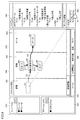
- FIG. 10 is a diagram showing a state in which the conditional branch node T2 is added to the protocol design window 530 of FIG.
- "conditional branching" is selected in the tool window 560 and dragged into the protocol design window 530.
- the conditional branch node T2 is added to the protocol design window 530.
- the user can specify the condition of the conditional branch node T2 in the information window 570.
- the condition can be entered as an equation or inequality, for example. From the conditional branch node T2, an edge E6 indicating that the condition of the conditional branch node T2 is satisfied and an edge E7 indicating that the condition is not satisfied extend. Each of the edges E6 and E7 is shown by a dotted line because the connection destination is undecided.
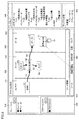
- FIG. 11 is a diagram showing a state in which the conditional branch processing of the conditional branch node T2 of FIG. 10 is confirmed.
- the position of the end node Me is moved from the position of the end node Me in FIG. 10, and the edge E2 is deleted.
- the edge E8 from the feature amount extraction node T1 to the conditional branch node T2 is added by the user's drag operation from the feature amount extraction node T1 to the conditional branch node T2.
- the edge E8 indicates that the condition related to the feature amount extracted by the process corresponding to the feature amount extraction node T1 is specified as the condition of the conditional branch node T2.
- the tip of the edge E6 is connected to the end node Me by the user's drag operation to the tip of the edge E6.
- the tip of the edge E7 is connected to the processing node M1 by the user's drag operation to the tip of the edge E7. Since the feature amount of the output data corresponding to the data node D1 can be directly used for the condition of the conditional branching node T2 via the feature amount extraction node T1, the design of the conditional branching process based on the output data is streamlined. be able to.
- the directed graph DG1 includes a loop structure that circulates in the order of the processing node M1, the data node D1, the feature amount extraction node T1, and the conditional branch node T2.
- the experimental protocol p1 ends. If the condition is not satisfied, the processing of each of the processing node M1 and the feature amount extraction node T1 is performed in this order, and then the conditional branching processing of the conditional branching node T2 is performed again. While the condition of the conditional branch node T2 is not satisfied, the processing of the processing node M1 and the feature quantity extraction node T1 is repeated.
- condition of the conditional branch node T2 is the end condition of the iterative processing including the processing of each of the processing node M1 and the feature quantity extraction node T1.
- the condition of the conditional branch node can also be used as the continuation condition of the iterative processing. In this case, the iterative processing is continued while the condition of the conditional branch node is satisfied.
- conditional branch processing node By including the conditional branch processing node in a plurality of nodes that can be selected as the vertices of the directed graph, the structure of the conditional branch processing and the structure of the iterative processing of the experimental protocol can be accurately reflected in the directed graph. As a result, it is possible to provide a method for designing an experimental protocol that can handle more advanced processing. In addition, by designing the experimental protocol in the form of a directed graph, it is possible to accurately perform automatic analysis of the experimental protocol, such as tracking the process of sample change in the experimental protocol. Examples of the process of sample change in the experimental protocol include the genealogy of cells formed by repeated seeding and subculture. Also, automatic analysis of experimental protocols includes machine learning for directed graphs (eg principal component analysis or deep learning).
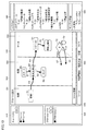
- FIG. 12 is a diagram showing a directed graph DG2 which is a design example of another experimental protocol p2. As shown in FIG. 12, “Protocol p2” is selected in the protocol list window 520.
- the directed graph DG2 includes a start node Ms2, an end node Me2, a processing node M21 corresponding to absorbance measurement, a timer node T22, a repeat node T23A, T23B, a container node C21, and a data node D21.
- the start node Ms2 and the repeat node T23A are connected by an edge E21 from the start node Ms2 to the repeat node T23A.
- the iterative node T23A and the processing node M21 are connected by an edge E22 from the iterative node T23A to the processing node M21.
- the container node C21 and the processing node M21 are connected by an edge E23 from the container node C21 to the processing node M21.
- the processing node M21 and the data node D21 are connected by an edge E24 from the processing node M21 to the data node D21.
- the processing node M21 and the timer node T22 are connected by an edge E25 from the processing node M21 toward the timer node T22.
- the timer node T22 and the iterative node T23B are connected by an edge E26 from the timer node T22 to the iterative node T23B.
- the iterative node T23B and the end node Me2 are connected by an edge E27 from the iterative node T23B to the end node Me2.
- the iterative nodes T23B and T23A are connected by an edge E28 from the iterative node T23B to T23A.
- the directed graph DG2 includes a loop structure that circulates in the order of the iterative node T23A, the processing node M21, the timer node T22, and the iterative node T23B.
- the upper limit of the number of iterations of the iteration process by the iteration nodes T23A and T23B is specified.
- the end condition of the iteration process is that the number of iterations is equal to or greater than the upper limit.
- the continuation condition of the iteration process is that the number of iterations is smaller than the upper limit. Iterative nodes can streamline the design of iterative processes in experimental protocols.
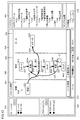
- FIG. 13 is a diagram showing a directed graph DG3 which is a design example of another experimental protocol p3.
- “Protocol p3” is selected in the protocol list window 520.
- the directed graph DG3 includes a start node Ms3, an end node Me3, a processing node M31, M32, M33, M34, M35, M36, a container node C31, C32, and a data node D31, D32.
- the processing nodes M31 to M36 are "culture of cells", “dispensing liquid”, “measurement of absorbance”, “centrifugation”, “dispensing liquid”, and “mass spectrometry” shown in the automated experimental system window 540. Corresponds to each.
- the start node Ms3 and the processing node M31 are connected by an edge E31 from the start node Ms3 to the processing node M31.
- the processing nodes M31 and M32 are connected by an edge E32 from the processing node M31 to M32.
- the processing nodes M32 and M33 are connected by an edge E33 from the processing node M32 to M33.
- the processing nodes M33 and M34 are connected by an edge E34 from the processing node M33 to M34.
- the processing nodes M34 and M35 are connected by an edge E35 from the processing node M34 to M35.
- the processing nodes M35 and M36 are connected by an edge E36 from the processing node M35 to M36.
- the processing node M36 and the end node Me3 are connected by an edge E37 from the processing node M36 to the end node Me.
- the container node C31 and the processing node M31 are connected by an edge E41 from the container node C31 to the processing node M31.
- the container node C31 and the processing node M32 are connected by an edge E42 from the container node C31 to the processing node M32.
- the container node C32 and the processing node M32 are connected by an edge E43 from the container node C32 to the processing node M32.
- the container node C32 and the processing node M33 are connected by an edge E44 from the container node C32 to the processing node M33.
- the container node C32 and the processing node M34 are connected by an edge E45 from the container node C32 to the processing node M34.
- the container node C32 and the processing node M35 are connected by an edge E46 from the container node C32 to the processing node M35.
- the container node C32 and the processing node M36 are connected by an edge E47 from the container node C32 to the processing node M36.
- the processing node M33 and the data node D31 are connected by an edge E51 from the processing node M33 to the data node D31.
- the processing node M36 and the data node D32 are connected by an edge E52 from the processing node M36 to the data node D32.
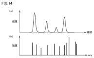
- FIG. 14 is a diagram showing an example of information displayed when a user performs a predetermined GUI operation (for example, double-clicking) on a node included in the directed graph DG3 shown in FIG.
- FIG. 14 shows an example of information displayed when the data node D32 (selected node) of FIG. 13 is double-clicked.
- 14 (a) and 14 (b) show liquid chromatograms and mass spectra generated from the output data of mass spectrometry corresponding to the processing node M36, respectively.
- a processing node is double-clicked, for example, a description of the processing corresponding to the processing node is displayed.
- a container node is double-clicked, for example, a detailed description of the samples contained in that container will be displayed.
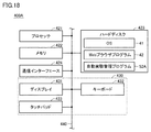
- FIG. 15 is a block diagram showing a hardware configuration of the server device 200 of FIG.
- the server device 200 includes a processor 201, a memory 202 as a storage unit, a hard disk 203, a communication interface 204 as a communication unit, and an input / output unit 205. These are communicably connected to each other via the bus 210.
- the hard disk 203 is a non-volatile storage device.
- an operating system (OS: Operating System) program 51 and an automated experiment management program 52 are stored in the hard disk 203.
- the hard disk 203 stores, for example, settings and outputs of various applications.
- the memory 202 is a volatile storage device, and includes, for example, a DRAM (Dynamic Random Access Memory).
- the processor 201 includes a CPU (Central Processing Unit).
- the processor 201 reads the program stored in the hard disk 203 into the memory 202 and executes it to realize various functions of the server device 200.
- the processor 201 that executes the automated experiment management program 52 provides the terminal device 400 with the experimental protocol design application 500.
- the processor 201 connects to the network NW via the communication interface 204.
- FIG. 16 is a flowchart illustrating a flow of an automatic experiment based on an experimental protocol performed in the automatic experiment management system 1000 of FIG.
- the terminal device 400 designs the experimental protocol in the form of a directed graph and transmits the experimental protocol to the server device 200.
- the server device 200 transmits the experimental protocol to the automated experimental system selected by the user of the terminal device 400.
- the control device of the automatic experiment system automatically executes the experiment protocol received from the server device 200 in S13.
- the control device transmits the output data of the process included in the experimental protocol in S14 to the server device 200.
- the experimental protocol designed in the terminal device is transmitted to the automated experiment system via the server device.
- the experimental protocol may be transmitted directly from the terminal device to the automated experimental system.
- FIG. 17 is a block diagram showing the configuration of the automated experiment management system 1100 according to the first modification of the embodiment.
- the configuration of the automated experiment management system 1100 is such that the server device 200 and the database 300 are removed from the automated experiment management system 1000 of FIG. 1, and the terminal device 400 is replaced with 400A. Other than these, the explanation is not repeated because it is the same.
- the experimental protocol design application 500A is displayed on the display 431 of the terminal device 400A.
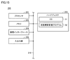
- FIG. 18 is a block diagram showing a hardware configuration of the terminal device 400A of FIG.
- the configuration of the terminal device 400A is such that the automatic experiment management program 52A is added to the hard disk 423 of FIG. Other than this, the explanation is not repeated because it is the same.
- the automatic experiment management program 52A By executing the automatic experiment management program 52A by the processor 421, automatic execution of the experimental protocol by the experimental protocol design application 500A and the automatic experiment system is realized.
- FIG. 19 is a block diagram showing the configuration of the automated experiment system 1B according to the second modification of the embodiment.
- the configuration of the automated experiment system 1B is such that the control device 110 is replaced with 110B in the automated experiment system 1 of FIG. Other than this, the explanation is not repeated because it is the same.
- the control device 110B includes an input / output unit 130 and a computer 140 (processing unit).
- the input / output unit 130 includes a display 131 (display unit), a keyboard 132 (input unit), and a mouse 133 (input unit).
- the display 131, the keyboard 132, and the mouse 133 are connected to the computer 140.
- the GUI of the experimental protocol design application 500B is displayed on the display 131.
- the keyboard 132 and mouse 133 accept GUI operations to the experimental protocol design application 500B by the user. That is, the user performs a desired GUI operation on the experimental protocol design application 500B by operating the keyboard 132 or the mouse 133 while referring to the display of the display 131.
- FIG. 20 is a block diagram showing a hardware configuration of the control device 110B of FIG.
- the computer 140 includes a processor 141, a memory 142 as a storage unit, a hard disk 143, and a communication interface 144. These are communicably connected to each other via bus 145.
- the hard disk 143 is a non-volatile storage device.
- an operating system (OS: Operating System) program 61 and an automated experiment management program 52B are stored in the hard disk 143.
- the hard disk 143 stores, for example, settings and outputs of various applications.
- the memory 142 is a volatile storage device, and includes, for example, a DRAM (Dynamic Random Access Memory).
- the processor 141 includes a CPU (Central Processing Unit).
- the processor 141 reads the program stored in the hard disk 143 into the memory 142 and executes it. By executing the automatic experiment management program 52B by the processor 141, automatic execution of the experimental protocol by the experimental protocol design application 500B and the plurality of experimental devices 120 is realized.
- the processor 141 connects to the network via the communication interface 144.
- the method according to one aspect is a step of accepting a GUI operation to a specific application by a user, and an experimental protocol in which the processing order of at least one experimental device is defined according to the accepted GUI operation in the form of a directed graph. It involves designing and controlling at least one experimental device to automatically execute the experimental protocol.
- the plurality of nodes that can be selected as the vertices of the directed graph include a processing node corresponding to each processing of at least one experimental device and a conditional branching node corresponding to the conditional branching processing.
- the plurality of nodes further include a container node, a data node, and a feature quantity extraction node.
- the container node corresponds to a container containing a sample processed by at least one experimental device.
- the data node corresponds to the output data of the process for each sample of at least one experimental device.
- the feature amount extraction node corresponds to the process of extracting the feature amount from the output data.
- the condition of the conditional branch node includes the condition regarding the feature quantity.
- the condition based on the output data can be used.
- the design of branch processing can be streamlined.
- the step of designing the experimental protocol in the form of a directed graph includes a step of automatically adding a container node and a data node with the addition of a processing node.
- the container node and the processing node are connected by a first edge from the container node to the processing node.
- the processing node and the data node are connected by a second edge from the processing node to the data node.
- the information about the selected node is displayed by a predetermined GUI operation for the selected node, so that the information of the components of the experimental protocol designed in the form of a directed graph is efficiently referred to. be able to.
- the plurality of nodes further include an iterative node corresponding to the iterative process.
- the iterative node can streamline the design of iterative processing in the experimental protocol.
- the system includes at least one experimental device, a terminal device, and a control device.
- the terminal device has an input unit and a processing unit.
- the input unit accepts a GUI operation for a specific application by a user.
- the processing unit designs an experimental protocol in the form of a directed graph in which the processing order of at least one experimental device is defined according to the received GUI operation.
- the control device controls at least one experimental device to execute the experimental protocol.
- the plurality of nodes that can be selected in the terminal device as the vertices of the directed graph include a processing node corresponding to each processing of at least one experimental device and a conditional branching node corresponding to the conditional branching processing.
- a server device that provides a specific application to the terminal device is further provided.
- the server device sends the experimental protocol designed in the terminal device to the control device.
- a plurality of server devices are interposed between a terminal device for designing an experimental protocol and a control device for controlling and executing at least one experimental device.
- the terminal device and a plurality of control devices can be collectively managed by the server device.
- the apparatus controls at least one experimental apparatus and executes an experimental protocol in which the processing order of at least one experimental apparatus is defined.
- the device includes a display unit, an input unit, and a processing unit.
- a specific application is displayed on the display unit.
- the input unit accepts a GUI operation for a specific application by a user.
- the processing unit designs the experimental protocol in the form of a directed graph according to the GUI operation.
- the plurality of nodes that can be selected as the vertices of the directed graph include a processing node corresponding to each processing of at least one experimental device and a conditional branching node corresponding to the conditional branching processing.
- 1,1B automatic experiment system 110,110B control device, 120 experimental device, 121 robot arm, 122 incubator, 123 liquid handler, 124 microplate reader, 125 centrifuge, 130,205,430 input / output unit, 131,431 Display, 132,432 keyboard, 133 mouse, 140 computer, 141,201,421 processor, 142,202,422 memory, 143,203,423 hard disk, 144,204,424 communication interface, 145,210,440 bus, 200 Server device, 300 database, 400, 400A terminal device, 433 touch pad, 500, 500A, 500B experimental protocol design application, 510 queue list window, 520 protocol list window, 530 protocol design window, 513 container area, 532 processing area, 533 Data area, 540 automatic experiment system window, 550 sample container window, 560 tool window, 570 information window, 600 Web browser, 1000, 1100 automatic experiment management system, C1, C21, C31, C32 container node, Cr selection cursor, D1, D21, D31, D32 data node
Landscapes
- Engineering & Computer Science (AREA)
- General Engineering & Computer Science (AREA)
- Theoretical Computer Science (AREA)
- Physics & Mathematics (AREA)
- General Physics & Mathematics (AREA)
- Software Systems (AREA)
- Human Computer Interaction (AREA)
- Databases & Information Systems (AREA)
- Analytical Chemistry (AREA)
- Immunology (AREA)
- Pathology (AREA)
- General Health & Medical Sciences (AREA)
- Health & Medical Sciences (AREA)
- Life Sciences & Earth Sciences (AREA)
- Chemical & Material Sciences (AREA)
- Biochemistry (AREA)
- Computer Networks & Wireless Communication (AREA)
- Signal Processing (AREA)
- Data Mining & Analysis (AREA)
- Computational Linguistics (AREA)
- Computer Hardware Design (AREA)
- Automatic Analysis And Handling Materials Therefor (AREA)
- Stored Programmes (AREA)
Priority Applications (4)
| Application Number | Priority Date | Filing Date | Title |
|---|---|---|---|
| JP2022533680A JP7494910B2 (ja) | 2020-06-30 | 2021-03-09 | 実験プロトコルを設計する方法、システム、および装置 |
| CN202180045972.0A CN115715388B (zh) | 2020-06-30 | 2021-03-09 | 设计实验协议的方法、系统及装置 |
| US18/013,411 US12352769B2 (en) | 2020-06-30 | 2021-03-09 | Method, system, and device for designing experimental protocol |
| JP2024065430A JP7652314B2 (ja) | 2020-06-30 | 2024-04-15 | 実験プロトコルを設計する方法 |
Applications Claiming Priority (2)
| Application Number | Priority Date | Filing Date | Title |
|---|---|---|---|
| JP2020-112661 | 2020-06-30 | ||
| JP2020112661 | 2020-06-30 |
Publications (1)
| Publication Number | Publication Date |
|---|---|
| WO2022004061A1 true WO2022004061A1 (ja) | 2022-01-06 |
Family
ID=79315708
Family Applications (1)
| Application Number | Title | Priority Date | Filing Date |
|---|---|---|---|
| PCT/JP2021/009166 Ceased WO2022004061A1 (ja) | 2020-06-30 | 2021-03-09 | 実験プロトコルを設計する方法、システム、および装置 |
Country Status (4)
| Country | Link |
|---|---|
| US (1) | US12352769B2 (https=) |
| JP (2) | JP7494910B2 (https=) |
| CN (1) | CN115715388B (https=) |
| WO (1) | WO2022004061A1 (https=) |
Cited By (1)
| Publication number | Priority date | Publication date | Assignee | Title |
|---|---|---|---|---|
| WO2023058384A1 (ja) * | 2021-10-06 | 2023-04-13 | 株式会社島津製作所 | 制御装置および方法 |
Families Citing this family (1)
| Publication number | Priority date | Publication date | Assignee | Title |
|---|---|---|---|---|
| WO2023047738A1 (ja) * | 2021-09-27 | 2023-03-30 | 株式会社島津製作所 | 複数の実験装置を制御する方法、システム、および装置 |
Citations (4)
| Publication number | Priority date | Publication date | Assignee | Title |
|---|---|---|---|---|
| US6594588B1 (en) * | 1998-05-18 | 2003-07-15 | Thermo Bio Analysis Corp. | Apparatus and method for monitoring and controlling laboratory information and/or instruments |
| WO2008014724A1 (en) * | 2006-07-28 | 2008-02-07 | Accelergy Shanghai R & D Center Co., Ltd. | Computer-aided graphical system, method and program product for designing experiment flow |
| JP2010518488A (ja) * | 2007-02-02 | 2010-05-27 | ベックマン・コールター・インコーポレーテッド | 検査室試験結果を自動検証するシステムおよび方法 |
| US20180253194A1 (en) * | 2017-03-03 | 2018-09-06 | Stratedigm, Inc. | Visual protocol designer |
Family Cites Families (15)
| Publication number | Priority date | Publication date | Assignee | Title |
|---|---|---|---|---|
| US7337440B1 (en) * | 1997-01-07 | 2008-02-26 | International Business Machines Corporation | Methodology for generating accessing functions for programmed execution of panel-driven business applications |
| US7216113B1 (en) * | 2000-03-24 | 2007-05-08 | Symyx Technologies, Inc. | Remote Execution of Materials Library Designs |
| US7850912B2 (en) * | 2003-05-14 | 2010-12-14 | Dako Denmark A/S | Method and apparatus for automated pre-treatment and processing of biological samples |
| CN101114315A (zh) * | 2006-07-28 | 2008-01-30 | 亚申科技研发中心(上海)有限公司 | 计算机辅助图形化实验设计系统及方法 |
| CN102317911B (zh) * | 2009-02-13 | 2016-04-06 | 起元技术有限责任公司 | 管理任务执行 |
| WO2010137077A1 (ja) | 2009-05-28 | 2010-12-02 | 株式会社島津製作所 | 分析装置制御プログラム作成支援システム及び該システム用プログラム |
| US9123002B2 (en) * | 2011-05-27 | 2015-09-01 | Abbott Informatics Corporation | Graphically based method for developing rules for managing a laboratory workflow |
| WO2016208623A1 (ja) | 2015-06-23 | 2016-12-29 | 国立研究開発法人 産業技術総合研究所 | 実験データ管理システム、方法、および、プログラム |
| AU2016287731B2 (en) * | 2015-06-30 | 2021-11-25 | Emerald Cloud Lab, Inc. | Laboratory experiment data exploration and visualization |
| US10756995B2 (en) * | 2015-07-27 | 2020-08-25 | Datagrid Systems, Inc. | Method, apparatus and system for real-time optimization of computer-implemented application operations using machine learning techniques |
| US10795935B2 (en) * | 2016-02-05 | 2020-10-06 | Sas Institute Inc. | Automated generation of job flow definitions |
| US11303651B1 (en) * | 2016-11-28 | 2022-04-12 | Palo Alto Networks, Inc. | Security appliance to monitor networked computing environment |
| US10338963B2 (en) * | 2017-05-10 | 2019-07-02 | Atlantic Technical Organization, Llc | System and method of schedule validation and optimization of machine learning flows for cloud computing |
| WO2018211617A1 (ja) * | 2017-05-17 | 2018-11-22 | 日本電気株式会社 | 実験計画最適化装置、実験計画最適化方法および実験計画最適化プログラム |
| US10873592B1 (en) * | 2019-12-23 | 2020-12-22 | Lacework Inc. | Kubernetes launch graph |
-
2021
- 2021-03-09 CN CN202180045972.0A patent/CN115715388B/zh active Active
- 2021-03-09 JP JP2022533680A patent/JP7494910B2/ja active Active
- 2021-03-09 US US18/013,411 patent/US12352769B2/en active Active
- 2021-03-09 WO PCT/JP2021/009166 patent/WO2022004061A1/ja not_active Ceased
-
2024
- 2024-04-15 JP JP2024065430A patent/JP7652314B2/ja active Active
Patent Citations (4)
| Publication number | Priority date | Publication date | Assignee | Title |
|---|---|---|---|---|
| US6594588B1 (en) * | 1998-05-18 | 2003-07-15 | Thermo Bio Analysis Corp. | Apparatus and method for monitoring and controlling laboratory information and/or instruments |
| WO2008014724A1 (en) * | 2006-07-28 | 2008-02-07 | Accelergy Shanghai R & D Center Co., Ltd. | Computer-aided graphical system, method and program product for designing experiment flow |
| JP2010518488A (ja) * | 2007-02-02 | 2010-05-27 | ベックマン・コールター・インコーポレーテッド | 検査室試験結果を自動検証するシステムおよび方法 |
| US20180253194A1 (en) * | 2017-03-03 | 2018-09-06 | Stratedigm, Inc. | Visual protocol designer |
Cited By (2)
| Publication number | Priority date | Publication date | Assignee | Title |
|---|---|---|---|---|
| WO2023058384A1 (ja) * | 2021-10-06 | 2023-04-13 | 株式会社島津製作所 | 制御装置および方法 |
| JPWO2023058384A1 (https=) * | 2021-10-06 | 2023-04-13 |
Also Published As
| Publication number | Publication date |
|---|---|
| JP2024096155A (ja) | 2024-07-12 |
| JP7652314B2 (ja) | 2025-03-27 |
| CN115715388A (zh) | 2023-02-24 |
| US20230251832A1 (en) | 2023-08-10 |
| US12352769B2 (en) | 2025-07-08 |
| JP7494910B2 (ja) | 2024-06-04 |
| JPWO2022004061A1 (https=) | 2022-01-06 |
| CN115715388B (zh) | 2026-04-24 |
Similar Documents
| Publication | Publication Date | Title |
|---|---|---|
| JP7652314B2 (ja) | 実験プロトコルを設計する方法 | |
| Kumar et al. | MEGA7: molecular evolutionary genetics analysis version 7.0 for bigger datasets | |
| Peri et al. | Read mapping and transcript assembly: a scalable and high-throughput workflow for the processing and analysis of ribonucleic acid sequencing data | |
| US20240080354A1 (en) | Providing bulk server-side custom actions for multiple rows of a client-side spread sheet | |
| Ko et al. | Closha: bioinformatics workflow system for the analysis of massive sequencing data | |
| JP7768239B2 (ja) | 実験プロトコルを管理する方法、システム、および装置 | |
| CN107657150A (zh) | 一种可视化生物信息分析工具生成方法和装置 | |
| Zhang et al. | IvoryOS: an interoperable web interface for orchestrating Python-based self-driving laboratories | |
| Mitra-Behura et al. | Singularity containers improve reproducibility and ease of use in computational image analysis workflows | |
| Thieme et al. | Deep integration of low-cost liquid handling robots in an industrial pharmaceutical development environment | |
| CN110781226B (zh) | 数据分析方法、装置、存储介质、设备及系统 | |
| Kao et al. | Browsing Multidimensional Molecular Networks with the Generic Network Browser (N‐Browse) | |
| Hung et al. | Cloud-enabled Biodepot workflow builder integrates image processing using Fiji with reproducible data analysis using Jupyter notebooks | |
| Melo et al. | SIGLa: an adaptable LIMS for multiple laboratories | |
| Muetze et al. | Using the contextual hub analysis tool (CHAT) in cytoscape to identify contextually relevant network hubs | |
| Laverick et al. | OT-Mation: an open-source code for parsing CSV files into Python scripts for control of OT-2 liquid-handling robotics | |
| US9727391B2 (en) | Method for performing task on unified information units in a personal workspace | |
| JP7622865B2 (ja) | 制御装置および方法 | |
| Lee et al. | iflow: A graphical user interface for flow cytometry tools in bioconductor | |
| He et al. | Biomedical application community based on China high-performance computing environment | |
| Watanabe et al. | Semi-automated image acquisition and analyses for broad users utilizing macro keyboards | |
| Yaroslavtsev et al. | Creating the Web Service of the Laboratory Information and Management System for Analytical Quality Control | |
| Chen et al. | PlantMDCS: A code-free, modular toolkit for rapid deployment of plant multi-omics databases | |
| US10452255B2 (en) | Logical set operations | |
| Lin et al. | peakScout–a user-friendly and reversible peak-to-gene translator for genomic peak calling results |
Legal Events
| Date | Code | Title | Description |
|---|---|---|---|
| 121 | Ep: the epo has been informed by wipo that ep was designated in this application |
Ref document number: 21832879 Country of ref document: EP Kind code of ref document: A1 |
|
| ENP | Entry into the national phase |
Ref document number: 2022533680 Country of ref document: JP Kind code of ref document: A |
|
| NENP | Non-entry into the national phase |
Ref country code: DE |
|
| 122 | Ep: pct application non-entry in european phase |
Ref document number: 21832879 Country of ref document: EP Kind code of ref document: A1 |
|
| WWG | Wipo information: grant in national office |
Ref document number: 18013411 Country of ref document: US |