WO2022003911A1 - ワークフロー整合性確保装置、ワークフロー整合性確保方法、および、ワークフロー整合性確保プログラム - Google Patents
ワークフロー整合性確保装置、ワークフロー整合性確保方法、および、ワークフロー整合性確保プログラム Download PDFInfo
- Publication number
- WO2022003911A1 WO2022003911A1 PCT/JP2020/026039 JP2020026039W WO2022003911A1 WO 2022003911 A1 WO2022003911 A1 WO 2022003911A1 JP 2020026039 W JP2020026039 W JP 2020026039W WO 2022003911 A1 WO2022003911 A1 WO 2022003911A1
- Authority
- WO
- WIPO (PCT)
- Prior art keywords
- workflow
- execution
- consistency
- control target
- unit
- Prior art date
Links
- 238000000034 method Methods 0.000 title claims description 27
- 238000012217 deletion Methods 0.000 claims description 29
- 230000037430 deletion Effects 0.000 claims description 29
- 238000012545 processing Methods 0.000 claims description 17
- 238000012546 transfer Methods 0.000 claims description 6
- 230000006870 function Effects 0.000 description 17
- 238000010586 diagram Methods 0.000 description 15
- 238000004891 communication Methods 0.000 description 4
- 230000000694 effects Effects 0.000 description 2
- 238000005516 engineering process Methods 0.000 description 2
- 238000010276 construction Methods 0.000 description 1
- 239000007787 solid Substances 0.000 description 1
- 239000013589 supplement Substances 0.000 description 1
Images


Classifications
-
- G—PHYSICS
- G06—COMPUTING; CALCULATING OR COUNTING
- G06Q—INFORMATION AND COMMUNICATION TECHNOLOGY [ICT] SPECIALLY ADAPTED FOR ADMINISTRATIVE, COMMERCIAL, FINANCIAL, MANAGERIAL OR SUPERVISORY PURPOSES; SYSTEMS OR METHODS SPECIALLY ADAPTED FOR ADMINISTRATIVE, COMMERCIAL, FINANCIAL, MANAGERIAL OR SUPERVISORY PURPOSES, NOT OTHERWISE PROVIDED FOR
- G06Q10/00—Administration; Management
- G06Q10/06—Resources, workflows, human or project management; Enterprise or organisation planning; Enterprise or organisation modelling
- G06Q10/063—Operations research, analysis or management
- G06Q10/0633—Workflow analysis
-
- G—PHYSICS
- G06—COMPUTING; CALCULATING OR COUNTING
- G06F—ELECTRIC DIGITAL DATA PROCESSING
- G06F11/00—Error detection; Error correction; Monitoring
- G06F11/30—Monitoring
-
- G—PHYSICS
- G06—COMPUTING; CALCULATING OR COUNTING
- G06F—ELECTRIC DIGITAL DATA PROCESSING
- G06F9/00—Arrangements for program control, e.g. control units
- G06F9/06—Arrangements for program control, e.g. control units using stored programs, i.e. using an internal store of processing equipment to receive or retain programs
- G06F9/46—Multiprogramming arrangements
- G06F9/54—Interprogram communication
- G06F9/542—Event management; Broadcasting; Multicasting; Notifications
Definitions
- the present invention relates to a workflow consistency ensuring device, a workflow consistency ensuring method, and a workflow consistency ensuring program.
- Patent Document 1 discloses a method of constructing a linked service by adding a new service or a new API by combining a catalog and an adapter.
- Patent Document 1 only discloses a method of linking services A, B, C, ..., When a failure occurs during processing of a workflow related to the service (for example, during construction of request service X). , There was a problem that the data consistency of the entire workflow could not be ensured.
- the present invention has been made in view of the above circumstances, and an object of the present invention is to provide a technique capable of ensuring data integrity of the entire workflow even if a failure occurs during the processing of workflows related to a plurality of services. It is to be.
- the workflow consistency ensuring device of one aspect of the present invention includes a storage unit that stores history information of the workflow execution state related to the control target controlled by the REST API (Representational State Transfer Application Programming Interface), and the history information from the storage unit. Is provided, the execution state of the workflow is periodically grasped by using the history information, and the control unit for deleting the control target related to the workflow whose execution state is a failure is provided.
- REST API Real State Transfer Application Programming Interface
- the workflow consistency ensuring device stores the history information of the workflow execution state regarding the control target controlled by the REST API (Representational State Transfer Application Programming Interface) in the storage unit.
- a step is performed, the history information is read from the storage unit, the execution state of the workflow is periodically grasped using the history information, and the control target related to the workflow whose execution state is a failure is deleted.
- the workflow consistency assurance program of one aspect of the present invention is a program that causes a computer to function as the workflow consistency assurance device.
- the data consistency of the entire workflow can be ensured.
- FIG. 1 is a reference diagram at the time of explaining the problem.
- FIG. 2 is a configuration diagram showing a configuration of a workflow consistency ensuring device.
- FIG. 3 is a diagram showing an example of parameters included in the workflow execution history management information.
- FIG. 4 is a diagram showing a specific example of the workflow execution process.
- FIG. 5A is a diagram showing a specific example of workflow execution history management information.
- FIG. 5B is a diagram showing a specific example of workflow execution history management information.
- FIG. 5C is a diagram showing a specific example of workflow execution history management information.
- FIG. 5D is a diagram showing a specific example of workflow execution history management information.
- FIG. 6 is a flow chart showing a new registration operation of the workflow execution history.
- FIG. 6 is a flow chart showing a new registration operation of the workflow execution history.
- FIG. 7 is a flow chart showing a change registration operation of the workflow execution history.
- FIG. 8 is a flow chart showing a failure registration operation of the workflow execution history.
- FIG. 9 is a flow diagram showing the operation of ensuring workflow consistency.
- FIG. 10 is a configuration diagram showing a hardware configuration of the workflow consistency ensuring device.
- the present invention relates to a technique for providing a request service X requested by a user.
- it is a technology that uses REST API (Representational State Transfer Application Programming Interface) to link multiple services A, B, C, etc. required to provide request service X.
- REST API Real-Time Transfer Application Programming Interface
- the workflow execution unit 1 uses the REST API to generate a generation request (POST / serviceA) for generating the service A. It sends to the server, sends a service B generation request (POST / serviceB) after the service A generation is completed, and sends a service C generation request (POST / serviceC) after the service B generation is completed. If a failure occurs at this timing, service C is not generated and request service X is not generated. On the other hand, service A and service B have been generated, and the data consistency cannot be ensured. In this case, it is necessary to delete service A and service B.
- the workflow execution unit 1 sends a deletion request (DELETE / serviceA) for deleting the service A to the server using the REST API. Then, after the deletion of service A is completed, the deletion request of service B (DELETE / serviceB) is sent, and after the deletion of service B is completed, the deletion request of service C (DELETE / serviceC) is sent. If a failure occurs at this timing, service C is not deleted and request service X is not deleted either. On the other hand, service A and service B have been deleted, and data consistency cannot be ensured. In this case, service C needs to be deleted.
- the execution history of the workflow executed by the workflow execution unit 1 is managed, and the execution state (completion, failure) of the workflow is periodically confirmed by using the execution history, and the execution state is caused by the occurrence of a failure. Is "failed" and the data of the resource where the data inconsistency has occurred is automatically deleted.
- the workflow identifier and the workflow execution time are taken into consideration when a failure occurs during workflow execution.
- the consistency of the workflow is ensured based on the execution history.
- FIG. 2 is a configuration diagram showing a configuration of the workflow consistency assurance device 2 according to the present embodiment.
- a workflow execution unit (execution unit) 1 that executes a workflow related to the controlled object 3 is also drawn.
- the control target 3 is a processing unit (entity of each processing, data group required for each processing) of each service A, B, C, ... Necessary for providing the request service X requested by the user.
- the workflow execution unit 1 has a function of accepting an application for request service X from the user terminal of the user and executing a workflow according to the type of application (generate, change, delete). For example, when the workflow execution unit 1 accepts the creation of the request service X, it uses the REST API to generate a plurality of services A, B, C, ... Required for providing the request service X so as to be able to cooperate with each other. do. When the workflow execution unit 1 accepts the deletion of the request service X, it deletes all the services A, B, C, ... Related to the request service X by using the REST API.
- the workflow execution unit 1 transmits a copy of the data processed at the time of workflow execution to the workflow consistency assurance device 2 as workflow execution history information, and registers it in the workflow history registration unit 21 of the workflow consistency assurance device 2. It has a function to do.
- the workflow consistency assurance device 2 includes a workflow history registration unit 21, a workflow history storage unit 22, and a workflow consistency assurance unit 23.
- the workflow history registration unit (registration unit) 21 has a function of receiving data duplication (history information) from the workflow execution unit 1 and registering it in the workflow history storage unit 22 as workflow execution history management information. At this time, the workflow history registration unit 21 executes a hidden registration process for registering the data from the workflow execution unit 1 in the workflow history storage unit 22 regardless of the workflow execution process of the workflow execution unit 1.
- the workflow execution unit 1 simply passes data to the workflow history registration unit 21, and is not aware of the registration process of the workflow history registration unit 21 (internal processing of the workflow consistency assurance device 2), so that "hidden registration” is performed. It becomes “processing".
- the workflow history storage unit (storage unit) 22 has a function of storing the workflow execution history management information registered by the workflow history registration unit 21. That is, the workflow history storage unit 22 stores the history information of the workflow execution state related to the control target 3 controlled by the workflow execution unit 1 by the REST API.
- FIG. 3 is a diagram showing an example of parameters included in the workflow execution history management information.
- the workflow execution history management information includes, for example, a "global identifier” that uniquely indicates the parent workflow in the upper row, a “local identifier” that uniquely indicates the child workflow in the lower row, and the execution status of the workflow (execution, completion, failure).
- "Execution state” indicating, "Execution API” indicating the content of the API executed for the control target 3
- "Delete API” for deleting the content of the execution API and the content of the API are in the control target 3.
- Control target reflection time indicating the reflected time
- Control target release time indicating the time when the API content is released from the control target 3 by change order, deletion order, etc.
- the API content is executed as an order
- the "system reflection time” indicating the time when the API was changed and the “system release time” indicating the time when the API contents were canceled as an order due to the execution of the change order, deletion order, etc. are saved in association with each other. These parameters are stored in the workflow execution history management information for each workflow.
- the workflow consistency assurance unit (control unit) 23 reads the workflow execution history management information from the workflow history storage unit 22, periodically confirms the workflow execution status using the read workflow execution history management information, and the execution status is changed. It has a function to delete the control target 3 related to the workflow which is "failure". Specifically, the workflow consistency assurance unit 13 searches for a workflow identifier (global identifier, local identifier) whose execution status is "failure” based on the workflow execution time (control target reflection time, system reflection time). Then, by acquiring and executing the deletion API corresponding to the identifier of the searched workflow, the control target 3 related to the workflow whose execution status is "failure" is deleted.
- a workflow identifier global identifier, local identifier
- the workflow history storage unit 22 performs a workflow based on the workflow identifier, the workflow execution state, the workflow execution time, the control target reflection time, and the deletion API for resolving the inconsistency. Since the workflow execution history by the execution unit 1 is managed and the workflow consistency assurance unit 23 deletes the control target 3 related to the workflow whose execution state is "failure", the data consistency can be ensured.
- deletion API is stored in the workflow execution history management information, it is possible to easily and surely delete the control target 3.
- a resource-oriented API such as REST API
- the workflow execution history related to the multi-stage workflow can be appropriately managed.
- information related to the time axis such as the control target reflection time and the control target release time indicating the reflection on the control target 3, the system reflection time and the system release time indicating the order execution, and the like are managed, so that the search is performed. You can easily search for the latest status based on the current time of the hour.
- FIG. 4 is a diagram showing a specific example of the workflow execution process.
- 5A to 5D are diagrams showing specific examples of workflow execution history management information updated according to the workflow execution process of FIG.
- the workflow is divided into two stages: a global workflow that generates both services A and service B to generate the request service X, and a local workflow that generates each of service A and service B. It shall be.
- the workflow hierarchy is not limited to two stages, and may be three or more stages.
- the "service” is a service actually used by the user. For example, subscribing to an electronic magazine.
- the "order” is to input various necessary settings to the server or computer system so that the "service” requested by the user can be provided.
- Step S1 When the request service X is applied by the user, the global workflow execution unit 11 of the workflow execution unit 1 generates the request service X (POST / serviceX). At this time, the workflow history registration unit 21 of the workflow consistency ensuring device 2 puts the workflow execution history management information on the first line.
- Step S3 Next, the global workflow execution unit 11 executes order A-1 (POST / A-1) from the service A generation function 121 to the service A, and normally responds from the service A to the execution of the order A-1. Will be notified that has been returned.
- the workflow history registration unit 21 sets the workflow execution history management information on the third line.
- Step S4 Next, in the global workflow execution unit 11, the service A generation function 121 executes the order A-2 (POST / A-2) for the service A, and the service A normally responds to the execution of the order A-2. Will be notified that has been returned. At this time, the workflow history registration unit 21 sets the workflow execution history management information on the fourth line.
- the workflow history registration unit 21 sets the workflow execution history management information on the fifth line.
- Step S6 Next, the global workflow execution unit 11 calls the service B generation function 122 of the local workflow execution unit 12, and causes the called service B generation function 122 to execute the generation workflow to the service B (POST / serviceB). At this time, the workflow history registration unit 21 sets the workflow execution history management information on the sixth line.
- Step S7 Next, in the global workflow execution unit 11, the service B generation function 122 executes the order B-1 (POST / B-1) to the service B, and the service B normally responds to the execution of the order B-1. Will be notified that has been returned. At this time, the workflow history registration unit 21 sets the workflow execution history management information on the seventh line.
- the service B generation function 122 executes the order B-1 (POST / B-1) to the service B, and the service B normally responds to the execution of the order B-1. Will be notified that has been returned.
- the workflow history registration unit 21 sets the workflow execution history management information on the seventh line.
- the workflow consistency ensuring unit 23 acquires and executes the deletion API necessary for ensuring data consistency from the workflow execution history management information, so that the order A-1, the order A-2, the service A, and the order B- Delete 1 This ensures data integrity for request service X.
- Workflow execution history management information is managed on a time axis and workflow execution status (execution, completion, failure), and data consistency can be ensured by executing the subsequent steps based on these.
- Step 5 the workflow consistency assurance unit 23 executes the deletion API of "service A” acquired in step 2, and executes the deletion API of "order B-1" acquired in step 4.
- order A-1, order A-2, service A, and order B-1 are deleted, so that the data inconsistency is resolved.
- workflow history registration unit 21 hides these processes and registers the workflow execution history according to the types of new registration / change / failure.
- workflow execution unit 1 does not need to be aware of the internal processing of the workflow history registration unit 21.
- the workflow execution unit 1 simply passes a copy of the data processed at the time of workflow execution to the workflow history registration unit 21, and the process for ensuring data consistency is a workflow consistency that is a different processing entity from the workflow execution unit 1. This is performed by the securing device 2.
- the workflow execution unit 1 can focus on the workflow execution process, and is freed from the troublesome need to perform the data consistency assurance process.
- FIG. 6 is a flow chart showing a new registration operation of the workflow execution history.
- Step S101 The workflow history registration unit 21 receives the "global identifier", "local identifier”, “execution state”, “execution API”, and “deletion API” as input information from the workflow execution unit 1.
- Step S102 Next, the workflow history registration unit 21 determines whether or not the "execution state" of the input information is "execution”. If the "execution state" is "execution”, the process proceeds to step S103. If the "execution state” is not "execution", the process proceeds to step S104.
- Step S103 When the "execution state" of the input information is "execution", the workflow history registration unit 21 automatically adds the "current time” to the “system reflection time”, and “control target reflection time” and “control target cancellation”. "Infinity” is automatically added to "Time” and "System release time”. Then, the process proceeds to step S105.
- Step S104 When the "execution status" of the input information is not “execution”, the workflow history registration unit 21 automatically adds the "current time” to the "control target reflection time” and “system reflection time”, and “control target release time”. , "Infinity” is automatically added to "System release time”. Then, the process proceeds to step S105.
- Step S105 Finally, the workflow history registration unit 21 adds the input information automatically added in step S103 or step S104 to the last line of the workflow execution history management information.
- FIG. 7 is a flow chart showing a change registration operation of the workflow execution history.
- Step S201 The workflow history registration unit 21 receives the "global identifier", "local identifier”, “execution state”, “execution API”, and “deletion API” as input information from the workflow execution unit 1.
- Step S202 Next, in the workflow history registration unit 21, the record in which the "global identifier" of the workflow execution history management information matches the "global identifier" of the input information and the "system reflection time” of the workflow execution history management information is the latest time. To get.
- Step S203 Next, the workflow history registration unit 21 automatically adds the "current time” to the "system release time” of the acquired record, and invalidates the record.
- Step S204 the workflow history registration unit 21 automatically adds the "current time” to the "control target reflection time” and “system reflection time” to the input information in step S201, and then adds the "control target release time” and "system”. "Infinity” is automatically added to "Release time”.
- Step S205 Finally, the workflow history registration unit 21 adds the input information that has been automatically added to the last line of the workflow execution history management information.
- FIG. 8 is a flow chart showing a failure registration operation of the workflow execution history.
- Step S301 The workflow history registration unit 21 receives the "global identifier”, "local identifier”, “execution state”, “execution API”, and “deletion API” as input information from the workflow execution unit 1.
- Step S302 the workflow history registration unit 21 automatically adds the "current time” to the “system reflection time” and adds "Infinity” to the "control target reflection time”, “control target cancellation time”, and "system cancellation time”. Add automatically.
- Step S303 Next, the workflow history registration unit 21 adds the input information that has been automatically added to the last line of the workflow execution history management information.
- Step S304 Next, the workflow history registration unit 21 acquires a record in which the "global identifier" of the input information is designated as the "local identifier" of the workflow execution history management information.
- Step S305 Next, the workflow history registration unit 21 automatically adds the "current time” to the "system release time” of the acquired record, and invalidates the record.
- Step S306 the workflow history registration unit 21 duplicates the invalidated record, updates the "execution status" to “failure”, updates the "system reflection time” to "current time”, and executes the workflow as a new record. Add to the last line of history management information.
- Step S307 the workflow history registration unit 21 acquires a record in which the "global identifier" or “local identifier” of the workflow execution history management information is "null", and adds the "current time” as the "system release time”. Invalidate the record.
- Step S308 the workflow history registration unit 21 duplicates the record invalidated in step S307, updates the "execution status" to "failure", updates the "system reflection time” to "current time”, and updates the new record. Add to the last line of workflow execution history management information.
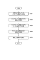
- FIG. 9 is a flow diagram showing the operation of ensuring workflow consistency.
- the following steps S401 to S405 correspond to the above procedures 1 to 5, respectively.
- Step S401 From the workflow execution history management information, the workflow consistency assurance unit 23 determines that the "local identifier" is “null”, the "execution status” is “failure”, the "system reflection time” is before the “current time”, and the “system is canceled”. Get the global identifier after "time” is "current time”.
- Step S402 the workflow consistency assurance unit 23 matches the global identifier acquired by the "global identifier" from the workflow execution history management information, the "control target reflection time” is before the "current time”, and the "system release time”. Get the deletion API included in the records after "current time”.
- Step S403 Next, in the workflow consistency assurance unit 23, from the workflow execution history management information, the "global identifier" matches the global identifier acquired in step S401, and the "control target reflection time” is "current time” or later, "system release”. Gets the local identifier contained in the record whose "time” is after the "current time”.
- Step S404 Next, in the workflow consistency assurance unit 23, from the workflow execution history management information, the "global identifier" matches the local identifier acquired in step S403, and the "control target reflection time” is before the "current time", ". Get the deletion API included in the record whose "system release time” is after "current time”.
- Step S405 Finally, the workflow consistency ensuring unit 23 executes the deletion API acquired in step S402 and step S404, respectively. This can eliminate the data inconsistency.
- the workflow consistency assurance device 2 has a workflow history storage unit 22 for storing workflow execution history management information of a workflow execution state related to a control target controlled by the REST API, and a workflow from the workflow history storage unit 22.
- the workflow consistency assurance unit 23 which reads out the execution history management information, periodically grasps the execution state of the workflow using the workflow execution history management information, and deletes the control target 3 related to the workflow whose execution state is unsuccessful. Therefore, even if a failure occurs during the processing of the workflow related to a plurality of services, the data consistency of the entire workflow can be ensured.
- the present invention is not limited to the above embodiment.
- the present invention can be modified in a number of ways within the scope of the gist of the present invention.
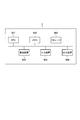
- the workflow consistency ensuring device 2 of the present embodiment described above has, for example, as shown in FIG. 10, a CPU (Central Processing Unit, processor) 901, a memory 902, and a storage (HDD: Hard Disk Drive, SSD: Solid). It can be realized by using a general-purpose computer system including a StateDrive) 903, a communication device 904, an input device 905, and an output device 906.
- the memory 902 and the storage 903 are storage devices.
- each function of the workflow consistency ensuring device 2 is realized by executing a predetermined program loaded on the memory 902 by the CPU 901.
- the workflow consistency assurance device 2 may be implemented on one computer.
- the workflow consistency ensuring device 2 may be implemented by a plurality of computers.
- the workflow consistency ensuring device 2 may be a virtual machine mounted on a computer.
- the program for the workflow consistency assurance device 2 can be stored in a computer-readable recording medium such as HDD, SSD, USB (Universal Serial Bus) memory, CD (Compact Disc), DVD (Digital Versatile Disc).
- the program for the workflow consistency ensuring device 2 can also be distributed via the communication network.
Abstract
ワークフロー整合性確保装置2は、REST APIで制御する制御対象に関するワークフローの実行状態のワークフロー実行履歴管理情報を記憶するワークフロー履歴保存部22と、ワークフロー履歴保存部22からワークフロー実行履歴管理情報を読み出して、ワークフロー実行履歴管理情報を用いてワークフローの実行状態を定期的に把握し、実行状態が失敗であるワークフローに関する制御対象3を削除するワークフロー整合性確保部23と、を備える。
Description
本発明は、ワークフロー整合性確保装置、ワークフロー整合性確保方法、および、ワークフロー整合性確保プログラムに関する。
ユーザから申し込まれた要求サービスXの実態を複数のサービスA,B,C,…を連携させることで構築する方法が知られている。具体的には、REST API(Representational State Transfer Application Programming Interface)のようなリソース志向型APIを用い、複数のサービスA,B,C,…を生成して連携させることで、要求サービスXをユーザへ提供する。例えば、特許文献1には、カタログとアダプタとの組み合わせにより、新サービスや新APIを追加して連携サービスを構築する方法が開示されている。
しかしながら、特許文献1は、サービスA,B,C,…間の連携方法を開示するにすぎないため、そのサービスに関するワークフローの処理中(例えば、要求サービスXの構築中)に障害が発生した場合、ワークフロー全体のデータ整合性を確保できないという課題があった。
本発明は、上記事情に鑑みてなされたものであり、本発明の目的は、複数のサービスに関するワークフローの処理中に障害が発生した場合でも、ワークフロー全体のデータ整合性を確保可能な技術を提供することである。
本発明の一態様のワークフロー整合性確保装置は、REST API(Representational State Transfer Application Programming Interface)で制御する制御対象に関するワークフローの実行状態の履歴情報を記憶する記憶部と、前記記憶部から前記履歴情報を読み出し、前記履歴情報を用いてワークフローの実行状態を定期的に把握し、実行状態が失敗であるワークフローに関する制御対象を削除する制御部と、を備える。
本発明の一態様のワークフロー整合性確保方法は、前記ワークフロー整合性確保装置が、REST API(Representational State Transfer Application Programming Interface)で制御する制御対象に関するワークフローの実行状態の履歴情報を記憶部に記憶するステップと、前記記憶部から前記履歴情報を読み出し、前記履歴情報を用いてワークフローの実行状態を定期的に把握し、実行状態が失敗であるワークフローに関する制御対象を削除するステップと、を行う。
本発明の一態様のワークフロー整合性確保プログラムは、上記ワークフロー整合性確保装置として、コンピュータを機能させるプログラムである。
本発明によれば、複数のサービスに関するワークフローの処理中に障害が発生した場合でも、ワークフロー全体のデータ整合性を確保できる。
以下、図面を参照して、本発明の実施形態を説明する。図面の記載において同一部分には同一符号を付し説明を省略する。
[1.発明の概要]
本発明は、ユーザから申し込まれた要求サービスXを提供する技術に関する。特に、REST API(Representational State Transfer Application Programming Interface)を用いて、要求サービスXを提供するために必要な複数のサービスA,B,C,…を連携させる技術である。
本発明は、ユーザから申し込まれた要求サービスXを提供する技術に関する。特に、REST API(Representational State Transfer Application Programming Interface)を用いて、要求サービスXを提供するために必要な複数のサービスA,B,C,…を連携させる技術である。
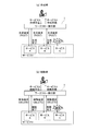
従来技術では、上記課題欄で説明した通り、複数のサービスA,B,C,に関するワークフローの処理中に障害が発生した場合、ワークフロー全体のデータ整合性を確保できない。具体的には、図1(a)に示すように、要求サービスXを作成する場合、ワークフロー実行部1は、REST APIを用いて、サービスAを生成するための生成要求(POST/serviceA)をサーバへ送信し、サービスAの生成完了後にサービスBの生成要求(POST/serviceB)を送信し、サービスBの生成完了後にサービスCの生成要求(POST/serviceC)を送信する。このタイミングで障害が発生すると、サービスCは生成されず、要求サービスXも生成されない。一方、サービスA及びサービスBは生成されており、データ整合性が確保できていない状態になる。この場合、サービスA及びサービスBの削除が必要である。
また、図1(b)に示すように、要求サービスXを削除する場合、ワークフロー実行部1は、REST APIを用いて、サービスAを削除するための削除要求(DELETE/serviceA)をサーバへ送信し、サービスAの削除完了後にサービスBの削除要求(DELETE/serviceB)を送信し、サービスBの削除完了後にサービスCの削除要求(DELETE/serviceC)を送信する。このタイミングで障害が発生すると、サービスCは削除されず、要求サービスXも削除されない。一方、サービスA及びサービスBは削除されており、データ整合性が確保できていない状態になる。この場合、サービスCの削除が必要である。
そこで、本発明は、ワークフロー実行部1が実行するワークフローの実行履歴を管理するとともに、その実行履歴を用いてワークフローの実行状態(完了、失敗)を定期的に確認し、障害の発生により実行状態が「失敗」となりデータ不整合が発生しているリソースのデータを自動で削除する。具体的には、制御対象(サービスA,B,C,…の処理部)に関して実行したワークフローの実行履歴の内容について、ワークフロー実行時の障害発生を考慮して、ワークフローの識別子、ワークフローの実行時刻、不整合を解消させるための削除APIなどを基に、その実行履歴を管理する。また、その実行履歴を基に、ワークフローの整合性を確保する。
[2.ワークフロー整合性確保装置の構成]
[2.1.ワークフロー整合性確保装置の構成例]
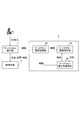
図2は、本実施形態に係るワークフロー整合性確保装置2の構成を示す構成図である。図2には、制御対象3に関するワークフローを実行するワークフロー実行部(実行部)1も併せて描画している。制御対象3とは、ユーザから申し込まれた要求サービスXを提供するために必要な各サービスA,B,C,…の処理部(各処理の実体、各処理に必要なデータ群)である。
[2.1.ワークフロー整合性確保装置の構成例]
図2は、本実施形態に係るワークフロー整合性確保装置2の構成を示す構成図である。図2には、制御対象3に関するワークフローを実行するワークフロー実行部(実行部)1も併せて描画している。制御対象3とは、ユーザから申し込まれた要求サービスXを提供するために必要な各サービスA,B,C,…の処理部(各処理の実体、各処理に必要なデータ群)である。
ワークフロー実行部1は、ユーザのユーザ端末から要求サービスXの申し込みを受け付け、申し込みの種別(生成、変更、削除)に応じたワークフローを実行する機能を備える。例えば、ワークフロー実行部1は、要求サービスXの作成を受け付けた場合、REST APIを用いて、その要求サービスXを提供するために必要な複数のサービスA,B,C,…を連携可能に生成する。ワークフロー実行部1は、要求サービスXの削除を受け付けた場合、REST APIを用いて、その要求サービスXに係る全てのサービスA,B,C,…を削除する。
本実施形態において、ワークフロー実行部1は、ワークフロー実行時に処理したデータの複製をワークフロー実行の履歴情報としてワークフロー整合性確保装置2へ送信し、ワークフロー整合性確保装置2のワークフロー履歴登録部21に登録する機能を備えている。
次に、ワークフロー整合性確保装置2について説明する。ワークフロー整合性確保装置2は、図2に示したように、ワークフロー履歴登録部21と、ワークフロー履歴保存部22と、ワークフロー整合性確保部23と、を備える。
ワークフロー履歴登録部(登録部)21は、ワークフロー実行部1からデータの複製(履歴情報)を受信し、ワークフロー実行履歴管理情報としてワークフロー履歴保存部22に登録する機能を備える。このとき、ワークフロー履歴登録部21は、ワークフロー実行部1のワークフロー実行処理とは無関係にワークフロー実行部1からのデータをワークフロー履歴保存部22に登録する隠蔽的な登録処理を実行する。ワークフロー実行部1としては、単にデータをワークフロー履歴登録部21に渡すだけであり、ワークフロー履歴登録部21の登録処理(ワークフロー整合性確保装置2の内部処理)を意識しないので、「隠蔽的な登録処理」となる。
ワークフロー履歴保存部(記憶部)22は、ワークフロー履歴登録部21により登録されたワークフロー実行履歴管理情報を記憶する機能を備える。つまり、ワークフロー履歴保存部22は、ワークフロー実行部1がREST APIで制御する制御対象3に関するワークフローの実行状態の履歴情報を記憶する。
図3は、ワークフロー実行履歴管理情報に含まれるパラメータ例を示す図である。ワークフロー実行履歴管理情報には、例えば、上段の親ワークフローを一意に示す「グローバル識別子」と、下段の子ワークフローを一意に示す「ローカル識別子」と、ワークフローの実行状態(実行中、完了、失敗)を示す「実行状態」と、制御対象3に対して実行したAPIの内容を示す「実行API」と、実行APIの内容を削除するための「削除API」と、APIの内容が制御対象3に反映された時刻を示す「制御対象反映時刻」と、APIの内容が変更オーダ、削除オーダ等により制御対象3から解除された時刻を示す「制御対象解除時刻」と、APIの内容がオーダとして実行された時刻を示す「システム反映時刻」と、APIの内容が変更オーダ、削除オーダ等が実行されたことによりオーダとして解除された時刻を示す「システム解除時刻」と、が関連付けて保存される。ワークフロー実行履歴管理情報には、これらのパラメータがワークフロー毎に保存される。
ワークフロー整合性確保部(制御部)23は、ワークフロー履歴保存部22からワークフロー実行履歴管理情報を読み出し、読み出したワークフロー実行履歴管理情報を用いてワークフローの実行状態を定期的に確認し、実行状態が「失敗」であるワークフローに関する制御対象3を削除する機能を備える。具体的には、ワークフロー整合性確保部13は、実行状態が「失敗」であるワークフローの識別子(グローバル識別子、ローカル識別子)をワークフローの実行時刻(制御対象反映時刻、システム反映時刻)を基に検索し、検索したワークフローの識別子に対応する削除APIを取得して実行することで、実行状態が「失敗」であるワークフローに関する制御対象3を削除する。
[2.2.ワークフロー整合性確保装置の構成による効果]
本実施形態では、ワークフロー履歴保存部22が、ワークフローの識別子と、ワークフローの実行状態と、ワークフローの実行時刻及び制御対象反映の時刻と、不整合を解消するための削除APIとを基に、ワークフロー実行部1によるワークフロー実行履歴を管理し、ワークフロー整合性確保部23が、実行状態が「失敗」であるワークフローに関する制御対象3を削除するので、データ整合性を確保できる。
本実施形態では、ワークフロー履歴保存部22が、ワークフローの識別子と、ワークフローの実行状態と、ワークフローの実行時刻及び制御対象反映の時刻と、不整合を解消するための削除APIとを基に、ワークフロー実行部1によるワークフロー実行履歴を管理し、ワークフロー整合性確保部23が、実行状態が「失敗」であるワークフローに関する制御対象3を削除するので、データ整合性を確保できる。
特に、ワークフロー実行履歴管理情報に削除APIを格納するので、制御対象3の削除が容易かつ確実に実現可能となる。なお、REST APIのようなリソース志向型APIの場合、生成リソースに対応した削除用APIが既に存在しており、その削除用APIをそのまま活用可能である。
また、本実施形態では、グローバル識別子とローカル識別子との階層的な識別子を用いるので、ワークフローが階層的な多段構成であっても、その多段構成のワークフローに関するワークフロー実行履歴を適切に管理できる。
さらに、本実施形態では、制御対象3への反映を表す制御対象反映時刻や制御対象解除時刻、オーダ実行を表すシステム反映時刻やシステム解除時刻など、時間軸に関する情報を含めて管理するので、検索時の現在時刻を基に最新の状態を容易に検索できる。
[3.ワークフロー整合性確保装置の動作]
[3.1.ワークフロー実行履歴管理の具体例]
図4は、ワークフロー実行処理の具体例を示す図である。図5A~図5Dは、図4のワークフロー実行処理に応じて更新されるワークフロー実行履歴管理情報の具体例を示す図である。この実施例では、サービスAとサービスBで構成される要求サービスXを生成する場合を例に説明する。また、ワークフローは、要求サービスXを生成するためにサービスAとサービスBの両方のサービスを生成するグローバルワークフローと、サービスAとサービスBのそれぞれを生成するローカルワークフローと、の2段に分かれているものとする。ワークフローの階層は、2段に限らず、3段以上でもよい。
[3.1.ワークフロー実行履歴管理の具体例]
図4は、ワークフロー実行処理の具体例を示す図である。図5A~図5Dは、図4のワークフロー実行処理に応じて更新されるワークフロー実行履歴管理情報の具体例を示す図である。この実施例では、サービスAとサービスBで構成される要求サービスXを生成する場合を例に説明する。また、ワークフローは、要求サービスXを生成するためにサービスAとサービスBの両方のサービスを生成するグローバルワークフローと、サービスAとサービスBのそれぞれを生成するローカルワークフローと、の2段に分かれているものとする。ワークフローの階層は、2段に限らず、3段以上でもよい。
ここで、サービスとオーダについて補足しておく。「サービス」とは、ユーザが実際に利用するサービスである。例えば、電子雑誌の購読などである。「オーダ」とは、ユーザが申し込んだ「サービス」を提供可能となるように、サーバやコンピュータシステムに様々な必要な設定を投入することである。
ステップS1;
ユーザから要求サービスXの申し込みが行われると、ワークフロー実行部1のグローバルワークフロー実行部11は、要求サービスXを生成(POST/serviceX)する。このとき、ワークフロー整合性確保装置2のワークフロー履歴登録部21は、ワークフロー実行履歴管理情報の1行目に、
「グローバル識別子」に“1111”(=要求サービスXの識別子)、
「ローカル識別子」に“null”、
「実行状態」に“実行中”、
「実行API」に“POST/serviceX”、
「削除API」に“-”
「制御対象反映時刻」に“Infinity”、
「制御対象解除時刻」に“Infinity”、
「システム反映時刻」に“2020/3/30 10:00:00”(=現在時刻)、
「システム解除時刻」に“Infinity”、
を登録する。
ステップS2;
次に、グローバルワークフロー実行部11は、ローカルワークフロー実行部12のサービスA生成機能121を呼び出し、呼び出したサービスA生成機能121にサービスAへの生成ワークフローを実行(POST/serviceA)させる。このとき、ワークフロー履歴登録部21は、ワークフロー実行履歴管理情報の2行目に、
「グローバル識別子」に“1111”(=要求サービスXの識別子)、
「ローカル識別子」に“2222”(=サービスAの識別子)、
「実行状態」に“実行中”、
「実行API」に“POST/serviceA”、
「削除API」に“-”
「制御対象反映時刻」に“Infinity”、
「制御対象解除時刻」に“Infinity”、
「システム反映時刻」に“2020/3/30 10:00:30”(=現在時刻)、
「システム解除時刻」に“Infinity”、
を登録する。
ステップS3;
次に、グローバルワークフロー実行部11は、サービスA生成機能121から、サービスAに対してオーダA-1が実行(POST/A-1)され、そのオーダA-1の実行についてサービスAから正常応答が返却されたことが通知される。このとき、ワークフロー履歴登録部21は、ワークフロー実行履歴管理情報の3行目に、
「グローバル識別子」に“2222”(=サービスAの識別子)、
「ローカル識別子」に“3333”(=オーダA-1の識別子)、
「実行状態」に“完了”、
「実行API」に“POST/A-1”、
「削除API」に“DELETE/A-1/3333”
「制御対象反映時刻」に“2020/3/30 10:01:00”(=現在時刻)、
「制御対象解除時刻」に“Infinity”、
「システム反映時刻」に“2020/3/30 10:01:00”(=現在時刻)、
「システム解除時刻」に“Infinity”、
を登録する。「削除API」の“DELETE/A-1/3333”は、オーダA-1を削除するためのAPIである。この削除APIを実行することでオーダA-1を削除できる。
ステップS4;
次に、グローバルワークフロー実行部11は、サービスA生成機能121から、サービスAに対してオーダA-2が実行(POST/A-2)され、そのオーダA-2の実行についてサービスAから正常応答が返却されたことが通知される。このとき、ワークフロー履歴登録部21は、ワークフロー実行履歴管理情報の4行目に、
「グローバル識別子」に“2222”(=サービスAの識別子)、
「ローカル識別子」に“4444”(=オーダA-2の識別子)、
「実行状態」に“完了”、
「実行API」に“POST/A-2”、
「削除API」に“DELETE/A-2/4444”
「制御対象反映時刻」に“2020/3/30 10:02:00”(=現在時刻)、
「制御対象解除時刻」に“Infinity”、
「システム反映時刻」に“2020/3/30 10:02:00”(=現在時刻)、
「システム解除時刻」に“Infinity”、
を登録する。「削除API」の“DELETE/A-1/4444”は、オーダA-2を削除するためのAPIである。この削除APIを実行することでオーダA-2を削除できる。
ステップS5;
ステップS4により、サービスAの生成が完了する。このとき、ワークフロー履歴登録部21は、ワークフロー実行履歴管理情報の5行目に、
「グローバル識別子」に“1111”(=要求サービスXの識別子)、
「ローカル識別子」に“2222”(=サービスAの識別子)、
「実行状態」に“完了”、
「実行API」に“POST/serviceA”、
「削除API」に“DELETE/serviceA/2222”
「制御対象反映時刻」に“2020/3/30 10:02:30”(=現在時刻)、
「制御対象解除時刻」に“Infinity”、
「システム反映時刻」に“2020/3/30 10:02:30”(=現在時刻)、
「システム解除時刻」に“Infinity”、
を登録する。「削除API」の“DELETE/serviceA/2222”は、サービスAを削除するためのAPIである。この削除APIを実行することで、サービスA及び当該サービスAに紐づく全てのオーダ(オーダA-1及びオーダA-2)を削除できる。また、サービスAの生成処理に関する2行目のレコードの「システム解除時刻」にも“2020/3/30 10:02:30”(=現在時刻)が登録される。
ステップS6;
次に、グローバルワークフロー実行部11は、ローカルワークフロー実行部12のサービスB生成機能122を呼び出し、呼び出したサービスB生成機能122にサービスBへの生成ワークフローを実行(POST/serviceB)させる。このとき、ワークフロー履歴登録部21は、ワークフロー実行履歴管理情報の6行目に、
「グローバル識別子」に“1111”(=要求サービスXの識別子)、
「ローカル識別子」に“5555”(=サービスBの識別子)、
「実行状態」に“実行中”、
「実行API」に“POST/serviceB”、
「削除API」に“-”
「制御対象反映時刻」に“Infinity”、
「制御対象解除時刻」に“Infinity”、
「システム反映時刻」に“2020/3/30 10:03:00”(=現在時刻)、
「システム解除時刻」に“Infinity”、
を登録する。
ステップS7;
次に、グローバルワークフロー実行部11は、サービスB生成機能122から、サービスBに対してオーダB-1が実行(POST/B-1)され、そのオーダB-1の実行についてサービスBから正常応答が返却されたことが通知される。このとき、ワークフロー履歴登録部21は、ワークフロー実行履歴管理情報の7行目に、
「グローバル識別子」に“5555”(=サービスBの識別子)、
「ローカル識別子」に“6666”(=オーダB-1の識別子)、
「実行状態」に“完了”、
「実行API」に“POST/B-1”、
「削除API」に“DELETE/B-1/6666”
「制御対象反映時刻」に“2020/3/30 10:03:30”(=現在時刻)、
「制御対象解除時刻」に“Infinity”、
「システム反映時刻」に“2020/3/30 10:03:30”(=現在時刻)、
「システム解除時刻」に“Infinity”、
を登録する。“「削除API」のDELETE/B-1/6666”は、オーダB-1を削除するためのAPIである。この削除APIを実行することでオーダB-1を削除できる。
ステップS8;
次に、グローバルワークフロー実行部11は、サービスB生成機能122により、サービスBに対してオーダB-2が実行(POST/B-2)されるが、通信障害により当該実行は失敗する。このとき、ワークフロー履歴登録部21は、ワークフロー実行履歴管理情報の8行目に、
「グローバル識別子」に“5555”(=サービスBの識別子)、
「ローカル識別子」に“7777”(=オーダB-2の識別子)、
「実行状態」に“失敗”、
「実行API」に“POST/B-2”、
「削除API」に“-”
「制御対象反映時刻」に“Infinity”、
「制御対象解除時刻」に“Infinity”、
「システム反映時刻」に“2020/3/30 10:04:00”(=現在時刻)、
「システム解除時刻」に“Infinity”、
を登録する。
また、ワークフロー実行履歴管理情報の9行目に、
「グローバル識別子」に“1111”(=要求サービスXの識別子)、
「ローカル識別子」に“5555”(=サービスBの識別子)、
「実行状態」に“失敗”、
「実行API」に“POST/serviceB”、
「削除API」に“-”
「制御対象反映時刻」に“Infinity”、
「制御対象解除時刻」に“Infinity”、
「システム反映時刻」に“2020/3/30 10:04:00”(=現在時刻)、
「システム解除時刻」に“Infinity”、
を登録する。
「グローバル識別子」に“1111”(=要求サービスXの識別子)、
「ローカル識別子」に“5555”(=サービスBの識別子)、
「実行状態」に“失敗”、
「実行API」に“POST/serviceB”、
「削除API」に“-”
「制御対象反映時刻」に“Infinity”、
「制御対象解除時刻」に“Infinity”、
「システム反映時刻」に“2020/3/30 10:04:00”(=現在時刻)、
「システム解除時刻」に“Infinity”、
を登録する。
また、ワークフロー実行履歴管理情報の10行目に、
「グローバル識別子」に“1111”(=要求サービスXの識別子)、
「ローカル識別子」に“null”、
「実行状態」に“失敗”、
「実行API」に“POST/serviceX”、
「削除API」に“-”
「制御対象反映時刻」に“Infinity”、
「制御対象解除時刻」に“Infinity”、
「システム反映時刻」に“2020/3/30 10:04:00”(=現在時刻)、
「システム解除時刻」に“Infinity”、
を登録する。また、要求サービスXの生成要求に関する1行目のレコードとサービスBの生成要求に関する6行目のレコードとの各「システム解除時刻」にも“2020/3/30 10:04:00”(=現在時刻)が登録される。
[3.2.データ整合の具体例]
図5Dに示したワークフロー実行履歴管理情報の8行目~10行目のレコードより、オーダB-2、サービスB、要求サービスXの生成に失敗している。一方、3行目~5行目、7行目のレコードより、オーダA-1、オーダA-2、サービスA、オーダB-1の生成は完了しており、データに不整合がある。
図5Dに示したワークフロー実行履歴管理情報の8行目~10行目のレコードより、オーダB-2、サービスB、要求サービスXの生成に失敗している。一方、3行目~5行目、7行目のレコードより、オーダA-1、オーダA-2、サービスA、オーダB-1の生成は完了しており、データに不整合がある。
そこで、ワークフロー整合性確保部23は、ワークフロー実行履歴管理情報からデータ整合性確保に必要な削除APIを取得して実行することで、オーダA-1、オーダA-2、サービスA、オーダB-1を削除する。これにより、要求サービスXに関するデータ整合性を確保する。ワークフロー実行履歴管理情報は、時間軸及びワークフローの実行状態(実行中、完了、失敗)で管理されており、それらを基に以降の手順を実行することで、データ整合性を確保できる。
手順1.
ワークフロー整合性確保部23は、「ローカル識別子=null AND 実行状態=失敗 AND システム反映時刻<現在時刻 AND システム解除時刻≧現在時刻」の検索式で、不整合が発生しているグローバル識別子“1111”(=要求サービスXの識別子)を取得する。
ワークフロー整合性確保部23は、「ローカル識別子=null AND 実行状態=失敗 AND システム反映時刻<現在時刻 AND システム解除時刻≧現在時刻」の検索式で、不整合が発生しているグローバル識別子“1111”(=要求サービスXの識別子)を取得する。
手順2.
次に、ワークフロー整合性確保部23は、「グローバル識別子=1111 AND 制御対象反映時刻<現在時刻AND システム解除時刻≧現在時刻」の検索式で、不整合が発生している要求サービスXに関連する“サービスA”の削除APIを取得する。
次に、ワークフロー整合性確保部23は、「グローバル識別子=1111 AND 制御対象反映時刻<現在時刻AND システム解除時刻≧現在時刻」の検索式で、不整合が発生している要求サービスXに関連する“サービスA”の削除APIを取得する。
手順3.
次に、ワークフロー整合性確保部23は、「グローバル識別子=1111 AND 制御対象反映時刻≧現在時刻AND システム解除時刻≧現在時刻」の検索式で、不整合が発生している要求サービスXに関連する“サービスB”のローカル識別子“5555”を取得する。
次に、ワークフロー整合性確保部23は、「グローバル識別子=1111 AND 制御対象反映時刻≧現在時刻AND システム解除時刻≧現在時刻」の検索式で、不整合が発生している要求サービスXに関連する“サービスB”のローカル識別子“5555”を取得する。
手順4.
次に、ワークフロー整合性確保部23は、「グローバル識別子=5555 AND 制御対象反映時刻<現在時刻AND システム解除時刻≧現在時刻」の検索式で、不整合が発生している要求サービスXに関連する“オーダB-1”の削除APIを取得する。
次に、ワークフロー整合性確保部23は、「グローバル識別子=5555 AND 制御対象反映時刻<現在時刻AND システム解除時刻≧現在時刻」の検索式で、不整合が発生している要求サービスXに関連する“オーダB-1”の削除APIを取得する。
手順5.
最後に、ワークフロー整合性確保部23は、手順2で取得した“サービスA”の削除APIを実行し、手順4で取得した“オーダB-1”の削除APIを実行する。これにより、オーダA-1、オーダA-2、サービスA、オーダB-1が削除されるので、データ不整合が解消する。
最後に、ワークフロー整合性確保部23は、手順2で取得した“サービスA”の削除APIを実行し、手順4で取得した“オーダB-1”の削除APIを実行する。これにより、オーダA-1、オーダA-2、サービスA、オーダB-1が削除されるので、データ不整合が解消する。
[3.3.ワークフロー履歴登録部の動作]
上記ワークフロー実行履歴管理の具体例の通り、ワークフロー実行履歴管理を行うためには、ワークフロー実行単位に履歴情報の更新処理・新設処理を行う必要がある。ワークフロー履歴登録部21では、これらの処理を隠蔽し、新規登録・変更・失敗の種別に応じてワークフロー実行履歴を登録する。
上記ワークフロー実行履歴管理の具体例の通り、ワークフロー実行履歴管理を行うためには、ワークフロー実行単位に履歴情報の更新処理・新設処理を行う必要がある。ワークフロー履歴登録部21では、これらの処理を隠蔽し、新規登録・変更・失敗の種別に応じてワークフロー実行履歴を登録する。
なお、「隠蔽」とは、ワークフロー実行部1がワークフロー履歴登録部21の内部処理を意識する必要がないことをいう。ワークフロー実行部1は、ワークフロー実行時に処理したデータの複製を単にワークフロー履歴登録部21へ渡すだけであり、データ整合性を確保する処理はワークフロー実行部1とは別の処理主体であるワークフロー整合性確保装置2で行う。ワークフロー実行部1は、ワークフローの実行処理に注力でき、データ整合性の確保処理をする面倒な必要から解放される。
[3.3.1.新規登録の動作]
ワークフロー実行履歴の新規登録動作について説明する。図6は、ワークフロー実行履歴の新規登録動作を示すフロー図である。
ワークフロー実行履歴の新規登録動作について説明する。図6は、ワークフロー実行履歴の新規登録動作を示すフロー図である。
ステップS101;
ワークフロー履歴登録部21は、ワークフロー実行部1から、「グローバル識別子」、「ローカル識別子」、「実行状態」、「実行API」、「削除API」を入力情報として受信する。
ワークフロー履歴登録部21は、ワークフロー実行部1から、「グローバル識別子」、「ローカル識別子」、「実行状態」、「実行API」、「削除API」を入力情報として受信する。
ステップS102;
次に、ワークフロー履歴登録部21は、入力情報の「実行状態」が“実行中”であるか否かを判定する。その「実行状態」が“実行中”である場合、ステップS103へ進む。その「実行状態」が“実行中”でない場合、ステップS104へ進む。
次に、ワークフロー履歴登録部21は、入力情報の「実行状態」が“実行中”であるか否かを判定する。その「実行状態」が“実行中”である場合、ステップS103へ進む。その「実行状態」が“実行中”でない場合、ステップS104へ進む。
ステップS103;
入力情報の「実行状態」が“実行中”である場合、ワークフロー履歴登録部21は、「システム反映時刻」に“現在時刻”を自動で追記し、「制御対象反映時刻」、「制御対象解除時刻」、「システム解除時刻」に“Infinity”を自動で追記する。その後、ステップS105へ進む。
入力情報の「実行状態」が“実行中”である場合、ワークフロー履歴登録部21は、「システム反映時刻」に“現在時刻”を自動で追記し、「制御対象反映時刻」、「制御対象解除時刻」、「システム解除時刻」に“Infinity”を自動で追記する。その後、ステップS105へ進む。
ステップS104;
入力情報の「実行状態」が“実行中”でない場合、ワークフロー履歴登録部21は、「制御対象反映時刻」、「システム反映時刻」に“現在時刻”を自動で追記し、「制御対象解除時刻」、「システム解除時刻」に“Infinity”を自動で追記する。その後、ステップS105へ進む。
入力情報の「実行状態」が“実行中”でない場合、ワークフロー履歴登録部21は、「制御対象反映時刻」、「システム反映時刻」に“現在時刻”を自動で追記し、「制御対象解除時刻」、「システム解除時刻」に“Infinity”を自動で追記する。その後、ステップS105へ進む。
ステップS105;
最後に、ワークフロー履歴登録部21は、ステップS103又はステップS104で自動追記が行われた入力情報をワークフロー実行履歴管理情報の最終行に追加する。
最後に、ワークフロー履歴登録部21は、ステップS103又はステップS104で自動追記が行われた入力情報をワークフロー実行履歴管理情報の最終行に追加する。
[3.3.2.変更登録の動作]
ワークフロー実行履歴の変更登録動作について説明する。図7は、ワークフロー実行履歴の変更登録動作を示すフロー図である。
ワークフロー実行履歴の変更登録動作について説明する。図7は、ワークフロー実行履歴の変更登録動作を示すフロー図である。
ステップS201;
ワークフロー履歴登録部21は、ワークフロー実行部1から、「グローバル識別子」、「ローカル識別子」、「実行状態」、「実行API」、「削除API」を入力情報として受信する。
ワークフロー履歴登録部21は、ワークフロー実行部1から、「グローバル識別子」、「ローカル識別子」、「実行状態」、「実行API」、「削除API」を入力情報として受信する。
ステップS202;
次に、ワークフロー履歴登録部21は、ワークフロー実行履歴管理情報の「グローバル識別子」が入力情報の「グローバル識別子」に一致し、かつ、ワークフロー実行履歴管理情報の「システム反映時刻」が最新時刻のレコードを取得する。
次に、ワークフロー履歴登録部21は、ワークフロー実行履歴管理情報の「グローバル識別子」が入力情報の「グローバル識別子」に一致し、かつ、ワークフロー実行履歴管理情報の「システム反映時刻」が最新時刻のレコードを取得する。
ステップS203;
次に、ワークフロー履歴登録部21は、取得したレコードの「システム解除時刻」に“現在時刻”を自動で追記し、そのレコードを無効化する。
次に、ワークフロー履歴登録部21は、取得したレコードの「システム解除時刻」に“現在時刻”を自動で追記し、そのレコードを無効化する。
ステップS204;
次に、ワークフロー履歴登録部21は、ステップS201の入力情報に対し、「制御対象反映時刻」、「システム反映時刻」に“現在時刻”を自動で追記し、「制御対象解除時刻」、「システム解除時刻」に“Infinity”を自動で追記する。
次に、ワークフロー履歴登録部21は、ステップS201の入力情報に対し、「制御対象反映時刻」、「システム反映時刻」に“現在時刻”を自動で追記し、「制御対象解除時刻」、「システム解除時刻」に“Infinity”を自動で追記する。
ステップS205;
最後に、ワークフロー履歴登録部21は、自動追記が行われた入力情報をワークフロー実行履歴管理情報の最終行に追加する。
最後に、ワークフロー履歴登録部21は、自動追記が行われた入力情報をワークフロー実行履歴管理情報の最終行に追加する。
[3.3.3.失敗登録の動作]
ワークフロー実行履歴の失敗登録動作について説明する。図8は、ワークフロー実行履歴の失敗登録動作を示すフロー図である。
ワークフロー実行履歴の失敗登録動作について説明する。図8は、ワークフロー実行履歴の失敗登録動作を示すフロー図である。
ステップS301;
ワークフロー履歴登録部21は、ワークフロー実行部1から、「グローバル識別子」、「ローカル識別子」、「実行状態」、「実行API」、「削除API」を入力情報として受信する。
ワークフロー履歴登録部21は、ワークフロー実行部1から、「グローバル識別子」、「ローカル識別子」、「実行状態」、「実行API」、「削除API」を入力情報として受信する。
ステップS302;
次に、ワークフロー履歴登録部21は、「システム反映時刻」に“現在時刻”を自動で追記し、「制御対象反映時刻」、「制御対象解除時刻」、「システム解除時刻」に“Infinity”を自動で追記する。
次に、ワークフロー履歴登録部21は、「システム反映時刻」に“現在時刻”を自動で追記し、「制御対象反映時刻」、「制御対象解除時刻」、「システム解除時刻」に“Infinity”を自動で追記する。
ステップS303;
次に、ワークフロー履歴登録部21は、自動追記が行われた入力情報をワークフロー実行履歴管理情報の最終行に追加する。
次に、ワークフロー履歴登録部21は、自動追記が行われた入力情報をワークフロー実行履歴管理情報の最終行に追加する。
ステップS304;
次に、ワークフロー履歴登録部21は、入力情報の「グローバル識別子」がワークフロー実行履歴管理情報の「ローカル識別子」に指定されているレコードを取得する。
次に、ワークフロー履歴登録部21は、入力情報の「グローバル識別子」がワークフロー実行履歴管理情報の「ローカル識別子」に指定されているレコードを取得する。
ステップS305;
次に、ワークフロー履歴登録部21は、取得したレコードの「システム解除時刻」に“現在時刻”を自動で追記し、そのレコードを無効化する。
次に、ワークフロー履歴登録部21は、取得したレコードの「システム解除時刻」に“現在時刻”を自動で追記し、そのレコードを無効化する。
ステップS306;
次に、ワークフロー履歴登録部21は、無効化したレコードを複製し、「実行状態」を“失敗”に更新し、「システム反映時刻」を“現在時刻”に更新して、新規レコードとしてワークフロー実行履歴管理情報の最終行に追加する。
次に、ワークフロー履歴登録部21は、無効化したレコードを複製し、「実行状態」を“失敗”に更新し、「システム反映時刻」を“現在時刻”に更新して、新規レコードとしてワークフロー実行履歴管理情報の最終行に追加する。
ステップS307;
次に、ワークフロー履歴登録部21は、ワークフロー実行履歴管理情報の「グローバル識別子」又は「ローカル識別子」が“null”のレコードを取得し、「システム解除時刻」として“現在時刻”を追記して、そのレコードを無効化する。
次に、ワークフロー履歴登録部21は、ワークフロー実行履歴管理情報の「グローバル識別子」又は「ローカル識別子」が“null”のレコードを取得し、「システム解除時刻」として“現在時刻”を追記して、そのレコードを無効化する。
ステップS308;
次に、ワークフロー履歴登録部21は、ステップS307で無効化したレコードを複製し、「実行状態」を“失敗”に更新し、「システム反映時刻」を“現在時刻”に更新して、新規レコードとしてワークフロー実行履歴管理情報の最終行に追加する。
次に、ワークフロー履歴登録部21は、ステップS307で無効化したレコードを複製し、「実行状態」を“失敗”に更新し、「システム反映時刻」を“現在時刻”に更新して、新規レコードとしてワークフロー実行履歴管理情報の最終行に追加する。
[3.4.ワークフロー整合性確保部の動作]
ワークフロー整合性確保部23の動作について説明する。図9は、ワークフロー整合性確保の動作を示すフロー図である。下記ステップS401~ステップS405は、上記手順1~手順5にそれぞれ対応する。
ワークフロー整合性確保部23の動作について説明する。図9は、ワークフロー整合性確保の動作を示すフロー図である。下記ステップS401~ステップS405は、上記手順1~手順5にそれぞれ対応する。
ステップS401;
ワークフロー整合性確保部23は、ワークフロー実行履歴管理情報から、「ローカル識別子」が“null”、「実行状態」が“失敗”、「システム反映時刻」が“現在時刻”よりも前、「システム解除時刻」が“現在時刻”以降のグローバル識別子を取得する。
ワークフロー整合性確保部23は、ワークフロー実行履歴管理情報から、「ローカル識別子」が“null”、「実行状態」が“失敗”、「システム反映時刻」が“現在時刻”よりも前、「システム解除時刻」が“現在時刻”以降のグローバル識別子を取得する。
ステップS402;
次に、ワークフロー整合性確保部23は、ワークフロー実行履歴管理情報から、「グローバル識別子」が取得したグローバル識別子に一致し、「制御対象反映時刻」が“現在時刻”よりも前、「システム解除時刻」が“現在時刻”以降のレコードに含まれる削除APIを取得する。
次に、ワークフロー整合性確保部23は、ワークフロー実行履歴管理情報から、「グローバル識別子」が取得したグローバル識別子に一致し、「制御対象反映時刻」が“現在時刻”よりも前、「システム解除時刻」が“現在時刻”以降のレコードに含まれる削除APIを取得する。
ステップS403;
次に、ワークフロー整合性確保部23は、ワークフロー実行履歴管理情報から、「グローバル識別子」がステップS401で取得したグローバル識別子に一致し、「制御対象反映時刻」が“現在時刻”以降、「システム解除時刻」が“現在時刻”以降のレコードに含まれるローカル識別子を取得する。
次に、ワークフロー整合性確保部23は、ワークフロー実行履歴管理情報から、「グローバル識別子」がステップS401で取得したグローバル識別子に一致し、「制御対象反映時刻」が“現在時刻”以降、「システム解除時刻」が“現在時刻”以降のレコードに含まれるローカル識別子を取得する。
ステップS404;
次に、ワークフロー整合性確保部23は、ワークフロー実行履歴管理情報から、「グローバル識別子」がステップS403で取得したローカル識別子に一致し、「制御対象反映時刻」が“現在時刻”よりも前、「システム解除時刻」が“現在時刻”以降のレコードに含まれる削除APIを取得する。
次に、ワークフロー整合性確保部23は、ワークフロー実行履歴管理情報から、「グローバル識別子」がステップS403で取得したローカル識別子に一致し、「制御対象反映時刻」が“現在時刻”よりも前、「システム解除時刻」が“現在時刻”以降のレコードに含まれる削除APIを取得する。
ステップS405;
最後に、ワークフロー整合性確保部23は、ステップS402とステップS404とでそれぞれ取得した削除APIを実行する。これにより、データ不整合を解消できる。
最後に、ワークフロー整合性確保部23は、ステップS402とステップS404とでそれぞれ取得した削除APIを実行する。これにより、データ不整合を解消できる。
[4.実施形態の効果]
本実施形態によれば、ワークフロー整合性確保装置2が、REST APIで制御する制御対象に関するワークフローの実行状態のワークフロー実行履歴管理情報を記憶するワークフロー履歴保存部22と、ワークフロー履歴保存部22からワークフロー実行履歴管理情報を読み出して、ワークフロー実行履歴管理情報を用いてワークフローの実行状態を定期的に把握し、実行状態が失敗であるワークフローに関する制御対象3を削除するワークフロー整合性確保部23と、を備えるので、複数のサービスに関するワークフローの処理中に障害が発生した場合でも、ワークフロー全体のデータ整合性を確保できる。
本実施形態によれば、ワークフロー整合性確保装置2が、REST APIで制御する制御対象に関するワークフローの実行状態のワークフロー実行履歴管理情報を記憶するワークフロー履歴保存部22と、ワークフロー履歴保存部22からワークフロー実行履歴管理情報を読み出して、ワークフロー実行履歴管理情報を用いてワークフローの実行状態を定期的に把握し、実行状態が失敗であるワークフローに関する制御対象3を削除するワークフロー整合性確保部23と、を備えるので、複数のサービスに関するワークフローの処理中に障害が発生した場合でも、ワークフロー全体のデータ整合性を確保できる。
[5.その他]
本発明は、上記実施形態に限定されない。本発明は、本発明の要旨の範囲内で数々の変形が可能である。
本発明は、上記実施形態に限定されない。本発明は、本発明の要旨の範囲内で数々の変形が可能である。
上記説明した本実施形態のワークフロー整合性確保装置2は、例えば、図10に示すように、CPU(Central Processing Unit、プロセッサ)901と、メモリ902と、ストレージ(HDD:Hard Disk Drive、SSD:Solid State Drive)903と、通信装置904と、入力装置905と、出力装置906と、を備えた汎用的なコンピュータシステムを用いて実現できる。メモリ902及びストレージ903は、記憶装置である。当該コンピュータシステムにおいて、CPU901がメモリ902上にロードされた所定のプログラムを実行することにより、ワークフロー整合性確保装置2の各機能が実現される。
ワークフロー整合性確保装置2は、1つのコンピュータで実装されてもよい。ワークフロー整合性確保装置2は、複数のコンピュータで実装されてもよい。ワークフロー整合性確保装置2は、コンピュータに実装される仮想マシンであってもよい。
ワークフロー整合性確保装置2用のプログラムは、HDD、SSD、USB(Universal Serial Bus)メモリ、CD(Compact Disc)、DVD(Digital Versatile Disc)などのコンピュータ読取り可能な記録媒体に記憶できる。ワークフロー整合性確保装置2用のプログラムは、通信ネットワークを介して配信することもできる。
1:ワークフロー実行部
2:ワークフロー整合性確保装置
3:制御対象
11:グローバルワークフロー実行部
12:ローカルワークフロー実行部
21:ワークフロー履歴登録部
22:ワークフロー履歴保存部
23:ワークフロー整合性確保部
121:サービスA生成機能
122:サービスB生成機能
901:CPU
902:メモリ
903:ストレージ
904:通信装置
905:入力装置
906:出力装置
2:ワークフロー整合性確保装置
3:制御対象
11:グローバルワークフロー実行部
12:ローカルワークフロー実行部
21:ワークフロー履歴登録部
22:ワークフロー履歴保存部
23:ワークフロー整合性確保部
121:サービスA生成機能
122:サービスB生成機能
901:CPU
902:メモリ
903:ストレージ
904:通信装置
905:入力装置
906:出力装置
Claims (7)
- REST API(Representational State Transfer Application Programming Interface)で制御する制御対象に関するワークフローの実行状態の履歴情報を記憶する記憶部と、
前記記憶部から前記履歴情報を読み出して、前記履歴情報を用いてワークフローの実行状態を定期的に把握し、実行状態が失敗であるワークフローに関する制御対象を削除する制御部と、
を備えるワークフロー整合性確保装置。 - 前記記憶部は、ワークフロー毎に、ワークフローの識別子と、前記ワークフローの実行状態と、前記ワークフローの実行時刻と、前記ワークフローを削除するための削除API(Application Programming Interface)とを、関連付けて記憶し、
前記制御部は、
実行状態が失敗であるワークフローの識別子を前記ワークフローの実行時刻を基に検索し、検索したワークフローの識別子に対応する削除APIを取得して実行することで、実行状態が失敗であるワークフローに関する制御対象を削除する請求項1に記載のワークフロー整合性確保装置。 - 前記ワークフローは、多段構成のワークフローであって、
前記記憶部は、
前記ワークフローの識別子として、上段のワークフローの識別子と下段のワークフローの識別子とを互いに関連付けて記憶するとともに、前記ワークフローの実行時刻として、前記REST APIの内容が前記制御対象に反映された制御対象反映時刻と、前記REST APIの内容がオーダとして実行されたシステム反映時刻と、を記憶する請求項2に記載のワークフロー整合性確保装置。 - 前記制御対象に関するワークフローを実行する実行部のワークフロー実行処理とは無関係に前記実行部から受信した前記履歴情報の各データを前記記憶部に登録する隠蔽的な登録処理を実行する登録部を更に備える請求項1乃至3のいずれかに記載のワークフロー整合性確保装置。
- 前記制御対象は、
要求サービスを提供するための複数のサービス処理部である請求項1乃至4のいずれかに記載のワークフロー整合性確保装置。 - ワークフロー整合性確保装置で行うワークフロー整合性確保方法において、
前記ワークフロー整合性確保装置が、
REST API(Representational State Transfer Application Programming Interface)で制御する制御対象に関するワークフローの実行状態の履歴情報を記憶部に記憶するステップと、
前記記憶部から前記履歴情報を読み出して、前記履歴情報を用いてワークフローの実行状態を定期的に把握し、実行状態が失敗であるワークフローに関する制御対象を削除するステップと、
を行うワークフロー整合性確保方法。 - 請求項1乃至5のいずれかに記載のワークフロー整合性確保装置としてコンピュータを機能させるワークフロー整合性確保プログラム。
Priority Applications (3)
| Application Number | Priority Date | Filing Date | Title |
|---|---|---|---|
| JP2022532960A JPWO2022003911A1 (ja) | 2020-07-02 | 2020-07-02 | |
| PCT/JP2020/026039 WO2022003911A1 (ja) | 2020-07-02 | 2020-07-02 | ワークフロー整合性確保装置、ワークフロー整合性確保方法、および、ワークフロー整合性確保プログラム |
| US18/012,303 US20230316191A1 (en) | 2020-07-02 | 2020-07-02 | Workflow consistency ensuring device, workflow consistency ensuring method, and workflow consistency ensuring program |
Applications Claiming Priority (1)
| Application Number | Priority Date | Filing Date | Title |
|---|---|---|---|
| PCT/JP2020/026039 WO2022003911A1 (ja) | 2020-07-02 | 2020-07-02 | ワークフロー整合性確保装置、ワークフロー整合性確保方法、および、ワークフロー整合性確保プログラム |
Publications (1)
| Publication Number | Publication Date |
|---|---|
| WO2022003911A1 true WO2022003911A1 (ja) | 2022-01-06 |
Family
ID=79315828
Family Applications (1)
| Application Number | Title | Priority Date | Filing Date |
|---|---|---|---|
| PCT/JP2020/026039 WO2022003911A1 (ja) | 2020-07-02 | 2020-07-02 | ワークフロー整合性確保装置、ワークフロー整合性確保方法、および、ワークフロー整合性確保プログラム |
Country Status (3)
| Country | Link |
|---|---|
| US (1) | US20230316191A1 (ja) |
| JP (1) | JPWO2022003911A1 (ja) |
| WO (1) | WO2022003911A1 (ja) |
Citations (7)
| Publication number | Priority date | Publication date | Assignee | Title |
|---|---|---|---|---|
| JPH10149306A (ja) * | 1996-11-18 | 1998-06-02 | Nippon Telegr & Teleph Corp <Ntt> | サービス連携装置およびその生成装置 |
| JP2003150572A (ja) * | 2001-11-19 | 2003-05-23 | Mitsubishi Electric Corp | 連携サービス保証システム |
| JP2015106272A (ja) * | 2013-11-29 | 2015-06-08 | Kddi株式会社 | Webサービスシステム、Webサービスメッセージ仲介方法およびプロキシサーバ |
| JP2016171560A (ja) * | 2015-03-10 | 2016-09-23 | 株式会社リコー | 情報処理システム、情報処理装置、及び情報処理方法 |
| JP2018190205A (ja) * | 2017-05-08 | 2018-11-29 | 日本電信電話株式会社 | 事業者間一括サービス管理装置および事業者間一括サービス管理方法 |
| WO2019208098A1 (ja) * | 2018-04-23 | 2019-10-31 | 日本電信電話株式会社 | 連携処理再開装置、および、連携処理再開方法 |
| JP2020027308A (ja) * | 2018-08-09 | 2020-02-20 | 日本電信電話株式会社 | 原子性保証装置および原子性保証方法 |
-
2020
- 2020-07-02 WO PCT/JP2020/026039 patent/WO2022003911A1/ja active Application Filing
- 2020-07-02 JP JP2022532960A patent/JPWO2022003911A1/ja active Pending
- 2020-07-02 US US18/012,303 patent/US20230316191A1/en active Pending
Patent Citations (7)
| Publication number | Priority date | Publication date | Assignee | Title |
|---|---|---|---|---|
| JPH10149306A (ja) * | 1996-11-18 | 1998-06-02 | Nippon Telegr & Teleph Corp <Ntt> | サービス連携装置およびその生成装置 |
| JP2003150572A (ja) * | 2001-11-19 | 2003-05-23 | Mitsubishi Electric Corp | 連携サービス保証システム |
| JP2015106272A (ja) * | 2013-11-29 | 2015-06-08 | Kddi株式会社 | Webサービスシステム、Webサービスメッセージ仲介方法およびプロキシサーバ |
| JP2016171560A (ja) * | 2015-03-10 | 2016-09-23 | 株式会社リコー | 情報処理システム、情報処理装置、及び情報処理方法 |
| JP2018190205A (ja) * | 2017-05-08 | 2018-11-29 | 日本電信電話株式会社 | 事業者間一括サービス管理装置および事業者間一括サービス管理方法 |
| WO2019208098A1 (ja) * | 2018-04-23 | 2019-10-31 | 日本電信電話株式会社 | 連携処理再開装置、および、連携処理再開方法 |
| JP2020027308A (ja) * | 2018-08-09 | 2020-02-20 | 日本電信電話株式会社 | 原子性保証装置および原子性保証方法 |
Non-Patent Citations (1)
| Title |
|---|
| TAKAHASHI, KENSUKE; IKEGAYA, TOMOKI; KANEMARU, SHO; TOYOSHIMA, TSUYOSHI: "An Order History Management Method for Fault Recovery", IEICE TECHNICAL REPORT, vol. 119, no. 438 (ICM2019-53), 24 February 2020 (2020-02-24), pages 67 - 72, XP009534174, ISSN: 2432-6380 * |
Also Published As
| Publication number | Publication date |
|---|---|
| US20230316191A1 (en) | 2023-10-05 |
| JPWO2022003911A1 (ja) | 2022-01-06 |
Similar Documents
| Publication | Publication Date | Title |
|---|---|---|
| EP3629518B1 (en) | Interoperability of zero-knowledge proof enabled blockchains | |
| CN109684307B (zh) | 一种数据存储方法、装置、设备及存储介质 | |
| US8996611B2 (en) | Parallel serialization of request processing | |
| US7769721B2 (en) | Data recovery method in differential remote backup for a NAS system | |
| CN100485676C (zh) | 文件系统串行化重新初始化装置、方法和系统 | |
| CN109710190B (zh) | 一种数据存储方法、装置、设备及存储介质 | |
| JP4277873B2 (ja) | トランザクション処理装置、トランザクション処理方法 | |
| US8285677B2 (en) | Method and apparatus for propagating tables while preserving cyclic foreign key relationships | |
| CN108021338B (zh) | 用于实现两层提交协议的系统和方法 | |
| CN112395264A (zh) | 分布式存储系统中逻辑目标与卷之间映射的处理方法 | |
| WO2022003911A1 (ja) | ワークフロー整合性確保装置、ワークフロー整合性確保方法、および、ワークフロー整合性確保プログラム | |
| CN108959548B (zh) | 业务请求的处理方法及装置 | |
| JP5976779B2 (ja) | キャッシュメモリ構造および方法 | |
| US20150135004A1 (en) | Data allocation method and information processing system | |
| JP2939414B2 (ja) | 二重系計算機のデータベース等価処理装置 | |
| JP5956387B2 (ja) | データ管理サーバのスナップショット作成システム、および、サーバクラスタのスナップショット作成システム | |
| CN112395141A (zh) | 一种数据页管理方法、装置、电子设备及存储介质 | |
| JP4478000B2 (ja) | データ仲介方法およびデータ仲介装置 | |
| TWI769796B (zh) | 利用索引物件來進行簡易儲存服務無縫遷移的方法、主裝置以及儲存伺服器 | |
| CN104220982A (zh) | 一种事务处理方法与装置 | |
| US7720816B2 (en) | System and method for managing log information | |
| US11507457B2 (en) | Method, electronic device and computer program product for storage management | |
| CN116302696A (zh) | 数据库系统的归档日志生成方法、存储介质及计算机设备 | |
| CN117891794A (zh) | 日志的生成方法、装置、终端设备及存储介质 | |
| CN117785900A (zh) | 数据更新方法、装置、计算机设备和存储介质 |
Legal Events
| Date | Code | Title | Description |
|---|---|---|---|
| 121 | Ep: the epo has been informed by wipo that ep was designated in this application |
Ref document number: 20943595 Country of ref document: EP Kind code of ref document: A1 |
|
| ENP | Entry into the national phase |
Ref document number: 2022532960 Country of ref document: JP Kind code of ref document: A |
|
| NENP | Non-entry into the national phase |
Ref country code: DE |
|
| 122 | Ep: pct application non-entry in european phase |
Ref document number: 20943595 Country of ref document: EP Kind code of ref document: A1 |