WO2022003885A1 - Wax model injection molding method and wax model injection molding apparatus - Google Patents
Wax model injection molding method and wax model injection molding apparatus Download PDFInfo
- Publication number
- WO2022003885A1 WO2022003885A1 PCT/JP2020/025927 JP2020025927W WO2022003885A1 WO 2022003885 A1 WO2022003885 A1 WO 2022003885A1 JP 2020025927 W JP2020025927 W JP 2020025927W WO 2022003885 A1 WO2022003885 A1 WO 2022003885A1
- Authority
- WO
- WIPO (PCT)
- Prior art keywords
- rubber mold
- clamp
- clamp portion
- mold
- filled
- Prior art date
Links
Images


Classifications
-
- B—PERFORMING OPERATIONS; TRANSPORTING
- B22—CASTING; POWDER METALLURGY
- B22C—FOUNDRY MOULDING
- B22C7/00—Patterns; Manufacture thereof so far as not provided for in other classes
- B22C7/02—Lost patterns
-
- B—PERFORMING OPERATIONS; TRANSPORTING
- B22—CASTING; POWDER METALLURGY
- B22C—FOUNDRY MOULDING
- B22C9/00—Moulds or cores; Moulding processes
- B22C9/02—Sand moulds or like moulds for shaped castings
- B22C9/04—Use of lost patterns
-
- B—PERFORMING OPERATIONS; TRANSPORTING
- B29—WORKING OF PLASTICS; WORKING OF SUBSTANCES IN A PLASTIC STATE IN GENERAL
- B29C—SHAPING OR JOINING OF PLASTICS; SHAPING OF MATERIAL IN A PLASTIC STATE, NOT OTHERWISE PROVIDED FOR; AFTER-TREATMENT OF THE SHAPED PRODUCTS, e.g. REPAIRING
- B29C33/00—Moulds or cores; Details thereof or accessories therefor
- B29C33/38—Moulds or cores; Details thereof or accessories therefor characterised by the material or the manufacturing process
- B29C33/40—Plastics, e.g. foam or rubber
-
- B—PERFORMING OPERATIONS; TRANSPORTING
- B29—WORKING OF PLASTICS; WORKING OF SUBSTANCES IN A PLASTIC STATE IN GENERAL
- B29C—SHAPING OR JOINING OF PLASTICS; SHAPING OF MATERIAL IN A PLASTIC STATE, NOT OTHERWISE PROVIDED FOR; AFTER-TREATMENT OF THE SHAPED PRODUCTS, e.g. REPAIRING
- B29C45/00—Injection moulding, i.e. forcing the required volume of moulding material through a nozzle into a closed mould; Apparatus therefor
- B29C45/03—Injection moulding apparatus
- B29C45/04—Injection moulding apparatus using movable moulds or mould halves
-
- B—PERFORMING OPERATIONS; TRANSPORTING
- B29—WORKING OF PLASTICS; WORKING OF SUBSTANCES IN A PLASTIC STATE IN GENERAL
- B29C—SHAPING OR JOINING OF PLASTICS; SHAPING OF MATERIAL IN A PLASTIC STATE, NOT OTHERWISE PROVIDED FOR; AFTER-TREATMENT OF THE SHAPED PRODUCTS, e.g. REPAIRING
- B29C45/00—Injection moulding, i.e. forcing the required volume of moulding material through a nozzle into a closed mould; Apparatus therefor
- B29C45/17—Component parts, details or accessories; Auxiliary operations
- B29C45/76—Measuring, controlling or regulating
Definitions
- the present invention relates to a wax model injection molding method for molding a wax model used for lost wax casting and a wax model injection molding apparatus.
- the lost wax casting method is known as one of the casting methods for complicated shapes such as metal accessories.
- a prototype to be manufactured is covered with silicon rubber or the like, a rubber mold is formed by vulcanizing the silicon rubber or the like, the rubber mold is divided and the prototype is taken out, and then the prototype is taken out.
- the step of filling the inside of the rubber mold with a wax resin and molding the wax model is the step of the present invention.
- an injection nozzle for injecting wax resin is provided, and the device body for filling the rubber mold with wax resin and the device body for clamping the rubber mold and moving back and forth in the direction of the injection nozzle of the device body.
- a wax model injection molding device provided with a clamping device for fitting and separating an injection port opening in a rubber mold and an injection nozzle is known (see, for example, Patent Document 1).
- wax model injection molding device In such a wax model injection molding device, the following are generally used for supplying a rubber mold to a clamp device attached to the main body of the device and discharging a filled rubber mold filled with wax resin from the clamp device. It is done like this.
- the rubber mold is pushed into the clamp portion of the clamp device from the rear to the front along the moving direction of the clamp device, and after the rubber mold is filled with the wax resin, the wax resin is supplied.
- the filled rubber mold is pulled out rearward from the inside of the clamp portion and discharged from the clamp device.
- the next rubber mold is pushed into the clamp portion and supplied to the clamp device (see, for example, Patent Document 2). Wax model injection molding is continuously performed while repeating this operation.
- the inventor supplies a rubber mold to the clamp device attached to the main body of the conventional wax model injection molding device and uses wax resin from the clamp device. Focusing on the fact that the filled rubber mold is discharged in two processes, supply and discharge, we came up with the idea of improving the efficiency of wax model molding by performing these two processes in one process. As a result of repeated test studies, the present invention has been completed.
- An object of the present invention is to provide a wax model injection molding method and a wax model injection molding apparatus capable of efficiently performing wax model injection molding and shortening the time.
- the invention according to claim 1 is to clamp a rubber mold having a hollow pattern internally by a clamping portion provided in the clamping device, and to use the rubber mold as a wax model injection molding apparatus.
- This is a wax model injection molding method including a step of supplying the next rubber mold to a step of discharging the filled rubber mold from the inside of the clamp portion and a step of ejecting the next rubber mold into the clamp portion from which the filled rubber mold is discharged.
- the two steps of supplying after filling the rubber mold with the wax resin, the next rubber mold is moved into the clamp portion, the filled rubber mold is pushed out from the inside of the clamp portion and discharged, and the next rubber mold is discharged. Is one step performed by a series of operations so as to supply the rubber into the clamp portion.
- the wax model injection molding method there are two steps: a step of discharging the filled rubber mold from the inside of the clamp portion and a step of supplying the next rubber mold into the clamp portion from which the filled rubber mold is discharged.
- a step of discharging the filled rubber mold from the inside of the clamp portion a step of supplying the next rubber mold into the clamp portion from which the filled rubber mold is discharged.
- the next rubber mold is moved to the clamp portion, the filled rubber mold is pushed out from the inside of the clamp portion and discharged, and the next rubber mold is moved into the clamp portion. Since it is one step performed by a series of operations for supplying, it is possible to efficiently supply the filled rubber mold from the inside of the clamp portion to the next rubber mold in the clamp portion, and the filled rubber mold has been filled. It is possible to shorten the time from the discharge of the rubber mold to the supply of the next rubber mold.
- the rubber mold is clamped to the device main body for filling the rubber mold having a hollow pattern from the injection nozzle for injecting the wax resin to the rubber mold having a hollow pattern inside, and the rubber mold is clamped back and forth in the direction of the injection nozzle of the device main body.
- the clamp device is a mold on which the rubber mold is placed and this.
- a clamp portion consisting of a clamp head that can move in the vertical direction with respect to the mold base is provided, and the clamp portion has a rubber mold in the clamp portion on one side in the left-right direction perpendicular to the front-back movement direction of the clamping device.
- a supply port for supplying is provided, a discharge port for discharging the filled rubber mold filled with wax resin from the inside of the clamp portion is provided on the other side, and the outside of the supply port of the clamp portion is inside the clamp portion.
- a waiting table that makes the rubber mold to be supplied stand by, a transport unit that conveys the rubber mold to the front of the waiting table, and rubber that moves in the left-right direction perpendicular to the moving direction of the clamping device and stands by in the waiting table.
- a rubber mold supply means for supplying a mold from the supply port to the inside of the clamp portion and a rubber mold transfer means for transferring the rubber mold conveyed by the transport portion to the standby table are provided, and the discharge port is provided with the inside of the clamp portion.
- the rubber mold transfer means is provided with a filled rubber mold cradle for receiving the filled rubber mold discharged from the rubber mold, and the rubber mold transfer means is provided with the injection port in which the clamping device moves forward in the direction of the injection nozzle and opens in the rubber mold.
- the rubber mold supply means is provided with the next rubber mold, which is transferred by the rubber mold transfer means and stands by on the standby table, during or after filling the rubber mold with the wax resin. After moving from the rubber mold supply port into the clamp portion and filling the rubber mold with the wax resin, the next rubber mold is pushed between the mold base of the clamp portion and the clamp head to clamp the filled rubber mold. It is characterized in that it is extruded from the inside of the portion and discharged from the discharge port to the filled rubber mold cradle, and the next rubber mold is placed at a predetermined position on the mold base of the clamp portion.
- the next rubber mold transferred by the rubber mold transfer means and waiting on the waiting table during or after filling the rubber mold with the wax resin is provided.
- the next rubber mold is transferred to the mold base of the clamp portion and the clamp head.
- the filled rubber mold is pushed out from the inside of the clamp portion to be discharged from the discharge port to the filled rubber mold cradle, and the next rubber mold is placed in a predetermined position on the mold base of the clamp portion. Can be done.
- the time to supply can be shortened.
- the invention according to claim 3 is the wax model injection molding apparatus according to claim 2, wherein the rubber mold transfer means provided on the supply port side of the clamp device is in the same direction as the moving direction of the clamp device. It is composed of a cylinder equipped with a cylinder rod that moves forward and backward, and by advancing the cylinder rod, the next rubber mold transported by the transport unit is extruded and transferred to the standby table at the tip of the cylinder rod. Further, the rubber mold supply means is composed of a cylinder provided with a cylinder rod that advances and retreats in a left-right direction perpendicular to the moving direction of the clamping device, and the cylinder rod is moved forward by the advancement of the cylinder rod. The next rubber mold waiting on the standby table at the tip of the cylinder is supplied from the supply port into the clamp portion.
- the rubber mold transfer means provided on the supply port side of the clamp device includes a cylinder rod that advances and retreats in the same direction as the movement direction of the clamp device. It is easy because it is composed of a cylinder, and by advancing the cylinder rod, the next rubber mold transported by the transport unit is extruded and transferred to the standby table at the tip of the cylinder rod. With such a configuration, the next rubber mold conveyed by the transfer unit can be reliably transferred to the standby table.
- the rubber mold supply means is composed of a cylinder provided with a cylinder rod that advances and retreats in a left-right direction perpendicular to the moving direction of the clamp device, and the advance of the cylinder rod causes the standby at the tip of the cylinder rod. Since the next rubber mold waiting on the table is supplied from the supply port into the clamp portion, the next rubber mold waiting on the standby table can be supplied into the clamp portion with a simple configuration. It can be reliably supplied.
- the rubber mold is pushed between the mold base of the clamp portion and the clamp head by the rubber mold supply means.
- the next detection unit that detects that there is no rubber mold on the standby table and receives the detection signal from the first detection unit and operates the rubber mold transfer means to be transported by the transfer unit. Detection signals from the first control unit that transfers the rubber mold to the standby table, the second detection unit that detects that the rubber mold has been released after filling the rubber mold with wax resin, and the second detection unit.
- the rubber mold supply means is operated to push the next rubber mold between the mold base of the clamp portion and the clamp head, and the filled rubber mold is pushed out from the inside of the clamp portion and filled from the rubber mold discharge port. It is characterized by having a second control unit for discharging the rubber mold to the finished rubber mold cradle and mounting the next rubber mold at a predetermined position on the mold base of the clamp portion.
- a series of operations is automatically and continuously performed from the discharge of the filled rubber mold from the inside of the clamp portion to the supply of the next rubber mold into the clamp portion. be able to.
- the filled rubber mold is efficiently supplied from the discharge from the inside of the clamp portion to the next rubber mold into the clamp portion. This can be done, and the time from the discharge of the filled rubber mold to the supply of the next rubber mold can be shortened, which can reduce the cost of the wax model injection molding.
- the rubber mold having a hollow pattern inside is clamped by the clamp portion provided in the clamping device, and the rubber mold is clamped by the wax provided in the device main body of the wax model injection molding device.
- a step of fitting into an injection nozzle for injecting resin, a step of discharging a filled rubber mold filled with wax resin from the inside of the clamp portion, and a step of supplying the next rubber mold into the clamp portion from which the filled rubber mold is discharged. Includes the process of doing.
- two steps a step of discharging the filled rubber mold from the inside of the clamp portion and a step of supplying the next rubber mold into the clamp portion from which the filled rubber mold is discharged, are performed by waxing the rubber mold. After filling the resin, the next rubber mold is moved into the clamp part, the filled rubber mold is pushed out from the inside of the clamp part and discharged, and the next rubber mold is supplied into the clamp part. It is a process.
- a step of discharging the filled rubber mold from the inside of the clamp portion and a step of supplying the next rubber mold into the clamp portion from which the filled rubber mold is discharged.
- the next rubber mold is moved into the clamp part, the filled rubber mold is pushed out from the inside of the clamp part and discharged, and the next rubber mold is supplied into the clamp part. Since it is one step performed by a series of operations, it is possible to efficiently supply the filled rubber mold from the inside of the clamp part to the next rubber mold clamp part, and from the discharge of the filled rubber mold. It is possible to shorten the time until the next rubber mold is supplied.
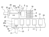
- FIG. 1 is a front view showing a part of the wax model injection molding apparatus of this example and a cross section thereof
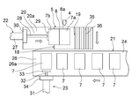
- FIG. 2 is the left side surface of the clamp device in the wax model injection molding apparatus shown in FIG. 1 in which the apparatus main body is omitted.
- FIGS. 3 and 3 are perspective views in which the main body of the wax model injection molding apparatus shown in FIG. 1 and the clamp device are separated, and FIGS. 4 to 9 supply a rubber mold to the clamp portion of the clamp device to provide a filled rubber mold. It is explanatory drawing which shows the process of discharging.
- the wax model injection molding device 1 of this example is composed of a device main body 2 and a clamp device 3 attached to the device main body 2.
- the apparatus main body 2 is provided with a pressure tank for storing wax resin and a vacuum tank (not shown), and the injection nozzle 4 is provided so as to protrude to the outside.
- the apparatus main body 2 configured as described above is known (Patent No. 6059248), and in this example, the known apparatus main body is used.
- the clamp device 3 includes a clamp portion 5 and a support base 6.
- the clamp portion 5 includes a mold 8 having a flat surface portion 8a on which the rubber mold 7 is placed, and a clamp head 9 that can move vertically with respect to the flat surface portion 8a of the mold base 8.
- a support frame 10 is installed on a support base 6, and the clamp head 9 is supported by the support frame 10 so as to be movable in the vertical direction.
- an air-driven cylinder 12 is installed on the upper plate portion 11 of the support frame 10.
- the cylinder rod 13 of the cylinder 12 can be raised and lowered so as to approach and separate from the flat surface portion 8a of the template 8 by driving the cylinder 12.
- a clamp head 9 is attached to the tip of the cylinder rod 13, and by lowering the cylinder rod 13, the rubber mold 7 mounted on the flat surface portion 8a of the mold 8 is pressed and fixed from above by the clamp head 9. It is designed to do.
- the injection port 14 which opens into the rubber mold 7 faces the injection nozzle 4 protruding outward from the apparatus main body 2 and It is positioned and fixed so that it is located on the same axis.
- the clamp portion 5 is supported on the support base 6 so as to be movable back and forth in the direction of the injection nozzle 4 of the apparatus main body 2, and the clamp portion 5 clamping the rubber mold 7 is supported by the ejection nozzle of the apparatus main body 2.
- the injection port 14 opening in the rubber mold 7 and the injection nozzle 4 are fitted and separated from each other.
- a groove-shaped portion 15 is formed on the lower surface of the clamp portion 5, and the upper surface of the support base 6 is slidably slidable on the groove-shaped portion 15.
- a protruding portion 16 to be fitted is formed, and the clamp portion 5 moves along the protruding portion 16, but is not particularly limited.
- an air-driven cylinder is installed in the apparatus main body 2 (not shown), and the tip of the cylinder rod 17 of the cylinder is attached to the clamp portion 5.
- the clamp portion 5 is connected and is moved back and forth in the two directions of the device main body by the cylinder rod 17 that moves forward and backward by the drive of the cylinder, but is not particularly limited.
- the clamp portion 5 is provided with a supply port 18 for supplying the rubber mold 7 into the clamp portion 5 on one side (left side in the drawing in this example) in the left-right direction perpendicular to the front-back movement direction of the support frame 10.
- a discharge port 19 for discharging the filled rubber mold 7a from the inside of the clamp portion 5 is provided on the other side (on the right side in the drawing in this example).
- the sizes of the supply port 18 and the discharge port 19 are not particularly limited as long as they do not interfere with the supply and discharge of the rubber mold 7.
- the transport unit 21 that transports the mold 7 to the front of the standby table 20 and the rubber mold 7 that moves in the left-right direction perpendicular to the movement direction of the clamp unit 5 and stands by on the standby table 20 are transferred from the supply port 18 to the clamp unit 5. It is provided with a rubber mold supply means 22 for supplying to the inside and a rubber mold transfer means 23 for transferring the rubber mold 7 conveyed by the transfer unit 21 to the standby table 20.
- the standby table 20 is connected to the mold table 8 and moves together with the clamp portion 5 as the clamp portion 5 moves.
- the transport unit 21 is composed of a belt conveyor 24, and the transport belt 26 mounted on the gantry 25 is provided so as to be adjacent to the standby stand 20, and the transport surface 26a of the transport belt 26 and the standby stand 20 are provided.
- the positions of the surfaces of the flat surface portion 20a of the above are the same height.
- the transport belt 26 is intermittently rotated by a drive means (not shown) to sequentially transport the rubber mold 7 to the front of the standby table 20.
- the rubber mold supply means 22 is composed of an air-driven cylinder 27 provided with a cylinder rod 28 that advances and retreats in the left-right direction perpendicular to the moving direction of the clamp portion 5. Then, by advancing the cylinder rod 28, the rubber mold 7 waiting on the waiting table 20 by the push plate 29 provided at the tip of the cylinder rod 28 is pushed into the clamp portion 5 from the supply port 18 to be supplied, and the mold table 8 is supplied. It is designed to be positioned at a fixed position on the flat surface portion 8a. The cylinder 27 is fixed to the waiting table 20 by the fixing portion 30.
- the rubber type transfer means 23 is composed of an air-driven cylinder 31 provided with a cylinder rod 32 that moves forward and backward in the same direction as the movement direction of the clamp portion 5. Then, by advancing the cylinder rod 32, the rubber mold 7 which has been conveyed to the front of the standby table 20 by the conveyor belt 26 of the belt conveyor 24 constituting the conveyor 21 by the push plate 33 provided at the tip of the cylinder rod 32. It is extruded and transferred to the waiting table 20.
- the cylinder 31 is fixed to the pedestal 25 of the belt conveyor 24 by the fixing portion 34.
- the discharge port 19 of the clamp portion 5 is provided with a filled rubber mold cradle 35 that is filled with the wax resin in the rubber mold 7 and receives the filled rubber mold 7a discharged from the clamp portion 5.
- the filled rubber mold cradle 35 is composed of a roller conveyor 36, and the roller conveyor 36 is installed so as to incline downward from the discharge port 19, and is discharged from the discharge port 19 to be discharged from the roller conveyor 36.
- the filled rubber mold 7a received above moves on the roller conveyor 36 and is sent to a predetermined place.
- the clamp portion 5 moves forward in the direction of the injection nozzle 4 protruding from the apparatus main body 2 and opens in the rubber mold 7 clamped by the clamp portion 5.
- the next rubber mold 7b conveyed by the conveying unit 21 is waited for. It is designed to be transferred to the table 20.
- the next rubber mold 7b transferred by the rubber mold supply means 22 and waiting on the waiting table 20 is clamped during or after filling the rubber mold 7 with the wax resin.
- the next rubber mold 7b is pushed between the mold 8 and the clamp head 9 of the clamp portion 5.
- the filled rubber mold 7a is pushed out from the inside of the clamp portion 5 and discharged from the discharge port 19 to the filled rubber mold cradle 35, and the next rubber mold 7b is placed at a predetermined position on the mold base 8 of the clamp portion 5. It has become like.
- the rubber mold 7 is pushed between the mold base 8 of the clamp portion 5 and the clamp head 9 by the rubber mold supply means 22, and the standby base 20 does not have the rubber mold 7.
- the cylinder 31 is driven to advance the cylinder rod 32, and the rubber is conveyed to the supply port 18 side by the transfer belt 26 of the belt conveyor 24.
- the first control unit 38 that pushes out the rubber mold 7 and transfers it to the standby table 20, and the second detection unit that detects that the clamp of the filled rubber mold 7a is released after the rubber mold 7 is filled with the wax resin.
- the cylinder 27 In response to the detection signals from 39 and the second detection unit 39, the cylinder 27 is driven to advance the cylinder rod 28, and the next rubber mold 7b waiting on the standby table 20 is transferred from the supply port 18 into the clamp unit 5.
- the filled rubber mold 7a is pushed out from the inside of the clamp portion 5 and discharged from the discharge port 19, and the next rubber mold 7b is discharged from the mold portion 8 of the clamp portion 5.
- the second control unit 40 is provided at a fixed position on the flat surface portion 8a of the above.
- the installation location of the first detection unit 37 and the second detection unit 39 is not limited to this example, and may be installed at any position as long as the detection can be performed.
- the second detection unit 39 of this example detects that the clamp of the filled rubber mold 7a is released by detecting that the cylinder 12 is driven and the cylinder rod 13 is raised.
- the release detection method is not limited to this example, and may be detected by another method.
- the cylinder 27 constituting the rubber mold supply means 22 is driven to retract the cylinder rod 28, and the cylinder 31 constituting the rubber mold transfer means 23 is driven to advance the cylinder rod 32 to advance the transport unit 21.
- the rubber mold 7 transported to the front of the standby table 20 is extruded by the transfer belt 26 constituting the standby table 20 and transferred to the standby table 20 (FIG. 4).
- the cylinder rod 32 of the rubber mold transfer means 23 is retracted, the cylinder rod 28 of the rubber mold supply means 22 is advanced, and the rubber mold 7 waiting on the standby table 20 is moved from the supply port 18 into the clamp portion 5. It is pushed into and supplied to a fixed position on the flat surface portion 8a of the mold 8.
- the transport belt 26 of the transport unit 21 is driven to transport the next rubber mold 7b to the front of the standby table 20 (FIG. 5).
- the rubber mold 7 is clamped by the clamp portion 5, the cylinder rod 28 of the rubber mold supply means 22 is retracted, the clamp portion 5 is advanced toward the two apparatus main bodies in this state, and the rubber mold 7 is attached to the injection nozzle 4.
- the injection port 14 is fitted, and filling of the rubber mold 7 with the wax resin is started (FIG. 6).
- the clamp device 3 moves forward in the direction of the injection nozzle 4, and the injection port 14 and the injection nozzle 4 that open in the rubber mold 7 move forward.
- the cylinder 31 constituting the rubber mold transfer means 23 is driven to advance the cylinder rod 32, and the transfer belt 26 constituting the transfer portion 21 is used.
- the next rubber mold 7b that has been conveyed to the front of the standby table 20 is extruded and transferred to the standby table 20 (FIG. 7).
- the cylinder rod 28 of the rubber mold supply means 22 is advanced, and the next rubber mold 7b waiting on the standby table 20 is pushed into the clamp portion 5 (FIG. 8).
- the rubber mold 7b is pushed in by the force that the clamped rubber mold 7 does not move.
- the filling of the wax resin into the rubber mold 7 is completed, the clamp portion 5 is retracted to separate the injection nozzle 4 and the rubber mold 7, and then the next rubber mold 7b is moved into the clamp portion 5.
- the next rubber mold 7b may be pushed during filling.
- the clamp of the filled rubber mold 7a is released, the cylinder rod 28 of the rubber mold supply means 22 is further advanced, and the filled rubber mold 7a is clamped by the next rubber mold b pushed into the clamp portion 5. It is extruded from the inside of 5 and discharged from the discharge port 19 to the filled rubber mold cradle 35, and the next rubber mold 7b is placed at a predetermined position of the mold base 8 of the clamp portion 5 (FIG. 9).
- the cylinder rod 28 is advanced after the second detection unit 39 detects that the clamp of the filled rubber mold 7a has been released, but the next rubber mold 7b is pushed by the cylinder rod 28.
- the next rubber which is transferred by the rubber mold transfer means 23 and stands by on the waiting table 20 during or after filling the rubber mold 7 with the wax resin.
- the mold 7b is moved into the clamp portion 5 from the supply port 18 provided in the clamp portion 5 by the rubber mold supply means 22, and after the rubber mold 7 is filled with the wax resin, the next rubber mold 7b is transferred to the clamp portion 5. It is pushed between the mold 8 and the clamp head 9, and the filled rubber mold 7a is pushed out from the inside of the clamp portion 5 to be discharged from the discharge port 19 to the filled rubber mold cradle 35, and the next rubber mold 7b is discharged to the clamp portion 5. Can be placed in a predetermined position on the mold 8 of the above.
- the rubber type transfer means 23 provided on the supply port 18 side of the clamp portion 5 is composed of a cylinder 31 provided with a cylinder rod 32 that advances and retreats in the same direction as the movement direction of the clamp portion 5.
- the next rubber mold 7b transported by the transport unit 21 is transferred to the extrusion standby table 20 at the tip of the cylinder rod 32, so that the transport unit has a simple configuration.
- the next rubber mold 7b conveyed by 21 can be reliably transferred to the standby table 20.
- the rubber mold supply means 22 is composed of a cylinder 27 provided with a cylinder rod 28 that advances and retreats in a left-right direction perpendicular to the moving direction of the clamp portion 5, and is formed at the tip of the cylinder rod 28 by advancing the cylinder rod 28. Since the next rubber mold 7b waiting on the waiting table 20 is supplied from the supply port 18 into the clamp portion 5, the next rubber mold 7b waiting on the waiting table 20 has a simple configuration. Can be reliably supplied into the clamp portion 5.
- the first detection unit 37 that detects that the standby table 20 does not have the rubber mold 7 and the rubber mold transfer means 23 that receives the detection signal from the first detection unit 37 are operated by the transfer unit 21.
- the rubber mold supply means 22 is operated to push the next rubber mold 7b between the mold 8 and the clamp head 9 of the clamp unit 5, and the filled rubber is filled.
- a second control unit that pushes the mold 7a out of the clamp portion 5 and discharges it from the discharge port 19 to the filled rubber mold cradle 35, and mounts the next rubber mold 7b at a predetermined position on the mold base 8 of the clamp portion 5. Since the 40 is provided, a series of operations can be automatically and continuously performed from the discharge of the filled rubber mold 7a from the inside of the clamp portion 5 to the supply of the next rubber mold 7b into the clamp portion 5.
Abstract
With a view to achieving a wax model injection molding method and a wax model injection molding apparatus, both of which enable efficient injection molding of a wax model and a shortening of working hours, a wax model injection molding method that comprises a step for clamping a rubber mold and then fitting a fill port of the rubber mold onto an injection nozzle 4, a step for discharging the rubber mold filled with wax resin out of a clamp part 5, and a step for feeding a next rubber mold into the clamp part 5 from which the filled-up rubber mold has been discharged, and a wax model mold injection apparatus for implementing said method, are both configured to be able to perform the two steps, which are the step for discharging the filled-up rubber mold out of the clamp part 5 and the step for feeding a next rubber mold into the clamp part from which the filled-up rubber mold has been discharged, as a single step for, as sequence of operations, moving, after a rubber mold is filled up with wax resin, a next rubber mold into the clamp part 5, pushing out and discharging the filled-up rubber mold out of the clamp part, and feeding a next rubber mold into the clamp part.
Description
本発明は、ロストワックス鋳造に使用されるワックスモデルを成型するワックスモデル射出成型方法およびワックスモデル射出成型装置に関する。
The present invention relates to a wax model injection molding method for molding a wax model used for lost wax casting and a wax model injection molding apparatus.
金属アクセサリなど複雑な形状の鋳造法の一つとしてロストワックス鋳造法が知られている。一般的にロストワックス鋳造法では、製造しようとする原型をシリコンゴム等で被覆し、シリコンゴム等を加硫することによりゴム型を形成し、このゴム型を分割して原型を取り出した後、ゴム型の内部にワックス樹脂を充填してワックスモデルを成型する工程がある。このゴム型の内部にワックス樹脂を充填してワックスモデルを成型する工程が、本発明の対象となる工程である。
The lost wax casting method is known as one of the casting methods for complicated shapes such as metal accessories. Generally, in the lost wax casting method, a prototype to be manufactured is covered with silicon rubber or the like, a rubber mold is formed by vulcanizing the silicon rubber or the like, the rubber mold is divided and the prototype is taken out, and then the prototype is taken out. There is a process of filling the inside of the rubber mold with a wax resin and molding a wax model. The step of filling the inside of the rubber mold with a wax resin and molding the wax model is the step of the present invention.
従来から、ワックスモデルを成型する手段として、ワックス樹脂を射出す射出ノズルを備え、ゴム型へワックス樹脂を充填する装置本体と、ゴム型をクランプし装置本体の射出ノズル方向に前後に移動して、ゴム型に開口する注入口と射出ノズルを嵌合・離反させるクランプ装置が併設されたワックスモデル射出成型装置が知られている(例えば、特許文献1参照。)。
Conventionally, as a means for molding a wax model, an injection nozzle for injecting wax resin is provided, and the device body for filling the rubber mold with wax resin and the device body for clamping the rubber mold and moving back and forth in the direction of the injection nozzle of the device body. , A wax model injection molding device provided with a clamping device for fitting and separating an injection port opening in a rubber mold and an injection nozzle is known (see, for example, Patent Document 1).
このようなワックスモデル射出成型装置にあって、装置本体に併設されたクランプ装置へのゴム型の供給や、クランプ装置からのワックス樹脂を充填した充填済みゴム型の排出にあっては一般に次のように行われている。
In such a wax model injection molding device, the following are generally used for supplying a rubber mold to a clamp device attached to the main body of the device and discharging a filled rubber mold filled with wax resin from the clamp device. It is done like this.
クランプ装置へのゴム型の供給は、ゴム型をクランプ装置のクランプ部内へ、クランプ装置の移動方向に沿って後方から前方へ押し込んで供給し、ゴム型へのワックス樹脂の充填後、ワックス樹脂を充填した充填済みゴム型をクランプ部内から後方に引き抜いてクランプ装置から排出する。そして、充填済みゴム型をクランプ装置から排出した後、次のゴム型をクランプ部内へ押し込んでクランプ装置へ供給する(例えば、特許文献2参照。)。
この動作を繰り返し行いながら連続してワックスモデル射出成型が行われる。 To supply the rubber mold to the clamp device, the rubber mold is pushed into the clamp portion of the clamp device from the rear to the front along the moving direction of the clamp device, and after the rubber mold is filled with the wax resin, the wax resin is supplied. The filled rubber mold is pulled out rearward from the inside of the clamp portion and discharged from the clamp device. Then, after the filled rubber mold is discharged from the clamp device, the next rubber mold is pushed into the clamp portion and supplied to the clamp device (see, for example, Patent Document 2).
Wax model injection molding is continuously performed while repeating this operation.
例えば、金属アクセサリなど、同一形状の製品を大量に製造するロストワックス鋳造にあっては大量のワックスモデルを用意しなければならず、そのためにワックスモデル射出成型の効率化が求められる。
For example, in the case of lost wax casting that mass-produces products of the same shape such as metal accessories, it is necessary to prepare a large amount of wax models, and therefore, efficiency of wax model injection molding is required.
発明者は、ワックスモデル射出成型の効率化を図るべく検討した結果、従来のワックスモデル射出成型装置では、装置本体に併設されたクランプ装置へのゴム型の供給と、クランプ装置からのワックス樹脂を充填した充填済みゴム型の排出は、供給と排出の2つの工程で行っていることに着目し、この2つの工程を1つの工程で行うことによりワックスモデルの成型の効率化を図ることを思いつき、試験研究を重ねた結果、本発明を完成するに到った。
As a result of studying to improve the efficiency of wax model injection molding, the inventor supplies a rubber mold to the clamp device attached to the main body of the conventional wax model injection molding device and uses wax resin from the clamp device. Focusing on the fact that the filled rubber mold is discharged in two processes, supply and discharge, we came up with the idea of improving the efficiency of wax model molding by performing these two processes in one process. As a result of repeated test studies, the present invention has been completed.
本発明の目的は、ワックスモデル射出成型を効率よく行い時間の短縮化を図ることができるワックスモデル射出成型方法およびワックスモデル射出成型装置を提供することにある。
An object of the present invention is to provide a wax model injection molding method and a wax model injection molding apparatus capable of efficiently performing wax model injection molding and shortening the time.
上記の目的を達成するために、請求項1に記載の発明は、中空パターンを内部に有するゴム型をクランプ装置に設けられているクランプ部でクランプして、ゴム型をワックスモデル射出成型装置の装置本体に設けられたワックス樹脂を射出す射出ノズルに嵌合する工程と、ワックス樹脂が充填された充填済みゴム型を前記クランプ部内から排出する工程と、充填済みゴム型を排出した前記クランプ部内に次のゴム型を供給する工程を含むワックスモデル射出成型方法であって、充填済みゴム型を前記クランプ部内から排出する工程と、充填済みゴム型を排出した前記クランプ部内に次のゴム型を供給する工程の2つの工程を、ゴム型へのワックス樹脂の充填後に、次のゴム型を前記クランプ部内へ移動させ、充填済みゴム型を前記クランプ部内から押し出して排出させるとともに、次のゴム型を前記クランプ部内に供給するようにした一連の動作で行う1つの工程とすることを特徴とする。
In order to achieve the above object, the invention according to claim 1 is to clamp a rubber mold having a hollow pattern internally by a clamping portion provided in the clamping device, and to use the rubber mold as a wax model injection molding apparatus. A step of fitting into an injection nozzle for injecting wax resin provided in the main body of the apparatus, a step of discharging a filled rubber mold filled with wax resin from the inside of the clamp portion, and a step of discharging the filled rubber mold in the clamp portion. This is a wax model injection molding method including a step of supplying the next rubber mold to a step of discharging the filled rubber mold from the inside of the clamp portion and a step of ejecting the next rubber mold into the clamp portion from which the filled rubber mold is discharged. In the two steps of supplying, after filling the rubber mold with the wax resin, the next rubber mold is moved into the clamp portion, the filled rubber mold is pushed out from the inside of the clamp portion and discharged, and the next rubber mold is discharged. Is one step performed by a series of operations so as to supply the rubber into the clamp portion.
請求項1に記載のワックスモデル射出成型方法によれば、充填済みゴム型を前記クランプ部内から排出する工程と、充填済みゴム型を排出した前記クランプ部内に次のゴム型を供給する工程の2つの工程を、ゴム型へのワックス樹脂の充填後に、次のゴム型を前記クランプ部へ移動させ、充填済みゴム型を前記クランプ部内から押し出して排出させるとともに、次のゴム型を前記クランプ部内に供給するようにした一連の動作で行う1つの工程とするので、充填済みゴム型の前記クランプ部内からの排出から次のゴム型の前記クランプ部内への供給を効率よく行うことができ、充填済みゴム型の排出から次のゴム型の供給までの時間の短縮化を図ることができる。
According to the wax model injection molding method according to claim 1, there are two steps: a step of discharging the filled rubber mold from the inside of the clamp portion and a step of supplying the next rubber mold into the clamp portion from which the filled rubber mold is discharged. In one step, after filling the rubber mold with the wax resin, the next rubber mold is moved to the clamp portion, the filled rubber mold is pushed out from the inside of the clamp portion and discharged, and the next rubber mold is moved into the clamp portion. Since it is one step performed by a series of operations for supplying, it is possible to efficiently supply the filled rubber mold from the inside of the clamp portion to the next rubber mold in the clamp portion, and the filled rubber mold has been filled. It is possible to shorten the time from the discharge of the rubber mold to the supply of the next rubber mold.
請求項2に記載の発明は、ワックス樹脂を射出す射出ノズルから中空パターンを内部に有するゴム型へワックス樹脂を充填する装置本体に、ゴム型をクランプし前記装置本体の前記射出ノズル方向に前後に移動して、ゴム型に開口する注入口と前記射出ノズルを嵌合・離反させるクランプ装置が併設されたワックスモデル射出成型装置において、前記クランプ装置は、ゴム型を載置する型台とこの型台に対して鉛直方向に移動可能なクランプヘッドからなるクランプ部を備えており、前記クランプ部には、クランプ装置の前後移動方向と直行する左右方向の一側にゴム型を前記クランプ部内に供給する供給口が設けられ、他側にワックス樹脂が充填された充填済みゴム型を前記クランプ部内から排出する排出口が設けられ、前記クランプ部の前記供給口の外側には、前記クランプ部内へ供給するゴム型を待機させる待機台と、ゴム型を前記待機台の手前まで搬送する搬送部と、前記クランプ装置の移動方向と直行する左右方向に移動して前記待機台に待機しているゴム型を前記供給口から前記クランプ部内へ供給するゴム型供給手段と、前記搬送部で搬送されてきたゴム型を前記待機台に移送するゴム型移送手段を備え、前記排出口には、クランプ部内から排出された充填済みゴム型を受ける充填済みゴム型受け台を備えており、前記ゴム型移送手段は、前記クランプ装置が前記射出ノズル方向に前進移動し、ゴム型に開口する前記注入口と前記射出ノズルが嵌合し、前記射出ノズルからゴム型内にワックス樹脂が射出充填される過程で、前記搬送部で搬送されてきた次のゴム型を前記待機台へ移送するようになっており、前記ゴム型供給手段は、ゴム型へのワックス樹脂の充填中または充填後に、前記ゴム型移送手段により移送されて前記待機台に待機している次のゴム型を前記クランプ装置に設けられた前記ゴム型供給口から前記クランプ部内へ移動させ、ゴム型へのワックス樹脂の充填後に、次のゴム型を前記クランプ部の前記型台と前記クランプヘッドの間に押し込み、充填済みゴム型をクランプ部内から押し出して前記排出口から充填済みゴム型受け台へ排出させるとともに、次のゴム型を前記クランプ部の前記型台の所定位置に載置させるようになっていることを特徴とする。
According to the second aspect of the present invention, the rubber mold is clamped to the device main body for filling the rubber mold having a hollow pattern from the injection nozzle for injecting the wax resin to the rubber mold having a hollow pattern inside, and the rubber mold is clamped back and forth in the direction of the injection nozzle of the device main body. In a wax model injection molding device provided with an injection port that opens into a rubber mold and a clamp device that fits and separates the injection nozzle, the clamp device is a mold on which the rubber mold is placed and this. A clamp portion consisting of a clamp head that can move in the vertical direction with respect to the mold base is provided, and the clamp portion has a rubber mold in the clamp portion on one side in the left-right direction perpendicular to the front-back movement direction of the clamping device. A supply port for supplying is provided, a discharge port for discharging the filled rubber mold filled with wax resin from the inside of the clamp portion is provided on the other side, and the outside of the supply port of the clamp portion is inside the clamp portion. A waiting table that makes the rubber mold to be supplied stand by, a transport unit that conveys the rubber mold to the front of the waiting table, and rubber that moves in the left-right direction perpendicular to the moving direction of the clamping device and stands by in the waiting table. A rubber mold supply means for supplying a mold from the supply port to the inside of the clamp portion and a rubber mold transfer means for transferring the rubber mold conveyed by the transport portion to the standby table are provided, and the discharge port is provided with the inside of the clamp portion. The rubber mold transfer means is provided with a filled rubber mold cradle for receiving the filled rubber mold discharged from the rubber mold, and the rubber mold transfer means is provided with the injection port in which the clamping device moves forward in the direction of the injection nozzle and opens in the rubber mold. In the process in which the injection nozzle is fitted and the wax resin is injected and filled into the rubber mold from the injection nozzle, the next rubber mold conveyed by the transfer unit is transferred to the standby table. The rubber mold supply means is provided with the next rubber mold, which is transferred by the rubber mold transfer means and stands by on the standby table, during or after filling the rubber mold with the wax resin. After moving from the rubber mold supply port into the clamp portion and filling the rubber mold with the wax resin, the next rubber mold is pushed between the mold base of the clamp portion and the clamp head to clamp the filled rubber mold. It is characterized in that it is extruded from the inside of the portion and discharged from the discharge port to the filled rubber mold cradle, and the next rubber mold is placed at a predetermined position on the mold base of the clamp portion.
請求項2に記載のワックスモデル射出成型装置によれば、ゴム型へのワックス樹脂の充填中または充填後に、前記ゴム型移送手段により移送され前記待機台に待機している次のゴム型を、前記ゴム型供給手段により前記クランプ部に設けられた前記供給口から前記クランプ部内へ移動させ、ゴム型へのワックス樹脂の充填後に、次のゴム型を前記クランプ部の前記型台と前記クランプヘッドの間に押し込み、充填済みゴム型をクランプ部内から押し出して前記排出口から充填済みゴム型受け台へ排出させるとともに、次のゴム型を前記クランプ部の前記型台の所定位置に載置させることができる。
これにより、充填済みゴム型の前記クランプ部内からの排出から次のゴム型の前記クランプ部内への供給を一連の動作で効率よく行うことができ、充填済みゴム型の排出から次のゴム型の供給までの時間の短縮化を図ることができる。 According to the wax model injection molding apparatus according toclaim 2, the next rubber mold transferred by the rubber mold transfer means and waiting on the waiting table during or after filling the rubber mold with the wax resin is provided. After the rubber mold is moved into the clamp portion from the supply port provided in the clamp portion by the rubber mold supply means and the rubber mold is filled with the wax resin, the next rubber mold is transferred to the mold base of the clamp portion and the clamp head. The filled rubber mold is pushed out from the inside of the clamp portion to be discharged from the discharge port to the filled rubber mold cradle, and the next rubber mold is placed in a predetermined position on the mold base of the clamp portion. Can be done.
As a result, it is possible to efficiently supply the filled rubber mold from the inside of the clamp portion to the next rubber mold into the clamp portion by a series of operations, and from the discharge of the filled rubber mold to the next rubber mold. The time to supply can be shortened.
これにより、充填済みゴム型の前記クランプ部内からの排出から次のゴム型の前記クランプ部内への供給を一連の動作で効率よく行うことができ、充填済みゴム型の排出から次のゴム型の供給までの時間の短縮化を図ることができる。 According to the wax model injection molding apparatus according to
As a result, it is possible to efficiently supply the filled rubber mold from the inside of the clamp portion to the next rubber mold into the clamp portion by a series of operations, and from the discharge of the filled rubber mold to the next rubber mold. The time to supply can be shortened.
請求項3に記載の発明は、請求項2に記載のワックスモデル射出成型装置において、前記クランプ装置の前記供給口側に備えられた前記ゴム型移送手段は、前記クランプ装置の移動方向と同方向に進退するシリンダーロッドを備えたシリンダーで構成されており、前記シリンダーロッドの前進により、前記シリンダーロッドの先端で、前記搬送部で搬送されてきた次のゴム型を押出し前記待機台へ移送させるようになっており、また、前記ゴム型供給手段は、前記クランプ装置の移動方向と直行する左右方向に進退するシリンダーロッドを備えたシリンダーで構成されており、前記シリンダーロッドの前進により、前記シリンダーロッドの先端で前記待機台に待機している次のゴム型を前記供給口から前記クランプ部内へ供給するようになっていることを特徴とする。
The invention according to claim 3 is the wax model injection molding apparatus according to claim 2, wherein the rubber mold transfer means provided on the supply port side of the clamp device is in the same direction as the moving direction of the clamp device. It is composed of a cylinder equipped with a cylinder rod that moves forward and backward, and by advancing the cylinder rod, the next rubber mold transported by the transport unit is extruded and transferred to the standby table at the tip of the cylinder rod. Further, the rubber mold supply means is composed of a cylinder provided with a cylinder rod that advances and retreats in a left-right direction perpendicular to the moving direction of the clamping device, and the cylinder rod is moved forward by the advancement of the cylinder rod. The next rubber mold waiting on the standby table at the tip of the cylinder is supplied from the supply port into the clamp portion.
請求項3に記載のワックスモデル射出成型装置によれば、前記クランプ装置の前記供給口側に備えられた前記ゴム型移送手段は、前記クランプ装置の移動方向と同方向に進退するシリンダーロッドを備えたシリンダーで構成されており、前記シリンダーロッドの前進により、前記シリンダーロッドの先端で、前記搬送部で搬送されてきた次のゴム型を押出し前記待機台へ移送させるようになっているので、簡単な構成で、前記搬送部で搬送されてきた次のゴム型を前記待機台へ確実に移送させることができる。
また、前記ゴム型供給手段は、前記クランプ装置の移動方向と直行する左右方向に進退するシリンダーロッドを備えたシリンダーで構成されており、前記シリンダーロッドの前進により、前記シリンダーロッドの先端で前記待機台に待機している次のゴム型を前記供給口から前記クランプ部内へ供給するようになっているので、簡単な構成で、前記待機台に待機している次のゴム型を前記クランプ部内へ確実に供給することができる。 According to the wax model injection molding apparatus according toclaim 3, the rubber mold transfer means provided on the supply port side of the clamp device includes a cylinder rod that advances and retreats in the same direction as the movement direction of the clamp device. It is easy because it is composed of a cylinder, and by advancing the cylinder rod, the next rubber mold transported by the transport unit is extruded and transferred to the standby table at the tip of the cylinder rod. With such a configuration, the next rubber mold conveyed by the transfer unit can be reliably transferred to the standby table.
Further, the rubber mold supply means is composed of a cylinder provided with a cylinder rod that advances and retreats in a left-right direction perpendicular to the moving direction of the clamp device, and the advance of the cylinder rod causes the standby at the tip of the cylinder rod. Since the next rubber mold waiting on the table is supplied from the supply port into the clamp portion, the next rubber mold waiting on the standby table can be supplied into the clamp portion with a simple configuration. It can be reliably supplied.
また、前記ゴム型供給手段は、前記クランプ装置の移動方向と直行する左右方向に進退するシリンダーロッドを備えたシリンダーで構成されており、前記シリンダーロッドの前進により、前記シリンダーロッドの先端で前記待機台に待機している次のゴム型を前記供給口から前記クランプ部内へ供給するようになっているので、簡単な構成で、前記待機台に待機している次のゴム型を前記クランプ部内へ確実に供給することができる。 According to the wax model injection molding apparatus according to
Further, the rubber mold supply means is composed of a cylinder provided with a cylinder rod that advances and retreats in a left-right direction perpendicular to the moving direction of the clamp device, and the advance of the cylinder rod causes the standby at the tip of the cylinder rod. Since the next rubber mold waiting on the table is supplied from the supply port into the clamp portion, the next rubber mold waiting on the standby table can be supplied into the clamp portion with a simple configuration. It can be reliably supplied.
請求項4に記載の発明は、請求項2または3に記載のワックスモデル射出成型装置において、前記ゴム型供給手段によりゴム型が前記クランプ部の前記型台と前記クランプヘッドの間に押しこまれ、前記待機台にゴム型が無いことを検知する第1検知部と、前記第1検知部からの検知信号を受け、前記ゴム型移送手段を作動させて前記搬送部で搬送されてきた次のゴム型を前記待機台へ移送させる第1制御部と、ゴム型へのワックス樹脂の充填後、ゴム型のクランプを解除したことを検知する第2検知部と、第2検知部からの検知信号を受け、前記ゴム型供給手段を作動させて次のゴム型を前記クランプ部の前記型台と前記クランプヘッドの間に押し込み、充填済みゴム型をクランプ部内から押し出して前記ゴム型排出口から充填済みゴム型受け台へ排出させるとともに、次のゴム型を前記クランプ部の前記型台の所定位置に載置させる第2制御部を備えていることを特徴とする。
According to the fourth aspect of the present invention, in the wax model injection molding apparatus according to the second or third aspect, the rubber mold is pushed between the mold base of the clamp portion and the clamp head by the rubber mold supply means. The next detection unit that detects that there is no rubber mold on the standby table and receives the detection signal from the first detection unit and operates the rubber mold transfer means to be transported by the transfer unit. Detection signals from the first control unit that transfers the rubber mold to the standby table, the second detection unit that detects that the rubber mold has been released after filling the rubber mold with wax resin, and the second detection unit. Then, the rubber mold supply means is operated to push the next rubber mold between the mold base of the clamp portion and the clamp head, and the filled rubber mold is pushed out from the inside of the clamp portion and filled from the rubber mold discharge port. It is characterized by having a second control unit for discharging the rubber mold to the finished rubber mold cradle and mounting the next rubber mold at a predetermined position on the mold base of the clamp portion.
請求項4に記載のワックスモデル射出成型装置によれば、充填済みゴム型の前記クランプ部内からの排出から次のゴム型の前記クランプ部内への供給を一連の動作を自動的に連続して行うことができる。
According to the wax model injection molding apparatus according to claim 4, a series of operations is automatically and continuously performed from the discharge of the filled rubber mold from the inside of the clamp portion to the supply of the next rubber mold into the clamp portion. be able to.
以上のように、本発明に係るワックスモデル射出成型方法およびワックスモデル射出成型装置によれば、充填済みゴム型の前記クランプ部内からの排出から次のゴム型の前記クランプ部内への供給を効率よく行うことができ、充填済みゴム型の排出から次のゴム型の供給までの時間の短縮化を図ることができ、これによりワックスモデル射出成型のコストダウンを図ることができる。
As described above, according to the wax model injection molding method and the wax model injection molding apparatus according to the present invention, the filled rubber mold is efficiently supplied from the discharge from the inside of the clamp portion to the next rubber mold into the clamp portion. This can be done, and the time from the discharge of the filled rubber mold to the supply of the next rubber mold can be shortened, which can reduce the cost of the wax model injection molding.
以下、本発明に係るワックスモデル射出成型方法およびワックスモデル射出成型装置の実施の形態を説明する。
Hereinafter, embodiments of the wax model injection molding method and the wax model injection molding apparatus according to the present invention will be described.
先ず、ワックスモデル射出成型方法の実施の形態の一例を説明する。
本発明に係るワックスモデル射出成型方法は、中空パターンを内部に有するゴム型をクランプ装置に設けられているクランプ部でクランプして、ゴム型をワックスモデル射出成型装置の装置本体に設けられたワックス樹脂を射出す射出ノズルに嵌合する工程と、ワックス樹脂が充填された充填済みゴム型を前記クランプ部内から排出する工程と、充填済みゴム型を排出した前記クランプ部内に次のゴム型を供給する工程を含んでいる。 First, an example of an embodiment of the wax model injection molding method will be described.
In the wax model injection molding method according to the present invention, the rubber mold having a hollow pattern inside is clamped by the clamp portion provided in the clamping device, and the rubber mold is clamped by the wax provided in the device main body of the wax model injection molding device. A step of fitting into an injection nozzle for injecting resin, a step of discharging a filled rubber mold filled with wax resin from the inside of the clamp portion, and a step of supplying the next rubber mold into the clamp portion from which the filled rubber mold is discharged. Includes the process of doing.
本例では、前記した充填済みゴム型を前記クランプ部内から排出する工程と、充填済みゴム型を排出した前記クランプ部内に次のゴム型を供給する工程の2つの工程を、ゴム型へのワックス樹脂の充填後に、次のゴム型をクランプ部内へ移動させ、充填済みゴム型をクランプ部内から押し出して排出させるとともに、次のゴム型をクランプ部内に供給するようにした一連の動作で行う1つの工程とする。
In this example, two steps, a step of discharging the filled rubber mold from the inside of the clamp portion and a step of supplying the next rubber mold into the clamp portion from which the filled rubber mold is discharged, are performed by waxing the rubber mold. After filling the resin, the next rubber mold is moved into the clamp part, the filled rubber mold is pushed out from the inside of the clamp part and discharged, and the next rubber mold is supplied into the clamp part. It is a process.
以上のように、本発明のワックスモデル射出成型方法によれば、充填済みゴム型をクランプ部内から排出する工程と、充填済みゴム型を排出したクランプ部内に次のゴム型を供給する工程の2つの工程を、ゴム型へのワックス樹脂の充填後に、次のゴム型をクランプ部内へ移動させ、充填済みゴム型をクランプ部内から押し出して排出させるとともに、次のゴム型をクランプ部内に供給するようにした一連の動作で行う1つの工程とするので、充填済みゴム型のクランプ部内からの排出から次のゴム型のクランプ部内への供給を効率よく行うことができ、充填済みゴム型の排出から次のゴム型の供給までの時間の短縮化を図ることができる。
As described above, according to the wax model injection molding method of the present invention, there are two steps: a step of discharging the filled rubber mold from the inside of the clamp portion and a step of supplying the next rubber mold into the clamp portion from which the filled rubber mold is discharged. In one step, after filling the rubber mold with the wax resin, the next rubber mold is moved into the clamp part, the filled rubber mold is pushed out from the inside of the clamp part and discharged, and the next rubber mold is supplied into the clamp part. Since it is one step performed by a series of operations, it is possible to efficiently supply the filled rubber mold from the inside of the clamp part to the next rubber mold clamp part, and from the discharge of the filled rubber mold. It is possible to shorten the time until the next rubber mold is supplied.
次に、前記のワックスモデル射出成型方法を実施するワックスモデル射出成型装置の実施の形態の一例を図1~図9により説明する。
図1は本例のワックスモデル射出成型装置を示す一部を省略し、一部を断面した正面図、図2は図1に示すワックスモデル射出成型装置における装置本体を省略したクランプ装置の左側面図、図3は図1に示すワックスモデル射出成型装置における装置本体とクランプ装置とを分離した斜視図、図4~図9はクランプ装置のクランプ部へゴム型を供給し、充填済みゴム型を排出する工程を示す説明図である。 Next, an example of the embodiment of the wax model injection molding apparatus that implements the wax model injection molding method will be described with reference to FIGS. 1 to 9.
FIG. 1 is a front view showing a part of the wax model injection molding apparatus of this example and a cross section thereof, and FIG. 2 is the left side surface of the clamp device in the wax model injection molding apparatus shown in FIG. 1 in which the apparatus main body is omitted. FIGS. 3 and 3 are perspective views in which the main body of the wax model injection molding apparatus shown in FIG. 1 and the clamp device are separated, and FIGS. 4 to 9 supply a rubber mold to the clamp portion of the clamp device to provide a filled rubber mold. It is explanatory drawing which shows the process of discharging.
本例のワックスモデル射出成型装置1は、装置本体2と、装置本体2に併設されたクランプ装置3とで構成されている。
The wax model injection molding device 1 of this example is composed of a device main body 2 and a clamp device 3 attached to the device main body 2.
装置本体2は、内部にワックス樹脂を貯蔵する加圧タンクと、真空タンクとを備えており(図示せず)、外部に射出ノズル4が突出するように設けられている。このように構成される装置本体2は公知であり、(特許第6059248号)、本例では公知の装置本体を使用している。
The apparatus main body 2 is provided with a pressure tank for storing wax resin and a vacuum tank (not shown), and the injection nozzle 4 is provided so as to protrude to the outside. The apparatus main body 2 configured as described above is known (Patent No. 6059248), and in this example, the known apparatus main body is used.
クランプ装置3は、クランプ部5と支持台6を備えている。クランプ部5は、ゴム型7を載置するための平面部8aを有する型台8と、この型台8の平面部8aに対して鉛直方向に移動可能なクランプヘッド9を備えている。クランプヘッド9は、支持台6上に支持枠10が設置されており、支持枠10にクランプヘッド9が鉛直方向に移動可能に支持されている。支持枠10の上板部11には、例えば空気駆動のシリンダー12が設置されている。シリンダー12のシリンダーロッド13は、シリンダー12の駆動により型台8の平面部8aに接近・離間するように昇降可能となっている。シリンダーロッド13の先端にはクランプヘッド9が取り付けられており、シリンダーロッド13を下降させることにより、クランプヘッド9で型台8の平面部8aに載置されているゴム型7を上方から押さえつけ固定するようになっている。
The clamp device 3 includes a clamp portion 5 and a support base 6. The clamp portion 5 includes a mold 8 having a flat surface portion 8a on which the rubber mold 7 is placed, and a clamp head 9 that can move vertically with respect to the flat surface portion 8a of the mold base 8. In the clamp head 9, a support frame 10 is installed on a support base 6, and the clamp head 9 is supported by the support frame 10 so as to be movable in the vertical direction. For example, an air-driven cylinder 12 is installed on the upper plate portion 11 of the support frame 10. The cylinder rod 13 of the cylinder 12 can be raised and lowered so as to approach and separate from the flat surface portion 8a of the template 8 by driving the cylinder 12. A clamp head 9 is attached to the tip of the cylinder rod 13, and by lowering the cylinder rod 13, the rubber mold 7 mounted on the flat surface portion 8a of the mold 8 is pressed and fixed from above by the clamp head 9. It is designed to do.
型台8の平面部8aに載置されクランプヘッド9で固定されるゴム型7は、ゴム型7に開口する注入口14が、装置本体2から外部に突出する射出ノズル4に対向し、且つ同一軸線上に位置するように位置決めされて固定される。
In the rubber mold 7 which is placed on the flat surface portion 8a of the mold base 8 and fixed by the clamp head 9, the injection port 14 which opens into the rubber mold 7 faces the injection nozzle 4 protruding outward from the apparatus main body 2 and It is positioned and fixed so that it is located on the same axis.
また、本例では、クランプ部5は、支持台6に装置本体2の射出ノズル4方向に前後に移動可能に支持されており、ゴム型7をクランプしたクランプ部5を装置本体2の射出ノズル4方向に前後に移動させることにより、ゴム型7に開口する注入口14と射出ノズル4が嵌合・離反するようになっている。
Further, in this example, the clamp portion 5 is supported on the support base 6 so as to be movable back and forth in the direction of the injection nozzle 4 of the apparatus main body 2, and the clamp portion 5 clamping the rubber mold 7 is supported by the ejection nozzle of the apparatus main body 2. By moving it back and forth in four directions, the injection port 14 opening in the rubber mold 7 and the injection nozzle 4 are fitted and separated from each other.
クランプ部5を支持台6に移動可能に支持する手段として、本例では、クランプ部5の下面に溝状部15が形成され、支持台6の上面には溝状部15に摺動自在に嵌合する突状部16が形成されており、突状部16に沿ってクランプ部5が移動するようになっているが、特に限定されない。
As a means for movably supporting the clamp portion 5 on the support base 6, in this example, a groove-shaped portion 15 is formed on the lower surface of the clamp portion 5, and the upper surface of the support base 6 is slidably slidable on the groove-shaped portion 15. A protruding portion 16 to be fitted is formed, and the clamp portion 5 moves along the protruding portion 16, but is not particularly limited.
また、クランプ部5を移動させる手段として、本例では、装置本体2内に、例えば空気駆動のシリンダーが設置されており(図示せず。)、シリンダーのシリンダーロッド17の先端がクランプ部5に接続されており、シリンダーの駆動で進退するシリンダーロッド17によりクランプ部5が装置本体2方向に前後に移動するようになっているが、特に限定されない。
Further, as a means for moving the clamp portion 5, in this example, for example, an air-driven cylinder is installed in the apparatus main body 2 (not shown), and the tip of the cylinder rod 17 of the cylinder is attached to the clamp portion 5. The clamp portion 5 is connected and is moved back and forth in the two directions of the device main body by the cylinder rod 17 that moves forward and backward by the drive of the cylinder, but is not particularly limited.
また、クランプ部5には、支持枠10における前後移動方向と直行する左右方向の一側(本例では図上左側)にゴム型7をクランプ部5内に供給する供給口18が設けられ、他側(本例では図上右側)に充填済みゴム型7aをクランプ部5内から排出する排出口19が設けられている。供給口18および排出口19の大きさは、ゴム型7の供給や排出の妨げにならない限り特に限定されない。
Further, the clamp portion 5 is provided with a supply port 18 for supplying the rubber mold 7 into the clamp portion 5 on one side (left side in the drawing in this example) in the left-right direction perpendicular to the front-back movement direction of the support frame 10. A discharge port 19 for discharging the filled rubber mold 7a from the inside of the clamp portion 5 is provided on the other side (on the right side in the drawing in this example). The sizes of the supply port 18 and the discharge port 19 are not particularly limited as long as they do not interfere with the supply and discharge of the rubber mold 7.
クランプ部5の供給口18側には、型台8の平面部8aと面の位置を同じくする平面部20aを有し、クランプ部5へ供給するゴム型7を待機させる待機台20と、ゴム型7を待機台20の手前まで搬送する搬送部21と、クランプ部5の移動方向と直行する左右方向に移動して待機台20に待機しているゴム型7を供給口18からクランプ部5内へ供給するゴム型供給手段22と、搬送部21で搬送されてきたゴム型7を待機台20に移送するゴム型移送手段23とを備えている。
On the supply port 18 side of the clamp portion 5, there is a flat surface portion 20a having the same surface position as the flat surface portion 8a of the mold base 8, and a standby base 20 for holding the rubber mold 7 to be supplied to the clamp portion 5 and rubber. The transport unit 21 that transports the mold 7 to the front of the standby table 20 and the rubber mold 7 that moves in the left-right direction perpendicular to the movement direction of the clamp unit 5 and stands by on the standby table 20 are transferred from the supply port 18 to the clamp unit 5. It is provided with a rubber mold supply means 22 for supplying to the inside and a rubber mold transfer means 23 for transferring the rubber mold 7 conveyed by the transfer unit 21 to the standby table 20.
待機台20は型台8に繋がっており、クランプ部5と一体となってクランプ部5の移動に伴って移動する。搬送部21は、本例では、ベルトコンベアー24で構成され、架台25に架けられた搬送ベルト26が待機台20に隣接するように設けられており、搬送ベルト26の搬送面26aと待機台20の平面部20aの面の位置が同じ高さとなっている。そして、搬送ベルト26は駆動手段(図示しない。)により間欠的に回転し、ゴム型7を順次待機台20の手前までへ搬送するようになっている。
The standby table 20 is connected to the mold table 8 and moves together with the clamp portion 5 as the clamp portion 5 moves. In this example, the transport unit 21 is composed of a belt conveyor 24, and the transport belt 26 mounted on the gantry 25 is provided so as to be adjacent to the standby stand 20, and the transport surface 26a of the transport belt 26 and the standby stand 20 are provided. The positions of the surfaces of the flat surface portion 20a of the above are the same height. The transport belt 26 is intermittently rotated by a drive means (not shown) to sequentially transport the rubber mold 7 to the front of the standby table 20.
ゴム型供給手段22は、本例では、クランプ部5の移動方向と直行する左右方向に進退するシリンダーロッド28を備えた空気駆動のシリンダー27で構成されている。そして、シリンダーロッド28の前進により、シリンダーロッド28の先端に設けた押板29で待機台20に待機しているゴム型7を供給口18からクランプ部5内へ押し込み供給し、型台8の平面部8aにおける固定位置に位置させるようになっている。シリンダー27は、固定部30により待機台20に固定されている。
In this example, the rubber mold supply means 22 is composed of an air-driven cylinder 27 provided with a cylinder rod 28 that advances and retreats in the left-right direction perpendicular to the moving direction of the clamp portion 5. Then, by advancing the cylinder rod 28, the rubber mold 7 waiting on the waiting table 20 by the push plate 29 provided at the tip of the cylinder rod 28 is pushed into the clamp portion 5 from the supply port 18 to be supplied, and the mold table 8 is supplied. It is designed to be positioned at a fixed position on the flat surface portion 8a. The cylinder 27 is fixed to the waiting table 20 by the fixing portion 30.
ゴム型移送手段23は、本例では、クランプ部5の移動方向と同方向に進退するシリンダーロッド32を備えた空気駆動のシリンダー31で構成されている。そして、シリンダーロッド32の前進により、シリンダーロッド32の先端に設けた押板33で、搬送部21を構成するベルトコンベアー24の搬送ベルト26で待機台20の手前まで搬送されてきたゴム型7を押出し、待機台20へ移送させるようになっている。シリンダー31は、固定部34によりベルトコンベアー24の架台25に固定されている。
In this example, the rubber type transfer means 23 is composed of an air-driven cylinder 31 provided with a cylinder rod 32 that moves forward and backward in the same direction as the movement direction of the clamp portion 5. Then, by advancing the cylinder rod 32, the rubber mold 7 which has been conveyed to the front of the standby table 20 by the conveyor belt 26 of the belt conveyor 24 constituting the conveyor 21 by the push plate 33 provided at the tip of the cylinder rod 32. It is extruded and transferred to the waiting table 20. The cylinder 31 is fixed to the pedestal 25 of the belt conveyor 24 by the fixing portion 34.
また、クランプ部5の排出口19には、ゴム型7にワックス樹脂が充填されクランプ部5から排出された充填済みゴム型7aを受ける充填済みゴム型受け台35を備えている。本例では、充填済みゴム型受け台35はローラーコンベアー36で構成されており、ローラーコンベアー36は排出口19から下方に傾斜するように設置されており、排出口19から排出され、ローラーコンベアー36上に受けられた充填済みゴム型7aは、ローラーコンベアー36上を移動して所定の場所に送られる。
Further, the discharge port 19 of the clamp portion 5 is provided with a filled rubber mold cradle 35 that is filled with the wax resin in the rubber mold 7 and receives the filled rubber mold 7a discharged from the clamp portion 5. In this example, the filled rubber mold cradle 35 is composed of a roller conveyor 36, and the roller conveyor 36 is installed so as to incline downward from the discharge port 19, and is discharged from the discharge port 19 to be discharged from the roller conveyor 36. The filled rubber mold 7a received above moves on the roller conveyor 36 and is sent to a predetermined place.
前記のように構成されたゴム型移送手段23にあっては、クランプ部5が装置本体2から突出する射出ノズル4方向に前進移動し、クランプ部5でクランプされているゴム型7に開口する注入口14と射出ノズル4が嵌合し、射出ノズル4からゴム型7内にワックス樹脂が射出充填される過程で、あるいは充填後、搬送部21で搬送されてきた次のゴム型7bを待機台20へ移送するようになっている。
In the rubber mold transfer means 23 configured as described above, the clamp portion 5 moves forward in the direction of the injection nozzle 4 protruding from the apparatus main body 2 and opens in the rubber mold 7 clamped by the clamp portion 5. In the process where the injection port 14 and the injection nozzle 4 are fitted and the wax resin is injected and filled into the rubber mold 7 from the injection nozzle 4, or after filling, the next rubber mold 7b conveyed by the conveying unit 21 is waited for. It is designed to be transferred to the table 20.
また、ゴム型供給手段22にあっては、ゴム型7へのワックス樹脂の充填中または充填後に、ゴム型供給手段22により移送されて待機台20に待機している次のゴム型7bをクランプ部5に設けられた供給口18からクランプ部5内へ移動させ、ゴム型7へのワックス樹脂の充填後に、次のゴム型7bをクランプ部5の型台8とクランプヘッド9の間に押し込み、充填済みゴム型7aをクランプ部5内から押し出して排出口19から充填済みゴム型受け台35へ排出させるとともに、次のゴム型7bをクランプ部5の型台8の所定位置に載置させるようになっている。
Further, in the rubber mold supply means 22, the next rubber mold 7b transferred by the rubber mold supply means 22 and waiting on the waiting table 20 is clamped during or after filling the rubber mold 7 with the wax resin. After moving from the supply port 18 provided in the portion 5 into the clamp portion 5 and filling the rubber mold 7 with the wax resin, the next rubber mold 7b is pushed between the mold 8 and the clamp head 9 of the clamp portion 5. , The filled rubber mold 7a is pushed out from the inside of the clamp portion 5 and discharged from the discharge port 19 to the filled rubber mold cradle 35, and the next rubber mold 7b is placed at a predetermined position on the mold base 8 of the clamp portion 5. It has become like.
また、本例では、クランプ装置3は、ゴム型供給手段22によりゴム型7がクランプ部5の型台8とクランプヘッド9の間に押しこまれ、待機台20にゴム型7が無いことを検知する第1検知部37と、第1検知部37からの検知信号を受け、シリンダー31を駆動してシリンダーロッド32を前進させ、ベルトコンベアー24の搬送ベルト26で供給口18側へ搬送されてきたゴム型7を押出して待機台20へ移送させる第1制御部38と、ゴム型7へのワックス樹脂の充填後、充填済みゴム型7aのクランプが解除されたことを検知する第2検知部39と、第2検知部39からの検知信号を受け、シリンダー27を駆動してシリンダーロッド28を前進させ、待機台20に待機している次のゴム型7bを供給口18からクランプ部5内へ供給して型台8とクランプヘッド9の間に押し込み、充填済みゴム型7aをクランプ部5内から押し出して排出口19から排出させるとともに、次のゴム型7bをクランプ部5の型台8の平面部8aにおける固定位置に位置させる第2制御部40を備えている。
なお、第1検知部37及び第2検知部39の設置箇所は本例に限られず、検知を行うことができる箇所であればいずれの位置に設置してもよい。
また、本例の第2検知部39はシリンダー12が駆動してシリンダーロッド13が上昇したことを検出することにより充填済みゴム型7aのクランプが解除されたことを検知しているが、クランプの解除の検知方法は本例に限られず、他の方法によって検知してもよい。 Further, in this example, in theclamp device 3, the rubber mold 7 is pushed between the mold base 8 of the clamp portion 5 and the clamp head 9 by the rubber mold supply means 22, and the standby base 20 does not have the rubber mold 7. Upon receiving the detection signals from the first detection unit 37 to detect and the first detection unit 37, the cylinder 31 is driven to advance the cylinder rod 32, and the rubber is conveyed to the supply port 18 side by the transfer belt 26 of the belt conveyor 24. The first control unit 38 that pushes out the rubber mold 7 and transfers it to the standby table 20, and the second detection unit that detects that the clamp of the filled rubber mold 7a is released after the rubber mold 7 is filled with the wax resin. In response to the detection signals from 39 and the second detection unit 39, the cylinder 27 is driven to advance the cylinder rod 28, and the next rubber mold 7b waiting on the standby table 20 is transferred from the supply port 18 into the clamp unit 5. The filled rubber mold 7a is pushed out from the inside of the clamp portion 5 and discharged from the discharge port 19, and the next rubber mold 7b is discharged from the mold portion 8 of the clamp portion 5. The second control unit 40 is provided at a fixed position on the flat surface portion 8a of the above.
The installation location of thefirst detection unit 37 and the second detection unit 39 is not limited to this example, and may be installed at any position as long as the detection can be performed.
Further, thesecond detection unit 39 of this example detects that the clamp of the filled rubber mold 7a is released by detecting that the cylinder 12 is driven and the cylinder rod 13 is raised. The release detection method is not limited to this example, and may be detected by another method.
なお、第1検知部37及び第2検知部39の設置箇所は本例に限られず、検知を行うことができる箇所であればいずれの位置に設置してもよい。
また、本例の第2検知部39はシリンダー12が駆動してシリンダーロッド13が上昇したことを検出することにより充填済みゴム型7aのクランプが解除されたことを検知しているが、クランプの解除の検知方法は本例に限られず、他の方法によって検知してもよい。 Further, in this example, in the
The installation location of the
Further, the
次に、クランプ装置2のクランプ部5へゴム型7の供給から充填済みゴム型7aを排出するまでの工程を図4~図9により説明する。
Next, the process from the supply of the rubber mold 7 to the clamp portion 5 of the clamp device 2 to the discharge of the filled rubber mold 7a will be described with reference to FIGS. 4 to 9.
先ず、ゴム型供給手段22を構成するシリンダー27を駆動し、シリンダーロッド28を後退させた状態とし、ゴム型移送手段23を構成するシリンダー31を駆動してシリンダーロッド32を前進させ、搬送部21を構成する搬送ベルト26により待機台20の手前まで搬送されてきたゴム型7を押出し、待機台20へ移送させる(図4)。
First, the cylinder 27 constituting the rubber mold supply means 22 is driven to retract the cylinder rod 28, and the cylinder 31 constituting the rubber mold transfer means 23 is driven to advance the cylinder rod 32 to advance the transport unit 21. The rubber mold 7 transported to the front of the standby table 20 is extruded by the transfer belt 26 constituting the standby table 20 and transferred to the standby table 20 (FIG. 4).
次に、ゴム型移送手段23のシリンダーロッド32を後退させ、ゴム型供給手段22のシリンダーロッド28を前進させて、待機台20に待機しているゴム型7を供給口18からクランプ部5内へ押し込み供給し、型台8の平面部8aにおける固定位置に位置させる。
この過程で、搬送部21の搬送ベルト26を駆動して次のゴム型7bを待機台20の手前まで搬送する(図5)。 Next, thecylinder rod 32 of the rubber mold transfer means 23 is retracted, the cylinder rod 28 of the rubber mold supply means 22 is advanced, and the rubber mold 7 waiting on the standby table 20 is moved from the supply port 18 into the clamp portion 5. It is pushed into and supplied to a fixed position on the flat surface portion 8a of the mold 8.
In this process, thetransport belt 26 of the transport unit 21 is driven to transport the next rubber mold 7b to the front of the standby table 20 (FIG. 5).
この過程で、搬送部21の搬送ベルト26を駆動して次のゴム型7bを待機台20の手前まで搬送する(図5)。 Next, the
In this process, the
次に、クランプ部5でゴム型7をクランプし、ゴム型供給手段22のシリンダーロッド28を後退させ、この状態でクランプ部5を装置本2体側に前進させ、射出ノズル4にゴム型7の注入口14を嵌合し、ゴム型7内へのワックス樹脂の充填を開始する(図6)。
Next, the rubber mold 7 is clamped by the clamp portion 5, the cylinder rod 28 of the rubber mold supply means 22 is retracted, the clamp portion 5 is advanced toward the two apparatus main bodies in this state, and the rubber mold 7 is attached to the injection nozzle 4. The injection port 14 is fitted, and filling of the rubber mold 7 with the wax resin is started (FIG. 6).
次に、第1検知部37により待機台20にゴム型7が無いことを検知したら、クランプ装置3が射出ノズル4方向に前進移動し、ゴム型7に開口する注入口14と射出ノズル4が嵌合し、ゴム型7内にワックス樹脂が射出充填される過程で、ゴム型移送手段23を構成するシリンダー31を駆動してシリンダーロッド32を前進させ、搬送部21を構成する搬送ベルト26により待機台20の手前まで搬送されてきた次のゴム型7bを押出し、待機台20へ移送させる(図7)。
Next, when the first detection unit 37 detects that the standby table 20 does not have the rubber mold 7, the clamp device 3 moves forward in the direction of the injection nozzle 4, and the injection port 14 and the injection nozzle 4 that open in the rubber mold 7 move forward. In the process of fitting and injecting and filling the rubber mold 7 with the wax resin, the cylinder 31 constituting the rubber mold transfer means 23 is driven to advance the cylinder rod 32, and the transfer belt 26 constituting the transfer portion 21 is used. The next rubber mold 7b that has been conveyed to the front of the standby table 20 is extruded and transferred to the standby table 20 (FIG. 7).
次に、ゴム型供給手段22のシリンダーロッド28を前進させて、待機台20に待機している次のゴム型7bをクランプ部5内へ押し込む(図8)。ゴム型7bの押し込みはクランプされているゴム型7が動かない力で行う。なお、本例では、ゴム型7内へのワックス樹脂の充填が完了し、クランプ部5を後退させて射出ノズル4とゴム型7を離反させた後に次のゴム型7bをクランプ部5内へ押し込みを行っているが、充填中に次のゴム型7bを押し込んでもよい。
Next, the cylinder rod 28 of the rubber mold supply means 22 is advanced, and the next rubber mold 7b waiting on the standby table 20 is pushed into the clamp portion 5 (FIG. 8). The rubber mold 7b is pushed in by the force that the clamped rubber mold 7 does not move. In this example, the filling of the wax resin into the rubber mold 7 is completed, the clamp portion 5 is retracted to separate the injection nozzle 4 and the rubber mold 7, and then the next rubber mold 7b is moved into the clamp portion 5. Although pushing is performed, the next rubber mold 7b may be pushed during filling.
次に、充填済みゴム型7aのクランプを解除し、さらにゴム型供給手段22のシリンダーロッド28を前進させて、クランプ部5内に押し込んだ次のゴム型bにより充填済みゴム型7aをクランプ部5内から押し出して排出口19から充填済みゴム型受け台35へ排出させるとともに、次のゴム型7bをクランプ部5の型台8の所定位置に載置させる(図9)。
なお、本例では充填済みゴム型7aのクランプが解除されたことを第2検知部39で検知した後にシリンダーロッド28を前進させるようにしているが、シリンダーロッド28による次のゴム型7bの押し込みを充填済みゴム型7aのクランプが解除される前から継続し、充填済みゴム型7aのクランプが解除されたら第2検知部39による検知を介さずに次のゴム型bをクランプ部内に押し込むとともに充填済みゴム型7aが排出されるようにしてもよい。
次に、図6に示す工程に戻り、図6~図9に示す工程を繰り返し行う。 Next, the clamp of the filledrubber mold 7a is released, the cylinder rod 28 of the rubber mold supply means 22 is further advanced, and the filled rubber mold 7a is clamped by the next rubber mold b pushed into the clamp portion 5. It is extruded from the inside of 5 and discharged from the discharge port 19 to the filled rubber mold cradle 35, and the next rubber mold 7b is placed at a predetermined position of the mold base 8 of the clamp portion 5 (FIG. 9).
In this example, thecylinder rod 28 is advanced after the second detection unit 39 detects that the clamp of the filled rubber mold 7a has been released, but the next rubber mold 7b is pushed by the cylinder rod 28. Is continued from before the clamp of the filled rubber mold 7a is released, and when the clamp of the filled rubber mold 7a is released, the next rubber mold b is pushed into the clamp portion without being detected by the second detection unit 39. The filled rubber mold 7a may be discharged.
Next, the process returns to the process shown in FIG. 6, and the processes shown in FIGS. 6 to 9 are repeated.
なお、本例では充填済みゴム型7aのクランプが解除されたことを第2検知部39で検知した後にシリンダーロッド28を前進させるようにしているが、シリンダーロッド28による次のゴム型7bの押し込みを充填済みゴム型7aのクランプが解除される前から継続し、充填済みゴム型7aのクランプが解除されたら第2検知部39による検知を介さずに次のゴム型bをクランプ部内に押し込むとともに充填済みゴム型7aが排出されるようにしてもよい。
次に、図6に示す工程に戻り、図6~図9に示す工程を繰り返し行う。 Next, the clamp of the filled
In this example, the
Next, the process returns to the process shown in FIG. 6, and the processes shown in FIGS. 6 to 9 are repeated.
以上のように、本発明のワックスモデル射出成型装置によれば、ゴム型7へのワックス樹脂の充填中または充填後に、ゴム型移送手段23により移送され待機台20に待機している次のゴム型7bを、ゴム型供給手段22によりクランプ部5に設けられた供給口18からクランプ部5内へ移動させ、ゴム型7へのワックス樹脂の充填後に、次のゴム型7bをクランプ部5の型台8とクランプヘッド9の間に押し込み、充填済みゴム型7aをクランプ部5内から押し出して排出口19から充填済みゴム型受け台35へ排出させるとともに、次のゴム型7bをクランプ部5の型台8の所定位置に載置させることができる。
As described above, according to the wax model injection molding apparatus of the present invention, the next rubber which is transferred by the rubber mold transfer means 23 and stands by on the waiting table 20 during or after filling the rubber mold 7 with the wax resin. The mold 7b is moved into the clamp portion 5 from the supply port 18 provided in the clamp portion 5 by the rubber mold supply means 22, and after the rubber mold 7 is filled with the wax resin, the next rubber mold 7b is transferred to the clamp portion 5. It is pushed between the mold 8 and the clamp head 9, and the filled rubber mold 7a is pushed out from the inside of the clamp portion 5 to be discharged from the discharge port 19 to the filled rubber mold cradle 35, and the next rubber mold 7b is discharged to the clamp portion 5. Can be placed in a predetermined position on the mold 8 of the above.
これにより、充填済みゴム型7aのクランプ部5内からの排出から次のゴム型7bのクランプ部5内への供給を一連の動作で効率よく行うことができ、充填済みゴム型7aの排出から次のゴム型7bの供給までの時間の短縮化を図ることができる。
As a result, it is possible to efficiently supply the filled rubber mold 7a from the inside of the clamp portion 5 to the next rubber mold 7b into the clamp portion 5 by a series of operations, and from the discharge of the filled rubber mold 7a. It is possible to shorten the time until the next rubber mold 7b is supplied.
また、本例では、クランプ部5の供給口18側に備えられたゴム型移送手段23は、クランプ部5の移動方向と同方向に進退するシリンダーロッド32を備えたシリンダー31で構成されており、シリンダーロッド32の前進により、シリンダーロッド32の先端で、搬送部21で搬送されてきた次のゴム型7bを押出し待機台20へ移送させるようになっているので、簡単な構成で、搬送部21で搬送されてきた次のゴム型7bを待機台20へ確実に移送させることができる。
Further, in this example, the rubber type transfer means 23 provided on the supply port 18 side of the clamp portion 5 is composed of a cylinder 31 provided with a cylinder rod 32 that advances and retreats in the same direction as the movement direction of the clamp portion 5. By advancing the cylinder rod 32, the next rubber mold 7b transported by the transport unit 21 is transferred to the extrusion standby table 20 at the tip of the cylinder rod 32, so that the transport unit has a simple configuration. The next rubber mold 7b conveyed by 21 can be reliably transferred to the standby table 20.
また、ゴム型供給手段22は、クランプ部5の移動方向と直行する左右方向に進退するシリンダーロッド28を備えたシリンダー27で構成されており、シリンダーロッド28の前進により、シリンダーロッド28の先端で待機台20に待機している次のゴム型7bを供給口18からクランプ部5内へ供給するようになっているので、簡単な構成で、待機台20に待機している次のゴム型7bをクランプ部5内へ確実に供給することができる。
Further, the rubber mold supply means 22 is composed of a cylinder 27 provided with a cylinder rod 28 that advances and retreats in a left-right direction perpendicular to the moving direction of the clamp portion 5, and is formed at the tip of the cylinder rod 28 by advancing the cylinder rod 28. Since the next rubber mold 7b waiting on the waiting table 20 is supplied from the supply port 18 into the clamp portion 5, the next rubber mold 7b waiting on the waiting table 20 has a simple configuration. Can be reliably supplied into the clamp portion 5.
また、本例では、待機台20にゴム型7が無いことを検知する第1検知部37と、第1検知部37からの検知信号を受けゴム型移送手段23を作動させて搬送部21で搬送されてきた次のゴム型7bを待機台20へ移送させる第1制御部38と、ゴム型7へのワックス樹脂の充填後、充填済みゴム型7Aのクランプを解除したことを検知する第2検知部39と、第2検知部39からの検知信号を受けゴム型供給手段22を作動させて次のゴム型7bをクランプ部5の型台8とクランプヘッド9の間に押し込み、充填済みゴム型7aをクランプ部5内から押し出して排出口19から充填済みゴム型受け台35へ排出させるとともに、次のゴム型7bをクランプ部5の型台8の所定位置に載置させる第2制御部40を備えているので、充填済みゴム型7aのクランプ部5内からの排出から次のゴム型7bのクランプ部5内への供給を一連の動作を自動的に連続して行うことができる。
Further, in this example, the first detection unit 37 that detects that the standby table 20 does not have the rubber mold 7 and the rubber mold transfer means 23 that receives the detection signal from the first detection unit 37 are operated by the transfer unit 21. The first control unit 38 that transfers the next rubber mold 7b that has been conveyed to the standby table 20, and the second that detects that the clamp of the filled rubber mold 7A is released after the rubber mold 7 is filled with the wax resin. Upon receiving the detection signal from the detection unit 39 and the second detection unit 39, the rubber mold supply means 22 is operated to push the next rubber mold 7b between the mold 8 and the clamp head 9 of the clamp unit 5, and the filled rubber is filled. A second control unit that pushes the mold 7a out of the clamp portion 5 and discharges it from the discharge port 19 to the filled rubber mold cradle 35, and mounts the next rubber mold 7b at a predetermined position on the mold base 8 of the clamp portion 5. Since the 40 is provided, a series of operations can be automatically and continuously performed from the discharge of the filled rubber mold 7a from the inside of the clamp portion 5 to the supply of the next rubber mold 7b into the clamp portion 5.
1 ワックスモデル射出成型装置
2 装置本体
3 クランプ装置
4 射出ノズル
5 クランプ部
6 支持体
7 ゴム型
7a 充填済みゴム型
7b 次のゴム型
8 型台
8a 平面部
9 クランプヘッド
10 支持枠
11 上板部
12 シリンダー
13 シリンダーロッド
14 注入口
15 溝状部
16 突状部
17 シリンダーロッド
18 供給口
19 排出口
20 待機台
20a 平面部
21 搬送部
22 ゴム型供給手段
23 ゴム型移送手段
24 ベルトコンベアー
25 架台
26 搬送ベルト
26a 搬送面
27 シリンダー
28 シリンダーロッド
29 押板
30 固定部
31 シリンダー
32 シリンダーロッド
33 押板
34 固定部
35 充填済みゴム型受け台
36 ローラーコンベアー
37 第1検知部
38 第1制御部
39 第2検知部
40 第2制御部
1 Wax modelInjection molding device 2 Device body 3 Clamp device 4 Injection nozzle 5 Clamp part 6 Support 7 Rubber mold 7a Filled rubber mold 7b Next rubber mold 8 Mold base 8a Flat part 9 Clamp head 10 Support frame 11 Top plate part 12 Cylinder 13 Cylinder rod 14 Injection port 15 Groove type 16 Protruding part 17 Cylinder rod 18 Supply port 19 Discharge port 20 Standby 20a Flat part 21 Transport part 22 Rubber type supply means 23 Rubber type transfer means 24 Belt conveyor 25 Stand 26 Conveying belt 26a Conveying surface 27 Cylinder 28 Cylinder rod 29 Push plate 30 Fixed part 31 Cylinder 32 Cylinder rod 33 Push plate 34 Fixed part 35 Filled rubber mold cradle 36 Roller conveyor 37 1st detector 38 1st control unit 39 2nd Detection unit 40 2nd control unit
2 装置本体
3 クランプ装置
4 射出ノズル
5 クランプ部
6 支持体
7 ゴム型
7a 充填済みゴム型
7b 次のゴム型
8 型台
8a 平面部
9 クランプヘッド
10 支持枠
11 上板部
12 シリンダー
13 シリンダーロッド
14 注入口
15 溝状部
16 突状部
17 シリンダーロッド
18 供給口
19 排出口
20 待機台
20a 平面部
21 搬送部
22 ゴム型供給手段
23 ゴム型移送手段
24 ベルトコンベアー
25 架台
26 搬送ベルト
26a 搬送面
27 シリンダー
28 シリンダーロッド
29 押板
30 固定部
31 シリンダー
32 シリンダーロッド
33 押板
34 固定部
35 充填済みゴム型受け台
36 ローラーコンベアー
37 第1検知部
38 第1制御部
39 第2検知部
40 第2制御部
1 Wax model
Claims (4)
- 中空パターンを内部に有するゴム型をクランプ装置に設けられているクランプ部でクランプして、ゴム型を射出成型装置に設けられたワックス樹脂を射出す射出ノズルに嵌合する工程と、ワックス樹脂が充填された充填済みゴム型を前記クランプ部内から排出する工程と、充填済みゴム型を排出した前記クランプ部内に次のゴム型を供給する工程を含むワックスモデル射出成型方法において、
充填済みゴム型を前記クランプ部内から排出する工程と、充填済みゴム型を排出した前記クランプ部内に次のゴム型を供給する工程の2つの工程を、ゴム型へのワックス樹脂の充填後に、次のゴム型を前記クランプ部内へ移動させ、充填済みゴム型を前記クランプ部内から押し出して排出させるとともに、次のゴム型を前記クランプ部内に供給するようにした一連の動作で行う1つの工程とすることを特徴とするワックスモデル射出成型方法。 The process of clamping the rubber mold having a hollow pattern inside with the clamp part provided in the clamping device and fitting the rubber mold to the injection nozzle for injecting the wax resin provided in the injection molding device, and the wax resin In a wax model injection molding method including a step of discharging a filled filled rubber mold from the inside of the clamp portion and a step of supplying the next rubber mold into the clamp portion from which the filled rubber mold is discharged.
Two steps, a step of discharging the filled rubber mold from the inside of the clamp portion and a step of supplying the next rubber mold to the inside of the clamp portion from which the filled rubber mold is discharged, are performed after the rubber mold is filled with the wax resin. The rubber mold is moved into the clamp portion, the filled rubber mold is pushed out from the inside of the clamp portion and discharged, and the next rubber mold is supplied into the clamp portion. A wax model injection molding method characterized by that. - ワックス樹脂を射出す射出ノズルから中空パターンを内部に有するゴム型へワックス樹脂を充填する装置本体に、ゴム型をクランプし前記装置本体の前記射出ノズル方向に前後に移動して、ゴム型に開口する注入口と前記射出ノズルを嵌合・離反させるクランプ装置が併設されたワックスモデル射出成型装置において、
前記クランプ装置は、ゴム型を載置する型台とこの型台に対して鉛直方向に移動可能なクランプヘッドからなるクランプ部を備えており、前記クランプ部には、クランプ装置の前後移動方向と直行する左右方向の一側にゴム型を前記クランプ部内に供給する供給口が設けられ、他側にワックス樹脂が充填された充填済みゴム型を前記クランプ部内から排出する排出口が設けられ、前記クランプ部の前記供給口の外側には、前記クランプ部内へ供給するゴム型を待機させる待機台と、ゴム型を前記待機台の手前まで搬送する搬送部と、前記クランプ装置の移動方向と直行する左右方向に移動して前記待機台に待機しているゴム型を前記供給口から前記クランプ部内へ供給するゴム型供給手段と、前記搬送部で搬送されてきたゴム型を前記待機台に移送するゴム型移送手段を備え、前記排出口には、クランプ部内から排出された充填済みゴム型を受ける充填済みゴム型受け台を備えており、
前記ゴム型移送手段は、前記クランプ装置が前記射出ノズル方向に前進移動し、ゴム型に開口する前記注入口と前記射出ノズルが嵌合し、前記射出ノズルからゴム型内にワックス樹脂が射出充填される過程で、前記搬送部で搬送されてきた次のゴム型を前記待機台へ移送するようになっており、
前記ゴム型供給手段は、ゴム型へのワックス樹脂の充填中または充填後に、前記ゴム型移送手段により移送されて前記待機台に待機している次のゴム型を前記クランプ装置に設けられた前記ゴム型供給口から前記クランプ部内へ移動させ、ゴム型へのワックス樹脂の充填後に、次のゴム型を前記クランプ部の前記型台と前記クランプヘッドの間に押し込み、充填済みゴム型をクランプ部内から押し出して前記排出口から充填済みゴム型受け台へ排出させるとともに、次のゴム型を前記クランプ部の前記型台の所定位置に載置させるようになっていることを特徴とするワックスモデル射出成型装置。 The rubber mold is clamped to the device body that fills the wax resin from the injection nozzle that ejects the wax resin to the rubber mold that has a hollow pattern inside, and moves back and forth in the direction of the injection nozzle of the device body to open the rubber mold. In a wax model injection molding device equipped with a clamping device that fits and separates the injection port and the injection nozzle.
The clamp device includes a clamp portion including a mold on which a rubber mold is placed and a clamp head that can move in the vertical direction with respect to the mold, and the clamp portion has a front-back movement direction of the clamp device. A supply port for supplying the rubber mold into the clamp portion is provided on one side in the orthogonal left-right direction, and a discharge port for discharging the filled rubber mold filled with wax resin from the inside of the clamp portion is provided on the other side. On the outside of the supply port of the clamp portion, there is a standby table for waiting for the rubber mold to be supplied into the clamp portion, a transport portion for transporting the rubber mold to the front of the standby table, and a moving direction of the clamp device. The rubber mold supply means that moves in the left-right direction and supplies the rubber mold that is waiting on the standby table from the supply port into the clamp portion and the rubber mold that has been conveyed by the transfer unit are transferred to the standby table. A rubber mold transfer means is provided, and the discharge port is provided with a filled rubber mold cradle for receiving the filled rubber mold discharged from the inside of the clamp portion.
In the rubber mold transfer means, the clamping device moves forward in the direction of the injection nozzle, the injection port opening in the rubber mold and the injection nozzle are fitted, and the wax resin is injected and filled into the rubber mold from the injection nozzle. In the process of being carried, the next rubber mold conveyed by the conveying unit is transferred to the waiting table.
The rubber mold supply means is provided with the next rubber mold, which is transferred by the rubber mold transfer means and is waiting on the standby table, in the clamp device during or after filling the rubber mold with the wax resin. After moving the rubber mold from the rubber mold supply port into the clamp portion and filling the rubber mold with the wax resin, the next rubber mold is pushed between the mold base of the clamp portion and the clamp head, and the filled rubber mold is pushed into the clamp portion. A wax model injection characterized in that it is extruded from the discharge port and discharged from the discharge port to the filled rubber mold cradle, and the next rubber mold is placed at a predetermined position on the mold base of the clamp portion. Molding equipment. - 前記クランプ装置の前記供給口側に備えられた前記ゴム型移送手段は、前記クランプ装置の移動方向と同方向に進退するシリンダーロッドを備えたシリンダーで構成されており、前記シリンダーロッドの前進により、前記シリンダーロッドの先端で、前記搬送部で搬送されてきた次のゴム型を押出し前記待機台へ移送させるようになっており、また、前記ゴム型供給手段は、前記クランプ装置の移動方向と直行する左右方向に進退するシリンダーロッドを備えたシリンダーで構成されており、前記シリンダーロッドの前進により、前記シリンダーロッドの先端で前記待機台に待機している次のゴム型を前記供給口から前記クランプ部内へ供給するようになっていることを特徴とする請求項2に記載のワックスモデル射出成型装置。 The rubber mold transfer means provided on the supply port side of the clamp device is composed of a cylinder provided with a cylinder rod that moves forward and backward in the same direction as the movement direction of the clamp device, and is formed by advancing the cylinder rod. At the tip of the cylinder rod, the next rubber mold transported by the transport unit is extruded and transferred to the standby table, and the rubber mold supply means is orthogonal to the moving direction of the clamp device. It is composed of a cylinder equipped with a cylinder rod that advances and retreats in the left-right direction, and by advancing the cylinder rod, the next rubber mold that is waiting on the standby table at the tip of the cylinder rod is clamped from the supply port. The wax model injection molding apparatus according to claim 2, wherein the device is supplied into a cylinder.
- 前記ゴム型供給手段によりゴム型が前記クランプ部の前記型台と前記クランプヘッドの間に押しこまれ、前記待機台にゴム型が無いことを検知する第1検知部と、前記第1検知部からの検知信号を受け、前記ゴム型移送手段を作動させて前記搬送部で搬送されてきた次のゴム型を前記待機台へ移送させる第1制御部と、ゴム型へのワックス樹脂の充填後、ゴム型のクランプを解除したことを検知する第2検知部と、第2検知部からの検知信号を受け、前記ゴム型供給手段を作動させて次のゴム型を前記クランプ部の前記型台と前記クランプヘッドの間に押し込み、充填済みゴム型をクランプ部内から押し出して前記ゴム型排出口から充填済みゴム型受け台へ排出させるとともに、次のゴム型を前記クランプ部の前記型台の所定位置に載置させる第2制御部を備えていることを特徴とする請求項2または3に記載のワックスモデル射出成型装置。
A first detection unit for detecting that the rubber mold is pushed between the mold base and the clamp head of the clamp portion by the rubber mold supply means and the standby table has no rubber mold, and the first detection unit. After receiving the detection signal from the first control unit that operates the rubber mold transfer means to transfer the next rubber mold conveyed by the transfer unit to the standby table, and after filling the rubber mold with the wax resin. , A second detection unit that detects that the rubber mold has been released, and a detection signal from the second detection unit are received, and the rubber mold supply means is operated to use the next rubber mold as the base of the clamp unit. The filled rubber mold is pushed out from the inside of the clamp portion and discharged from the rubber mold discharge port to the filled rubber mold cradle, and the next rubber mold is ejected from the predetermined rubber mold of the clamp portion. The wax model injection molding apparatus according to claim 2 or 3, further comprising a second control unit to be placed in a position.
Priority Applications (2)
| Application Number | Priority Date | Filing Date | Title |
|---|---|---|---|
| JP2022532937A JPWO2022003885A1 (en) | 2020-07-01 | 2020-07-01 | |
| PCT/JP2020/025927 WO2022003885A1 (en) | 2020-07-01 | 2020-07-01 | Wax model injection molding method and wax model injection molding apparatus |
Applications Claiming Priority (1)
| Application Number | Priority Date | Filing Date | Title |
|---|---|---|---|
| PCT/JP2020/025927 WO2022003885A1 (en) | 2020-07-01 | 2020-07-01 | Wax model injection molding method and wax model injection molding apparatus |
Publications (1)
| Publication Number | Publication Date |
|---|---|
| WO2022003885A1 true WO2022003885A1 (en) | 2022-01-06 |
Family
ID=79315150
Family Applications (1)
| Application Number | Title | Priority Date | Filing Date |
|---|---|---|---|
| PCT/JP2020/025927 WO2022003885A1 (en) | 2020-07-01 | 2020-07-01 | Wax model injection molding method and wax model injection molding apparatus |
Country Status (2)
| Country | Link |
|---|---|
| JP (1) | JPWO2022003885A1 (en) |
| WO (1) | WO2022003885A1 (en) |
Citations (4)
| Publication number | Priority date | Publication date | Assignee | Title |
|---|---|---|---|---|
| JPH02130313U (en) * | 1989-04-06 | 1990-10-26 | ||
| JP2007237186A (en) * | 2006-03-03 | 2007-09-20 | Seiko Epson Corp | Rubber mold for pouring wax and feed/discharge device for the same rubber mold in lost wax casting method |
| WO2014076738A1 (en) * | 2012-11-16 | 2014-05-22 | 安井インターテック株式会社 | Injection molding device and control method therefor |
| JP2018001738A (en) * | 2016-07-07 | 2018-01-11 | キヤノンベトナム カンパニー リミテッドCanon Vietnam Co., Ltd. | Manufacturing method and injection molding system |
-
2020
- 2020-07-01 WO PCT/JP2020/025927 patent/WO2022003885A1/en active Application Filing
- 2020-07-01 JP JP2022532937A patent/JPWO2022003885A1/ja active Pending
Patent Citations (4)
| Publication number | Priority date | Publication date | Assignee | Title |
|---|---|---|---|---|
| JPH02130313U (en) * | 1989-04-06 | 1990-10-26 | ||
| JP2007237186A (en) * | 2006-03-03 | 2007-09-20 | Seiko Epson Corp | Rubber mold for pouring wax and feed/discharge device for the same rubber mold in lost wax casting method |
| WO2014076738A1 (en) * | 2012-11-16 | 2014-05-22 | 安井インターテック株式会社 | Injection molding device and control method therefor |
| JP2018001738A (en) * | 2016-07-07 | 2018-01-11 | キヤノンベトナム カンパニー リミテッドCanon Vietnam Co., Ltd. | Manufacturing method and injection molding system |
Also Published As
| Publication number | Publication date |
|---|---|
| JPWO2022003885A1 (en) | 2022-01-06 |
Similar Documents
| Publication | Publication Date | Title |
|---|---|---|
| CN107671516B (en) | Automatic pressure equipment machine of magnet | |
| GB1582994A (en) | Die casting machine | |
| KR20110072359A (en) | Insert-material auto feeder for insert injection molding of cellular phone case | |
| CN112374093B (en) | Loading method of automatic bar loading device and automatic bar loading device | |
| CN113843963A (en) | Nut embedding automation mechanism for injection molding production and working method thereof | |
| CN107511600B (en) | Docking mechanism for upper and lower shells of USB interface | |
| WO2022003885A1 (en) | Wax model injection molding method and wax model injection molding apparatus | |
| US3601301A (en) | Furniture piece fabricating machine | |
| CN110948782A (en) | Automatic feeding, detecting and discharging machine for injection molding | |
| US3971111A (en) | Apparatus for transferring and finishing items cast several at a time in a chill mold | |
| KR101587396B1 (en) | Automatic supply apparatus for bar | |
| CN108380905B (en) | Bearing ring digit control machine tool | |
| EP0443287A2 (en) | A horizontally parted molding machine of stationary drag core box type | |
| CN109130071B (en) | USB wire automatic molding machine | |
| CN108556252B (en) | Multicolor injection molding machine | |
| JP3508713B2 (en) | Demolding method for sanitary ware molded article, demolding apparatus used for the method, and receiving mold for demolding | |
| CN217433792U (en) | Automatic feeding device for producing ignition seat of gas generator of automobile safety airbag | |
| CN112008098A (en) | Full-automatic numerical control turning system of dabber | |
| CN211868438U (en) | Automatic feeding, detecting and discharging machine for injection molding | |
| JP6894899B2 (en) | Recovery and unloading equipment, plants and methods for recovering and unloading bar crop ends from machine tools | |
| CN112338469A (en) | Automatic fastener assembling machine | |
| CN218808638U (en) | Automatic end plate assembling device | |
| KR101954036B1 (en) | automatic injection machine for parking breake lever cover | |
| CN218753071U (en) | Blood drawing needle detection equipment | |
| CN216544344U (en) | A nut buries automated mechanism for moulding plastics production |
Legal Events
| Date | Code | Title | Description |
|---|---|---|---|
| 121 | Ep: the epo has been informed by wipo that ep was designated in this application |
Ref document number: 20942997 Country of ref document: EP Kind code of ref document: A1 |
|
| ENP | Entry into the national phase |
Ref document number: 2022532937 Country of ref document: JP Kind code of ref document: A |
|
| NENP | Non-entry into the national phase |
Ref country code: DE |
|
| 122 | Ep: pct application non-entry in european phase |
Ref document number: 20942997 Country of ref document: EP Kind code of ref document: A1 |