EP0443287A2 - A horizontally parted molding machine of stationary drag core box type - Google Patents
A horizontally parted molding machine of stationary drag core box type Download PDFInfo
- Publication number
- EP0443287A2 EP0443287A2 EP90420296A EP90420296A EP0443287A2 EP 0443287 A2 EP0443287 A2 EP 0443287A2 EP 90420296 A EP90420296 A EP 90420296A EP 90420296 A EP90420296 A EP 90420296A EP 0443287 A2 EP0443287 A2 EP 0443287A2
- Authority
- EP
- European Patent Office
- Prior art keywords
- core box
- drag
- molding machine
- cope
- gassing
- Prior art date
- Legal status (The legal status is an assumption and is not a legal conclusion. Google has not performed a legal analysis and makes no representation as to the accuracy of the status listed.)
- Granted
Links
Images


Classifications
-
- B—PERFORMING OPERATIONS; TRANSPORTING
- B22—CASTING; POWDER METALLURGY
- B22C—FOUNDRY MOULDING
- B22C13/00—Moulding machines for making moulds or cores of particular shapes
- B22C13/12—Moulding machines for making moulds or cores of particular shapes for cores
-
- B—PERFORMING OPERATIONS; TRANSPORTING
- B22—CASTING; POWDER METALLURGY
- B22C—FOUNDRY MOULDING
- B22C15/00—Moulding machines characterised by the compacting mechanism; Accessories therefor
- B22C15/23—Compacting by gas pressure or vacuum
- B22C15/24—Compacting by gas pressure or vacuum involving blowing devices in which the mould material is supplied in the form of loose particles
Definitions
- This invention relates to a horizontally parted molding machine in which a drag core box is stationary, and the invention is applicable to various kinds of molding processes such as warm box, hot box, cold box (isocure, SO2, CO2, methyl formate, etc.) and shell mold process.
- Horizontally parted molding machines as referred to above are grouped largely into two systems of conventional drag core box lifting system and core box carriage traverse system of carrying out a molding operation by placing a cope core box onto a drag core box.
- the drag core box of a horizontally parted molding machine is usually most heavy among the elements of the machine mechanism, and it requires a great amount of energy to move such a heavy drag core box mechanism. That is, the running cost increases, and these days it is necessary to relieve the impact when a heavy thing is stopped for increasing the machine cycle. Further, these days the size of core boxes is apt to become larger and a working stage is needed for inspecting and cleaning the interior of drag core boxes thereby presenting various problems.
- the inventor of this invention has made extensively his research and experiment in an attempt to remove the various drawbacks of the known horinzontally parted molding machines as referred to above, and as a result, he has been successful in developing the horizontally parted molding machine of the present invention.
- the technical constitution of the invention relates to a horizontally parted, mold molding machine in which a core box consisting of a pair of a cope core box and a drag core box is provided, and blowing, mold ejection and gassing mechanisms are traversably arranged in the above position of said cope core box, characterised in that the drag core box is stationary.
- the drag core box mechanism is provided with a mechanism of tilting the drag core box by 90°, and it is also equipped with a mechanism where the gassing mechanism and the blowing mechanism are disengageably connected by a coupling machanism.
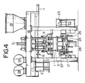
- reference numeral (1) designates a cope core box and numeral (2) a drag core box.
- the cope core box (1) is disengageably mounted by a known clamping mechanism to the lower end of a guide rod which is driven by a lifting cylinder (3) disposed on an upper frame (18) of the machine frame.
- Reference (4) designates a blow head carriage and reference (5) a gassing carriage respectively.
- the carriages (4) and (5) are of the mechanism such that they traverse, by the operation of a traverse cylinder (11), on a rail (7) shown in Fig. 2 and suspended from the lower surface of the upper frame (18).
- the blow head carriage (4) and the gassing carriage (5) are disengageably connected at their facing side by a coupling mechanism such as a connecting pin (6) as shown in Fig. 1, and when the cope core box (1) rises (together with the gassing carriage) said connecting pin (6) is released from the blow head carriage (4) and only the gassing carriage (5) lifts up.
- a coupling mechanism such as a connecting pin (6) as shown in Fig. 1, and when the cope core box (1) rises (together with the gassing carriage) said connecting pin (6) is released from the blow head carriage (4) and only the gassing carriage (5) lifts up.
- Reference (8) is a sand feeding assembly provided between a hopper (19) and the blow head carriage (4).
- Reference (9) is a blow head, reference (10) a gassing head, reference (12) a known press cylinder provided on a connecting frame (33) of the lifting guide rod, reference (13) a press head of the press cylinder (12), reference (14) a blow tank, reference (15) an ejector cylinder for the cope core box, reference (16) a cylinder for tilting the drag core box by 90°, reference (17) a cleaning device of the drag core box, reference (20) a blow plate, reference (21) a blow plate chucking cylinder, reference (22) a cylinder for mounting the cope core box, reference (23) a cleaning device of the blow plate, reference (24) a drag core box chucking cylinder, reference (25) a cylinder used for adjusting a core box removing rail (29) when a core box is replaced, reference (26) a duster tank, reference (27) a frame of the molding machine, and reference (28)
- Figs. 5 to 14 are schematic views illustrating schematically and partly sectionally the relative positional relationships of the operational sequence at a molding operation by the cope core box, the drag core box, the blow head, the gassing head, etc.
- Figs. 3 and 5 are front views of the molding machine when the molding operation has been started.
- the cope core box (1) descends in the state shown in Figs. 3 and 5 as it moves downwardly by means of the lifting cylinder (3) thereby to be clamped onto the drag core box (2).
- the gassing carriage (5) also descends along with the cope core box (1), when the respective wheels of said gassing carriage are pressed against the rail (7), as shown in Figs. 2 and 6, and simultaneously it is connected to the blow head carriage (4) by means of the connecting pin (6) provided at the gassing carriage (5).
- the blow head carriage (4) supplied with sand from hopper (19) by the sand feeding assembly (8) is transferred onto the cope core box by the operation of the traverse cylinder (11). At this time, the gassing carriage (5) in a connected state is pushed out to a waiting position.
- the press head (13) presses the blow head (9) thereby to press the blow plate (20) of said blow head against the upper surface of the cope core box (1).
- a blow valve (not shown) provided on the upper frame (18) is operated, the compressed air within the blow tank (14) is blown under pressure into the blow head (9) through the press head (13), and the molding sand within the blow head (9) is blown into the molding cavities in the core boxes. Then the air in the blow head is exhausted thereafter releasing the pressing of said blow head (9).
- the press head (13) presses the gassing head (10) to press the head (10) against the upper surface of said cope core box (1), and a curing gas is injected under pressure by an ordinary method into the molding sand filled in the clamped core box to allow the molding sand to be hardened.
- a curing gas is injected under pressure by an ordinary method into the molding sand filled in the clamped core box to allow the molding sand to be hardened.
- a core receiving unloader (31) is inserted beneath the cope core box (1), the moulding (30) carried by the cope core box is released by operating the ejector cylinder (15) provided in the gassing carriage (5), and the moulding (30) is received by the unloader (31) so as to be removed. These are the steps of removal the mouldings in Fig. 12.
- the drag core box (2) is tilted by 90° (Fig. 13), and the cleaning device (17) of said drag core box is operated thereby cleaning said drag core box and spraying a mold release agent or the like thereto.
- the cope core box (1) is cleaned, when the unloader is retracted, by the cleaning device provided in the unloader.
- the drag core box (2) is returned by operating the cylinder (16) and transferred to the following molding cycle. This is the return step of the drag core box.
Abstract
Description
- This invention relates to a horizontally parted molding machine in which a drag core box is stationary, and the invention is applicable to various kinds of molding processes such as warm box, hot box, cold box (isocure, SO₂, CO₂, methyl formate, etc.) and shell mold process.
- Horizontally parted molding machines as referred to above are grouped largely into two systems of conventional drag core box lifting system and core box carriage traverse system of carrying out a molding operation by placing a cope core box onto a drag core box.
- As the drag core box lifting molding machines there are known those described in Japanese Patent Publications Nos. 22212/70 and 13255/83 and Utility Model Publications Nos. 1875/85, 1876/85 and 19790/85 which were filed in the name of the applicant of this application.
- As mentioned above, conventional horizontally parted molding machines are of the system where the drag core box is either lifted or traversed, and there has not so far been proposed any horizontally parted molding machine of carrying out a molding operation with stationary drag core box.
- However, the drag core box of a horizontally parted molding machine is usually most heavy among the elements of the machine mechanism, and it requires a great amount of energy to move such a heavy drag core box mechanism. That is, the running cost increases, and these days it is necessary to relieve the impact when a heavy thing is stopped for increasing the machine cycle. Further, these days the size of core boxes is apt to become larger and a working stage is needed for inspecting and cleaning the interior of drag core boxes thereby presenting various problems.
- The inventor of this invention has made extensively his research and experiment in an attempt to remove the various drawbacks of the known horinzontally parted molding machines as referred to above, and as a result, he has been successful in developing the horizontally parted molding machine of the present invention. The technical constitution of the invention relates to a horizontally parted, mold molding machine in which a core box consisting of a pair of a cope core box and a drag core box is provided, and blowing, mold ejection and gassing mechanisms are traversably arranged in the above position of said cope core box, characterised in that the drag core box is stationary. The drag core box mechanism is provided with a mechanism of tilting the drag core box by 90°, and it is also equipped with a mechanism where the gassing mechanism and the blowing mechanism are disengageably connected by a coupling machanism.
- The invention will now be described, by way of example, with reference to the accompanying drawings. Additionally, by the system of stationary drag core box mechanism is meant that said drag core box mechanism does not rise and fall and traverse except when the drag core box is replaced.
- The attached drawings are detailed drawings showing one example of a molding machine of this invention and schematic drawings of relative positional relationships between major memebers being shown in operational sequence.
- Fig. 1 is a front view of a molding machine of this invention;
- Fig. 2 is a side view of the machine in Fig. 1; and
- Fig. 3-14 are detailed views and schematic views showing the operational mode of the molding machine.
- In the drawings, reference numeral (1) designates a cope core box and numeral (2) a drag core box. The cope core box (1) is disengageably mounted by a known clamping mechanism to the lower end of a guide rod which is driven by a lifting cylinder (3) disposed on an upper frame (18) of the machine frame. Reference (4) designates a blow head carriage and reference (5) a gassing carriage respectively. The carriages (4) and (5) are of the mechanism such that they traverse, by the operation of a traverse cylinder (11), on a rail (7) shown in Fig. 2 and suspended from the lower surface of the upper frame (18). The blow head carriage (4) and the gassing carriage (5) are disengageably connected at their facing side by a coupling mechanism such as a connecting pin (6) as shown in Fig. 1, and when the cope core box (1) rises (together with the gassing carriage) said connecting pin (6) is released from the blow head carriage (4) and only the gassing carriage (5) lifts up.
- In Figs. 1 and 2, the major members other than those mentioned above are as follows:
- Reference (8) is a sand feeding assembly provided between a hopper (19) and the blow head carriage (4). Reference (9) is a blow head, reference (10) a gassing head, reference (12) a known press cylinder provided on a connecting frame (33) of the lifting guide rod, reference (13) a press head of the press cylinder (12), reference (14) a blow tank, reference (15) an ejector cylinder for the cope core box, reference (16) a cylinder for tilting the drag core box by 90°, reference (17) a cleaning device of the drag core box, reference (20) a blow plate, reference (21) a blow plate chucking cylinder, reference (22) a cylinder for mounting the cope core box, reference (23) a cleaning device of the blow plate, reference (24) a drag core box chucking cylinder, reference (25) a cylinder used for adjusting a core box removing rail (29) when a core box is replaced, reference (26) a duster tank, reference (27) a frame of the molding machine, and reference (28) a drag ejecting cylinder for operating the ejecting mechanism of mouldings (such as cores), respectively.
- An embodiment of the horizontally parted molding machine of the invention, which is technically constituted as described above, will be described with reference to Figs. 3 to 14.
- Additionally, Figs. 5 to 14 are schematic views illustrating schematically and partly sectionally the relative positional relationships of the operational sequence at a molding operation by the cope core box, the drag core box, the blow head, the gassing head, etc.
- Figs. 3 and 5 are front views of the molding machine when the molding operation has been started. The cope core box (1) descends in the state shown in Figs. 3 and 5 as it moves downwardly by means of the lifting cylinder (3) thereby to be clamped onto the drag core box (2). At that time, the gassing carriage (5) also descends along with the cope core box (1), when the respective wheels of said gassing carriage are pressed against the rail (7), as shown in Figs. 2 and 6, and simultaneously it is connected to the blow head carriage (4) by means of the connecting pin (6) provided at the gassing carriage (5). These are the clamping steps of the cope core box in Fig. 1.
- The blow head carriage (4) supplied with sand from hopper (19) by the sand feeding assembly (8) is transferred onto the cope core box by the operation of the traverse cylinder (11). At this time, the gassing carriage (5) in a connected state is pushed out to a waiting position. These are the traversing steps of the blow head in Figs. 4 and 7.
- By the oepration of the press cylinder (12) the press head (13) presses the blow head (9) thereby to press the blow plate (20) of said blow head against the upper surface of the cope core box (1). Thereafter, a blow valve (not shown) provided on the upper frame (18) is operated, the compressed air within the blow tank (14) is blown under pressure into the blow head (9) through the press head (13), and the molding sand within the blow head (9) is blown into the molding cavities in the core boxes. Then the air in the blow head is exhausted thereafter releasing the pressing of said blow head (9). These are the pressing and blowing steps in Figs. 4 and 8.
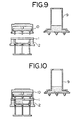
- By the operation of the traverse cylinder (11) the blow head carriage (4) is moved and returned to the sand feeding position, when the gassing carriage (5) connected by the connecting pin (6) transfers to the upper portion of the cope core box of the clamped core box filled with the molding sand and is stopped there. These are the traversing steps of the gassing carriage in Fig. 9.
- By the operation of the press cylinder (12) the press head (13) presses the gassing head (10) to press the head (10) against the upper surface of said cope core box (1), and a curing gas is injected under pressure by an ordinary method into the molding sand filled in the clamped core box to allow the molding sand to be hardened. These are the gassing and hardening steps in Fig. 10. In these steps the ejector pin (15) is inserted into the blow opening so as to trim the surface of the blown sand.
- While raising the cope core box (1) by the operation of the lifting cylinder (3), the core ejecting cylinder (28) of the drag core box (2) is simultaneously operated to eject the moulding (30) from the drag core box (2), and the cope core box (1) is separated from the drag core box (2) while carrying the moulding (30), and ascends in that state. At that time the gassing carriage (5) ascends, too. These are the ascending steps of the cope core box and the gassing carriage in Fig. 11.
- A core receiving unloader (31) is inserted beneath the cope core box (1), the moulding (30) carried by the cope core box is released by operating the ejector cylinder (15) provided in the gassing carriage (5), and the moulding (30) is received by the unloader (31) so as to be removed. These are the steps of removal the mouldings in Fig. 12.
- By the operation of the cylinder (16) the drag core box (2) is tilted by 90° (Fig. 13), and the cleaning device (17) of said drag core box is operated thereby cleaning said drag core box and spraying a mold release agent or the like thereto. These are the steps of tilting the drag core box by 90°, cleaning it and spraying a mold release agent in Fig. 14. The cope core box (1) is cleaned, when the unloader is retracted, by the cleaning device provided in the unloader.
- The drag core box (2) is returned by operating the cylinder (16) and transferred to the following molding cycle. This is the return step of the drag core box.
- Though said operational example has been explained as to a case where the moulding (core) is retained in the cope core box, it will be easily understood by the skilled in the art that it is also possible to eject and remove the moulding while leaving it in the drag core box.
- One example of the molding operation according to the invention has been described above in respect of wet sand process, but in shell mold processing almost the same operation is carried out except non-effecting of said gassing step.
-
- (1) Since the drag core box mechanism that is apt to become large-sized i.e. heavy-weighed is made stationary the power energy needed for driving the heavy article is no longer required. That is, reduction of running cost can be attempted.
- (2) At the present time when increasing the machine cycle of the molding operation is desired it is unnecessary to adopt any impact relieving means when the machine has stopped due to the operation of a heavy article.
- (3) Since the drag core box is stationary even a large-sized drag core box can be inspected, cleaned and so on from above the ground line without needing a working platform.
- (4) Since the drag core box is of 90° tilting system it is easy to dispose the sand remaining in the drag core box and it is possible to prevent the surplus sand from scattering in the molding machine. Then, it is easy to inspect and clean the drag core box by tilting it in a low position.
Claims (3)
- A horizontally parted molding machine which is equipped with a pair of horizontally parted core box consisting of a cope core box (1) and a drag core box (2) and in which blowing, ejecting and gassing mechanisms (4, 5) are traversably arranged in the above position of said cope core box (1) , characterised in that said drag core box (2) is made stationary.
- The horizontally parted molding machine as described in Claim 1 wherein said drag core box mechanism is provided with a mechanism (16) of tilting said drag core box (2) by 90°.
- The horizontally parted molding machine as described in Claim 1 wherein said gassing mechanism (5) and said blowing mechanism (4) are disengageably connected to each other by a connecting mechanism (6).
Applications Claiming Priority (2)
| Application Number | Priority Date | Filing Date | Title |
|---|---|---|---|
| JP44074/90 | 1990-02-23 | ||
| JP2044074A JPH0780037B2 (en) | 1990-02-23 | 1990-02-23 | Lower mold fixed horizontal split mold making machine |
Publications (3)
| Publication Number | Publication Date |
|---|---|
| EP0443287A2 true EP0443287A2 (en) | 1991-08-28 |
| EP0443287A3 EP0443287A3 (en) | 1993-03-17 |
| EP0443287B1 EP0443287B1 (en) | 1995-03-22 |
Family
ID=12681478
Family Applications (1)
| Application Number | Title | Priority Date | Filing Date |
|---|---|---|---|
| EP19900420296 Expired - Lifetime EP0443287B1 (en) | 1990-02-23 | 1990-06-22 | A horizontally parted molding machine of stationary drag core box type |
Country Status (4)
| Country | Link |
|---|---|
| EP (1) | EP0443287B1 (en) |
| JP (1) | JPH0780037B2 (en) |
| DE (1) | DE69018060T2 (en) |
| ES (1) | ES2070299T3 (en) |
Cited By (4)
| Publication number | Priority date | Publication date | Assignee | Title |
|---|---|---|---|---|
| FR2687942A1 (en) * | 1992-02-27 | 1993-09-03 | Peugeot | Method and device for moulding cores from foundry sand containing a curable resin, making it possible to prevent clogging of nozzles for injecting the sand |
| EP0774311A1 (en) * | 1995-11-17 | 1997-05-21 | Sintokogio, Ltd. | Apparatus and method for producing a core |
| WO2002024377A1 (en) * | 2000-09-19 | 2002-03-28 | Georg Fischer Disa A/S | Mould-making machine with means for moving an upper core box to an inspection, cleaning, etc. position |
| CN101304828B (en) * | 2005-12-01 | 2010-09-29 | 兰佩&莫斯纳有限公司 | Method and device for producing moulds or cores, in particular for foundry purposes |
Families Citing this family (4)
| Publication number | Priority date | Publication date | Assignee | Title |
|---|---|---|---|---|
| DE10144193C1 (en) * | 2001-09-08 | 2002-10-31 | Vaw Mandl & Berger Gmbh Linz | Production of molded parts involves pouring a molding material into a molding tool in an injection molding machine |
| TWI482675B (en) * | 2009-12-04 | 2015-05-01 | Sintokogio Ltd | Mold modeling device and mold modeling method |
| CN103170584B (en) * | 2013-04-11 | 2015-01-21 | 苏州苏铸成套装备制造有限公司 | Cold-box core shooter |
| ES2542894B1 (en) * | 2014-02-11 | 2016-08-03 | Loramendi, S.Coop. | Machine and method for manufacturing sand males |
Citations (1)
| Publication number | Priority date | Publication date | Assignee | Title |
|---|---|---|---|---|
| US4700767A (en) * | 1986-05-13 | 1987-10-20 | Guido Peterle | Molding machine for molding-sand cores |
-
1990
- 1990-02-23 JP JP2044074A patent/JPH0780037B2/en not_active Expired - Fee Related
- 1990-06-22 EP EP19900420296 patent/EP0443287B1/en not_active Expired - Lifetime
- 1990-06-22 DE DE1990618060 patent/DE69018060T2/en not_active Expired - Fee Related
- 1990-06-22 ES ES90420296T patent/ES2070299T3/en not_active Expired - Lifetime
Patent Citations (1)
| Publication number | Priority date | Publication date | Assignee | Title |
|---|---|---|---|---|
| US4700767A (en) * | 1986-05-13 | 1987-10-20 | Guido Peterle | Molding machine for molding-sand cores |
Cited By (4)
| Publication number | Priority date | Publication date | Assignee | Title |
|---|---|---|---|---|
| FR2687942A1 (en) * | 1992-02-27 | 1993-09-03 | Peugeot | Method and device for moulding cores from foundry sand containing a curable resin, making it possible to prevent clogging of nozzles for injecting the sand |
| EP0774311A1 (en) * | 1995-11-17 | 1997-05-21 | Sintokogio, Ltd. | Apparatus and method for producing a core |
| WO2002024377A1 (en) * | 2000-09-19 | 2002-03-28 | Georg Fischer Disa A/S | Mould-making machine with means for moving an upper core box to an inspection, cleaning, etc. position |
| CN101304828B (en) * | 2005-12-01 | 2010-09-29 | 兰佩&莫斯纳有限公司 | Method and device for producing moulds or cores, in particular for foundry purposes |
Also Published As
| Publication number | Publication date |
|---|---|
| JPH03254334A (en) | 1991-11-13 |
| EP0443287A3 (en) | 1993-03-17 |
| DE69018060D1 (en) | 1995-04-27 |
| EP0443287B1 (en) | 1995-03-22 |
| DE69018060T2 (en) | 1995-07-27 |
| JPH0780037B2 (en) | 1995-08-30 |
| ES2070299T3 (en) | 1995-06-01 |
Similar Documents
| Publication | Publication Date | Title |
|---|---|---|
| EP0443287B1 (en) | A horizontally parted molding machine of stationary drag core box type | |
| CN110252965A (en) | A kind of sand-mold molding machine conveying device | |
| KR101699150B1 (en) | Shell Removing Apparatus For Lost Wax Casting And Method Thereof | |
| US4840218A (en) | Automatic matchplate molding system | |
| CN210996437U (en) | Sand casting production line | |
| CN111715862B (en) | Method for producing die casting | |
| KR920008673B1 (en) | Molding process and apparatus | |
| CN211193855U (en) | Mould placing rack | |
| US5062465A (en) | Procedure for conveying molds, and a plant for that purpose | |
| JP2946058B2 (en) | Insert molding method and insert molding apparatus | |
| JP3511015B2 (en) | Forging press equipment | |
| KR101765028B1 (en) | Shell Removing Apparatus For Lost Wax Casting And Method Thereof | |
| CN111572067B (en) | Automatic die opening and closing and cleaning device for thermosetting composite material die pressing die | |
| CN210877431U (en) | Full-automatic molding sand molding machine with conveying equipment | |
| JPH0234268A (en) | Method and apparatus for casting cylinder block | |
| CN218134588U (en) | Demolding equipment for noise elimination part | |
| CN215467939U (en) | Flattening device of cold box core shooter | |
| JPS646864B2 (en) | ||
| CN211135502U (en) | Molding sand casting mould conveying equipment | |
| CN210334330U (en) | Ultrasonic vibration water gap cutting machine | |
| JPH1119982A (en) | Method for dismounting molding from vertical rubber injection molding machine | |
| JPH0560653U (en) | Core loader / product takeout device | |
| JPH05177341A (en) | Device for separation product in precision casting equipment | |
| JPH0756100Y2 (en) | Core extrusion equipment in core manufacturing equipment | |
| JPH0713894Y2 (en) | Mold making equipment |
Legal Events
| Date | Code | Title | Description |
|---|---|---|---|
| PUAI | Public reference made under article 153(3) epc to a published international application that has entered the european phase |
Free format text: ORIGINAL CODE: 0009012 |
|
| AK | Designated contracting states |
Kind code of ref document: A2 Designated state(s): DE ES FR GB IT |
|
| PUAL | Search report despatched |
Free format text: ORIGINAL CODE: 0009013 |
|
| AK | Designated contracting states |
Kind code of ref document: A3 Designated state(s): DE ES FR GB IT |
|
| 17P | Request for examination filed |
Effective date: 19930326 |
|
| 17Q | First examination report despatched |
Effective date: 19940125 |
|
| GRAA | (expected) grant |
Free format text: ORIGINAL CODE: 0009210 |
|
| AK | Designated contracting states |
Kind code of ref document: B1 Designated state(s): DE ES FR GB IT |
|
| ITF | It: translation for a ep patent filed |
Owner name: ING. C. CORRADINI & C. S.R.L. |
|
| REF | Corresponds to: |
Ref document number: 69018060 Country of ref document: DE Date of ref document: 19950427 |
|
| REG | Reference to a national code |
Ref country code: ES Ref legal event code: FG2A Ref document number: 2070299 Country of ref document: ES Kind code of ref document: T3 |
|
| ET | Fr: translation filed | ||
| PLBQ | Unpublished change to opponent data |
Free format text: ORIGINAL CODE: EPIDOS OPPO |
|
| PLBI | Opposition filed |
Free format text: ORIGINAL CODE: 0009260 |
|
| PLBF | Reply of patent proprietor to notice(s) of opposition |
Free format text: ORIGINAL CODE: EPIDOS OBSO |
|
| 26 | Opposition filed |
Opponent name: ADOLF HOTTINGER MASCHINENBAU GMBH Effective date: 19951222 |
|
| PLBF | Reply of patent proprietor to notice(s) of opposition |
Free format text: ORIGINAL CODE: EPIDOS OBSO |
|
| PLBF | Reply of patent proprietor to notice(s) of opposition |
Free format text: ORIGINAL CODE: EPIDOS OBSO |
|
| PGFP | Annual fee paid to national office [announced via postgrant information from national office to epo] |
Ref country code: GB Payment date: 19990512 Year of fee payment: 10 |
|
| PGFP | Annual fee paid to national office [announced via postgrant information from national office to epo] |
Ref country code: FR Payment date: 19990519 Year of fee payment: 10 |
|
| PLBO | Opposition rejected |
Free format text: ORIGINAL CODE: EPIDOS REJO |
|
| PLBN | Opposition rejected |
Free format text: ORIGINAL CODE: 0009273 |
|
| STAA | Information on the status of an ep patent application or granted ep patent |
Free format text: STATUS: OPPOSITION REJECTED |
|
| 27O | Opposition rejected |
Effective date: 19990715 |
|
| PG25 | Lapsed in a contracting state [announced via postgrant information from national office to epo] |
Ref country code: GB Free format text: LAPSE BECAUSE OF NON-PAYMENT OF DUE FEES Effective date: 20000622 |
|
| GBPC | Gb: european patent ceased through non-payment of renewal fee |
Effective date: 20000622 |
|
| PG25 | Lapsed in a contracting state [announced via postgrant information from national office to epo] |
Ref country code: FR Free format text: LAPSE BECAUSE OF NON-PAYMENT OF DUE FEES Effective date: 20010228 |
|
| REG | Reference to a national code |
Ref country code: FR Ref legal event code: ST |
|
| PGFP | Annual fee paid to national office [announced via postgrant information from national office to epo] |
Ref country code: DE Payment date: 20010625 Year of fee payment: 12 |
|
| PGFP | Annual fee paid to national office [announced via postgrant information from national office to epo] |
Ref country code: ES Payment date: 20010723 Year of fee payment: 12 |
|
| PG25 | Lapsed in a contracting state [announced via postgrant information from national office to epo] |
Ref country code: ES Free format text: LAPSE BECAUSE OF NON-PAYMENT OF DUE FEES Effective date: 20020623 |
|
| PG25 | Lapsed in a contracting state [announced via postgrant information from national office to epo] |
Ref country code: DE Free format text: LAPSE BECAUSE OF NON-PAYMENT OF DUE FEES Effective date: 20030101 |
|
| REG | Reference to a national code |
Ref country code: ES Ref legal event code: FD2A Effective date: 20030711 |
|
| PG25 | Lapsed in a contracting state [announced via postgrant information from national office to epo] |
Ref country code: IT Free format text: LAPSE BECAUSE OF NON-PAYMENT OF DUE FEES;WARNING: LAPSES OF ITALIAN PATENTS WITH EFFECTIVE DATE BEFORE 2007 MAY HAVE OCCURRED AT ANY TIME BEFORE 2007. THE CORRECT EFFECTIVE DATE MAY BE DIFFERENT FROM THE ONE RECORDED. Effective date: 20050622 |