WO2021261265A1 - Control circuit for power converter - Google Patents
Control circuit for power converter Download PDFInfo
- Publication number
- WO2021261265A1 WO2021261265A1 PCT/JP2021/022063 JP2021022063W WO2021261265A1 WO 2021261265 A1 WO2021261265 A1 WO 2021261265A1 JP 2021022063 W JP2021022063 W JP 2021022063W WO 2021261265 A1 WO2021261265 A1 WO 2021261265A1
- Authority
- WO
- WIPO (PCT)
- Prior art keywords
- switch
- abnormality
- unit
- command
- voltage
- Prior art date
Links
Images


Classifications
-
- H—ELECTRICITY
- H02—GENERATION; CONVERSION OR DISTRIBUTION OF ELECTRIC POWER
- H02P—CONTROL OR REGULATION OF ELECTRIC MOTORS, ELECTRIC GENERATORS OR DYNAMO-ELECTRIC CONVERTERS; CONTROLLING TRANSFORMERS, REACTORS OR CHOKE COILS
- H02P29/00—Arrangements for regulating or controlling electric motors, appropriate for both AC and DC motors
- H02P29/02—Providing protection against overload without automatic interruption of supply
- H02P29/024—Detecting a fault condition, e.g. short circuit, locked rotor, open circuit or loss of load
- H02P29/0241—Detecting a fault condition, e.g. short circuit, locked rotor, open circuit or loss of load the fault being an overvoltage
-
- H—ELECTRICITY
- H02—GENERATION; CONVERSION OR DISTRIBUTION OF ELECTRIC POWER
- H02M—APPARATUS FOR CONVERSION BETWEEN AC AND AC, BETWEEN AC AND DC, OR BETWEEN DC AND DC, AND FOR USE WITH MAINS OR SIMILAR POWER SUPPLY SYSTEMS; CONVERSION OF DC OR AC INPUT POWER INTO SURGE OUTPUT POWER; CONTROL OR REGULATION THEREOF
- H02M7/00—Conversion of ac power input into dc power output; Conversion of dc power input into ac power output
- H02M7/66—Conversion of ac power input into dc power output; Conversion of dc power input into ac power output with possibility of reversal
- H02M7/68—Conversion of ac power input into dc power output; Conversion of dc power input into ac power output with possibility of reversal by static converters
- H02M7/72—Conversion of ac power input into dc power output; Conversion of dc power input into ac power output with possibility of reversal by static converters using discharge tubes with control electrode or semiconductor devices with control electrode
- H02M7/79—Conversion of ac power input into dc power output; Conversion of dc power input into ac power output with possibility of reversal by static converters using discharge tubes with control electrode or semiconductor devices with control electrode using devices of a triode or transistor type requiring continuous application of a control signal
- H02M7/797—Conversion of ac power input into dc power output; Conversion of dc power input into ac power output with possibility of reversal by static converters using discharge tubes with control electrode or semiconductor devices with control electrode using devices of a triode or transistor type requiring continuous application of a control signal using semiconductor devices only
-
- H—ELECTRICITY
- H02—GENERATION; CONVERSION OR DISTRIBUTION OF ELECTRIC POWER
- H02M—APPARATUS FOR CONVERSION BETWEEN AC AND AC, BETWEEN AC AND DC, OR BETWEEN DC AND DC, AND FOR USE WITH MAINS OR SIMILAR POWER SUPPLY SYSTEMS; CONVERSION OF DC OR AC INPUT POWER INTO SURGE OUTPUT POWER; CONTROL OR REGULATION THEREOF
- H02M1/00—Details of apparatus for conversion
- H02M1/08—Circuits specially adapted for the generation of control voltages for semiconductor devices incorporated in static converters
-
- H—ELECTRICITY
- H02—GENERATION; CONVERSION OR DISTRIBUTION OF ELECTRIC POWER
- H02M—APPARATUS FOR CONVERSION BETWEEN AC AND AC, BETWEEN AC AND DC, OR BETWEEN DC AND DC, AND FOR USE WITH MAINS OR SIMILAR POWER SUPPLY SYSTEMS; CONVERSION OF DC OR AC INPUT POWER INTO SURGE OUTPUT POWER; CONTROL OR REGULATION THEREOF
- H02M1/00—Details of apparatus for conversion
- H02M1/32—Means for protecting converters other than automatic disconnection
-
- H—ELECTRICITY
- H02—GENERATION; CONVERSION OR DISTRIBUTION OF ELECTRIC POWER
- H02M—APPARATUS FOR CONVERSION BETWEEN AC AND AC, BETWEEN AC AND DC, OR BETWEEN DC AND DC, AND FOR USE WITH MAINS OR SIMILAR POWER SUPPLY SYSTEMS; CONVERSION OF DC OR AC INPUT POWER INTO SURGE OUTPUT POWER; CONTROL OR REGULATION THEREOF
- H02M7/00—Conversion of ac power input into dc power output; Conversion of dc power input into ac power output
- H02M7/42—Conversion of dc power input into ac power output without possibility of reversal
- H02M7/44—Conversion of dc power input into ac power output without possibility of reversal by static converters
- H02M7/48—Conversion of dc power input into ac power output without possibility of reversal by static converters using discharge tubes with control electrode or semiconductor devices with control electrode
- H02M7/53—Conversion of dc power input into ac power output without possibility of reversal by static converters using discharge tubes with control electrode or semiconductor devices with control electrode using devices of a triode or transistor type requiring continuous application of a control signal
- H02M7/537—Conversion of dc power input into ac power output without possibility of reversal by static converters using discharge tubes with control electrode or semiconductor devices with control electrode using devices of a triode or transistor type requiring continuous application of a control signal using semiconductor devices only, e.g. single switched pulse inverters
- H02M7/5387—Conversion of dc power input into ac power output without possibility of reversal by static converters using discharge tubes with control electrode or semiconductor devices with control electrode using devices of a triode or transistor type requiring continuous application of a control signal using semiconductor devices only, e.g. single switched pulse inverters in a bridge configuration
- H02M7/53871—Conversion of dc power input into ac power output without possibility of reversal by static converters using discharge tubes with control electrode or semiconductor devices with control electrode using devices of a triode or transistor type requiring continuous application of a control signal using semiconductor devices only, e.g. single switched pulse inverters in a bridge configuration with automatic control of output voltage or current
-
- H—ELECTRICITY
- H02—GENERATION; CONVERSION OR DISTRIBUTION OF ELECTRIC POWER
- H02P—CONTROL OR REGULATION OF ELECTRIC MOTORS, ELECTRIC GENERATORS OR DYNAMO-ELECTRIC CONVERTERS; CONTROLLING TRANSFORMERS, REACTORS OR CHOKE COILS
- H02P27/00—Arrangements or methods for the control of AC motors characterised by the kind of supply voltage
- H02P27/04—Arrangements or methods for the control of AC motors characterised by the kind of supply voltage using variable-frequency supply voltage, e.g. inverter or converter supply voltage
- H02P27/06—Arrangements or methods for the control of AC motors characterised by the kind of supply voltage using variable-frequency supply voltage, e.g. inverter or converter supply voltage using dc to ac converters or inverters
-
- H—ELECTRICITY
- H02—GENERATION; CONVERSION OR DISTRIBUTION OF ELECTRIC POWER
- H02P—CONTROL OR REGULATION OF ELECTRIC MOTORS, ELECTRIC GENERATORS OR DYNAMO-ELECTRIC CONVERTERS; CONTROLLING TRANSFORMERS, REACTORS OR CHOKE COILS
- H02P29/00—Arrangements for regulating or controlling electric motors, appropriate for both AC and DC motors
- H02P29/02—Providing protection against overload without automatic interruption of supply
- H02P29/024—Detecting a fault condition, e.g. short circuit, locked rotor, open circuit or loss of load
-
- H—ELECTRICITY
- H02—GENERATION; CONVERSION OR DISTRIBUTION OF ELECTRIC POWER
- H02P—CONTROL OR REGULATION OF ELECTRIC MOTORS, ELECTRIC GENERATORS OR DYNAMO-ELECTRIC CONVERTERS; CONTROLLING TRANSFORMERS, REACTORS OR CHOKE COILS
- H02P3/00—Arrangements for stopping or slowing electric motors, generators, or dynamo-electric converters
- H02P3/06—Arrangements for stopping or slowing electric motors, generators, or dynamo-electric converters for stopping or slowing an individual dynamo-electric motor or dynamo-electric converter
- H02P3/18—Arrangements for stopping or slowing electric motors, generators, or dynamo-electric converters for stopping or slowing an individual dynamo-electric motor or dynamo-electric converter for stopping or slowing an ac motor
-
- H—ELECTRICITY
- H02—GENERATION; CONVERSION OR DISTRIBUTION OF ELECTRIC POWER
- H02M—APPARATUS FOR CONVERSION BETWEEN AC AND AC, BETWEEN AC AND DC, OR BETWEEN DC AND DC, AND FOR USE WITH MAINS OR SIMILAR POWER SUPPLY SYSTEMS; CONVERSION OF DC OR AC INPUT POWER INTO SURGE OUTPUT POWER; CONTROL OR REGULATION THEREOF
- H02M1/00—Details of apparatus for conversion
- H02M1/32—Means for protecting converters other than automatic disconnection
- H02M1/322—Means for rapidly discharging a capacitor of the converter for protecting electrical components or for preventing electrical shock
-
- H—ELECTRICITY
- H02—GENERATION; CONVERSION OR DISTRIBUTION OF ELECTRIC POWER
- H02M—APPARATUS FOR CONVERSION BETWEEN AC AND AC, BETWEEN AC AND DC, OR BETWEEN DC AND DC, AND FOR USE WITH MAINS OR SIMILAR POWER SUPPLY SYSTEMS; CONVERSION OF DC OR AC INPUT POWER INTO SURGE OUTPUT POWER; CONTROL OR REGULATION THEREOF
- H02M1/00—Details of apparatus for conversion
- H02M1/32—Means for protecting converters other than automatic disconnection
- H02M1/327—Means for protecting converters other than automatic disconnection against abnormal temperatures
-
- H—ELECTRICITY
- H02—GENERATION; CONVERSION OR DISTRIBUTION OF ELECTRIC POWER
- H02M—APPARATUS FOR CONVERSION BETWEEN AC AND AC, BETWEEN AC AND DC, OR BETWEEN DC AND DC, AND FOR USE WITH MAINS OR SIMILAR POWER SUPPLY SYSTEMS; CONVERSION OF DC OR AC INPUT POWER INTO SURGE OUTPUT POWER; CONTROL OR REGULATION THEREOF
- H02M1/00—Details of apparatus for conversion
- H02M1/36—Means for starting or stopping converters
Definitions
- the present disclosure applies to a system comprising a power converter electrically connected to the windings of a rotating electric machine, a power source, and a storage unit connected to an electrical path connecting the power source and the power converter. Regarding the control circuit of the power converter.
- a shutdown control that forcibly turns off the switches of the upper and lower arms constituting the power converter when it is determined that an abnormality has occurred in the system.
- the shutdown control is executed, if a counter electromotive voltage is generated in the winding due to the rotation of the rotor constituting the rotary electric machine, the line voltage of the winding may be higher than the voltage of the power storage unit.
- the situation where the line voltage is high can occur, for example, when the amount of field magnetic flux of the rotor is large or the rotation speed of the rotor is high.
- control circuit described in Patent Document 1 turns on the switch in one of the upper and lower arms and switches in the other arm in order to prevent the occurrence of power regeneration. Executes short-circuit control to turn off.
- Some systems equipped with a rotary electric machine and a power converter are equipped with a cutoff switch such as a relay provided in an electric path connecting the power supply and the power converter.
- the power storage unit is connected to the cutoff switch on the opposite side of the electric path from the power supply.
- short-circuit control to prevent the occurrence of power regeneration and switching to the off state of the cutoff switch are performed in order to protect the system.
- the cutoff switch is switched to the off state before the short-circuit control is performed, the storage unit is charged by the counter electromotive force generated by the rotary electric machine, and the voltage of the storage unit rises sharply.
- the capacity of the power storage unit rises sharply.
- the cost, physique, weight, and the like of the power storage unit increase.
- the configuration for preventing the occurrence of power regeneration is not limited to short-circuit control.
- the main object of the present disclosure is to provide a control circuit of a power converter that can protect a power storage unit and a power converter.
- This disclosure describes the rotary electric machine and A power converter electrically connected to the winding of the rotary electric machine, and Power supply and A cutoff switch provided in an electric path connecting the power supply and the power converter,
- a control circuit of a power converter applied to a system including a power storage unit connected to the cutoff switch on the side opposite to the power supply in the electric path.
- An abnormality determination unit that determines whether or not an abnormality has occurred in the system
- a regenerative prevention unit for preventing the generation of electric power regeneration in which a current flows from the rotary electric machine side to the power storage unit is provided.
- the cutoff switch is switched to the off state after the generation of the power regeneration is prevented by the regeneration prevention unit.
- the present disclosure includes an abnormality determination unit that determines whether or not an abnormality has occurred in the system, and a regeneration prevention unit that prevents the occurrence of power regeneration.
- an abnormality determination unit that determines whether or not an abnormality has occurred in the system
- a regeneration prevention unit that prevents the occurrence of power regeneration.
- the cutoff switch is switched to the off state after the generation of power regeneration is prevented by the regeneration prevention unit.
- the regeneration prevention unit it is possible to prevent the voltage of the power storage unit from rising sharply, and it is possible to protect the power storage unit and the power converter.
- FIG. 1 is an overall configuration diagram of a control system according to the first embodiment.
- FIG. 2 is a diagram showing a control circuit and its peripheral configuration.
- FIG. 3 is a diagram showing the upper and lower arm drivers and their peripheral configurations.
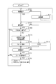
- FIG. 4 is a flowchart showing a processing procedure of three-phase short-circuit control and shutdown control executed by the microcomputer.
- FIG. 5 is a time chart showing an example of processing modes of three-phase short-circuit control and shutdown control.
- FIG. 6 is a flowchart showing the procedure of the check process executed by the microcomputer.
- FIG. 7 is a time chart showing an example of the check processing mode in the end sequence.
- FIG. 8 is an overall configuration diagram of the control system according to the second embodiment.
- FIG. 9 is a diagram showing a control circuit and its peripheral configuration.
- FIG. 10 is a diagram showing the upper and lower arm drivers and their peripheral configurations.
- FIG. 11 is a diagram showing an OR circuit, a power supply stop unit, and their peripheral configurations.
- FIG. 12 is a flowchart showing the processing procedure of the three-phase short circuit control.
- FIG. 13 is a time chart showing an example of three-phase short-circuit control.
- FIG. 14 is a flowchart showing a processing procedure of three-phase short-circuit control and shutdown control executed by the microcomputer.
- FIG. 9 is a diagram showing a control circuit and its peripheral configuration.
- FIG. 10 is a diagram showing the upper and lower arm drivers and their peripheral configurations.
- FIG. 11 is a diagram showing an OR circuit, a power supply stop unit, and their
- FIG. 15 is a flowchart showing the procedure of the check process executed by the microcomputer.
- FIG. 16 is an overall configuration diagram of the control system according to the third embodiment.
- FIG. 17 is a flowchart showing a procedure of processing executed by the microcomputer.
- FIG. 18 is a flowchart showing the procedure of the check process executed by the microcomputer.
- FIG. 19 is an overall configuration diagram of the control system according to the fourth embodiment.
- FIG. 20 is a flowchart showing a procedure of processing executed by the microcomputer.
- FIG. 21 is a flowchart showing the procedure of the check process executed by the microcomputer.
- FIG. 22 is an overall configuration diagram of a control system according to another embodiment.
- control circuit according to the present disclosure is embodied
- the control circuit according to this embodiment is applied to a three-phase inverter as a power converter.
- the control system including the inverter is mounted on a vehicle such as an electric vehicle or a hybrid vehicle.
- the control system includes a rotary electric machine 10 and an inverter 15.
- the rotary electric machine 10 is an in-vehicle main engine, and its rotor is capable of transmitting power to drive wheels (not shown).
- a synchronous machine is used as the rotary electric machine 10, and more specifically, a permanent magnet synchronous machine is used.
- the inverter 15 includes a switching device unit 20.
- the switching device unit 20 includes a series connection body of the upper arm switch SWH and the lower arm switch SWL for three phases. In each phase, the first end of the winding 11 of the rotary electric machine 10 is connected to the connection points of the upper and lower arm switches SWH and SWL. The second end of each phase winding 11 is connected at a neutral point.
- the phase windings 11 are arranged so as to be offset by 120 ° from each other by the electric angle.
- a voltage-controlled semiconductor switching element is used as each switch SWH and SWL, and more specifically, an IGBT is used.
- the upper and lower arm diodes DH and DL which are freewheel diodes, are connected in antiparallel to the upper and lower arm switches SWH and SWL.
- the positive electrode terminal of the high voltage power supply 30 is connected to the collector, which is the high potential side terminal of each upper arm switch SWH, via the high potential side electric path 22H.
- the negative electrode terminal of the high-voltage power supply 30 is connected to the emitter, which is the low-potential side terminal of each lower arm switch SWL, via the low-potential side electric path 22L.
- the high voltage power supply 30 is a secondary battery, and its output voltage (rated voltage) is, for example, 100 V or more.
- the high potential side electric path 22H is provided with a first cutoff switch 23a, and the low potential side electric path 22L is provided with a second cutoff switch 23b.
- the switches 23a and 23b are relays.
- the control system includes a precharge switch 23p and a precharge resistor 27.
- the precharge switch 23p is a relay.
- the precharge switch 23p and the precharge resistor 27 are connected in series.
- the series connection body of the precharge switch 23p and the precharge resistor 27 is connected in parallel to the first cutoff switch 23a.
- the inverter 15 includes a smoothing capacitor 24 as a "storage unit".
- the smoothing capacitor 24 electrically connects the switching device section 20 side of the high potential side electric path 22H with respect to the first cutoff switch 23a and the switching device section 20 side of the low potential side electric path 22L with respect to the second cutoff switch 23b. Is connected.
- the control system is equipped with an in-vehicle electric device 25.
- the electrical device 25 includes, for example, at least one of an electric compressor and a DCDC converter.
- the electric compressor constitutes an air conditioner in the vehicle interior and is driven by being supplied with power from a high-voltage power source 30 in order to circulate the refrigerant in the in-vehicle refrigeration cycle.
- the DCDC converter steps down the output voltage of the high-voltage power supply 30 and supplies it to the vehicle-mounted low-voltage load.
- the low voltage load includes the low voltage power supply 31 shown in FIG.
- the low voltage power supply 31 is a secondary battery whose output voltage (rated voltage) is lower than the output voltage (rated voltage) of the high voltage power supply 30, for example, a lead storage battery.
- the inverter 15 includes a discharge resistor 26.
- the discharge resistor 26 has a switching device section 20 side of the high potential side electric path 22H from the first cutoff switch 23a and a switching device section 20 side of the low potential side electric path 22L of the second cutoff switch 23b. It is electrically connected.
- the control system includes a start switch 28.
- the start switch 28 is, for example, an ignition switch or a push-type start switch, and is operated by a user of the vehicle.
- the control system includes a phase current sensor 40, an angle sensor 41, and a temperature sensor 42.
- the phase current sensor 40 outputs a current signal corresponding to the current of at least two phases of each phase current flowing through the rotary electric machine 10.
- the angle sensor 41 outputs an angle signal according to the electric angle of the rotary electric machine 10.
- the angle sensor 41 is, for example, an MR sensor having a resolver, an encoder, or a magnetoresistive sensor, and is a resolver in this embodiment.
- the temperature sensor 42 outputs a temperature signal according to the temperature of a component of the control system such as a component of the rotary electric machine 10.
- the configuration of the control circuit 50 will be described with reference to FIG.
- the control circuit 50 includes an input circuit 61, an intermediate power supply circuit 62, and first to fifth low voltage power supply circuits 63 to 67.
- the positive electrode terminal of the low voltage power supply 31 is connected to the input circuit 61 via the fuse 32 and the power supply switch 33.
- a ground as a grounding portion is connected to the negative electrode terminal of the low voltage power supply 31.
- the host ECU (not shown), which is a control device higher than the control circuit 50, determines that the start switch 28 has been switched to the ON state, the power switch 33 is switched to the ON state. As a result, power supply from the low voltage power supply 31 to the control circuit 50 is started.
- the host ECU determines that the start switch 28 has been switched to the off state
- the host ECU switches the power switch 33 to the off state. Specifically, when the host ECU determines that the start switch 28 has been switched to the off state, the host ECU switches the power switch 33 to the off state after a predetermined end sequence process. As a result, the power supply from the low voltage power supply 31 to the control circuit 50 is stopped.
- the intermediate power supply circuit 62 generates an intermediate voltage Vm (for example, 6V) by stepping down the output voltage VB of the input circuit 61.
- the first low voltage power supply circuit 63 generates a first voltage V1r (for example, 5V) by stepping down the output voltage Vm of the intermediate power supply circuit 62.
- the second low voltage power supply circuit 64 generates a second voltage V2r (for example, 3.3V) by stepping down the first voltage V1r output from the first low voltage power supply circuit 63.
- the third low voltage power supply circuit 65 generates a third voltage V3r by stepping down the first voltage V1r output from the first low voltage power supply circuit 63.
- the third voltage V3r is a voltage lower than the second voltage V2r (for example, 1.2V).
- the fourth low voltage power supply circuit 66 generates a fourth voltage V4r (for example, 5V) by stepping down the output voltage VB of the input circuit 61.
- the fourth voltage V4r has the same value as the first voltage V1r.
- the fifth low voltage power supply circuit 67 generates a fifth voltage V5r (for example, 30V) by boosting the output voltage VB of the input circuit 61.
- the input circuit 61 and the power supply circuits 62 to 67 are provided in the low voltage region of the control circuit 50.
- the first voltage V1r of the first low voltage power supply circuit 63 is supplied to the phase current sensor 40.
- the phase current sensor 40 can output a current signal corresponding to the phase current.
- the current signal is input to the microcomputer 60 via the current interface unit 70 included in the control circuit 50.
- the microcomputer 60 calculates the phase current based on the input current signal.
- the control circuit 50 includes an excitation circuit 71, an FB interface unit 72, and a resolver digital converter 73.
- the excitation circuit 71 is configured to be operable by supplying the fifth voltage V5r of the fifth low voltage power supply circuit 67.
- the excitation circuit 71 supplies a sinusoidal excitation signal to the resolver stator constituting the angle sensor 41.
- the angle signal output from the resolver stator is input to the resolver digital converter 73 via the FB interface unit 72.
- the FB interface unit 72 and the resolver digital converter 73 are configured to be operable by supplying the first voltage V1r of the first low voltage power supply circuit 63.
- the resolver digital converter 73 calculates the electric angle of the rotary electric machine 10 based on the angle signal from the FB interface unit 72.
- the calculated electric angle is input to the microcomputer 60.
- the microcomputer 60 calculates the electric angular velocity of the rotary electric machine 10 based on the input electric angle.
- the control circuit 50 includes a temperature interface unit 74.
- the temperature signal output from the temperature sensor 42 is input to the microcomputer 60 via the temperature interface unit 74.
- the temperature interface unit 74 is configured to be operable by supplying the first voltage V1r of the first low voltage power supply circuit 63.
- the microcomputer 60 calculates the temperature of the detection target of the temperature sensor 42 based on the input temperature signal.
- the control circuit 50 includes first and second CAN transceivers 75 and 76.
- the first and second CAN transceivers 75 and 76 are configured to be operable by supplying the first voltage V1r of the first low voltage power supply circuit 63.
- the microcomputer 60 exchanges information via the first and second CAN transceivers 75 and 76 and the first and second CAN buses 43 and 44.
- the current interface unit 70, the excitation circuit 71, the FB interface unit 72, the resolver digital converter 73, the temperature interface unit 74, and the first and second CAN transceivers 75 and 76 are provided in the low voltage region of the control circuit 50.
- the microcomputer 60 is provided in a low voltage region and includes a CPU and other peripheral circuits.
- the peripheral circuit includes, for example, an input / output unit for exchanging signals with the outside and an AD conversion unit.
- the microcomputer 60 is supplied with the first voltage V1r of the first low voltage power supply circuit 63, the second voltage V2r of the second low voltage power supply circuit 64, and the third voltage V3r of the third low voltage power supply circuit 65.
- the control circuit 50 includes a voltage sensor 77, an overvoltage detection unit 78, and a state determination unit 79.
- the voltage sensor 77 is electrically connected to the high potential side electric path 22H and the low potential side electric path 22L, and the output voltage VB of the input circuit 61 and the fifth voltage V5r of the fifth low voltage power supply circuit 67 are supplied. It is configured to be operational.
- the voltage sensor 77 outputs a voltage signal corresponding to the terminal voltage of the smoothing capacitor 24.
- the voltage signal output from the voltage sensor 77 is input to the microcomputer 60 and the overvoltage detection unit 78.
- the overvoltage detection unit 78 is configured to be operable by supplying the first voltage V1r of the first low voltage power supply circuit 63.
- the overvoltage detection unit 78 determines whether or not the terminal voltage of the smoothing capacitor 24 calculated based on the input voltage signal exceeds the upper limit voltage thereof.
- the overvoltage detection unit 78 outputs an overvoltage signal to the microcomputer 60 and the state determination unit 79.
- the state determination unit 79 is configured to be operable by supplying the first voltage V1r of the first low voltage power supply circuit 63. Further, in the present embodiment, the state determination unit 79 is composed of a logic circuit. The voltage sensor 77, the overvoltage detection unit 78, and the state determination unit 79 are provided in the low voltage region of the control circuit 50.
- the microcomputer 60 functions as a switching command generation unit that generates a switching command for each switch SWH and SWL of the switching device unit 20 in order to control the control amount of the rotary electric machine 10 to the command value.
- the control amount is, for example, torque.
- the microcomputer 60 generates a switching command based on the output signals of the sensors 40 to 42, 77 and the like.
- the microcomputer 60 generates a switching command in which the upper arm switch SWH and the lower arm switch SWL are alternately turned on in each phase.
- the control circuit 50 includes an isolated power supply 80, an upper arm driver 81, and a lower arm driver 82.
- the upper arm driver 81 is individually provided corresponding to each upper arm switch SWH
- the lower arm driver 82 is individually provided corresponding to each lower arm switch SWL. Therefore, a total of six drivers 81 and 82 are provided.
- the isolated power supply 80 generates and outputs an upper arm drive voltage VdH supplied to the upper arm driver 81 and a lower arm drive voltage VdL supplied to the lower arm driver 82 based on the voltage supplied from the input circuit 61. ..
- the insulated power supply 80 and the drivers 81 and 82 are provided in the low voltage region and the high voltage region across the boundary between the low voltage region and the high voltage region in the control circuit 50.
- the insulated power supply 80 includes an upper arm insulated power supply individually provided for each of the three-phase upper arm drivers 81, and a lower arm insulated power supply common to the three-phase lower arm driver 82. There is.
- each upper arm insulated power supply and lower arm insulated power supply are controlled by a common power supply control unit.
- the lower arm insulated power supply may be individually provided for each of the three-phase lower arm drivers 82.
- the upper arm driver 81 includes an upper arm drive unit 81a as a switch drive unit and an upper arm insulation transmission unit 81b.
- the upper arm drive unit 81a is provided in a high pressure region.
- the upper arm insulation transmission portion 81b is provided in the low pressure region and the high pressure region across the boundary between the low pressure region and the high pressure region.
- the upper arm insulation transmission unit 81b transmits a switching command output from the microcomputer 60 to the upper arm drive unit 81a while electrically insulating between the low voltage region and the high voltage region.
- the upper arm insulation transmission unit 81b is, for example, a photocoupler or a magnetic coupler.
- the configuration of the upper arm drive unit 81a and the upper arm insulation transmission unit 81b on the high voltage region side is configured to be operable by supplying the upper arm drive voltage VdH of the insulation power supply 80.
- the configuration of the upper arm insulation transmission portion 81b on the low voltage region side is configured to be operable by supplying the first voltage V1r of the first low voltage power supply circuit 63.
- the upper arm drive unit 81a supplies a charging current to the gate of the upper arm switch SWH when the input switching command is an on command. As a result, the gate voltage of the upper arm switch SWH becomes equal to or higher than the threshold voltage Vth, and the upper arm switch SWH is turned on. On the other hand, when the input switching command is an off command, the upper arm drive unit 81a causes a discharge current to flow from the gate of the upper arm switch SWH to the emitter side. As a result, the gate voltage of the upper arm switch SWH becomes less than the threshold voltage Vth, and the upper arm switch SWH is turned off.
- the upper arm drive unit 81a transmits the fail signal Sgfail, which is information indicating that an abnormality has occurred in the upper arm switch SWH, and the temperature Tswd information of the upper arm switch SWH, via the upper arm insulation transmission unit 81b. Communicate to 60.
- the abnormality of the upper arm switch SWH includes at least one of an overheating abnormality, an overvoltage abnormality, and an overcurrent abnormality.
- the upper arm driver 81 transmits the final switching command SWM Whyn in the low voltage region to the upper arm switch SWH to the microcomputer 60.
- the final switching commands are a switching command output from the microcomputer 60 to the upper arm insulation transmission unit 81b and a shutdown command CmdSDN output from the state determination unit 79 to the upper arm insulation transmission unit 81b. It is a logical operation value of.
- the on command is output as the switching command from the microcomputer 60
- the final switching command SWM obviouslyn is set as the on command.
- an off command is output as a switching command from the microcomputer 60
- the final switching command SWM Whyn is set as an off command.
- the lower arm driver 82 includes a lower arm drive unit 82a as a switch drive unit and a lower arm insulation transmission unit 82b.
- the configurations of the drivers 81 and 82 are basically the same. Therefore, in the following, detailed description of the lower arm driver 82 will be omitted as appropriate.
- the configuration of the lower arm drive unit 82a and the lower arm insulation transmission unit 82b on the high voltage region side are configured to be operable by supplying the lower arm drive voltage VdL of the insulation power supply 80.
- the configuration of the lower arm insulation transmission portion 82b on the low voltage region side is configured to be operable by supplying the first voltage V1r of the first low voltage power supply circuit 63.
- the lower arm drive unit 82a supplies a charging current to the gate of the lower arm switch SWL when the input switching command is an on command. As a result, the gate voltage of the lower arm switch SWL becomes equal to or higher than the threshold voltage Vth, and the lower arm switch SWL is turned on. On the other hand, when the input switching command is an off command, the lower arm drive unit 82a causes a discharge current to flow from the gate of the lower arm switch SWL to the emitter side. As a result, the gate voltage of the lower arm switch SWL becomes less than the threshold voltage Vth, and the lower arm switch SWL is turned off.
- the lower arm drive unit 82a transmits the fail signal Sgfail, which is information indicating that an abnormality has occurred in the lower arm switch SWL, and the temperature Tswd information of the lower arm switch SWL, via the lower arm insulation transmission unit 82b. Communicate to 60.
- the abnormality of the lower arm switch SWL includes at least one of an overheating abnormality, an overvoltage abnormality and an overcurrent abnormality.
- the control circuit 50 includes a fail detection unit 83.
- the fail detection unit 83 is provided in the low voltage region, and the fail signal Sgfail from each of the drivers 81 and 82 is input.
- the fail detection unit 83 outputs an abnormality signal to the microcomputer 60 and the state determination unit 79.
- the abnormal signal input to the microcomputer 60 is stored in the memory 60a as a storage unit included in the microcomputer 60.
- the memory 60a is a non-transitional substantive recording medium other than the ROM (for example, a non-volatile memory other than the ROM).
- the lower arm driver 82 transmits the final switching command SWM Whyn in the low voltage region to the lower arm switch SWL to the microcomputer 60.
- the final switching commands are a switching command output from the microcomputer 60 to the lower arm insulation transmission unit 82b and a shutdown command CmdSDN output from the state determination unit 79 to the lower arm insulation transmission unit 82b. It is a logical operation value of.
- the monitoring unit 85 is provided in a low voltage region and is configured to be operable by supplying the output voltage VB of the input circuit 61.
- the monitoring unit 85 has a function of monitoring whether or not an abnormality has occurred in the microcomputer 60, and is composed of, for example, a watch dock counter (WDC) or a function watch dock counter (F-WDC).
- the control circuit 50 includes a relay controller 45.
- the relay controller 45 is provided in the low voltage region.
- the relay controller 45 determines that a relay on command (corresponding to a "switch on command") has been input from the microcomputer 60
- the relay controller 45 outputs an on command to the first and second cutoff switches 23a and 23b for precharging.
- An off command is output to the switch 23p.
- the relay controller 45 determines that a relay off command (corresponding to a "switch off command”) has been input from the microcomputer 60
- the relay controller 45 issues an off command to the first and second cutoff switches 23a and 23b and the precharge switch 23p. Output.
- the first and second cutoff switches 23a and 23b and the precharge switch 23p are turned off.
- the relay controller 45 determines that the precharge command has been input from the microcomputer 60, the relay controller 45 executes the precharge process of the smoothing capacitor 24.
- This process is a process of turning on the precharge switch 23p and the second shutoff switch 23b while turning off the first shutoff switch 23a. According to the precharge process, it is possible to prevent an inrush current from flowing through the smoothing capacitor 24.
- the state determination unit 79 determines whether or not an overvoltage signal from the overvoltage detection unit 78 or an abnormal signal from the fail detection unit 83 has been input.
- the shutdown command CmdSDN for turning off the upper and lower arm switches SWH and SWL for three phases is issued to the upper and lower arm drivers 81 for three phases. , 82 is output. As a result, shutdown control is executed.
- the microcomputer 60 executes three-phase short-circuit control.
- the three-phase short-circuit control process and the shutdown control process executed by the microcomputer 60 will be described with reference to FIG.
- the three-phase short-circuit control is also called ASC (Active Short Circuit) control.
- step S10 it is determined whether or not an abnormality has occurred in the control system.
- the abnormality of the control system includes the abnormality of the upper and lower arm switches SWH and SWL.
- the abnormality of the control system includes a sensor abnormality or a communication abnormality.
- the sensor abnormality includes at least one abnormality of the phase current sensor 40, the angle sensor 41, the temperature sensor 42, and the voltage sensor 77.
- the abnormality of the phase current sensor 40 includes at least one abnormality of the phase current sensor 40 itself and an abnormality of the current interface unit 70.
- the abnormality of the angle sensor 41 includes at least one of the abnormality of the angle sensor 41 itself, the abnormality of the excitation circuit 71, the abnormality of the FB interface unit 72, and the abnormality of the resolver digital converter 73.
- the abnormality of the temperature sensor 42 includes at least one abnormality of the temperature sensor 42 itself and an abnormality of the temperature interface unit 74.
- the communication abnormality includes at least one abnormality of the first CAN transceiver 75, the second CAN transceiver 76, the first CAN bus 43, and the second CAN bus 44.
- step S10 corresponds to the "abnormality determination unit".
- step S10 If it is determined in step S10 that no abnormality has occurred, the process proceeds to step S11, a relay-on command is output to the relay controller 45, and normal control is performed.
- the normal control is a control for generating and outputting a switching command for controlling the control amount of the rotary electric machine 10 to a command value in order to drive the vehicle.
- the relay on command By the relay on command, the first and second cutoff switches 23a and 23b are turned on, and the precharge switch 23p is turned off.
- step S10 determines whether or not that abnormality has occurred. If it is determined in step S10 that any abnormality has occurred, the process proceeds to step S12, and is power regeneration occurring, which is a phenomenon in which a current flows from the rotary electric machine 10 side in the direction of the smoothing capacitor 24? Judge whether or not.
- the line voltage Vdemf when a counter electromotive voltage is generated in the winding 11 is estimated and it is determined that the estimated line voltage Vdemf exceeds the high voltage side power supply voltage Vdc, the power regeneration occurs. It may be determined that it has occurred.
- the high-voltage side power supply voltage Vdc is the terminal voltage of the smoothing capacitor 24 calculated based on the voltage signal of the voltage sensor 77.
- K is a constant and is a value determined from the magnetic flux amount ⁇ of the magnetic pole of the rotor.
- the line voltage Vdemf may be estimated based on, for example, the mechanical angular velocity of the rotor instead of the electric angular velocity ⁇ e. Further, the line voltage Vdemf may be estimated by further using the detection value of the temperature sensor that detects the temperature of the rotor of the rotary electric machine 10 or the estimation value of the temperature estimation unit that estimates the temperature of the rotor.
- the value to be compared with the line voltage Vdemf is not limited to the calculated high voltage side power supply voltage Vdc, and may be, for example, a predetermined determination value.
- the determination value may be set to, for example, the minimum value within the range in which the normal value of the terminal voltage of the high voltage power supply 30 can be taken.
- step S12 corresponds to the "safety state determination unit".
- step S12 If it is determined in step S12 that power regeneration has not occurred, it is determined that the control that puts the inverter 15 in a safe state is shutdown control, and the process proceeds to step S13.
- step S13 an off command is output as a switching command for the upper and lower arm switches SWH and SWL for three phases. As a result, shutdown control that prevents the occurrence of power regeneration is executed.
- step S14 it is determined whether or not the abnormality determined in step S10 has been resolved. If it is determined that the abnormality is not resolved, the process proceeds to step S12. On the other hand, when it is determined that the abnormality has been resolved, the process proceeds to step S15, and the process of step S18 described later is performed in the period from the determination that the abnormality has occurred in step S10 to the determination that the abnormality has been resolved in step S14. Therefore, it is determined whether or not the relay off command is output to the relay controller 45. If it is determined in step S15 that the relay off command has not been output, the process proceeds to step S10.
- the shutdown control is executed during the period from the determination that the abnormality has occurred in step S10 to the determination that the abnormality has been resolved in step S14 (hereinafter referred to as the abnormality occurrence period).
- the relay-on command (corresponding to the “switch-on command”) is continuously output from the microcomputer 60 to the relay controller 45 during the abnormality occurrence period, and the first and second cutoff switches 23a and 23b are maintained in the on state. Shut down.
- step S12 If it is determined in step S12 that power regeneration has occurred, it is determined that the control that puts the inverter 15 in a safe state is three-phase short-circuit control, and the process proceeds to step S16. In step S16, it is determined whether or not the three-phase short circuit control is being executed.
- step S17 an off command is output as a switching command for one of the upper and lower arm switches SWH and SWL for three phases (hereinafter, off-side switch), and the other arm switch (hereinafter, on-side switch) is output. ) Is output as an on command as a switching command.
- step S17 an affirmative determination is made in the next step S16.
- the switching command in step S17 corresponds to the "regeneration prevention command".
- an off command is output as a switching command for the upper arm switch SWH for three phases
- an on command is output as a switching command for the lower arm switch SWL for three phases.
- the abnormality may be as follows according to the short abnormality or the open abnormality.
- an on command is output as a switching command for the switches for the three phases of the arm in which the short-circuit error has occurred in the upper and lower arms.
- an off command is output as a switching command for the switches for the three phases of the other arm.
- step S18 a relay off command is output to the relay controller 45 in order to switch the first and second cutoff switches 23a and 23b to the off state. After that, the process proceeds to step S14.
- step S18 If the process of step S18 is completed, or if it is determined in step S16 that the three-phase short-circuit control is being executed, the process proceeds to step S14. If it is determined in step S14 that the abnormality determined in step S10 is not resolved, the process proceeds to step S12. On the other hand, when it is determined that the abnormality has been resolved, the process proceeds to step S15, and during the period from the determination that the abnormality has occurred in step S10 to the determination that the abnormality has been resolved in step S14, the relay is relayed by the processing of step S18. It is determined whether or not the relay off command is output to the controller 45.
- step S15 If it is determined that the relay off command has been output in step S15, the process proceeds to step S19.
- step S19 first, a precharge command is output to the relay controller 45. As a result, the precharge process is executed. After that, a relay on command is output to the relay controller 45.
- the microcomputer 60 and the relay controller 45 correspond to the "abnormality control unit".
- FIG. 5A shows the transition of the output voltage VB of the input circuit 61
- FIG. 5B shows the transition of the drive states of the first and second cutoff switches 23a and 23b and the precharge switch 23p
- FIG. (C) shows the transition of the terminal voltage VH of the smoothing capacitor 24
- FIG. 5D shows the transition of the operating state of the microcomputer 60
- FIG. 5E shows the transition of the operating state of the inverter 15.
- the off commands for the upper and lower arm switches SWH and SWL for the three phases are output and the shutdown control is executed, and then the three-phase short-circuit control is performed. Will be executed. This is to prevent the occurrence of a short circuit between the upper and lower arms.
- the relay off command is output from the microcomputer 60 to the relay controller 45, so that the first and second cutoff switches 23a and 23b are switched to the off state.
- the discharge current of the smoothing capacitor 24 flows through the discharge resistor 26, so that the terminal voltage of the smoothing capacitor 24 gradually decreases.
- the microcomputer 60 determines that the control that puts the inverter 15 in a safe state is the shutdown control, and an off command is output from the microcomputer 60 as a switching command for the upper and lower arm switches SWH and SWL for three phases. To. As a result, the upper and lower arm switches SWH and SWL are turned off.
- step S20 the rotary electric machine 10 is stopped.
- the stop process is executed when the control system is instructed to stop, and in the present embodiment, the stop process is a process of outputting an off command as a switching command for the upper and lower arm switches SWH and SWL for three phases.
- the host ECU determines that the start switch 28 has been turned off
- the host ECU instructs the microcomputer 60 to execute this stop process.
- the microcomputer 60 determines that the stop processing is instructed to be executed, the microcomputer 60 determines that the control system is instructed to stop, and executes a predetermined termination sequence.
- step S21 the rotor of the rotary electric machine 10 is waited until the rotation is stopped.
- whether or not the rotation of the rotor has stopped may be determined based on, for example, the electric angular velocity.
- step S22 a process simulating the process to be executed when it is determined that an abnormality has occurred in the control system is executed.
- an off command is output as a switching command for the off side switch
- an on command is output as a switching command for the on side switch.
- the off command or the on command is input, and the lower arm drive units 81a and 82a correspond to the "regeneration prevention unit".
- step S23 it is checked that the on-side switch for three phases is turned on and the off-side switch for three phases is turned off by the process of step S22.
- the check method in step S23 will be described.
- This checking method is based on the gate voltage of the switch and the voltage between the collector and the emitter. Specifically, both the condition that the gate voltage of the off-side switch is equal to or less than the off-determination voltage and the condition that the collector-emitter voltage of the off-side switch is near the terminal voltage of the high-voltage power supply 30 are satisfied. If it is determined that the switch is off, it is determined that the off-side switch is in the off state.
- the off determination voltage may be set to a value less than the threshold voltage Vth, for example.
- the ON determination voltage may be set to, for example, the same value as the threshold voltage Vth, or a value larger than the threshold voltage Vth and less than the output voltage of the isolated power supply 80.
- the on determination voltage may be set to a value larger than the threshold voltage Vth and less than the lower arm drive voltage VdL, for example.
- This check method is based on the final switching command SWMegan and the abnormal signal output from the fail detection unit 83. Specifically, when it is determined that both the condition that the final switching command SWM réellen for the off-side switch is the off command and the condition that the abnormal signal is not stored in the memory 60a are satisfied. , Determines that the off-side switch is turned off.
- the on-side switch and the off-side switch are in the intended drive state using the result when the normal control for controlling the torque of the rotary electric machine 10 to the command value is executed. Can be determined.
- step S23 When it is determined in step S23 that the on-side switch for three phases is on and the off-side switch for three phases is in the off state, it is determined that the three-phase short-circuit control can be normally executed.
- step S24 a process simulating the process to be executed when it is determined that an abnormality has occurred in the control system is executed. Specifically, a relay off command is output to the relay controller 45.
- step S25 the smoothing capacitor 24 is discharged.
- this process is a process in which the discharge current of the smoothing capacitor 24 is passed through the discharge resistor 26.
- step S26 it is checked that the first and second cutoff switches 23a and 23b are switched to the off state by the process of step S25. Specifically, for example, when it is determined that the high-voltage side power supply voltage Vdc calculated based on the voltage signal of the voltage sensor 77 is lower than the high-voltage side power supply voltage Vdc before the execution of step S25, or the voltage of the voltage sensor 77. When it is determined that the high voltage side power supply voltage Vdc calculated based on the signal becomes equal to or less than a predetermined value near 0, it may be determined that the first and second cutoff switches 23a and 23b are switched to the off state.
- the terminal voltage of the smoothing capacitor 24 drops rapidly toward 0 due to the discharge process.
- the first and second cutoff switches 23a and 23b remain on due to some abnormality, electric charges are supplied from the high voltage power supply 30 to the smoothing capacitor 24 even if the discharge process is executed.
- step S26 using the high voltage side power supply voltage Vdc, it can be accurately determined that the first and second cutoff switches 23a and 23b can be switched to the off state.
- step S25 the discharge of the smoothing capacitor 24 may be promoted by executing at least one of the process of passing a current through the winding 11 by the switching device unit 20 and the process of driving the electric device 25. ..
- step S27 it is determined whether or not all of the first to third conditions are satisfied.
- the first condition is that it is determined in step S23 that the three-phase short-circuit control can be normally executed.
- the second condition is a condition that it is determined in step S26 that the first and second cutoff switches 23a and 23b can be switched to the off state.
- the third condition is that the first and second cutoff switches 23a and 23b are switched to the off state after the three-phase short circuit control is executed. Whether or not the third condition is satisfied may be determined based on, for example, the determination results in steps S23 and S26.
- step S27 When it is determined in step S27 that at least one of the first to third conditions is not satisfied, the abnormality that the three-phase short-circuit control cannot be normally executed and the first and second cutoff switches 23a and 23b are turned off. At least one of an abnormality that cannot be switched to the state and an abnormality that the three-phase short-circuit control and the switching of the first and second cutoff switches 23a and 23b to the off state are not executed in this order have occurred.
- step S28 information indicating that an abnormality has occurred is stored in the memory 60a. After that, the process proceeds to step S29.
- step S28 a process of notifying the user of information that an abnormality has occurred may be performed.
- steps S22 and S24 corresponds to the "processing unit”
- steps S23, S26 and S27 corresponds to the "checking unit”
- the processing of step S25 corresponds to the "discharge processing unit”. Equivalent to.
- step S27 When it is determined in step S27 that all of the first to third conditions are satisfied, the three-phase short-circuit control and the switching of the first and second cutoff switches 23a and 23b to the off state are normally performed in this order. Judge that it can be executed. Then, the process proceeds to step S29.
- step S29 a process of stopping the power supply from the low voltage power supply 31 to the control circuit 50 is executed as a process when a predetermined end sequence including steps S20, S21, and S25 is completed. This process is executed by switching the power switch 33 to the off state by the host ECU.
- FIG. 7 (e) shows the transition of the rotation speed Nr of the rotor of the rotary electric machine 10. 7 (a) to (d) and (f) correspond to the above FIGS. 5 (a) to 5 (e).
- step S23 When the control system is instructed to stop, the rotary electric machine 10 is stopped. As a result, at time t1, the rotation speed Nr of the rotor begins to decrease. After that, at time t2, it is determined that the rotation of the rotor has stopped, and the off command is output from the microcomputer 60 as a switching command for the off side switch among the upper and lower arm switches SWH and SWL for the three phases, and the on side switch. An on command is output from the microcomputer 60 as a switching command for. After that, the process of step S23 is executed.
- the relay off command is output from the microcomputer 60 to the relay controller 45.
- the discharge process of the smoothing capacitor 24 is executed, and the terminal voltage VH of the smoothing capacitor 24 starts to decrease toward 0.
- step S27 a normal determination is made by the process of step S27, and the process of step S29 is executed. As a result, the output voltage VB of the input circuit 61 decreases toward 0.
- the first and second cutoffs are made after the on-side switch for three phases is turned on and the off-side switch for three phases is turned off.
- An on command is output to the on-side switch for three phases
- an off command is output to the off-side switch for three phases
- the relay controller 45 is output so that the switches 23a and 23b can be switched to the off state.
- the microcomputer 60 When it is determined that an abnormality has occurred in the control system, the microcomputer 60 outputs an on command to the on-side switch and an off command to the off-side switch when it is determined that power regeneration occurs. A relay off command is output to the relay controller 45. On the other hand, when it is determined that an abnormality has occurred in the control system, the microcomputer 60 continues to output the relay on command to the relay controller 45 when it is determined that the power regeneration does not occur, and the first and second cutoffs occur. Keep the switches 23a and 23b on. As a result, when it is determined that the abnormality of the control system has been resolved thereafter, the output of the precharge command and the relay-on command becomes unnecessary. As a result, it is possible to shorten the recovery time required from the elimination of the abnormality in the control system to the resumption of normal control.
- the microcomputer 60 executes the processes of steps S22 and S24 simulating the processes to be executed when it is determined that an abnormality has occurred in the control system, and in step S27, the three-phase short-circuit control and the first and second cutoff switches 23a, It is determined whether or not the switching to the off state of 23b can be normally executed in this order. This makes it possible to ensure that the three-phase short-circuit control and the switching of the first and second cutoff switches 23a and 23b to the off state are normally executed in this order.
- the discharge process of the smoothing capacitor 24 included in the end sequence is executed. Then, the microcomputer 60 determines whether or not the first and second cutoff switches 23a and 23b can be switched to the off state based on the fact that the high voltage side power supply voltage Vdc is lowered by the execution of the discharge process. According to the configuration using the discharge process of the end sequence, the end sequence can be completed quickly.
- the control system may be equipped with a direct current sensor that detects the direct current flowing in the high potential side electric path 22H and the low potential side electric path 22L.
- a direct current sensor that detects the direct current flowing in the high potential side electric path 22H and the low potential side electric path 22L.
- the line voltage compared with the high voltage side power supply voltage Vdc in step S12 of FIG. 4 is not an estimated value but a detected value of the line voltage. You may.
- step S10 the process of steps S12 and S13 may not be performed. In this case, if an affirmative determination is made in step S10, the process may proceed to step S16.
- step S12 of FIG. 4 when the execution time of the three-phase short-circuit control is limited due to thermal restrictions of the winding 11 and the switching device unit 20, when affirmative determination is made in step S12 of FIG. 4, the drive control of the rotary electric machine 10 is performed. May be executed to reduce the rotation speed of the rotor. This makes it possible to quickly switch to shutdown control.
- each shutoff switch 23a, 23b may have a function of monitoring its own drive state, and the monitored drive state may be transmitted to the microcomputer 60.
- the cutoff switches 23a and 23b are switched to the off state. The determination process may be executed.
- the fourth condition is, for example, that the difference between the first time from the start of the process of step S22 to the determination that the three-phase short-circuit control can be normally executed in step S23 and the first specified time is within a predetermined range. It may be a condition that there is.
- the fifth condition is, for example, a second time from the start of the process of step S24 to the determination that the first and second cutoff switches 23a and 23b can be switched to the off state in step S26, and the fifth condition. 2
- the condition may be that the deviation from the specified time is within the predetermined range.
- the process of determining whether the three-phase short-circuit control and the switching of the first and second cutoff switches 23a and 23b to the off state can be normally executed in this order may not be included in the end sequence.
- FIGS. 8 and 9 the configuration of the control system is partially changed.
- FIGS. 8 and 9 the same configurations as those shown in FIGS. 1 to 3 above are designated by the same reference numerals for convenience.
- the inverter 15 includes a discharge switch 29.
- the discharge switch 29 is connected in series to the discharge resistor 26.
- the series connection of the discharge switch 29 and the discharge resistor 26 is from the switching device unit 20 side of the high potential side electric path 22H to the first cutoff switch 23a, and from the second cutoff switch 23b of the low potential side electric path 22L. Is also electrically connected to the switching device unit 20 side.
- the discharge switch 29 is an N-channel MOSFET and is provided in the control circuit 50.
- the control circuit 50 includes a low-voltage side ASC command unit 84, an OR circuit 86, and a power supply stop unit 87.
- the low voltage side ASC command unit 84, the OR circuit 86, and the power supply stop unit 87 are provided in the low voltage region.
- the power supply stop unit 87 is configured to be operable by supplying the fourth voltage V4r of the fourth low voltage power supply circuit 66.
- the low-voltage side ASC command unit 84 transmits the switching command input to the lower arm driver 82 for three phases to the switching command output from the microcomputer 60. Forcibly turn on the command.
- the control circuit 50 includes an abnormal power supply 90 and a high voltage side ASC command unit 91.
- the lower arm drive voltage VdL of the insulated power supply 80 is supplied to the high voltage side ASC command unit 91.
- the abnormal power supply 90 generates the abnormal drive voltage Veps by supplying the output voltage VH of the smoothing capacitor 24.
- various power supplies can be used as the abnormal power supply 90, for example, a switching power supply.
- the high potential side of the smoothing capacitor 24 is connected to the input side of the abnormal power supply 90.
- the control unit of the abnormal power supply 90 controls so that the abnormal drive voltage Veps output from the output side of the abnormal power supply 90 is controlled to the target voltage.
- the control unit of the abnormal power supply 90 is supplied with power from the smoothing capacitor 24, and after its own input voltage starts to rise, before the input voltage reaches the output voltage of the smoothing capacitor 24.
- the abnormal power supply 90 is started at the timing when the input voltage reaches the specified voltage V ⁇ .
- starting the abnormal power supply 90 means that the control unit of the abnormal power supply 90 starts to control the abnormal drive voltage Veps to the target voltage.
- the abnormal drive voltage Veps starts to rise toward the target voltage.
- the specified voltage V ⁇ is set as the starting voltage of the control unit.
- the first regulation diode 102 is provided in the gate charging path connecting the lower arm drive unit 82a and the gate of the lower arm switch SWL.
- the first regulation diode 102 is provided in a state where the anode is connected to the lower arm drive unit 82a side. In FIG. 10, the gate discharge path of the lower arm switch SWL is not shown.
- the control circuit 50 includes an abnormality switch 103.
- the abnormality switch 103 connects the output side of the abnormality power supply 90 and the common path 104.
- the gate of each lower arm switch SWL is connected to the common path 104 via each second regulation diode 105.
- the second regulation diode 105 is provided in a state where the anode is connected to the common path 104 side.
- the second regulation diode 105 is for preventing the charging current output from the lower arm drive unit 82a to the gate of the lower arm switch SWL from flowing to the common path 104 side.
- a plurality of parallel connectors of the second regulation diode 105 may be provided for the gate of each lower arm switch SWL.
- the OR circuit 86 includes first to fourth resistors 86a to 86d and first and second switches 86e and 86f.
- the microcomputer 60 and the first end of the second resistor 86b are connected to the first end of the first resistor 86a.
- the second end of the second resistor 86b is connected to the ground.
- the second end of the first resistor 86a is connected to the monitoring unit 85 via the third resistor 86c.
- the fourth low voltage power supply circuit 66 is connected to the first end of the fourth resistor 86d, and the ground is connected to the second end of the fourth resistor 86d via the first switch 86e.
- the first determination signal Sg1 from the monitoring unit 85 is supplied to the base of the first switch 86e.
- a ground is connected to the second end of the first resistor 86a via a second switch 86f.
- a connection point between the fourth resistor 86d and the first switch 86e is connected to the base of the second switch 86f.
- the microcomputer 60 has a self-monitoring function.
- the logic of the second determination signal Sg2 is set to H.
- the logic of the abnormality notification signal FMCU which is the output signal of the OR circuit 86, becomes H.
- the logic of the second determination signal Sg2 is set to L. In this case, the logic of the abnormality notification signal FMCU becomes L.
- the monitoring unit 85 has a function of monitoring whether or not an abnormality has occurred in the microcomputer 60, and is composed of, for example, a watch dock counter (WDC) or a function watch dock counter (F-WDC).
- WDC watch dock counter
- F-WDC function watch dock counter
- the logic of the first determination signal Sg1 is set to L.
- the first and second switches 86e and 86f are maintained in the off state, and the logic of the abnormality notification signal FMCU becomes H.
- the logic of the first determination signal Sg1 is set to H.
- the first and second switches 86e and 86f are switched to the ON state, and the logic of the abnormality notification signal FMCU is set to L.
- the microcomputer 60 and the monitoring unit 85 correspond to the “abnormality determination unit”.
- the abnormality notification signal FMCU is input to the power supply stop unit 87.
- the power supply stop unit 87 includes an abnormality detection circuit 87a and a switch 87b.
- a ground is connected to the first end of the switch 87b, and connection points of the first and second voltage dividing resistors 96a and 96b included in the control circuit 50 are connected to the second end of the switch 87b.
- An input circuit 61 is connected to the first end of the series connection of the first and second voltage dividing resistors 96a and 96b, and a ground is connected to the second end of the series connection.
- the UVLO terminal of the insulated power supply 80 is connected to the connection points of the first and second voltage dividing resistors 96a and 96b.
- the control unit of the isolated power supply 80 determines that the determination voltage Vjin, which is the voltage input to the connection point, is below the low voltage threshold VUVLO, the control unit performs a low voltage malfunction prevention process for stopping the isolated power supply 80.
- the control unit of the isolated power supply 80 determines that the input determination voltage Vjin exceeds the release threshold value ( ⁇ VB) higher than the low voltage threshold value VUVLO, the low voltage malfunction prevention process is stopped and the isolated power supply 80 is stopped. To resume the operation of.
- the abnormality detection circuit 87a is configured to be operable by supplying the fourth voltage V4r of the fourth low voltage power supply circuit 66.
- the abnormality detection circuit 87a determines that the logic of the abnormality notification signal FMCU is H
- the abnormality detection circuit 87a turns off the switch 87b.
- the determination voltage Vjin is set to be equal to or higher than the low voltage threshold value VUVLO.
- the abnormality detection circuit 87a determines that the logic of the abnormality notification signal FMCU is L
- the abnormality detection circuit 87a turns on the switch 87b.
- the determination voltage Vjin becomes less than the low voltage threshold value VUVLO, and the low voltage malfunction prevention process is performed.
- the isolated power supply 80 is stopped, and the upper arm drive voltage VdH and the lower arm drive voltage VdL begin to gradually decrease toward 0 V.
- the three-phase short-circuit control can be executed even when an abnormality in the control circuit 50 that causes a shutdown state occurs in the past.
- the shutdown state is that the upper and lower arm switches SWH and SWL for three phases are turned off.
- the abnormalities in the control circuit 50 include the abnormality of the microcomputer 60, at least one abnormality of the intermediate power supply circuit 62 and the first to third low voltage power supply circuits 63 to 65, and the upper and lower arm drivers 81 from the microcomputer 60.
- 82 includes an abnormality in which the switching command cannot be transmitted normally and an abnormality in which the voltage cannot be output from the isolated power supply 80.
- the abnormality that the voltage cannot be output from the isolated power supply 80 includes the abnormality of the insulated power supply 80 and the abnormality that the low voltage power supply 31 cannot supply power to the insulated power supply 80.
- the abnormality that the low-voltage power supply 31 cannot supply power to the isolated power supply 80 occurs, for example, when the electric path from the low-voltage power supply 31 to the insulated power supply 80, such as the input circuit 61, is disconnected.
- the abnormality in which the switching command cannot be transmitted normally includes an abnormality in which the signal path from the microcomputer 60 to the lower arm insulation transmission unit 82b is disconnected. The above-mentioned abnormality occurs, for example, due to a vehicle collision.
- step S40 the abnormality detection circuit 87a of the power supply stop unit 87 determines whether or not the logic of the input abnormality notification signal FMCU is L.
- the logic of the second determination signal Sg2 output from the microcomputer 60 is L, or when the logic of the first determination signal Sg1 output from the monitoring unit 85 is H, the logic of the abnormality notification signal FMCU is L.
- the logic of the second determination signal Sg2 output from the microcomputer 60 becomes L.
- the abnormality notification signal FMCU corresponds to the "regeneration prevention command".
- the abnormality detection circuit 87a determines that the logic of the abnormality notification signal FMCU is L, the abnormality detection circuit 87a switches the switch 87b to the on state. As a result, the determination voltage Vjin input to the UVLO terminal of the isolated power supply 80 decreases toward 0V, which is the ground potential.
- step S41 the power supply control unit of the isolated power supply 80 waits until the determination voltage Vjin falls below the low voltage threshold value VUVLO.
- the power supply control unit determines that the determination voltage Vjin is below the low voltage threshold value VUVLO, the power supply control unit performs a low voltage malfunction prevention process in step S42 to stop the isolated power supply 80.
- the upper and lower arm drive voltages VdH and VdL output from the isolated power supply 80 begin to decrease toward 0V.
- step S43 the high-voltage side ASC command unit 91 detects the lower arm drive voltage VdL output from the isolated power supply 80, and after the detected lower arm drive voltage VdL begins to decrease, the abnormality switch 103 is turned on. Switch. As a result, the abnormal drive voltage Veps starts to be directly supplied from the abnormal power supply 90 to the gate of each lower arm switch SWL via the abnormal switch 103, the common path 104, and the second regulation diode 105.
- the high-voltage side ASC command unit 91 waits for a sufficient period from when the detected lower arm drive voltage VdL starts to decrease until the upper arm switch SWH is turned off, and then the abnormality switch 103. To switch to the on state. This is to prevent the occurrence of a short circuit between the upper and lower arms.
- the high-voltage side ASC command unit 91 turns on the abnormality switch 103 when it determines that the detected lower arm drive voltage VdL has fallen below the predetermined voltage Vp after the detected lower arm drive voltage VdL begins to decrease. You may switch.
- the predetermined voltage Vp is set to a value at which it can be determined that a sufficient period until the upper arm switch SWH is turned off has elapsed, and is, for example, the same value as the above threshold voltage Vth or a value less than the threshold voltage Vth. It suffices if it is set to.
- the high-voltage side ASC command unit 91 may switch the abnormality switch 103 to the on state at a timing when a predetermined period has elapsed from the start of the detected lower arm drive voltage VdL to decrease.
- the predetermined period may be set to a value that can determine that a sufficient period until the upper arm switch SWH is turned off has elapsed.
- the lower arm switch SWL for three phases is turned on. That is, the lower arm switch SWL as the on-side switch for three phases is turned on. Further, due to a decrease in the upper arm drive voltage VdH supplied to the upper arm drive unit 81a, the upper arm switch SWH as an off-side switch for three phases is turned off. As a result, the three-phase short circuit control is executed in step S44.
- FIG. 13 (a) shows the transition of the presence or absence of abnormality in the microcomputer 60
- FIG. 13 (b) shows the transition of the first determination signal Sg1 output from the monitoring unit 85
- FIG. 13 (c) shows the transition of the abnormality notification signal FMCU.
- 13 (d) shows the transition of the operating state of the isolated power supply 80.
- 13 (e) and 13 (f) show changes in the upper and lower arm drive voltages VdH and VdL output from the isolated power supply 80
- FIGS. 13 (g) show changes in the drive state of the abnormal switch 103.
- Reference numeral 13 (h) shows the transition of the drive state of the lower arm switch SWL of each phase.
- FIG. 13 (i) shows the transition of the abnormal drive voltage Veps of the abnormal power supply 90.
- an abnormality occurs in the microcomputer 60. Therefore, at time t2, the logic of the first determination signal Sg1 output from the monitoring unit 85 is inverted to H, and at time t3, the logic of the abnormality notification signal FMCU is inverted to L. As a result, the switch 87b is switched to the ON state, and the low voltage malfunction prevention process of the isolated power supply 80 is executed. As a result, at time t4, the isolated power supply 80 is stopped, and the upper and lower arm drive voltages VdH and VdL begin to decrease.
- the abnormal switch 103 is turned on by the high-voltage side ASC command unit 91. Can be switched to. Since the abnormal drive voltage Veps is controlled to the target voltage over the time zone shown in FIG. 13, power is supplied from the abnormal power supply 90 to the gate of each lower arm switch SWL by switching the abnormal switch 103 to the on state. Start to be supplied. Therefore, at time t6, the lower arm switch SWL for three phases is turned on.
- whether or not a sufficient period has elapsed is determined, for example, whether or not the detected lower arm drive voltage VdL has fallen below a predetermined voltage Vp, or after the lower arm drive voltage VdL begins to decrease. It may be determined whether or not a predetermined period has elapsed.
- An abnormality occurs in the low-voltage power supply 31, an abnormality occurs in the input circuit 61, the power supply path that electrically connects the low-voltage power supply 31 and the control circuit 50 is disconnected, or an abnormality occurs in the insulated power supply 80.
- the three-phase short-circuit control is executed by the processing of steps S41 to S44. That is, in this case, the isolated power supply 80 is stopped by the low voltage malfunction prevention process, the upper and lower arm drive voltages VdH and VdL decrease toward 0V, and three-phase short-circuit control is performed.
- the state determination unit 79 determines whether or not an overvoltage signal has been input from the overvoltage detection unit 78. When the state determination unit 79 determines that the overvoltage signal has been input, the state determination unit 79 outputs the low voltage side ASC command CmdASC to the low voltage side ASC command unit 84.
- the low-voltage side ASC command unit 84 When the low-voltage side ASC command CmdASC is input, the low-voltage side ASC command unit 84 forcibly turns off the switching command input to the upper arm driver 81 for three phases regardless of the switching command output from the microcomputer 60. Output the shutdown command CmdSDN to be a command. Further, the low-voltage side ASC command unit 84 forcibly turns on the switching command input to the lower arm driver 82 for three phases regardless of the switching command output from the microcomputer 60. As a result, three-phase short-circuit control is executed.
- the control circuit 50 includes a discharge processing unit 110.
- the discharge processing unit 110 is provided in the high voltage region of the control circuit 50, and is configured to execute the discharge control of the smoothing capacitor 24 by driving the discharge switch 29.
- the discharge processing unit 110 determines that the discharge command CmdAD from the microcomputer 60 has been input, the discharge processing unit 110 controls the discharge of the smoothing capacitor 24.
- the lower arm switch SWL for three phases is turned on and the three phases are turned on.
- An on command is output to the lower arm switch SWL for three phases so that the first and second cutoff switches 23a and 23b can be switched to the off state after the upper arm switch SWH of the minute is turned off.
- An off command is output to the upper arm switch SWH of the phase component, and a relay off command is output to the relay controller 45.
- step S16 If a negative determination is made in step S16, the process proceeds to step S17a, an on command is output to the lower arm switch SWL for three phases, and an off command is output to the upper arm switch SWH for three phases.
- step S17a the discharge command CmdAD is output to the discharge processing unit 110.
- the discharge switch 29 is continuously or intermittently turned on, and the regenerative power generated in the winding 11 can be consumed by the discharge resistor 26.
- an increase in the terminal voltage of the smoothing capacitor 24 can be suppressed.
- the discharge control by the discharge processing unit 110 may be executed.
- the control circuit 50 includes a filter 46.
- the filter 46 is provided in the low voltage region of the control circuit 50.
- the filter 46 is the first after the lower arm switch SWL for three phases is turned on and the upper arm switch SWH for three phases is turned off when the logic of the abnormality notification signal FMCU becomes L.
- the configuration is such that the second cutoff switches 23a and 23b can be switched to the off state.
- the filter 46 is, for example, a low-pass filter, and delays the abnormality notification signal FMCU output from the OR circuit 86 and outputs it to the relay controller 45.
- the filter 46 outputs an abnormality notification signal FMCU logic to the relay controller 45 at a timing delayed by a predetermined time from the timing when the logic of the abnormality notification signal FMCU output from the OR circuit 86 switches from H to L. Is switched from H to L.
- the relay controller 45 determines that the logic of the input abnormality notification signal FMCU has been switched to L, the relay controller 45 outputs a relay off command.
- the microcomputer 60, the monitoring unit 85, the OR circuit 86, the relay controller 45, and the filter 46 correspond to the “abnormality control unit”.
- steps S20 to S28 the same processing as that described in the first embodiment is performed.
- step S30 a precharge command is output to the relay controller 45.
- the precharge process is executed until the terminal voltage of the smoothing capacitor 24 becomes a value close to the terminal voltage of the high voltage power supply 30.
- the three-phase short-circuit control and the switching of the first and second cutoff switches 23a and 23b to the off state are performed in this order by simulating the case where the logic of the abnormality notification signal FMCU becomes L. Determine if it can be executed with.
- a process of switching the logic of the abnormality notification signal FMCU to L is performed as a process of simulating the process to be executed when it is determined that an abnormality has occurred in the control system.
- the microcomputer 60 instructs the monitoring unit 85 to switch the logic of the second determination signal Sg2 to L or to switch the logic of the first determination signal Sg1 output by the monitoring unit 85 to H. It may be a process to be performed.
- the power supply stop unit 87, the insulated power supply 80, the high voltage side ASC command unit 91, the abnormality switch 103, and the common path 104 correspond to the “regeneration prevention unit”.
- step S32 it is checked that the lower arm switch SWL for three phases is turned on and the upper arm switch SWH for three phases is turned off by the process of step S31.
- the check method in step S23 for example, the check method described in step S23 of the first embodiment may be used.
- step S33 the discharge process is executed in the same manner as in step S25.
- step S34 it is checked that the first and second cutoff switches 23a and 23b are switched to the off state by the process of step S31.
- the check method in step S34 for example, the check method described in step S26 of the first embodiment may be used.
- step S35 it is determined whether or not all of the conditions A to C are satisfied.
- the condition A is a condition that it is determined in step S32 that the three-phase short-circuit control can be normally executed.
- the B condition is a condition that it is determined in step S34 that the first and second cutoff switches 23a and 23b can be switched to the off state.
- the C condition is a condition that the first and second cutoff switches 23a and 23b are switched to the off state after the three-phase short circuit control is executed. Whether or not the C condition is satisfied may be determined based on, for example, the determination results in steps S32 and S34.
- step S35 When it is determined in step S35 that at least one of the conditions A to C is not satisfied, the abnormality that the three-phase short-circuit control cannot be normally executed and the first and second cutoff switches 23a and 23b are turned off. At least one of an abnormality that cannot be switched and an abnormality in which the three-phase short-circuit control and the switching of the first and second cutoff switches 23a and 23b to the off state are not executed in this order has occurred.
- step S36 information indicating that an abnormality has occurred is stored in the memory 60a. After that, the process proceeds to step S29.
- step S36 a process of notifying the user of the information that an abnormality has occurred may be performed.
- step S31 corresponds to the "processing unit”
- steps S32, S34, and S35 corresponds to the "check unit”
- steps S33 corresponds to the "discharge processing unit”.
- step S35 When it is determined in step S35 that all of the conditions A to C are satisfied, the three-phase short-circuit control and the switching of the first and second cutoff switches 23a and 23b to the off state can be normally executed in this order. Is determined. Then, the process proceeds to step S29.
- the first and second cutoff switches 23a and 23b can be switched to the off state after the three-phase short circuit control is executed.
- the signal path connecting the OR circuit 86 and the abnormality detection circuit 87a and the signal path connecting the OR circuit 86 and the relay controller 45 are included.
- Individually provided configurations may be used.
- the OR circuit 86 may switch the logic of the abnormality notification signal FMCU output to the abnormality detection circuit 87a to L, and then switch the logic of the abnormality notification signal FMCU output to the relay controller 45 to L.
- the provided configuration may be used. In this configuration, when a capacitor to supply power to the relay controller 45 is provided, the abnormality notification signal FMCU transmitted to the relay controller 45 after the logic of the abnormality notification signal FMCU transmitted to the abnormality detection circuit 87a is switched to L. It suffices if the capacitance of the capacitor is determined so that the logic of is switched to L.
- steps S25 and S33 of FIG. 15 at least one of a process of passing a current through the winding 11 by the switching device unit 20, a process of driving the electric device 25, and a process of turning on the discharge switch 29 is executed. This may accelerate the discharge of the smoothing capacitor 24.
- the discharge processing unit 110 may not be provided in the control circuit 50.
- each shutoff switch 23a, 23b may have a function of monitoring its own drive state, and the monitored drive state may be transmitted to the microcomputer 60.
- the cutoff switches 23a and 23b are turned off. A process for determining that the switch may be performed may be executed.
- the process group of steps S20 to S28 may be executed via step S30.
- the high voltage side ASC command unit 91 may switch the abnormality switch 103 to the off state based on the upper arm drive voltage VdH instead of the lower arm drive voltage VdL. In this case, the high-voltage side ASC command unit 91 may acquire information on the upper arm drive voltage VdH via the insulation transmission unit.
- the power supply control unit constituting the isolated power supply 80 may be individually provided for each of the upper arm insulated power supply and the lower arm insulated power supply. In this case, the low voltage malfunction prevention process stops both the power supply control unit provided for the upper arm isolated power supply and the power supply control unit provided for the lower arm isolated power supply to stop the insulated power supply. 80 may be stopped.
- a control may be executed in which the upper arm switch SWH for three phases is turned on and the lower arm switch SWL for three phases is turned off.
- the abnormal power supply 90 may be individually provided for each of the three-phase upper arm drive units 81a.
- the control system includes a changeover switch 34.
- the same components as those shown in FIG. 1 above are designated by the same reference numerals for convenience.
- the changeover switch 34 is provided in a conductive path (for example, a bus bar) connecting the connection points of the upper and lower arm switches SWH and SWL of each phase and the first end of the winding 11 of each phase.
- a conductive path for example, a bus bar
- the microcomputer 60 executes switching control for outputting an off command or an on command to the changeover switch 34 of each phase. As a result, the changeover switch 34 of each phase is turned off or on. Incidentally, in the present embodiment, the process of the microcomputer 60 that outputs the off command or the on command to the changeover switch 34 corresponds to the "regeneration prevention unit".
- step S10 If it is determined that no abnormality has occurred in step S10, the process proceeds to step S11 and normal control is performed.
- normal control In the present embodiment, when performing normal control, the changeover switch 34 of each phase is turned on.
- step S10 If it is determined that an abnormality has occurred in step S10, the process proceeds to step S12. If it is determined in step S12 that power regeneration has occurred, the process proceeds to step S16b. In step S16b, it is determined whether or not an off command is being output to the changeover switch 34 of each phase.
- step S16b If it is determined in step S16b that an off command is being output to the changeover switch 34 of each phase, the process proceeds to step S14. On the other hand, if it is determined in step S16b that an on command is being output to the changeover switch 34 of each phase, the process proceeds to step S17b. In step S17b, an off command (corresponding to a “switching control execution command”) is output to the changeover switch 34 of each phase. When the process of step S17b is executed, an affirmative determination is made in the next step S16b. After the process of step S17b is completed, the process proceeds to step S18.
- the first and second cutoff switches 23a and 23b are switched to the off state after the changeover switch 34 of each phase is switched to the off state. This makes it possible to prevent the terminal voltage of the smoothing capacitor 24 from suddenly rising in a situation where an abnormality occurs in the control system and power regeneration can occur.
- step S22b a process simulating the process to be executed when it is determined that an abnormality has occurred in the control system is executed. Specifically, an off command is output to the changeover switch 34 of each phase.
- step S23b it is checked that the changeover switch 34 of each phase is turned off by the process of step S22b.
- the changeover switch 34 is composed of a voltage-controlled semiconductor switching element
- the changeover switch 34 is turned off when it is determined that the gate voltage of the changeover switch 34 is equal to or lower than the off determination voltage. It may be determined that there is. Further, for example, when the changeover switch 34 is a relay with a monitor function in the drive state, it may be determined whether or not the changeover switch 34 is in the off state based on the monitored drive state.
- step S27b it is determined whether or not all of the sixth to eighth conditions are satisfied.
- the sixth condition is a condition that it is determined in step S23b that the changeover switch 34 of each phase can be switched to the off state.
- the seventh condition is the same as the second condition.
- the eighth condition is that the first and second cutoff switches 23a and 23b are switched to the off state after the changeover switch 34 is switched to the off state. Whether or not the eighth condition is satisfied may be determined based on, for example, the determination results of steps S23b and S26.
- step S10 the process of steps S12 and S13 may not be performed. In this case, if an affirmative determination is made in step S10, the process may proceed to step S16b. This is based on the fact that the changeover of the changeover switch 34 to the off state can play the same role as the shutdown control.
- the changeover switch 34 provided in the control system may be for two phases instead of three phases.
- the fourth embodiment will be described with reference to the drawings, focusing on the differences from the first embodiment.
- the control system is mounted on the vehicle 200 (corresponding to the “moving body”) shown in FIG.
- the same components as those shown in FIG. 1 or the like or the corresponding configurations are designated by the same reference numerals for convenience.
- the vehicle 200 is equipped with a control system of 1 motor and 2 clutches.
- the vehicle 200 includes an internal combustion engine 210 in addition to the rotary electric machine 10 as a traveling power source. Further, the vehicle 200 includes a first clutch 211, a second clutch 212, a transmission 213, a differential gear 214, and wheels 220.
- the transmission 213 is, for example, a CVT.
- the output shaft 210a (for example, the crank shaft) of the internal combustion engine 210 is connected to the rotary shaft 10a of the rotor constituting the rotary electric machine 10 via the first clutch 211.
- the first clutch 211 By controlling the first clutch 211, the output shaft 210a as a drive shaft and the rotation shaft 10a are switched to either a power transmission state or a power cutoff state.
- the first clutch 211 is controlled by a higher-level ECU (not shown) provided in the vehicle 200.
- the first rotating shaft 213a of the transmission 213 is connected to the rotating shaft 10a via the second clutch 212.
- the gear ratio which is the ratio of the rotational speed of the first rotary shaft 213a to the rotational speed of the second rotary shaft 213b, is controlled to the target gear ratio.
- the second clutch 212 By controlling the second clutch 212, the position between the first rotary shaft 213a as a drive shaft and the rotary shaft 10a of the rotary electric machine 10 is switched to either a power transmission state or a power cutoff state.
- the second clutch 212 is controlled by the host ECU.
- the microcomputer 60 constituting the control circuit 50 can instruct the upper ECU to control the first and second clutches 211 and 212.
- the process of the microcomputer 60 that executes the control of the first and second clutches 211 and 212 corresponds to the "regeneration prevention unit”.
- step S10 If it is determined that no abnormality has occurred in step S10, the process proceeds to step S11 and normal control is performed.
- the second clutch 212 is set to the power transmission state and the first clutch 211 is set. Is controlled so that the power is cut off.
- the first and second clutches 211 and 212 are controlled to be in the power transmission state.
- step S10 If it is determined that an abnormality has occurred in step S10, the process proceeds to step S12. If it is determined in step S12 that power regeneration has occurred, the process proceeds to step S16c. In step S16c, it is determined whether or not the first and second clutches 211 and 212 are being controlled so as to be in the power cutoff state.
- step S16c If it is determined in step S16c that the first and second clutches 211 and 212 are being controlled so as to be in the power cutoff state, the process proceeds to step S14. On the other hand, if it is determined in step S16c that the first and second clutches 211 and 212 are being controlled so that at least the second clutch 212 is in the power transmission state, the process proceeds to step S17c.
- step S17c a process of outputting a command to control the first and second clutches 211 and 212 so as to switch to the power cutoff state is performed to the upper ECU. In the present embodiment, this process corresponds to a process of outputting a "clutch control execution command".
- step S17c When the power is cut off, power is not supplied to the rotating shaft 10a, so that the rotation speed of the rotor gradually decreases thereafter. As a result, the occurrence of power regeneration is prevented.
- step S17c an affirmative determination is made in the next step S16c. After the process of step S17c is completed, the process proceeds to step S18.
- the first and second clutches 211 and 212 are set to the power cutoff state, and the first and second cutoff switches 23a and 23b are switched to the off state after the power regeneration does not occur. .. This makes it possible to prevent the terminal voltage of the smoothing capacitor 24 from suddenly rising in a situation where an abnormality occurs in the control system and power regeneration can occur.
- switching to the power cutoff state by the first and second clutches 211 and 212 and switching to the off state of the first and second cutoff switches 23a and 23b can be executed in this order.
- the process of checking is described. This process is executed by the microcomputer 60.
- FIG. 21 the same processing as that shown in FIG. 6 is designated by the same reference numerals for convenience.
- step S22c a process simulating the process to be executed when it is determined that an abnormality has occurred in the control system is executed. Specifically, a command to control the first and second clutches 211 and 212 so as to switch to the power cutoff state is output to the upper ECU.
- step S23c it is checked that the first and second clutches 211 and 212 are in the power cutoff state by the process of step S22c.
- the first and second clutches 211 and 212 are in a power cutoff state. It may be determined that it is.
- the process proceeds to step S24.
- step S27c it is determined whether or not all of the ninth to eleventh conditions are satisfied.
- the ninth condition is a condition that it is determined in step S23c that the power cutoff state can be switched.
- the tenth condition is the same as the second condition.
- the eleventh condition is that the first and second cutoff switches 23a and 23b are switched to the off state after being switched to the power cutoff state. Whether or not the eleventh condition is satisfied may be determined based on, for example, the determination results of steps S23c and S26.
- the moving body is not limited to a vehicle, and may be, for example, an aircraft 300 equipped with a rotary electric machine as a flight power source, as shown in FIG. 22.
- FIG. 22 the same components as those shown in FIG. 19 and the like or the corresponding configurations are designated by the same reference numerals for convenience.
- the aircraft 300 includes a rotary electric machine 10, an inverter 15, a high voltage power supply 30, a clutch 310, a drive shaft 310a, and a propeller 320.
- the first and second cutoff switches 23a, 23b and the like are not shown.
- a drive shaft 310a is connected to the rotary shaft 10a of the rotary electric machine 10 via a clutch 310, and a propeller 320 is connected to the drive shaft 310a.
- the clutch 310 By controlling the clutch 310, the drive shaft 310a and the rotary shaft 10a are switched to either a power transmission state or a power cutoff state.
- the drive shaft 310a By being in the power transmission state, the drive shaft 310a is rotated to fly the aircraft 300.
- the microcomputer 60 constituting the control circuit 50 can instruct the host ECU to control the clutch 310.
- the moving body is not limited to an aircraft, but may be, for example, a ship.
- the rotary electric machine 10 serves as a navigation force source for the ship, and the drive shaft 310a is connected to the screw and rotated to navigate the ship.
- the second cutoff switch 23b may not be provided.
- the first cutoff switch 23a may not be provided.
- the series connection of the precharge switch 23p and the precharge resistor 27 may be connected in parallel to the second cutoff switch 23b.
- the inverter 15 may be provided with the first and second cutoff switches 23a and 23b and the precharge switch 23p.
- the relay controller 45 may be provided outside the inverter 15 in the control system.
- the microcomputer 60 may notify the relay controller 45 of the command by communication or the like. Further, in this case, a command may be notified from the microcomputer 60 to the relay controller 45 via an ECU outside the inverter 15 such as a higher-level ECU.
- the first and second cutoff switches 23a and 23b and the precharge switch 23p are not limited to relays, and may be, for example, semiconductor switching elements.
- drivers 81 and 82 As the drivers 81 and 82, drivers provided only in the high-voltage region without straddling the boundary between the low-voltage region and the high-voltage region may be used.
- a boost converter may be provided between the smoothing capacitor 24 and each of the switches 23a, 23b, 23p.
- the switch constituting the switching device unit is not limited to the IGBT, and may be, for example, an N-channel MOSFET having a built-in body diode.
- the switch of each arm of each phase constituting the switching device unit may be two or more switches connected in parallel to each other.
- the combination of switches connected in parallel to each other may be, for example, a combination of a SiC switching element and a Si switching element, or a combination of an IGBT and a MOSFET.
- the control amount of the rotary electric machine is not limited to the torque, but may be, for example, the rotation speed of the rotor of the rotary electric machine.
- the rotary electric machine is not limited to the one provided with one winding group, but may be provided with a plurality of winding groups. For example, if it has two winding groups, the rotary electric machine has 6 phases. Further, the rotary electric machine may be, for example, a 9-phase rotary electric machine.
- the rotary electric machine is not limited to the permanent magnet synchronous machine, but may be, for example, a winding field type synchronous machine. Further, the rotary electric machine is not limited to the synchronous machine, and may be, for example, an induction machine.
- a winding field type synchronous machine is used as a rotary electric machine, as a process for preventing the generation of electric power regeneration, for example, the field current flowing through the field winding provided in the rotor is reduced to a predetermined current.
- the predetermined current can be set to a value larger than, for example, 0A or 0A.
- the rotary electric machine is not limited to the one used as an in-vehicle main engine, but may be used for other purposes such as an electric power steering device and an electric motor constituting an electric compressor for air conditioning.
- the controls and methods thereof described in the present disclosure are provided by a dedicated computer provided by configuring a processor and memory programmed to perform one or more functions embodied by a computer program. It may be realized.
- the control unit and method thereof described in the present disclosure may be realized by a dedicated computer provided by configuring a processor with one or more dedicated hardware logic circuits.
- the control unit and method thereof described in the present disclosure may be a combination of a processor and memory programmed to perform one or more functions and a processor configured by one or more hardware logic circuits. It may be realized by one or more dedicated computers configured.
- the computer program may be stored in a computer-readable non-transitional tangible recording medium as an instruction executed by the computer.
Abstract
A control circuit (50) is applied to a system provided with a rotating electrical machine (10), a power converter (15) electrically connected to the winding (11) of the rotating electrical machine, a power supply (30), a shutoff switch (23a, 23b) provided to an electrical pathway (22H, 22L) connecting the power supply and the power converter, and a power storage unit (24). The control circuit is provided with an abnormality assessment unit (60, 85) for assessing whether or not a fault is occurring in the system, and a regeneration prevention unit (81a, 82a, 87, 80, 91, 103, 104) for preventing the occurrence of electrical regeneration in which an electrical current flows from the rotating electrical machine side towards the power storage unit. If it is assessed by the abnormality assessment unit that an abnormality has occurred, the shutoff switch is switched to an OFF state after the occurrence of electrical regeneration is prevented by the regeneration prevention unit.
Description
本出願は、2020年6月25日に出願された日本出願番号2020-109858号に基づくもので、ここにその記載内容を援用する。
This application is based on Japanese Application No. 2020-109858 filed on June 25, 2020, and the contents of the description are incorporated herein by reference.
本開示は、回転電機の巻線に電気的に接続された電力変換器と、電源と、電源と電力変換器とを接続する電気経路に接続された蓄電部と、を備えるシステムに適用される電力変換器の制御回路に関する。
The present disclosure applies to a system comprising a power converter electrically connected to the windings of a rotating electric machine, a power source, and a storage unit connected to an electrical path connecting the power source and the power converter. Regarding the control circuit of the power converter.
この種の制御回路としては、特許文献1に記載されているように、システムに異常が発生したと判定した場合、電力変換器を構成する上下アームのスイッチを強制的にオフ状態にするシャットダウン制御を実行するものが知られている。シャットダウン制御が実行される場合において、回転電機を構成するロータの回転によって巻線に逆起電圧が発生していると、巻線の線間電圧が蓄電部の電圧よりも高くなることがある。線間電圧が高くなる状況は、例えば、ロータの界磁磁束量が大きかったり、ロータの回転速度が高かったりする場合に発生し得る。
As a control circuit of this type, as described in Patent Document 1, a shutdown control that forcibly turns off the switches of the upper and lower arms constituting the power converter when it is determined that an abnormality has occurred in the system. Is known to perform. When the shutdown control is executed, if a counter electromotive voltage is generated in the winding due to the rotation of the rotor constituting the rotary electric machine, the line voltage of the winding may be higher than the voltage of the power storage unit. The situation where the line voltage is high can occur, for example, when the amount of field magnetic flux of the rotor is large or the rotation speed of the rotor is high.
巻線の線間電圧が蓄電部の電圧よりも高くなる場合、シャットダウン制御が実行されていたとしても、回転電機側から蓄電部の方向に電流が流れる現象である電力回生が発生する。その結果、電力変換器の蓄電部側の直流電圧が急激に上昇し、蓄電部及び電力変換器のうち少なくとも1つが故障する懸念がある。
When the line voltage of the winding becomes higher than the voltage of the power storage unit, power regeneration, which is a phenomenon in which a current flows from the rotary electric machine side toward the power storage unit, occurs even if the shutdown control is executed. As a result, the DC voltage on the power storage unit side of the power converter suddenly rises, and there is a concern that at least one of the power storage unit and the power converter may fail.
このような問題に対処すべく、特許文献1に記載の制御回路は、電力回生の発生を防止するために、上下アームのうちいずれか一方のアームにおけるスイッチをオン状態にし、他方のアームにおけるスイッチをオフ状態にする短絡制御を実行する。
In order to deal with such a problem, the control circuit described in Patent Document 1 turns on the switch in one of the upper and lower arms and switches in the other arm in order to prevent the occurrence of power regeneration. Executes short-circuit control to turn off.
回転電機及び電力変換器を備えるシステムとしては、電源と電力変換器とを接続する電気経路に設けられたリレー等の遮断スイッチを備えるものもある。この場合、蓄電部は、電気経路のうち遮断スイッチに対して電源とは反対側に接続されている。
Some systems equipped with a rotary electric machine and a power converter are equipped with a cutoff switch such as a relay provided in an electric path connecting the power supply and the power converter. In this case, the power storage unit is connected to the cutoff switch on the opposite side of the electric path from the power supply.
システムに異常が発生したと判定された場合、システムを保護すべく、電力回生の発生を防止するための短絡制御と、遮断スイッチのオフ状態への切り替えとが行われる。ここで、短絡制御が行われる前に遮断スイッチがオフ状態に切り替えられると、回転電機で発生した逆起電力により蓄電部が充電され、蓄電部の電圧が急激に上昇するといった問題が発生する。その結果、蓄電部及び電力変換器のうち少なくとも1つが故障する懸念がある。そこで、安全性を担保すべく、蓄電部の容量を大きくすることも考えられる。しかしながら、この場合、蓄電部のコスト、体格及び重量等が増加してしまう。なお、電力回生の発生を防止するための構成としては、短絡制御に限らない。
When it is determined that an abnormality has occurred in the system, short-circuit control to prevent the occurrence of power regeneration and switching to the off state of the cutoff switch are performed in order to protect the system. Here, if the cutoff switch is switched to the off state before the short-circuit control is performed, the storage unit is charged by the counter electromotive force generated by the rotary electric machine, and the voltage of the storage unit rises sharply. As a result, there is a concern that at least one of the power storage unit and the power converter will fail. Therefore, in order to ensure safety, it is conceivable to increase the capacity of the power storage unit. However, in this case, the cost, physique, weight, and the like of the power storage unit increase. The configuration for preventing the occurrence of power regeneration is not limited to short-circuit control.
本開示は、蓄電部及び電力変換器を保護できる電力変換器の制御回路を提供することを主たる目的とする。
The main object of the present disclosure is to provide a control circuit of a power converter that can protect a power storage unit and a power converter.
本開示は、回転電機と、
前記回転電機の巻線に電気的に接続された電力変換器と、
電源と、
前記電源と前記電力変換器とを接続する電気経路に設けられた遮断スイッチと、
前記電気経路のうち前記遮断スイッチに対して前記電源とは反対側に接続された蓄電部と、を備えるシステムに適用される電力変換器の制御回路において、
前記システムに異常が発生しているか否かを判定する異常判定部と、
前記回転電機側から前記蓄電部の方向に電流が流れる電力回生の発生を防止する回生防止部と、を備え、
前記異常判定部により異常が発生したと判定された場合、前記回生防止部により前記電力回生の発生が防止された後に前記遮断スイッチがオフ状態に切り替えられる。 This disclosure describes the rotary electric machine and
A power converter electrically connected to the winding of the rotary electric machine, and
Power supply and
A cutoff switch provided in an electric path connecting the power supply and the power converter,
In a control circuit of a power converter applied to a system including a power storage unit connected to the cutoff switch on the side opposite to the power supply in the electric path.
An abnormality determination unit that determines whether or not an abnormality has occurred in the system,
A regenerative prevention unit for preventing the generation of electric power regeneration in which a current flows from the rotary electric machine side to the power storage unit is provided.
When it is determined by the abnormality determination unit that an abnormality has occurred, the cutoff switch is switched to the off state after the generation of the power regeneration is prevented by the regeneration prevention unit.
本開示は、システムに異常が発生しているか否かを判定する異常判定部と、電力回生の発生を防止する回生防止部とを備えている。ここで、巻線の線間電圧が蓄電部の電圧よりも高くなっている場合、回生防止部により電力回生の発生が防止される前に遮断スイッチがオフ状態に切り替えられてしまうと、回転電機で発生した逆起電力により蓄電部が充電され、蓄電部の電圧が急激に上昇する懸念がある。この場合、蓄電部及び電力変換器のうち少なくとも1つが故障する懸念がある。なお、こうした故障の発生を防止するために、例えば、蓄電部の容量を大きくすることも考えられる。しかしながら、この場合、蓄電部のコスト、体格及び重量等が増加してしまう。
The present disclosure includes an abnormality determination unit that determines whether or not an abnormality has occurred in the system, and a regeneration prevention unit that prevents the occurrence of power regeneration. Here, when the line voltage of the winding is higher than the voltage of the power storage unit, if the cutoff switch is switched to the off state before the generation of power regeneration is prevented by the regeneration prevention unit, the rotary electric machine There is a concern that the voltage of the power storage unit will rise sharply due to the charging of the power storage unit due to the counter electromotive force generated in. In this case, there is a concern that at least one of the power storage unit and the power converter will fail. In order to prevent the occurrence of such a failure, for example, it is conceivable to increase the capacity of the power storage unit. However, in this case, the cost, physique, weight, and the like of the power storage unit increase.
そこで、本開示では、異常判定部により異常が発生したと判定された場合、回生防止部により電力回生の発生が防止された後に遮断スイッチがオフ状態に切り替えられる。これにより、蓄電部の電圧が急激に上昇することを防止でき、ひいては蓄電部及び電力変換器を保護することができる。
Therefore, in the present disclosure, when it is determined by the abnormality determination unit that an abnormality has occurred, the cutoff switch is switched to the off state after the generation of power regeneration is prevented by the regeneration prevention unit. As a result, it is possible to prevent the voltage of the power storage unit from rising sharply, and it is possible to protect the power storage unit and the power converter.
本開示についての上記目的およびその他の目的、特徴や利点は、添付の図面を参照しながら下記の詳細な記述により、より明確になる。その図面は、
図1は、第1実施形態に係る制御システムの全体構成図であり、
図2は、制御回路及びその周辺構成を示す図であり、
図3は、上,下アームドライバ及びその周辺構成を示す図であり、
図4は、マイコンにより実行される3相短絡制御及びシャットダウン制御の処理手順を示すフローチャートであり、
図5は、3相短絡制御及びシャットダウン制御の処理態様の一例を示すタイムチャートであり、
図6は、マイコンにより実行されるチェック処理の手順を示すフローチャートであり、
図7は、終了シーケンスにおけるチェック処理態様の一例を示すタイムチャートであり、
図8は、第2実施形態に係る制御システムの全体構成図であり、
図9は、制御回路及びその周辺構成を示す図であり、
図10は、上,下アームドライバ及びその周辺構成を示す図であり、
図11は、OR回路、電源停止部及びそれらの周辺構成を示す図であり、
図12は、3相短絡制御の処理手順を示すフローチャートであり、
図13は、3相短絡制御の一例を示すタイムチャートであり、
図14は、マイコンにより実行される3相短絡制御及びシャットダウン制御の処理手順を示すフローチャートであり、
図15は、マイコンにより実行されるチェック処理の手順を示すフローチャートであり、
図16は、第3実施形態に係る制御システムの全体構成図であり、
図17は、マイコンにより実行される処理の手順を示すフローチャートであり、
図18は、マイコンにより実行されるチェック処理の手順を示すフローチャートであり、
図19は、第4実施形態に係る制御システムの全体構成図であり、
図20は、マイコンにより実行される処理の手順を示すフローチャートであり、
図21は、マイコンにより実行されるチェック処理の手順を示すフローチャートであり、
図22は、その他の実施形態に係る制御システムの全体構成図である。
The above objectives and other objectives, features and advantages of the present disclosure will be further clarified by the following detailed description with reference to the accompanying drawings. The drawing is
FIG. 1 is an overall configuration diagram of a control system according to the first embodiment. FIG. 2 is a diagram showing a control circuit and its peripheral configuration. FIG. 3 is a diagram showing the upper and lower arm drivers and their peripheral configurations. FIG. 4 is a flowchart showing a processing procedure of three-phase short-circuit control and shutdown control executed by the microcomputer. FIG. 5 is a time chart showing an example of processing modes of three-phase short-circuit control and shutdown control. FIG. 6 is a flowchart showing the procedure of the check process executed by the microcomputer. FIG. 7 is a time chart showing an example of the check processing mode in the end sequence. FIG. 8 is an overall configuration diagram of the control system according to the second embodiment. FIG. 9 is a diagram showing a control circuit and its peripheral configuration. FIG. 10 is a diagram showing the upper and lower arm drivers and their peripheral configurations. FIG. 11 is a diagram showing an OR circuit, a power supply stop unit, and their peripheral configurations. FIG. 12 is a flowchart showing the processing procedure of the three-phase short circuit control. FIG. 13 is a time chart showing an example of three-phase short-circuit control. FIG. 14 is a flowchart showing a processing procedure of three-phase short-circuit control and shutdown control executed by the microcomputer. FIG. 15 is a flowchart showing the procedure of the check process executed by the microcomputer. FIG. 16 is an overall configuration diagram of the control system according to the third embodiment. FIG. 17 is a flowchart showing a procedure of processing executed by the microcomputer. FIG. 18 is a flowchart showing the procedure of the check process executed by the microcomputer. FIG. 19 is an overall configuration diagram of the control system according to the fourth embodiment. FIG. 20 is a flowchart showing a procedure of processing executed by the microcomputer. FIG. 21 is a flowchart showing the procedure of the check process executed by the microcomputer. FIG. 22 is an overall configuration diagram of a control system according to another embodiment.
<第1実施形態>
以下、本開示に係る制御回路を具体化した第1実施形態について、図面を参照しつつ説明する。本実施形態に係る制御回路は、電力変換器としての3相インバータに適用される。本実施形態において、インバータを備える制御システムは、電気自動車やハイブリッド車等の車両に搭載される。 <First Embodiment>
Hereinafter, the first embodiment in which the control circuit according to the present disclosure is embodied will be described with reference to the drawings. The control circuit according to this embodiment is applied to a three-phase inverter as a power converter. In the present embodiment, the control system including the inverter is mounted on a vehicle such as an electric vehicle or a hybrid vehicle.
図1に示すように、制御システムは、回転電機10及びインバータ15を備えている。回転電機10は、車載主機であり、そのロータが図示しない駆動輪と動力伝達可能とされている。本実施形態では、回転電機10として、同期機が用いられており、より具体的には、永久磁石同期機が用いられている。
As shown in FIG. 1, the control system includes a rotary electric machine 10 and an inverter 15. The rotary electric machine 10 is an in-vehicle main engine, and its rotor is capable of transmitting power to drive wheels (not shown). In the present embodiment, a synchronous machine is used as the rotary electric machine 10, and more specifically, a permanent magnet synchronous machine is used.
インバータ15は、スイッチングデバイス部20を備えている。スイッチングデバイス部20は、上アームスイッチSWHと下アームスイッチSWLとの直列接続体を3相分備えている。各相において、上,下アームスイッチSWH,SWLの接続点には、回転電機10の巻線11の第1端が接続されている。各相巻線11の第2端は、中性点で接続されている。各相巻線11は、電気角で互いに120°ずらされて配置されている。ちなみに、本実施形態では、各スイッチSWH,SWLとして、電圧制御形の半導体スイッチング素子が用いられており、より具体的には、IGBTが用いられている。上,下アームスイッチSWH,SWLには、フリーホイールダイオードである上,下アームダイオードDH,DLが逆並列に接続されている。
The inverter 15 includes a switching device unit 20. The switching device unit 20 includes a series connection body of the upper arm switch SWH and the lower arm switch SWL for three phases. In each phase, the first end of the winding 11 of the rotary electric machine 10 is connected to the connection points of the upper and lower arm switches SWH and SWL. The second end of each phase winding 11 is connected at a neutral point. The phase windings 11 are arranged so as to be offset by 120 ° from each other by the electric angle. Incidentally, in the present embodiment, a voltage-controlled semiconductor switching element is used as each switch SWH and SWL, and more specifically, an IGBT is used. The upper and lower arm diodes DH and DL, which are freewheel diodes, are connected in antiparallel to the upper and lower arm switches SWH and SWL.
各上アームスイッチSWHの高電位側端子であるコレクタには、高電位側電気経路22Hを介して、高圧電源30の正極端子が接続されている。各下アームスイッチSWLの低電位側端子であるエミッタには、低電位側電気経路22Lを介して、高圧電源30の負極端子が接続されている。本実施形態において、高圧電源30は、2次電池であり、その出力電圧(定格電圧)が例えば百V以上である。
The positive electrode terminal of the high voltage power supply 30 is connected to the collector, which is the high potential side terminal of each upper arm switch SWH, via the high potential side electric path 22H. The negative electrode terminal of the high-voltage power supply 30 is connected to the emitter, which is the low-potential side terminal of each lower arm switch SWL, via the low-potential side electric path 22L. In the present embodiment, the high voltage power supply 30 is a secondary battery, and its output voltage (rated voltage) is, for example, 100 V or more.
高電位側電気経路22Hには、第1遮断スイッチ23aが設けられ、低電位側電気経路22Lには、第2遮断スイッチ23bが設けられている。本実施形態において、各スイッチ23a,23bはリレーである。
The high potential side electric path 22H is provided with a first cutoff switch 23a, and the low potential side electric path 22L is provided with a second cutoff switch 23b. In this embodiment, the switches 23a and 23b are relays.
制御システムは、プリチャージ用スイッチ23p及びプリチャージ用抵抗体27を備えている。本実施形態において、プリチャージ用スイッチ23pはリレーである。プリチャージ用スイッチ23p及びプリチャージ用抵抗体27は直列接続されている。プリチャージ用スイッチ23p及びプリチャージ用抵抗体27の直列接続体は、第1遮断スイッチ23aに並列接続されている。
The control system includes a precharge switch 23p and a precharge resistor 27. In the present embodiment, the precharge switch 23p is a relay. The precharge switch 23p and the precharge resistor 27 are connected in series. The series connection body of the precharge switch 23p and the precharge resistor 27 is connected in parallel to the first cutoff switch 23a.
インバータ15は、「蓄電部」としての平滑コンデンサ24を備えている。平滑コンデンサ24は、高電位側電気経路22Hのうち第1遮断スイッチ23aよりもスイッチングデバイス部20側と、低電位側電気経路22Lのうち第2遮断スイッチ23bよりもスイッチングデバイス部20側とを電気的に接続している。
The inverter 15 includes a smoothing capacitor 24 as a "storage unit". The smoothing capacitor 24 electrically connects the switching device section 20 side of the high potential side electric path 22H with respect to the first cutoff switch 23a and the switching device section 20 side of the low potential side electric path 22L with respect to the second cutoff switch 23b. Is connected.
制御システムは、車載電気機器25を備えている。電気機器25は、例えば、電動コンプレッサ及びDCDCコンバータのうち少なくとも一方を含む。電動コンプレッサは、車室内空調装置を構成し、車載冷凍サイクルの冷媒を循環させるべく、高圧電源30から給電されて駆動される。DCDCコンバータは、高圧電源30の出力電圧を降圧して車載低圧負荷に供給する。低圧負荷は、図2に示す低圧電源31を含む。本実施形態において、低圧電源31は、その出力電圧(定格電圧)が高圧電源30の出力電圧(定格電圧)よりも低い電圧(例えば12V)の2次電池であり、例えば鉛蓄電池である。
The control system is equipped with an in-vehicle electric device 25. The electrical device 25 includes, for example, at least one of an electric compressor and a DCDC converter. The electric compressor constitutes an air conditioner in the vehicle interior and is driven by being supplied with power from a high-voltage power source 30 in order to circulate the refrigerant in the in-vehicle refrigeration cycle. The DCDC converter steps down the output voltage of the high-voltage power supply 30 and supplies it to the vehicle-mounted low-voltage load. The low voltage load includes the low voltage power supply 31 shown in FIG. In the present embodiment, the low voltage power supply 31 is a secondary battery whose output voltage (rated voltage) is lower than the output voltage (rated voltage) of the high voltage power supply 30, for example, a lead storage battery.
インバータ15は、放電抵抗体26を備えている。放電抵抗体26は、高電位側電気経路22Hのうち第1遮断スイッチ23aよりもスイッチングデバイス部20側と、低電位側電気経路22Lのうち第2遮断スイッチ23bよりもスイッチングデバイス部20側とを電気的に接続している。
The inverter 15 includes a discharge resistor 26. The discharge resistor 26 has a switching device section 20 side of the high potential side electric path 22H from the first cutoff switch 23a and a switching device section 20 side of the low potential side electric path 22L of the second cutoff switch 23b. It is electrically connected.
図2に示すように、制御システムは、始動スイッチ28を備えている。始動スイッチ28は、例えばイグニッションスイッチ又はプッシュ式のスタートスイッチであり、車両のユーザにより操作される。
As shown in FIG. 2, the control system includes a start switch 28. The start switch 28 is, for example, an ignition switch or a push-type start switch, and is operated by a user of the vehicle.
図1及び図2に示すように、制御システムは、相電流センサ40、角度センサ41及び温度センサ42を備えている。相電流センサ40は、回転電機10に流れる各相電流のうち、少なくとも2相分の電流に応じた電流信号を出力する。角度センサ41は、回転電機10の電気角に応じた角度信号を出力する。角度センサ41は、例えば、レゾルバ、エンコーダ又は磁気抵抗効果素子を有するMRセンサであり、本実施形態ではレゾルバである。温度センサ42は、回転電機10の構成部品等、制御システムの構成部品の温度に応じた温度信号を出力する。
As shown in FIGS. 1 and 2, the control system includes a phase current sensor 40, an angle sensor 41, and a temperature sensor 42. The phase current sensor 40 outputs a current signal corresponding to the current of at least two phases of each phase current flowing through the rotary electric machine 10. The angle sensor 41 outputs an angle signal according to the electric angle of the rotary electric machine 10. The angle sensor 41 is, for example, an MR sensor having a resolver, an encoder, or a magnetoresistive sensor, and is a resolver in this embodiment. The temperature sensor 42 outputs a temperature signal according to the temperature of a component of the control system such as a component of the rotary electric machine 10.
図2を用いて、制御回路50の構成について説明する。制御回路50は、入力回路61、中間電源回路62及び第1~第5低圧電源回路63~67を備えている。入力回路61には、ヒューズ32及び電源スイッチ33を介して低圧電源31の正極端子が接続されている。低圧電源31の負極端子には、接地部位としてのグランドが接続されている。
The configuration of the control circuit 50 will be described with reference to FIG. The control circuit 50 includes an input circuit 61, an intermediate power supply circuit 62, and first to fifth low voltage power supply circuits 63 to 67. The positive electrode terminal of the low voltage power supply 31 is connected to the input circuit 61 via the fuse 32 and the power supply switch 33. A ground as a grounding portion is connected to the negative electrode terminal of the low voltage power supply 31.
制御回路50に対して上位の制御装置である図示しない上位ECUは、始動スイッチ28がオン状態に切り替えられたと判定した場合、電源スイッチ33をオン状態に切り替える。これにより、低圧電源31から制御回路50への給電が開始される。一方、上位ECUは、始動スイッチ28がオフ状態に切り替えられたと判定した場合、電源スイッチ33をオフ状態に切り替える。具体的には、上位ECUは、始動スイッチ28がオフ状態に切り替えられたと判定した場合、所定の終了シーケンス処理の後、電源スイッチ33をオフ状態に切り替える。これにより、低圧電源31から制御回路50への給電が停止される。
When the host ECU (not shown), which is a control device higher than the control circuit 50, determines that the start switch 28 has been switched to the ON state, the power switch 33 is switched to the ON state. As a result, power supply from the low voltage power supply 31 to the control circuit 50 is started. On the other hand, when the host ECU determines that the start switch 28 has been switched to the off state, the host ECU switches the power switch 33 to the off state. Specifically, when the host ECU determines that the start switch 28 has been switched to the off state, the host ECU switches the power switch 33 to the off state after a predetermined end sequence process. As a result, the power supply from the low voltage power supply 31 to the control circuit 50 is stopped.
中間電源回路62は、入力回路61の出力電圧VBを降圧することにより、中間電圧Vm(例えば6V)を生成する。第1低圧電源回路63は、中間電源回路62の出力電圧Vmを降圧することにより、第1電圧V1r(例えば5V)を生成する。第2低圧電源回路64は、第1低圧電源回路63から出力された第1電圧V1rを降圧することにより、第2電圧V2r(例えば3.3V)を生成する。第3低圧電源回路65は、第1低圧電源回路63から出力された第1電圧V1rを降圧することにより、第3電圧V3rを生成する。本実施形態において、第3電圧V3rは、第2電圧V2rよりも低い電圧(例えば1.2V)とされている。
The intermediate power supply circuit 62 generates an intermediate voltage Vm (for example, 6V) by stepping down the output voltage VB of the input circuit 61. The first low voltage power supply circuit 63 generates a first voltage V1r (for example, 5V) by stepping down the output voltage Vm of the intermediate power supply circuit 62. The second low voltage power supply circuit 64 generates a second voltage V2r (for example, 3.3V) by stepping down the first voltage V1r output from the first low voltage power supply circuit 63. The third low voltage power supply circuit 65 generates a third voltage V3r by stepping down the first voltage V1r output from the first low voltage power supply circuit 63. In the present embodiment, the third voltage V3r is a voltage lower than the second voltage V2r (for example, 1.2V).
第4低圧電源回路66は、入力回路61の出力電圧VBを降圧することにより、第4電圧V4r(例えば5V)を生成する。本実施形態において、第4電圧V4rは、第1電圧V1rと同じ値である。第5低圧電源回路67は、入力回路61の出力電圧VBを昇圧することにより、第5電圧V5r(例えば30V)を生成する。入力回路61及び各電源回路62~67は、制御回路50の低圧領域に設けられている。
The fourth low voltage power supply circuit 66 generates a fourth voltage V4r (for example, 5V) by stepping down the output voltage VB of the input circuit 61. In the present embodiment, the fourth voltage V4r has the same value as the first voltage V1r. The fifth low voltage power supply circuit 67 generates a fifth voltage V5r (for example, 30V) by boosting the output voltage VB of the input circuit 61. The input circuit 61 and the power supply circuits 62 to 67 are provided in the low voltage region of the control circuit 50.
相電流センサ40には、第1低圧電源回路63の第1電圧V1rが供給される。これにより、相電流センサ40は、相電流に応じた電流信号を出力できるようになっている。電流信号は、制御回路50が備える電流インターフェース部70を介してマイコン60に入力される。マイコン60は、入力された電流信号に基づいて、相電流を算出する。
The first voltage V1r of the first low voltage power supply circuit 63 is supplied to the phase current sensor 40. As a result, the phase current sensor 40 can output a current signal corresponding to the phase current. The current signal is input to the microcomputer 60 via the current interface unit 70 included in the control circuit 50. The microcomputer 60 calculates the phase current based on the input current signal.
制御回路50は、励磁回路71、FBインターフェース部72及びレゾルバデジタルコンバータ73を備えている。励磁回路71は、第5低圧電源回路67の第5電圧V5rが供給されることにより動作可能に構成されている。励磁回路71は、角度センサ41を構成するレゾルバステータに正弦波状の励磁信号を供給する。レゾルバステータから出力された角度信号は、FBインターフェース部72を介してレゾルバデジタルコンバータ73に入力される。FBインターフェース部72及びレゾルバデジタルコンバータ73は、第1低圧電源回路63の第1電圧V1rが供給されることにより動作可能に構成されている。レゾルバデジタルコンバータ73は、FBインターフェース部72からの角度信号に基づいて、回転電機10の電気角を算出する。算出された電気角は、マイコン60に入力される。マイコン60は、入力された電気角に基づいて、回転電機10の電気角速度を算出する。
The control circuit 50 includes an excitation circuit 71, an FB interface unit 72, and a resolver digital converter 73. The excitation circuit 71 is configured to be operable by supplying the fifth voltage V5r of the fifth low voltage power supply circuit 67. The excitation circuit 71 supplies a sinusoidal excitation signal to the resolver stator constituting the angle sensor 41. The angle signal output from the resolver stator is input to the resolver digital converter 73 via the FB interface unit 72. The FB interface unit 72 and the resolver digital converter 73 are configured to be operable by supplying the first voltage V1r of the first low voltage power supply circuit 63. The resolver digital converter 73 calculates the electric angle of the rotary electric machine 10 based on the angle signal from the FB interface unit 72. The calculated electric angle is input to the microcomputer 60. The microcomputer 60 calculates the electric angular velocity of the rotary electric machine 10 based on the input electric angle.
制御回路50は、温度インターフェース部74を備えている。温度センサ42から出力された温度信号は、温度インターフェース部74を介してマイコン60に入力される。温度インターフェース部74は、第1低圧電源回路63の第1電圧V1rが供給されることにより動作可能に構成されている。マイコン60は、入力された温度信号に基づいて、温度センサ42の検出対象の温度を算出する。
The control circuit 50 includes a temperature interface unit 74. The temperature signal output from the temperature sensor 42 is input to the microcomputer 60 via the temperature interface unit 74. The temperature interface unit 74 is configured to be operable by supplying the first voltage V1r of the first low voltage power supply circuit 63. The microcomputer 60 calculates the temperature of the detection target of the temperature sensor 42 based on the input temperature signal.
制御回路50は、第1,第2CANトランシーバ75,76を備えている。第1,第2CANトランシーバ75,76は、第1低圧電源回路63の第1電圧V1rが供給されることにより動作可能に構成されている。マイコン60は、第1,第2CANトランシーバ75,76及び第1,第2CANバス43,44を介した情報のやり取りを行う。
The control circuit 50 includes first and second CAN transceivers 75 and 76. The first and second CAN transceivers 75 and 76 are configured to be operable by supplying the first voltage V1r of the first low voltage power supply circuit 63. The microcomputer 60 exchanges information via the first and second CAN transceivers 75 and 76 and the first and second CAN buses 43 and 44.
なお、電流インターフェース部70、励磁回路71、FBインターフェース部72、レゾルバデジタルコンバータ73、温度インターフェース部74及び第1,第2CANトランシーバ75,76は、制御回路50の低圧領域に設けられている。
The current interface unit 70, the excitation circuit 71, the FB interface unit 72, the resolver digital converter 73, the temperature interface unit 74, and the first and second CAN transceivers 75 and 76 are provided in the low voltage region of the control circuit 50.
マイコン60は、低圧領域に設けられ、CPUと、それ以外の周辺回路とを備えている。周辺回路には、例えば、外部と信号をやり取りするための入出力部と、AD変換部とが含まれている。マイコン60には、第1低圧電源回路63の第1電圧V1r、第2低圧電源回路64の第2電圧V2r及び第3低圧電源回路65の第3電圧V3rが供給される。
The microcomputer 60 is provided in a low voltage region and includes a CPU and other peripheral circuits. The peripheral circuit includes, for example, an input / output unit for exchanging signals with the outside and an AD conversion unit. The microcomputer 60 is supplied with the first voltage V1r of the first low voltage power supply circuit 63, the second voltage V2r of the second low voltage power supply circuit 64, and the third voltage V3r of the third low voltage power supply circuit 65.
制御回路50は、電圧センサ77、過電圧検出部78及び状態判定部79を備えている。電圧センサ77は、高電位側電気経路22H及び低電位側電気経路22Lに電気的に接続され、入力回路61の出力電圧VB及び第5低圧電源回路67の第5電圧V5rが供給されることにより動作可能に構成されている。電圧センサ77は、平滑コンデンサ24の端子電圧に応じた電圧信号を出力する。電圧センサ77から出力された電圧信号は、マイコン60及び過電圧検出部78に入力される。
The control circuit 50 includes a voltage sensor 77, an overvoltage detection unit 78, and a state determination unit 79. The voltage sensor 77 is electrically connected to the high potential side electric path 22H and the low potential side electric path 22L, and the output voltage VB of the input circuit 61 and the fifth voltage V5r of the fifth low voltage power supply circuit 67 are supplied. It is configured to be operational. The voltage sensor 77 outputs a voltage signal corresponding to the terminal voltage of the smoothing capacitor 24. The voltage signal output from the voltage sensor 77 is input to the microcomputer 60 and the overvoltage detection unit 78.
過電圧検出部78は、第1低圧電源回路63の第1電圧V1rが供給されることにより動作可能に構成されている。過電圧検出部78は、入力された電圧信号に基づいて算出した平滑コンデンサ24の端子電圧がその上限電圧を超えているか否かを判定する。過電圧検出部78は、その端子電圧が上限電圧を超えていると判定した場合、マイコン60及び状態判定部79に対して過電圧信号を出力する。
The overvoltage detection unit 78 is configured to be operable by supplying the first voltage V1r of the first low voltage power supply circuit 63. The overvoltage detection unit 78 determines whether or not the terminal voltage of the smoothing capacitor 24 calculated based on the input voltage signal exceeds the upper limit voltage thereof. When the overvoltage detection unit 78 determines that the terminal voltage exceeds the upper limit voltage, the overvoltage detection unit 78 outputs an overvoltage signal to the microcomputer 60 and the state determination unit 79.
状態判定部79は、第1低圧電源回路63の第1電圧V1rが供給されることにより動作可能に構成されている。また、本実施形態において、状態判定部79は、ロジック回路で構成されている。電圧センサ77、過電圧検出部78及び状態判定部79は、制御回路50の低圧領域に設けられている。
The state determination unit 79 is configured to be operable by supplying the first voltage V1r of the first low voltage power supply circuit 63. Further, in the present embodiment, the state determination unit 79 is composed of a logic circuit. The voltage sensor 77, the overvoltage detection unit 78, and the state determination unit 79 are provided in the low voltage region of the control circuit 50.
マイコン60は、回転電機10の制御量をその指令値に制御すべく、スイッチングデバイス部20の各スイッチSWH,SWLに対するスイッチング指令を生成するスイッチング指令生成部として機能する。制御量は、例えばトルクである。マイコン60は、各センサ40~42,77の出力信号等に基づいて、スイッチング指令を生成する。なお、マイコン60は、各相において、上アームスイッチSWHと下アームスイッチSWLとが交互にオンされるようなスイッチング指令を生成する。
The microcomputer 60 functions as a switching command generation unit that generates a switching command for each switch SWH and SWL of the switching device unit 20 in order to control the control amount of the rotary electric machine 10 to the command value. The control amount is, for example, torque. The microcomputer 60 generates a switching command based on the output signals of the sensors 40 to 42, 77 and the like. The microcomputer 60 generates a switching command in which the upper arm switch SWH and the lower arm switch SWL are alternately turned on in each phase.
制御回路50は、絶縁電源80、上アームドライバ81及び下アームドライバ82を備えている。本実施形態において、上アームドライバ81は、各上アームスイッチSWHに対応して個別に設けられ、下アームドライバ82は、各下アームスイッチSWLに対応して個別に設けられている。このため、ドライバ81,82は合わせて6つ設けられている。
The control circuit 50 includes an isolated power supply 80, an upper arm driver 81, and a lower arm driver 82. In the present embodiment, the upper arm driver 81 is individually provided corresponding to each upper arm switch SWH, and the lower arm driver 82 is individually provided corresponding to each lower arm switch SWL. Therefore, a total of six drivers 81 and 82 are provided.
絶縁電源80は、入力回路61から供給された電圧に基づいて、上アームドライバ81に供給する上アーム駆動電圧VdHと、下アームドライバ82に供給する下アーム駆動電圧VdLとを生成して出力する。絶縁電源80及び各ドライバ81,82は、制御回路50において、低圧領域と高圧領域との境界を跨いで低圧領域及び高圧領域に設けられている。具体的には、絶縁電源80は、3相の上アームドライバ81それぞれに対して個別に設けられた上アーム絶縁電源と、3相の下アームドライバ82に共通の下アーム絶縁電源とを備えている。本実施形態では、各上アーム絶縁電源と下アーム絶縁電源とが共通の電源制御部により制御される。なお、下アーム絶縁電源は、3相の下アームドライバ82それぞれに対して個別に設けられていてもよい。
The isolated power supply 80 generates and outputs an upper arm drive voltage VdH supplied to the upper arm driver 81 and a lower arm drive voltage VdL supplied to the lower arm driver 82 based on the voltage supplied from the input circuit 61. .. The insulated power supply 80 and the drivers 81 and 82 are provided in the low voltage region and the high voltage region across the boundary between the low voltage region and the high voltage region in the control circuit 50. Specifically, the insulated power supply 80 includes an upper arm insulated power supply individually provided for each of the three-phase upper arm drivers 81, and a lower arm insulated power supply common to the three-phase lower arm driver 82. There is. In the present embodiment, each upper arm insulated power supply and lower arm insulated power supply are controlled by a common power supply control unit. The lower arm insulated power supply may be individually provided for each of the three-phase lower arm drivers 82.
続いて、図3を用いて、上,下アームドライバ81,82について説明する。
Subsequently, the upper and lower arm drivers 81 and 82 will be described with reference to FIG.
上アームドライバ81は、スイッチ駆動部としての上アーム駆動部81aと、上アーム絶縁伝達部81bとを備えている。上アーム駆動部81aは、高圧領域に設けられている。上アーム絶縁伝達部81bは、低圧領域と高圧領域との境界を跨いで低圧領域及び高圧領域に設けられている。上アーム絶縁伝達部81bは、低圧領域及び高圧領域の間を電気的に絶縁しつつ、マイコン60から出力されたスイッチング指令を上アーム駆動部81aに伝達する。上アーム絶縁伝達部81bは、例えば、フォトカプラ又は磁気カプラである。
The upper arm driver 81 includes an upper arm drive unit 81a as a switch drive unit and an upper arm insulation transmission unit 81b. The upper arm drive unit 81a is provided in a high pressure region. The upper arm insulation transmission portion 81b is provided in the low pressure region and the high pressure region across the boundary between the low pressure region and the high pressure region. The upper arm insulation transmission unit 81b transmits a switching command output from the microcomputer 60 to the upper arm drive unit 81a while electrically insulating between the low voltage region and the high voltage region. The upper arm insulation transmission unit 81b is, for example, a photocoupler or a magnetic coupler.
上アームドライバ81のうち、上アーム駆動部81a、及び上アーム絶縁伝達部81bの高圧領域側の構成等は、絶縁電源80の上アーム駆動電圧VdHが供給されることにより動作可能に構成されている。上アームドライバ81のうち、上アーム絶縁伝達部81bの低圧領域側の構成等は、第1低圧電源回路63の第1電圧V1rが供給されることにより動作可能に構成されている。
Of the upper arm driver 81, the configuration of the upper arm drive unit 81a and the upper arm insulation transmission unit 81b on the high voltage region side is configured to be operable by supplying the upper arm drive voltage VdH of the insulation power supply 80. There is. Of the upper arm driver 81, the configuration of the upper arm insulation transmission portion 81b on the low voltage region side is configured to be operable by supplying the first voltage V1r of the first low voltage power supply circuit 63.
上アーム駆動部81aは、入力されたスイッチング指令がオン指令である場合、上アームスイッチSWHのゲートに充電電流を供給する。これにより、上アームスイッチSWHのゲート電圧が閾値電圧Vth以上となり、上アームスイッチSWHがオンされる。一方、上アーム駆動部81aは、入力されたスイッチング指令がオフ指令である場合、上アームスイッチSWHのゲートからエミッタ側へと放電電流を流す。これにより、上アームスイッチSWHのゲート電圧が閾値電圧Vth未満となり、上アームスイッチSWHがオフされる。
The upper arm drive unit 81a supplies a charging current to the gate of the upper arm switch SWH when the input switching command is an on command. As a result, the gate voltage of the upper arm switch SWH becomes equal to or higher than the threshold voltage Vth, and the upper arm switch SWH is turned on. On the other hand, when the input switching command is an off command, the upper arm drive unit 81a causes a discharge current to flow from the gate of the upper arm switch SWH to the emitter side. As a result, the gate voltage of the upper arm switch SWH becomes less than the threshold voltage Vth, and the upper arm switch SWH is turned off.
上アーム駆動部81aは、上アームスイッチSWHに異常が発生している旨の情報であるフェール信号Sgfailと、上アームスイッチSWHの温度Tswdの情報とを、上アーム絶縁伝達部81bを介してマイコン60に伝達する。上アームスイッチSWHの異常には、過熱異常、過電圧異常及び過電流異常の少なくとも1つが含まれる。
The upper arm drive unit 81a transmits the fail signal Sgfail, which is information indicating that an abnormality has occurred in the upper arm switch SWH, and the temperature Tswd information of the upper arm switch SWH, via the upper arm insulation transmission unit 81b. Communicate to 60. The abnormality of the upper arm switch SWH includes at least one of an overheating abnormality, an overvoltage abnormality, and an overcurrent abnormality.
上アームドライバ81は、上アームスイッチSWHに対する低圧領域の最終的なスイッチング指令SWMоnをマイコン60に伝達する。ここで、最終的なスイッチング指令は、マイコン60から上アーム絶縁伝達部81bに対して出力されるスイッチング指令と、状態判定部79から上アーム絶縁伝達部81bに対して出力されるシャットダウン指令CmdSDNとの論理演算値である。マイコン60からスイッチング指令としてオン指令が出力される場合、最終的なスイッチング指令SWMоnがオン指令とされる。マイコン60からスイッチング指令としてオフ指令が出力される場合、最終的なスイッチング指令SWMоnがオフ指令とされる。
The upper arm driver 81 transmits the final switching command SWMоn in the low voltage region to the upper arm switch SWH to the microcomputer 60. Here, the final switching commands are a switching command output from the microcomputer 60 to the upper arm insulation transmission unit 81b and a shutdown command CmdSDN output from the state determination unit 79 to the upper arm insulation transmission unit 81b. It is a logical operation value of. When the on command is output as the switching command from the microcomputer 60, the final switching command SWMоn is set as the on command. When an off command is output as a switching command from the microcomputer 60, the final switching command SWMоn is set as an off command.
下アームドライバ82は、スイッチ駆動部としての下アーム駆動部82aと、下アーム絶縁伝達部82bとを備えている。本実施形態において、各ドライバ81,82の構成は基本的には同じである。このため、以下では、下アームドライバ82の詳細な説明を適宜省略する。
The lower arm driver 82 includes a lower arm drive unit 82a as a switch drive unit and a lower arm insulation transmission unit 82b. In this embodiment, the configurations of the drivers 81 and 82 are basically the same. Therefore, in the following, detailed description of the lower arm driver 82 will be omitted as appropriate.
下アームドライバ82のうち、下アーム駆動部82a、及び下アーム絶縁伝達部82bの高圧領域側の構成等は、絶縁電源80の下アーム駆動電圧VdLが供給されることにより動作可能に構成されている。下アームドライバ82のうち、下アーム絶縁伝達部82bの低圧領域側の構成等は、第1低圧電源回路63の第1電圧V1rが供給されることにより動作可能に構成されている。
Of the lower arm driver 82, the configuration of the lower arm drive unit 82a and the lower arm insulation transmission unit 82b on the high voltage region side are configured to be operable by supplying the lower arm drive voltage VdL of the insulation power supply 80. There is. Of the lower arm driver 82, the configuration of the lower arm insulation transmission portion 82b on the low voltage region side is configured to be operable by supplying the first voltage V1r of the first low voltage power supply circuit 63.
下アーム駆動部82aは、入力されたスイッチング指令がオン指令である場合、下アームスイッチSWLのゲートに充電電流を供給する。これにより、下アームスイッチSWLのゲート電圧が閾値電圧Vth以上となり、下アームスイッチSWLがオンされる。一方、下アーム駆動部82aは、入力されたスイッチング指令がオフ指令である場合、下アームスイッチSWLのゲートからエミッタ側へと放電電流を流す。これにより、下アームスイッチSWLのゲート電圧が閾値電圧Vth未満となり、下アームスイッチSWLがオフされる。
The lower arm drive unit 82a supplies a charging current to the gate of the lower arm switch SWL when the input switching command is an on command. As a result, the gate voltage of the lower arm switch SWL becomes equal to or higher than the threshold voltage Vth, and the lower arm switch SWL is turned on. On the other hand, when the input switching command is an off command, the lower arm drive unit 82a causes a discharge current to flow from the gate of the lower arm switch SWL to the emitter side. As a result, the gate voltage of the lower arm switch SWL becomes less than the threshold voltage Vth, and the lower arm switch SWL is turned off.
下アーム駆動部82aは、下アームスイッチSWLに異常が発生している旨の情報であるフェール信号Sgfailと、下アームスイッチSWLの温度Tswdの情報とを、下アーム絶縁伝達部82bを介してマイコン60に伝達する。下アームスイッチSWLの異常には、過熱異常、過電圧異常及び過電流異常の少なくとも1つが含まれる。
The lower arm drive unit 82a transmits the fail signal Sgfail, which is information indicating that an abnormality has occurred in the lower arm switch SWL, and the temperature Tswd information of the lower arm switch SWL, via the lower arm insulation transmission unit 82b. Communicate to 60. The abnormality of the lower arm switch SWL includes at least one of an overheating abnormality, an overvoltage abnormality and an overcurrent abnormality.
図2の説明に戻り、制御回路50は、フェール検知部83を備えている。フェール検知部83は、低圧領域に設けられ、各ドライバ81,82からのフェール信号Sgfailが入力されるようになっている。フェール検知部83は、各ドライバ81,82のいずれかからフェール信号Sgfailが入力された場合、異常信号をマイコン60及び状態判定部79に出力する。マイコン60に入力された異常信号は、マイコン60が備える記憶部としてのメモリ60aに記憶される。メモリ60aは、ROM以外の非遷移的実体的記録媒体(例えば、ROM以外の不揮発性メモリ)である。
Returning to the explanation of FIG. 2, the control circuit 50 includes a fail detection unit 83. The fail detection unit 83 is provided in the low voltage region, and the fail signal Sgfail from each of the drivers 81 and 82 is input. When the fail signal Sgfail is input from any of the drivers 81 and 82, the fail detection unit 83 outputs an abnormality signal to the microcomputer 60 and the state determination unit 79. The abnormal signal input to the microcomputer 60 is stored in the memory 60a as a storage unit included in the microcomputer 60. The memory 60a is a non-transitional substantive recording medium other than the ROM (for example, a non-volatile memory other than the ROM).
下アームドライバ82は、下アームスイッチSWLに対する低圧領域の最終的なスイッチング指令SWMоnをマイコン60に伝達する。ここで、最終的なスイッチング指令は、マイコン60から下アーム絶縁伝達部82bに対して出力されるスイッチング指令と、状態判定部79から下アーム絶縁伝達部82bに対して出力されるシャットダウン指令CmdSDNとの論理演算値である。
The lower arm driver 82 transmits the final switching command SWMоn in the low voltage region to the lower arm switch SWL to the microcomputer 60. Here, the final switching commands are a switching command output from the microcomputer 60 to the lower arm insulation transmission unit 82b and a shutdown command CmdSDN output from the state determination unit 79 to the lower arm insulation transmission unit 82b. It is a logical operation value of.
監視部85は、低圧領域に設けられ、入力回路61の出力電圧VBが供給されることにより動作可能に構成されている。監視部85は、マイコン60に異常が発生しているか否かを監視する機能を有し、例えば、ウォッチドックカウンタ(WDC)又はファンクションウォッチドックカウンタ(F-WDC)で構成されている。
The monitoring unit 85 is provided in a low voltage region and is configured to be operable by supplying the output voltage VB of the input circuit 61. The monitoring unit 85 has a function of monitoring whether or not an abnormality has occurred in the microcomputer 60, and is composed of, for example, a watch dock counter (WDC) or a function watch dock counter (F-WDC).
制御回路50は、リレー制御器45を備えている。リレー制御器45は、低圧領域に設けられている。リレー制御器45は、マイコン60からリレーオン指令(「スイッチオン指令」に相当)が入力されたと判定した場合、第1,第2遮断スイッチ23a,23bに対してオン指令を出力し、プリチャージ用スイッチ23pに対してオフ指令を出力する。これにより、第1,第2遮断スイッチ23a,23bがオン状態にされ、プリチャージ用スイッチ23pがオフ状態にされる。リレー制御器45は、マイコン60からリレーオフ指令(「スイッチオフ指令」に相当)が入力されたと判定した場合、第1,第2遮断スイッチ23a,23b及びプリチャージ用スイッチ23pに対してオフ指令を出力する。これにより、第1,第2遮断スイッチ23a,23b及びプリチャージ用スイッチ23pがオフ状態にされる。
The control circuit 50 includes a relay controller 45. The relay controller 45 is provided in the low voltage region. When the relay controller 45 determines that a relay on command (corresponding to a "switch on command") has been input from the microcomputer 60, the relay controller 45 outputs an on command to the first and second cutoff switches 23a and 23b for precharging. An off command is output to the switch 23p. As a result, the first and second cutoff switches 23a and 23b are turned on, and the precharge switch 23p is turned off. When the relay controller 45 determines that a relay off command (corresponding to a "switch off command") has been input from the microcomputer 60, the relay controller 45 issues an off command to the first and second cutoff switches 23a and 23b and the precharge switch 23p. Output. As a result, the first and second cutoff switches 23a and 23b and the precharge switch 23p are turned off.
リレー制御器45は、マイコン60からプリチャージ指令が入力されたと判定した場合、平滑コンデンサ24のプリチャージ処理を実行する。この処理は、第1遮断スイッチ23aをオフ状態にしつつ、プリチャージ用スイッチ23p及び第2遮断スイッチ23bをオン状態にする処理である。プリチャージ処理によれば、平滑コンデンサ24に突入電流が流れることを防止できる。
When the relay controller 45 determines that the precharge command has been input from the microcomputer 60, the relay controller 45 executes the precharge process of the smoothing capacitor 24. This process is a process of turning on the precharge switch 23p and the second shutoff switch 23b while turning off the first shutoff switch 23a. According to the precharge process, it is possible to prevent an inrush current from flowing through the smoothing capacitor 24.
状態判定部79は、過電圧検出部78からの過電圧信号又はフェール検知部83からの異常信号が入力されたか否かを判定する。状態判定部79は、過電圧信号又は異常信号が入力されたと判定した場合、3相分の上,下アームスイッチSWH,SWLをオフ状態にするシャットダウン指令CmdSDNを3相分の上,下アームドライバ81,82に対して出力する。これにより、シャットダウン制御が実行される。
The state determination unit 79 determines whether or not an overvoltage signal from the overvoltage detection unit 78 or an abnormal signal from the fail detection unit 83 has been input. When the state determination unit 79 determines that an overvoltage signal or an abnormal signal has been input, the shutdown command CmdSDN for turning off the upper and lower arm switches SWH and SWL for three phases is issued to the upper and lower arm drivers 81 for three phases. , 82 is output. As a result, shutdown control is executed.
マイコン60は、3相短絡制御を実行する。図4を用いて、マイコン60により実行される3相短絡制御処理及びシャットダウン制御処理について説明する。なお、3相短絡制御は、ASC(Active Short Circuit)制御とも呼ばれる。
The microcomputer 60 executes three-phase short-circuit control. The three-phase short-circuit control process and the shutdown control process executed by the microcomputer 60 will be described with reference to FIG. The three-phase short-circuit control is also called ASC (Active Short Circuit) control.
ステップS10では、制御システムに異常が発生したか否かを判定する。本実施形態において、制御システムの異常には、上,下アームスイッチSWH,SWLの異常が含まれる。例えば、フェール検知部83からの異常信号に基づいて、各上,下アームスイッチSWH,SWLのいずれかに異常が発生しているか否かを判定すればよい。この場合、各上,下アームスイッチSWH,SWLのうち、いずれの相及びいずれのアームのスイッチに異常が発生したかを特定し、また、その異常がオープン異常又はショート異常のいずれであるかを特定してもよい。
In step S10, it is determined whether or not an abnormality has occurred in the control system. In the present embodiment, the abnormality of the control system includes the abnormality of the upper and lower arm switches SWH and SWL. For example, based on the abnormality signal from the fail detection unit 83, it may be determined whether or not an abnormality has occurred in any of the upper and lower arm switches SWH and SWL. In this case, it is specified which phase and which arm switch of the upper and lower arm switches SWH and SWL has an abnormality, and whether the abnormality is an open abnormality or a short abnormality. It may be specified.
また、制御システムの異常には、センサ異常又は通信異常が含まれる。センサ異常には、相電流センサ40、角度センサ41、温度センサ42及び電圧センサ77の少なくとも1つの異常が含まれる。相電流センサ40の異常には、相電流センサ40自身の異常、及び電流インターフェース部70の異常の少なくとも1つが含まれる。角度センサ41の異常には、角度センサ41自身の異常、励磁回路71の異常、FBインターフェース部72の異常及びレゾルバデジタルコンバータ73の異常の少なくとも1つが含まれる。温度センサ42の異常には、温度センサ42自身の異常、及び温度インターフェース部74の異常の少なくとも1つが含まれる。
Further, the abnormality of the control system includes a sensor abnormality or a communication abnormality. The sensor abnormality includes at least one abnormality of the phase current sensor 40, the angle sensor 41, the temperature sensor 42, and the voltage sensor 77. The abnormality of the phase current sensor 40 includes at least one abnormality of the phase current sensor 40 itself and an abnormality of the current interface unit 70. The abnormality of the angle sensor 41 includes at least one of the abnormality of the angle sensor 41 itself, the abnormality of the excitation circuit 71, the abnormality of the FB interface unit 72, and the abnormality of the resolver digital converter 73. The abnormality of the temperature sensor 42 includes at least one abnormality of the temperature sensor 42 itself and an abnormality of the temperature interface unit 74.
通信異常には、第1CANトランシーバ75、第2CANトランシーバ76、第1CANバス43及び第2CANバス44の少なくとも1つの異常が含まれる。
The communication abnormality includes at least one abnormality of the first CAN transceiver 75, the second CAN transceiver 76, the first CAN bus 43, and the second CAN bus 44.
ちなみに、本実施形態において、ステップS10の処理が「異常判定部」に相当する。
Incidentally, in the present embodiment, the process of step S10 corresponds to the "abnormality determination unit".
ステップS10においていずれの異常も発生していないと判定した場合には、ステップS11に進み、リレーオン指令をリレー制御器45に出力するとともに、通常制御を行う。本実施形態において、通常制御とは、車両を走行させるべく、回転電機10の制御量を指令値に制御するためのスイッチング指令を生成して出力する制御のことである。なお、リレーオン指令により、第1,第2遮断スイッチ23a,23bがオン状態にされ、プリチャージ用スイッチ23pがオフ状態にされる。
If it is determined in step S10 that no abnormality has occurred, the process proceeds to step S11, a relay-on command is output to the relay controller 45, and normal control is performed. In the present embodiment, the normal control is a control for generating and outputting a switching command for controlling the control amount of the rotary electric machine 10 to a command value in order to drive the vehicle. By the relay on command, the first and second cutoff switches 23a and 23b are turned on, and the precharge switch 23p is turned off.
一方、ステップS10においていずれかの異常が発生していると判定した場合には、ステップS12に進み、回転電機10側から平滑コンデンサ24の方向に電流が流れる現象である電力回生が発生しているか否かを判定する。
On the other hand, if it is determined in step S10 that any abnormality has occurred, the process proceeds to step S12, and is power regeneration occurring, which is a phenomenon in which a current flows from the rotary electric machine 10 side in the direction of the smoothing capacitor 24? Judge whether or not.
具体的には例えば、巻線11に逆起電圧が発生する場合における線間電圧Vdemfを推定し、推定した線間電圧Vdemfが高圧側電源電圧Vdcを超えていると判定した場合、電力回生が発生していると判定すればよい。ここで、高圧側電源電圧Vdcは、電圧センサ77の電圧信号に基づいて算出された平滑コンデンサ24の端子電圧である。また、線間電圧Vdemfは、例えば、電気角速度ωeに基づいて、「Vdemf=K×ωe」を用いて推定されればよい。Kは、定数であり、ロータの磁極の磁束量φから定まる値である。
Specifically, for example, when the line voltage Vdemf when a counter electromotive voltage is generated in the winding 11 is estimated and it is determined that the estimated line voltage Vdemf exceeds the high voltage side power supply voltage Vdc, the power regeneration occurs. It may be determined that it has occurred. Here, the high-voltage side power supply voltage Vdc is the terminal voltage of the smoothing capacitor 24 calculated based on the voltage signal of the voltage sensor 77. Further, the line voltage Vdemf may be estimated using "Vdemf = K × ωe" based on, for example, the electric angular velocity ωe. K is a constant and is a value determined from the magnetic flux amount φ of the magnetic pole of the rotor.
なお、線間電圧Vdemfは、電気角速度ωeに代えて、例えば、ロータの機械角速度に基づいて推定されてもよい。また、回転電機10のロータの温度を検出する温度センサの検出値又はロータの温度を推定する温度推定部の推定値をさらに用いて、線間電圧Vdemfが推定されてもよい。
The line voltage Vdemf may be estimated based on, for example, the mechanical angular velocity of the rotor instead of the electric angular velocity ωe. Further, the line voltage Vdemf may be estimated by further using the detection value of the temperature sensor that detects the temperature of the rotor of the rotary electric machine 10 or the estimation value of the temperature estimation unit that estimates the temperature of the rotor.
また、線間電圧Vdemfと比較される値は、算出された高圧側電源電圧Vdcに限らず、例えば予め定められた判定値であってもよい。判定値は、例えば、高圧電源30の端子電圧の正常値が取り得る範囲の最小値に設定されていればよい。
Further, the value to be compared with the line voltage Vdemf is not limited to the calculated high voltage side power supply voltage Vdc, and may be, for example, a predetermined determination value. The determination value may be set to, for example, the minimum value within the range in which the normal value of the terminal voltage of the high voltage power supply 30 can be taken.
ちなみに、本実施形態において、ステップS12の処理が「安全状態判定部」に相当する。
Incidentally, in the present embodiment, the process of step S12 corresponds to the "safety state determination unit".
ステップS12において電力回生が発生していないと判定した場合には、インバータ15を安全状態とする制御がシャットダウン制御であると判定し、ステップS13に移行する。ステップS13では、3相分の上,下アームスイッチSWH,SWLに対するスイッチング指令としてオフ指令を出力する。これにより、電力回生の発生を防止するシャットダウン制御が実行される。
If it is determined in step S12 that power regeneration has not occurred, it is determined that the control that puts the inverter 15 in a safe state is shutdown control, and the process proceeds to step S13. In step S13, an off command is output as a switching command for the upper and lower arm switches SWH and SWL for three phases. As a result, shutdown control that prevents the occurrence of power regeneration is executed.
続くステップS14では、ステップS10で判定した異常が解消したか否かを判定する。異常が解消されないと判定した場合、ステップS12に移行する。一方、異常が解消したと判定した場合、ステップS15に移行し、ステップS10において異常が発生したと判定してからステップS14において異常が解消したと判定するまでの期間において、後述するステップS18の処理により、リレー制御器45に対してリレーオフ指令を出力したか否かを判定する。ステップS15においてリレーオフ指令を出力していないと判定した場合には、ステップS10に移行する。
In the following step S14, it is determined whether or not the abnormality determined in step S10 has been resolved. If it is determined that the abnormality is not resolved, the process proceeds to step S12. On the other hand, when it is determined that the abnormality has been resolved, the process proceeds to step S15, and the process of step S18 described later is performed in the period from the determination that the abnormality has occurred in step S10 to the determination that the abnormality has been resolved in step S14. Therefore, it is determined whether or not the relay off command is output to the relay controller 45. If it is determined in step S15 that the relay off command has not been output, the process proceeds to step S10.
ステップS10において異常が発生したと判定されてからステップS14において異常が解消したと判定されるまでの期間(以下、異常発生期間)において、3相短絡制御及びシャットダウン制御のうちシャットダウン制御のみが実行される場合、異常発生期間において、マイコン60からリレー制御器45にリレーオン指令(「スイッチオン指令」に相当)が継続して出力され、第1,第2遮断スイッチ23a,23bがオン状態に維持される。
Of the three-phase short-circuit control and the shutdown control, only the shutdown control is executed during the period from the determination that the abnormality has occurred in step S10 to the determination that the abnormality has been resolved in step S14 (hereinafter referred to as the abnormality occurrence period). In this case, the relay-on command (corresponding to the “switch-on command”) is continuously output from the microcomputer 60 to the relay controller 45 during the abnormality occurrence period, and the first and second cutoff switches 23a and 23b are maintained in the on state. Shut down.
ステップS12において電力回生が発生していると判定した場合には、インバータ15を安全状態とする制御が3相短絡制御であると判定し、ステップS16に移行する。ステップS16では、3相短絡制御の実行中であるか否かを判定する。
If it is determined in step S12 that power regeneration has occurred, it is determined that the control that puts the inverter 15 in a safe state is three-phase short-circuit control, and the process proceeds to step S16. In step S16, it is determined whether or not the three-phase short circuit control is being executed.
ステップS16において3相短絡制御の実行中でないと判定した場合には、ステップS17に移行する。ステップS17では、3相分の上,下アームスイッチSWH,SWLのうち、一方のアームスイッチ(以下、オフ側スイッチ)に対するスイッチング指令としてオフ指令を出力し、他方のアームスイッチ(以下、オン側スイッチ)に対するスイッチング指令としてオン指令を出力する。これにより、3相短絡制御が実行される。ステップS17の処理を実行すると、次回のステップS16において肯定判定する。なお、ステップS17におけるスイッチング指令が「回生防止指令」に相当する。
If it is determined in step S16 that the three-phase short-circuit control is not being executed, the process proceeds to step S17. In step S17, an off command is output as a switching command for one of the upper and lower arm switches SWH and SWL for three phases (hereinafter, off-side switch), and the other arm switch (hereinafter, on-side switch) is output. ) Is output as an on command as a switching command. As a result, three-phase short-circuit control is executed. When the process of step S17 is executed, an affirmative determination is made in the next step S16. The switching command in step S17 corresponds to the "regeneration prevention command".
例えば、制御システムの異常としてセンサ異常又は通信異常が発生した場合、3相分の上アームスイッチSWHに対するスイッチング指令としてオフ指令を出力し、3相分の下アームスイッチSWLに対するスイッチング指令としてオン指令を出力する。
For example, when a sensor abnormality or communication abnormality occurs as a control system abnormality, an off command is output as a switching command for the upper arm switch SWH for three phases, and an on command is output as a switching command for the lower arm switch SWL for three phases. Output.
また、例えば、制御システムの異常として上,下アームスイッチSWH,SWLの異常が発生した場合、異常がショート異常又はオープン異常に応じて以下のようにすればよい。
Further, for example, when an abnormality of the upper and lower arm switches SWH and SWL occurs as an abnormality of the control system, the abnormality may be as follows according to the short abnormality or the open abnormality.
上,下アームのうち、一方のアームの少なくとも1つのスイッチにショート異常が発生した場合、上,下アームのうち、ショート異常が発生したアームの3相分のスイッチに対するスイッチング指令としてオン指令を出力し、他のアームの3相分のスイッチに対するスイッチング指令としてオフ指令を出力する。
When a short-circuit error occurs in at least one switch of one of the upper and lower arms, an on command is output as a switching command for the switches for the three phases of the arm in which the short-circuit error has occurred in the upper and lower arms. Then, an off command is output as a switching command for the switches for the three phases of the other arm.
一方、上,下アームのうち、一方のアームの少なくとも1つのスイッチにオープン異常が発生した場合、上,下アームのうち、オープン異常が発生したアームとは別のアームの3相分のスイッチに対してオン指令を出力し、他のアームの3相分のスイッチに対してオフ指令を出力する。
On the other hand, when an open abnormality occurs in at least one switch of one of the upper and lower arms, the switch for three phases of the upper and lower arms, which is different from the arm in which the open abnormality occurs. An on command is output to the switch, and an off command is output to the switches for the three phases of the other arms.
続くステップS18では、第1,第2遮断スイッチ23a,23bをオフ状態に切り替えるべく、リレー制御器45に対してリレーオフ指令を出力する。その後、ステップS14に移行する。
In the following step S18, a relay off command is output to the relay controller 45 in order to switch the first and second cutoff switches 23a and 23b to the off state. After that, the process proceeds to step S14.
ステップS18の処理が完了した場合、又はステップS16において3相短絡制御の実行中であると判定した場合には、ステップS14に進む。ステップS14において、ステップS10で判定した異常が解消されないと判定した場合、ステップS12に移行する。一方、異常が解消したと判定した場合、ステップS15に移行し、ステップS10において異常が発生したと判定してからステップS14において異常が解消したと判定するまでの期間において、ステップS18の処理によりリレー制御器45に対してリレーオフ指令を出力したか否かを判定する。
If the process of step S18 is completed, or if it is determined in step S16 that the three-phase short-circuit control is being executed, the process proceeds to step S14. If it is determined in step S14 that the abnormality determined in step S10 is not resolved, the process proceeds to step S12. On the other hand, when it is determined that the abnormality has been resolved, the process proceeds to step S15, and during the period from the determination that the abnormality has occurred in step S10 to the determination that the abnormality has been resolved in step S14, the relay is relayed by the processing of step S18. It is determined whether or not the relay off command is output to the controller 45.
ステップS15においてリレーオフ指令を出力したと判定した場合には、ステップS19に移行する。ステップS19では、まず、リレー制御器45に対してプリチャージ指令を出力する。これにより、プリチャージ処理が実行される。その後、リレー制御器45に対してリレーオン指令を出力する。
If it is determined that the relay off command has been output in step S15, the process proceeds to step S19. In step S19, first, a precharge command is output to the relay controller 45. As a result, the precharge process is executed. After that, a relay on command is output to the relay controller 45.
ちなみに、本実施形態において、マイコン60及びリレー制御器45が「異常時制御部」に相当する。
Incidentally, in the present embodiment, the microcomputer 60 and the relay controller 45 correspond to the "abnormality control unit".
図5を用いて、3相短絡制御及びシャットダウン制御について説明する。図5(a)は入力回路61の出力電圧VBの推移を示し、図5(b)は第1,第2遮断スイッチ23a,23b及びプリチャージ用スイッチ23pの駆動状態の推移を示し、図5(c)は平滑コンデンサ24の端子電圧VHの推移を示す。図5(d)はマイコン60の動作状態の推移を示し、図5(e)はインバータ15の動作状態の推移を示す。
The three-phase short circuit control and the shutdown control will be described with reference to FIG. FIG. 5A shows the transition of the output voltage VB of the input circuit 61, FIG. 5B shows the transition of the drive states of the first and second cutoff switches 23a and 23b and the precharge switch 23p, and FIG. (C) shows the transition of the terminal voltage VH of the smoothing capacitor 24. FIG. 5D shows the transition of the operating state of the microcomputer 60, and FIG. 5E shows the transition of the operating state of the inverter 15.
通常制御が行われている状況下、時刻t1において、マイコン60により制御システムに異常が発生したと判定される。インバータ15を安全状態とする制御が3相短絡制御であるとマイコン60により判定されるため、3相短絡制御を実行するためのスイッチング指令がマイコン60から出力される。これにより、3相分の上,下アームスイッチSWH,SWLのうち、オフ側スイッチに対するスイッチング指令としてオフ指令を出力し、オン側スイッチに対するスイッチング指令としてオン指令を出力する。これにより、3相短絡制御が実行される。なお、時刻t1において制御システムに異常が発生したと判定された場合、3相分の上,下アームスイッチSWH,SWLに対するオフ指令が出力されてシャットダウン制御が実行された後、3相短絡制御が実行される。これは、上下アーム短絡の発生を防止するためである。
Under the situation where normal control is being performed, it is determined that an abnormality has occurred in the control system by the microcomputer 60 at time t1. Since the microcomputer 60 determines that the control that puts the inverter 15 in a safe state is the three-phase short-circuit control, a switching command for executing the three-phase short-circuit control is output from the microcomputer 60. As a result, of the three-phase upper and lower arm switches SWH and SWL, an off command is output as a switching command for the off side switch, and an on command is output as a switching command for the on side switch. As a result, three-phase short-circuit control is executed. If it is determined that an abnormality has occurred in the control system at time t1, the off commands for the upper and lower arm switches SWH and SWL for the three phases are output and the shutdown control is executed, and then the three-phase short-circuit control is performed. Will be executed. This is to prevent the occurrence of a short circuit between the upper and lower arms.
その後、時刻t2において、マイコン60からリレー制御器45にリレーオフ指令が出力されるため、第1,第2遮断スイッチ23a,23bがオフ状態に切り替えられる。その結果、放電抵抗体26に平滑コンデンサ24の放電電流が流れるため、平滑コンデンサ24の端子電圧が徐々に低下する。
After that, at time t2, the relay off command is output from the microcomputer 60 to the relay controller 45, so that the first and second cutoff switches 23a and 23b are switched to the off state. As a result, the discharge current of the smoothing capacitor 24 flows through the discharge resistor 26, so that the terminal voltage of the smoothing capacitor 24 gradually decreases.
その後、時刻t3において、インバータ15を安全状態とする制御がシャットダウン制御であるとマイコン60により判定され、3相分の上,下アームスイッチSWH,SWLに対するスイッチング指令としてオフ指令がマイコン60から出力される。これにより、上,下アームスイッチSWH,SWLがオフ状態とされる。
After that, at time t3, the microcomputer 60 determines that the control that puts the inverter 15 in a safe state is the shutdown control, and an off command is output from the microcomputer 60 as a switching command for the upper and lower arm switches SWH and SWL for three phases. To. As a result, the upper and lower arm switches SWH and SWL are turned off.
その後、時刻t4において、制御システムの異常が解消されたとマイコン60により判定される。このため、マイコン60からリレー制御器45にプリチャージ指令が出力され、プリチャージ処理が実行される。その後、時刻t5において、マイコン60からリレー制御器45にリレーオン指令が出力されるため、第1,第2遮断スイッチ23a,23bがオン状態にされ、プリチャージ用スイッチ23pがオフ状態とされる。そして、通常制御が再開される。
After that, at time t4, it is determined by the microcomputer 60 that the abnormality in the control system has been resolved. Therefore, a precharge command is output from the microcomputer 60 to the relay controller 45, and the precharge process is executed. After that, at time t5, since the relay on command is output from the microcomputer 60 to the relay controller 45, the first and second cutoff switches 23a and 23b are turned on, and the precharge switch 23p is turned off. Then, normal control is resumed.
図4に示した処理によれば、電力回生が発生していると判定された場合において、平滑コンデンサ24の端子電圧が急激に上昇することを防止できる。その結果、平滑コンデンサ24、インバータ15及び電気機器25の故障が発生することを防止できる。この故障の発生を防止するためには、3相短絡制御と第1,第2遮断スイッチ23a,23bのオフ状態への切り替えとをこの順序で実行することが要求される。本実施形態では、この順序で実行できることをチェックする処理が実行される。図6を用いて、このチェック処理について説明する。この処理は、マイコン60により実行される。
According to the process shown in FIG. 4, it is possible to prevent the terminal voltage of the smoothing capacitor 24 from suddenly rising when it is determined that power regeneration is occurring. As a result, it is possible to prevent the smoothing capacitor 24, the inverter 15, and the electric device 25 from failing. In order to prevent the occurrence of this failure, it is required to execute the three-phase short-circuit control and the switching of the first and second cutoff switches 23a and 23b to the off state in this order. In the present embodiment, the process of checking that the execution can be performed in this order is executed. This check process will be described with reference to FIG. This process is executed by the microcomputer 60.
ステップS20では、回転電機10の停止処理を行う。停止処理は、制御システムの停止が指示された場合に実行され、本実施形態では、3相分の上,下アームスイッチSWH,SWLに対するスイッチング指令としてオフ指令を出力する処理である。本実施形態では、始動スイッチ28がオフ状態にされたと上位ECUが判定した場合、上位ECUがマイコン60に対してこの停止処理の実行を指示する。マイコン60は、停止処理の実行が指示されたと判定した場合、制御システムの停止が指示されたと判定し、所定の終了シーケンスを実行する。
In step S20, the rotary electric machine 10 is stopped. The stop process is executed when the control system is instructed to stop, and in the present embodiment, the stop process is a process of outputting an off command as a switching command for the upper and lower arm switches SWH and SWL for three phases. In the present embodiment, when the host ECU determines that the start switch 28 has been turned off, the host ECU instructs the microcomputer 60 to execute this stop process. When the microcomputer 60 determines that the stop processing is instructed to be executed, the microcomputer 60 determines that the control system is instructed to stop, and executes a predetermined termination sequence.
回転電機10の停止処理を行った後、ステップS21において、回転電機10のロータの回転が停止するまで待機する。ここで、ロータの回転が停止したか否かは、例えば電気角速度に基づいて判定すればよい。
After the rotation electric machine 10 is stopped, in step S21, the rotor of the rotary electric machine 10 is waited until the rotation is stopped. Here, whether or not the rotation of the rotor has stopped may be determined based on, for example, the electric angular velocity.
ロータの回転が停止したと判定した場合には、ステップS22に移行し、制御システムに異常が発生したと判定した場合に実行する処理を模擬した処理を実行する。詳しくは、3相分の上,下アームスイッチSWH,SWLのうち、オフ側スイッチに対するスイッチング指令としてオフ指令を出力し、オン側スイッチに対するスイッチング指令としてオン指令を出力する。ちなみに、本実施形態において、オフ指令又はオン指令が入力される上,下アーム駆動部81a,82aが「回生防止部」に相当する。
When it is determined that the rotation of the rotor has stopped, the process proceeds to step S22, and a process simulating the process to be executed when it is determined that an abnormality has occurred in the control system is executed. Specifically, among the upper and lower arm switches SWH and SWL for three phases, an off command is output as a switching command for the off side switch, and an on command is output as a switching command for the on side switch. Incidentally, in the present embodiment, the off command or the on command is input, and the lower arm drive units 81a and 82a correspond to the "regeneration prevention unit".
ステップS23では、ステップS22の処理によって3相分のオン側スイッチがオン状態になり、3相分のオフ側スイッチがオフ状態になっていることをチェックする。以下、ステップS23におけるチェック方法の具体例について説明する。
In step S23, it is checked that the on-side switch for three phases is turned on and the off-side switch for three phases is turned off by the process of step S22. Hereinafter, a specific example of the check method in step S23 will be described.
まず、1つ目のチェック方法について説明する。このチェック方法は、スイッチのゲート電圧と、コレクタ及びエミッタ間電圧とに基づくものである。詳しくは、オフ側スイッチのゲート電圧がオフ判定電圧以下であるとの条件と、オフ側スイッチのコレクタ及びエミッタ間電圧が高圧電源30の端子電圧近傍であるとの条件との双方が成立していると判定した場合、オフ側スイッチがオフ状態になっていると判定する。なお、オフ判定電圧は、例えば、閾値電圧Vth未満の値に設定されていればよい。
First, the first check method will be explained. This checking method is based on the gate voltage of the switch and the voltage between the collector and the emitter. Specifically, both the condition that the gate voltage of the off-side switch is equal to or less than the off-determination voltage and the condition that the collector-emitter voltage of the off-side switch is near the terminal voltage of the high-voltage power supply 30 are satisfied. If it is determined that the switch is off, it is determined that the off-side switch is in the off state. The off determination voltage may be set to a value less than the threshold voltage Vth, for example.
また、オン側スイッチのゲート電圧がオン判定電圧以上であるとの条件と、オン側スイッチのコレクタ及びエミッタ間電圧が0V近傍であるとの条件との双方が成立していると判定した場合、オン側スイッチがオン状態にされていると判定する。なお、オン判定電圧は、例えば、閾値電圧Vthと同じ値、又は閾値電圧Vthよりも大きくてかつ絶縁電源80の出力電圧未満の値に設定されていればよい。例えば、オン側スイッチが下アームスイッチSWLの場合、オン判定電圧は、例えば、閾値電圧Vthよりも大きくてかつ下アーム駆動電圧VdL未満の値に設定されていればよい。
Further, when it is determined that both the condition that the gate voltage of the on-side switch is equal to or higher than the on-determination voltage and the condition that the collector-emitter voltage of the on-side switch is near 0V are satisfied. It is determined that the on-side switch is turned on. The ON determination voltage may be set to, for example, the same value as the threshold voltage Vth, or a value larger than the threshold voltage Vth and less than the output voltage of the isolated power supply 80. For example, when the on-side switch is the lower arm switch SWL, the on determination voltage may be set to a value larger than the threshold voltage Vth and less than the lower arm drive voltage VdL, for example.
続いて、2つ目のチェック方法について説明する。このチェック方法は、最終的なスイッチング指令SWMоnと、フェール検知部83から出力される異常信号とに基づくものである。詳しくは、オフ側スイッチに対する最終的なスイッチング指令SWMоnがオフ指令になっているとの条件と、メモリ60aに異常信号が記憶されていないとの条件との双方が成立していると判定した場合、オフ側スイッチがオフ状態にされていると判定する。
Next, the second check method will be explained. This check method is based on the final switching command SWMоn and the abnormal signal output from the fail detection unit 83. Specifically, when it is determined that both the condition that the final switching command SWMоn for the off-side switch is the off command and the condition that the abnormal signal is not stored in the memory 60a are satisfied. , Determines that the off-side switch is turned off.
また、オン側スイッチに対する最終的なスイッチング指令SWMоnがオン指令になっているとの条件と、メモリ60aに異常信号が記憶されていないとの条件との双方が成立していると判定した場合、オン側スイッチがオン状態にされていると判定する。
Further, when it is determined that both the condition that the final switching command SWMоn for the on-side switch is the on command and the condition that the abnormal signal is not stored in the memory 60a are satisfied. It is determined that the on-side switch is turned on.
2つ目のチェック処理によれば、回転電機10のトルクをその指令値に制御する通常制御が実行される場合の結果を用いてオン側スイッチ及びオフ側スイッチが意図どおりの駆動状態になっているかを判定できる。
According to the second check process, the on-side switch and the off-side switch are in the intended drive state using the result when the normal control for controlling the torque of the rotary electric machine 10 to the command value is executed. Can be determined.
ステップS23において3相分のオン側スイッチがオン状態になり、3相分のオフ側スイッチがオフ状態になっていると判定した場合、3相短絡制御を正常に実行できると判定する。
When it is determined in step S23 that the on-side switch for three phases is on and the off-side switch for three phases is in the off state, it is determined that the three-phase short-circuit control can be normally executed.
続くステップS24では、制御システムに異常が発生したと判定した場合に実行する処理を模擬した処理を実行する。詳しくは、リレー制御器45に対してリレーオフ指令を出力する。
In the following step S24, a process simulating the process to be executed when it is determined that an abnormality has occurred in the control system is executed. Specifically, a relay off command is output to the relay controller 45.
続くステップS25では、平滑コンデンサ24の放電処理を行う。本実施形態において、この処理は、放電抵抗体26に平滑コンデンサ24の放電電流を流す処理となる。
In the following step S25, the smoothing capacitor 24 is discharged. In the present embodiment, this process is a process in which the discharge current of the smoothing capacitor 24 is passed through the discharge resistor 26.
続くステップS26では、ステップS25の処理によって第1,第2遮断スイッチ23a,23bがオフ状態に切り替わっていることをチェックする。具体的には例えば、電圧センサ77の電圧信号に基づいて算出した高圧側電源電圧Vdcが、ステップS25の実行前の高圧側電源電圧Vdcよりも低下したと判定した場合、又は電圧センサ77の電圧信号に基づいて算出した高圧側電源電圧Vdcが0近傍の所定値以下になったと判定した場合、第1,第2遮断スイッチ23a,23bがオフ状態に切り替わっていると判定してもよい。第1,第2遮断スイッチ23a,23bがオフ状態にされていれば、放電処理により平滑コンデンサ24の端子電圧が0に向かって速やかに低下することとなる。一方、何らかの異常により第1,第2遮断スイッチ23a,23bがオン状態のままであれば、放電処理が実行されたとしても、高圧電源30から平滑コンデンサ24に電荷が供給されてしまう。
In the following step S26, it is checked that the first and second cutoff switches 23a and 23b are switched to the off state by the process of step S25. Specifically, for example, when it is determined that the high-voltage side power supply voltage Vdc calculated based on the voltage signal of the voltage sensor 77 is lower than the high-voltage side power supply voltage Vdc before the execution of step S25, or the voltage of the voltage sensor 77. When it is determined that the high voltage side power supply voltage Vdc calculated based on the signal becomes equal to or less than a predetermined value near 0, it may be determined that the first and second cutoff switches 23a and 23b are switched to the off state. If the first and second cutoff switches 23a and 23b are turned off, the terminal voltage of the smoothing capacitor 24 drops rapidly toward 0 due to the discharge process. On the other hand, if the first and second cutoff switches 23a and 23b remain on due to some abnormality, electric charges are supplied from the high voltage power supply 30 to the smoothing capacitor 24 even if the discharge process is executed.
高圧側電源電圧Vdcを用いるステップS26の処理によれば、第1,第2遮断スイッチ23a,23bをオフ状態に切り替えることができることを的確に判定できる。
According to the process of step S26 using the high voltage side power supply voltage Vdc, it can be accurately determined that the first and second cutoff switches 23a and 23b can be switched to the off state.
なお、ステップS25において、スイッチングデバイス部20により巻線11に電流を流す処理、及び電気機器25を駆動させる処理のうち少なくとも1つを実行することにより、平滑コンデンサ24の放電を促進してもよい。
In step S25, the discharge of the smoothing capacitor 24 may be promoted by executing at least one of the process of passing a current through the winding 11 by the switching device unit 20 and the process of driving the electric device 25. ..
続くステップS27では、第1~第3条件の全てが成立しているか否かを判定する。第1条件は、ステップS23において3相短絡制御を正常に実行できると判定したとの条件である。第2条件は、ステップS26において第1,第2遮断スイッチ23a,23bをオフ状態に切り替えることができると判定したとの条件である。第3条件は、3相短絡制御が実行された後に、第1,第2遮断スイッチ23a,23bがオフ状態に切り替えられたとの条件である。第3条件が成立しているか否かは、例えば、ステップS23,S26の判定結果に基づいて判定されればよい。
In the following step S27, it is determined whether or not all of the first to third conditions are satisfied. The first condition is that it is determined in step S23 that the three-phase short-circuit control can be normally executed. The second condition is a condition that it is determined in step S26 that the first and second cutoff switches 23a and 23b can be switched to the off state. The third condition is that the first and second cutoff switches 23a and 23b are switched to the off state after the three-phase short circuit control is executed. Whether or not the third condition is satisfied may be determined based on, for example, the determination results in steps S23 and S26.
ステップS27において、第1~第3条件のうち少なくとも1つが成立していないと判定した場合には、3相短絡制御を正常に実行できない異常と、第1,第2遮断スイッチ23a,23bをオフ状態に切り替えることができない異常と、3相短絡制御及び第1,第2遮断スイッチ23a,23bのオフ状態への切り替えがこの順序で実行されない異常とのうち、少なくとも1つが発生している。この場合、ステップS28において、異常が発生した旨の情報をメモリ60aに記憶する。その後、ステップS29に移行する。なお、ステップS28において、異常が発生した旨の情報をユーザに通知する処理を行ってもよい。ちなみに、本実施形態において、ステップS22,S24の処理が「処理部」に相当し、ステップS23,S26,S27の処理が「チェック部」に相当し、ステップS25の処理が「放電処理部」に相当する。
When it is determined in step S27 that at least one of the first to third conditions is not satisfied, the abnormality that the three-phase short-circuit control cannot be normally executed and the first and second cutoff switches 23a and 23b are turned off. At least one of an abnormality that cannot be switched to the state and an abnormality that the three-phase short-circuit control and the switching of the first and second cutoff switches 23a and 23b to the off state are not executed in this order have occurred. In this case, in step S28, information indicating that an abnormality has occurred is stored in the memory 60a. After that, the process proceeds to step S29. In step S28, a process of notifying the user of information that an abnormality has occurred may be performed. Incidentally, in the present embodiment, the processing of steps S22 and S24 corresponds to the "processing unit", the processing of steps S23, S26 and S27 corresponds to the "checking unit", and the processing of step S25 corresponds to the "discharge processing unit". Equivalent to.
ステップS27において第1~第3条件の全てが成立していると判定した場合には、3相短絡制御及び第1,第2遮断スイッチ23a,23bのオフ状態への切り替えがこの順序で正常に実行できると判定する。そして、ステップS29に移行する。
When it is determined in step S27 that all of the first to third conditions are satisfied, the three-phase short-circuit control and the switching of the first and second cutoff switches 23a and 23b to the off state are normally performed in this order. Judge that it can be executed. Then, the process proceeds to step S29.
なお、ステップS29では、ステップS20,S21,S25を含む所定の終了シーケンスが完了した場合の処理として、低圧電源31から制御回路50への給電が停止される処理が実行される。この処理は、上位ECUにより電源スイッチ33がオフ状態に切り替えられることにより実行される。
In step S29, a process of stopping the power supply from the low voltage power supply 31 to the control circuit 50 is executed as a process when a predetermined end sequence including steps S20, S21, and S25 is completed. This process is executed by switching the power switch 33 to the off state by the host ECU.
図7を用いて、終了シーケンスの実行態様の一例について説明する。図7(e)は回転電機10のロータの回転速度Nrの推移を示す。図7(a)~(d),(f)は、先の図5(a)~(e)に対応している。
An example of an execution mode of the end sequence will be described with reference to FIG. 7. FIG. 7 (e) shows the transition of the rotation speed Nr of the rotor of the rotary electric machine 10. 7 (a) to (d) and (f) correspond to the above FIGS. 5 (a) to 5 (e).
制御システムの停止が指示されることにより、回転電機10の停止処理が実行される。これにより、時刻t1において、ロータの回転速度Nrが低下し始める。その後、時刻t2において、ロータの回転が停止したと判定され、3相分の上,下アームスイッチSWH,SWLのうち、オフ側スイッチに対するスイッチング指令としてマイコン60からオフ指令が出力され、オン側スイッチに対するスイッチング指令としてマイコン60からオン指令が出力される。その後、ステップS23の処理が実行される。
When the control system is instructed to stop, the rotary electric machine 10 is stopped. As a result, at time t1, the rotation speed Nr of the rotor begins to decrease. After that, at time t2, it is determined that the rotation of the rotor has stopped, and the off command is output from the microcomputer 60 as a switching command for the off side switch among the upper and lower arm switches SWH and SWL for the three phases, and the on side switch. An on command is output from the microcomputer 60 as a switching command for. After that, the process of step S23 is executed.
その後、時刻t3において、マイコン60からリレー制御器45にリレーオフ指令が出力される。その後、時刻t4において、平滑コンデンサ24の放電処理が実行され、平滑コンデンサ24の端子電圧VHが0に向かって低下し始める。
After that, at time t3, the relay off command is output from the microcomputer 60 to the relay controller 45. After that, at time t4, the discharge process of the smoothing capacitor 24 is executed, and the terminal voltage VH of the smoothing capacitor 24 starts to decrease toward 0.
その後、時刻t5において、ステップS27の処理により正常判定され、ステップS29の処理が実行される。これにより、入力回路61の出力電圧VBが0に向かって低下する。
After that, at time t5, a normal determination is made by the process of step S27, and the process of step S29 is executed. As a result, the output voltage VB of the input circuit 61 decreases toward 0.
以上詳述した本実施形態によれば、以下の効果が得られるようになる。
According to the present embodiment described in detail above, the following effects can be obtained.
マイコン60は、制御システムに異常が発生したと判定した場合、3相分のオン側スイッチがオン状態になってかつ3相分のオフ側スイッチがオフ状態になった後に第1,第2遮断スイッチ23a,23bがオフ状態に切り替えられるように、3相分のオン側スイッチに対してオン指令を出力し、3相分のオフ側スイッチに対してオフ指令を出力し、リレー制御器45にリレーオフ指令を出力する。これにより、平滑コンデンサ24の端子電圧が急激に上昇することを的確に防止でき、ひいては平滑コンデンサ24、インバータ15及び電気機器25を保護することができる。
When the microcomputer 60 determines that an abnormality has occurred in the control system, the first and second cutoffs are made after the on-side switch for three phases is turned on and the off-side switch for three phases is turned off. An on command is output to the on-side switch for three phases, an off command is output to the off-side switch for three phases, and the relay controller 45 is output so that the switches 23a and 23b can be switched to the off state. Outputs a relay off command. As a result, it is possible to accurately prevent the terminal voltage of the smoothing capacitor 24 from suddenly rising, and it is possible to protect the smoothing capacitor 24, the inverter 15, and the electric device 25.
マイコン60は、制御システムに異常が発生したと判定した場合において、電力回生が発生すると判定したとき、オン側スイッチに対してオン指令を出力するとともにオフ側スイッチに対してオフ指令を出力し、リレー制御器45に対してリレーオフ指令を出力する。一方、マイコン60は、制御システムに異常が発生したと判定した場合において、電力回生が発生しないと判定したとき、リレー制御器45に対してリレーオン指令の出力を継続し、第1,第2遮断スイッチ23a,23bをオン状態に維持する。これにより、その後制御システムの異常が解消したと判定された場合において、プリチャージ指令及びリレーオン指令の出力が不要となる。その結果、制御システムの異常が解消されてから通常制御を再開するまでに要する復帰時間を短縮することができる。
When it is determined that an abnormality has occurred in the control system, the microcomputer 60 outputs an on command to the on-side switch and an off command to the off-side switch when it is determined that power regeneration occurs. A relay off command is output to the relay controller 45. On the other hand, when it is determined that an abnormality has occurred in the control system, the microcomputer 60 continues to output the relay on command to the relay controller 45 when it is determined that the power regeneration does not occur, and the first and second cutoffs occur. Keep the switches 23a and 23b on. As a result, when it is determined that the abnormality of the control system has been resolved thereafter, the output of the precharge command and the relay-on command becomes unnecessary. As a result, it is possible to shorten the recovery time required from the elimination of the abnormality in the control system to the resumption of normal control.
マイコン60は、制御システムに異常が発生したと判定した場合に実行する処理を模擬したステップS22,S24の処理を実行し、ステップS27において、3相短絡制御及び第1,第2遮断スイッチ23a,23bのオフ状態への切り替えがこの順序で正常に実行できるか否かを判定する。これにより、3相短絡制御及び第1,第2遮断スイッチ23a,23bのオフ状態への切り替えがこの順序で正常に実行することを担保できる。
The microcomputer 60 executes the processes of steps S22 and S24 simulating the processes to be executed when it is determined that an abnormality has occurred in the control system, and in step S27, the three-phase short-circuit control and the first and second cutoff switches 23a, It is determined whether or not the switching to the off state of 23b can be normally executed in this order. This makes it possible to ensure that the three-phase short-circuit control and the switching of the first and second cutoff switches 23a and 23b to the off state are normally executed in this order.
リレー制御器45に対するリレーオフ指令が出力された後に、終了シーケンスに含まれる平滑コンデンサ24の放電処理が実行される。そして、マイコン60は、放電処理の実行によって高圧側電源電圧Vdcが低下したことに基づいて、第1,第2遮断スイッチ23a,23bをオフ状態に切り替えることができるか否かを判定する。終了シーケンスの放電処理を用いる構成によれば、終了シーケンスを迅速に完了させることができる。
After the relay off command to the relay controller 45 is output, the discharge process of the smoothing capacitor 24 included in the end sequence is executed. Then, the microcomputer 60 determines whether or not the first and second cutoff switches 23a and 23b can be switched to the off state based on the fact that the high voltage side power supply voltage Vdc is lowered by the execution of the discharge process. According to the configuration using the discharge process of the end sequence, the end sequence can be completed quickly.
<第1実施形態の変形例>
・高電位側電気経路22H及び低電位側電気経路22Lに流れる直流電流を検出する直流電流センサが制御システムに備えられていてもよい。この場合、マイコン60は、図4のステップS12において、直流電流センサの検出値に基づいて、シャットダウン制御が実行されている場合に直流電流が流れていると判定した場合、電力回生が発生していると判定してもよい。 <Modified example of the first embodiment>
The control system may be equipped with a direct current sensor that detects the direct current flowing in the high potential sideelectric path 22H and the low potential side electric path 22L. In this case, if the microcomputer 60 determines in step S12 of FIG. 4 that a DC current is flowing when the shutdown control is executed based on the detection value of the DC current sensor, power regeneration occurs. It may be determined that there is.
・高電位側電気経路22H及び低電位側電気経路22Lに流れる直流電流を検出する直流電流センサが制御システムに備えられていてもよい。この場合、マイコン60は、図4のステップS12において、直流電流センサの検出値に基づいて、シャットダウン制御が実行されている場合に直流電流が流れていると判定した場合、電力回生が発生していると判定してもよい。 <Modified example of the first embodiment>
The control system may be equipped with a direct current sensor that detects the direct current flowing in the high potential side
・線間電圧を検出するセンサが制御システムに備えられる場合、図4のステップS12において、高圧側電源電圧Vdcと比較される線間電圧は、推定値ではなく、線間電圧の検出値であってもよい。
When the control system is equipped with a sensor for detecting the line voltage, the line voltage compared with the high voltage side power supply voltage Vdc in step S12 of FIG. 4 is not an estimated value but a detected value of the line voltage. You may.
・図4のステップS19において、高圧側電源電圧Vdcが閾値よりも高い場合、プリチャージ指令を出力しなくてもよい。
-In step S19 of FIG. 4, when the high voltage side power supply voltage Vdc is higher than the threshold value, it is not necessary to output the precharge command.
・図4の処理において、ステップS12,S13の処理が無くてもよい。この場合、ステップS10において肯定判定された場合、ステップS16に移行されればよい。
-In the process of FIG. 4, the process of steps S12 and S13 may not be performed. In this case, if an affirmative determination is made in step S10, the process may proceed to step S16.
・例えば巻線11及びスイッチングデバイス部20等の熱的な制約で3相短絡制御の実施時間に制限がある場合には、図4のステップS12で肯定判定されたとき、回転電機10の駆動制御によってロータの回転速度を低下させる処理が実行されてもよい。これにより、速やかにシャットダウン制御に切り替えることができる。
-For example, when the execution time of the three-phase short-circuit control is limited due to thermal restrictions of the winding 11 and the switching device unit 20, when affirmative determination is made in step S12 of FIG. 4, the drive control of the rotary electric machine 10 is performed. May be executed to reduce the rotation speed of the rotor. This makes it possible to quickly switch to shutdown control.
・各遮断スイッチ23a,23bが自身の駆動状態をモニタする機能を有し、モニタされた駆動状態がマイコン60に伝達される構成であってもよい。この場合、図6のステップS25,S26の処理に代えて、マイコン60は、モニタされた駆動状態がオフ状態であると判定した場合に各遮断スイッチ23a,23bがオフ状態に切り替えられていると判定する処理を実行してもよい。
-Each shutoff switch 23a, 23b may have a function of monitoring its own drive state, and the monitored drive state may be transmitted to the microcomputer 60. In this case, instead of the processing of steps S25 and S26 in FIG. 6, when the microcomputer 60 determines that the monitored drive state is in the off state, the cutoff switches 23a and 23b are switched to the off state. The determination process may be executed.
・図6のステップS27を、第1~第5条件の全てが成立しているか否かを判定する処理に置き換えてもよい。第4条件は、例えば、ステップS22の処理を開始してからステップS23において3相短絡制御を正常に実行できると判定するまでの第1時間と、第1規定時間とのずれが所定範囲内であるとの条件とすればよい。また、第5条件は、例えば、ステップS24の処理を開始してからステップS26において第1,第2遮断スイッチ23a,23bをオフ状態に切り替えることができると判定するまでの第2時間と、第2規定時間とのずれが所定範囲内であるとの条件とすればよい。
-Step S27 in FIG. 6 may be replaced with a process for determining whether or not all of the first to fifth conditions are satisfied. The fourth condition is, for example, that the difference between the first time from the start of the process of step S22 to the determination that the three-phase short-circuit control can be normally executed in step S23 and the first specified time is within a predetermined range. It may be a condition that there is. Further, the fifth condition is, for example, a second time from the start of the process of step S24 to the determination that the first and second cutoff switches 23a and 23b can be switched to the off state in step S26, and the fifth condition. 2 The condition may be that the deviation from the specified time is within the predetermined range.
・3相短絡制御及び第1,第2遮断スイッチ23a,23bのオフ状態への切り替えがこの順序で正常に実行できるか否かを判定する処理は、終了シーケンスに含まれていなくてもよい。
The process of determining whether the three-phase short-circuit control and the switching of the first and second cutoff switches 23a and 23b to the off state can be normally executed in this order may not be included in the end sequence.
<第2実施形態>
以下、第2実施形態について、第1実施形態との相違点を中心に図面を参照しつつ説明する。本実施形態では、図8及び図9に示すように、制御システムの構成が一部変更されている。なお、図8及び図9において、先の図1~図3に示した構成と同一の構成については、便宜上、同一の符号を付している。 <Second Embodiment>
Hereinafter, the second embodiment will be described with reference to the drawings, focusing on the differences from the first embodiment. In this embodiment, as shown in FIGS. 8 and 9, the configuration of the control system is partially changed. In FIGS. 8 and 9, the same configurations as those shown in FIGS. 1 to 3 above are designated by the same reference numerals for convenience.
インバータ15は、放電スイッチ29を備えている。放電スイッチ29は、放電抵抗体26に直列接続されている。放電スイッチ29及び放電抵抗体26の直列接続体は、高電位側電気経路22Hのうち第1遮断スイッチ23aよりもスイッチングデバイス部20側と、低電位側電気経路22Lのうち第2遮断スイッチ23bよりもスイッチングデバイス部20側とを電気的に接続している。本実施形態において、放電スイッチ29は、NチャネルMOSFETであり、制御回路50に備えられている。
The inverter 15 includes a discharge switch 29. The discharge switch 29 is connected in series to the discharge resistor 26. The series connection of the discharge switch 29 and the discharge resistor 26 is from the switching device unit 20 side of the high potential side electric path 22H to the first cutoff switch 23a, and from the second cutoff switch 23b of the low potential side electric path 22L. Is also electrically connected to the switching device unit 20 side. In the present embodiment, the discharge switch 29 is an N-channel MOSFET and is provided in the control circuit 50.
図9に示すように、制御回路50は、低圧側ASC指令部84、OR回路86及び電源停止部87を備えている。低圧側ASC指令部84、OR回路86及び電源停止部87は、低圧領域に設けられている。電源停止部87は、第4低圧電源回路66の第4電圧V4rが供給されることにより動作可能に構成されている。
As shown in FIG. 9, the control circuit 50 includes a low-voltage side ASC command unit 84, an OR circuit 86, and a power supply stop unit 87. The low voltage side ASC command unit 84, the OR circuit 86, and the power supply stop unit 87 are provided in the low voltage region. The power supply stop unit 87 is configured to be operable by supplying the fourth voltage V4r of the fourth low voltage power supply circuit 66.
低圧側ASC指令部84は、状態判定部79から低圧側ASC指令CmdASCが入力された場合、3相分の下アームドライバ82に入力されるスイッチング指令を、マイコン60から出力されるスイッチング指令にかかわらず強制的にオン指令にする。
When the low-voltage side ASC command CmdASC is input from the state determination unit 79, the low-voltage side ASC command unit 84 transmits the switching command input to the lower arm driver 82 for three phases to the switching command output from the microcomputer 60. Forcibly turn on the command.
図9及び図10を用いて、制御回路50のうち高圧領域の構成について説明する。
The configuration of the high voltage region of the control circuit 50 will be described with reference to FIGS. 9 and 10.
制御回路50は、異常用電源90と、高圧側ASC指令部91とを備えている。高圧側ASC指令部91には、絶縁電源80の下アーム駆動電圧VdLが供給されるようになっている。
The control circuit 50 includes an abnormal power supply 90 and a high voltage side ASC command unit 91. The lower arm drive voltage VdL of the insulated power supply 80 is supplied to the high voltage side ASC command unit 91.
異常用電源90は、平滑コンデンサ24の出力電圧VHが供給されることにより異常用駆動電圧Vepsを生成する。本実施形態において、異常用電源90としては、種々の電源を用いることができ、例えばスイッチング電源である。異常用電源90の入力側には、平滑コンデンサ24の高電位側が接続されている。異常用電源90の出力側から出力される異常用駆動電圧Vepsがその目標電圧に制御されるように異常用電源90の制御部が制御を行う。
The abnormal power supply 90 generates the abnormal drive voltage Veps by supplying the output voltage VH of the smoothing capacitor 24. In the present embodiment, various power supplies can be used as the abnormal power supply 90, for example, a switching power supply. The high potential side of the smoothing capacitor 24 is connected to the input side of the abnormal power supply 90. The control unit of the abnormal power supply 90 controls so that the abnormal drive voltage Veps output from the output side of the abnormal power supply 90 is controlled to the target voltage.
なお、本実施形態では、異常用電源90の制御部は、平滑コンデンサ24から給電されて自身の入力電圧が上昇し始めてから、その入力電圧が平滑コンデンサ24の出力電圧に到達するよりも前の期間のうち、その入力電圧が規定電圧Vαに到達するタイミングで異常用電源90を起動させる。本実施形態において、異常用電源90の起動とは、異常用電源90の制御部が異常用駆動電圧Vepsを目標電圧に制御し始めることである。この制御が開始されることにより、異常用駆動電圧Vepsが目標電圧に向かって上昇し始める。規定電圧Vαに到達するタイミングで異常用電源90を起動させることにより、異常用電源90の異常用駆動電圧Vepsが早期に制御可能な状態とされる。本実施形態では、規定電圧Vαが制御部の起動電圧に設定されている。
In this embodiment, the control unit of the abnormal power supply 90 is supplied with power from the smoothing capacitor 24, and after its own input voltage starts to rise, before the input voltage reaches the output voltage of the smoothing capacitor 24. During the period, the abnormal power supply 90 is started at the timing when the input voltage reaches the specified voltage Vα. In the present embodiment, starting the abnormal power supply 90 means that the control unit of the abnormal power supply 90 starts to control the abnormal drive voltage Veps to the target voltage. When this control is started, the abnormal drive voltage Veps starts to rise toward the target voltage. By starting the abnormal power supply 90 at the timing when the specified voltage Vα is reached, the abnormal drive voltage Veps of the abnormal power supply 90 can be controlled at an early stage. In this embodiment, the specified voltage Vα is set as the starting voltage of the control unit.
制御回路50の高圧領域において、下アーム駆動部82aと下アームスイッチSWLのゲートとを接続するゲート充電経路には、第1規制ダイオード102が設けられている。第1規制ダイオード102は、アノードが下アーム駆動部82a側に接続された状態で設けられている。なお、図10では、下アームスイッチSWLのゲート放電経路の図示を省略している。
In the high voltage region of the control circuit 50, the first regulation diode 102 is provided in the gate charging path connecting the lower arm drive unit 82a and the gate of the lower arm switch SWL. The first regulation diode 102 is provided in a state where the anode is connected to the lower arm drive unit 82a side. In FIG. 10, the gate discharge path of the lower arm switch SWL is not shown.
制御回路50は、異常用スイッチ103を備えている。異常用スイッチ103は、異常用電源90の出力側と、共通経路104とを接続する。共通経路104には、各第2規制ダイオード105を介して各下アームスイッチSWLのゲートが接続されている。第2規制ダイオード105は、アノードが共通経路104側に接続された状態で設けられている。第2規制ダイオード105は、下アーム駆動部82aから下アームスイッチSWLのゲートに対して出力された充電電流が共通経路104側に流れるのを防止するためのものである。なお、各下アームスイッチSWLのゲートに対して複数の第2規制ダイオード105の並列接続体が設けられていてもよい。
The control circuit 50 includes an abnormality switch 103. The abnormality switch 103 connects the output side of the abnormality power supply 90 and the common path 104. The gate of each lower arm switch SWL is connected to the common path 104 via each second regulation diode 105. The second regulation diode 105 is provided in a state where the anode is connected to the common path 104 side. The second regulation diode 105 is for preventing the charging current output from the lower arm drive unit 82a to the gate of the lower arm switch SWL from flowing to the common path 104 side. A plurality of parallel connectors of the second regulation diode 105 may be provided for the gate of each lower arm switch SWL.
続いて、図11を用いて、OR回路86、電源停止部87及びその周辺構成について説明する。OR回路86は、第1~第4抵抗体86a~86d及び第1,第2スイッチ86e,86fを備えている。第1抵抗体86aの第1端には、マイコン60と、第2抵抗体86bの第1端とが接続されている。第2抵抗体86bの第2端は、グランドに接続されている。第1抵抗体86aの第2端には、第3抵抗体86cを介して監視部85に接続されている。
Subsequently, the OR circuit 86, the power supply stop unit 87, and their peripheral configurations will be described with reference to FIG. The OR circuit 86 includes first to fourth resistors 86a to 86d and first and second switches 86e and 86f. The microcomputer 60 and the first end of the second resistor 86b are connected to the first end of the first resistor 86a. The second end of the second resistor 86b is connected to the ground. The second end of the first resistor 86a is connected to the monitoring unit 85 via the third resistor 86c.
第4抵抗体86dの第1端には、第4低圧電源回路66が接続され、第4抵抗体86dの第2端には、第1スイッチ86eを介してグランドが接続されている。第1スイッチ86eのベースには監視部85からの第1判定信号Sg1が供給される。第1抵抗体86aの第2端には、第2スイッチ86fを介してグランドが接続されている。第2スイッチ86fのベースには、第4抵抗体86dと第1スイッチ86eとの接続点が接続されている。
The fourth low voltage power supply circuit 66 is connected to the first end of the fourth resistor 86d, and the ground is connected to the second end of the fourth resistor 86d via the first switch 86e. The first determination signal Sg1 from the monitoring unit 85 is supplied to the base of the first switch 86e. A ground is connected to the second end of the first resistor 86a via a second switch 86f. A connection point between the fourth resistor 86d and the first switch 86e is connected to the base of the second switch 86f.
マイコン60は、自己監視機能を有している。マイコン60は、自身に異常が発生していないと判定した場合、第2判定信号Sg2の論理をHにする。この場合、OR回路86の出力信号である異常通知信号FMCUの論理がHになる。一方、マイコン60は、自身に異常が発生していると判定した場合、第2判定信号Sg2の論理をLにする。この場合、異常通知信号FMCUの論理がLになる。
The microcomputer 60 has a self-monitoring function. When the microcomputer 60 determines that no abnormality has occurred in itself, the logic of the second determination signal Sg2 is set to H. In this case, the logic of the abnormality notification signal FMCU, which is the output signal of the OR circuit 86, becomes H. On the other hand, when the microcomputer 60 determines that an abnormality has occurred in itself, the logic of the second determination signal Sg2 is set to L. In this case, the logic of the abnormality notification signal FMCU becomes L.
監視部85は、マイコン60に異常が発生しているか否かを監視する機能を有し、例えば、ウォッチドックカウンタ(WDC)又はファンクションウォッチドックカウンタ(F-WDC)で構成されている。監視部85は、マイコン60に異常が発生していないと判定した場合、第1判定信号Sg1の論理をLにする。この場合、第1,第2スイッチ86e,86fがオフ状態に維持され、異常通知信号FMCUの論理がHになる。一方、監視部85は、マイコン60に異常が発生していると判定した場合、第1判定信号Sg1の論理をHにする。この場合、第1,第2スイッチ86e,86fがオン状態に切り替えられ、異常通知信号FMCUの論理がLにされる。ちなみに、本実施形態において、マイコン60及び監視部85が「異常判定部」に相当する。
The monitoring unit 85 has a function of monitoring whether or not an abnormality has occurred in the microcomputer 60, and is composed of, for example, a watch dock counter (WDC) or a function watch dock counter (F-WDC). When the monitoring unit 85 determines that no abnormality has occurred in the microcomputer 60, the logic of the first determination signal Sg1 is set to L. In this case, the first and second switches 86e and 86f are maintained in the off state, and the logic of the abnormality notification signal FMCU becomes H. On the other hand, when the monitoring unit 85 determines that an abnormality has occurred in the microcomputer 60, the logic of the first determination signal Sg1 is set to H. In this case, the first and second switches 86e and 86f are switched to the ON state, and the logic of the abnormality notification signal FMCU is set to L. Incidentally, in the present embodiment, the microcomputer 60 and the monitoring unit 85 correspond to the “abnormality determination unit”.
異常通知信号FMCUは、電源停止部87に入力される。電源停止部87は、異常検知回路87aと、スイッチ87bとを備えている。スイッチ87bの第1端には、グランドが接続され、スイッチ87bの第2端には、制御回路50が備える第1,第2分圧抵抗体96a,96bの接続点が接続されている。第1,第2分圧抵抗体96a,96bの直列接続体の第1端には、入力回路61が接続され、この直列接続体の第2端には、グランドが接続されている。第1,第2分圧抵抗体96a,96bの接続点には、絶縁電源80のUVLO端子が接続されている。絶縁電源80の制御部は、この接続点に入力される電圧である判定電圧Vjinが低電圧閾値VUVLOを下回ったと判定した場合、絶縁電源80を停止させる低電圧誤動作防止処理を実施する。一方、絶縁電源80の制御部は、入力された判定電圧Vjinが、低電圧閾値VUVLOよりも高い解除閾値(<VB)を超えたと判定した場合、低電圧誤動作防止処理を停止し、絶縁電源80の動作を再開させる。
The abnormality notification signal FMCU is input to the power supply stop unit 87. The power supply stop unit 87 includes an abnormality detection circuit 87a and a switch 87b. A ground is connected to the first end of the switch 87b, and connection points of the first and second voltage dividing resistors 96a and 96b included in the control circuit 50 are connected to the second end of the switch 87b. An input circuit 61 is connected to the first end of the series connection of the first and second voltage dividing resistors 96a and 96b, and a ground is connected to the second end of the series connection. The UVLO terminal of the insulated power supply 80 is connected to the connection points of the first and second voltage dividing resistors 96a and 96b. When the control unit of the isolated power supply 80 determines that the determination voltage Vjin, which is the voltage input to the connection point, is below the low voltage threshold VUVLO, the control unit performs a low voltage malfunction prevention process for stopping the isolated power supply 80. On the other hand, when the control unit of the isolated power supply 80 determines that the input determination voltage Vjin exceeds the release threshold value (<VB) higher than the low voltage threshold value VUVLO, the low voltage malfunction prevention process is stopped and the isolated power supply 80 is stopped. To resume the operation of.
異常検知回路87aは、第4低圧電源回路66の第4電圧V4rが供給されることにより動作可能に構成されている。異常検知回路87aは、異常通知信号FMCUの論理がHであると判定した場合、スイッチ87bをオフ状態にする。この場合、判定電圧Vjinが低電圧閾値VUVLO以上とされる。一方、異常検知回路87aは、異常通知信号FMCUの論理がLであると判定した場合、スイッチ87bをオン状態にする。この場合、判定電圧Vjinが低電圧閾値VUVLO未満となり、低電圧誤動作防止処理が実施される。この処理が実施されると、絶縁電源80は停止され、上アーム駆動電圧VdH及び下アーム駆動電圧VdLは0Vに向かって徐々に低下し始める。
The abnormality detection circuit 87a is configured to be operable by supplying the fourth voltage V4r of the fourth low voltage power supply circuit 66. When the abnormality detection circuit 87a determines that the logic of the abnormality notification signal FMCU is H, the abnormality detection circuit 87a turns off the switch 87b. In this case, the determination voltage Vjin is set to be equal to or higher than the low voltage threshold value VUVLO. On the other hand, when the abnormality detection circuit 87a determines that the logic of the abnormality notification signal FMCU is L, the abnormality detection circuit 87a turns on the switch 87b. In this case, the determination voltage Vjin becomes less than the low voltage threshold value VUVLO, and the low voltage malfunction prevention process is performed. When this process is performed, the isolated power supply 80 is stopped, and the upper arm drive voltage VdH and the lower arm drive voltage VdL begin to gradually decrease toward 0 V.
本実施形態では、従来ではシャットダウン状態となるような制御回路50内の異常が発生した場合であっても、3相短絡制御が実行可能となっている。シャットダウン状態とは、3相分の上,下アームスイッチSWH,SWLがオフ状態になることである。ここで、制御回路50内の異常には、マイコン60の異常と、中間電源回路62及び第1~第3低圧電源回路63~65の少なくとも1つの異常と、マイコン60から上,下アームドライバ81,82へとスイッチング指令を正常に伝達できなくなる異常と、絶縁電源80から電圧を出力できなくなる異常とが含まれる。絶縁電源80から電圧を出力できなくなる異常には、絶縁電源80の異常と、低圧電源31から絶縁電源80に給電できなくなる異常とが含まれる。ここで、低圧電源31から絶縁電源80に給電できなくなる異常は、例えば、入力回路61等、低圧電源31から絶縁電源80までの電気経路が断線することで発生する。また、下アームドライバ82を例に説明すると、スイッチング指令を正常に伝達できなくなる異常には、マイコン60から下アーム絶縁伝達部82bまでの信号経路が断線する異常が含まれる。なお、上述した異常は、例えば車両の衝突により発生する。
In the present embodiment, the three-phase short-circuit control can be executed even when an abnormality in the control circuit 50 that causes a shutdown state occurs in the past. The shutdown state is that the upper and lower arm switches SWH and SWL for three phases are turned off. Here, the abnormalities in the control circuit 50 include the abnormality of the microcomputer 60, at least one abnormality of the intermediate power supply circuit 62 and the first to third low voltage power supply circuits 63 to 65, and the upper and lower arm drivers 81 from the microcomputer 60. , 82 includes an abnormality in which the switching command cannot be transmitted normally and an abnormality in which the voltage cannot be output from the isolated power supply 80. The abnormality that the voltage cannot be output from the isolated power supply 80 includes the abnormality of the insulated power supply 80 and the abnormality that the low voltage power supply 31 cannot supply power to the insulated power supply 80. Here, the abnormality that the low-voltage power supply 31 cannot supply power to the isolated power supply 80 occurs, for example, when the electric path from the low-voltage power supply 31 to the insulated power supply 80, such as the input circuit 61, is disconnected. Further, explaining the lower arm driver 82 as an example, the abnormality in which the switching command cannot be transmitted normally includes an abnormality in which the signal path from the microcomputer 60 to the lower arm insulation transmission unit 82b is disconnected. The above-mentioned abnormality occurs, for example, due to a vehicle collision.
図12を用いて、制御回路50内に異常が発生した場合に実行される3相短絡制御について説明する。
With reference to FIG. 12, a three-phase short-circuit control executed when an abnormality occurs in the control circuit 50 will be described.
ステップS40では、電源停止部87の異常検知回路87aは、入力される異常通知信号FMCUの論理がLであるか否かを判定する。マイコン60から出力される第2判定信号Sg2の論理がLの場合、又は監視部85から出力される第1判定信号Sg1の論理がHの場合、異常通知信号FMCUの論理がLとなる。中間電源回路62やマイコン60の電源となる第1~第3低圧電源回路63~65に異常が発生した場合にも、マイコン60から出力される第2判定信号Sg2の論理がLとなる。なお、本実施形態において、異常通知信号FMCUが「回生防止指令」に相当する。
In step S40, the abnormality detection circuit 87a of the power supply stop unit 87 determines whether or not the logic of the input abnormality notification signal FMCU is L. When the logic of the second determination signal Sg2 output from the microcomputer 60 is L, or when the logic of the first determination signal Sg1 output from the monitoring unit 85 is H, the logic of the abnormality notification signal FMCU is L. Even when an abnormality occurs in the first to third low voltage power supply circuits 63 to 65 that are the power supplies of the intermediate power supply circuit 62 and the microcomputer 60, the logic of the second determination signal Sg2 output from the microcomputer 60 becomes L. In this embodiment, the abnormality notification signal FMCU corresponds to the "regeneration prevention command".
異常検知回路87aは、異常通知信号FMCUの論理がLであると判定した場合、スイッチ87bをオン状態に切り替える。これにより、絶縁電源80のUVLO端子に入力される判定電圧Vjinがグランド電位である0Vに向かって低下する。
When the abnormality detection circuit 87a determines that the logic of the abnormality notification signal FMCU is L, the abnormality detection circuit 87a switches the switch 87b to the on state. As a result, the determination voltage Vjin input to the UVLO terminal of the isolated power supply 80 decreases toward 0V, which is the ground potential.
ステップS41では、絶縁電源80の電源制御部は、判定電圧Vjinが低電圧閾値VUVLOを下回るまで待機する。電源制御部は、判定電圧Vjinが低電圧閾値VUVLOを下回ったと判定した場合、ステップS42において、低電圧誤動作防止処理を行い、絶縁電源80を停止させる。これにより、絶縁電源80から出力される上,下アーム駆動電圧VdH,VdLは0Vに向かって低下し始める。
In step S41, the power supply control unit of the isolated power supply 80 waits until the determination voltage Vjin falls below the low voltage threshold value VUVLO. When the power supply control unit determines that the determination voltage Vjin is below the low voltage threshold value VUVLO, the power supply control unit performs a low voltage malfunction prevention process in step S42 to stop the isolated power supply 80. As a result, the upper and lower arm drive voltages VdH and VdL output from the isolated power supply 80 begin to decrease toward 0V.
ステップS43では、高圧側ASC指令部91は、絶縁電源80から出力される下アーム駆動電圧VdLを検出し、検出した下アーム駆動電圧VdLが低下し始めた後、異常用スイッチ103をオン状態に切り替える。これにより、異常用電源90から、異常用スイッチ103、共通経路104及び第2規制ダイオード105を介して各下アームスイッチSWLのゲートへと異常用駆動電圧Vepsが直接供給され始める。
In step S43, the high-voltage side ASC command unit 91 detects the lower arm drive voltage VdL output from the isolated power supply 80, and after the detected lower arm drive voltage VdL begins to decrease, the abnormality switch 103 is turned on. Switch. As a result, the abnormal drive voltage Veps starts to be directly supplied from the abnormal power supply 90 to the gate of each lower arm switch SWL via the abnormal switch 103, the common path 104, and the second regulation diode 105.
具体的には、高圧側ASC指令部91は、検出した下アーム駆動電圧VdLが低下し始めた後、上アームスイッチSWHがオフ状態になるまでの十分な期間が経過してから異常用スイッチ103をオン状態に切り替える。これは、上下アーム短絡の発生を防止するためである。
Specifically, the high-voltage side ASC command unit 91 waits for a sufficient period from when the detected lower arm drive voltage VdL starts to decrease until the upper arm switch SWH is turned off, and then the abnormality switch 103. To switch to the on state. This is to prevent the occurrence of a short circuit between the upper and lower arms.
例えば、高圧側ASC指令部91は、検出した下アーム駆動電圧VdLが低下し始めた後、検出した下アーム駆動電圧VdLが所定電圧Vpを下回ったと判定した場合に異常用スイッチ103をオン状態に切り替えてもよい。ここで、所定電圧Vpは、上アームスイッチSWHがオフ状態になるまでの十分な期間が経過したことを判定できる値に設定され、例えば、上記閾値電圧Vthと同じ値又は閾値電圧Vth未満の値に設定されていればよい。
For example, the high-voltage side ASC command unit 91 turns on the abnormality switch 103 when it determines that the detected lower arm drive voltage VdL has fallen below the predetermined voltage Vp after the detected lower arm drive voltage VdL begins to decrease. You may switch. Here, the predetermined voltage Vp is set to a value at which it can be determined that a sufficient period until the upper arm switch SWH is turned off has elapsed, and is, for example, the same value as the above threshold voltage Vth or a value less than the threshold voltage Vth. It suffices if it is set to.
また、例えば、高圧側ASC指令部91は、検出した下アーム駆動電圧VdLが低下し始めてから所定期間経過したタイミングで異常用スイッチ103をオン状態に切り替えてもよい。ここで、上記所定期間は、上アームスイッチSWHがオフ状態になるまでの十分な期間が経過したことを判定できる値に設定されていればよい。
Further, for example, the high-voltage side ASC command unit 91 may switch the abnormality switch 103 to the on state at a timing when a predetermined period has elapsed from the start of the detected lower arm drive voltage VdL to decrease. Here, the predetermined period may be set to a value that can determine that a sufficient period until the upper arm switch SWH is turned off has elapsed.
異常用スイッチ103がオン状態に切り替えられることにより、3相分の下アームスイッチSWLがオン状態にされる。つまり、3相分のオン側スイッチとしての下アームスイッチSWLがオン状態にされる。また、上アーム駆動部81aに供給される上アーム駆動電圧VdHの低下により、3相分のオフ側スイッチとしての上アームスイッチSWHがオフ状態にされる。その結果、ステップS44において3相短絡制御が実行される。
By switching the abnormality switch 103 to the on state, the lower arm switch SWL for three phases is turned on. That is, the lower arm switch SWL as the on-side switch for three phases is turned on. Further, due to a decrease in the upper arm drive voltage VdH supplied to the upper arm drive unit 81a, the upper arm switch SWH as an off-side switch for three phases is turned off. As a result, the three-phase short circuit control is executed in step S44.
図13を用いて、図12の処理についてさらに説明する。図13(a)はマイコン60の異常の有無の推移を示し、図13(b)は監視部85から出力される第1判定信号Sg1の推移を示し、図13(c)は異常通知信号FMCUの推移を示し、図13(d)は絶縁電源80の動作状態の推移を示す。図13(e),(f)は絶縁電源80から出力される上,下アーム駆動電圧VdH,VdLの推移を示し、図13(g)は異常用スイッチ103の駆動状態の推移を示し、図13(h)は各相の下アームスイッチSWLの駆動状態の推移を示す。また、図13(i)は異常用電源90の異常用駆動電圧Vepsの推移を示す。
The process of FIG. 12 will be further described with reference to FIG. 13 (a) shows the transition of the presence or absence of abnormality in the microcomputer 60, FIG. 13 (b) shows the transition of the first determination signal Sg1 output from the monitoring unit 85, and FIG. 13 (c) shows the transition of the abnormality notification signal FMCU. 13 (d) shows the transition of the operating state of the isolated power supply 80. 13 (e) and 13 (f) show changes in the upper and lower arm drive voltages VdH and VdL output from the isolated power supply 80, and FIGS. 13 (g) show changes in the drive state of the abnormal switch 103. Reference numeral 13 (h) shows the transition of the drive state of the lower arm switch SWL of each phase. Further, FIG. 13 (i) shows the transition of the abnormal drive voltage Veps of the abnormal power supply 90.
時刻t1において、マイコン60の異常が発生する。このため、時刻t2において、監視部85から出力される第1判定信号Sg1の論理がHに反転し、時刻t3において、異常通知信号FMCUの論理がLに反転する。その結果、スイッチ87bがオン状態に切り替えられ、絶縁電源80の低電圧誤動作防止処理が実行される。これにより、時刻t4において、絶縁電源80が停止され、上,下アーム駆動電圧VdH,VdLが低下し始める。
At time t1, an abnormality occurs in the microcomputer 60. Therefore, at time t2, the logic of the first determination signal Sg1 output from the monitoring unit 85 is inverted to H, and at time t3, the logic of the abnormality notification signal FMCU is inverted to L. As a result, the switch 87b is switched to the ON state, and the low voltage malfunction prevention process of the isolated power supply 80 is executed. As a result, at time t4, the isolated power supply 80 is stopped, and the upper and lower arm drive voltages VdH and VdL begin to decrease.
下アーム駆動電圧VdLが低下し始めた後、時刻t4から上アームスイッチSWHがオフ状態になるまでの十分な期間が経過した時刻t5において、高圧側ASC指令部91により異常用スイッチ103がオン状態に切り替えられる。図13に示す時間帯にわたって、異常用駆動電圧Vepsが目標電圧に制御されているため、異常用スイッチ103のオン状態への切り替えにより、異常用電源90から各下アームスイッチSWLのゲートに電力が供給され始める。このため、時刻t6において3相分の下アームスイッチSWLがオン状態にされる。ここで、十分な期間が経過したか否かは、上述したように、例えば、検出された下アーム駆動電圧VdLが所定電圧Vpを下回ったか否か、又は下アーム駆動電圧VdLが低下し始めてから所定期間経過したか否かで判定されればよい。
At time t5, when a sufficient period has elapsed from time t4 until the upper arm switch SWH is turned off after the lower arm drive voltage VdL starts to decrease, the abnormal switch 103 is turned on by the high-voltage side ASC command unit 91. Can be switched to. Since the abnormal drive voltage Veps is controlled to the target voltage over the time zone shown in FIG. 13, power is supplied from the abnormal power supply 90 to the gate of each lower arm switch SWL by switching the abnormal switch 103 to the on state. Start to be supplied. Therefore, at time t6, the lower arm switch SWL for three phases is turned on. Here, whether or not a sufficient period has elapsed is determined, for example, whether or not the detected lower arm drive voltage VdL has fallen below a predetermined voltage Vp, or after the lower arm drive voltage VdL begins to decrease. It may be determined whether or not a predetermined period has elapsed.
なお、低圧電源31に異常が発生したり、入力回路61に異常が発生したり、低圧電源31と制御回路50とを電気的に接続する給電経路が断線したり、絶縁電源80に異常が発生したりする場合にも、ステップS41~S44の処理により、3相短絡制御が実行される。つまり、この場合、低電圧誤動作防止処理により絶縁電源80が停止され、上,下アーム駆動電圧VdH,VdLが0Vに向かって低下し、3相短絡制御が行われる。
An abnormality occurs in the low-voltage power supply 31, an abnormality occurs in the input circuit 61, the power supply path that electrically connects the low-voltage power supply 31 and the control circuit 50 is disconnected, or an abnormality occurs in the insulated power supply 80. In this case, the three-phase short-circuit control is executed by the processing of steps S41 to S44. That is, in this case, the isolated power supply 80 is stopped by the low voltage malfunction prevention process, the upper and lower arm drive voltages VdH and VdL decrease toward 0V, and three-phase short-circuit control is performed.
また、過電圧異常が発生した場合にも、3相短絡制御が実施される。詳しくは、状態判定部79は、過電圧検出部78から過電圧信号が入力されたか否かを判定する。状態判定部79は、過電圧信号が入力されたと判定した場合、低圧側ASC指令部84に対して低圧側ASC指令CmdASCを出力する。
Also, when an overvoltage abnormality occurs, three-phase short-circuit control is implemented. Specifically, the state determination unit 79 determines whether or not an overvoltage signal has been input from the overvoltage detection unit 78. When the state determination unit 79 determines that the overvoltage signal has been input, the state determination unit 79 outputs the low voltage side ASC command CmdASC to the low voltage side ASC command unit 84.
低圧側ASC指令部84は、低圧側ASC指令CmdASCが入力された場合、3相分の上アームドライバ81に入力されるスイッチング指令を、マイコン60から出力されるスイッチング指令にかかわらず強制的にオフ指令にするシャットダウン指令CmdSDNを出力する。また、低圧側ASC指令部84は、3相分の下アームドライバ82に入力されるスイッチング指令を、マイコン60から出力されるスイッチング指令にかかわらず強制的にオン指令にする。これにより、3相短絡制御が実行される。
When the low-voltage side ASC command CmdASC is input, the low-voltage side ASC command unit 84 forcibly turns off the switching command input to the upper arm driver 81 for three phases regardless of the switching command output from the microcomputer 60. Output the shutdown command CmdSDN to be a command. Further, the low-voltage side ASC command unit 84 forcibly turns on the switching command input to the lower arm driver 82 for three phases regardless of the switching command output from the microcomputer 60. As a result, three-phase short-circuit control is executed.
先の図9の説明に戻り、制御回路50は、放電処理部110を備えている。放電処理部110は、制御回路50の高圧領域に設けられ、放電スイッチ29の駆動による平滑コンデンサ24の放電制御を実行するための構成である。放電処理部110は、マイコン60からの放電指令CmdADが入力されたと判定した場合、平滑コンデンサ24の放電制御を行う。
Returning to the explanation of FIG. 9, the control circuit 50 includes a discharge processing unit 110. The discharge processing unit 110 is provided in the high voltage region of the control circuit 50, and is configured to execute the discharge control of the smoothing capacitor 24 by driving the discharge switch 29. When the discharge processing unit 110 determines that the discharge command CmdAD from the microcomputer 60 has been input, the discharge processing unit 110 controls the discharge of the smoothing capacitor 24.
本実施形態において、マイコン60は、制御システムに異常が発生したと判定した場合において電力回生が発生していると判定したとき、3相分の下アームスイッチSWLがオン状態になってかつ3相分の上アームスイッチSWHがオフ状態になった後に第1,第2遮断スイッチ23a,23bがオフ状態に切り替えられるように、3相分の下アームスイッチSWLに対してオン指令を出力し、3相分の上アームスイッチSWHに対してオフ指令を出力し、リレー制御器45にリレーオフ指令を出力する。
In the present embodiment, when the microcomputer 60 determines that an abnormality has occurred in the control system and determines that power regeneration has occurred, the lower arm switch SWL for three phases is turned on and the three phases are turned on. An on command is output to the lower arm switch SWL for three phases so that the first and second cutoff switches 23a and 23b can be switched to the off state after the upper arm switch SWH of the minute is turned off. An off command is output to the upper arm switch SWH of the phase component, and a relay off command is output to the relay controller 45.
図14を用いて、マイコン60により実行される3相短絡制御処理及びシャットダウン制御処理について説明する。なお、図14において、先の図4に示した処理と同一の処理については、便宜上、同一の符号を付している。
The three-phase short-circuit control process and the shutdown control process executed by the microcomputer 60 will be described with reference to FIG. In FIG. 14, the same processing as that shown in FIG. 4 is designated by the same reference numerals for convenience.
ステップS16において否定判定した場合には、ステップS17aに移行し、3相分の下アームスイッチSWLに対してオン指令を出力し、3相分の上アームスイッチSWHに対してオフ指令を出力する。
If a negative determination is made in step S16, the process proceeds to step S17a, an on command is output to the lower arm switch SWL for three phases, and an off command is output to the upper arm switch SWH for three phases.
また、ステップS17aでは、放電処理部110に対して放電指令CmdADを出力する。これにより、放電スイッチ29は、継続して又は断続的にオン状態にされ、巻線11で発生した回生電力を放電抵抗体26で消費できる。その結果、平滑コンデンサ24の端子電圧の上昇を抑制できる。ステップS17aの処理の完了後、ステップS18に移行する。
Further, in step S17a, the discharge command CmdAD is output to the discharge processing unit 110. As a result, the discharge switch 29 is continuously or intermittently turned on, and the regenerative power generated in the winding 11 can be consumed by the discharge resistor 26. As a result, an increase in the terminal voltage of the smoothing capacitor 24 can be suppressed. After the process of step S17a is completed, the process proceeds to step S18.
なお、高圧側ASC指令部91により3相短絡制御が実行される場合にも、放電処理部110による放電制御が実行されてもよい。
Even when the three-phase short-circuit control is executed by the high-voltage side ASC command unit 91, the discharge control by the discharge processing unit 110 may be executed.
先の図11の説明に戻り、制御回路50は、フィルタ46を備えている。フィルタ46は、制御回路50の低圧領域に設けられている。フィルタ46は、異常通知信号FMCUの論理がLになった場合において、3相分の下アームスイッチSWLがオン状態になってかつ3相分の上アームスイッチSWHがオフ状態になった後に第1,第2遮断スイッチ23a,23bがオフ状態に切り替えられるようにするための構成である。フィルタ46は、例えばローパスフィルタであり、OR回路86から出力された異常通知信号FMCUを遅延させてリレー制御器45に出力する。具体的には、フィルタ46は、OR回路86から出力された異常通知信号FMCUの論理がHからLに切り替わるタイミングから所定時間遅延したタイミングにおいて、リレー制御器45に出力する異常通知信号FMCUの論理をHからLに切り替える。リレー制御器45は、入力される異常通知信号FMCUの論理がLに切り替わったと判定した場合、リレーオフ指令を出力する。ちなみに、本実施形態において、マイコン60、監視部85、OR回路86、リレー制御器45及びフィルタ46が「異常時制御部」に相当する。
Returning to the explanation of FIG. 11 above, the control circuit 50 includes a filter 46. The filter 46 is provided in the low voltage region of the control circuit 50. The filter 46 is the first after the lower arm switch SWL for three phases is turned on and the upper arm switch SWH for three phases is turned off when the logic of the abnormality notification signal FMCU becomes L. , The configuration is such that the second cutoff switches 23a and 23b can be switched to the off state. The filter 46 is, for example, a low-pass filter, and delays the abnormality notification signal FMCU output from the OR circuit 86 and outputs it to the relay controller 45. Specifically, the filter 46 outputs an abnormality notification signal FMCU logic to the relay controller 45 at a timing delayed by a predetermined time from the timing when the logic of the abnormality notification signal FMCU output from the OR circuit 86 switches from H to L. Is switched from H to L. When the relay controller 45 determines that the logic of the input abnormality notification signal FMCU has been switched to L, the relay controller 45 outputs a relay off command. Incidentally, in the present embodiment, the microcomputer 60, the monitoring unit 85, the OR circuit 86, the relay controller 45, and the filter 46 correspond to the “abnormality control unit”.
続いて、図15を用いて、3相短絡制御と第1,第2遮断スイッチ23a,23bのオフ状態への切り替えとをこの順序で実行できるか否かを判定するチェック処理について説明する。この処理は、マイコン60により実行される。なお、図15において、先の図6に示した処理と同一の処理については、便宜上、同一の符号を付している。
Subsequently, with reference to FIG. 15, a check process for determining whether or not the three-phase short-circuit control and the switching of the first and second cutoff switches 23a and 23b to the off state can be executed will be described. This process is executed by the microcomputer 60. In FIG. 15, the same processing as that shown in FIG. 6 is designated by the same reference numerals for convenience.
ステップS20~S28において、第1実施形態で説明した処理と同じ処理を行う。
In steps S20 to S28, the same processing as that described in the first embodiment is performed.
ステップS28の処理が完了した場合、又はステップS27において肯定判定した場合には、ステップS30に移行する。ステップS30では、リレー制御器45にプリチャージ指令を出力する。これにより、高圧電源30から平滑コンデンサ24へと電荷が供給され、平滑コンデンサ24の端子電圧が上昇する。本実施形態では、平滑コンデンサ24の端子電圧が高圧電源30の端子電圧近傍の値となるまでプリチャージ処理を実行する。
If the process of step S28 is completed, or if a positive determination is made in step S27, the process proceeds to step S30. In step S30, a precharge command is output to the relay controller 45. As a result, electric charge is supplied from the high voltage power supply 30 to the smoothing capacitor 24, and the terminal voltage of the smoothing capacitor 24 rises. In the present embodiment, the precharge process is executed until the terminal voltage of the smoothing capacitor 24 becomes a value close to the terminal voltage of the high voltage power supply 30.
続くステップS31~S36では、異常通知信号FMCUの論理がLになった場合を模擬することにより、3相短絡制御と第1,第2遮断スイッチ23a,23bのオフ状態への切り替えとをこの順序で実行できるか否かを判定する。
In the following steps S31 to S36, the three-phase short-circuit control and the switching of the first and second cutoff switches 23a and 23b to the off state are performed in this order by simulating the case where the logic of the abnormality notification signal FMCU becomes L. Determine if it can be executed with.
詳しくは、ステップS31では、制御システムに異常が発生したと判定した場合に実行する処理を模擬した処理として、異常通知信号FMCUの論理をLに切り替える処理を行う。この処理は、例えば、マイコン60が第2判定信号Sg2の論理をLに切り替える処理、又は監視部85が出力する第1判定信号Sg1の論理をHに切り替えることをマイコン60が監視部85に指示する処理とすればよい。ちなみに、本実施形態において、電源停止部87、絶縁電源80、高圧側ASC指令部91、異常用スイッチ103及び共通経路104が「回生防止部」に相当する。
Specifically, in step S31, a process of switching the logic of the abnormality notification signal FMCU to L is performed as a process of simulating the process to be executed when it is determined that an abnormality has occurred in the control system. In this process, for example, the microcomputer 60 instructs the monitoring unit 85 to switch the logic of the second determination signal Sg2 to L or to switch the logic of the first determination signal Sg1 output by the monitoring unit 85 to H. It may be a process to be performed. Incidentally, in the present embodiment, the power supply stop unit 87, the insulated power supply 80, the high voltage side ASC command unit 91, the abnormality switch 103, and the common path 104 correspond to the “regeneration prevention unit”.
続くステップS32では、ステップS31の処理によって3相分の下アームスイッチSWLがオン状態になり、3相分の上アームスイッチSWHがオフ状態になっていることをチェックする。ここで、ステップS23におけるチェック方法として、例えば、第1実施形態のステップS23で説明したチェック方法が用いられればよい。ステップS32において3相分の下アームスイッチSWLがオン状態になり、3相分の上アームスイッチSWHがオフ状態になっていると判定した場合、3相短絡制御を正常に実行できると判定する。
In the following step S32, it is checked that the lower arm switch SWL for three phases is turned on and the upper arm switch SWH for three phases is turned off by the process of step S31. Here, as the check method in step S23, for example, the check method described in step S23 of the first embodiment may be used. When it is determined in step S32 that the lower arm switch SWL for three phases is turned on and the upper arm switch SWH for three phases is turned off, it is determined that the three-phase short-circuit control can be normally executed.
続くステップS33では、ステップS25と同様に放電処理を実行する。続くステップS34では、ステップS31の処理によって第1,第2遮断スイッチ23a,23bがオフ状態に切り替わっていることをチェックする。ここで、ステップS34におけるチェック方法としては、例えば、第1実施形態のステップS26で説明したチェック方法が用いられればよい。
In the following step S33, the discharge process is executed in the same manner as in step S25. In the following step S34, it is checked that the first and second cutoff switches 23a and 23b are switched to the off state by the process of step S31. Here, as the check method in step S34, for example, the check method described in step S26 of the first embodiment may be used.
続くステップS35では、A~C条件の全てが成立しているか否かを判定する。A条件は、ステップS32において3相短絡制御を正常に実行できると判定したとの条件である。B条件は、ステップS34において第1,第2遮断スイッチ23a,23bをオフ状態に切り替えることができると判定したとの条件である。C条件は、3相短絡制御が実行された後に、第1,第2遮断スイッチ23a,23bがオフ状態に切り替えられたとの条件である。C条件が成立しているか否かは、例えば、ステップS32,S34の判定結果に基づいて判定されればよい。
In the following step S35, it is determined whether or not all of the conditions A to C are satisfied. The condition A is a condition that it is determined in step S32 that the three-phase short-circuit control can be normally executed. The B condition is a condition that it is determined in step S34 that the first and second cutoff switches 23a and 23b can be switched to the off state. The C condition is a condition that the first and second cutoff switches 23a and 23b are switched to the off state after the three-phase short circuit control is executed. Whether or not the C condition is satisfied may be determined based on, for example, the determination results in steps S32 and S34.
ステップS35において、A~C条件のうち少なくとも1つが成立していないと判定した場合には、3相短絡制御を正常に実行できない異常と、第1,第2遮断スイッチ23a,23bをオフ状態に切り替えることができない異常と、3相短絡制御及び第1,第2遮断スイッチ23a,23bのオフ状態への切り替えがこの順序で実行されない異常とのうち、少なくとも1つが発生している。この場合、ステップS36において、異常が発生した旨の情報をメモリ60aに記憶する。その後、ステップS29に移行する。なお、ステップS36において、異常が発生した旨の情報をユーザに通知する処理を行ってもよい。ちなみに、本実施形態において、ステップS31の処理が「処理部」に相当し、ステップS32,S34,S35の処理が「チェック部」に相当し、ステップS33の処理が「放電処理部」に相当する。
When it is determined in step S35 that at least one of the conditions A to C is not satisfied, the abnormality that the three-phase short-circuit control cannot be normally executed and the first and second cutoff switches 23a and 23b are turned off. At least one of an abnormality that cannot be switched and an abnormality in which the three-phase short-circuit control and the switching of the first and second cutoff switches 23a and 23b to the off state are not executed in this order has occurred. In this case, in step S36, information indicating that an abnormality has occurred is stored in the memory 60a. After that, the process proceeds to step S29. In step S36, a process of notifying the user of the information that an abnormality has occurred may be performed. Incidentally, in the present embodiment, the processing of step S31 corresponds to the "processing unit", the processing of steps S32, S34, and S35 corresponds to the "check unit", and the processing of step S33 corresponds to the "discharge processing unit". ..
ステップS35においてA~C条件の全てが成立していると判定した場合には、3相短絡制御及び第1,第2遮断スイッチ23a,23bのオフ状態への切り替えがこの順序で正常に実行できると判定する。そして、ステップS29に移行する。
When it is determined in step S35 that all of the conditions A to C are satisfied, the three-phase short-circuit control and the switching of the first and second cutoff switches 23a and 23b to the off state can be normally executed in this order. Is determined. Then, the process proceeds to step S29.
以上説明した本実施形態によっても、制御システムに異常が発生したと判定した場合、3相短絡制御が実行された後に第1,第2遮断スイッチ23a,23bをオフ状態に切り替えることができる。
Even in the present embodiment described above, when it is determined that an abnormality has occurred in the control system, the first and second cutoff switches 23a and 23b can be switched to the off state after the three-phase short circuit control is executed.
<第2実施形態の変形例>
・異常通知信号FMCUの論理がLになった場合において、3相分の下アームスイッチSWLがオン状態になってかつ3相分の上アームスイッチSWHがオフ状態になった後に第1,第2遮断スイッチ23a,23bがオフ状態に切り替えられるようにするための構成にフィルタ46は必須ではない。 <Modified example of the second embodiment>
When the logic of the abnormality notification signal FMCU becomes L, the first and second arms switches SWH for three phases are turned on and the upper arm switch SWH for three phases is turned off. Thefilter 46 is not essential in the configuration for allowing the cutoff switches 23a and 23b to be switched to the off state.
・異常通知信号FMCUの論理がLになった場合において、3相分の下アームスイッチSWLがオン状態になってかつ3相分の上アームスイッチSWHがオフ状態になった後に第1,第2遮断スイッチ23a,23bがオフ状態に切り替えられるようにするための構成にフィルタ46は必須ではない。 <Modified example of the second embodiment>
When the logic of the abnormality notification signal FMCU becomes L, the first and second arms switches SWH for three phases are turned on and the upper arm switch SWH for three phases is turned off. The
例えば、OR回路86から出力される異常通知信号FMCUの信号経路として、OR回路86と異常検知回路87aとを接続する信号経路と、OR回路86とリレー制御器45との接続する信号経路とが個別に設けられる構成が用いられてもよい。この構成において、OR回路86は、異常検知回路87aに出力する異常通知信号FMCUの論理をLに切り替えた後に、リレー制御器45に出力する異常通知信号FMCUの論理をLに切り替えればよい。
For example, as the signal path of the abnormality notification signal FMCU output from the OR circuit 86, the signal path connecting the OR circuit 86 and the abnormality detection circuit 87a and the signal path connecting the OR circuit 86 and the relay controller 45 are included. Individually provided configurations may be used. In this configuration, the OR circuit 86 may switch the logic of the abnormality notification signal FMCU output to the abnormality detection circuit 87a to L, and then switch the logic of the abnormality notification signal FMCU output to the relay controller 45 to L.
また、例えば、OR回路86から出力される異常通知信号FMCUが伝達される共通の信号経路と、この信号経路から分岐して異常検知回路87a及びリレー制御器45それぞれに接続される信号経路とが設けられる構成が用いられてもよい。この構成において、リレー制御器45に給電するコンデンサが設けられる場合、異常検知回路87aに伝達される異常通知信号FMCUの論理がLに切り替わった後に、リレー制御器45に伝達される異常通知信号FMCUの論理がLに切り替わるように、コンデンサの静電容量が定められればよい。
Further, for example, a common signal path to which the abnormality notification signal FMCU output from the OR circuit 86 is transmitted and a signal path branched from this signal path and connected to the abnormality detection circuit 87a and the relay controller 45, respectively. The provided configuration may be used. In this configuration, when a capacitor to supply power to the relay controller 45 is provided, the abnormality notification signal FMCU transmitted to the relay controller 45 after the logic of the abnormality notification signal FMCU transmitted to the abnormality detection circuit 87a is switched to L. It suffices if the capacitance of the capacitor is determined so that the logic of is switched to L.
・図15のステップS25,S33において、スイッチングデバイス部20により巻線11に電流を流す処理、電気機器25を駆動させる処理、及び放電スイッチ29をオン状態にする処理のうち少なくとも1つを実行することにより、平滑コンデンサ24の放電を促進してもよい。
In steps S25 and S33 of FIG. 15, at least one of a process of passing a current through the winding 11 by the switching device unit 20, a process of driving the electric device 25, and a process of turning on the discharge switch 29 is executed. This may accelerate the discharge of the smoothing capacitor 24.
・放電処理部110が制御回路50に備えられていなくてもよい。
-The discharge processing unit 110 may not be provided in the control circuit 50.
・各遮断スイッチ23a,23bが自身の駆動状態をモニタする機能を有し、モニタされた駆動状態がマイコン60に伝達される構成であってもよい。この場合、図15のステップS25,S26及びステップS33,S34の処理に代えて、マイコン60は、モニタされた駆動状態がオフ状態であると判定した場合に各遮断スイッチ23a,23bがオフ状態に切り替えられていると判定する処理を実行してもよい。
-Each shutoff switch 23a, 23b may have a function of monitoring its own drive state, and the monitored drive state may be transmitted to the microcomputer 60. In this case, instead of the processes of steps S25 and S26 and steps S33 and S34 in FIG. 15, when the microcomputer 60 determines that the monitored drive state is in the off state, the cutoff switches 23a and 23b are turned off. A process for determining that the switch may be performed may be executed.
・図15に示す処理において、ステップS31~S26の処理群が実行された後、ステップS30を経由して、ステップS20~S28の処理群が実行されてもよい。
In the process shown in FIG. 15, after the process group of steps S31 to S26 is executed, the process group of steps S20 to S28 may be executed via step S30.
・図15に示す処理において、ステップS20~S28の処理群と、ステップS31~S26の処理群とが、1回の終了シーケンスにおいて双方とも実行されることは必須ではない。例えば、終了シーケンス毎に、ステップS20~S28の処理群と、ステップS31~S26の処理群とが交互に実行されてもよい。
-In the process shown in FIG. 15, it is not essential that both the process group of steps S20 to S28 and the process group of steps S31 to S26 are executed in one end sequence. For example, the processing group of steps S20 to S28 and the processing group of steps S31 to S26 may be executed alternately for each end sequence.
・高圧側ASC指令部91は、下アーム駆動電圧VdLに代えて、上アーム駆動電圧VdHに基づいて異常用スイッチ103をオフ状態に切り替えてもよい。この場合、高圧側ASC指令部91は、絶縁伝達部を介して上アーム駆動電圧VdHの情報を取得すればよい。
The high voltage side ASC command unit 91 may switch the abnormality switch 103 to the off state based on the upper arm drive voltage VdH instead of the lower arm drive voltage VdL. In this case, the high-voltage side ASC command unit 91 may acquire information on the upper arm drive voltage VdH via the insulation transmission unit.
・絶縁電源80を構成する電源制御部が、上アーム絶縁電源及び下アーム絶縁電源それぞれに対して個別に設けられていてもよい。この場合、低電圧誤動作防止処理により、上アーム絶縁電源に対応して設けられた電源制御部と、下アーム絶縁電源に対応して設けられた電源制御部との双方を停止させることにより絶縁電源80を停止させればよい。
-The power supply control unit constituting the isolated power supply 80 may be individually provided for each of the upper arm insulated power supply and the lower arm insulated power supply. In this case, the low voltage malfunction prevention process stops both the power supply control unit provided for the upper arm isolated power supply and the power supply control unit provided for the lower arm isolated power supply to stop the insulated power supply. 80 may be stopped.
・高圧側ASC指令部91が実行する3相短絡制御として、3相分の上アームスイッチSWHをオン状態にし、3相分の下アームスイッチSWLをオフ状態にする制御が実行されてもよい。この場合、異常用電源90は、3相分の上アーム駆動部81aそれぞれに対して個別に備えられればよい。
-As the three-phase short-circuit control executed by the high-voltage side ASC command unit 91, a control may be executed in which the upper arm switch SWH for three phases is turned on and the lower arm switch SWL for three phases is turned off. In this case, the abnormal power supply 90 may be individually provided for each of the three-phase upper arm drive units 81a.
<第3実施形態>
以下、第3実施形態について、第1実施形態との相違点を中心に図面を参照しつつ説明する。本実施形態では、図16に示すように、制御システムは、切替スイッチ34を備えている。なお、図16において、先の図1に示した構成と同一の構成については、便宜上、同一の符号を付している。 <Third Embodiment>
Hereinafter, the third embodiment will be described with reference to the drawings, focusing on the differences from the first embodiment. In this embodiment, as shown in FIG. 16, the control system includes achangeover switch 34. In FIG. 16, the same components as those shown in FIG. 1 above are designated by the same reference numerals for convenience.
以下、第3実施形態について、第1実施形態との相違点を中心に図面を参照しつつ説明する。本実施形態では、図16に示すように、制御システムは、切替スイッチ34を備えている。なお、図16において、先の図1に示した構成と同一の構成については、便宜上、同一の符号を付している。 <Third Embodiment>
Hereinafter, the third embodiment will be described with reference to the drawings, focusing on the differences from the first embodiment. In this embodiment, as shown in FIG. 16, the control system includes a
切替スイッチ34は、各相の上,下アームスイッチSWH,SWLの接続点と各相の巻線11の第1端とを接続する導電経路(例えばバスバー)に設けられている。
The changeover switch 34 is provided in a conductive path (for example, a bus bar) connecting the connection points of the upper and lower arm switches SWH and SWL of each phase and the first end of the winding 11 of each phase.
マイコン60は、各相の切替スイッチ34に対してオフ指令又はオン指令を出力する切替制御を実行する。これにより、各相の切替スイッチ34は、オフ状態又はオン状態とされる。ちなみに、本実施形態において、切替スイッチ34に対してオフ指令又はオン指令を出力するマイコン60の処理が「回生防止部」に相当する。
The microcomputer 60 executes switching control for outputting an off command or an on command to the changeover switch 34 of each phase. As a result, the changeover switch 34 of each phase is turned off or on. Incidentally, in the present embodiment, the process of the microcomputer 60 that outputs the off command or the on command to the changeover switch 34 corresponds to the "regeneration prevention unit".
図17を用いて、マイコン60により実行される処理について説明する。なお、図17において、先の図4に示した処理と同一の処理については、便宜上、同一の符号を付している。
The process executed by the microcomputer 60 will be described with reference to FIG. In FIG. 17, the same processing as that shown in FIG. 4 is designated by the same reference numerals for convenience.
ステップS10において異常が発生していないと判定した場合には、ステップS11に移行し、通常制御を行う。本実施形態では、通常制御を行う場合、各相の切替スイッチ34をオン状態にする。
If it is determined that no abnormality has occurred in step S10, the process proceeds to step S11 and normal control is performed. In the present embodiment, when performing normal control, the changeover switch 34 of each phase is turned on.
ステップS10において異常が発生していると判定した場合には、ステップS12に移行する。ステップS12において電力回生が発生していると判定した場合には、ステップS16bに移行する。ステップS16bでは、各相の切替スイッチ34に対してオフ指令を出力中であるか否かを判定する。
If it is determined that an abnormality has occurred in step S10, the process proceeds to step S12. If it is determined in step S12 that power regeneration has occurred, the process proceeds to step S16b. In step S16b, it is determined whether or not an off command is being output to the changeover switch 34 of each phase.
ステップS16bにおいて各相の切替スイッチ34に対してオフ指令を出力中であると判定した場合には、ステップS14に移行する。一方、ステップS16bにおいて各相の切替スイッチ34に対してオン指令を出力中であると判定した場合には、ステップS17bに移行する。ステップS17bでは、各相の切替スイッチ34に対してオフ指令(「切替制御の実行指令」に相当)を出力する。ステップS17bの処理を実行すると、次回のステップS16bにおいて肯定判定する。ステップS17bの処理の完了後、ステップS18に移行する。
If it is determined in step S16b that an off command is being output to the changeover switch 34 of each phase, the process proceeds to step S14. On the other hand, if it is determined in step S16b that an on command is being output to the changeover switch 34 of each phase, the process proceeds to step S17b. In step S17b, an off command (corresponding to a “switching control execution command”) is output to the changeover switch 34 of each phase. When the process of step S17b is executed, an affirmative determination is made in the next step S16b. After the process of step S17b is completed, the process proceeds to step S18.
図17に示した処理によれば、各相の切替スイッチ34がオフ状態に切り替えられた後に第1,第2遮断スイッチ23a,23bがオフ状態に切り替えられる。これにより、制御システムに異常が発生してかつ電力回生が発生し得る状況において、平滑コンデンサ24の端子電圧が急激に上昇することを防止できる。
According to the process shown in FIG. 17, the first and second cutoff switches 23a and 23b are switched to the off state after the changeover switch 34 of each phase is switched to the off state. This makes it possible to prevent the terminal voltage of the smoothing capacitor 24 from suddenly rising in a situation where an abnormality occurs in the control system and power regeneration can occur.
続いて、図18を用いて、切替スイッチ34のオフ状態への切り替えと、第1,第2遮断スイッチ23a,23bのオフ状態への切り替えとをこの順序で実行できることをチェックする処理について説明する。この処理は、マイコン60により実行される。なお、図18において、先の図6に示した処理と同一の処理については、便宜上、同一の符号を付している。
Subsequently, with reference to FIG. 18, a process for checking that the changeover switch 34 can be switched to the off state and the first and second cutoff switches 23a and 23b can be switched to the off state in this order will be described. .. This process is executed by the microcomputer 60. In FIG. 18, the same processing as that shown in FIG. 6 is designated by the same reference numerals for convenience.
ステップS22bでは、制御システムに異常が発生したと判定した場合に実行する処理を模擬した処理を実行する。詳しくは、各相の切替スイッチ34に対してオフ指令を出力する。
In step S22b, a process simulating the process to be executed when it is determined that an abnormality has occurred in the control system is executed. Specifically, an off command is output to the changeover switch 34 of each phase.
ステップS23bでは、ステップS22bの処理によって各相の切替スイッチ34がオフ状態になっていることをチェックする。ここで、例えば、切替スイッチ34が電圧制御型の半導体スイッチング素子で構成される場合、切替スイッチ34のゲート電圧が上記オフ判定電圧以下であると判定した場合に切替スイッチ34がオフ状態になっていると判定してもよい。また、例えば、切替スイッチ34が駆動状態のモニタ機能付きのリレーである場合、モニタされた駆動状態に基づいて切替スイッチ34がオフ状態になっているか否かを判定してもよい。ステップS23bの処理の完了後、ステップS24に移行する。
In step S23b, it is checked that the changeover switch 34 of each phase is turned off by the process of step S22b. Here, for example, when the changeover switch 34 is composed of a voltage-controlled semiconductor switching element, the changeover switch 34 is turned off when it is determined that the gate voltage of the changeover switch 34 is equal to or lower than the off determination voltage. It may be determined that there is. Further, for example, when the changeover switch 34 is a relay with a monitor function in the drive state, it may be determined whether or not the changeover switch 34 is in the off state based on the monitored drive state. After the process of step S23b is completed, the process proceeds to step S24.
ステップS27bでは、第6~第8条件の全てが成立しているか否かを判定する。第6条件は、ステップS23bにおいて各相の切替スイッチ34をオフ状態に切り替えることができると判定したとの条件である。第7条件は、上記第2条件と同じである。第8条件は、切替スイッチ34がオフ状態に切り替えられた後に、第1,第2遮断スイッチ23a,23bがオフ状態に切り替えられたとの条件である。第8条件が成立しているか否かは、例えば、ステップS23b,S26の判定結果に基づいて判定されればよい。
In step S27b, it is determined whether or not all of the sixth to eighth conditions are satisfied. The sixth condition is a condition that it is determined in step S23b that the changeover switch 34 of each phase can be switched to the off state. The seventh condition is the same as the second condition. The eighth condition is that the first and second cutoff switches 23a and 23b are switched to the off state after the changeover switch 34 is switched to the off state. Whether or not the eighth condition is satisfied may be determined based on, for example, the determination results of steps S23b and S26.
以上説明した本実施形態によれば、第1実施形態と同様の効果を得ることができる。
According to the present embodiment described above, the same effect as that of the first embodiment can be obtained.
<第3実施形態の変形例>
・図17の処理において、ステップS12,S13の処理が無くてもよい。この場合、ステップS10において肯定判定された場合、ステップS16bに移行されればよい。これは、切替スイッチ34のオフ状態への切り替えが、シャットダウン制御と同じ役割を果たすことができると考えられることに基づくものである。 <Modified example of the third embodiment>
-In the process of FIG. 17, the process of steps S12 and S13 may not be performed. In this case, if an affirmative determination is made in step S10, the process may proceed to step S16b. This is based on the fact that the changeover of thechangeover switch 34 to the off state can play the same role as the shutdown control.
・図17の処理において、ステップS12,S13の処理が無くてもよい。この場合、ステップS10において肯定判定された場合、ステップS16bに移行されればよい。これは、切替スイッチ34のオフ状態への切り替えが、シャットダウン制御と同じ役割を果たすことができると考えられることに基づくものである。 <Modified example of the third embodiment>
-In the process of FIG. 17, the process of steps S12 and S13 may not be performed. In this case, if an affirmative determination is made in step S10, the process may proceed to step S16b. This is based on the fact that the changeover of the
・3相全ての切替スイッチ34ではなく、2相分の切替スイッチ34のみオフ状態に切り替えてもよい。
・ It is possible to switch off only the changeover switch 34 for two phases instead of the changeover switch 34 for all three phases.
・制御システムに備えられる切替スイッチ34は、3相分ではなく、2相分であってもよい。
-The changeover switch 34 provided in the control system may be for two phases instead of three phases.
<第4実施形態>
以下、第4実施形態について、第1実施形態との相違点を中心に図面を参照しつつ説明する。本実施形態では、図19に示す車両200(「移動体」に相当)に制御システムが搭載されている。なお、図19において、先の図1等に示した構成と同一の構成又は対応する構成については、便宜上、同一の符号を付している。 <Fourth Embodiment>
Hereinafter, the fourth embodiment will be described with reference to the drawings, focusing on the differences from the first embodiment. In this embodiment, the control system is mounted on the vehicle 200 (corresponding to the “moving body”) shown in FIG. In FIG. 19, the same components as those shown in FIG. 1 or the like or the corresponding configurations are designated by the same reference numerals for convenience.
車両200は、1モータ2クラッチの制御システムを備えている。車両200は、走行動力源として、回転電機10に加え、内燃機関210を備えている。また、車両200は、第1クラッチ211、第2クラッチ212、変速装置213、デファレンシャルギア214及び車輪220を備えている。変速装置213は、例えばCVTである。
The vehicle 200 is equipped with a control system of 1 motor and 2 clutches. The vehicle 200 includes an internal combustion engine 210 in addition to the rotary electric machine 10 as a traveling power source. Further, the vehicle 200 includes a first clutch 211, a second clutch 212, a transmission 213, a differential gear 214, and wheels 220. The transmission 213 is, for example, a CVT.
回転電機10を構成するロータの回転軸10aには、第1クラッチ211を介して内燃機関210の出力軸210a(例えばクランク軸)が接続されている。第1クラッチ211が制御されることにより、駆動軸としての出力軸210aと、回転軸10aとの間が動力伝達状態又は動力遮断状態のいずれかに切り替えられる。第1クラッチ211は、車両200に備えられた図示しない上位ECUにより制御される。
The output shaft 210a (for example, the crank shaft) of the internal combustion engine 210 is connected to the rotary shaft 10a of the rotor constituting the rotary electric machine 10 via the first clutch 211. By controlling the first clutch 211, the output shaft 210a as a drive shaft and the rotation shaft 10a are switched to either a power transmission state or a power cutoff state. The first clutch 211 is controlled by a higher-level ECU (not shown) provided in the vehicle 200.
回転軸10aには、第2クラッチ212を介して変速装置213の第1回転軸213aが接続されている。変速装置213において、第1回転軸213aの回転速度と第2回転軸213bの回転速度との比率である変速比は目標変速比に制御される。第2クラッチ212が制御されることにより、駆動軸としての第1回転軸213aと回転電機10の回転軸10aとの間が動力伝達状態又は動力遮断状態のいずれかに切り替えられる。第2クラッチ212は、上位ECUにより制御される。本実施形態において、制御回路50を構成するマイコン60は、第1,第2クラッチ211,212の制御を上位ECUに指示可能とされている。
The first rotating shaft 213a of the transmission 213 is connected to the rotating shaft 10a via the second clutch 212. In the transmission 213, the gear ratio, which is the ratio of the rotational speed of the first rotary shaft 213a to the rotational speed of the second rotary shaft 213b, is controlled to the target gear ratio. By controlling the second clutch 212, the position between the first rotary shaft 213a as a drive shaft and the rotary shaft 10a of the rotary electric machine 10 is switched to either a power transmission state or a power cutoff state. The second clutch 212 is controlled by the host ECU. In the present embodiment, the microcomputer 60 constituting the control circuit 50 can instruct the upper ECU to control the first and second clutches 211 and 212.
なお、本実施形態において、第1,第2クラッチ211,212の制御を実行するマイコン60の処理が「回生防止部」に相当する。
In the present embodiment, the process of the microcomputer 60 that executes the control of the first and second clutches 211 and 212 corresponds to the "regeneration prevention unit".
図20を用いて、マイコン60により実行される処理について説明する。なお、図20において、先の図4に示した処理と同一の処理については、便宜上、同一の符号を付している。
The process executed by the microcomputer 60 will be described with reference to FIG. In FIG. 20, the same processing as that shown in FIG. 4 is designated by the same reference numerals for convenience.
ステップS10において異常が発生していないと判定した場合には、ステップS11に移行し、通常制御を行う。本実施形態では、通常制御を行う場合において、回転電機10及び内燃機関210のうち回転電機10のみ走行動力源として用いられるとき、例えば、第2クラッチ212が動力伝達状態とされ、第1クラッチ211が動力遮断状態とされるように制御される。また、通常制御を行う場合において、回転電機10及び内燃機関210の双方が走行動力源として用いられるとき、第1,第2クラッチ211,212が動力伝達状態とされるように制御される。
If it is determined that no abnormality has occurred in step S10, the process proceeds to step S11 and normal control is performed. In the present embodiment, when only the rotary electric machine 10 is used as a traveling power source among the rotary electric machine 10 and the internal combustion engine 210 in the case of performing normal control, for example, the second clutch 212 is set to the power transmission state and the first clutch 211 is set. Is controlled so that the power is cut off. Further, in the case of normal control, when both the rotary electric machine 10 and the internal combustion engine 210 are used as traveling power sources, the first and second clutches 211 and 212 are controlled to be in the power transmission state.
ステップS10において異常が発生していると判定した場合には、ステップS12に移行する。ステップS12において電力回生が発生していると判定した場合には、ステップS16cに移行する。ステップS16cでは、動力遮断状態となるように第1,第2クラッチ211,212を制御中であるか否かを判定する。
If it is determined that an abnormality has occurred in step S10, the process proceeds to step S12. If it is determined in step S12 that power regeneration has occurred, the process proceeds to step S16c. In step S16c, it is determined whether or not the first and second clutches 211 and 212 are being controlled so as to be in the power cutoff state.
ステップS16cにおいて動力遮断状態とするように第1,第2クラッチ211,212を制御中であると判定した場合には、ステップS14に移行する。一方、ステップS16cにおいて、少なくとも第2クラッチ212が動力伝達状態となるように第1,第2クラッチ211,212を制御中であると判定した場合には、ステップS17cに移行する。ステップS17cでは、動力遮断状態に切り替えるように第1,第2クラッチ211,212を制御する旨の指令を上位ECUに出力する処理を行う。本実施形態において、この処理が「クラッチ制御の実行指令」を出力する処理に相当する。動力遮断状態にされると、回転軸10aに動力が供給されなくなるため、ロータの回転速度がその後徐々に低下していく。その結果、電力回生の発生が防止される。ステップS17cの処理を実行すると、次回のステップS16cにおいて肯定判定する。ステップS17cの処理の完了後、ステップS18に移行する。
If it is determined in step S16c that the first and second clutches 211 and 212 are being controlled so as to be in the power cutoff state, the process proceeds to step S14. On the other hand, if it is determined in step S16c that the first and second clutches 211 and 212 are being controlled so that at least the second clutch 212 is in the power transmission state, the process proceeds to step S17c. In step S17c, a process of outputting a command to control the first and second clutches 211 and 212 so as to switch to the power cutoff state is performed to the upper ECU. In the present embodiment, this process corresponds to a process of outputting a "clutch control execution command". When the power is cut off, power is not supplied to the rotating shaft 10a, so that the rotation speed of the rotor gradually decreases thereafter. As a result, the occurrence of power regeneration is prevented. When the process of step S17c is executed, an affirmative determination is made in the next step S16c. After the process of step S17c is completed, the process proceeds to step S18.
図20に示した処理によれば、第1,第2クラッチ211,212が動力遮断状態とされて電力回生が発生しなくなった後に第1,第2遮断スイッチ23a,23bがオフ状態に切り替えられる。これにより、制御システムに異常が発生してかつ電力回生が発生し得る状況において、平滑コンデンサ24の端子電圧が急激に上昇することを防止できる。
According to the process shown in FIG. 20, the first and second clutches 211 and 212 are set to the power cutoff state, and the first and second cutoff switches 23a and 23b are switched to the off state after the power regeneration does not occur. .. This makes it possible to prevent the terminal voltage of the smoothing capacitor 24 from suddenly rising in a situation where an abnormality occurs in the control system and power regeneration can occur.
続いて、図21を用いて、第1,第2クラッチ211,212による動力遮断状態への切り替えと、第1,第2遮断スイッチ23a,23bのオフ状態への切り替えとをこの順序で実行できることをチェックする処理について説明する。この処理は、マイコン60により実行される。なお、図21において、先の図6に示した処理と同一の処理については、便宜上、同一の符号を付している。
Subsequently, using FIG. 21, switching to the power cutoff state by the first and second clutches 211 and 212 and switching to the off state of the first and second cutoff switches 23a and 23b can be executed in this order. The process of checking is described. This process is executed by the microcomputer 60. In FIG. 21, the same processing as that shown in FIG. 6 is designated by the same reference numerals for convenience.
ステップS22cでは、制御システムに異常が発生したと判定した場合に実行する処理を模擬した処理を実行する。詳しくは、動力遮断状態に切り替えるように第1,第2クラッチ211,212を制御する旨の指令を上位ECUに出力する。
In step S22c, a process simulating the process to be executed when it is determined that an abnormality has occurred in the control system is executed. Specifically, a command to control the first and second clutches 211 and 212 so as to switch to the power cutoff state is output to the upper ECU.
ステップS23cでは、ステップS22cの処理によって第1,第2クラッチ211,212が動力遮断状態になっていることをチェックする。ここで、例えば、第1回転軸213aの回転速度に対して、回転軸10aの回転速度が所定回転速度以上低下していると判定した場合、第1,第2クラッチ211,212が動力遮断状態になっていると判定してもよい。ステップS23cの処理の完了後、ステップS24に移行する。
In step S23c, it is checked that the first and second clutches 211 and 212 are in the power cutoff state by the process of step S22c. Here, for example, when it is determined that the rotation speed of the rotation shaft 10a is lower than the rotation speed of the first rotation shaft 213a by a predetermined rotation speed or more, the first and second clutches 211 and 212 are in a power cutoff state. It may be determined that it is. After the process of step S23c is completed, the process proceeds to step S24.
ステップS27cでは、第9~第11条件の全てが成立しているか否かを判定する。第9条件は、ステップS23cにおいて動力遮断状態に切り替えることができると判定したとの条件である。第10条件は、上記第2条件と同じである。第11条件は、動力遮断状態に切り替えられた後に、第1,第2遮断スイッチ23a,23bがオフ状態に切り替えられたとの条件である。第11条件が成立しているか否かは、例えば、ステップS23c,S26の判定結果に基づいて判定されればよい。
In step S27c, it is determined whether or not all of the ninth to eleventh conditions are satisfied. The ninth condition is a condition that it is determined in step S23c that the power cutoff state can be switched. The tenth condition is the same as the second condition. The eleventh condition is that the first and second cutoff switches 23a and 23b are switched to the off state after being switched to the power cutoff state. Whether or not the eleventh condition is satisfied may be determined based on, for example, the determination results of steps S23c and S26.
以上説明した本実施形態によれば、第1実施形態と同様の効果を得ることができる。
According to the present embodiment described above, the same effect as that of the first embodiment can be obtained.
<その他の実施形態>
なお、上記各実施形態は、以下のように変更して実施してもよい。 <Other embodiments>
In addition, each of the above-mentioned embodiments may be changed and carried out as follows.
なお、上記各実施形態は、以下のように変更して実施してもよい。 <Other embodiments>
In addition, each of the above-mentioned embodiments may be changed and carried out as follows.
・移動体としては、車両に限らず、例えば、図22に示すように、飛行動力源となる回転電機を備える航空機300であってもよい。なお、図22において、先の図19等に示した構成と同一の構成又は対応する構成については、便宜上、同一の符号を付している。
-The moving body is not limited to a vehicle, and may be, for example, an aircraft 300 equipped with a rotary electric machine as a flight power source, as shown in FIG. 22. In FIG. 22, the same components as those shown in FIG. 19 and the like or the corresponding configurations are designated by the same reference numerals for convenience.
航空機300は、回転電機10、インバータ15、高圧電源30、クラッチ310、駆動軸310a及びプロペラ320を備えている。なお、図22では、第1,第2遮断スイッチ23a,23b等の図示を省略している。
The aircraft 300 includes a rotary electric machine 10, an inverter 15, a high voltage power supply 30, a clutch 310, a drive shaft 310a, and a propeller 320. In FIG. 22, the first and second cutoff switches 23a, 23b and the like are not shown.
回転電機10の回転軸10aには、クラッチ310を介して駆動軸310aが接続され、駆動軸310aにはプロペラ320が接続されている。クラッチ310が制御されることにより、駆動軸310aと回転軸10aとの間が動力伝達状態又は動力遮断状態のいずれかに切り替えられる。動力伝達状態とされることにより、駆動軸310aは、航空機300を飛行させるために回転させられる。制御回路50を構成するマイコン60は、クラッチ310の制御を上位ECUに指示可能とされている。
A drive shaft 310a is connected to the rotary shaft 10a of the rotary electric machine 10 via a clutch 310, and a propeller 320 is connected to the drive shaft 310a. By controlling the clutch 310, the drive shaft 310a and the rotary shaft 10a are switched to either a power transmission state or a power cutoff state. By being in the power transmission state, the drive shaft 310a is rotated to fly the aircraft 300. The microcomputer 60 constituting the control circuit 50 can instruct the host ECU to control the clutch 310.
以上説明した航空機300に対しても、先の図20及び図21と同様の処理を適用することができる。
The same processing as in FIGS. 20 and 21 can be applied to the aircraft 300 described above.
また、移動体としては、航空機に限らず、例えば船舶であってもよい。この場合、先の図22を参照すると、回転電機10は船舶の航行動力源となり、駆動軸310aは、スクリューに接続されるとともに、船舶を航行させるために回転させられる。
Further, the moving body is not limited to an aircraft, but may be, for example, a ship. In this case, referring to FIG. 22 above, the rotary electric machine 10 serves as a navigation force source for the ship, and the drive shaft 310a is connected to the screw and rotated to navigate the ship.
・第2遮断スイッチ23bが設けられていなくてもよい。
・ The second cutoff switch 23b may not be provided.
・第1遮断スイッチ23aが設けられていなくてもよい。この場合、プリチャージ用スイッチ23p及びプリチャージ用抵抗体27の直列接続体が第2遮断スイッチ23bに並列接続されていればよい。
・ The first cutoff switch 23a may not be provided. In this case, the series connection of the precharge switch 23p and the precharge resistor 27 may be connected in parallel to the second cutoff switch 23b.
・第1,第2遮断スイッチ23a,23b及びプリチャージ用スイッチ23pがインバータ15に備えられていてもよい。
-The inverter 15 may be provided with the first and second cutoff switches 23a and 23b and the precharge switch 23p.
・リレー制御器45が、制御システムのうちインバータ15の外部に設けられていてもよい。この場合、例えば、通信等により、マイコン60からリレー制御器45に指令を通知する構成とすればよい。また、この場合、上位ECU等、インバータ15外部のECUを介して、マイコン60からリレー制御器45に指令を通知してもよい。
-The relay controller 45 may be provided outside the inverter 15 in the control system. In this case, for example, the microcomputer 60 may notify the relay controller 45 of the command by communication or the like. Further, in this case, a command may be notified from the microcomputer 60 to the relay controller 45 via an ECU outside the inverter 15 such as a higher-level ECU.
・第1,第2遮断スイッチ23a,23b及びプリチャージ用スイッチ23pは、リレーに限らず、例えば半導体スイッチング素子であってもよい。
The first and second cutoff switches 23a and 23b and the precharge switch 23p are not limited to relays, and may be, for example, semiconductor switching elements.
・各ドライバ81,82として、低圧領域及び高圧領域の境界を跨がず、高圧領域のみに設けられるドライバが用いられてもよい。
-As the drivers 81 and 82, drivers provided only in the high-voltage region without straddling the boundary between the low-voltage region and the high-voltage region may be used.
・先の図1に示す構成において、平滑コンデンサ24と各スイッチ23a,23b,23pとの間に昇圧コンバータが備えられていてもよい。
-In the configuration shown in FIG. 1 above, a boost converter may be provided between the smoothing capacitor 24 and each of the switches 23a, 23b, 23p.
・スイッチングデバイス部を構成するスイッチとしては、IGBTに限らず、例えばボディダイオードを内蔵するNチャネルMOSFETであってもよい。
-The switch constituting the switching device unit is not limited to the IGBT, and may be, for example, an N-channel MOSFET having a built-in body diode.
・スイッチングデバイス部を構成する各相各アームのスイッチとしては、互いに並列接続された2つ以上のスイッチであってもよい。この場合、互いに並列接続されたスイッチの組み合わせとしては、例えば、SiCのスイッチング素子及びSiのスイッチング素子の組み合わせ、又はIGBT及びMOSFETの組み合わせであってもよい。
-The switch of each arm of each phase constituting the switching device unit may be two or more switches connected in parallel to each other. In this case, the combination of switches connected in parallel to each other may be, for example, a combination of a SiC switching element and a Si switching element, or a combination of an IGBT and a MOSFET.
・回転電機の制御量としては、トルクに限らず、例えば、回転電機のロータの回転速度であってもよい。
-The control amount of the rotary electric machine is not limited to the torque, but may be, for example, the rotation speed of the rotor of the rotary electric machine.
・回転電機としては、1つの巻線群を備えるものに限らず、複数の巻線群を備えるものであってもよい。例えば、2つの巻線群を有する場合、回転電機は6相のものとなる。また、回転電機としては、例えば9相のものであってもよい。
-The rotary electric machine is not limited to the one provided with one winding group, but may be provided with a plurality of winding groups. For example, if it has two winding groups, the rotary electric machine has 6 phases. Further, the rotary electric machine may be, for example, a 9-phase rotary electric machine.
・回転電機としては、永久磁石同期機に限らず、例えば巻線界磁型同期機であってもよい。また、回転電機としては、同期機に限らず、例えば誘導機であってもよい。例えば、回転電機として巻線界磁型同期機が用いられる場合、電力回生の発生を防止する処理として、例えば、ロータに設けられた界磁巻線に流す界磁電流を所定電流まで低下させて磁束量を低下させる処理が実行されてもよい。ここで、所定電流は、例えば、0A又は0Aよりも大きい値に設定できる。
-The rotary electric machine is not limited to the permanent magnet synchronous machine, but may be, for example, a winding field type synchronous machine. Further, the rotary electric machine is not limited to the synchronous machine, and may be, for example, an induction machine. For example, when a winding field type synchronous machine is used as a rotary electric machine, as a process for preventing the generation of electric power regeneration, for example, the field current flowing through the field winding provided in the rotor is reduced to a predetermined current. A process for reducing the amount of magnetic flux may be executed. Here, the predetermined current can be set to a value larger than, for example, 0A or 0A.
・回転電機としては、車載主機として用いられるものに限らず、電動パワーステアリング装置や空調用電動コンプレッサを構成する電動機等、他の用途に用いられるものであってもよい。
-The rotary electric machine is not limited to the one used as an in-vehicle main engine, but may be used for other purposes such as an electric power steering device and an electric motor constituting an electric compressor for air conditioning.
・本開示に記載の制御部及びその手法は、コンピュータプログラムにより具体化された一つ乃至は複数の機能を実行するようにプログラムされたプロセッサ及びメモリを構成することによって提供された専用コンピュータにより、実現されてもよい。あるいは、本開示に記載の制御部及びその手法は、一つ以上の専用ハードウエア論理回路によってプロセッサを構成することによって提供された専用コンピュータにより、実現されてもよい。もしくは、本開示に記載の制御部及びその手法は、一つ乃至は複数の機能を実行するようにプログラムされたプロセッサ及びメモリと一つ以上のハードウエア論理回路によって構成されたプロセッサとの組み合わせにより構成された一つ以上の専用コンピュータにより、実現されてもよい。また、コンピュータプログラムは、コンピュータにより実行されるインストラクションとして、コンピュータ読み取り可能な非遷移有形記録媒体に記憶されていてもよい。
The controls and methods thereof described in the present disclosure are provided by a dedicated computer provided by configuring a processor and memory programmed to perform one or more functions embodied by a computer program. It may be realized. Alternatively, the control unit and method thereof described in the present disclosure may be realized by a dedicated computer provided by configuring a processor with one or more dedicated hardware logic circuits. Alternatively, the control unit and method thereof described in the present disclosure may be a combination of a processor and memory programmed to perform one or more functions and a processor configured by one or more hardware logic circuits. It may be realized by one or more dedicated computers configured. Further, the computer program may be stored in a computer-readable non-transitional tangible recording medium as an instruction executed by the computer.
本開示は、実施例に準拠して記述されたが、本開示は当該実施例や構造に限定されるものではないと理解される。本開示は、様々な変形例や均等範囲内の変形をも包含する。加えて、様々な組み合わせや形態、さらには、それらに一要素のみ、それ以上、あるいはそれ以下、を含む他の組み合わせや形態をも、本開示の範疇や思想範囲に入るものである。
Although the present disclosure has been described in accordance with the examples, it is understood that the present disclosure is not limited to the examples and structures. The present disclosure also includes various variations and variations within a uniform range. In addition, various combinations and forms, as well as other combinations and forms that include only one element, more, or less, are within the scope and scope of the present disclosure.
Claims (10)
- 回転電機(10)と、
前記回転電機の巻線(11)に電気的に接続された電力変換器(15)と、
電源(30)と、
前記電源と前記電力変換器とを接続する電気経路(22H,22L)に設けられた遮断スイッチ(23a,23b)と、
前記電気経路のうち前記遮断スイッチに対して前記電源とは反対側に接続された蓄電部(24)と、を備えるシステムに適用される電力変換器の制御回路(50)において、
前記システムに異常が発生しているか否かを判定する異常判定部(60,85)と、
前記回転電機側から前記蓄電部の方向に電流が流れる電力回生の発生を防止する回生防止部(81a,82a,87,80,91,103,104)と、を備え、
前記異常判定部により異常が発生したと判定された場合、前記回生防止部により前記電力回生の発生が防止された後に前記遮断スイッチがオフ状態に切り替えられる電力変換器の制御回路。 Rotating machine (10) and
A power converter (15) electrically connected to the winding (11) of the rotary electric machine, and
Power supply (30) and
A cutoff switch (23a, 23b) provided in an electric path (22H, 22L) connecting the power source and the power converter, and
In the control circuit (50) of the power converter applied to the system including the power storage unit (24) connected to the cutoff switch on the opposite side of the electric path from the power supply.
An abnormality determination unit (60,85) for determining whether or not an abnormality has occurred in the system, and
A regenerative prevention unit (81a, 82a, 87, 80, 91, 103, 104) for preventing the generation of electric power regeneration in which a current flows from the rotary electric machine side toward the power storage unit is provided.
A control circuit of a power converter in which the cutoff switch is switched to an off state after the generation of the power regeneration is prevented by the regeneration prevention unit when the abnormality determination unit determines that an abnormality has occurred. - 前記異常判定部により異常が発生したと判定された場合、前記回生防止部により前記電力回生の発生が防止された後に前記遮断スイッチがオフ状態に切り替えられるように、前記回生防止部に対して回生防止指令を出力し、前記遮断スイッチに対してスイッチオフ指令を出力する異常時制御部(60,85,86,45,46)を備える請求項1に記載の電力変換器の制御回路。 When the abnormality determination unit determines that an abnormality has occurred, the regeneration prevention unit regenerates the power regeneration prevention unit so that the cutoff switch can be switched to the off state after the power regeneration prevention unit prevents the generation of the power regeneration. The control circuit for a power converter according to claim 1, further comprising an abnormality control unit (60, 85, 86, 45, 46) that outputs a prevention command and outputs a switch-off command to the cutoff switch.
- 前記電力変換器は、各相の前記巻線に電気的に接続された上下アームのスイッチ(SWH,SWL)を有し、
前記回生防止部は、上下アームのうちいずれか一方のアームにおける前記スイッチであるオン側スイッチをオン状態にし、他方のアームにおける前記スイッチであるオフ側スイッチをオフ状態にする短絡制御を行い、
前記異常時制御部は、前記オン側スイッチがオン状態にされてかつ前記オフ側スイッチがオフ状態にされた後に前記遮断スイッチがオフ状態に切り替えられるように、前記回生防止部に対して前記回生防止指令として前記短絡制御の実行指令を出力し、前記遮断スイッチに対して前記スイッチオフ指令を出力する請求項2に記載の電力変換器の制御回路。 The power transducer has upper and lower arm switches (SWH, SWL) electrically connected to the windings of each phase.
The regeneration prevention unit performs short-circuit control to turn on the on-side switch, which is the switch in one of the upper and lower arms, and to turn off the off-side switch, which is the switch in the other arm.
The abnormal time control unit regenerates the regeneration prevention unit so that the cutoff switch is switched to the off state after the on-side switch is turned on and the off-side switch is turned off. The control circuit for a power converter according to claim 2, wherein the short-circuit control execution command is output as a prevention command, and the switch-off command is output to the cutoff switch. - 前記システムは、移動体(200,300)に搭載され、
前記システムは、前記移動体を移動させるために回転させられる駆動軸(210a,213a,310a)と前記回転電機の回転軸(10a)との間を動力伝達状態又は動力遮断状態のいずれかに切り替えるクラッチ(211,212,310)を備え、
前記回生防止部は、前記駆動軸と前記回転軸との間を動力遮断状態に切り替えるように前記クラッチの制御を行い、
前記異常時制御部は、前記駆動軸と前記回転軸との間が動力遮断状態に切り替えられた後に前記遮断スイッチがオフ状態に切り替えられるように、前記回生防止部に対して前記回生防止指令として前記クラッチの制御の実行指令を出力し、前記遮断スイッチに対して前記スイッチオフ指令を出力する請求項2に記載の電力変換器の制御回路。 The system is mounted on a mobile body (200, 300).
The system switches between a power transmission state or a power cutoff state between the drive shaft (210a, 213a, 310a) rotated to move the moving body and the rotation shaft (10a) of the rotary electric machine. Equipped with a clutch (211,212,310)
The regenerative prevention unit controls the clutch so as to switch between the drive shaft and the rotation shaft in a power cutoff state.
The abnormal time control unit issues a regeneration prevention command to the regeneration prevention unit so that the cutoff switch is switched to the off state after the power cutoff state is switched between the drive shaft and the rotation shaft. The control circuit for a power converter according to claim 2, which outputs a control execution command for the clutch and outputs a switch-off command to the shutoff switch. - 前記電力変換器は、前記回転電機の各相の巻線に電気的に接続された上下アームのスイッチ(SWH,SWL)を有し、
前記システムは、上下アームの前記スイッチの接続点と前記巻線とを接続する導電経路に設けられた切替スイッチ(34)を備え、
前記回生防止部は、前記切替スイッチをオフ状態に切り替える切替制御を行い、
前記異常時制御部は、前記切替スイッチがオフ状態に切り替えられた後に前記遮断スイッチがオフ状態に切り替えられるように、前記回生防止部に対して前記回生防止指令として前記切替制御の実行指令を出力し、前記遮断スイッチに対して前記スイッチオフ指令を出力する請求項2に記載の電力変換器の制御回路。 The power transducer has upper and lower arm switches (SWH, SWL) electrically connected to the windings of each phase of the rotary electric machine.
The system comprises a changeover switch (34) provided in a conductive path connecting the connection point of the switch on the upper and lower arms to the winding.
The regeneration prevention unit performs a changeover control for switching the changeover switch to an off state.
The abnormal time control unit outputs the changeover control execution command as the regeneration prevention command to the regeneration prevention unit so that the cutoff switch is switched to the off state after the changeover switch is switched to the off state. The power converter control circuit according to claim 2, wherein the switch-off command is output to the cutoff switch. - 前記異常判定部により異常が発生したと判定された場合、前記電力回生が発生するか否かを判定する安全状態判定部を備え、
前記異常時制御部は、
前記安全状態判定部により前記電力回生が発生すると判定された場合、前記回生防止部に対して前記回生防止指令を出力して、かつ、前記遮断スイッチに対して前記スイッチオフ指令を出力し、
前記安全状態判定部により前記電力回生が発生しないと判定された場合、前記遮断スイッチに対してスイッチオン指令を出力する請求項2~5のいずれか1項に記載の電力変換器の制御回路。 When the abnormality determination unit determines that an abnormality has occurred, the safety state determination unit for determining whether or not the power regeneration occurs is provided.
The abnormal time control unit
When the safety state determination unit determines that the power regeneration is generated, the regeneration prevention command is output to the regeneration prevention unit, and the switch-off command is output to the cutoff switch.
The control circuit for a power converter according to any one of claims 2 to 5, which outputs a switch-on command to the cutoff switch when the safety state determination unit determines that the power regeneration does not occur. - 前記システムに異常が発生したと判定した場合に実行する処理を前記異常時制御部に模擬させる処理部と、
前記異常時制御部に模擬させることにより、前記異常時制御部によって前記電力回生の発生を防止した後に前記遮断スイッチをオフ状態に切り替えることができるか否かを判定するチェック部と、を備える請求項2~6のいずれか1項に記載の電力変換器の制御回路。 A processing unit that causes the abnormality control unit to simulate the processing to be executed when it is determined that an abnormality has occurred in the system.
A claim including a check unit for determining whether or not the cutoff switch can be switched to the off state after the occurrence of power regeneration is prevented by the abnormality control unit by simulating the abnormality control unit. Item 5. The control circuit for the power converter according to any one of Items 2 to 6. - 前記遮断スイッチに対する前記スイッチオフ指令が出力された後に、前記蓄電部の放電処理を実行する放電処理部を備え、
前記チェック部は、前記放電処理の実行によって前記蓄電部の電圧が低下したことに基づいて、前記スイッチオフ指令によって前記遮断スイッチがオフ状態に切り替えられたと判定する請求項7に記載の電力変換器の制御回路。 A discharge processing unit that executes a discharge process of the power storage unit after the switch-off command for the cutoff switch is output is provided.
The power converter according to claim 7, wherein the check unit determines that the cutoff switch has been switched to the off state by the switch-off command based on the fact that the voltage of the power storage unit has dropped due to the execution of the discharge process. Control circuit. - 前記放電処理部は、前記システムの停止指示がなされた場合に前記放電処理を行い、
前記チェック部は、前記システムの停止指示がなされた場合における前記放電処理の実行によって前記蓄電部の電圧が低下したことに基づいて、前記スイッチオフ指令によって前記遮断スイッチがオフ状態に切り替えられたと判定する請求項8に記載の電力変換器の制御回路。 The discharge processing unit performs the discharge processing when an instruction to stop the system is given.
The check unit determines that the cutoff switch has been switched to the off state by the switch-off command based on the fact that the voltage of the power storage unit has dropped due to the execution of the discharge process when the system is instructed to stop. The control circuit for the power converter according to claim 8. - 前記システムは、前記蓄電部に並列接続された放電抵抗体(26)及び放電スイッチ(29)の直列接続体を備え、
前記異常時制御部は、前記異常判定部により異常が発生したと判定された場合、前記放電スイッチをオン状態にする請求項2~9のいずれか1項に記載の電力変換器の制御回路。 The system includes a series connection body of a discharge resistor (26) and a discharge switch (29) connected in parallel to the power storage unit.
The control circuit for a power converter according to any one of claims 2 to 9, wherein the abnormality control unit turns on the discharge switch when it is determined by the abnormality determination unit that an abnormality has occurred.
Priority Applications (3)
| Application Number | Priority Date | Filing Date | Title |
|---|---|---|---|
| CN202180044816.2A CN115917959A (en) | 2020-06-25 | 2021-06-10 | Control circuit of power converter |
| DE112021003398.0T DE112021003398T5 (en) | 2020-06-25 | 2021-06-10 | Control circuit of a power converter |
| US18/146,812 US20230129767A1 (en) | 2020-06-25 | 2022-12-27 | Control circuit of power converter |
Applications Claiming Priority (2)
| Application Number | Priority Date | Filing Date | Title |
|---|---|---|---|
| JP2020109858A JP7363681B2 (en) | 2020-06-25 | 2020-06-25 | Power converter control circuit |
| JP2020-109858 | 2020-06-25 |
Related Child Applications (1)
| Application Number | Title | Priority Date | Filing Date |
|---|---|---|---|
| US18/146,812 Continuation US20230129767A1 (en) | 2020-06-25 | 2022-12-27 | Control circuit of power converter |
Publications (1)
| Publication Number | Publication Date |
|---|---|
| WO2021261265A1 true WO2021261265A1 (en) | 2021-12-30 |
Family
ID=79281135
Family Applications (1)
| Application Number | Title | Priority Date | Filing Date |
|---|---|---|---|
| PCT/JP2021/022063 WO2021261265A1 (en) | 2020-06-25 | 2021-06-10 | Control circuit for power converter |
Country Status (5)
| Country | Link |
|---|---|
| US (1) | US20230129767A1 (en) |
| JP (1) | JP7363681B2 (en) |
| CN (1) | CN115917959A (en) |
| DE (1) | DE112021003398T5 (en) |
| WO (1) | WO2021261265A1 (en) |
Cited By (1)
| Publication number | Priority date | Publication date | Assignee | Title |
|---|---|---|---|---|
| DE102021209021A1 (en) | 2021-08-17 | 2023-02-23 | Brose Fahrzeugteile SE & Co. Kommanditgesellschaft, Würzburg | unloading device |
Families Citing this family (1)
| Publication number | Priority date | Publication date | Assignee | Title |
|---|---|---|---|---|
| JP6922809B2 (en) * | 2018-03-23 | 2021-08-18 | 株式会社三洋物産 | Pachinko machine |
Citations (8)
| Publication number | Priority date | Publication date | Assignee | Title |
|---|---|---|---|---|
| JP2005153780A (en) * | 2003-11-27 | 2005-06-16 | Nissan Motor Co Ltd | Four-wheel drive vehicle |
| JP2007295699A (en) * | 2006-04-24 | 2007-11-08 | Toyota Motor Corp | Power supply controller and detection method for anomaly in relay |
| JP2013183462A (en) * | 2012-02-29 | 2013-09-12 | Denso Corp | Motor driving apparatus |
| WO2016076429A1 (en) * | 2014-11-14 | 2016-05-19 | アイシン・エィ・ダブリュ株式会社 | Inverter control device and control device for vehicle |
| WO2017217036A1 (en) * | 2016-06-15 | 2017-12-21 | 三菱電機株式会社 | Electric motor drive device |
| JP2018026953A (en) * | 2016-08-10 | 2018-02-15 | 株式会社デンソー | Abnormality diagnostic device |
| JP2018098959A (en) * | 2016-12-15 | 2018-06-21 | 株式会社豊田自動織機 | On-vehicle unit |
| JP2019134590A (en) * | 2018-01-31 | 2019-08-08 | アイシン・エィ・ダブリュ株式会社 | Inverter controller |
Family Cites Families (2)
| Publication number | Priority date | Publication date | Assignee | Title |
|---|---|---|---|---|
| JP6704701B2 (en) | 2014-12-15 | 2020-06-03 | キヤノン株式会社 | Adhesion layer forming composition, adhesion layer production method, cured product pattern production method, optical component production method, circuit board production method, imprint mold production method, and device component |
| JP2018164380A (en) | 2017-03-27 | 2018-10-18 | アイシン・エィ・ダブリュ株式会社 | Inverter controller |
-
2020
- 2020-06-25 JP JP2020109858A patent/JP7363681B2/en active Active
-
2021
- 2021-06-10 WO PCT/JP2021/022063 patent/WO2021261265A1/en active Application Filing
- 2021-06-10 CN CN202180044816.2A patent/CN115917959A/en active Pending
- 2021-06-10 DE DE112021003398.0T patent/DE112021003398T5/en active Pending
-
2022
- 2022-12-27 US US18/146,812 patent/US20230129767A1/en active Pending
Patent Citations (8)
| Publication number | Priority date | Publication date | Assignee | Title |
|---|---|---|---|---|
| JP2005153780A (en) * | 2003-11-27 | 2005-06-16 | Nissan Motor Co Ltd | Four-wheel drive vehicle |
| JP2007295699A (en) * | 2006-04-24 | 2007-11-08 | Toyota Motor Corp | Power supply controller and detection method for anomaly in relay |
| JP2013183462A (en) * | 2012-02-29 | 2013-09-12 | Denso Corp | Motor driving apparatus |
| WO2016076429A1 (en) * | 2014-11-14 | 2016-05-19 | アイシン・エィ・ダブリュ株式会社 | Inverter control device and control device for vehicle |
| WO2017217036A1 (en) * | 2016-06-15 | 2017-12-21 | 三菱電機株式会社 | Electric motor drive device |
| JP2018026953A (en) * | 2016-08-10 | 2018-02-15 | 株式会社デンソー | Abnormality diagnostic device |
| JP2018098959A (en) * | 2016-12-15 | 2018-06-21 | 株式会社豊田自動織機 | On-vehicle unit |
| JP2019134590A (en) * | 2018-01-31 | 2019-08-08 | アイシン・エィ・ダブリュ株式会社 | Inverter controller |
Cited By (1)
| Publication number | Priority date | Publication date | Assignee | Title |
|---|---|---|---|---|
| DE102021209021A1 (en) | 2021-08-17 | 2023-02-23 | Brose Fahrzeugteile SE & Co. Kommanditgesellschaft, Würzburg | unloading device |
Also Published As
| Publication number | Publication date |
|---|---|
| DE112021003398T5 (en) | 2023-04-13 |
| JP7363681B2 (en) | 2023-10-18 |
| CN115917959A (en) | 2023-04-04 |
| US20230129767A1 (en) | 2023-04-27 |
| JP2022007119A (en) | 2022-01-13 |
Similar Documents
| Publication | Publication Date | Title |
|---|---|---|
| US9680405B2 (en) | Onboard motor controller | |
| WO2021161794A1 (en) | Control circuit of power converter | |
| WO2021261265A1 (en) | Control circuit for power converter | |
| WO2014199587A1 (en) | Vehicle-mounted motor control device | |
| WO2021161798A1 (en) | Power converter control circuit | |
| WO2022030190A1 (en) | Control circuit for power converter | |
| WO2018193782A1 (en) | Dynamo-electric machine control device, and power supply system | |
| JP7338589B2 (en) | Power converter control circuit | |
| US11159117B2 (en) | Rotary electrical machine control device and control system | |
| WO2021161795A1 (en) | Electric power converter control circuit | |
| JP2013255297A (en) | Vehicular inverter device | |
| WO2021161797A1 (en) | Electric power converter control circuit | |
| WO2022019038A1 (en) | Control circuit for power converter | |
| JP6708165B2 (en) | Controller for rotating electrical machine | |
| WO2022059559A1 (en) | Power converter control device | |
| WO2021220908A1 (en) | Control circuit for power converter | |
| WO2021161796A1 (en) | Control circuit for power converter | |
| JP7243676B2 (en) | Power converter control circuit | |
| WO2021182013A1 (en) | Control circuit for power converter |
Legal Events
| Date | Code | Title | Description |
|---|---|---|---|
| 121 | Ep: the epo has been informed by wipo that ep was designated in this application |
Ref document number: 21828571 Country of ref document: EP Kind code of ref document: A1 |
|
| 122 | Ep: pct application non-entry in european phase |
Ref document number: 21828571 Country of ref document: EP Kind code of ref document: A1 |