WO2021260140A1 - Production of porous alpha-alumina supports from boehmitic derived aluminas - Google Patents
Production of porous alpha-alumina supports from boehmitic derived aluminas Download PDFInfo
- Publication number
- WO2021260140A1 WO2021260140A1 PCT/EP2021/067398 EP2021067398W WO2021260140A1 WO 2021260140 A1 WO2021260140 A1 WO 2021260140A1 EP 2021067398 W EP2021067398 W EP 2021067398W WO 2021260140 A1 WO2021260140 A1 WO 2021260140A1
- Authority
- WO
- WIPO (PCT)
- Prior art keywords
- alumina
- boehmitic
- shaped
- process according
- derived
- Prior art date
Links
- PNEYBMLMFCGWSK-UHFFFAOYSA-N Alumina Chemical compound [O-2].[O-2].[O-2].[Al+3].[Al+3] PNEYBMLMFCGWSK-UHFFFAOYSA-N 0.000 title claims abstract description 176
- 238000004519 manufacturing process Methods 0.000 title claims description 15
- 239000003054 catalyst Substances 0.000 claims abstract description 123
- 239000011148 porous material Substances 0.000 claims abstract description 102
- 239000000463 material Substances 0.000 claims abstract description 80
- 239000013078 crystal Substances 0.000 claims abstract description 44
- 239000002243 precursor Substances 0.000 claims abstract description 42
- 238000001354 calcination Methods 0.000 claims abstract description 34
- 239000007858 starting material Substances 0.000 claims abstract description 34
- IAYPIBMASNFSPL-UHFFFAOYSA-N Ethylene oxide Chemical compound C1CO1 IAYPIBMASNFSPL-UHFFFAOYSA-N 0.000 claims abstract description 26
- VGGSQFUCUMXWEO-UHFFFAOYSA-N Ethene Chemical compound C=C VGGSQFUCUMXWEO-UHFFFAOYSA-N 0.000 claims abstract description 25
- 239000005977 Ethylene Substances 0.000 claims abstract description 25
- 230000003647 oxidation Effects 0.000 claims abstract description 18
- 238000007254 oxidation reaction Methods 0.000 claims abstract description 18
- 238000005979 thermal decomposition reaction Methods 0.000 claims abstract description 8
- 238000000034 method Methods 0.000 claims description 69
- 230000008569 process Effects 0.000 claims description 48
- 238000010438 heat treatment Methods 0.000 claims description 36
- 229910052709 silver Inorganic materials 0.000 claims description 30
- 239000004332 silver Substances 0.000 claims description 30
- BQCADISMDOOEFD-UHFFFAOYSA-N Silver Chemical compound [Ag] BQCADISMDOOEFD-UHFFFAOYSA-N 0.000 claims description 24
- 230000007704 transition Effects 0.000 claims description 22
- FAHBNUUHRFUEAI-UHFFFAOYSA-M hydroxidooxidoaluminium Chemical compound O[Al]=O FAHBNUUHRFUEAI-UHFFFAOYSA-M 0.000 claims description 19
- 229910001593 boehmite Inorganic materials 0.000 claims description 18
- 238000001125 extrusion Methods 0.000 claims description 18
- 239000001301 oxygen Substances 0.000 claims description 18
- 229910052760 oxygen Inorganic materials 0.000 claims description 18
- 239000000203 mixture Substances 0.000 claims description 17
- 239000002245 particle Substances 0.000 claims description 16
- 229910052783 alkali metal Inorganic materials 0.000 claims description 14
- 150000001340 alkali metals Chemical class 0.000 claims description 14
- 238000005470 impregnation Methods 0.000 claims description 12
- 238000002429 nitrogen sorption measurement Methods 0.000 claims description 11
- 238000001035 drying Methods 0.000 claims description 9
- 229910003480 inorganic solid Inorganic materials 0.000 claims description 8
- VXAUWWUXCIMFIM-UHFFFAOYSA-M aluminum;oxygen(2-);hydroxide Chemical compound [OH-].[O-2].[Al+3] VXAUWWUXCIMFIM-UHFFFAOYSA-M 0.000 claims description 5
- 238000005469 granulation Methods 0.000 claims description 5
- 230000003179 granulation Effects 0.000 claims description 5
- 238000005266 casting Methods 0.000 claims description 2
- 238000000465 moulding Methods 0.000 claims description 2
- QVGXLLKOCUKJST-UHFFFAOYSA-N atomic oxygen Chemical compound [O] QVGXLLKOCUKJST-UHFFFAOYSA-N 0.000 claims 1
- 229910052751 metal Inorganic materials 0.000 abstract description 7
- 239000002184 metal Substances 0.000 abstract description 7
- 239000006185 dispersion Substances 0.000 abstract description 2
- 239000007789 gas Substances 0.000 description 34
- -1 aluminum alkoxide Chemical class 0.000 description 26
- MYMOFIZGZYHOMD-UHFFFAOYSA-N Dioxygen Chemical compound O=O MYMOFIZGZYHOMD-UHFFFAOYSA-N 0.000 description 19
- IJGRMHOSHXDMSA-UHFFFAOYSA-N Atomic nitrogen Chemical compound N#N IJGRMHOSHXDMSA-UHFFFAOYSA-N 0.000 description 18
- 238000006243 chemical reaction Methods 0.000 description 18
- ZZBAGJPKGRJIJH-UHFFFAOYSA-N 7h-purine-2-carbaldehyde Chemical class O=CC1=NC=C2NC=NC2=N1 ZZBAGJPKGRJIJH-UHFFFAOYSA-N 0.000 description 15
- QSHDDOUJBYECFT-UHFFFAOYSA-N mercury Chemical compound [Hg] QSHDDOUJBYECFT-UHFFFAOYSA-N 0.000 description 15
- 229910052753 mercury Inorganic materials 0.000 description 15
- 238000009826 distribution Methods 0.000 description 14
- 239000007788 liquid Substances 0.000 description 14
- 239000012298 atmosphere Substances 0.000 description 13
- CURLTUGMZLYLDI-UHFFFAOYSA-N Carbon dioxide Chemical compound O=C=O CURLTUGMZLYLDI-UHFFFAOYSA-N 0.000 description 12
- 238000002459 porosimetry Methods 0.000 description 11
- 239000000243 solution Substances 0.000 description 11
- 239000000047 product Substances 0.000 description 10
- 239000012495 reaction gas Substances 0.000 description 10
- 230000003197 catalytic effect Effects 0.000 description 9
- 229910052757 nitrogen Inorganic materials 0.000 description 9
- 229910052723 transition metal Inorganic materials 0.000 description 9
- 150000003624 transition metals Chemical class 0.000 description 9
- XLYOFNOQVPJJNP-UHFFFAOYSA-N water Chemical compound O XLYOFNOQVPJJNP-UHFFFAOYSA-N 0.000 description 9
- 239000000843 powder Substances 0.000 description 8
- 230000001737 promoting effect Effects 0.000 description 8
- 239000007787 solid Substances 0.000 description 8
- 241000894007 species Species 0.000 description 8
- 230000000694 effects Effects 0.000 description 7
- 239000012535 impurity Substances 0.000 description 7
- 239000011734 sodium Substances 0.000 description 7
- DGAQECJNVWCQMB-PUAWFVPOSA-M Ilexoside XXIX Chemical compound C[C@@H]1CC[C@@]2(CC[C@@]3(C(=CC[C@H]4[C@]3(CC[C@@H]5[C@@]4(CC[C@@H](C5(C)C)OS(=O)(=O)[O-])C)C)[C@@H]2[C@]1(C)O)C)C(=O)O[C@H]6[C@@H]([C@H]([C@@H]([C@H](O6)CO)O)O)O.[Na+] DGAQECJNVWCQMB-PUAWFVPOSA-M 0.000 description 6
- ZLMJMSJWJFRBEC-UHFFFAOYSA-N Potassium Chemical compound [K] ZLMJMSJWJFRBEC-UHFFFAOYSA-N 0.000 description 6
- MCMNRKCIXSYSNV-UHFFFAOYSA-N Zirconium dioxide Chemical compound O=[Zr]=O MCMNRKCIXSYSNV-UHFFFAOYSA-N 0.000 description 6
- WNROFYMDJYEPJX-UHFFFAOYSA-K aluminium hydroxide Chemical compound [OH-].[OH-].[OH-].[Al+3] WNROFYMDJYEPJX-UHFFFAOYSA-K 0.000 description 6
- 229910002092 carbon dioxide Inorganic materials 0.000 description 6
- 239000001569 carbon dioxide Substances 0.000 description 6
- 238000002485 combustion reaction Methods 0.000 description 6
- 238000009792 diffusion process Methods 0.000 description 6
- 229910052700 potassium Inorganic materials 0.000 description 6
- 239000011591 potassium Substances 0.000 description 6
- 229910052708 sodium Inorganic materials 0.000 description 6
- UGFAIRIUMAVXCW-UHFFFAOYSA-N Carbon monoxide Chemical compound [O+]#[C-] UGFAIRIUMAVXCW-UHFFFAOYSA-N 0.000 description 5
- AZDRQVAHHNSJOQ-UHFFFAOYSA-N alumane Chemical class [AlH3] AZDRQVAHHNSJOQ-UHFFFAOYSA-N 0.000 description 5
- 229910052782 aluminium Inorganic materials 0.000 description 5
- 238000006735 epoxidation reaction Methods 0.000 description 5
- 150000004677 hydrates Chemical class 0.000 description 5
- 238000002360 preparation method Methods 0.000 description 5
- XEEYBQQBJWHFJM-UHFFFAOYSA-N Iron Chemical compound [Fe] XEEYBQQBJWHFJM-UHFFFAOYSA-N 0.000 description 4
- VYPSYNLAJGMNEJ-UHFFFAOYSA-N Silicium dioxide Chemical compound O=[Si]=O VYPSYNLAJGMNEJ-UHFFFAOYSA-N 0.000 description 4
- GWEVSGVZZGPLCZ-UHFFFAOYSA-N Titan oxide Chemical compound O=[Ti]=O GWEVSGVZZGPLCZ-UHFFFAOYSA-N 0.000 description 4
- 238000002441 X-ray diffraction Methods 0.000 description 4
- 229910052784 alkaline earth metal Inorganic materials 0.000 description 4
- 150000001342 alkaline earth metals Chemical class 0.000 description 4
- 150000001875 compounds Chemical class 0.000 description 4
- 238000010924 continuous production Methods 0.000 description 4
- 238000002425 crystallisation Methods 0.000 description 4
- 230000008025 crystallization Effects 0.000 description 4
- 230000001186 cumulative effect Effects 0.000 description 4
- 239000002360 explosive Substances 0.000 description 4
- 235000013312 flour Nutrition 0.000 description 4
- HQKMJHAJHXVSDF-UHFFFAOYSA-L magnesium stearate Chemical compound [Mg+2].CCCCCCCCCCCCCCCCCC([O-])=O.CCCCCCCCCCCCCCCCCC([O-])=O HQKMJHAJHXVSDF-UHFFFAOYSA-L 0.000 description 4
- 239000011159 matrix material Substances 0.000 description 4
- VNWKTOKETHGBQD-UHFFFAOYSA-N methane Chemical compound C VNWKTOKETHGBQD-UHFFFAOYSA-N 0.000 description 4
- 238000003825 pressing Methods 0.000 description 4
- 229910052761 rare earth metal Inorganic materials 0.000 description 4
- 150000002910 rare earth metals Chemical class 0.000 description 4
- 229910052702 rhenium Inorganic materials 0.000 description 4
- WUAPFZMCVAUBPE-UHFFFAOYSA-N rhenium atom Chemical compound [Re] WUAPFZMCVAUBPE-UHFFFAOYSA-N 0.000 description 4
- 238000005406 washing Methods 0.000 description 4
- QTBSBXVTEAMEQO-UHFFFAOYSA-N Acetic acid Chemical compound CC(O)=O QTBSBXVTEAMEQO-UHFFFAOYSA-N 0.000 description 3
- ZOXJGFHDIHLPTG-UHFFFAOYSA-N Boron Chemical compound [B] ZOXJGFHDIHLPTG-UHFFFAOYSA-N 0.000 description 3
- OYPRJOBELJOOCE-UHFFFAOYSA-N Calcium Chemical compound [Ca] OYPRJOBELJOOCE-UHFFFAOYSA-N 0.000 description 3
- OKTJSMMVPCPJKN-UHFFFAOYSA-N Carbon Chemical compound [C] OKTJSMMVPCPJKN-UHFFFAOYSA-N 0.000 description 3
- PEDCQBHIVMGVHV-UHFFFAOYSA-N Glycerine Chemical compound OCC(O)CO PEDCQBHIVMGVHV-UHFFFAOYSA-N 0.000 description 3
- FYYHWMGAXLPEAU-UHFFFAOYSA-N Magnesium Chemical compound [Mg] FYYHWMGAXLPEAU-UHFFFAOYSA-N 0.000 description 3
- 239000006057 Non-nutritive feed additive Substances 0.000 description 3
- MUBZPKHOEPUJKR-UHFFFAOYSA-N Oxalic acid Chemical compound OC(=O)C(O)=O MUBZPKHOEPUJKR-UHFFFAOYSA-N 0.000 description 3
- XUIMIQQOPSSXEZ-UHFFFAOYSA-N Silicon Chemical compound [Si] XUIMIQQOPSSXEZ-UHFFFAOYSA-N 0.000 description 3
- HEMHJVSKTPXQMS-UHFFFAOYSA-M Sodium hydroxide Chemical compound [OH-].[Na+] HEMHJVSKTPXQMS-UHFFFAOYSA-M 0.000 description 3
- RTAQQCXQSZGOHL-UHFFFAOYSA-N Titanium Chemical compound [Ti] RTAQQCXQSZGOHL-UHFFFAOYSA-N 0.000 description 3
- ZMANZCXQSJIPKH-UHFFFAOYSA-N Triethylamine Chemical compound CCN(CC)CC ZMANZCXQSJIPKH-UHFFFAOYSA-N 0.000 description 3
- QCWXUUIWCKQGHC-UHFFFAOYSA-N Zirconium Chemical compound [Zr] QCWXUUIWCKQGHC-UHFFFAOYSA-N 0.000 description 3
- 239000002253 acid Substances 0.000 description 3
- 150000001336 alkenes Chemical class 0.000 description 3
- 239000002585 base Substances 0.000 description 3
- 230000015572 biosynthetic process Effects 0.000 description 3
- 229910052796 boron Inorganic materials 0.000 description 3
- 239000013590 bulk material Substances 0.000 description 3
- 229910052791 calcium Inorganic materials 0.000 description 3
- 239000011575 calcium Substances 0.000 description 3
- 229920002678 cellulose Polymers 0.000 description 3
- 235000010980 cellulose Nutrition 0.000 description 3
- KRKNYBCHXYNGOX-UHFFFAOYSA-N citric acid Chemical compound OC(=O)CC(O)(C(O)=O)CC(O)=O KRKNYBCHXYNGOX-UHFFFAOYSA-N 0.000 description 3
- 230000000052 comparative effect Effects 0.000 description 3
- 238000001816 cooling Methods 0.000 description 3
- 229920001577 copolymer Polymers 0.000 description 3
- 239000008367 deionised water Substances 0.000 description 3
- 239000003546 flue gas Substances 0.000 description 3
- 229910001679 gibbsite Inorganic materials 0.000 description 3
- 239000001307 helium Substances 0.000 description 3
- 229910052734 helium Inorganic materials 0.000 description 3
- SWQJXJOGLNCZEY-UHFFFAOYSA-N helium atom Chemical compound [He] SWQJXJOGLNCZEY-UHFFFAOYSA-N 0.000 description 3
- 230000007062 hydrolysis Effects 0.000 description 3
- 238000006460 hydrolysis reaction Methods 0.000 description 3
- 229910052749 magnesium Inorganic materials 0.000 description 3
- 239000011777 magnesium Substances 0.000 description 3
- 238000002156 mixing Methods 0.000 description 3
- 239000003607 modifier Substances 0.000 description 3
- JRZJOMJEPLMPRA-UHFFFAOYSA-N olefin Natural products CCCCCCCC=C JRZJOMJEPLMPRA-UHFFFAOYSA-N 0.000 description 3
- 235000019271 petrolatum Nutrition 0.000 description 3
- 229920000642 polymer Polymers 0.000 description 3
- 239000010703 silicon Substances 0.000 description 3
- 229910052710 silicon Inorganic materials 0.000 description 3
- 229910052719 titanium Inorganic materials 0.000 description 3
- 239000010936 titanium Substances 0.000 description 3
- 239000011800 void material Substances 0.000 description 3
- 229910052726 zirconium Inorganic materials 0.000 description 3
- WSLDOOZREJYCGB-UHFFFAOYSA-N 1,2-Dichloroethane Chemical compound ClCCCl WSLDOOZREJYCGB-UHFFFAOYSA-N 0.000 description 2
- QGZKDVFQNNGYKY-UHFFFAOYSA-N Ammonia Chemical compound N QGZKDVFQNNGYKY-UHFFFAOYSA-N 0.000 description 2
- 235000003276 Apios tuberosa Nutrition 0.000 description 2
- 235000010777 Arachis hypogaea Nutrition 0.000 description 2
- 235000010744 Arachis villosulicarpa Nutrition 0.000 description 2
- VYZAMTAEIAYCRO-UHFFFAOYSA-N Chromium Chemical group [Cr] VYZAMTAEIAYCRO-UHFFFAOYSA-N 0.000 description 2
- LYCAIKOWRPUZTN-UHFFFAOYSA-N Ethylene glycol Chemical compound OCCO LYCAIKOWRPUZTN-UHFFFAOYSA-N 0.000 description 2
- KRHYYFGTRYWZRS-UHFFFAOYSA-N Fluorane Chemical compound F KRHYYFGTRYWZRS-UHFFFAOYSA-N 0.000 description 2
- WHXSMMKQMYFTQS-UHFFFAOYSA-N Lithium Chemical compound [Li] WHXSMMKQMYFTQS-UHFFFAOYSA-N 0.000 description 2
- BAVYZALUXZFZLV-UHFFFAOYSA-N Methylamine Chemical compound NC BAVYZALUXZFZLV-UHFFFAOYSA-N 0.000 description 2
- PXHVJJICTQNCMI-UHFFFAOYSA-N Nickel Chemical group [Ni] PXHVJJICTQNCMI-UHFFFAOYSA-N 0.000 description 2
- 244000133018 Panax trifolius Species 0.000 description 2
- 239000002202 Polyethylene glycol Substances 0.000 description 2
- 239000004793 Polystyrene Substances 0.000 description 2
- ATUOYWHBWRKTHZ-UHFFFAOYSA-N Propane Chemical compound CCC ATUOYWHBWRKTHZ-UHFFFAOYSA-N 0.000 description 2
- QQONPFPTGQHPMA-UHFFFAOYSA-N Propene Chemical compound CC=C QQONPFPTGQHPMA-UHFFFAOYSA-N 0.000 description 2
- BZHJMEDXRYGGRV-UHFFFAOYSA-N Vinyl chloride Chemical compound ClC=C BZHJMEDXRYGGRV-UHFFFAOYSA-N 0.000 description 2
- 230000004075 alteration Effects 0.000 description 2
- XAGFODPZIPBFFR-UHFFFAOYSA-N aluminium Chemical compound [Al] XAGFODPZIPBFFR-UHFFFAOYSA-N 0.000 description 2
- 238000004458 analytical method Methods 0.000 description 2
- 238000013459 approach Methods 0.000 description 2
- 125000004429 atom Chemical group 0.000 description 2
- 229910052792 caesium Inorganic materials 0.000 description 2
- TVFDJXOCXUVLDH-UHFFFAOYSA-N caesium atom Chemical compound [Cs] TVFDJXOCXUVLDH-UHFFFAOYSA-N 0.000 description 2
- 229910052799 carbon Inorganic materials 0.000 description 2
- 229910002091 carbon monoxide Inorganic materials 0.000 description 2
- 238000006555 catalytic reaction Methods 0.000 description 2
- 239000001913 cellulose Substances 0.000 description 2
- HRYZWHHZPQKTII-UHFFFAOYSA-N chloroethane Chemical compound CCCl HRYZWHHZPQKTII-UHFFFAOYSA-N 0.000 description 2
- 229910052804 chromium Inorganic materials 0.000 description 2
- 239000011651 chromium Substances 0.000 description 2
- 238000005056 compaction Methods 0.000 description 2
- 239000010949 copper Substances 0.000 description 2
- 235000014113 dietary fatty acids Nutrition 0.000 description 2
- 150000002148 esters Chemical class 0.000 description 2
- 229960003750 ethyl chloride Drugs 0.000 description 2
- MVLVMROFTAUDAG-UHFFFAOYSA-N ethyl octadecanoate Chemical compound CCCCCCCCCCCCCCCCCC(=O)OCC MVLVMROFTAUDAG-UHFFFAOYSA-N 0.000 description 2
- 239000000194 fatty acid Substances 0.000 description 2
- 229930195729 fatty acid Natural products 0.000 description 2
- 230000002349 favourable effect Effects 0.000 description 2
- 229910002804 graphite Inorganic materials 0.000 description 2
- 239000010439 graphite Substances 0.000 description 2
- 239000004519 grease Substances 0.000 description 2
- 238000000227 grinding Methods 0.000 description 2
- 230000006872 improvement Effects 0.000 description 2
- 239000011261 inert gas Substances 0.000 description 2
- 239000013067 intermediate product Substances 0.000 description 2
- 229910052742 iron Inorganic materials 0.000 description 2
- NLYAJNPCOHFWQQ-UHFFFAOYSA-N kaolin Chemical compound O.O.O=[Al]O[Si](=O)O[Si](=O)O[Al]=O NLYAJNPCOHFWQQ-UHFFFAOYSA-N 0.000 description 2
- 229910052746 lanthanum Inorganic materials 0.000 description 2
- FZLIPJUXYLNCLC-UHFFFAOYSA-N lanthanum atom Chemical compound [La] FZLIPJUXYLNCLC-UHFFFAOYSA-N 0.000 description 2
- MRELNEQAGSRDBK-UHFFFAOYSA-N lanthanum(3+);oxygen(2-) Chemical compound [O-2].[O-2].[O-2].[La+3].[La+3] MRELNEQAGSRDBK-UHFFFAOYSA-N 0.000 description 2
- 229910052744 lithium Inorganic materials 0.000 description 2
- 239000000314 lubricant Substances 0.000 description 2
- 235000019359 magnesium stearate Nutrition 0.000 description 2
- 229910044991 metal oxide Inorganic materials 0.000 description 2
- 150000004706 metal oxides Chemical class 0.000 description 2
- BDAGIHXWWSANSR-UHFFFAOYSA-N methanoic acid Natural products OC=O BDAGIHXWWSANSR-UHFFFAOYSA-N 0.000 description 2
- 239000002480 mineral oil Substances 0.000 description 2
- 235000010446 mineral oil Nutrition 0.000 description 2
- 230000000877 morphologic effect Effects 0.000 description 2
- 239000002105 nanoparticle Substances 0.000 description 2
- 150000002894 organic compounds Chemical class 0.000 description 2
- TWNQGVIAIRXVLR-UHFFFAOYSA-N oxo(oxoalumanyloxy)alumane Chemical compound O=[Al]O[Al]=O TWNQGVIAIRXVLR-UHFFFAOYSA-N 0.000 description 2
- 238000012856 packing Methods 0.000 description 2
- 230000000737 periodic effect Effects 0.000 description 2
- 229920001515 polyalkylene glycol Polymers 0.000 description 2
- 229920001223 polyethylene glycol Polymers 0.000 description 2
- 238000000746 purification Methods 0.000 description 2
- 239000011541 reaction mixture Substances 0.000 description 2
- 229910052701 rubidium Inorganic materials 0.000 description 2
- IGLNJRXAVVLDKE-UHFFFAOYSA-N rubidium atom Chemical compound [Rb] IGLNJRXAVVLDKE-UHFFFAOYSA-N 0.000 description 2
- 238000007873 sieving Methods 0.000 description 2
- 239000000377 silicon dioxide Substances 0.000 description 2
- 229940100890 silver compound Drugs 0.000 description 2
- 150000003379 silver compounds Chemical class 0.000 description 2
- 238000000527 sonication Methods 0.000 description 2
- 238000001179 sorption measurement Methods 0.000 description 2
- 230000007306 turnover Effects 0.000 description 2
- 229910052720 vanadium Inorganic materials 0.000 description 2
- LEONUFNNVUYDNQ-UHFFFAOYSA-N vanadium atom Chemical group [V] LEONUFNNVUYDNQ-UHFFFAOYSA-N 0.000 description 2
- LNAZSHAWQACDHT-XIYTZBAFSA-N (2r,3r,4s,5r,6s)-4,5-dimethoxy-2-(methoxymethyl)-3-[(2s,3r,4s,5r,6r)-3,4,5-trimethoxy-6-(methoxymethyl)oxan-2-yl]oxy-6-[(2r,3r,4s,5r,6r)-4,5,6-trimethoxy-2-(methoxymethyl)oxan-3-yl]oxyoxane Chemical compound CO[C@@H]1[C@@H](OC)[C@H](OC)[C@@H](COC)O[C@H]1O[C@H]1[C@H](OC)[C@@H](OC)[C@H](O[C@H]2[C@@H]([C@@H](OC)[C@H](OC)O[C@@H]2COC)OC)O[C@@H]1COC LNAZSHAWQACDHT-XIYTZBAFSA-N 0.000 description 1
- BNGXYYYYKUGPPF-UHFFFAOYSA-M (3-methylphenyl)methyl-triphenylphosphanium;chloride Chemical compound [Cl-].CC1=CC=CC(C[P+](C=2C=CC=CC=2)(C=2C=CC=CC=2)C=2C=CC=CC=2)=C1 BNGXYYYYKUGPPF-UHFFFAOYSA-M 0.000 description 1
- FLPJVCMIKUWSDR-UHFFFAOYSA-N 2-(4-formylphenoxy)acetamide Chemical compound NC(=O)COC1=CC=C(C=O)C=C1 FLPJVCMIKUWSDR-UHFFFAOYSA-N 0.000 description 1
- XBIUWALDKXACEA-UHFFFAOYSA-N 3-[bis(2,4-dioxopentan-3-yl)alumanyl]pentane-2,4-dione Chemical compound CC(=O)C(C(C)=O)[Al](C(C(C)=O)C(C)=O)C(C(C)=O)C(C)=O XBIUWALDKXACEA-UHFFFAOYSA-N 0.000 description 1
- OSWFIVFLDKOXQC-UHFFFAOYSA-N 4-(3-methoxyphenyl)aniline Chemical compound COC1=CC=CC(C=2C=CC(N)=CC=2)=C1 OSWFIVFLDKOXQC-UHFFFAOYSA-N 0.000 description 1
- 239000005995 Aluminium silicate Substances 0.000 description 1
- USFZMSVCRYTOJT-UHFFFAOYSA-N Ammonium acetate Chemical compound N.CC(O)=O USFZMSVCRYTOJT-UHFFFAOYSA-N 0.000 description 1
- 239000005695 Ammonium acetate Substances 0.000 description 1
- ATRRKUHOCOJYRX-UHFFFAOYSA-N Ammonium bicarbonate Chemical compound [NH4+].OC([O-])=O ATRRKUHOCOJYRX-UHFFFAOYSA-N 0.000 description 1
- 244000226021 Anacardium occidentale Species 0.000 description 1
- 238000004438 BET method Methods 0.000 description 1
- 229920000049 Carbon (fiber) Polymers 0.000 description 1
- 244000068645 Carya illinoensis Species 0.000 description 1
- 235000009025 Carya illinoensis Nutrition 0.000 description 1
- 229910052684 Cerium Inorganic materials 0.000 description 1
- ZAMOUSCENKQFHK-UHFFFAOYSA-N Chlorine atom Chemical compound [Cl] ZAMOUSCENKQFHK-UHFFFAOYSA-N 0.000 description 1
- RYGMFSIKBFXOCR-UHFFFAOYSA-N Copper Chemical group [Cu] RYGMFSIKBFXOCR-UHFFFAOYSA-N 0.000 description 1
- 235000007466 Corylus avellana Nutrition 0.000 description 1
- 240000003211 Corylus maxima Species 0.000 description 1
- OTMSDBZUPAUEDD-UHFFFAOYSA-N Ethane Chemical compound CC OTMSDBZUPAUEDD-UHFFFAOYSA-N 0.000 description 1
- LFQSCWFLJHTTHZ-UHFFFAOYSA-N Ethanol Chemical compound CCO LFQSCWFLJHTTHZ-UHFFFAOYSA-N 0.000 description 1
- ZZSNKZQZMQGXPY-UHFFFAOYSA-N Ethyl cellulose Chemical compound CCOCC1OC(OC)C(OCC)C(OCC)C1OC1C(O)C(O)C(OC)C(CO)O1 ZZSNKZQZMQGXPY-UHFFFAOYSA-N 0.000 description 1
- 239000001856 Ethyl cellulose Substances 0.000 description 1
- PIICEJLVQHRZGT-UHFFFAOYSA-N Ethylenediamine Chemical compound NCCN PIICEJLVQHRZGT-UHFFFAOYSA-N 0.000 description 1
- PXGOKWXKJXAPGV-UHFFFAOYSA-N Fluorine Chemical compound FF PXGOKWXKJXAPGV-UHFFFAOYSA-N 0.000 description 1
- GYHNNYVSQQEPJS-UHFFFAOYSA-N Gallium Chemical compound [Ga] GYHNNYVSQQEPJS-UHFFFAOYSA-N 0.000 description 1
- 240000007049 Juglans regia Species 0.000 description 1
- 235000009496 Juglans regia Nutrition 0.000 description 1
- 229920003083 Kollidon® VA64 Polymers 0.000 description 1
- 240000007472 Leucaena leucocephala Species 0.000 description 1
- 235000010643 Leucaena leucocephala Nutrition 0.000 description 1
- PWHULOQIROXLJO-UHFFFAOYSA-N Manganese Chemical group [Mn] PWHULOQIROXLJO-UHFFFAOYSA-N 0.000 description 1
- ZOKXTWBITQBERF-UHFFFAOYSA-N Molybdenum Chemical compound [Mo] ZOKXTWBITQBERF-UHFFFAOYSA-N 0.000 description 1
- GRYLNZFGIOXLOG-UHFFFAOYSA-N Nitric acid Chemical compound O[N+]([O-])=O GRYLNZFGIOXLOG-UHFFFAOYSA-N 0.000 description 1
- OAICVXFJPJFONN-UHFFFAOYSA-N Phosphorus Chemical compound [P] OAICVXFJPJFONN-UHFFFAOYSA-N 0.000 description 1
- 239000004698 Polyethylene Substances 0.000 description 1
- 239000004743 Polypropylene Substances 0.000 description 1
- 229910052772 Samarium Inorganic materials 0.000 description 1
- 229920002472 Starch Polymers 0.000 description 1
- NINIDFKCEFEMDL-UHFFFAOYSA-N Sulfur Chemical compound [S] NINIDFKCEFEMDL-UHFFFAOYSA-N 0.000 description 1
- GSEJCLTVZPLZKY-UHFFFAOYSA-N Triethanolamine Chemical compound OCCN(CCO)CCO GSEJCLTVZPLZKY-UHFFFAOYSA-N 0.000 description 1
- HCHKCACWOHOZIP-UHFFFAOYSA-N Zinc Chemical group [Zn] HCHKCACWOHOZIP-UHFFFAOYSA-N 0.000 description 1
- 150000001242 acetic acid derivatives Chemical class 0.000 description 1
- HDYRYUINDGQKMC-UHFFFAOYSA-M acetyloxyaluminum;dihydrate Chemical compound O.O.CC(=O)O[Al] HDYRYUINDGQKMC-UHFFFAOYSA-M 0.000 description 1
- 230000002378 acidificating effect Effects 0.000 description 1
- 150000007513 acids Chemical class 0.000 description 1
- 238000005054 agglomeration Methods 0.000 description 1
- 230000002776 aggregation Effects 0.000 description 1
- 230000032683 aging Effects 0.000 description 1
- 150000001298 alcohols Chemical class 0.000 description 1
- 239000003513 alkali Substances 0.000 description 1
- 229910000272 alkali metal oxide Inorganic materials 0.000 description 1
- 125000000217 alkyl group Chemical group 0.000 description 1
- SMZOGRDCAXLAAR-UHFFFAOYSA-N aluminium isopropoxide Chemical compound [Al+3].CC(C)[O-].CC(C)[O-].CC(C)[O-] SMZOGRDCAXLAAR-UHFFFAOYSA-N 0.000 description 1
- 235000012211 aluminium silicate Nutrition 0.000 description 1
- JPUHCPXFQIXLMW-UHFFFAOYSA-N aluminium triethoxide Chemical compound CCO[Al](OCC)OCC JPUHCPXFQIXLMW-UHFFFAOYSA-N 0.000 description 1
- 229940009827 aluminum acetate Drugs 0.000 description 1
- 229910021529 ammonia Inorganic materials 0.000 description 1
- 235000019257 ammonium acetate Nutrition 0.000 description 1
- 229940043376 ammonium acetate Drugs 0.000 description 1
- 239000001099 ammonium carbonate Substances 0.000 description 1
- 235000012501 ammonium carbonate Nutrition 0.000 description 1
- 229940053200 antiepileptics fatty acid derivative Drugs 0.000 description 1
- 239000007864 aqueous solution Substances 0.000 description 1
- 238000000498 ball milling Methods 0.000 description 1
- 229910052788 barium Inorganic materials 0.000 description 1
- DSAJWYNOEDNPEQ-UHFFFAOYSA-N barium atom Chemical compound [Ba] DSAJWYNOEDNPEQ-UHFFFAOYSA-N 0.000 description 1
- 238000010923 batch production Methods 0.000 description 1
- 229910001680 bayerite Inorganic materials 0.000 description 1
- 230000009286 beneficial effect Effects 0.000 description 1
- 229910052790 beryllium Inorganic materials 0.000 description 1
- ATBAMAFKBVZNFJ-UHFFFAOYSA-N beryllium atom Chemical compound [Be] ATBAMAFKBVZNFJ-UHFFFAOYSA-N 0.000 description 1
- 239000012620 biological material Substances 0.000 description 1
- 238000009529 body temperature measurement Methods 0.000 description 1
- 239000006227 byproduct Substances 0.000 description 1
- 239000004917 carbon fiber Substances 0.000 description 1
- 150000004649 carbonic acid derivatives Chemical class 0.000 description 1
- 229920003064 carboxyethyl cellulose Polymers 0.000 description 1
- 239000000969 carrier Substances 0.000 description 1
- 235000020226 cashew nut Nutrition 0.000 description 1
- 238000007084 catalytic combustion reaction Methods 0.000 description 1
- 229920003086 cellulose ether Polymers 0.000 description 1
- 235000013339 cereals Nutrition 0.000 description 1
- GWXLDORMOJMVQZ-UHFFFAOYSA-N cerium Chemical compound [Ce] GWXLDORMOJMVQZ-UHFFFAOYSA-N 0.000 description 1
- 229940074979 cetyl palmitate Drugs 0.000 description 1
- 230000008859 change Effects 0.000 description 1
- 239000007795 chemical reaction product Substances 0.000 description 1
- 239000000460 chlorine Substances 0.000 description 1
- 229910052801 chlorine Inorganic materials 0.000 description 1
- 229910017052 cobalt Inorganic materials 0.000 description 1
- 239000010941 cobalt Chemical group 0.000 description 1
- GUTLYIVDDKVIGB-UHFFFAOYSA-N cobalt atom Chemical group [Co] GUTLYIVDDKVIGB-UHFFFAOYSA-N 0.000 description 1
- 239000000571 coke Substances 0.000 description 1
- 239000008139 complexing agent Substances 0.000 description 1
- 230000006835 compression Effects 0.000 description 1
- 238000007906 compression Methods 0.000 description 1
- 238000002591 computed tomography Methods 0.000 description 1
- 239000000470 constituent Substances 0.000 description 1
- 239000002826 coolant Substances 0.000 description 1
- 229910052802 copper Inorganic materials 0.000 description 1
- 229910052593 corundum Inorganic materials 0.000 description 1
- 239000010431 corundum Substances 0.000 description 1
- 238000002447 crystallographic data Methods 0.000 description 1
- 238000005520 cutting process Methods 0.000 description 1
- 230000007423 decrease Effects 0.000 description 1
- 230000018044 dehydration Effects 0.000 description 1
- 238000006297 dehydration reaction Methods 0.000 description 1
- 229910021641 deionized water Inorganic materials 0.000 description 1
- 230000001419 dependent effect Effects 0.000 description 1
- 229910001648 diaspore Inorganic materials 0.000 description 1
- 238000002050 diffraction method Methods 0.000 description 1
- 229910001882 dioxygen Inorganic materials 0.000 description 1
- 238000007580 dry-mixing Methods 0.000 description 1
- 230000005489 elastic deformation Effects 0.000 description 1
- CAMHHLOGFDZBBG-UHFFFAOYSA-N epoxidized methyl oleate Natural products CCCCCCCCC1OC1CCCCCCCC(=O)OC CAMHHLOGFDZBBG-UHFFFAOYSA-N 0.000 description 1
- 239000003822 epoxy resin Substances 0.000 description 1
- 235000010944 ethyl methyl cellulose Nutrition 0.000 description 1
- 230000001747 exhibiting effect Effects 0.000 description 1
- 238000000605 extraction Methods 0.000 description 1
- 150000004665 fatty acids Chemical class 0.000 description 1
- 239000011737 fluorine Substances 0.000 description 1
- 229910052731 fluorine Inorganic materials 0.000 description 1
- 235000019253 formic acid Nutrition 0.000 description 1
- 229910052733 gallium Inorganic materials 0.000 description 1
- 229910052735 hafnium Inorganic materials 0.000 description 1
- VBJZVLUMGGDVMO-UHFFFAOYSA-N hafnium atom Chemical compound [Hf] VBJZVLUMGGDVMO-UHFFFAOYSA-N 0.000 description 1
- 150000008282 halocarbons Chemical class 0.000 description 1
- 229910052736 halogen Inorganic materials 0.000 description 1
- 125000005843 halogen group Chemical group 0.000 description 1
- 150000002367 halogens Chemical class 0.000 description 1
- 239000002638 heterogeneous catalyst Substances 0.000 description 1
- PXDJXZJSCPSGGI-UHFFFAOYSA-N hexadecanoic acid hexadecyl ester Natural products CCCCCCCCCCCCCCCCOC(=O)CCCCCCCCCCCCCCC PXDJXZJSCPSGGI-UHFFFAOYSA-N 0.000 description 1
- 229930195733 hydrocarbon Natural products 0.000 description 1
- 150000002430 hydrocarbons Chemical class 0.000 description 1
- 238000001027 hydrothermal synthesis Methods 0.000 description 1
- 150000004679 hydroxides Chemical class 0.000 description 1
- WGCNASOHLSPBMP-UHFFFAOYSA-N hydroxyacetaldehyde Natural products OCC=O WGCNASOHLSPBMP-UHFFFAOYSA-N 0.000 description 1
- 230000003116 impacting effect Effects 0.000 description 1
- 239000003317 industrial substance Substances 0.000 description 1
- 230000010354 integration Effects 0.000 description 1
- 238000010902 jet-milling Methods 0.000 description 1
- 229910052622 kaolinite Inorganic materials 0.000 description 1
- 150000003951 lactams Chemical class 0.000 description 1
- YXEUGTSPQFTXTR-UHFFFAOYSA-K lanthanum(3+);trihydroxide Chemical compound [OH-].[OH-].[OH-].[La+3] YXEUGTSPQFTXTR-UHFFFAOYSA-K 0.000 description 1
- 238000002386 leaching Methods 0.000 description 1
- 229920005610 lignin Polymers 0.000 description 1
- 229910003002 lithium salt Inorganic materials 0.000 description 1
- 159000000002 lithium salts Chemical class 0.000 description 1
- JCCNYMKQOSZNPW-UHFFFAOYSA-N loratadine Chemical class C1CN(C(=O)OCC)CCC1=C1C2=NC=CC=C2CCC2=CC(Cl)=CC=C21 JCCNYMKQOSZNPW-UHFFFAOYSA-N 0.000 description 1
- 238000012423 maintenance Methods 0.000 description 1
- 229910052748 manganese Inorganic materials 0.000 description 1
- 239000011572 manganese Substances 0.000 description 1
- 238000005259 measurement Methods 0.000 description 1
- 229910000000 metal hydroxide Inorganic materials 0.000 description 1
- 150000004692 metal hydroxides Chemical class 0.000 description 1
- 229910001960 metal nitrate Inorganic materials 0.000 description 1
- 229920000609 methyl cellulose Polymers 0.000 description 1
- 125000002496 methyl group Chemical group [H]C([H])([H])* 0.000 description 1
- 239000001923 methylcellulose Substances 0.000 description 1
- 235000010981 methylcellulose Nutrition 0.000 description 1
- 229920003087 methylethyl cellulose Polymers 0.000 description 1
- 230000004048 modification Effects 0.000 description 1
- 238000012986 modification Methods 0.000 description 1
- 229910052750 molybdenum Inorganic materials 0.000 description 1
- 239000011733 molybdenum Substances 0.000 description 1
- 239000011858 nanopowder Substances 0.000 description 1
- 229910052759 nickel Inorganic materials 0.000 description 1
- 229910052758 niobium Inorganic materials 0.000 description 1
- 239000010955 niobium Substances 0.000 description 1
- GUCVJGMIXFAOAE-UHFFFAOYSA-N niobium atom Chemical compound [Nb] GUCVJGMIXFAOAE-UHFFFAOYSA-N 0.000 description 1
- 229910017604 nitric acid Inorganic materials 0.000 description 1
- 229910052756 noble gas Inorganic materials 0.000 description 1
- 150000002835 noble gases Chemical class 0.000 description 1
- 229910001682 nordstrandite Inorganic materials 0.000 description 1
- QIQXTHQIDYTFRH-UHFFFAOYSA-N octadecanoic acid Chemical class CCCCCCCCCCCCCCCCCC(O)=O QIQXTHQIDYTFRH-UHFFFAOYSA-N 0.000 description 1
- HPEUJPJOZXNMSJ-UHFFFAOYSA-N octadecanoic acid methyl ester Natural products CCCCCCCCCCCCCCCCCC(=O)OC HPEUJPJOZXNMSJ-UHFFFAOYSA-N 0.000 description 1
- 229920000620 organic polymer Polymers 0.000 description 1
- 235000006408 oxalic acid Nutrition 0.000 description 1
- 230000001590 oxidative effect Effects 0.000 description 1
- DYIZHKNUQPHNJY-UHFFFAOYSA-N oxorhenium Chemical compound [Re]=O DYIZHKNUQPHNJY-UHFFFAOYSA-N 0.000 description 1
- 150000002927 oxygen compounds Chemical class 0.000 description 1
- 239000012188 paraffin wax Substances 0.000 description 1
- 239000011236 particulate material Substances 0.000 description 1
- 239000008188 pellet Substances 0.000 description 1
- 229910052698 phosphorus Inorganic materials 0.000 description 1
- 239000011574 phosphorus Substances 0.000 description 1
- 230000000704 physical effect Effects 0.000 description 1
- 229920003023 plastic Polymers 0.000 description 1
- 239000004033 plastic Substances 0.000 description 1
- 229920001983 poloxamer Polymers 0.000 description 1
- 229920000058 polyacrylate Polymers 0.000 description 1
- 239000004417 polycarbonate Substances 0.000 description 1
- 229920000515 polycarbonate Polymers 0.000 description 1
- 229920000647 polyepoxide Polymers 0.000 description 1
- 229920000573 polyethylene Polymers 0.000 description 1
- 229920005862 polyol Polymers 0.000 description 1
- 229920000098 polyolefin Polymers 0.000 description 1
- 150000003077 polyols Chemical class 0.000 description 1
- 229920001155 polypropylene Polymers 0.000 description 1
- 229920000379 polypropylene carbonate Polymers 0.000 description 1
- 229920001282 polysaccharide Polymers 0.000 description 1
- 239000005017 polysaccharide Substances 0.000 description 1
- 229920002223 polystyrene Polymers 0.000 description 1
- 229920005553 polystyrene-acrylate Polymers 0.000 description 1
- 229920005749 polyurethane resin Polymers 0.000 description 1
- 229920000036 polyvinylpyrrolidone Polymers 0.000 description 1
- 235000013855 polyvinylpyrrolidone Nutrition 0.000 description 1
- 238000001144 powder X-ray diffraction data Methods 0.000 description 1
- 239000002244 precipitate Substances 0.000 description 1
- 239000011164 primary particle Substances 0.000 description 1
- 238000012545 processing Methods 0.000 description 1
- 230000002035 prolonged effect Effects 0.000 description 1
- 239000001294 propane Substances 0.000 description 1
- 238000010926 purge Methods 0.000 description 1
- 230000005855 radiation Effects 0.000 description 1
- 239000000376 reactant Substances 0.000 description 1
- 230000008707 rearrangement Effects 0.000 description 1
- 238000004064 recycling Methods 0.000 description 1
- 230000009467 reduction Effects 0.000 description 1
- 230000003252 repetitive effect Effects 0.000 description 1
- 238000011160 research Methods 0.000 description 1
- 229920005989 resin Polymers 0.000 description 1
- 239000011347 resin Substances 0.000 description 1
- 230000000717 retained effect Effects 0.000 description 1
- 229910003449 rhenium oxide Inorganic materials 0.000 description 1
- 238000010079 rubber tapping Methods 0.000 description 1
- 239000012266 salt solution Substances 0.000 description 1
- 150000003839 salts Chemical class 0.000 description 1
- KZUNJOHGWZRPMI-UHFFFAOYSA-N samarium atom Chemical compound [Sm] KZUNJOHGWZRPMI-UHFFFAOYSA-N 0.000 description 1
- 238000005070 sampling Methods 0.000 description 1
- 150000004671 saturated fatty acids Chemical class 0.000 description 1
- 235000003441 saturated fatty acids Nutrition 0.000 description 1
- 229910052706 scandium Inorganic materials 0.000 description 1
- SIXSYDAISGFNSX-UHFFFAOYSA-N scandium atom Chemical group [Sc] SIXSYDAISGFNSX-UHFFFAOYSA-N 0.000 description 1
- 239000011163 secondary particle Substances 0.000 description 1
- 238000005204 segregation Methods 0.000 description 1
- 238000000926 separation method Methods 0.000 description 1
- 150000004760 silicates Chemical class 0.000 description 1
- XNGYKPINNDWGGF-UHFFFAOYSA-L silver oxalate Chemical compound [Ag+].[Ag+].[O-]C(=O)C([O-])=O XNGYKPINNDWGGF-UHFFFAOYSA-L 0.000 description 1
- 238000004088 simulation Methods 0.000 description 1
- 239000002002 slurry Substances 0.000 description 1
- 229910001415 sodium ion Inorganic materials 0.000 description 1
- KKCBUQHMOMHUOY-UHFFFAOYSA-N sodium oxide Chemical compound [O-2].[Na+].[Na+] KKCBUQHMOMHUOY-UHFFFAOYSA-N 0.000 description 1
- 229910001948 sodium oxide Inorganic materials 0.000 description 1
- 239000008107 starch Substances 0.000 description 1
- 235000019698 starch Nutrition 0.000 description 1
- 229910052712 strontium Inorganic materials 0.000 description 1
- CIOAGBVUUVVLOB-UHFFFAOYSA-N strontium atom Chemical compound [Sr] CIOAGBVUUVVLOB-UHFFFAOYSA-N 0.000 description 1
- 229910052717 sulfur Inorganic materials 0.000 description 1
- 239000011593 sulfur Substances 0.000 description 1
- 239000004094 surface-active agent Substances 0.000 description 1
- 239000000725 suspension Substances 0.000 description 1
- 229910052715 tantalum Inorganic materials 0.000 description 1
- GUVRBAGPIYLISA-UHFFFAOYSA-N tantalum atom Chemical compound [Ta] GUVRBAGPIYLISA-UHFFFAOYSA-N 0.000 description 1
- 238000009210 therapy by ultrasound Methods 0.000 description 1
- WFKWXMTUELFFGS-UHFFFAOYSA-N tungsten Chemical compound [W] WFKWXMTUELFFGS-UHFFFAOYSA-N 0.000 description 1
- 229910052721 tungsten Inorganic materials 0.000 description 1
- 239000010937 tungsten Substances 0.000 description 1
- 229920002554 vinyl polymer Polymers 0.000 description 1
- 235000020234 walnut Nutrition 0.000 description 1
- 239000002912 waste gas Substances 0.000 description 1
- 239000001993 wax Substances 0.000 description 1
- 238000010626 work up procedure Methods 0.000 description 1
- 229910052727 yttrium Inorganic materials 0.000 description 1
- VWQVUPCCIRVNHF-UHFFFAOYSA-N yttrium atom Chemical compound [Y] VWQVUPCCIRVNHF-UHFFFAOYSA-N 0.000 description 1
- 229910052725 zinc Inorganic materials 0.000 description 1
- 239000011701 zinc Substances 0.000 description 1
Classifications
-
- B—PERFORMING OPERATIONS; TRANSPORTING
- B01—PHYSICAL OR CHEMICAL PROCESSES OR APPARATUS IN GENERAL
- B01J—CHEMICAL OR PHYSICAL PROCESSES, e.g. CATALYSIS OR COLLOID CHEMISTRY; THEIR RELEVANT APPARATUS
- B01J21/00—Catalysts comprising the elements, oxides, or hydroxides of magnesium, boron, aluminium, carbon, silicon, titanium, zirconium, or hafnium
- B01J21/02—Boron or aluminium; Oxides or hydroxides thereof
- B01J21/04—Alumina
-
- B—PERFORMING OPERATIONS; TRANSPORTING
- B01—PHYSICAL OR CHEMICAL PROCESSES OR APPARATUS IN GENERAL
- B01J—CHEMICAL OR PHYSICAL PROCESSES, e.g. CATALYSIS OR COLLOID CHEMISTRY; THEIR RELEVANT APPARATUS
- B01J23/00—Catalysts comprising metals or metal oxides or hydroxides, not provided for in group B01J21/00
- B01J23/38—Catalysts comprising metals or metal oxides or hydroxides, not provided for in group B01J21/00 of noble metals
- B01J23/48—Silver or gold
- B01J23/50—Silver
-
- B—PERFORMING OPERATIONS; TRANSPORTING
- B01—PHYSICAL OR CHEMICAL PROCESSES OR APPARATUS IN GENERAL
- B01J—CHEMICAL OR PHYSICAL PROCESSES, e.g. CATALYSIS OR COLLOID CHEMISTRY; THEIR RELEVANT APPARATUS
- B01J23/00—Catalysts comprising metals or metal oxides or hydroxides, not provided for in group B01J21/00
- B01J23/38—Catalysts comprising metals or metal oxides or hydroxides, not provided for in group B01J21/00 of noble metals
- B01J23/54—Catalysts comprising metals or metal oxides or hydroxides, not provided for in group B01J21/00 of noble metals combined with metals, oxides or hydroxides provided for in groups B01J23/02 - B01J23/36
- B01J23/66—Silver or gold
- B01J23/68—Silver or gold with arsenic, antimony, bismuth, vanadium, niobium, tantalum, polonium, chromium, molybdenum, tungsten, manganese, technetium or rhenium
- B01J23/688—Silver or gold with arsenic, antimony, bismuth, vanadium, niobium, tantalum, polonium, chromium, molybdenum, tungsten, manganese, technetium or rhenium with manganese, technetium or rhenium
-
- B01J35/31—
-
- B01J35/50—
-
- B01J35/635—
-
- B01J35/638—
-
- B—PERFORMING OPERATIONS; TRANSPORTING
- B01—PHYSICAL OR CHEMICAL PROCESSES OR APPARATUS IN GENERAL
- B01J—CHEMICAL OR PHYSICAL PROCESSES, e.g. CATALYSIS OR COLLOID CHEMISTRY; THEIR RELEVANT APPARATUS
- B01J37/00—Processes, in general, for preparing catalysts; Processes, in general, for activation of catalysts
- B01J37/0009—Use of binding agents; Moulding; Pressing; Powdering; Granulating; Addition of materials ameliorating the mechanical properties of the product catalyst
-
- B—PERFORMING OPERATIONS; TRANSPORTING
- B01—PHYSICAL OR CHEMICAL PROCESSES OR APPARATUS IN GENERAL
- B01J—CHEMICAL OR PHYSICAL PROCESSES, e.g. CATALYSIS OR COLLOID CHEMISTRY; THEIR RELEVANT APPARATUS
- B01J37/00—Processes, in general, for preparing catalysts; Processes, in general, for activation of catalysts
- B01J37/02—Impregnation, coating or precipitation
- B01J37/0201—Impregnation
- B01J37/0207—Pretreatment of the support
-
- B—PERFORMING OPERATIONS; TRANSPORTING
- B01—PHYSICAL OR CHEMICAL PROCESSES OR APPARATUS IN GENERAL
- B01J—CHEMICAL OR PHYSICAL PROCESSES, e.g. CATALYSIS OR COLLOID CHEMISTRY; THEIR RELEVANT APPARATUS
- B01J37/00—Processes, in general, for preparing catalysts; Processes, in general, for activation of catalysts
- B01J37/08—Heat treatment
- B01J37/082—Decomposition and pyrolysis
- B01J37/088—Decomposition of a metal salt
-
- C—CHEMISTRY; METALLURGY
- C04—CEMENTS; CONCRETE; ARTIFICIAL STONE; CERAMICS; REFRACTORIES
- C04B—LIME, MAGNESIA; SLAG; CEMENTS; COMPOSITIONS THEREOF, e.g. MORTARS, CONCRETE OR LIKE BUILDING MATERIALS; ARTIFICIAL STONE; CERAMICS; REFRACTORIES; TREATMENT OF NATURAL STONE
- C04B35/00—Shaped ceramic products characterised by their composition; Ceramics compositions; Processing powders of inorganic compounds preparatory to the manufacturing of ceramic products
- C04B35/01—Shaped ceramic products characterised by their composition; Ceramics compositions; Processing powders of inorganic compounds preparatory to the manufacturing of ceramic products based on oxide ceramics
- C04B35/10—Shaped ceramic products characterised by their composition; Ceramics compositions; Processing powders of inorganic compounds preparatory to the manufacturing of ceramic products based on oxide ceramics based on aluminium oxide
- C04B35/111—Fine ceramics
-
- C—CHEMISTRY; METALLURGY
- C04—CEMENTS; CONCRETE; ARTIFICIAL STONE; CERAMICS; REFRACTORIES
- C04B—LIME, MAGNESIA; SLAG; CEMENTS; COMPOSITIONS THEREOF, e.g. MORTARS, CONCRETE OR LIKE BUILDING MATERIALS; ARTIFICIAL STONE; CERAMICS; REFRACTORIES; TREATMENT OF NATURAL STONE
- C04B35/00—Shaped ceramic products characterised by their composition; Ceramics compositions; Processing powders of inorganic compounds preparatory to the manufacturing of ceramic products
- C04B35/622—Forming processes; Processing powders of inorganic compounds preparatory to the manufacturing of ceramic products
- C04B35/626—Preparing or treating the powders individually or as batches ; preparing or treating macroscopic reinforcing agents for ceramic products, e.g. fibres; mechanical aspects section B
- C04B35/62605—Treating the starting powders individually or as mixtures
- C04B35/62695—Granulation or pelletising
-
- C—CHEMISTRY; METALLURGY
- C04—CEMENTS; CONCRETE; ARTIFICIAL STONE; CERAMICS; REFRACTORIES
- C04B—LIME, MAGNESIA; SLAG; CEMENTS; COMPOSITIONS THEREOF, e.g. MORTARS, CONCRETE OR LIKE BUILDING MATERIALS; ARTIFICIAL STONE; CERAMICS; REFRACTORIES; TREATMENT OF NATURAL STONE
- C04B35/00—Shaped ceramic products characterised by their composition; Ceramics compositions; Processing powders of inorganic compounds preparatory to the manufacturing of ceramic products
- C04B35/622—Forming processes; Processing powders of inorganic compounds preparatory to the manufacturing of ceramic products
- C04B35/626—Preparing or treating the powders individually or as batches ; preparing or treating macroscopic reinforcing agents for ceramic products, e.g. fibres; mechanical aspects section B
- C04B35/63—Preparing or treating the powders individually or as batches ; preparing or treating macroscopic reinforcing agents for ceramic products, e.g. fibres; mechanical aspects section B using additives specially adapted for forming the products, e.g.. binder binders
- C04B35/632—Organic additives
- C04B35/634—Polymers
- C04B35/63404—Polymers obtained by reactions only involving carbon-to-carbon unsaturated bonds
- C04B35/63444—Nitrogen-containing polymers, e.g. polyacrylamides, polyacrylonitriles, polyvinylpyrrolidone [PVP], polyethylenimine [PEI]
-
- C—CHEMISTRY; METALLURGY
- C04—CEMENTS; CONCRETE; ARTIFICIAL STONE; CERAMICS; REFRACTORIES
- C04B—LIME, MAGNESIA; SLAG; CEMENTS; COMPOSITIONS THEREOF, e.g. MORTARS, CONCRETE OR LIKE BUILDING MATERIALS; ARTIFICIAL STONE; CERAMICS; REFRACTORIES; TREATMENT OF NATURAL STONE
- C04B35/00—Shaped ceramic products characterised by their composition; Ceramics compositions; Processing powders of inorganic compounds preparatory to the manufacturing of ceramic products
- C04B35/622—Forming processes; Processing powders of inorganic compounds preparatory to the manufacturing of ceramic products
- C04B35/64—Burning or sintering processes
-
- C—CHEMISTRY; METALLURGY
- C07—ORGANIC CHEMISTRY
- C07D—HETEROCYCLIC COMPOUNDS
- C07D301/00—Preparation of oxiranes
- C07D301/02—Synthesis of the oxirane ring
- C07D301/03—Synthesis of the oxirane ring by oxidation of unsaturated compounds, or of mixtures of unsaturated and saturated compounds
- C07D301/04—Synthesis of the oxirane ring by oxidation of unsaturated compounds, or of mixtures of unsaturated and saturated compounds with air or molecular oxygen
- C07D301/08—Synthesis of the oxirane ring by oxidation of unsaturated compounds, or of mixtures of unsaturated and saturated compounds with air or molecular oxygen in the gaseous phase
- C07D301/10—Synthesis of the oxirane ring by oxidation of unsaturated compounds, or of mixtures of unsaturated and saturated compounds with air or molecular oxygen in the gaseous phase with catalysts containing silver or gold
-
- C—CHEMISTRY; METALLURGY
- C04—CEMENTS; CONCRETE; ARTIFICIAL STONE; CERAMICS; REFRACTORIES
- C04B—LIME, MAGNESIA; SLAG; CEMENTS; COMPOSITIONS THEREOF, e.g. MORTARS, CONCRETE OR LIKE BUILDING MATERIALS; ARTIFICIAL STONE; CERAMICS; REFRACTORIES; TREATMENT OF NATURAL STONE
- C04B2235/00—Aspects relating to ceramic starting mixtures or sintered ceramic products
- C04B2235/02—Composition of constituents of the starting material or of secondary phases of the final product
- C04B2235/30—Constituents and secondary phases not being of a fibrous nature
- C04B2235/32—Metal oxides, mixed metal oxides, or oxide-forming salts thereof, e.g. carbonates, nitrates, (oxy)hydroxides, chlorides
- C04B2235/3217—Aluminum oxide or oxide forming salts thereof, e.g. bauxite, alpha-alumina
- C04B2235/3218—Aluminium (oxy)hydroxides, e.g. boehmite, gibbsite, alumina sol
-
- C—CHEMISTRY; METALLURGY
- C04—CEMENTS; CONCRETE; ARTIFICIAL STONE; CERAMICS; REFRACTORIES
- C04B—LIME, MAGNESIA; SLAG; CEMENTS; COMPOSITIONS THEREOF, e.g. MORTARS, CONCRETE OR LIKE BUILDING MATERIALS; ARTIFICIAL STONE; CERAMICS; REFRACTORIES; TREATMENT OF NATURAL STONE
- C04B2235/00—Aspects relating to ceramic starting mixtures or sintered ceramic products
- C04B2235/60—Aspects relating to the preparation, properties or mechanical treatment of green bodies or pre-forms
- C04B2235/602—Making the green bodies or pre-forms by moulding
- C04B2235/6021—Extrusion moulding
-
- C—CHEMISTRY; METALLURGY
- C04—CEMENTS; CONCRETE; ARTIFICIAL STONE; CERAMICS; REFRACTORIES
- C04B—LIME, MAGNESIA; SLAG; CEMENTS; COMPOSITIONS THEREOF, e.g. MORTARS, CONCRETE OR LIKE BUILDING MATERIALS; ARTIFICIAL STONE; CERAMICS; REFRACTORIES; TREATMENT OF NATURAL STONE
- C04B2235/00—Aspects relating to ceramic starting mixtures or sintered ceramic products
- C04B2235/60—Aspects relating to the preparation, properties or mechanical treatment of green bodies or pre-forms
- C04B2235/604—Pressing at temperatures other than sintering temperatures
-
- C—CHEMISTRY; METALLURGY
- C04—CEMENTS; CONCRETE; ARTIFICIAL STONE; CERAMICS; REFRACTORIES
- C04B—LIME, MAGNESIA; SLAG; CEMENTS; COMPOSITIONS THEREOF, e.g. MORTARS, CONCRETE OR LIKE BUILDING MATERIALS; ARTIFICIAL STONE; CERAMICS; REFRACTORIES; TREATMENT OF NATURAL STONE
- C04B2235/00—Aspects relating to ceramic starting mixtures or sintered ceramic products
- C04B2235/65—Aspects relating to heat treatments of ceramic bodies such as green ceramics or pre-sintered ceramics, e.g. burning, sintering or melting processes
- C04B2235/66—Specific sintering techniques, e.g. centrifugal sintering
- C04B2235/661—Multi-step sintering
-
- C—CHEMISTRY; METALLURGY
- C04—CEMENTS; CONCRETE; ARTIFICIAL STONE; CERAMICS; REFRACTORIES
- C04B—LIME, MAGNESIA; SLAG; CEMENTS; COMPOSITIONS THEREOF, e.g. MORTARS, CONCRETE OR LIKE BUILDING MATERIALS; ARTIFICIAL STONE; CERAMICS; REFRACTORIES; TREATMENT OF NATURAL STONE
- C04B2235/00—Aspects relating to ceramic starting mixtures or sintered ceramic products
- C04B2235/70—Aspects relating to sintered or melt-casted ceramic products
- C04B2235/72—Products characterised by the absence or the low content of specific components, e.g. alkali metal free alumina ceramics
- C04B2235/725—Metal content
-
- C—CHEMISTRY; METALLURGY
- C04—CEMENTS; CONCRETE; ARTIFICIAL STONE; CERAMICS; REFRACTORIES
- C04B—LIME, MAGNESIA; SLAG; CEMENTS; COMPOSITIONS THEREOF, e.g. MORTARS, CONCRETE OR LIKE BUILDING MATERIALS; ARTIFICIAL STONE; CERAMICS; REFRACTORIES; TREATMENT OF NATURAL STONE
- C04B2235/00—Aspects relating to ceramic starting mixtures or sintered ceramic products
- C04B2235/70—Aspects relating to sintered or melt-casted ceramic products
- C04B2235/74—Physical characteristics
- C04B2235/77—Density
-
- C—CHEMISTRY; METALLURGY
- C04—CEMENTS; CONCRETE; ARTIFICIAL STONE; CERAMICS; REFRACTORIES
- C04B—LIME, MAGNESIA; SLAG; CEMENTS; COMPOSITIONS THEREOF, e.g. MORTARS, CONCRETE OR LIKE BUILDING MATERIALS; ARTIFICIAL STONE; CERAMICS; REFRACTORIES; TREATMENT OF NATURAL STONE
- C04B2235/00—Aspects relating to ceramic starting mixtures or sintered ceramic products
- C04B2235/70—Aspects relating to sintered or melt-casted ceramic products
- C04B2235/74—Physical characteristics
- C04B2235/78—Grain sizes and shapes, product microstructures, e.g. acicular grains, equiaxed grains, platelet-structures
- C04B2235/788—Aspect ratio of the grains
-
- C—CHEMISTRY; METALLURGY
- C04—CEMENTS; CONCRETE; ARTIFICIAL STONE; CERAMICS; REFRACTORIES
- C04B—LIME, MAGNESIA; SLAG; CEMENTS; COMPOSITIONS THEREOF, e.g. MORTARS, CONCRETE OR LIKE BUILDING MATERIALS; ARTIFICIAL STONE; CERAMICS; REFRACTORIES; TREATMENT OF NATURAL STONE
- C04B2235/00—Aspects relating to ceramic starting mixtures or sintered ceramic products
- C04B2235/70—Aspects relating to sintered or melt-casted ceramic products
- C04B2235/94—Products characterised by their shape
- C04B2235/945—Products containing grooves, cuts, recesses or protusions
-
- Y—GENERAL TAGGING OF NEW TECHNOLOGICAL DEVELOPMENTS; GENERAL TAGGING OF CROSS-SECTIONAL TECHNOLOGIES SPANNING OVER SEVERAL SECTIONS OF THE IPC; TECHNICAL SUBJECTS COVERED BY FORMER USPC CROSS-REFERENCE ART COLLECTIONS [XRACs] AND DIGESTS
- Y02—TECHNOLOGIES OR APPLICATIONS FOR MITIGATION OR ADAPTATION AGAINST CLIMATE CHANGE
- Y02P—CLIMATE CHANGE MITIGATION TECHNOLOGIES IN THE PRODUCTION OR PROCESSING OF GOODS
- Y02P20/00—Technologies relating to chemical industry
- Y02P20/50—Improvements relating to the production of bulk chemicals
- Y02P20/52—Improvements relating to the production of bulk chemicals using catalysts, e.g. selective catalysts
Definitions
- the present invention relates to a process for producing a porous alpha-alumina catalyst support, a catalyst for producing ethylene oxide by gas-phase oxidation of ethylene comprising silver deposited on a porous alumina catalyst support, a process for preparing the catalyst, and a process for producing ethylene oxide by gas-phase oxidation of ethylene.
- Alumina is ubiquitous in supports and/or catalysts for many heterogeneous catalytic processes. Some of these catalytic processes occur under conditions of high temperature, high pressure and/or high water-vapor pressure. It is well known that alumina has a number of crystalline phases such as alpha-alumina (often denoted as a-alumina or a-AI 2 03), gamma-alumina (often denoted as g-alumina or Y-AI2O3) as well as a number of alumina polymorphs. Alpha-alumina is the most stable at high temperatures, but has the lowest surface area.
- Gamma-alumina has a very high surface area. This is generally believed to be because the alumina molecules are in a crystalline structure that is not very densely packed.
- Gamma-alumina constitutes a part of the series known as activated aluminas or transition aluminas, so-called because it is one of a series of aluminas that can undergo transition to different polymorphs.
- activated aluminas or transition aluminas so-called because it is one of a series of aluminas that can undergo transition to different polymorphs.
- transition aluminas so-called because it is one of a series of aluminas that can undergo transition to different polymorphs.
- the most dense crystalline form of alumina is alpha-alumina.
- transition aluminas and alpha-alumina obtained therefrom exhibit different morphologies, impacting properties such as the pore size, pore size distribution and surface area.
- the morphological properties which are heavily dependent on the crystal shapes of the starting material, also impact the properties of alpha-alumina supports obtained from transition aluminas and/or alpha- alumina. This is described, e.g., by Guzman-Castillo et al., J. Phys. Chem. B 105 (2001), 2099-2106.
- aluminas derived from a variety of pseudoboehmites have differing pore volumes and pore size distributions, despite the pseudoboehmites having similar surface areas (160 - 200 m 2 /g).
- Different types of alumina crystal shapes are described, e.g., in de Souza Santos et al., Materials Research, 12 (2009), 4, 437-445, and include platelets, fibrous shapes and rod-like shapes.
- Ethylene oxide is produced in large volumes and is primarily used as an intermediate in the production of several industrial chemicals. In the industrial oxidation of ethylene to ethylene oxide, heterogeneous catalysts comprising silver deposited on a porous support are typically used.
- a mixture of an oxygen-comprising gas, such as air or pure oxygen, and ethylene is generally passed through a plurality of tubes which are arranged in a reactor in which a packing of shaped catalyst bodies is present.
- Catalyst performance is typically characterized by selectivity, activity, longevity of catalyst activity, and mechanical stability.
- Selectivity is the molar fraction of the converted olefin yielding the desired olefin oxide. Even small improvements in selectivity and the maintenance of selectivity over longer time yield huge dividends in terms of process efficiency.
- the feed gases must diffuse through the pores to reach the internal surfaces, and the reaction products must diffuse away from those surfaces and out of the catalyst body.
- ethylene oxide by gas-phase oxidation of ethylene, e.g., it appears that while ethylene usually passes into and out of the pores easily, the diffusion of the bulkier ethylene oxide takes significantly longer. Under the thus prolonged exposure, the ethylene oxide may undergo undesired consecutive reactions induced by the catalyst, such as complete combustion to carbon dioxide, which reduces the overall selectivity of the process.
- the catalytic performance is influenced by the catalyst's pore structure, which is essentially determined by the pore structure of the catalyst support.
- pore structure is understood to relate to the arrangement of void spaces within the support matrix, including sizes, size distribution, shapes and interconnectivity of pores. It can be characterized by various methods such as mercury porosimetry, nitrogen sorption or computer tomography. H. Giesche, “Mercury Porosimetry: A General (Practical) Overview, Part. Part. Syst. Charact. 23 (2006), 9-19, provides helpful insights with regard to mercury porosimetry.
- EP 2 617489 A1 describes a catalyst carrier wherein at least 80% of the pore volume is contained in pores with diameters in the range of from 0.1 to 10 pm, and at least 80% of the pore volume in the pores with diameters in the range of from 0.1 to 10 pm is contained in pores with diameters in the range of from 0.3 to 10 pm.
- WO 03/072244 A1 and WO 03/072246 A1 each describe a catalyst carrier wherein at least 70 % of the pore volume is contained in pores with diameters of from 0.2 to 10 pm and pores with diameters between 0.2 and 10 pm provide a volume of at least 0.27 mL/g of the carrier.
- WO 2006/133183 A2 describes a carrier having a pore size distribution wherein at least 80% of the total pore volume is contained in pores with diameters in the range of from 0.1 to 10 pm, and at least 80% of the pore volume contained in pores with diameters in the range of from 0.1 to 10 pm is contained in pores with diameters in the range of from 0.3 to 10 pm.
- the carrier may exhibit a non-platelet morphology.
- EP 1 927 398 A1 describes a catalyst carrier having a pore size distribution with at least two maxima in the range of 0.01 to 100 pm, with at least one of these maxima being in the range of 0.01-1.0 pm.
- EP 3 639 923 A1 describes a shaped catalyst body with a multimodal pore size distribution having a maximum in the range of 0.1 to 3.0 pm and a maximum in the range of 8.0 to 100 pm, wherein at least 40% of the total pore volume of the shaped catalyst body stems from pores with a diameter in the range of 0.1 to 3.0 pm.
- WO 2008/054564 A1 describes a method for producing shaped porous bodies comprising alpha-alumina platelets.
- US 2006/0281631 A1 describes the preparation of a carrier comprising non-platelet alumina.
- US 6,165,437 A describes the preparation of alpha-alumina powders with specific morphologies by calcination of transition alumina powder in a chlorine-containing atmosphere.
- WO 2006/133183 A2 describes carriers exhibiting non-platelet morphology, wherein “non-platelet morphology” refers to the substantial absence of structures having flat surfaces.
- the structures having a substantially flat surface are said to have typically an aspect ratio of at most 4:1 , the aspect ratio being the ratio of the largest dimension to the smallest dimension of the structure.
- the support structure should have a high overall pore volume, thus allowing for impregnation with a high amount of silver, while keeping its surface area sufficiently large so as to provide optimal dispersion of catalytically active species, in particular metal species.
- a high pore connectivity is desired so as to allow for a high rate of intra-support diffusion.
- the pore structure is determined by factors including size, size distribution and shape of the grains composing the matrix of the support. It has now been found that boehmitic- derived aluminas obtained by thermal decomposition of a boehmitic starting material consisting predominantly of block-shaped crystals are useful starting materials for the production of alpha-alumina catalyst supports with beneficial pore structure.
- the invention relates to a process for producing a porous alpha-alumina catalyst support, comprising i) preparing a precursor material comprising a boehmitic-derived alumina having a pore volume of at least 0.6 ml_/g and optionally an inorganic bond material, wherein the boehmitic-derived alumina is obtained by thermal decomposition of a boehmitic starting material and the boehmitic starting material consists predominantly of block shaped crystals; ii) forming the precursor material into shaped bodies; and iii) calcining the shaped bodies to obtain the porous alpha-alumina support.
- the majority of the total pore volume is contained in pores with a diameter in the range of 0.1 to 1 pm, as shown in the examples discussed below.
- pores with a diameter in the range of 0.1 to 1 pm provide a particularly suitable environment for catalytic conversion after application of a catalytic species, e.g., via impregnation.
- the pores are small enough to provide a large surface area, while being large enough for allowing quick diffusion of starting materials and obtained products, thus allowing for high activity and selectivity of catalysts based on such a catalyst support.
- Pores with a larger diameter are believed to not contribute significantly to the total surface area, thus providing less efficient reaction spaces.
- Pores with a diameter smaller than 0.1 pm are believed to hinder diffusion of the obtained products, which prolongs exposure of the products to the catalytic species and induces consecutive reactions, thus lowering the selectivity.
- boehmitic-derived alumina is understood to relate to an alumina obtained by thermal decomposition of a boehmitic starting material, in particular boehmite or pseudoboehmite, most preferably boehmite.
- the boehmitic-derived alumina preferably comprises alpha-alumina, a transition alumina, or mixtures thereof, in particular a transition alumina, such as a gamma-, delta-, theta-alumina phase, in particular a phase selected from gamma-alumina and/or delta-alumina.
- the boehmitic-derived alumina is obtained by thermal decomposition of a boehmitic starting material consisting predominantly of block-shaped crystals.
- Block-shaped crystals as opposed to rod-shaped or platelet-shaped crystals, have similar dimensions in all three crystal directions.
- Block-shaped crystal may be described by their aspect ratio.
- the block-shaped crystals have an aspect ratio of at most 3.0, preferably at most 2.5, wherein the aspect ratio is defined as the ratio of the largest crystal dimension to the smallest crystal dimension.
- Crystal dimensions are the dimensions along the three axes of the unit cell.
- the crystal dimensions may be determined via X-ray diffraction analysis and simulation of diffraction patterns from an ensemble of particles with a given structure, size, and shape, as explained in more detail in the examples that follow. It is understood that a crystalline bulk material consists of a plurality of individual crystals which may have slightly different habitus. According to the invention, the boehmitic starting material consists predominantly of block-shaped crystals, which means that the boehmitic starting material consists of at least 50 wt.-% of block-shaped crystals, relative to the total weight of crystals constituting the boehmitic starting material.
- the boehmitic starting material consists of at least 60 wt.-% of block-shaped crystals, relative to the total weight of boehmitic starting material, more preferably at least 70 wt.-%, most preferably at least 80 wt.-%, relative to the total weight of crystals constituting the boehmitic starting material.
- the boehmitic starting material consists of crystals with a size less than about 100 nanometers, mostly 1 to 50 nm.
- the crystal shapes of the boehmitic starting material are essentially retained during conversion to transition alumina and finally alpha-alumina by heat treatment.
- the morphological properties of the boehmitic starting material directly impact properties such as pore size, pore size distribution and surface area of the boehmitic-derived alumina and, accordingly, the porous alpha-alumina catalyst support derived therefrom.
- the precursor material preferably comprises, based on inorganic solids content, at least 50 wt.-% of the boehmitic-derived alumina, preferably a transition alumina.
- the precursor material comprises, based on inorganic solids content, at least 60 wt.-%, more preferably at least 70 wt.-% of the boehmitic-derived alumina, such as at least 80 wt.-% or at least 90 wt.-%, in particular 95 to 100 wt.-%.
- the boehmitic-derived alumina is typically in the form of a powder.
- Boehmitic-derived aluminas are commercially available. They may be obtained on a large scale by thermal decomposition of a boehmitic starting material, most often boehmite.
- boehmite can be converted to gamma-alumina at about 450 °C
- gamma-alumina can be converted to delta-alumina at about 750 °C
- delta-alumina can be converted to theta-alumina at about 1,000 °C.
- transition aluminas are converted to alpha-alumina.
- Block-shaped boehmite is commercially available as well.
- aluminum hydroxide is prepared by the “Bayer” method, which comprises dissolving kaolin in sodium hydroxide under high pressure and high temperature, leaching aluminum oxide into the solution, and producing aluminum hydroxide by hydrolysis of the leached solution.
- Gibbsite which is the primary product of the Bayer method can be converted into boehmite by several processes. Flowever, the aluminum hydroxide prepared by the Bayer method contains a considerable amount of impurities.
- Another typical method for preparing alumina having high purity comprises hydrolysis of aluminum alkoxide.
- Amorphous aluminum hydroxide is prepared by the hydrolysis of aluminum alkoxide, and then boehmite is prepared by crystallization.
- Several variables, including temperature, pH, or crystallization conditions from near equilibrium growth conditions to kinetically controlled condition, may be modified during the crystallization of the particulate material to effect the desired morphology. Modifying crystal growth processes using crystallization modifiers is a well established approach. The habit modification may be attributed to the preferential adsorption of the modifier to the fastest growing crystal face of the crystal, which inhibits the crystal growth along the corresponding direction.
- US 2008/0193369A discloses a method wherein a modifier such as lanthanum oxide or lanthanum hydroxide is added to an aqueous boehmite slurry.
- US 2008/305333 discloses a method for providing boehmitic aluminas having unusual morphologies.
- the boehmitic aluminas is prepared by hydrothermal aging of oxygen compounds of aluminum, optionally in the presence of nitrogen bases or oxides or oxide hydrates of zirconium, titanium, lanthanum, and/or boron.
- the boehmitic starting materials Prior to heat treatment, the boehmitic starting materials may be washed, e.g., with demineralized water, so as to reduce impurities and allow for obtaining a high purity boehmitic-derived alumina.
- demineralized water e.g., demineralized water
- Boehmitic-derived aluminas used in the present invention preferably have a total content of alkali metals, e.g., sodium and potassium, of at most 1500 ppm, more preferably at most 600 ppm and most preferably 10 to 200 ppm.
- alkali metals e.g., sodium and potassium
- washing methods are known that allow for the reduction of the alkali metal content of the boehmitic-derived alumina and/or the catalyst support obtained therefrom. Washing can include washing with a base, an acid, water or other liquids.
- US 2,411 ,807 A describes that the sodium oxide content in alumina precipitates may be reduced by washing with a solution containing hydrofluoric acid and another acid.
- WO 03/086624 A1 describes carrier pretreatment with an aqueous lithium salt solution so as to remove sodium ions from the surface of a carrier.
- US 3,859,426 A describes the purification of refractory oxides such as alumina and zirconia by repetitive rinsing with hot deionized water.
- WO 2019/039930 describes a purification method of alumina in which metal impurities were removed by extraction with an alcohol.
- the boehmitic-derived alumina has a pore volume of at least 0.6 mL/g, as determined by nitrogen sorption. Nitrogen sorption measurements may be performed using a Micrometries ASAP 2420. Nitrogen porosity is determined according to DIN 66134 herein, unless stated otherwise.
- the boehmitic-derived alumina has a pore volume of 0.6 to 2.0 mL/g or 0.65 to 2.0 mL/g, more preferably 0.7 to 1.8 mL/g, most preferably 0.8 to 1.6 mL/g, as determined by nitrogen sorption.
- the boehmitic-derived alumina preferably has a median pore diameter of at least of 15 nm as determined by nitrogen sorption.
- the term “median pore diameter” is used herein to indicate the pore diameter above which half of the total pore volume exists.
- the median pore diameter differentiates between two sets of pores of the same combined pore volume, with each set representing 50% of the total pore volume. The pore diameters of one set of pores are above the median pore diameter, and the pore diameters of the other set of pores are below the median pore diameter.
- the boehmitic-derived alumina has a pore diameter of 15 to 500 nm, more preferably 20 to 450 nm, most preferably 20 to 300 nm, such as 20 to 200 nm, as determined by nitrogen sorption.
- the boehmitic-derived alumina preferably has a loose bulk density of at most 600 g/L.
- loose bulk density is understood to be the “freely settled” or “poured” density. The “loose bulk density” thus differs from the “tapped density”, where a defined mechanical tapping sequence is applied and a higher density is typically obtained.
- the loose bulk density may be determined by pouring the boehmitic-derived alumina into a graduated cylinder, suitably via a funnel, taking care not to move or vibrate the graduated cylinder. The volume and weight of the alumina are determined. The loose bulk density is determined by dividing the weight in grams by the volume in liters. A low loose bulk density may be indicative of a high porosity and a high surface area.
- the boehmitic-derived alumina has a loose bulk density in the range of 50 to 600 g/L, more preferably in the range of 100 to 550 g/L, most preferably 150 to 500 g/L, in particular 200 to 450 g/L.
- the boehmitic-derived alumina typically has a BET surface area in the range of 20 to 500 m 2 /g.
- the BET method is a standard, well-known method and widely used method in surface science for the measurements of surface areas of solids by physical adsorption of gas molecules.
- the BET surface is determined according to DIN ISO 9277 herein, unless stated otherwise.
- the terms “BET surface area” and “surface area” are used equivalently herein, unless noted otherwise.
- the BET surface area of the boehmitic-derived alumina may vary over a relatively large range and may be adjusted by varying the conditions of the thermal dehydration of the boehmitic starting material by which the boehmitic-derived alumina may be obtained.
- the boehmitic-derived alumina has a BET surface area in the range of 20 to 200 m 2 /g, more preferably 50 to 150 m 2 /g.
- Suitable boehmitic-derived aluminas are commercially available. In some instances, such commercially available transition aluminas are classified as “medium porosity aluminas” or, in particular, “high porosity aluminas”. Suitable transition aluminas include products of the Puralox® TH and Puralox® TM series, both from Sasol.
- the boehmitic-derived alumina may be used in its commercially available (“unmilled”) form.
- Unmilled boehmitic-derived alumina powder typically has a D 5 o particle diameter of 10 to 100 pm, preferably 20 to 50 pm.
- boehmitic-derived transition alumina may be used which has been subjected to grinding to break down the particles to a desired size.
- the boehmitic-derived alumina may be milled in the presence of a liquid, and is preferably milled in the form of a suspension.
- grinding may be effected by dry ball-milling or by jet-milling.
- Milled boehmitic-derived alumina powder typically has a D 5 o particle diameter of 0.5 to 8 pm, preferably 1 to 5 pm.
- the particle size of boehmitic-derived alumina may be measured by laser diffraction particle size analyzers, such as a Malvern Mastersizer using water as a dispersing medium.
- the method includes dispersing the particles by ultrasonic treatment, thus breaking up secondary particles into primary particles. This sonication treatment is continued until no further change in the Dso value is observed, e.g., after sonication for 3 min.
- the particles of boehmitic-derived alumina comprise microcrystallites of alumina less than one micron in size, which are agglomerated together where they contact one another.
- the boehmitic-derived alumina comprises at least 50 wt.-%, preferably 60 to 90 wt.-% of a transition alumina having an average particle size of 10 to 100 pm, preferably 20 to 50 pm, based on the total weight of boehmitic-derived alumina.
- the boehmitic-derived alumina may comprise a transition alumina having an average particle size of 0.5 to 8 pm, preferably 1 to 5 pm, such as at most 50 wt.-%, preferably 10 to 40 wt.-%, based on the total weight of boehmitic-derived alumina.
- the precursor material may optionally comprise an inorganic bond material.
- Suitable inorganic bond materials are understood to be any of the inorganic species conventionally used in the art, e.g., aluminum compounds such as alumina hydrates, silicon-containing species such as silica or silicates, including clays such as kaolinite, or metal hydroxides, metal carbonates, metal nitrates, metal acetates or metal oxides such as zirconia, titania, or alkali metal oxides.
- Inorganic bond materials are permanent bond materials, which contribute to the adequate bonding of alumina particles and enhance the mechanical stability of the shaped alpha-alumina bodies.
- the precursor material may comprise inorganic bond materials in amounts of 0.0 to 30.0 wt.-%, preferably 1 to 30 wt.-%, more preferably 1 to 25 wt.-%, most preferably 1 to 20 wt.-%, such as 3 to 18 wt.-%, based on the inorganic solids content of the precursor material.
- the inorganic bond material comprises an alumina hydrate.
- alumina hydrate is understood to relate to hydrated aluminum compounds, in particular hydrated aluminum hydroxides and hydrated aluminum oxy-hydroxides. A discussion of the nomenclature of aluminas may be found in K. Wefers and C. Misra, Oxides and Hydroxides of Aluminum”, Alcoa Laboratories, 1987.
- Suitable hydrated aluminum compounds include naturally occurring and synthetic compounds, such as aluminum trihydroxides like gibbsite, bayerite and nordstrandite, or aluminum oxy-monohydroxides like boehmite, pseudoboehmite and diaspore.
- the alumina hydrate comprises boehmite and/or pseudoboehmite.
- the total amount of boehmite and pseudoboehmite constitutes at least 80 wt.-%, more preferably at least 90 wt.-% and most preferably at least 95 wt.-%, such as 95 to 100 wt.-%, of the alumina hydrate.
- the amount of boehmite constitutes at least 80 wt.-%, more preferably at least 90 wt.-% and most preferably at least 95 wt.-%, such as 95 to 100 wt.-%, of the alumina hydrate.
- Suitable alumina hydrates are commercially available and include products of the Pural® series from Sasol, preferably products of the Pural® TH and Pural® TM series, and products of the Versal® series from UOP.
- alumina hydrate increases the mechanical stability of the support.
- nano-sized, highly dispersible alumina hydrates suitable for colloidal applications such as boehmites of the Disperal® or Dispal® series from Sasol exhibit high binding forces and can enhance the mechanical stability of the support especially efficiently.
- using such nano-sized, highly dispersible alumina hydrates to improve mechanical stability may allow for relatively lower BET-surface areas at given calcination conditions.
- Alumina hydrate may be partially or fully replaced by suitable alternative aluminum compounds while essentially retaining the mechanical stability of the support.
- suitable alternative aluminum compounds include aluminum alkoxides like aluminum ethoxide and aluminum isopropoxide, aluminum nitrate, aluminum acetate and aluminum acetylacetonate.
- the inorganic bond material comprises at least 80 wt.-%, more preferably at least 90 wt.-%, most preferably at least 95 wt.-% of alumina hydrate, relative to the total weight of inorganic bond material.
- the precursor material comprises, based on inorganic solids content, 1 to 30 wt.-% of the alumina hydrate, more preferably 1 to 25 wt.-%, most preferably 1 to 20 wt.-%, such as 3 to 18 wt.-%.
- the precursor material does not comprise an inorganic bond material besides alumina hydrate.
- the precursor material optionally comprises a liquid.
- the presence, type and amount of the liquid may be chosen in accordance with the desired handling properties of the precursor material. For example, the presence of the liquid may be desirable to obtain a malleable precursor material.
- the liquid is typically selected from water, in particular de-ionized water, and/or an aqueous solution comprising soluble and/or dispersible compounds selected from salts, such as ammonium acetate and ammonium carbonate; acids, such as formic acid, nitric acid, acetic acid and citric acid; bases, such as ammonia, triethylamine and methylamine; surfactants such as triethanolamine, poloxamers, fatty acid esters, and alkyl polyglucosides; submicron-sized particles, including metal oxides such as silica, titania and zirconia; clays; and/or polymer particles such as polystyrene and polyacrylates.
- salts such as ammonium acetate and ammonium carbonate
- acids such as formic acid, nitric acid, acetic acid and citric acid
- bases such as ammonia, triethylamine and methylamine
- surfactants such as triethanolamine, poloxamers,
- the liquid is preferably water, most preferably de-ionized water. Typical amounts of the liquid vary in the range of from 10 to 60 wt.-%, based on the inorganic solids content of the precursor material.
- the precursor material may comprise further components, such as a burnout material.
- Suitable burnout materials include thermally decomposable biomaterials such as acacia, sawdust, and flours, in particular ground nut shell flours, such as flours of pecan shells, cashew shells, walnut shells or filbert shells; powdered carbonaceous compounds such as coke, or carbon powders; milled or unmilled carbon fibers tableting aids such as graphite or magnesium stearate; lubricants, such as petroleum jelly, mineral oil, or grease; organic polymers such as
- polysaccharides such as starch, gums, cellulose and cellulose derivatives, including substituted celluloses such as methyl cellulose, ethyl cellulose, and carboxy ethyl cellulose, and cellulose ethers;
- polyvinyl lactam polymers such as polyvinylpyrrolidones, or vinylpyrrolidone copolymers such as vinylpyrrolidone-vinyl acetate copolymers;
- polyalkylene glycols such as polyethylene glycol
- alcohols in particular polyols such as glycol or glycerol
- fatty acid derivatives such as esters of fatty acids, in particular esters of saturated fatty acids, such as stearate esters like methyl and ethyl stearate
- malleable organic solids such as waxes like paraffin wax, cetyl palmitate, and resins like epoxy resin and polyurethane resin; and - combinations thereof.
- Burnout materials which sometimes are also referred to as “organic bond materials” or “temporary bond materials”, may be used to maintain the porous structure of the precursor material during the “green” phase, i.e. the unfired phase, in which the mixture may be formed into shaped bodies. In general, burnout materials are essentially completely removed during calcination of the shaped bodies.
- the precursor material may comprise the burnout material in amounts of 1.0 to 60 wt.-%, preferably 3 to 50 wt.-%, based on the total weight of the precursor material.
- Some of the above-mentioned burnout materials constitute pore-forming materials.
- Such pore-forming materials may be used to improve the rate of intra-support diffusion by allowing for additional and/or wider pores in the support.
- the additional pore volume of wider pores can also advantageously allow for a more efficient impregnation of the support during the production of a catalyst.
- burnout materials exhibit a low ash content.
- ash content is understood to relate to the incombustible component remaining after combustion of the burnout materials in air at high temperature, i.e. after calcining of the shaped bodies.
- the ash content is preferably below 0.1 wt.-%, relative to the weight of burnout materials.
- burnout materials preferably do not form significant amounts of volatile further combustible components, such as carbon monoxide or combustible organic compounds, upon calcining of the shaped bodies, i.e. upon thermal decomposition or combustion. An excess of volatile organic components may induce an explosive atmosphere.
- volatile further combustible components such as carbon monoxide or combustible organic compounds
- the precursor material is typically obtained by dry-mixing its components, and then optionally adding the liquid.
- the precursor material may be formed into shaped bodies via extrusion, tableting, granulation, casting, molding, or micro-extrusion, in particular via extrusion or tableting.
- the size and shape of the shaped bodies and thus of the catalyst is selected to allow a suitable packing of the catalysts obtained from the shaped bodies in a reactor tube.
- the catalysts obtained from the shaped bodies suitable for the catalysts of the invention are preferably used in reactor tubes with a length from 6 to 14 m and an inner diameter from 20 mm to 50 mm.
- the support is comprised of individual bodies having a maximum extension in the range of 3 to 20 mm, such as 4 to 15 mm, in particular 5 to 12 mm.
- the maximum extension is understood to mean the longest straight line between two points on the outer circumference of the support.
- the shape of the shaped bodies is not especially limited, and may be in any technically feasible form, depending, e.g., on the forming process.
- the support may be a solid extrudate or a hollow extrudate, such as a hollow cylinder.
- the support may be characterized by a multilobe structure.
- a multilobe structure is meant to denote a cylinder structure which has a plurality of void spaces, e.g., grooves or furrows, running in the cylinder periphery along the cylinder height.
- the void spaces are arranged essentially equidistantly around the circumference of the cylinder.
- the support is in the shape of a solid extrudate, such as pellets or cylinders, or a hollow extrudate, such as a hollow cylinder.
- the shaped bodies are formed by extrusion, e.g., micro-extrusion.
- the precursor material suitably comprises a liquid, in particular water, so as to form a malleable precursor material.
- extrusion comprises charging at least one solid component into a mixing device before the liquid is added.
- a mix-muller H-roller
- a horizontal mixer such as a Ploughshare® mixer (from Gebruder Lodige Maschinenbau) is used for mixing.
- the forming of an extrudable paste of the precursor material can be monitored and controlled based on data reflecting power consumption of the mixing device.
- the precursor material is typically extruded through a die.
- the cross-section of the die opening is adapted according to the desired geometry of the shaped body.
- the extrusion die may comprise a matrix and mandrels, wherein the matrix essentially determines the circumferential shape of the shaped bodies and the mandrels essentially determine the form, size and position of passageways, if present.
- Suitable extrusion dies are described in, e.g., WO 2019/219892 A1.
- the geometry of the shape of the shaped bodies is defined by the ideal geometry of the extrusion apparatus through which the precursor material is extruded.
- the geometry of the shape of the extrudate differs slightly from the ideal geometry of the extrusion apparatus, while essentially having the geometric properties described above.
- Absolute sizes of the shape are in general slightly lower than the sizes of the extrudate, due to high temperatures required to form alpha alumina and shrinkage upon cooling of the extrudate. The extent of the shrinkage depends on the temperatures applied during calcination and the components of the shaped bodies. Therefore, the size of the extrusion dies should be routinely adjusted in a way to account for the extrudate shrinkage during the subsequent calcination.
- the shaped body When the shaped body comprises multiple passageways, the axes of the passageways typically run parallel. However, the shaped bodies may be slightly bent or twisted along their z axis (height). The shape of the cross-section of the passageways may be slightly different from the envisioned perfect geometrical shapes described above. When a large amount of shaped bodies is obtained, single passageways of a small number of the shaped catalyst bodies may be closed. Usually the face sides of the shaped catalyst bodies in the xy plane are more or less uneven, rather than smooth, due to the production process. The height of the shaped bodies (length of the shaped bodies in the z direction) is usually not exactly the same for all of the shaped bodies, but rather constitutes a distribution with an average height as its arithmetic mean.
- the extrudate is preferably cut into the desired length while still wet.
- the extrudate is cut at an angle essentially perpendicular to its circumferential surface.
- the extrudate may alternatively be cut at a slanted angle of up to 30°, such as 10° or 20°, with regard to the angle perpendicular to the circumferential surface of the extrudate.
- preferable burnout materials of the precursor material include processing aids such as petroleum jelly and mineral oil, grease, and/or polyalkylene glycols such as polyethylene glycol. Processing aids may be used to increase the malleability of the precursor material.
- the precursor material may comprise the processing aid in amounts 1.0 to 10 wt.-%, preferably 3 to 8 wt.-%, based on the inorganic solids content of the precursor material.
- the precursor material is formed into shaped bodies using a micro-extrusion process such as the one described in WO 2019/072597 A1.
- the precursor material is formed into shaped bodies via tableting.
- the precursor material typically does not comprise a liquid.
- Tableting is a process of press agglomeration. A powdered or previously agglomerated bulk material is introduced into a pressing tool having a die between two punches and compacted by uniaxial compression and shaped to give a solid compact. This operation is divided into four parts: metered introduction, compaction (elastic deformation), plastic deformation and ejection. Tableting is carried out, for example, on rotary presses or eccentric presses.
- the upper punch and/or lower punch may comprise projecting pins to form internal passageways. It is also possible to provide the pressing punches with a plurality of movable pins, so that a punch can, for example, be made up of five part punches (“ring punch” having four “holes” and four pins).
- the pressing force during tableting affects compaction of the bulk material.
- the lateral compressive strength is the force which fractures the porous alpha-alumina catalyst support located between two flat parallel plates, with the two flat parallel end faces of the catalyst support being at right angles to the flat parallel plates.
- tableting it is often preferably to make use of tableting aids such as graphite or magnesium stearate.
- a pre-granulation and/or sieving step may be used.
- a roll compactor such as a Chilsonator® from Fitzpatrick, may be used. Further information regarding tableting, in particular with regard to pre-granulation, sieving, lubricants and tools, may be found in WO 2010/000720 A2.
- the shaped bodies Prior to calcining, the shaped bodies may be dried, in particular when the precursor material comprises a liquid.
- drying is performed at temperatures in the range of 20 to 400 °C, in particular 30 to 300 °C, such as 70 to 150 °C. Drying is typically performed over a period of up to 100 h, preferably 0.5 h to 30 h, more preferably 1 h to 16 h.
- Drying may be performed in any atmosphere, such as in an oxygen-containing atmosphere like air, in nitrogen, or in helium, or in mixtures thereof, preferably in air. Drying is usually carried out in an oven.
- the type of oven is not especially limited. For example, stationary circulating air ovens, revolving cylindrical ovens or conveyor ovens may be used. Heat may be applied directly and / or indirectly.
- flue gas from a combustion process having a suitable temperature is used in the drying step.
- the flue gas may be used in diluted or non-diluted form to provide direct heating and to remove evaporated moisture and other components liberated from the shaped bodies.
- the flue gas is typically passed through an oven as described above.
- off-gas from a calcination process step is used for direct heating.
- Drying and calcination may be carried out sequentially in separate apparatuses and may be carried out in a batch-wise or continuous process. Intermittent cooling may be applied. In another embodiment, drying and calcination are carried out in the same apparatus.
- a time-resolved temperature ramp (program) may be applied.
- a space-resolved temperature-ramp (program) may be applied, e.g., when the shaped bodies are continuously moved through areas (zones) of different temperatures.
- measures of heat-integration are applied in order to improve energy efficiency.
- relatively hotter off-gas from one process step or stage can be used to heat the feed gas, apparatus or shaped bodies in another process step or stage by direct (admixing) or indirect (heat-exchanger) means.
- heat integration may also be applied to cool relatively hotter off-gas streams prior to further treatment or discharge.
- the shaped bodies are calcined to obtain the porous alpha-alumina catalyst support.
- the calcination temperature and duration are sufficient to convert at least part of the transition alumina to alpha-alumina, meaning that at least part of the metastable alumina phases of the transition alumina is converted to alpha-alumina.
- the obtained porous alpha-alumina catalyst support typically comprises a high proportion of alpha-alumina, for example at least 80 wt.-%, preferably at least 90 wt.-%, more preferably at least 95 wt.-%, most preferably at least 97.5 wt.-%, based on the total weight of the support.
- the amount of the alpha-alumina can for example be determined via X-ray diffraction analysis.
- calcining is performed at a temperature of at least 1300 °C, such as at least 1400 °C, more preferably at least 1450 °C, most preferably at least 1500 °C.
- calcining is performed at an absolute pressure in the range of 0.5 bar to 35 bar, in particular in the range of 0.9 to 1.1 bar, such as at atmospheric pressure (approximately 1013 mbar).
- Typical total heating times range from 0.5 to 100 h, preferably from 2 to 20 h.
- Calcination is usually carried out in a furnace.
- the type of furnace is not especially limited.
- furnaces such as stationary circulating air furnaces, revolving cylindrical furnaces or conveyor furnaces, or kilns such as rotary kilns or tunnel kilns, in particular roller hearth kilns, may be used.
- Calcination may be performed in any atmosphere, such as in an oxygen-containing atmosphere like air, in nitrogen, or in helium, or in mixtures thereof.
- atmosphere such as in an oxygen-containing atmosphere like air, in nitrogen, or in helium, or in mixtures thereof.
- calcination is at least in part or entirely carried out in an oxidizing atmosphere, such as in an oxygen-containing atmosphere like air.
- burnout materials preferably do not form significant amounts of volatile further combustible components, such as carbon monoxide or combustible organic compounds, upon calcining of the shaped bodies.
- An explosive atmosphere may further be avoided by limiting the oxygen concentration in the atmosphere during calcination, e.g., to an oxygen concentration below the limiting oxygen concentration (LOC) with respect to the further combustible components.
- LOC also known as minimum oxygen concentration (MOC)
- MOC minimum oxygen concentration
- lean air or a gaseous recycle stream with limited oxygen content may be used along with a stream for oxygen make-up, which also compensates for gaseous purge streams.
- an explosive atmosphere can be avoided by limiting the rate of formation of further combustible components.
- the rate of formation of further combustible components may be limited by heating to the calcination temperature via a slow temperature ramp, or by heating in a step-wise manner. When heating in a step wise manner, the temperature is suitably held for several hours at the approximate combustion temperature, then heating to temperatures of 1000 °C.
- the feed rate of the shaped bodies to the calcination device e.g., the furnace, may also be controlled so as to limit the rate of formation of further combustible components.
- a waste-gas treatment may be applied in order to purify any off-gas obtained during calcination.
- an acidic or alkaline scrubber, a flare or catalytic combustion, a DeNOx treatment or combinations thereof may be used for off-gas treatment.
- heating takes place in a step-wise manner.
- the shaped bodies may be placed on a high purity and inert refractory saggar which is moved through a furnace with multiple heating zones, e.g., 2 to 8 or 2 to 5 heating zones.
- the inert refractory saggar may be made of alpha-alumina or corundum, in particular alpha- alumina.
- the porous alpha-alumina catalyst support obtained by the process of the invention typically has a BET surface in the range of 0.5 to 5.0 m 2 /g.
- the porous alpha- alumina catalyst support has a BET surface area in the range of 0.5 to 4.5 m 2 /g, more preferably 1.0 to 4.5 m 2 /g, most preferably 1.0 to 4.0 m 2 /g.
- the porous alpha-alumina catalyst support typically has a total pore volume of at least 0.2 ml_/g, as determined by mercury porosimetry.
- Mercury porosimetry may be performed using a Micrometries AutoPore IV 9500 mercury porosimeter (140 degrees contact angle, 485 dynes/cm Hg surface tension, 60,000 psia max head pressure). The mercury porosity is determined according to DIN 66133 herein, unless stated otherwise.
- the porous alpha-alumina catalyst support obtained by the process of the invention typically has a pore volume contained in pores with a diameter in the range of 0.1 to 1 pm of at least 40% of the total pore volume, as determined by mercury porosimetry.
- the porous alpha-alumina catalyst support has a pore volume contained in pores with a diameter in the range of 0.1 to 1 pm of at least 50% of the total pore volume, more preferably at least 55% of the total pore volume, most preferably at least 60% of the total pore volume, such as at least 65% or at least 70% of the total pore volume.
- the porous alpha-alumina catalyst support obtained by the process of the invention has a pore volume contained in pores with a diameter in the range of 0.1 to 1 pm of preferably 40 to 99%, more preferably 45 to 99% most preferably 50 to 97% of the total pore volume.
- the porous alpha-alumina catalyst support typically has a ratio r pv of the pore volume contained in pores with a diameter in the range of more than 1 to 10 pm to the pore volume contained in pores with a diameter in the range of 0.1 to 1 pm of at most 0.50.
- the ratio of r pv is in the range of 0.0 to 0.45, more preferably 0.0 to 0.40 or 0.0 to 0.35.
- the porous alpha-alumina support generally comprises at least 80 wt.-%, preferably at least 90 wt.-%, more preferably at least 95 wt.-%, most preferably at least 97.5 wt.-%, of alpha-alumina based on the total weight of the support.
- the porous alpha-alumina catalyst support comprises at least 80 wt.-% of alpha-alumina, the support having
- the porous alpha-alumina support is in the form of individual shaped bodies, e.g., in a shape as described above.
- the porous alpha- alumina catalyst support is in the form of individual shaped bodies having a circumferential surface, a first side surface, a second side surface and at least one internal passageway extending from the first side surface to the second side surface.
- the quotient of the geometric surface of the catalyst support SA geo over the geometric volume of the catalyst support V geo is at least 1.1 mm -1 and at most 10 mm- 1 .
- the quotient of SA geo over V geo is in the range of 1.15 mnv 1 to 5.0 mm- 1 , more preferably in the range of 1.2 mirr 1 to 2.0 mnr 1 .
- the geometric surface area SA geo and the geometric volume V geo are derived from the external, macroscopic dimensions of the porous alpha-alumina catalyst support taking into account the cross- sectional area, the height and, where applicable, the number of internal passageways.
- the geometric volume V geo of the catalyst support is the volume of a solid structure having the same outer dimensions, minus the volume occupied by passageways.
- the geometric surface area SA geo is made up of the circumferential surface, the first and second face side surface and, where applicable, the surface defining the passageways.
- the first and second face side surface, respectively, is the surface area enclosed by the circumferential line of the face side, minus the cross- sectional areas of the passageways.
- the surface defining the passageways is the surface area lining the passageways.
- a quotient of SA geo over V geo in the preferred range makes it possible for a better contact of the reaction gases with the catalyst surface to be obtained, which favors the conversion of the reactants and limits the inner diffusion phenomena, with a resulting increase in reaction selectivity.
- the porous alpha-alumina support preferably does not have wash-coat particles or a wash-coat layer on its surface, so as to fully maintain the porosity of the uncoated support.
- the porous alpha-alumina catalyst support may comprise impurities, such as sodium, potassium, magnesium, calcium, silicon, iron and/or zirconium. Such impurities may be introduced by components of the precursor material, in particular certain inorganic bond materials.
- the porous alpha-alumina catalyst support comprises
- a low content of sodium is preferred in order to prevent segregation of the supported metal and to prevent alteration of the supported component.
- the invention further relates to a shaped catalyst body for producing ethylene oxide by gas-phase oxidation of ethylene, i.e. an epoxidation catalyst, comprising at least 15 wt.-% of silver, relative to the total weight of the shaped catalyst body, deposited on a porous alpha-alumina catalyst support as described above.
- a shaped catalyst body for producing ethylene oxide by gas-phase oxidation of ethylene i.e. an epoxidation catalyst, comprising at least 15 wt.-% of silver, relative to the total weight of the shaped catalyst body, deposited on a porous alpha-alumina catalyst support as described above.
- the shaped catalyst body typically comprises 15 to 70 wt.-% of silver, preferably 20 to 60 wt.-% of silver, more preferably 25 to 50 wt.-% or 30 to 50 wt.-% of silver, relative to the total weight of the shaped catalyst body.
- a silver content in this range allows for a favorable balance between turnover induced by each shaped catalyst body and cost- efficiency of preparing the shaped catalyst body.
- the shaped catalyst body may comprise one or more promoting species.
- a promoting species denotes a component that provides an improvement in one or more of the catalytic properties of the catalyst when compared to a catalyst not containing said component.
- the promoting species can be any of those species known in the art that function to improve the catalytic properties of the silver catalyst. Examples of catalytic properties include operability (resistance to runaway), selectivity, activity, turnover and catalyst longevity.
- the shaped catalyst body may comprise a promoting amount of a transition metal or a mixture of two or more transition metals.
- Suitable transition metals can include, for example, the elements from Groups NIB (scandium group), IVB (titanium group), VB (vanadium group), VIB (chromium group), VIIB (manganese group), VII IB (iron, cobalt, nickel groups), IB (copper group), and MB (zinc group) of the Periodic Table of the Elements, as well as combinations thereof.
- the transition metal is an early transition metal, i.e., from Groups NIB, IVB, VB or VIB, such as, for example, hafnium, yttrium, molybdenum, tungsten, rhenium, chromium, titanium, zirconium, vanadium, tantalum, niobium, or a combination thereof.
- the transition metal promoter(s) is (are) present in a total amount from 150 ppm to 5,000 ppm, typically 225 ppm to 4,000 ppm, most typically from 300 ppm to 3,000 ppm, expressed in terms of metal(s) relative to the total weight of the shaped catalyst body.
- rhenium (Re) is a particularly efficacious promoter for ethylene epoxidation high selectivity catalysts.
- the rhenium component in the shaped catalyst body can be in any suitable form, but is more typically one or more rhenium-containing compounds (e.g., a rhenium oxide) or complexes.
- the shaped catalyst body may include a promoting amount of an alkali metal or a mixture of two or more alkali metals.
- Suitable alkali metal promoters include, for example, lithium, sodium, potassium, rubidium, cesium or combinations thereof.
- the amount of alkali metal, e.g. potassium will typically range from 50 ppm to 5,000 ppm, more typically from 300 ppm to 2,500 ppm, most typically from 500 ppm to 1 ,500 ppm expressed in terms of the alkali metal relative to the total weight of the shaped catalyst body.
- the amount of alkali metal is determined by the amount of alkali metal contributed by the porous alpha-alumina catalyst support and the amount of alkali metal contributed by the impregnation solution described below.
- Combinations of heavy alkali metals like cesium (Cs) or rubidium (Rb) with light alkali metals like lithium (Li), sodium (Na) and potassium (K) are particularly preferred.
- the shaped catalyst body may also include a Group II A alkaline earth metal or a mixture of two or more Group II A alkaline earth metals.
- Suitable alkaline earth metal promoters include, for example, beryllium, magnesium, calcium, strontium, and barium or combinations thereof.
- the amounts of alkaline earth metal promoters can be used in amounts similar to those used for the alkali or transition metal promoters.
- the shaped catalyst body may also include a promoting amount of a main group element or a mixture of two or more main group elements.
- Suitable main group elements include any of the elements in Groups III A (boron group) to VII A (halogen group) of the Periodic Table of the Elements.
- the shaped catalyst body can include a promoting amount of sulfur, phosphorus, boron, halogen (e.g., fluorine), gallium, or a combination thereof.
- the shaped catalyst body may also include a promoting amount of a rare earth metal or a mixture of two or more rare earth metals.
- the rare earth metals include any of the elements having an atomic number of 57-103. Some examples of these elements include lanthanum (La), cerium (Ce), and samarium (Sm).
- the amount of rare earth metal promoters can be used in amounts similar to those used for the transition metal promoters.
- the invention further relates to a process for preparing a shaped catalyst body as described above, comprising a) impregnating a porous alpha-alumina catalyst support as described above with a silver impregnation solution, preferably under reduced pressure; and optionally subjecting the impregnated porous alumina support to drying; and b) subjecting the impregnated porous alpha-alumina support to a heat treatment; wherein steps a) and b) are optionally repeated.
- steps i) and ii) can be repeated several times.
- the intermediate product obtained after the first (or subsequent up to the last but one) impregnation/calcination cycle comprises a part of the total amount of target Ag and / or promoter concentrations.
- the intermediate product is then again impregnated with the silver impregnation solution and calcined to yield the target Ag and / or promoter concentrations.
- Silver impregnation solution suitable for impregnating a refractory support known in the art can be used.
- Silver impregnation solutions typically contain a silver carboxylate, such as silver oxalate, or a combination of a silver carboxylate and oxalic acid, in the presence of an aminic complexing agent like a Ci-C «ralkylenediamine, in particular ethylenediamine.
- Suitable impregnation solutions are described in EP 0716884 A2, EP 1 115486 A1, EP 1 613428 A1 , US 4,731 ,350 A, WO 2004/094055 A2, WO 2009/029419 A1 , WO 2015/095508 A1 , US 4,356,312 A, US 5,187,140 A, US 4,908,343 A, US 5,504,053 A, WO 2014/105770 A1 and WO 2019/154863.
- liquid components of the silver impregnation solution evaporate, causing a silver compound comprising silver ions to precipitate from the solution and be deposited onto the porous support. At least part of the deposited silver ions is subsequently converted to metallic silver upon further heating.
- at least 70 mol-% of the silver compounds preferably at least 90 mol-%, more preferably at least
- the amount of the silver ions converted to metallic silver can for example be determined via X-ray diffraction (XRD) patterns.
- the heat treatment may also be referred to as a calcination process. Any calcination processes known in the art for this purpose can be used. Suitable examples of calcination processes are described in US 5,504,052 A, US 5,646,087 A, US 7,553,795 A, US 8,378,129 A, US 8,546,297 A, US 2014/0187417 A1 , EP 1 893 331 A1 or WO 2012/140614 A1. Heat treatment can be carried out in a pass through mode or with at least partial recycling of the calcination gas.
- Heat treatment is usually carried out in a furnace.
- the type of furnace is not especially limited.
- stationary circulating air furnaces, revolving cylindrical furnaces or conveyor furnaces may be used.
- heat treatment constitutes directing a heated gas stream over the impregnated bodies.
- the duration of the heat treatment is generally in the range of 5 min to 20 h, preferably 5 min to 30 min.
- the temperature of the heat treatment is generally in the range of 200 to 800 °C, preferably 210 to 650 °C, more preferably 220 to 500 °C, most preferably 220 to 350 °C.
- the heating rate in the temperature range of 40 to 200 °C is at least 20 K/min, more preferably at least 25 K/min, such as at least 30 K min.
- a high heating rate may be achieved by directing a heated gas over the impregnated refractory support or the impregnated intermediate catalyst at a high gas flow.
- a suitable flow rate for the first gas and/or the second gas may be in the range of, e.g., 1 to 1 ,000 Nm 3 /h, 10 to 1 ,000 Nm 3 /h, 15 to 500 Nm 3 /h or 20 to 300 Nm 3 /h per kg of impregnated bodies.
- the term “kg of impregnated bodies” is understood to mean the amount of impregnated bodies (in kg/h) multiplied by the time (in hours) that the gas stream is directed over the impregnated bodies.
- the flow rate may be chosen in the lower part of the above-described ranges, while achieving the desired effect. Determining the temperature of the heated impregnated bodies directly may pose practical difficulties. Hence, when a heated gas is directed over the impregnated bodies during heat treatment, the temperature of the heated impregnated bodies is considered to be the temperature of the gas immediately after the gas has passed over the impregnated bodies.
- the impregnated bodies are placed on a suitable surface, such as a wire mesh or perforated calcination belt, and the temperature of the gas is measured by one or more thermocouples positioned adjacent to the opposite side of the impregnated bodies which first comes into contact with the gas.
- the thermocouples are suitably placed close to the impregnated bodies, e.g., at a distance of 1 to 30 mm, such as 1 to 3 mm or 15 to 20 mm from the impregnated bodies.
- thermocouples can improve the accuracy of the temperature measurement. Where several thermocouples are used, these may be evenly spaced across the area on which the impregnated bodies rest on the wire mesh, or the breadth of the perforated calcination belt. The average value is considered to be the temperature of the gas immediately after the gas has passed over the impregnated bodies.
- the gas typically has a temperature of 220 to 800 °C, more preferably 230 to 550 °C, most preferably 240 to 350 °C.
- heating takes place in a step-wise manner.
- the impregnated bodies are placed on a moving belt that moves through a furnace with multiple heating zones, e.g., 2 to 8 or 2 to 5 heating zones.
- Heat treatment is preferably performed in an inert atmosphere, such as nitrogen, helium, or mixtures thereof, in particular in nitrogen.
- the invention further relates to a process for producing ethylene oxide by gas-phase oxidation of ethylene, comprising reacting ethylene and oxygen in the presence of a shaped catalyst body as described above.
- the epoxidation can be carried out by all processes known to those skilled in the art. It is possible to use all reactors which can be used in the ethylene oxide production processes of the prior art; for example externally cooled shell-and-tube reactors (cf. Ullmann's Encyclopedia of Industrial Chemistry, 5th edition, vol. A-10, pp. 117-135, 123-125, VCH-Verlagsgesellschaft, Weinheim 1987) or reactors having a loose catalyst bed and cooling tubes, for example the reactors described in DE 34 14 717 A1 , EP 0 082 609 A1 and EP 0 339748 A2.
- reactors which can be used in the ethylene oxide production processes of the prior art for example externally cooled shell-and-tube reactors (cf. Ullmann's Encyclopedia of Industrial Chemistry, 5th edition, vol. A-10, pp. 117-135, 123-125, VCH-Verlagsgesellschaft, Weinheim 1987) or reactors having a loose catalyst bed and cooling tubes, for example the reactors described in DE 34 14
- the epoxidation is preferably carried out in at least one tube reactor, preferably in a shell- and-tube reactor.
- ethylene epoxidation is preferably carried out in a multi-tube reactor that contains several thousand tubes.
- the catalyst is filled into the tubes, which are placed in a shell that is filled with a coolant.
- the internal tube diameter is typically in the range of 20 to 40 mm (see, e.g., US 4,921,681 A) or more than 40 mm (see, e.g., WO 2006/102189 A1).
- reaction moderators for example halogenated hydrocarbons such as ethyl chloride, vinyl chloride or 1 ,2-dichloroethane can additionally be mixed into the reaction gas comprising ethylene and molecular oxygen.
- the oxygen content of the reaction gas is advantageously in a range in which no explosive gas mixtures are present.
- a suitable composition of the reaction gas for preparing ethylene oxide can, for example, comprise an amount of ethylene in the range from 10 to 80% by volume, preferably from 20 to 60% by volume, more preferably from 25 to 50% by volume and particularly preferably in the range from 25 to 40% by volume, based on the total volume of the reaction gas.
- the oxygen content of the reaction gas is advantageously in the range of not more than 10% by volume, preferably not more than 9% by volume, more preferably not more than 8% by volume and very particularly preferably not more than 7.5% by volume, based on the total volume of the reaction gas.
- the reaction gas preferably comprises a chlorine-comprising reaction moderator such as ethyl chloride, vinyl chloride or 1 ,2-dichloroethane in an amount of from 0 to 15 ppm by weight, preferably in an amount of from 0.1 to 8 ppm by weight, based on the total weight of the reaction gas.
- the remainder of the reaction gas generally comprises hydrocarbons such as methane and also inert gases such as nitrogen.
- other materials such as steam, carbon dioxide or noble gases can also be comprised in the reaction gas.
- the concentration of carbon dioxide in the feed typically depends on the catalyst selectivity and the efficiency of the carbon dioxide removal equipment.
- Carbon dioxide concentration in the feed is preferably at most 3 vol.-%, more preferably less than 2 vol.-%, most preferably less than 1 vol.-%, relative to the total volume of the feed.
- An example of carbon dioxide removal equipment is provided in US 6,452,027 B1.
- the above-described constituents of the reaction mixture may optionally each have small amounts of impurities.
- Ethylene can, for example, be used in any degree of purity suitable for the gas-phase oxidation according to the invention. Suitable degrees of purity include, but are not limited to, “polymer-grade” ethylene, which typically has a purity of at least 99%, and “chemical-grade” ethylene which typically has a purity of less than 95%.
- the impurities typically comprise, in particular, ethane, propane and/or propene.
- the reaction or oxidation of ethylene to ethylene oxide is usually carried out at elevated catalyst temperatures.
- catalyst temperatures Preference is given to catalyst temperatures in the range of 150 to 350 °C, more preferably 180 to 300 °C, particularly preferably 190 to 280 °C and especially preferably 200 to 280 °C.
- the present invention therefore also provides a process as described above in which the oxidation is carried out at a catalyst temperature in the range 180 to 300 °C, preferably 200 to 280 °C.
- Catalyst temperature can be determined by thermocouples located inside the catalyst bed. As used herein, the catalyst temperature or the temperature of the catalyst bed is deemed to be the weight average temperature of the catalyst particles.
- the reaction according to the invention is preferably carried out at pressures in the range of 5 to 30 bar. All pressures herein are absolute pressures, unless noted otherwise.
- the oxidation is more preferably carried out at a pressure in the range of 5 to 25 bar, such as 10 bar to 24 bar and in particular 14 bar to 23 bar.
- the present invention therefore also provides a process as described above in which the oxidation is carried out at a pressure in the range of 14 bar to 23 bar.
- the process according to the invention is preferably carried out under conditions conducive to obtain a reaction mixture containing at least 2.3 vol.-% of ethylene oxide.
- the ethylene oxide outlet concentration (ethylene oxide concentration at the reactor outlet) is preferably at least 2.3 vol.-%.
- the ethylene oxide outlet concentration is more preferably in the range of 2.5 to 4.0 vol.-%, most preferably in the range of 2.7 to 3.5 vol.-%.
- the oxidation is preferably carried out in a continuous process.
- the GHSV gas hourly space velocity
- the shape and size of the catalyst preferably in the range from 800 to 10,000/h, preferably in the range from 2,000 to 8,000/h, more preferably in the range from 2,500 to 6,000/h, most preferably in the range from 4,500 to 5,500/h, where the values indicated are based on the volume of the catalyst.
- the present invention is also directed to a process for preparing ethylene oxide (EO) by gas-phase oxidation of ethylene by means of oxygen as disclosed above, wherein the EO-space-time-yield measured is greater than 180 kg E o/(m 3 cat h), preferably to an EO-space-time-yield of greater than 200 kg E o/(m 3 cat h), such as greater than 250 kg E o/(m 3 Cat h), greater than 280 kg E o/(m 3 Cat h), or greater than 300 kg E o/(m 3 cat h).
- the EO-space-time-yield measured is less than
- the preparation of ethylene oxide from ethylene and oxygen can advantageously be carried out in a recycle process. After each pass, the newly formed ethylene oxide and the by-products formed in the reaction are removed from the product gas stream. The remaining gas stream is supplemented with the required amounts of ethylene, oxygen and reaction moderators and reintroduced into the reactor.
- the separation of the ethylene oxide from the product gas stream and its work-up can be carried out by customary methods of the prior art (cf. Ullmann's Encyclopedia of Industrial Chemistry, 5th edition, vol. A-10, pp. 117-135, 123-125, VCH-Verlagsgesellschaft, Weinheim 1987).
- Fig. 1 shows the log differential intrusion [mL/g] and cumulative intrusion [ml_/g] relative to the pore size diameter [mL/g] of inventive porous alpha-alumina catalyst support A, obtained by a process according to the invention.
- Fig. 2 shows the log differential intrusion [mL/g] and cumulative intrusion [mL/g] relative to the pore size diameter [mL/g] of inventive porous alpha-alumina catalyst support B, obtained by a process according to the invention.
- Fig. 3 shows the log differential intrusion [mL/g] and cumulative intrusion [mL/g] relative to the pore size diameter [mL/g] of comparative porous alpha-alumina catalyst support C.
- Method 1 Nitrogen Sorption
- Nitrogen sorption measurements were performed using a Micrometries ASAP 2420. Nitrogen porosity was determined in accordance with DIN 66134.
- Mercury porosimetry was performed using a Micrometries AutoPore IV 9500 mercury porosimeter (140 degrees contact angle, 485 dynes/cm Hg surface tension, 60,000 psia max head pressure). Mercury porosity was determined in accordance with DIN 66133.
- the loose bulk density was determined by pouring the boehmitic-derived alumina into a graduated cylinder via a funnel, taking care not to move or vibrate the graduated cylinder. The volume and weight of the boehmitic-derived alumina were determined. The loose bulk density was determined by dividing the volume in milliliters by the weight in grams.
- the BET surface area was determined in accordance with DIN ISO 9277.
- X-ray diffraction data of boehmitic starting materials was obtained via Cu radiation and a conventional laboratory diffractometer. The data was analyzed using a software called DIANNA (diffraction analysis of nanopowders) as described in Yatsenko and Tsybulya, Zeitschrift fiir Kristallographie, 233 (2016), pp. 61-66. DIANNA software implements the Debye equation, which models a diffraction pattern based on scattering contributions from all atom pairs in a crystal.
- ICDD International Centre for Diffraction Data
- card 59608 was used as a rigid group in this modeling. That is, unit cell parameters and fractional coordinates for boehmite were used as reported in card 59608 without any refinement in this survey.
- Several model diffraction pattern for boehmite crystallites were calculated and compared with one of the experimental diffraction patterns.
- Model crystallites were all rectangular prisms. The smallest prism was 20 unit cells long in the crystallographic x direction (5.6 nm), 1.5 unit cells thick in the crystallographic y direction (1.8 nm) and 20 unit cells wide in the crystallographic z direction (7.2 nm). This cell is 64 nm 3 in volume. Crystallites as large as 13,000 nm 3 were modeled. Ensembles of crystallite size models, refined within DIANNA to assess their number fraction and weight fraction of the overall population of boehmite crystallites, were employed.
- the following tables show crystal size distributions for Pural TH 200, Pural TM 100 and Pural SB1 , i.e. boehmitic starting materials, which are further described below. Aspect ratios are determined by dividing the largest crystal dimension, i.e. the largest a, b and c value by the smallest crystal dimension, i.e. the smallest a, b and c value.
- Crystal Size Distribution of Pural SB 1 thus, 15.1 wt.-% of the crystals of Pural SB 1 exhibit an aspect ratio of 3.0 or lower. 15.1 wt.-% exhibit an aspect ratio of 2.5 or lower.
- Crystal Size Distribution of Pural TM 100 thus, 67.6 wt.-% of the crystals of Pural TM 100 exhibit an aspect ratio of 3.0 or lower. 61.3 wt.-% exhibit an aspect ratio of 2.5 or lower.
- the properties of the boehmitic-derived aluminas used to obtain porous alpha-alumina catalyst supports are shown in Table 1.
- the boehmitic-derived aluminas were obtained from Sasol.
- Boehmitic-derived aluminas and inorganic bond materials were mixed to obtain a powder mixture.
- Kollidon® VA64 a vinylpyrrolidone-vinyl acetate copolymer from BASF
- Water was then added to obtain a malleable precursor material. The amounts of all components are shown in Table 2.
- the malleable precursor material was mixed to homogeneity via a mix-muller and subsequently extruded using a ram extruder to form shaped bodies.
- the shaped bodies were in the form of hollow cylinders having an outer diameter of about 10 mm and an inner diameter of about 5 mm.
- the extrudates were dried at 110 °C for approximately 16 h, followed by heat treatment in a muffle furnace at 600 °C for 2 h and subsequently at 1 ,500 °C for 2 h. Heat treatment was performed in an atmosphere of air. Table 2
- Table 3 shows the physical properties of supports A, B, and C.
- Figures 1 to 3 show the log differential intrusion and cumulative intrusion relative to the pore size diameter of supports A, B, and C.
- supports A, and B exhibit advantageously high proportions of pores with a diameter in the range of 0.1 to 1 pm in comparison to supports C.
- Supports A, and B also exhibit lower r pv values than supports C.
- the surface area of supports A and B is significantly larger than that of support C.
Abstract
A porous alpha-alumina catalyst support is prepared by (i) preparing a precursor material comprising a boehmitic-derived alumina having a pore volume of at least 0.6 mL/g, wherein the boehmitic-derived alumina is obtained by thermal decomposition of a boehmitic starting material and the boehmitic starting material consists predominantly of block-shaped crystals, and optionally an inorganic bond material; (ii) forming the precursor material into shaped bodies; (iii) calcining the shaped bodies to obtain the porous alpha-alumina catalyst support. The support structure has a high overall pore volume, while keeping its surface area sufficiently large so as to provide optimal dispersion of catalytically active species, in particular metal species. The support is useful for a catalyst for producing ethylene oxide by gas-phase oxidation of ethylene.
Description
Production of Porous Alpha-Alumina Supports from Boehmitic-Derived Aluminas Description
The present invention relates to a process for producing a porous alpha-alumina catalyst support, a catalyst for producing ethylene oxide by gas-phase oxidation of ethylene comprising silver deposited on a porous alumina catalyst support, a process for preparing the catalyst, and a process for producing ethylene oxide by gas-phase oxidation of ethylene.
Alumina (AI2O3) is ubiquitous in supports and/or catalysts for many heterogeneous catalytic processes. Some of these catalytic processes occur under conditions of high temperature, high pressure and/or high water-vapor pressure. It is well known that alumina has a number of crystalline phases such as alpha-alumina (often denoted as a-alumina or a-AI203), gamma-alumina (often denoted as g-alumina or Y-AI2O3) as well as a number of alumina polymorphs. Alpha-alumina is the most stable at high temperatures, but has the lowest surface area.
Gamma-alumina has a very high surface area. This is generally believed to be because the alumina molecules are in a crystalline structure that is not very densely packed. Gamma-alumina constitutes a part of the series known as activated aluminas or transition aluminas, so-called because it is one of a series of aluminas that can undergo transition to different polymorphs. Unfortunately, when gamma-alumina is heated to high temperatures, the structure of the atoms collapses such that the surface area decreases substantially. The most dense crystalline form of alumina is alpha-alumina.
Depending on the choice of starting material, transition aluminas and alpha-alumina obtained therefrom exhibit different morphologies, impacting properties such as the pore size, pore size distribution and surface area. The morphological properties, which are heavily dependent on the crystal shapes of the starting material, also impact the properties of alpha-alumina supports obtained from transition aluminas and/or alpha- alumina. This is described, e.g., by Guzman-Castillo et al., J. Phys. Chem. B 105 (2001), 2099-2106.
Busca, Catalysis Today, 226 (2014), 2-13, describes that aluminas derived from a variety of pseudoboehmites have differing pore volumes and pore size distributions, despite the pseudoboehmites having similar surface areas (160 - 200 m2/g). Different types of alumina crystal shapes are described, e.g., in de Souza Santos et al., Materials Research, 12 (2009), 4, 437-445, and include platelets, fibrous shapes and rod-like shapes.
Ethylene oxide is produced in large volumes and is primarily used as an intermediate in the production of several industrial chemicals. In the industrial oxidation of ethylene to ethylene oxide, heterogeneous catalysts comprising silver deposited on a porous support are typically used. To carry out the heterogeneously catalyzed gas-phase oxidation, a mixture of an oxygen-comprising gas, such as air or pure oxygen, and ethylene is generally passed through a plurality of tubes which are arranged in a reactor in which a packing of shaped catalyst bodies is present. Catalyst performance is typically characterized by selectivity, activity, longevity of catalyst activity, and mechanical stability. Selectivity is the molar fraction of the converted olefin yielding the desired olefin oxide. Even small improvements in selectivity and the maintenance of selectivity over longer time yield huge dividends in terms of process efficiency.
For the internal surfaces of a porous supported catalyst to be utilized effectively, the feed gases must diffuse through the pores to reach the internal surfaces, and the reaction products must diffuse away from those surfaces and out of the catalyst body. In a process for producing ethylene oxide by gas-phase oxidation of ethylene, e.g., it appears that while ethylene usually passes into and out of the pores easily, the diffusion of the bulkier ethylene oxide takes significantly longer. Under the thus prolonged exposure, the ethylene oxide may undergo undesired consecutive reactions induced by the catalyst, such as complete combustion to carbon dioxide, which reduces the overall selectivity of the process.
Hence, the catalytic performance is influenced by the catalyst's pore structure, which is essentially determined by the pore structure of the catalyst support. The term “pore structure” is understood to relate to the arrangement of void spaces within the support matrix, including sizes, size distribution, shapes and interconnectivity of pores. It can be characterized by various methods such as mercury porosimetry, nitrogen sorption or computer tomography. H. Giesche, “Mercury Porosimetry: A General (Practical) Overview, Part. Part. Syst. Charact. 23 (2006), 9-19, provides helpful insights with regard to mercury porosimetry. EP 2 617489 A1 describes a catalyst carrier wherein at least 80% of the pore volume is contained in pores with diameters in the range of from 0.1 to 10 pm, and at least 80% of
the pore volume in the pores with diameters in the range of from 0.1 to 10 pm is contained in pores with diameters in the range of from 0.3 to 10 pm.
WO 03/072244 A1 and WO 03/072246 A1 each describe a catalyst carrier wherein at least 70 % of the pore volume is contained in pores with diameters of from 0.2 to 10 pm and pores with diameters between 0.2 and 10 pm provide a volume of at least 0.27 mL/g of the carrier.
WO 2006/133183 A2 describes a carrier having a pore size distribution wherein at least 80% of the total pore volume is contained in pores with diameters in the range of from 0.1 to 10 pm, and at least 80% of the pore volume contained in pores with diameters in the range of from 0.1 to 10 pm is contained in pores with diameters in the range of from 0.3 to 10 pm. The carrier may exhibit a non-platelet morphology.
EP 1 927 398 A1 describes a catalyst carrier having a pore size distribution with at least two maxima in the range of 0.01 to 100 pm, with at least one of these maxima being in the range of 0.01-1.0 pm.
EP 3 639 923 A1 describes a shaped catalyst body with a multimodal pore size distribution having a maximum in the range of 0.1 to 3.0 pm and a maximum in the range of 8.0 to 100 pm, wherein at least 40% of the total pore volume of the shaped catalyst body stems from pores with a diameter in the range of 0.1 to 3.0 pm.
WO 2008/054564 A1 describes a method for producing shaped porous bodies comprising alpha-alumina platelets. US 2006/0281631 A1 describes the preparation of a carrier comprising non-platelet alumina. US 6,165,437 A describes the preparation of alpha-alumina powders with specific morphologies by calcination of transition alumina powder in a chlorine-containing atmosphere. WO 2006/133183 A2 describes carriers exhibiting non-platelet morphology, wherein “non-platelet morphology” refers to the substantial absence of structures having flat surfaces. The structures having a substantially flat surface are said to have typically an aspect ratio of at most 4:1 , the aspect ratio being the ratio of the largest dimension to the smallest dimension of the structure.
There remains a significant need to enhance the performance of a supported catalyst by optimizing the alumina-based support structure and for a process for producing an
optimized porous alpha-alumina catalyst support. The support structure should have a high overall pore volume, thus allowing for impregnation with a high amount of silver, while keeping its surface area sufficiently large so as to provide optimal dispersion of catalytically active species, in particular metal species. Moreover, a high pore connectivity is desired so as to allow for a high rate of intra-support diffusion.
The pore structure is determined by factors including size, size distribution and shape of the grains composing the matrix of the support. It has now been found that boehmitic- derived aluminas obtained by thermal decomposition of a boehmitic starting material consisting predominantly of block-shaped crystals are useful starting materials for the production of alpha-alumina catalyst supports with beneficial pore structure.
The invention relates to a process for producing a porous alpha-alumina catalyst support, comprising i) preparing a precursor material comprising a boehmitic-derived alumina having a pore volume of at least 0.6 ml_/g and optionally an inorganic bond material, wherein the boehmitic-derived alumina is obtained by thermal decomposition of a boehmitic starting material and the boehmitic starting material consists predominantly of block shaped crystals; ii) forming the precursor material into shaped bodies; and iii) calcining the shaped bodies to obtain the porous alpha-alumina support.
In the obtained porous alpha-alumina catalyst support, the majority of the total pore volume is contained in pores with a diameter in the range of 0.1 to 1 pm, as shown in the examples discussed below.
Without wishing to be bound by theory, it is believed that pores with a diameter in the range of 0.1 to 1 pm provide a particularly suitable environment for catalytic conversion after application of a catalytic species, e.g., via impregnation. The pores are small enough to provide a large surface area, while being large enough for allowing quick diffusion of starting materials and obtained products, thus allowing for high activity and selectivity of catalysts based on such a catalyst support. Pores with a larger diameter are believed to not contribute significantly to the total surface area, thus providing less efficient reaction spaces. Pores with a diameter smaller than 0.1 pm are believed to hinder diffusion of the obtained products, which prolongs exposure of the products to the catalytic species and induces consecutive reactions, thus lowering the selectivity.
The term “boehmitic-derived alumina” is understood to relate to an alumina obtained by thermal decomposition of a boehmitic starting material, in particular boehmite or pseudoboehmite, most preferably boehmite. The boehmitic-derived alumina preferably comprises alpha-alumina, a transition alumina, or mixtures thereof, in particular a transition alumina, such as a gamma-, delta-, theta-alumina phase, in particular a phase selected from gamma-alumina and/or delta-alumina.
According to the invention, the boehmitic-derived alumina is obtained by thermal decomposition of a boehmitic starting material consisting predominantly of block-shaped crystals. Block-shaped crystals, as opposed to rod-shaped or platelet-shaped crystals, have similar dimensions in all three crystal directions. Block-shaped crystal may be described by their aspect ratio. Preferably, the block-shaped crystals have an aspect ratio of at most 3.0, preferably at most 2.5, wherein the aspect ratio is defined as the ratio of the largest crystal dimension to the smallest crystal dimension. “Crystal dimensions” are the dimensions along the three axes of the unit cell. The crystal dimensions may be determined via X-ray diffraction analysis and simulation of diffraction patterns from an ensemble of particles with a given structure, size, and shape, as explained in more detail in the examples that follow. It is understood that a crystalline bulk material consists of a plurality of individual crystals which may have slightly different habitus. According to the invention, the boehmitic starting material consists predominantly of block-shaped crystals, which means that the boehmitic starting material consists of at least 50 wt.-% of block-shaped crystals, relative to the total weight of crystals constituting the boehmitic starting material. In a preferred embodiment, the boehmitic starting material consists of at least 60 wt.-% of block-shaped crystals, relative to the total weight of boehmitic starting material, more preferably at least 70 wt.-%, most preferably at least 80 wt.-%, relative to the total weight of crystals constituting the boehmitic starting material. Typically, the boehmitic starting material consists of crystals with a size less than about 100 nanometers, mostly 1 to 50 nm.
It is believed that the crystal shapes of the boehmitic starting material are essentially retained during conversion to transition alumina and finally alpha-alumina by heat treatment. This means that the morphological properties of the boehmitic starting material directly impact properties such as pore size, pore size distribution and surface area of the boehmitic-derived alumina and, accordingly, the porous alpha-alumina catalyst support derived therefrom.
The precursor material preferably comprises, based on inorganic solids content, at least 50 wt.-% of the boehmitic-derived alumina, preferably a transition alumina. Preferably, the precursor material comprises, based on inorganic solids content, at least 60 wt.-%,
more preferably at least 70 wt.-% of the boehmitic-derived alumina, such as at least 80 wt.-% or at least 90 wt.-%, in particular 95 to 100 wt.-%.
The boehmitic-derived alumina is typically in the form of a powder. Boehmitic-derived aluminas are commercially available. They may be obtained on a large scale by thermal decomposition of a boehmitic starting material, most often boehmite.
By progressively heating the boehmitic starting material, lattice rearrangements are affected. For example, boehmite can be converted to gamma-alumina at about 450 °C, gamma-alumina can be converted to delta-alumina at about 750 °C, and delta-alumina can be converted to theta-alumina at about 1,000 °C. When heating at above 1,000 °C, transition aluminas are converted to alpha-alumina.
Block-shaped boehmite is commercially available as well. Generally, aluminum hydroxide is prepared by the “Bayer” method, which comprises dissolving kaolin in sodium hydroxide under high pressure and high temperature, leaching aluminum oxide into the solution, and producing aluminum hydroxide by hydrolysis of the leached solution. Gibbsite which is the primary product of the Bayer method can be converted into boehmite by several processes. Flowever, the aluminum hydroxide prepared by the Bayer method contains a considerable amount of impurities.
Another typical method for preparing alumina having high purity, the so-called Ziegler process and variants thereof as described in Busca, Catalysis Today, 226 (2014), 2-13, comprises hydrolysis of aluminum alkoxide. Amorphous aluminum hydroxide is prepared by the hydrolysis of aluminum alkoxide, and then boehmite is prepared by crystallization. Several variables, including temperature, pH, or crystallization conditions from near equilibrium growth conditions to kinetically controlled condition, may be modified during the crystallization of the particulate material to effect the desired morphology. Modifying crystal growth processes using crystallization modifiers is a well established approach. The habit modification may be attributed to the preferential adsorption of the modifier to the fastest growing crystal face of the crystal, which inhibits the crystal growth along the corresponding direction.
US 2008/0193369A discloses a method wherein a modifier such as lanthanum oxide or lanthanum hydroxide is added to an aqueous boehmite slurry. US 2008/305333 discloses a method for providing boehmitic aluminas having unusual morphologies. The boehmitic aluminas is prepared by hydrothermal aging of oxygen compounds of aluminum, optionally in the presence of nitrogen bases or oxides or oxide hydrates of zirconium, titanium, lanthanum, and/or boron.
Prior to heat treatment, the boehmitic starting materials may be washed, e.g., with demineralized water, so as to reduce impurities and allow for obtaining a high purity boehmitic-derived alumina. For example, crystalline boehmite obtained from gibbsite by a hydrothermal process according to Chen et al., J. Solid State Chem., 265 (2018), 237 to 243, is preferably washed prior to heat treatment.
Boehmitic-derived aluminas used in the present invention preferably have a total content of alkali metals, e.g., sodium and potassium, of at most 1500 ppm, more preferably at most 600 ppm and most preferably 10 to 200 ppm. Various washing methods are known that allow for the reduction of the alkali metal content of the boehmitic-derived alumina and/or the catalyst support obtained therefrom. Washing can include washing with a base, an acid, water or other liquids.
US 2,411 ,807 A describes that the sodium oxide content in alumina precipitates may be reduced by washing with a solution containing hydrofluoric acid and another acid. WO 03/086624 A1 describes carrier pretreatment with an aqueous lithium salt solution so as to remove sodium ions from the surface of a carrier. US 3,859,426 A describes the purification of refractory oxides such as alumina and zirconia by repetitive rinsing with hot deionized water. WO 2019/039930 describes a purification method of alumina in which metal impurities were removed by extraction with an alcohol.
The boehmitic-derived alumina has a pore volume of at least 0.6 mL/g, as determined by nitrogen sorption. Nitrogen sorption measurements may be performed using a Micrometries ASAP 2420. Nitrogen porosity is determined according to DIN 66134 herein, unless stated otherwise. Preferably, the boehmitic-derived alumina has a pore volume of 0.6 to 2.0 mL/g or 0.65 to 2.0 mL/g, more preferably 0.7 to 1.8 mL/g, most preferably 0.8 to 1.6 mL/g, as determined by nitrogen sorption.
The boehmitic-derived alumina preferably has a median pore diameter of at least of 15 nm as determined by nitrogen sorption. The term “median pore diameter” is used herein to indicate the pore diameter above which half of the total pore volume exists. Thus, the median pore diameter differentiates between two sets of pores of the same combined pore volume, with each set representing 50% of the total pore volume. The pore diameters of one set of pores are above the median pore diameter, and the pore diameters of the other set of pores are below the median pore diameter. Preferably, the boehmitic-derived alumina has a pore diameter of 15 to 500 nm, more preferably 20 to 450 nm, most preferably 20 to 300 nm, such as 20 to 200 nm, as determined by nitrogen sorption.
The boehmitic-derived alumina preferably has a loose bulk density of at most 600 g/L. The term “loose bulk density” is understood to be the “freely settled” or “poured” density. The “loose bulk density” thus differs from the “tapped density”, where a defined mechanical tapping sequence is applied and a higher density is typically obtained. The loose bulk density may be determined by pouring the boehmitic-derived alumina into a graduated cylinder, suitably via a funnel, taking care not to move or vibrate the graduated cylinder. The volume and weight of the alumina are determined. The loose bulk density is determined by dividing the weight in grams by the volume in liters. A low loose bulk density may be indicative of a high porosity and a high surface area. Preferably, the boehmitic-derived alumina has a loose bulk density in the range of 50 to 600 g/L, more preferably in the range of 100 to 550 g/L, most preferably 150 to 500 g/L, in particular 200 to 450 g/L. The boehmitic-derived alumina typically has a BET surface area in the range of 20 to 500 m2/g. The BET method is a standard, well-known method and widely used method in surface science for the measurements of surface areas of solids by physical adsorption of gas molecules. The BET surface is determined according to DIN ISO 9277 herein, unless stated otherwise. The terms “BET surface area” and “surface area” are used equivalently herein, unless noted otherwise.
The BET surface area of the boehmitic-derived alumina may vary over a relatively large range and may be adjusted by varying the conditions of the thermal dehydration of the boehmitic starting material by which the boehmitic-derived alumina may be obtained. Preferably, the boehmitic-derived alumina has a BET surface area in the range of 20 to 200 m2/g, more preferably 50 to 150 m2/g.
Suitable boehmitic-derived aluminas are commercially available. In some instances, such commercially available transition aluminas are classified as “medium porosity aluminas” or, in particular, “high porosity aluminas”. Suitable transition aluminas include products of the Puralox® TH and Puralox® TM series, both from Sasol.
The boehmitic-derived alumina may be used in its commercially available (“unmilled”) form. Unmilled boehmitic-derived alumina powder typically has a D5o particle diameter of 10 to 100 pm, preferably 20 to 50 pm. In addition, boehmitic-derived transition alumina may be used which has been subjected to grinding to break down the particles to a desired size. Suitably, the boehmitic-derived alumina may be milled in the presence of a liquid, and is preferably milled in the form of a suspension. Alternatively, grinding may be effected by dry ball-milling or by jet-milling. Milled boehmitic-derived alumina powder typically has a D5o particle diameter of 0.5 to 8 pm, preferably 1 to 5 pm. The particle size
of boehmitic-derived alumina may be measured by laser diffraction particle size analyzers, such as a Malvern Mastersizer using water as a dispersing medium. The method includes dispersing the particles by ultrasonic treatment, thus breaking up secondary particles into primary particles. This sonication treatment is continued until no further change in the Dso value is observed, e.g., after sonication for 3 min. It is understood that the particles of boehmitic-derived alumina comprise microcrystallites of alumina less than one micron in size, which are agglomerated together where they contact one another. In a preferred embodiment, the boehmitic-derived alumina comprises at least 50 wt.-%, preferably 60 to 90 wt.-% of a transition alumina having an average particle size of 10 to 100 pm, preferably 20 to 50 pm, based on the total weight of boehmitic-derived alumina. Optionally, the boehmitic-derived alumina may comprise a transition alumina having an average particle size of 0.5 to 8 pm, preferably 1 to 5 pm, such as at most 50 wt.-%, preferably 10 to 40 wt.-%, based on the total weight of boehmitic-derived alumina.
The precursor material may optionally comprise an inorganic bond material. Suitable inorganic bond materials are understood to be any of the inorganic species conventionally used in the art, e.g., aluminum compounds such as alumina hydrates, silicon-containing species such as silica or silicates, including clays such as kaolinite, or metal hydroxides, metal carbonates, metal nitrates, metal acetates or metal oxides such as zirconia, titania, or alkali metal oxides.
Inorganic bond materials are permanent bond materials, which contribute to the adequate bonding of alumina particles and enhance the mechanical stability of the shaped alpha-alumina bodies. The precursor material may comprise inorganic bond materials in amounts of 0.0 to 30.0 wt.-%, preferably 1 to 30 wt.-%, more preferably 1 to 25 wt.-%, most preferably 1 to 20 wt.-%, such as 3 to 18 wt.-%, based on the inorganic solids content of the precursor material.
Preferably, the inorganic bond material comprises an alumina hydrate. The term “alumina hydrate” is understood to relate to hydrated aluminum compounds, in particular hydrated aluminum hydroxides and hydrated aluminum oxy-hydroxides. A discussion of the nomenclature of aluminas may be found in K. Wefers and C. Misra, Oxides and Hydroxides of Aluminum”, Alcoa Laboratories, 1987. Suitable hydrated aluminum compounds include naturally occurring and synthetic compounds, such as aluminum trihydroxides like gibbsite, bayerite and nordstrandite, or aluminum oxy-monohydroxides like boehmite, pseudoboehmite and diaspore.
Preferably, the alumina hydrate comprises boehmite and/or pseudoboehmite. In a preferred embodiment, the total amount of boehmite and pseudoboehmite constitutes at least 80 wt.-%, more preferably at least 90 wt.-% and most preferably at least 95 wt.-%, such as 95 to 100 wt.-%, of the alumina hydrate. In an especially preferred embodiment, the amount of boehmite constitutes at least 80 wt.-%, more preferably at least 90 wt.-% and most preferably at least 95 wt.-%, such as 95 to 100 wt.-%, of the alumina hydrate.
Suitable alumina hydrates are commercially available and include products of the Pural® series from Sasol, preferably products of the Pural® TH and Pural® TM series, and products of the Versal® series from UOP.
Without wishing to be bound by theory, it is believed that the presence of alumina hydrate increases the mechanical stability of the support. In particular, it is believed that nano-sized, highly dispersible alumina hydrates suitable for colloidal applications, such as boehmites of the Disperal® or Dispal® series from Sasol exhibit high binding forces and can enhance the mechanical stability of the support especially efficiently. In general, using such nano-sized, highly dispersible alumina hydrates to improve mechanical stability may allow for relatively lower BET-surface areas at given calcination conditions.
Alumina hydrate may be partially or fully replaced by suitable alternative aluminum compounds while essentially retaining the mechanical stability of the support. Such suitable alternative aluminum compounds include aluminum alkoxides like aluminum ethoxide and aluminum isopropoxide, aluminum nitrate, aluminum acetate and aluminum acetylacetonate.
Preferably, the inorganic bond material comprises at least 80 wt.-%, more preferably at least 90 wt.-%, most preferably at least 95 wt.-% of alumina hydrate, relative to the total weight of inorganic bond material. Preferably, the precursor material comprises, based on inorganic solids content, 1 to 30 wt.-% of the alumina hydrate, more preferably 1 to 25 wt.-%, most preferably 1 to 20 wt.-%, such as 3 to 18 wt.-%. In a preferred embodiment, the precursor material does not comprise an inorganic bond material besides alumina hydrate.
The precursor material optionally comprises a liquid. The presence, type and amount of the liquid may be chosen in accordance with the desired handling properties of the precursor material. For example, the presence of the liquid may be desirable to obtain a malleable precursor material.
The liquid is typically selected from water, in particular de-ionized water, and/or an aqueous solution comprising soluble and/or dispersible compounds selected from salts,
such as ammonium acetate and ammonium carbonate; acids, such as formic acid, nitric acid, acetic acid and citric acid; bases, such as ammonia, triethylamine and methylamine; surfactants such as triethanolamine, poloxamers, fatty acid esters, and alkyl polyglucosides; submicron-sized particles, including metal oxides such as silica, titania and zirconia; clays; and/or polymer particles such as polystyrene and polyacrylates. The liquid is preferably water, most preferably de-ionized water. Typical amounts of the liquid vary in the range of from 10 to 60 wt.-%, based on the inorganic solids content of the precursor material. The precursor material may comprise further components, such as a burnout material. Suitable burnout materials include thermally decomposable biomaterials such as acacia, sawdust, and flours, in particular ground nut shell flours, such as flours of pecan shells, cashew shells, walnut shells or filbert shells; powdered carbonaceous compounds such as coke, or carbon powders; milled or unmilled carbon fibers tableting aids such as graphite or magnesium stearate; lubricants, such as petroleum jelly, mineral oil, or grease; organic polymers such as
- polysaccharides, such as starch, gums, cellulose and cellulose derivatives, including substituted celluloses such as methyl cellulose, ethyl cellulose, and carboxy ethyl cellulose, and cellulose ethers;
- polyvinyl lactam polymers, such as polyvinylpyrrolidones, or vinylpyrrolidone copolymers such as vinylpyrrolidone-vinyl acetate copolymers;
- polyolefins, like polyethylene and polypropylene;
- aromatic hydrocarbon polymers, like polystyrene;
- polycarbonates, such as polypropylene carbonate);
- polyalkylene glycols, such as polyethylene glycol;
- lignins; alcohols, in particular polyols such as glycol or glycerol; fatty acid derivatives, such as esters of fatty acids, in particular esters of saturated fatty acids, such as stearate esters like methyl and ethyl stearate; malleable organic solids such as waxes like paraffin wax, cetyl palmitate, and resins like epoxy resin and polyurethane resin; and
- combinations thereof.
Burnout materials, which sometimes are also referred to as “organic bond materials” or “temporary bond materials”, may be used to maintain the porous structure of the precursor material during the “green” phase, i.e. the unfired phase, in which the mixture may be formed into shaped bodies. In general, burnout materials are essentially completely removed during calcination of the shaped bodies.
The precursor material may comprise the burnout material in amounts of 1.0 to 60 wt.-%, preferably 3 to 50 wt.-%, based on the total weight of the precursor material.
Some of the above-mentioned burnout materials, such as ground nut shell flours, constitute pore-forming materials. Such pore-forming materials may be used to improve the rate of intra-support diffusion by allowing for additional and/or wider pores in the support. The additional pore volume of wider pores can also advantageously allow for a more efficient impregnation of the support during the production of a catalyst.
Advantageously, burnout materials exhibit a low ash content. The term “ash content” is understood to relate to the incombustible component remaining after combustion of the burnout materials in air at high temperature, i.e. after calcining of the shaped bodies. The ash content is preferably below 0.1 wt.-%, relative to the weight of burnout materials.
Moreover, burnout materials preferably do not form significant amounts of volatile further combustible components, such as carbon monoxide or combustible organic compounds, upon calcining of the shaped bodies, i.e. upon thermal decomposition or combustion. An excess of volatile organic components may induce an explosive atmosphere.
The precursor material is typically obtained by dry-mixing its components, and then optionally adding the liquid. The precursor material may be formed into shaped bodies via extrusion, tableting, granulation, casting, molding, or micro-extrusion, in particular via extrusion or tableting.
The size and shape of the shaped bodies and thus of the catalyst is selected to allow a suitable packing of the catalysts obtained from the shaped bodies in a reactor tube. The catalysts obtained from the shaped bodies suitable for the catalysts of the invention are preferably used in reactor tubes with a length from 6 to 14 m and an inner diameter from 20 mm to 50 mm. In general, the support is comprised of individual bodies having a maximum extension in the range of 3 to 20 mm, such as 4 to 15 mm, in particular 5 to 12 mm. The maximum extension is understood to mean the longest straight line between two points on the outer circumference of the support.
The shape of the shaped bodies is not especially limited, and may be in any technically feasible form, depending, e.g., on the forming process. For example, the support may be a solid extrudate or a hollow extrudate, such as a hollow cylinder. In another embodiment, the support may be characterized by a multilobe structure. A multilobe structure is meant to denote a cylinder structure which has a plurality of void spaces, e.g., grooves or furrows, running in the cylinder periphery along the cylinder height. Generally, the void spaces are arranged essentially equidistantly around the circumference of the cylinder.
Preferably, the support is in the shape of a solid extrudate, such as pellets or cylinders, or a hollow extrudate, such as a hollow cylinder. In a preferred embodiment, the shaped bodies are formed by extrusion, e.g., micro-extrusion. In this case, the precursor material suitably comprises a liquid, in particular water, so as to form a malleable precursor material.
In a preferred embodiment, extrusion comprises charging at least one solid component into a mixing device before the liquid is added. Preferably, a mix-muller (H-roller) or a horizontal mixer such as a Ploughshare® mixer (from Gebruder Lodige Maschinenbau) is used for mixing. The forming of an extrudable paste of the precursor material can be monitored and controlled based on data reflecting power consumption of the mixing device.
The precursor material is typically extruded through a die. The cross-section of the die opening is adapted according to the desired geometry of the shaped body.
The extrusion die may comprise a matrix and mandrels, wherein the matrix essentially determines the circumferential shape of the shaped bodies and the mandrels essentially determine the form, size and position of passageways, if present. Suitable extrusion dies are described in, e.g., WO 2019/219892 A1.
The geometry of the shape of the shaped bodies is defined by the ideal geometry of the extrusion apparatus through which the precursor material is extruded. Generally, the geometry of the shape of the extrudate differs slightly from the ideal geometry of the extrusion apparatus, while essentially having the geometric properties described above. Absolute sizes of the shape are in general slightly lower than the sizes of the extrudate, due to high temperatures required to form alpha alumina and shrinkage upon cooling of the extrudate. The extent of the shrinkage depends on the temperatures applied during calcination and the components of the shaped bodies. Therefore, the size of the
extrusion dies should be routinely adjusted in a way to account for the extrudate shrinkage during the subsequent calcination.
When the shaped body comprises multiple passageways, the axes of the passageways typically run parallel. However, the shaped bodies may be slightly bent or twisted along their z axis (height). The shape of the cross-section of the passageways may be slightly different from the envisioned perfect geometrical shapes described above. When a large amount of shaped bodies is obtained, single passageways of a small number of the shaped catalyst bodies may be closed. Usually the face sides of the shaped catalyst bodies in the xy plane are more or less uneven, rather than smooth, due to the production process. The height of the shaped bodies (length of the shaped bodies in the z direction) is usually not exactly the same for all of the shaped bodies, but rather constitutes a distribution with an average height as its arithmetic mean.
The extrudate is preferably cut into the desired length while still wet. Preferably, the extrudate is cut at an angle essentially perpendicular to its circumferential surface. In order to reduce undesirable deviations from the ideal geometry of the extrusion apparatus, the extrudate may alternatively be cut at a slanted angle of up to 30°, such as 10° or 20°, with regard to the angle perpendicular to the circumferential surface of the extrudate.
Aberrations from the ideal geometry as incurred in the extrusion process and/or the further processing of the extrudate, e.g. a cutting step, may generally also be present in the porous alpha-alumina catalyst support of the invention obtained in the process of the invention without essentially lessening the favorable effects of its pore structure. The skilled person understands that perfect geometrical forms are fundamentally unobtainable due to the imprecision which is inherent to all production processes to some degree.
In order to facilitate forming of the shaped bodies by extrusion, preferable burnout materials of the precursor material include processing aids such as petroleum jelly and mineral oil, grease, and/or polyalkylene glycols such as polyethylene glycol. Processing aids may be used to increase the malleability of the precursor material. The precursor material may comprise the processing aid in amounts 1.0 to 10 wt.-%, preferably 3 to 8 wt.-%, based on the inorganic solids content of the precursor material.
In another embodiment, the precursor material is formed into shaped bodies using a micro-extrusion process such as the one described in WO 2019/072597 A1.
In another embodiment, the precursor material is formed into shaped bodies via tableting. In this case, the precursor material typically does not comprise a liquid. Tableting is a process of press agglomeration. A powdered or previously agglomerated bulk material is introduced into a pressing tool having a die between two punches and compacted by uniaxial compression and shaped to give a solid compact. This operation is divided into four parts: metered introduction, compaction (elastic deformation), plastic deformation and ejection. Tableting is carried out, for example, on rotary presses or eccentric presses.
If desired, the upper punch and/or lower punch may comprise projecting pins to form internal passageways. It is also possible to provide the pressing punches with a plurality of movable pins, so that a punch can, for example, be made up of five part punches (“ring punch” having four “holes” and four pins).
The pressing force during tableting affects compaction of the bulk material. In practice, it has been found to be useful to set the lateral compressive strength of the porous alpha- alumina catalyst support in a targeted manner by selection of the appropriate pressing force and to check this by random sampling. For the purposes of the present invention, the lateral compressive strength is the force which fractures the porous alpha-alumina catalyst support located between two flat parallel plates, with the two flat parallel end faces of the catalyst support being at right angles to the flat parallel plates.
For tableting, it is often preferably to make use of tableting aids such as graphite or magnesium stearate. To improve tableting properties, a pre-granulation and/or sieving step may be used. For pre-granulation, a roll compactor, such as a Chilsonator® from Fitzpatrick, may be used. Further information regarding tableting, in particular with regard to pre-granulation, sieving, lubricants and tools, may be found in WO 2010/000720 A2.
Prior to calcining, the shaped bodies may be dried, in particular when the precursor material comprises a liquid. Suitably, drying is performed at temperatures in the range of 20 to 400 °C, in particular 30 to 300 °C, such as 70 to 150 °C. Drying is typically performed over a period of up to 100 h, preferably 0.5 h to 30 h, more preferably 1 h to 16 h.
Drying may be performed in any atmosphere, such as in an oxygen-containing atmosphere like air, in nitrogen, or in helium, or in mixtures thereof, preferably in air. Drying is usually carried out in an oven. The type of oven is not especially limited. For
example, stationary circulating air ovens, revolving cylindrical ovens or conveyor ovens may be used. Heat may be applied directly and / or indirectly.
Preferably, flue gas (vent gas) from a combustion process having a suitable temperature is used in the drying step. The flue gas may be used in diluted or non-diluted form to provide direct heating and to remove evaporated moisture and other components liberated from the shaped bodies. The flue gas is typically passed through an oven as described above. In another preferred embodiment, off-gas from a calcination process step is used for direct heating.
Drying and calcination may be carried out sequentially in separate apparatuses and may be carried out in a batch-wise or continuous process. Intermittent cooling may be applied. In another embodiment, drying and calcination are carried out in the same apparatus. In a batch process, a time-resolved temperature ramp (program) may be applied. In a continuous process, a space-resolved temperature-ramp (program) may be applied, e.g., when the shaped bodies are continuously moved through areas (zones) of different temperatures.
Preferably, measures of heat-integration as known in the art are applied in order to improve energy efficiency. For example, relatively hotter off-gas from one process step or stage can be used to heat the feed gas, apparatus or shaped bodies in another process step or stage by direct (admixing) or indirect (heat-exchanger) means. Likewise, heat integration may also be applied to cool relatively hotter off-gas streams prior to further treatment or discharge.
The shaped bodies are calcined to obtain the porous alpha-alumina catalyst support. Thus, the calcination temperature and duration are sufficient to convert at least part of the transition alumina to alpha-alumina, meaning that at least part of the metastable alumina phases of the transition alumina is converted to alpha-alumina.
The obtained porous alpha-alumina catalyst support typically comprises a high proportion of alpha-alumina, for example at least 80 wt.-%, preferably at least 90 wt.-%, more preferably at least 95 wt.-%, most preferably at least 97.5 wt.-%, based on the total weight of the support. The amount of the alpha-alumina can for example be determined via X-ray diffraction analysis.
Typically, calcining is performed at a temperature of at least 1300 °C, such as at least 1400 °C, more preferably at least 1450 °C, most preferably at least 1500 °C. Preferably, calcining is performed at an absolute pressure in the range of 0.5 bar to 35 bar, in
particular in the range of 0.9 to 1.1 bar, such as at atmospheric pressure (approximately 1013 mbar). Typical total heating times range from 0.5 to 100 h, preferably from 2 to 20 h.
Calcination is usually carried out in a furnace. The type of furnace is not especially limited. For example, furnaces such as stationary circulating air furnaces, revolving cylindrical furnaces or conveyor furnaces, or kilns such as rotary kilns or tunnel kilns, in particular roller hearth kilns, may be used.
Calcination may be performed in any atmosphere, such as in an oxygen-containing atmosphere like air, in nitrogen, or in helium, or in mixtures thereof. Preferably, in particular when the formed bodies contain a burnout material, calcination is at least in part or entirely carried out in an oxidizing atmosphere, such as in an oxygen-containing atmosphere like air.
As described above, burnout materials preferably do not form significant amounts of volatile further combustible components, such as carbon monoxide or combustible organic compounds, upon calcining of the shaped bodies. An explosive atmosphere may further be avoided by limiting the oxygen concentration in the atmosphere during calcination, e.g., to an oxygen concentration below the limiting oxygen concentration (LOC) with respect to the further combustible components. The LOC, also known as minimum oxygen concentration (MOC), is the limiting concentration of oxygen below which combustion is not possible.
Suitably, lean air or a gaseous recycle stream with limited oxygen content may be used along with a stream for oxygen make-up, which also compensates for gaseous purge streams. In an alternative approach, an explosive atmosphere can be avoided by limiting the rate of formation of further combustible components. The rate of formation of further combustible components may be limited by heating to the calcination temperature via a slow temperature ramp, or by heating in a step-wise manner. When heating in a step wise manner, the temperature is suitably held for several hours at the approximate combustion temperature, then heating to temperatures of 1000 °C. In a continuous calcination process, the feed rate of the shaped bodies to the calcination device, e.g., the furnace, may also be controlled so as to limit the rate of formation of further combustible components.
Depending on the nature of burnout materials and gaseous components, a waste-gas treatment may be applied in order to purify any off-gas obtained during calcination. Preferably, an acidic or alkaline scrubber, a flare or catalytic combustion, a DeNOx treatment or combinations thereof may be used for off-gas treatment.
Preferably, heating takes place in a step-wise manner. In step-wise heating, the shaped bodies may be placed on a high purity and inert refractory saggar which is moved through a furnace with multiple heating zones, e.g., 2 to 8 or 2 to 5 heating zones. The inert refractory saggar may be made of alpha-alumina or corundum, in particular alpha- alumina.
The porous alpha-alumina catalyst support obtained by the process of the invention typically has a BET surface in the range of 0.5 to 5.0 m2/g. Preferably, the porous alpha- alumina catalyst support has a BET surface area in the range of 0.5 to 4.5 m2/g, more preferably 1.0 to 4.5 m2/g, most preferably 1.0 to 4.0 m2/g.
The porous alpha-alumina catalyst support typically has a total pore volume of at least 0.2 ml_/g, as determined by mercury porosimetry. Mercury porosimetry may be performed using a Micrometries AutoPore IV 9500 mercury porosimeter (140 degrees contact angle, 485 dynes/cm Hg surface tension, 60,000 psia max head pressure). The mercury porosity is determined according to DIN 66133 herein, unless stated otherwise.
The porous alpha-alumina catalyst support obtained by the process of the invention typically has a pore volume contained in pores with a diameter in the range of 0.1 to 1 pm of at least 40% of the total pore volume, as determined by mercury porosimetry. Preferably, the porous alpha-alumina catalyst support has a pore volume contained in pores with a diameter in the range of 0.1 to 1 pm of at least 50% of the total pore volume, more preferably at least 55% of the total pore volume, most preferably at least 60% of the total pore volume, such as at least 65% or at least 70% of the total pore volume. Typically, the porous alpha-alumina catalyst support obtained by the process of the invention has a pore volume contained in pores with a diameter in the range of 0.1 to 1 pm of preferably 40 to 99%, more preferably 45 to 99% most preferably 50 to 97% of the total pore volume.
The porous alpha-alumina catalyst support typically has a ratio rpv of the pore volume contained in pores with a diameter in the range of more than 1 to 10 pm to the pore volume contained in pores with a diameter in the range of 0.1 to 1 pm of at most 0.50. Preferably, the ratio of rpv is in the range of 0.0 to 0.45, more preferably 0.0 to 0.40 or 0.0 to 0.35.
The porous alpha-alumina support generally comprises at least 80 wt.-%, preferably at least 90 wt.-%, more preferably at least 95 wt.-%, most preferably at least 97.5 wt.-%, of alpha-alumina based on the total weight of the support.
In one embodiment, the porous alpha-alumina catalyst support comprises at least 80 wt.-% of alpha-alumina, the support having
- a BET surface area in the range of 0.5 to 5.0 m2/g;
- a total pore volume of at least 0.2 mL/g, as determined by mercury porosimetry; and
- a pore volume contained in pores with a diameter in the range of 0.1 to 1 pm of at least 40% of the total pore volume, as determined by mercury porosimetry; wherein the ratio rpv of the pore volume contained in pores with a diameter in the range of more than 1 to 10 pm to the pore volume contained in pores with a diameter in the range of 0.1 to 1 pm is at most 0.50.
In a preferred embodiment, the porous alpha-alumina support is in the form of individual shaped bodies, e.g., in a shape as described above. Preferably, the porous alpha- alumina catalyst support is in the form of individual shaped bodies having a circumferential surface, a first side surface, a second side surface and at least one internal passageway extending from the first side surface to the second side surface.
Preferably, the quotient of the geometric surface of the catalyst support SAgeo over the geometric volume of the catalyst support Vgeo (SAgeo/Vgeo) is at least 1.1 mm-1 and at most 10 mm-1. Preferably, the quotient of SAgeo over Vgeo is in the range of 1.15 mnv1 to 5.0 mm-1, more preferably in the range of 1.2 mirr1 to 2.0 mnr1. The geometric surface area SAgeo and the geometric volume Vgeo are derived from the external, macroscopic dimensions of the porous alpha-alumina catalyst support taking into account the cross- sectional area, the height and, where applicable, the number of internal passageways. In other words, the geometric volume Vgeo of the catalyst support is the volume of a solid structure having the same outer dimensions, minus the volume occupied by passageways. Likewise, the geometric surface area SAgeo is made up of the circumferential surface, the first and second face side surface and, where applicable, the surface defining the passageways. The first and second face side surface, respectively, is the surface area enclosed by the circumferential line of the face side, minus the cross- sectional areas of the passageways. The surface defining the passageways is the surface area lining the passageways.
A quotient of SAgeo over Vgeo in the preferred range makes it possible for a better contact of the reaction gases with the catalyst surface to be obtained, which favors the conversion of the reactants and limits the inner diffusion phenomena, with a resulting increase in reaction selectivity.
The porous alpha-alumina support preferably does not have wash-coat particles or a wash-coat layer on its surface, so as to fully maintain the porosity of the uncoated support.
The porous alpha-alumina catalyst support may comprise impurities, such as sodium, potassium, magnesium, calcium, silicon, iron and/or zirconium. Such impurities may be introduced by components of the precursor material, in particular certain inorganic bond materials. In one embodiment, the porous alpha-alumina catalyst support comprises
- a total amount of 10 to 1 ,500 ppmw of sodium and potassium;
- 10 to 2,000 ppmw of calcium;
- 10 to 1 ,000 ppmw of magnesium; and/or
- 10 to 10,000 ppmw of silicon; relative to the total weight of the support.
A low content of sodium is preferred in order to prevent segregation of the supported metal and to prevent alteration of the supported component.
The invention further relates to a shaped catalyst body for producing ethylene oxide by gas-phase oxidation of ethylene, i.e. an epoxidation catalyst, comprising at least 15 wt.-% of silver, relative to the total weight of the shaped catalyst body, deposited on a porous alpha-alumina catalyst support as described above.
The shaped catalyst body typically comprises 15 to 70 wt.-% of silver, preferably 20 to 60 wt.-% of silver, more preferably 25 to 50 wt.-% or 30 to 50 wt.-% of silver, relative to the total weight of the shaped catalyst body. A silver content in this range allows for a favorable balance between turnover induced by each shaped catalyst body and cost- efficiency of preparing the shaped catalyst body.
Besides silver, the shaped catalyst body may comprise one or more promoting species. A promoting species denotes a component that provides an improvement in one or more of the catalytic properties of the catalyst when compared to a catalyst not containing said component. The promoting species can be any of those species known in the art that function to improve the catalytic properties of the silver catalyst. Examples of catalytic properties include operability (resistance to runaway), selectivity, activity, turnover and catalyst longevity.
The shaped catalyst body may comprise a promoting amount of a transition metal or a mixture of two or more transition metals. Suitable transition metals can include, for
example, the elements from Groups NIB (scandium group), IVB (titanium group), VB (vanadium group), VIB (chromium group), VIIB (manganese group), VII IB (iron, cobalt, nickel groups), IB (copper group), and MB (zinc group) of the Periodic Table of the Elements, as well as combinations thereof. More typically, the transition metal is an early transition metal, i.e., from Groups NIB, IVB, VB or VIB, such as, for example, hafnium, yttrium, molybdenum, tungsten, rhenium, chromium, titanium, zirconium, vanadium, tantalum, niobium, or a combination thereof. In one embodiment, the transition metal promoter(s) is (are) present in a total amount from 150 ppm to 5,000 ppm, typically 225 ppm to 4,000 ppm, most typically from 300 ppm to 3,000 ppm, expressed in terms of metal(s) relative to the total weight of the shaped catalyst body.
Of the transition metal promoters listed, rhenium (Re) is a particularly efficacious promoter for ethylene epoxidation high selectivity catalysts. The rhenium component in the shaped catalyst body can be in any suitable form, but is more typically one or more rhenium-containing compounds (e.g., a rhenium oxide) or complexes.
In some embodiments, the shaped catalyst body may include a promoting amount of an alkali metal or a mixture of two or more alkali metals. Suitable alkali metal promoters include, for example, lithium, sodium, potassium, rubidium, cesium or combinations thereof. The amount of alkali metal, e.g. potassium, will typically range from 50 ppm to 5,000 ppm, more typically from 300 ppm to 2,500 ppm, most typically from 500 ppm to 1 ,500 ppm expressed in terms of the alkali metal relative to the total weight of the shaped catalyst body. The amount of alkali metal is determined by the amount of alkali metal contributed by the porous alpha-alumina catalyst support and the amount of alkali metal contributed by the impregnation solution described below.
Combinations of heavy alkali metals like cesium (Cs) or rubidium (Rb) with light alkali metals like lithium (Li), sodium (Na) and potassium (K) are particularly preferred.
The shaped catalyst body may also include a Group II A alkaline earth metal or a mixture of two or more Group II A alkaline earth metals. Suitable alkaline earth metal promoters include, for example, beryllium, magnesium, calcium, strontium, and barium or combinations thereof. The amounts of alkaline earth metal promoters can be used in amounts similar to those used for the alkali or transition metal promoters.
The shaped catalyst body may also include a promoting amount of a main group element or a mixture of two or more main group elements. Suitable main group elements include any of the elements in Groups III A (boron group) to VII A (halogen group) of the Periodic Table of the Elements. For example, the shaped catalyst body can include a promoting
amount of sulfur, phosphorus, boron, halogen (e.g., fluorine), gallium, or a combination thereof.
The shaped catalyst body may also include a promoting amount of a rare earth metal or a mixture of two or more rare earth metals. The rare earth metals include any of the elements having an atomic number of 57-103. Some examples of these elements include lanthanum (La), cerium (Ce), and samarium (Sm). The amount of rare earth metal promoters can be used in amounts similar to those used for the transition metal promoters.
The invention further relates to a process for preparing a shaped catalyst body as described above, comprising a) impregnating a porous alpha-alumina catalyst support as described above with a silver impregnation solution, preferably under reduced pressure; and optionally subjecting the impregnated porous alumina support to drying; and b) subjecting the impregnated porous alpha-alumina support to a heat treatment; wherein steps a) and b) are optionally repeated.
It is understood that all embodiments of the shaped catalyst body also apply to the process for preparing the shaped catalyst body, where applicable.
In order to obtain a shaped catalyst body having high silver contents, steps i) and ii) can be repeated several times. In that case it is understood that the intermediate product obtained after the first (or subsequent up to the last but one) impregnation/calcination cycle comprises a part of the total amount of target Ag and / or promoter concentrations. The intermediate product is then again impregnated with the silver impregnation solution and calcined to yield the target Ag and / or promoter concentrations.
Any silver impregnation solution suitable for impregnating a refractory support known in the art can be used. Silver impregnation solutions typically contain a silver carboxylate, such as silver oxalate, or a combination of a silver carboxylate and oxalic acid, in the presence of an aminic complexing agent like a Ci-C«ralkylenediamine, in particular ethylenediamine. Suitable impregnation solutions are described in EP 0716884 A2, EP 1 115486 A1, EP 1 613428 A1 , US 4,731 ,350 A, WO 2004/094055 A2, WO 2009/029419 A1 , WO 2015/095508 A1 , US 4,356,312 A, US 5,187,140 A, US 4,908,343 A, US 5,504,053 A, WO 2014/105770 A1 and WO 2019/154863.
During heat treatment, liquid components of the silver impregnation solution evaporate, causing a silver compound comprising silver ions to precipitate from the solution and be deposited onto the porous support. At least part of the deposited silver ions is subsequently converted to metallic silver upon further heating. Preferably, at least 70 mol-% of the silver compounds, preferably at least 90 mol-%, more preferably at least
95 mol-% and most preferably at least 99.5 mol-% or at least 99.9 mol-%, i.e. essentially all of the silver ions, based on the total molar amount of silver in the impregnated porous alpha-alumina support, respectively. The amount of the silver ions converted to metallic silver can for example be determined via X-ray diffraction (XRD) patterns.
The heat treatment may also be referred to as a calcination process. Any calcination processes known in the art for this purpose can be used. Suitable examples of calcination processes are described in US 5,504,052 A, US 5,646,087 A, US 7,553,795 A, US 8,378,129 A, US 8,546,297 A, US 2014/0187417 A1 , EP 1 893 331 A1 or WO 2012/140614 A1. Heat treatment can be carried out in a pass through mode or with at least partial recycling of the calcination gas.
Heat treatment is usually carried out in a furnace. The type of furnace is not especially limited. For example, stationary circulating air furnaces, revolving cylindrical furnaces or conveyor furnaces may be used. In one embodiment, heat treatment constitutes directing a heated gas stream over the impregnated bodies. The duration of the heat treatment is generally in the range of 5 min to 20 h, preferably 5 min to 30 min.
The temperature of the heat treatment is generally in the range of 200 to 800 °C, preferably 210 to 650 °C, more preferably 220 to 500 °C, most preferably 220 to 350 °C. Preferably, the heating rate in the temperature range of 40 to 200 °C is at least 20 K/min, more preferably at least 25 K/min, such as at least 30 K min. A high heating rate may be achieved by directing a heated gas over the impregnated refractory support or the impregnated intermediate catalyst at a high gas flow.
A suitable flow rate for the first gas and/or the second gas may be in the range of, e.g., 1 to 1 ,000 Nm3/h, 10 to 1 ,000 Nm3/h, 15 to 500 Nm3/h or 20 to 300 Nm3/h per kg of impregnated bodies. In a continuous process, the term “kg of impregnated bodies” is understood to mean the amount of impregnated bodies (in kg/h) multiplied by the time (in hours) that the gas stream is directed over the impregnated bodies. It has been found that when the gas stream is directed over higher amounts of impregnated bodies, e.g., 15 to 150 kg of impregnated bodies, the flow rate may be chosen in the lower part of the above-described ranges, while achieving the desired effect.
Determining the temperature of the heated impregnated bodies directly may pose practical difficulties. Hence, when a heated gas is directed over the impregnated bodies during heat treatment, the temperature of the heated impregnated bodies is considered to be the temperature of the gas immediately after the gas has passed over the impregnated bodies. In a practical embodiment, the impregnated bodies are placed on a suitable surface, such as a wire mesh or perforated calcination belt, and the temperature of the gas is measured by one or more thermocouples positioned adjacent to the opposite side of the impregnated bodies which first comes into contact with the gas. The thermocouples are suitably placed close to the impregnated bodies, e.g., at a distance of 1 to 30 mm, such as 1 to 3 mm or 15 to 20 mm from the impregnated bodies.
The use of a plurality of thermocouples can improve the accuracy of the temperature measurement. Where several thermocouples are used, these may be evenly spaced across the area on which the impregnated bodies rest on the wire mesh, or the breadth of the perforated calcination belt. The average value is considered to be the temperature of the gas immediately after the gas has passed over the impregnated bodies. To heat the impregnated bodies to the temperatures as described above, the gas typically has a temperature of 220 to 800 °C, more preferably 230 to 550 °C, most preferably 240 to 350 °C.
Preferably, heating takes place in a step-wise manner. In step-wise heating, the impregnated bodies are placed on a moving belt that moves through a furnace with multiple heating zones, e.g., 2 to 8 or 2 to 5 heating zones. Heat treatment is preferably performed in an inert atmosphere, such as nitrogen, helium, or mixtures thereof, in particular in nitrogen.
The invention further relates to a process for producing ethylene oxide by gas-phase oxidation of ethylene, comprising reacting ethylene and oxygen in the presence of a shaped catalyst body as described above.
It is understood that all embodiments of the shaped catalyst body also apply to the process for producing ethylene oxide in the presence of the shaped catalyst body, where applicable.
The epoxidation can be carried out by all processes known to those skilled in the art. It is possible to use all reactors which can be used in the ethylene oxide production processes of the prior art; for example externally cooled shell-and-tube reactors (cf. Ullmann's Encyclopedia of Industrial Chemistry, 5th edition, vol. A-10, pp. 117-135, 123-125, VCH-Verlagsgesellschaft, Weinheim 1987) or reactors having a loose catalyst
bed and cooling tubes, for example the reactors described in DE 34 14 717 A1 , EP 0 082 609 A1 and EP 0 339748 A2.
The epoxidation is preferably carried out in at least one tube reactor, preferably in a shell- and-tube reactor. On a commercial scale, ethylene epoxidation is preferably carried out in a multi-tube reactor that contains several thousand tubes. The catalyst is filled into the tubes, which are placed in a shell that is filled with a coolant. In commercial applications, the internal tube diameter is typically in the range of 20 to 40 mm (see, e.g., US 4,921,681 A) or more than 40 mm (see, e.g., WO 2006/102189 A1).
To prepare ethylene oxide from ethylene and oxygen, it is possible to carry out the reaction under conventional reaction conditions as described, for example, in DE 25 21 906 A, EP 0014457 A2, DE 2300512 A1 , EP 0 172565 A2, DE 24 54 972 A1 , EP 0357293 A1 , EP 0266015 A1, EP 0 085237 A1 , EP 0 082 609 A1 and EP 0339748 A2. Inert gases such as nitrogen or gases which are inert under the reaction conditions, e.g. steam, methane, and also optionally reaction moderators, for example halogenated hydrocarbons such as ethyl chloride, vinyl chloride or 1 ,2-dichloroethane can additionally be mixed into the reaction gas comprising ethylene and molecular oxygen.
The oxygen content of the reaction gas is advantageously in a range in which no explosive gas mixtures are present. A suitable composition of the reaction gas for preparing ethylene oxide can, for example, comprise an amount of ethylene in the range from 10 to 80% by volume, preferably from 20 to 60% by volume, more preferably from 25 to 50% by volume and particularly preferably in the range from 25 to 40% by volume, based on the total volume of the reaction gas. The oxygen content of the reaction gas is advantageously in the range of not more than 10% by volume, preferably not more than 9% by volume, more preferably not more than 8% by volume and very particularly preferably not more than 7.5% by volume, based on the total volume of the reaction gas.
The reaction gas preferably comprises a chlorine-comprising reaction moderator such as ethyl chloride, vinyl chloride or 1 ,2-dichloroethane in an amount of from 0 to 15 ppm by weight, preferably in an amount of from 0.1 to 8 ppm by weight, based on the total weight of the reaction gas. The remainder of the reaction gas generally comprises hydrocarbons such as methane and also inert gases such as nitrogen. In addition, other materials such as steam, carbon dioxide or noble gases can also be comprised in the reaction gas.
The concentration of carbon dioxide in the feed (i.e. the gas mixture fed to the reactor) typically depends on the catalyst selectivity and the efficiency of the carbon dioxide
removal equipment. Carbon dioxide concentration in the feed is preferably at most 3 vol.-%, more preferably less than 2 vol.-%, most preferably less than 1 vol.-%, relative to the total volume of the feed. An example of carbon dioxide removal equipment is provided in US 6,452,027 B1.
The above-described constituents of the reaction mixture may optionally each have small amounts of impurities. Ethylene can, for example, be used in any degree of purity suitable for the gas-phase oxidation according to the invention. Suitable degrees of purity include, but are not limited to, “polymer-grade” ethylene, which typically has a purity of at least 99%, and “chemical-grade” ethylene which typically has a purity of less than 95%. The impurities typically comprise, in particular, ethane, propane and/or propene.
The reaction or oxidation of ethylene to ethylene oxide is usually carried out at elevated catalyst temperatures. Preference is given to catalyst temperatures in the range of 150 to 350 °C, more preferably 180 to 300 °C, particularly preferably 190 to 280 °C and especially preferably 200 to 280 °C. The present invention therefore also provides a process as described above in which the oxidation is carried out at a catalyst temperature in the range 180 to 300 °C, preferably 200 to 280 °C. Catalyst temperature can be determined by thermocouples located inside the catalyst bed. As used herein, the catalyst temperature or the temperature of the catalyst bed is deemed to be the weight average temperature of the catalyst particles.
The reaction according to the invention (oxidation) is preferably carried out at pressures in the range of 5 to 30 bar. All pressures herein are absolute pressures, unless noted otherwise. The oxidation is more preferably carried out at a pressure in the range of 5 to 25 bar, such as 10 bar to 24 bar and in particular 14 bar to 23 bar. The present invention therefore also provides a process as described above in which the oxidation is carried out at a pressure in the range of 14 bar to 23 bar.
It has been found that the physical characteristics of the shaped catalyst body, especially the BET surface area and the pore size distribution have a significant positive impact on the catalyst selectivity. This effect is especially distinguished when the catalyst is operated at very high work rates, i.e., high levels of olefin oxide production.
The process according to the invention is preferably carried out under conditions conducive to obtain a reaction mixture containing at least 2.3 vol.-% of ethylene oxide. In other words, the ethylene oxide outlet concentration (ethylene oxide concentration at the reactor outlet) is preferably at least 2.3 vol.-%. The ethylene oxide outlet concentration is more preferably in the range of 2.5 to 4.0 vol.-%, most preferably in the range of 2.7 to 3.5 vol.-%.
The oxidation is preferably carried out in a continuous process. If the reaction is carried out continuously, the GHSV (gas hourly space velocity) is, depending on the type of reactor chosen, for example on the size/cross-sectional area of the reactor, the shape and size of the catalyst, preferably in the range from 800 to 10,000/h, preferably in the range from 2,000 to 8,000/h, more preferably in the range from 2,500 to 6,000/h, most preferably in the range from 4,500 to 5,500/h, where the values indicated are based on the volume of the catalyst. According to a further embodiment, the present invention is also directed to a process for preparing ethylene oxide (EO) by gas-phase oxidation of ethylene by means of oxygen as disclosed above, wherein the EO-space-time-yield measured is greater than 180 kgEo/(m3 cath), preferably to an EO-space-time-yield of greater than 200 kgEo/(m3 cath), such as greater than 250 kgEo/(m3 Cath), greater than 280 kgEo/(m3 Cath), or greater than 300 kgEo/(m3 cath). Preferably the EO-space-time-yield measured is less than
500 kgEo/(m3 cath), more preferably the EO-space-time-yield is less than 350 kgEo/(m3 cath).
The preparation of ethylene oxide from ethylene and oxygen can advantageously be carried out in a recycle process. After each pass, the newly formed ethylene oxide and the by-products formed in the reaction are removed from the product gas stream. The remaining gas stream is supplemented with the required amounts of ethylene, oxygen and reaction moderators and reintroduced into the reactor. The separation of the ethylene oxide from the product gas stream and its work-up can be carried out by customary methods of the prior art (cf. Ullmann's Encyclopedia of Industrial Chemistry, 5th edition, vol. A-10, pp. 117-135, 123-125, VCH-Verlagsgesellschaft, Weinheim 1987).
The invention is described in more detail by the accompanying drawings and the subsequent examples.
Fig. 1 shows the log differential intrusion [mL/g] and cumulative intrusion [ml_/g] relative to the pore size diameter [mL/g] of inventive porous alpha-alumina catalyst support A, obtained by a process according to the invention. Fig. 2 shows the log differential intrusion [mL/g] and cumulative intrusion [mL/g] relative to the pore size diameter [mL/g] of inventive porous alpha-alumina catalyst support B, obtained by a process according to the invention.
Fig. 3 shows the log differential intrusion [mL/g] and cumulative intrusion [mL/g] relative to the pore size diameter [mL/g] of comparative porous alpha-alumina catalyst support C.
Method 1 : Nitrogen Sorption
Nitrogen sorption measurements were performed using a Micrometries ASAP 2420. Nitrogen porosity was determined in accordance with DIN 66134.
Method 2: Mercury Porosimetry
Mercury porosimetry was performed using a Micrometries AutoPore IV 9500 mercury porosimeter (140 degrees contact angle, 485 dynes/cm Hg surface tension, 60,000 psia max head pressure). Mercury porosity was determined in accordance with DIN 66133.
Method 3: Loose Bulk Density
The loose bulk density was determined by pouring the boehmitic-derived alumina into a graduated cylinder via a funnel, taking care not to move or vibrate the graduated cylinder. The volume and weight of the boehmitic-derived alumina were determined. The loose bulk density was determined by dividing the volume in milliliters by the weight in grams.
Method 4: BET Surface Area
The BET surface area was determined in accordance with DIN ISO 9277.
Method 5: Crystal Analysis
X-ray diffraction data of boehmitic starting materials was obtained via Cu radiation and a conventional laboratory diffractometer. The data was analyzed using a software called DIANNA (diffraction analysis of nanopowders) as described in Yatsenko and Tsybulya, Zeitschrift fiir Kristallographie, 233 (2018), pp. 61-66. DIANNA software implements the Debye equation, which models a diffraction pattern based on scattering contributions from all atom pairs in a crystal. ICDD (International Centre for Diffraction Data) card 59608 was used as a rigid group in this modeling. That is, unit cell parameters and fractional coordinates for boehmite were used as reported in card 59608 without any refinement in this survey. Several model diffraction pattern for boehmite crystallites were calculated and compared with one of the experimental diffraction patterns.
Model crystallites were all rectangular prisms. The smallest prism was 20 unit cells long in the crystallographic x direction (5.6 nm), 1.5 unit cells thick in the crystallographic y direction (1.8 nm) and 20 unit cells wide in the crystallographic z direction (7.2 nm). This cell is 64 nm3 in volume. Crystallites as large as 13,000 nm3 were modeled. Ensembles
of crystallite size models, refined within DIANNA to assess their number fraction and weight fraction of the overall population of boehmite crystallites, were employed.
The following tables show crystal size distributions for Pural TH 200, Pural TM 100 and Pural SB1 , i.e. boehmitic starting materials, which are further described below. Aspect ratios are determined by dividing the largest crystal dimension, i.e. the largest a, b and c value by the smallest crystal dimension, i.e. the smallest a, b and c value.
Crystal Size Distribution of Pural SB 1
 Thus, 15.1 wt.-% of the crystals of Pural SB 1 exhibit an aspect ratio of 3.0 or lower. 15.1 wt.-% exhibit an aspect ratio of 2.5 or lower.
Crystal Size Distribution of Pural TM 100
 Thus, 67.6 wt.-% of the crystals of Pural TM 100 exhibit an aspect ratio of 3.0 or lower. 61.3 wt.-% exhibit an aspect ratio of 2.5 or lower.
Crystal Size Distribution of Pural TH 200

Thus, 91 .6 wt.-% of the crystals of Pural TH 200 exhibit an aspect ratio of 3.0 or lower. 87.1 wt.-% exhibit an aspect ratio of 2.5 or lower.
Preparation of Porous Alpha-Alumina Catalyst Supports
The properties of the boehmitic-derived aluminas used to obtain porous alpha-alumina catalyst supports are shown in Table 1. The boehmitic-derived aluminas were obtained from Sasol.
Table 1
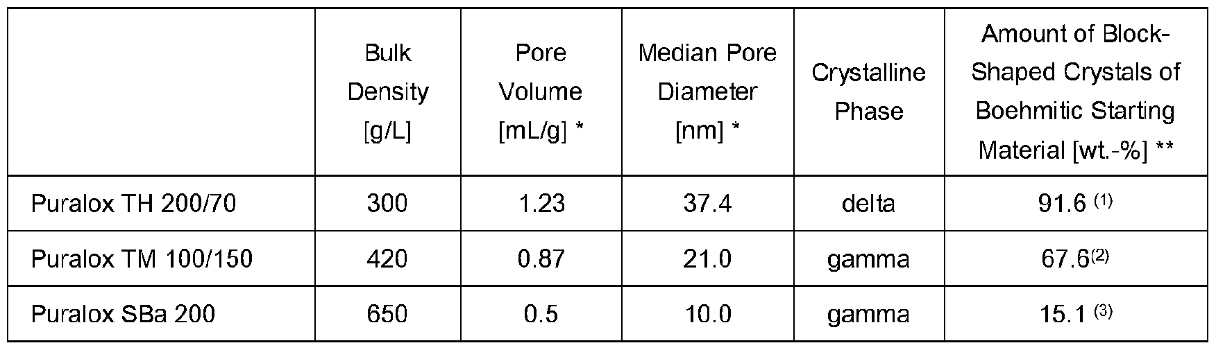
* determined by nitrogen sorption
** calculated by PXRD pattern analysis using DIANNA software; aspect ratio of at most 3.0 <1> the boehmitic starting material of Puralox TH 200/70 is believed to be a material available as Pural TH 200
<2> the boehmitic starting material of Puralox TM 100/150 is believed to be a material available as Pural TM 100 w the boehmitic starting material of Puralox SBa 200 is believed to be a material available as Pural SB1 Example 1 - Preparation of Supports A, B and C
Boehmitic-derived aluminas and inorganic bond materials, as specified in Table 2, were mixed to obtain a powder mixture. Kollidon® VA64 (a vinylpyrrolidone-vinyl acetate copolymer from BASF) was added to the powder mixture. Water was then added to obtain a malleable precursor material. The amounts of all components are shown in Table 2.
The malleable precursor material was mixed to homogeneity via a mix-muller and subsequently extruded using a ram extruder to form shaped bodies. The shaped bodies were in the form of hollow cylinders having an outer diameter of about 10 mm and an inner diameter of about 5 mm. The extrudates were dried at 110 °C for approximately 16 h, followed by heat treatment in a muffle furnace at 600 °C for 2 h and subsequently at 1 ,500 °C for 2 h. Heat treatment was performed in an atmosphere of air.
Table 2

* comparative example
Table 3 shows the physical properties of supports A, B, and C. Figures 1 to 3 show the log differential intrusion and cumulative intrusion relative to the pore size diameter of supports A, B, and C.
Table 3

* comparative example ** determined by mercury porosimetry
*** rPv = ratio of the pore volume contained in pores with a diameter in the range of more than 1 to 10 pm to the pore volume contained in pores with a diameter in the range of 0.1 to 1 pm
It is evident that supports A, and B exhibit advantageously high proportions of pores with a diameter in the range of 0.1 to 1 pm in comparison to supports C. Supports A, and B also exhibit lower rpv values than supports C.
The surface area of supports A and B is significantly larger than that of support C.
Claims
1. A process for producing a porous alpha-alumina catalyst support, comprising i) preparing a precursor material comprising a boehmitic-derived alumina having a pore volume of at least 0.6 mL/g, wherein the boehmitic-derived alumina is obtained by thermal decomposition of a boehmitic starting material and the boehmitic starting material consists predominantly of block-shaped crystals, and optionally an inorganic bond material; ii) forming the precursor material into shaped bodies; iii) calcining the shaped bodies to obtain the porous alpha-alumina catalyst support.
2. The process according to claim 1 , wherein the block-shaped crystals have an aspect ratio of at most 3.0, preferably at most 2.5, wherein the aspect ratio is defined as the ratio of the largest crystal dimension to the smallest crystal dimension.
3. The process according to claim 1 or 2, wherein the boehmitic starting material consists of at least 60 wt.-%, preferably at least 80 wt.-%, of block-shaped crystals, relative to the total weight of crystals constituting the boehmitic starting material.
4. The process according to any one of the preceding claims, wherein the boehmitic starting material comprises boehmite and/or pseudoboehmite, preferably boehmite.
5. The process according to any one of the preceding claims, wherein the precursor material comprises, based on inorganic solids content, at least 50 wt.-%, preferably at least 60 wt.-%, of the boehmitic-derived alumina.
6. The process according to any one of the preceding claims, wherein the boehmitic-derived alumina comprises alpha-alumina, a transition alumina, or mixtures thereof, preferably a transition alumina.
7. The process according to claim 6, wherein the transition alumina comprises at least 50 wt.-% of a transition alumina having an average particle size of 10 to 100 pm, preferably 20 to 50 pm, based on the total weight of transition alumina.
8. The process according to any one of the preceding claims, wherein the boehmitic-derived alumina has a loose bulk density in the range of 50 to 600 g/L, a pore volume of 0.6 to 2.0 mL/g, as determined by nitrogen sorption, and a median pore diameter of at least 15 nm, as determined by nitrogen sorption.
9. The process according to any one of the preceding claims, wherein the boehmitic-derived alumina has a total content of alkali metals of at most 1500 ppm, more preferably at most 600 ppm and most preferably 10 to 200 ppm.
10. The process according to any one of the preceding claims, wherein the precursor material comprises, based on inorganic solids content, 1 to 30 wt.-% of the inorganic bond material.
11. The process according to any one of the preceding claims, wherein the precursor material is formed into shaped bodies via extrusion, tableting, granulation casting, molding, or micro-extrusion, in particular via extrusion or tableting.
12. The process according to any one of the preceding claims, wherein calcining is performed at a temperature of at least 1300 °C, preferably at least 1400 °C, more preferably at least 1500 °C.
13. A shaped catalyst body for producing ethylene oxide by gas-phase oxidation of ethylene, comprising at least 15 wt.-% of silver, relative to the total weight of the catalyst, deposited on a porous alpha-alumina catalyst support obtained in the process according to any one of claims 1 to 12.
14. The shaped catalyst body according to claim 13, comprising 15 to 70 wt.-% of silver, preferably 20 to 60 wt.-% of silver, more preferably 25 to 50 wt.-% or 30 to 50 wt.-% of silver, relative to the total weight of the shaped catalyst body.
15. A process for preparing a shaped catalyst body as defined in claim 13 or 14, comprising a) impregnating a porous alpha-alumina catalyst support obtained in the process according to any one of claims 1 to 11 with a silver impregnation solution, preferably under reduced pressure; and optionally subjecting the impregnated porous alumina support to drying; and b) subjecting the impregnated porous alpha-alumina support to a heat treatment; wherein steps a) and b) are optionally repeated.
16. A process for producing ethylene oxide by gas-phase oxidation of ethylene, comprising reacting ethylene and oxygen in the presence of a shaped catalyst body according to claim 13 or 14.
Priority Applications (1)
| Application Number | Priority Date | Filing Date | Title |
|---|---|---|---|
| US18/011,543 US20230256415A1 (en) | 2020-06-26 | 2021-06-24 | Production of porous alpha-alumina supports from boehmitic derived aluminas |
Applications Claiming Priority (2)
| Application Number | Priority Date | Filing Date | Title |
|---|---|---|---|
| EP20182569.2 | 2020-06-26 | ||
| EP20182569 | 2020-06-26 |
Publications (1)
| Publication Number | Publication Date |
|---|---|
| WO2021260140A1 true WO2021260140A1 (en) | 2021-12-30 |
Family
ID=71451964
Family Applications (1)
| Application Number | Title | Priority Date | Filing Date |
|---|---|---|---|
| PCT/EP2021/067398 WO2021260140A1 (en) | 2020-06-26 | 2021-06-24 | Production of porous alpha-alumina supports from boehmitic derived aluminas |
Country Status (2)
| Country | Link |
|---|---|
| US (1) | US20230256415A1 (en) |
| WO (1) | WO2021260140A1 (en) |
Citations (53)
| Publication number | Priority date | Publication date | Assignee | Title |
|---|---|---|---|---|
| US2411807A (en) | 1945-05-24 | 1946-11-26 | Aluminum Co Of America | Removing sodium from alumina |
| DE2300512A1 (en) | 1972-01-07 | 1973-07-26 | Shell Int Research | NEW SILVER CATALYSTS AND THEIR PRODUCTION AND USE |
| US3859426A (en) | 1972-01-17 | 1975-01-07 | Gte Sylvania Inc | Method of purifying refractory oxides of aluminum and zirconium |
| DE2454972A1 (en) | 1973-12-05 | 1975-06-12 | Ici Ltd | Silver olefin oxidation catalysts - supported on specified carriers and promoted esp. with barium |
| DE2521906A1 (en) | 1974-05-20 | 1975-12-04 | Shell Int Research | SILVER CATALYST, METHOD FOR ITS MANUFACTURING AND USES |
| EP0014457A2 (en) | 1979-02-09 | 1980-08-20 | BASF Aktiengesellschaft | Process for preparing and regenerating supported catalysts and their use in the preparation of ethylene oxide |
| US4356312A (en) | 1972-01-07 | 1982-10-26 | Shell Oil Company | Ethylene oxide process |
| EP0082609A1 (en) | 1981-12-14 | 1983-06-29 | Imperial Chemical Industries Plc | Chemical reactor and process |
| EP0085237A1 (en) | 1981-12-30 | 1983-08-10 | Imperial Chemical Industries Plc | Catalysts for the production of alkylene oxides |
| DE3414717A1 (en) | 1984-04-18 | 1985-10-31 | Linde Ag, 6200 Wiesbaden | METHOD AND REACTOR FOR CARRYING OUT EXOTHERMAL CATALYTIC REACTIONS |
| EP0172565A2 (en) | 1984-08-21 | 1986-02-26 | Mitsubishi Petrochemical Co., Ltd. | Silver catalyst for production of ethylene oxide from ethylene, and process for production thereof |
| US4731350A (en) | 1986-04-29 | 1988-03-15 | Shell Oil Company | Ethylene oxide catalyst |
| EP0266015A1 (en) | 1986-10-31 | 1988-05-04 | Shell Internationale Researchmaatschappij B.V. | Ethylene oxide catalyst and process for the catalytic production of ethylene oxide |
| EP0339748A2 (en) | 1988-04-27 | 1989-11-02 | Shell Internationale Researchmaatschappij B.V. | Process for the preparation of ethylene oxide |
| EP0357293A1 (en) | 1988-08-30 | 1990-03-07 | Union Carbide Corporation | Catalysts for the production of ethylene oxide and their preparation processes |
| US4908343A (en) | 1987-02-20 | 1990-03-13 | Union Carbide Chemicals And Plastics Company Inc. | Catalyst composition for oxidation of ethylene to ethylene oxide |
| US4921681A (en) | 1987-07-17 | 1990-05-01 | Scientific Design Company, Inc. | Ethylene oxide reactor |
| US5187140A (en) | 1989-10-18 | 1993-02-16 | Union Carbide Chemicals & Plastics Technology Corporation | Alkylene oxide catalysts containing high silver content |
| US5504053A (en) | 1989-04-18 | 1996-04-02 | Union Carbide Chemicals & Plastics Technology Corporation | Alkylene oxide catalysts having enhanced activity and/or stability |
| US5504052A (en) | 1994-12-02 | 1996-04-02 | Scientific Design Company, Inc. | Silver catalyst preparation |
| EP0716884A2 (en) | 1994-12-15 | 1996-06-19 | Shell Internationale Researchmaatschappij B.V. | Process for preparing ethylene oxide catalysts |
| US6165437A (en) | 1992-06-02 | 2000-12-26 | Sumitomo Chemical Co., Ltd. | α-alumina |
| EP1115486A1 (en) | 1998-09-14 | 2001-07-18 | Shell Internationale Researchmaatschappij B.V. | Process for preparing catalysts with improved catalytic properties |
| US6452027B1 (en) | 2001-09-10 | 2002-09-17 | Scientific Design Company, Inc. | Heat recovery procedure |
| WO2003072246A2 (en) | 2002-02-25 | 2003-09-04 | Shell Internationale Research Maatschappij B.V. | Supported silver catalyst and an epoxidation process using the catalyst |
| WO2003072244A1 (en) | 2002-02-25 | 2003-09-04 | Saint-Gobain Ceramics & Plastics, Inc. | Catalyst carriers |
| WO2003086624A1 (en) | 2002-04-08 | 2003-10-23 | Scientific Design Company, Inc. | Ethylene oxide catalyst |
| WO2004094055A2 (en) | 2003-04-23 | 2004-11-04 | Sd Lizenzverwertungsgesellschaft Mbh & Co. Kg | Ethylene oxide catalyst |
| EP1613428A2 (en) | 2003-04-01 | 2006-01-11 | Shell Oil Company | An olefin epoxidation process and a catalyst for use in the process |
| WO2006102189A1 (en) | 2005-03-22 | 2006-09-28 | Shell Internationale Research Maatschappij B.V. | A reactor system and process for the manufacture of ethylene oxide |
| US20060281631A1 (en) | 2005-06-07 | 2006-12-14 | Gerdes William H | Catalyst carrier and a process for preparing the catalyst carrier |
| WO2006133183A2 (en) | 2005-06-07 | 2006-12-14 | Shell Internationale Research Maatschappij B.V. | A catalyst, a process for preparing the catalyst, and a process for the production of an olefin oxide, a 1,2-diol, a 1,2-diol ether, or an alkanolamine |
| EP1893331A1 (en) | 2005-05-09 | 2008-03-05 | SD Lizenzverwertungsgesellschaft mbH & Co. KG | Calcination in an inert gas in the presence of a small concentration of an oxidizing component |
| WO2008054564A1 (en) | 2006-11-01 | 2008-05-08 | Dow Global Technologies Inc. | Shaped porous bodies of alpha-alumina and methods for the preparation thereof |
| EP1927398A1 (en) | 2006-09-29 | 2008-06-04 | Nippon Shokubai Co., Ltd. | Catalyst for production of ethylene oxide and method for production of ethylene oxide |
| US20080193369A1 (en) | 2005-08-25 | 2008-08-14 | Barclay David A | Process for Producing High Porosity Boehmite Aluminas |
| US20080305333A1 (en) | 1998-08-14 | 2008-12-11 | Klaus Noweck | Boehmitic Aluminas and High-Temperature Stable, High-Porosity, Pure-Phase Aluminium Oxides Obtained Therefrom |
| WO2009029419A1 (en) | 2007-08-27 | 2009-03-05 | Sd Lizenzverwertungsgesellschaft Gmbh & Co. Kg | Process for production of an olefin oxide |
| US7553795B2 (en) | 2006-03-21 | 2009-06-30 | Sd Lizenzverwertungsgesellschaft Mbh & Co. Kg | Activation of high selectivity ethylene oxide catalyst |
| WO2010000720A2 (en) | 2008-07-02 | 2010-01-07 | Basf Se | Method for producing a geometric oxidic molded body |
| US20120108832A1 (en) * | 2010-11-02 | 2012-05-03 | Jianshe Chen | alumina support, a process for preparing the support, a silver catalyst prepared from the support, and use thereof |
| WO2012140614A1 (en) | 2011-04-14 | 2012-10-18 | Basf Se | Process for producing catalyst for oxidation of ethylene to ethylene oxide |
| US8378129B2 (en) | 2006-08-08 | 2013-02-19 | Sd Lizenzverwertungsgesellschaft Mbh & Co. Kg | Two-stage calcination for catalyst production |
| US8546297B2 (en) | 2010-05-17 | 2013-10-01 | Scientific Design Company, Inc. | Method for preparing an epoxidation catalyst |
| US20140187417A1 (en) | 2012-12-31 | 2014-07-03 | Scientific Design Company, Inc. | Calcination process for producing an improved ethylene oxide catalyst |
| WO2014105770A1 (en) | 2012-12-31 | 2014-07-03 | Scientific Design Company, Inc. | Start-up process for high selectivity ethylene oxide catalysts |
| WO2015095508A1 (en) | 2013-12-19 | 2015-06-25 | Scientific Design Company, Inc. | High-concentration silver solutions for ethylene oxide catalyst preparation |
| WO2019039930A1 (en) | 2017-08-23 | 2019-02-28 | Instituto Mexicano Del Petróleo | Non-destructive method for removing metals, metal ions and metal oxides from alumina-based materials |
| CN109499558A (en) * | 2017-09-15 | 2019-03-22 | 中国石油化工股份有限公司 | A kind of alpha-alumina supports, silver catalyst and olefin epoxidation process |
| WO2019072597A1 (en) | 2017-10-09 | 2019-04-18 | Basf Se | Process for producing catalyst shaped bodies by microextrusion |
| WO2019154863A1 (en) | 2018-02-07 | 2019-08-15 | Basf Se | Method for preparing a silver impregnation solution |
| WO2019219892A1 (en) | 2018-05-18 | 2019-11-21 | Basf Se | Die comprising metal printed parts for the extrusion of moulded bodies |
| EP3639923A1 (en) | 2018-10-15 | 2020-04-22 | Basf Se | Process for producing ethylene oxide by gas-phase oxidation of ethylene |
-
2021
- 2021-06-24 US US18/011,543 patent/US20230256415A1/en active Pending
- 2021-06-24 WO PCT/EP2021/067398 patent/WO2021260140A1/en active Application Filing
Patent Citations (55)
| Publication number | Priority date | Publication date | Assignee | Title |
|---|---|---|---|---|
| US2411807A (en) | 1945-05-24 | 1946-11-26 | Aluminum Co Of America | Removing sodium from alumina |
| DE2300512A1 (en) | 1972-01-07 | 1973-07-26 | Shell Int Research | NEW SILVER CATALYSTS AND THEIR PRODUCTION AND USE |
| US4356312A (en) | 1972-01-07 | 1982-10-26 | Shell Oil Company | Ethylene oxide process |
| US3859426A (en) | 1972-01-17 | 1975-01-07 | Gte Sylvania Inc | Method of purifying refractory oxides of aluminum and zirconium |
| DE2454972A1 (en) | 1973-12-05 | 1975-06-12 | Ici Ltd | Silver olefin oxidation catalysts - supported on specified carriers and promoted esp. with barium |
| DE2521906A1 (en) | 1974-05-20 | 1975-12-04 | Shell Int Research | SILVER CATALYST, METHOD FOR ITS MANUFACTURING AND USES |
| EP0014457A2 (en) | 1979-02-09 | 1980-08-20 | BASF Aktiengesellschaft | Process for preparing and regenerating supported catalysts and their use in the preparation of ethylene oxide |
| EP0082609A1 (en) | 1981-12-14 | 1983-06-29 | Imperial Chemical Industries Plc | Chemical reactor and process |
| EP0085237A1 (en) | 1981-12-30 | 1983-08-10 | Imperial Chemical Industries Plc | Catalysts for the production of alkylene oxides |
| DE3414717A1 (en) | 1984-04-18 | 1985-10-31 | Linde Ag, 6200 Wiesbaden | METHOD AND REACTOR FOR CARRYING OUT EXOTHERMAL CATALYTIC REACTIONS |
| EP0172565A2 (en) | 1984-08-21 | 1986-02-26 | Mitsubishi Petrochemical Co., Ltd. | Silver catalyst for production of ethylene oxide from ethylene, and process for production thereof |
| US4731350A (en) | 1986-04-29 | 1988-03-15 | Shell Oil Company | Ethylene oxide catalyst |
| EP0266015A1 (en) | 1986-10-31 | 1988-05-04 | Shell Internationale Researchmaatschappij B.V. | Ethylene oxide catalyst and process for the catalytic production of ethylene oxide |
| US4908343A (en) | 1987-02-20 | 1990-03-13 | Union Carbide Chemicals And Plastics Company Inc. | Catalyst composition for oxidation of ethylene to ethylene oxide |
| US4921681A (en) | 1987-07-17 | 1990-05-01 | Scientific Design Company, Inc. | Ethylene oxide reactor |
| EP0339748A2 (en) | 1988-04-27 | 1989-11-02 | Shell Internationale Researchmaatschappij B.V. | Process for the preparation of ethylene oxide |
| EP0357293A1 (en) | 1988-08-30 | 1990-03-07 | Union Carbide Corporation | Catalysts for the production of ethylene oxide and their preparation processes |
| US5504053A (en) | 1989-04-18 | 1996-04-02 | Union Carbide Chemicals & Plastics Technology Corporation | Alkylene oxide catalysts having enhanced activity and/or stability |
| US5187140A (en) | 1989-10-18 | 1993-02-16 | Union Carbide Chemicals & Plastics Technology Corporation | Alkylene oxide catalysts containing high silver content |
| US6165437A (en) | 1992-06-02 | 2000-12-26 | Sumitomo Chemical Co., Ltd. | α-alumina |
| US5646087A (en) | 1994-12-02 | 1997-07-08 | Scientific Design Company, Inc. | Promoted silver acatalyst preparation |
| US5504052A (en) | 1994-12-02 | 1996-04-02 | Scientific Design Company, Inc. | Silver catalyst preparation |
| EP0716884A2 (en) | 1994-12-15 | 1996-06-19 | Shell Internationale Researchmaatschappij B.V. | Process for preparing ethylene oxide catalysts |
| US20080305333A1 (en) | 1998-08-14 | 2008-12-11 | Klaus Noweck | Boehmitic Aluminas and High-Temperature Stable, High-Porosity, Pure-Phase Aluminium Oxides Obtained Therefrom |
| EP1115486A1 (en) | 1998-09-14 | 2001-07-18 | Shell Internationale Researchmaatschappij B.V. | Process for preparing catalysts with improved catalytic properties |
| US6452027B1 (en) | 2001-09-10 | 2002-09-17 | Scientific Design Company, Inc. | Heat recovery procedure |
| WO2003072244A1 (en) | 2002-02-25 | 2003-09-04 | Saint-Gobain Ceramics & Plastics, Inc. | Catalyst carriers |
| WO2003072246A2 (en) | 2002-02-25 | 2003-09-04 | Shell Internationale Research Maatschappij B.V. | Supported silver catalyst and an epoxidation process using the catalyst |
| WO2003086624A1 (en) | 2002-04-08 | 2003-10-23 | Scientific Design Company, Inc. | Ethylene oxide catalyst |
| EP1613428A2 (en) | 2003-04-01 | 2006-01-11 | Shell Oil Company | An olefin epoxidation process and a catalyst for use in the process |
| WO2004094055A2 (en) | 2003-04-23 | 2004-11-04 | Sd Lizenzverwertungsgesellschaft Mbh & Co. Kg | Ethylene oxide catalyst |
| WO2006102189A1 (en) | 2005-03-22 | 2006-09-28 | Shell Internationale Research Maatschappij B.V. | A reactor system and process for the manufacture of ethylene oxide |
| EP1893331A1 (en) | 2005-05-09 | 2008-03-05 | SD Lizenzverwertungsgesellschaft mbH & Co. KG | Calcination in an inert gas in the presence of a small concentration of an oxidizing component |
| US20060281631A1 (en) | 2005-06-07 | 2006-12-14 | Gerdes William H | Catalyst carrier and a process for preparing the catalyst carrier |
| WO2006133183A2 (en) | 2005-06-07 | 2006-12-14 | Shell Internationale Research Maatschappij B.V. | A catalyst, a process for preparing the catalyst, and a process for the production of an olefin oxide, a 1,2-diol, a 1,2-diol ether, or an alkanolamine |
| EP2617489A1 (en) | 2005-06-07 | 2013-07-24 | Saint-Gobain Ceramics & Plastics Inc. | A catalyst carrier and a process for preparing the catalyst carrier |
| US20080193369A1 (en) | 2005-08-25 | 2008-08-14 | Barclay David A | Process for Producing High Porosity Boehmite Aluminas |
| US7553795B2 (en) | 2006-03-21 | 2009-06-30 | Sd Lizenzverwertungsgesellschaft Mbh & Co. Kg | Activation of high selectivity ethylene oxide catalyst |
| US8378129B2 (en) | 2006-08-08 | 2013-02-19 | Sd Lizenzverwertungsgesellschaft Mbh & Co. Kg | Two-stage calcination for catalyst production |
| EP1927398A1 (en) | 2006-09-29 | 2008-06-04 | Nippon Shokubai Co., Ltd. | Catalyst for production of ethylene oxide and method for production of ethylene oxide |
| WO2008054564A1 (en) | 2006-11-01 | 2008-05-08 | Dow Global Technologies Inc. | Shaped porous bodies of alpha-alumina and methods for the preparation thereof |
| WO2009029419A1 (en) | 2007-08-27 | 2009-03-05 | Sd Lizenzverwertungsgesellschaft Gmbh & Co. Kg | Process for production of an olefin oxide |
| WO2010000720A2 (en) | 2008-07-02 | 2010-01-07 | Basf Se | Method for producing a geometric oxidic molded body |
| US8546297B2 (en) | 2010-05-17 | 2013-10-01 | Scientific Design Company, Inc. | Method for preparing an epoxidation catalyst |
| US20120108832A1 (en) * | 2010-11-02 | 2012-05-03 | Jianshe Chen | alumina support, a process for preparing the support, a silver catalyst prepared from the support, and use thereof |
| WO2012140614A1 (en) | 2011-04-14 | 2012-10-18 | Basf Se | Process for producing catalyst for oxidation of ethylene to ethylene oxide |
| US20140187417A1 (en) | 2012-12-31 | 2014-07-03 | Scientific Design Company, Inc. | Calcination process for producing an improved ethylene oxide catalyst |
| WO2014105770A1 (en) | 2012-12-31 | 2014-07-03 | Scientific Design Company, Inc. | Start-up process for high selectivity ethylene oxide catalysts |
| WO2015095508A1 (en) | 2013-12-19 | 2015-06-25 | Scientific Design Company, Inc. | High-concentration silver solutions for ethylene oxide catalyst preparation |
| WO2019039930A1 (en) | 2017-08-23 | 2019-02-28 | Instituto Mexicano Del Petróleo | Non-destructive method for removing metals, metal ions and metal oxides from alumina-based materials |
| CN109499558A (en) * | 2017-09-15 | 2019-03-22 | 中国石油化工股份有限公司 | A kind of alpha-alumina supports, silver catalyst and olefin epoxidation process |
| WO2019072597A1 (en) | 2017-10-09 | 2019-04-18 | Basf Se | Process for producing catalyst shaped bodies by microextrusion |
| WO2019154863A1 (en) | 2018-02-07 | 2019-08-15 | Basf Se | Method for preparing a silver impregnation solution |
| WO2019219892A1 (en) | 2018-05-18 | 2019-11-21 | Basf Se | Die comprising metal printed parts for the extrusion of moulded bodies |
| EP3639923A1 (en) | 2018-10-15 | 2020-04-22 | Basf Se | Process for producing ethylene oxide by gas-phase oxidation of ethylene |
Non-Patent Citations (7)
| Title |
|---|
| "Ullmann's Encyclopedia of Industrial Chemistry", vol. A-10, 1987, VCH-VERLAGSGESELLSCHAFT, pages: 117 - 135 |
| BUSCA, CATALYSIS TODAY, vol. 226, 2014, pages 2 - 13 |
| CHEN ET AL., J. SOLID STATE CHEM., vol. 265, 2018, pages 237 - 243 |
| DE SOUZA SANTOS ET AL., MATERIALS RESEARCH, vol. 12, no. 4, 2009, pages 437 - 445 |
| GUZMÁN-CASTILLO ET AL., J. PHYS. CHEM. B, vol. 105, 2001, pages 2099 - 2106 |
| H. GIESCHE: "Mercury Porosimetry: A General (Practical) Overview", PART. PART. SYST. CHARACT., vol. 23, 2006, pages 9 - 19, XP055036551, DOI: 10.1002/ppsc.200601009 |
| YATSENKOTSYBULYA, ZEITSCHRIFT FUR KRISTALLOGRAPHIE, vol. 233, 2018, pages 61 - 66 |
Also Published As
| Publication number | Publication date |
|---|---|
| US20230256415A1 (en) | 2023-08-17 |
Similar Documents
| Publication | Publication Date | Title |
|---|---|---|
| AU680299B2 (en) | Epoxidation catalyst and process | |
| KR100591031B1 (en) | Catalyst carriers | |
| CA2667980C (en) | Shaped porous bodies of alpha-alumina and methods for the preparation thereof | |
| AU711973B2 (en) | Epoxidation catalyst and process | |
| US5733842A (en) | Method of making porous catalyst carrier without the addition of pore forming agents | |
| CA2381411C (en) | Micro-crystalline boehmites containing additives and shaped particles and catalyst compositions comprising such micro-crystalline boehmite | |
| JPH0698267B2 (en) | Method for treating industrial gas containing sulfur compounds | |
| JPH074526B2 (en) | Catalyst for treating industrial exhaust gas containing sulfur compounds | |
| EP1262236B1 (en) | Method for producing alpha-alumina formed body | |
| US20230256414A1 (en) | Process for producing a porous alpha-alumina catalyst support | |
| RU2112595C1 (en) | Catalyst for treating gases containing sulfur compounds and gas treatment method | |
| EP3574993A1 (en) | Method for producing transition alumina catalyst monoliths | |
| US20230256415A1 (en) | Production of porous alpha-alumina supports from boehmitic derived aluminas | |
| US20230234030A1 (en) | Tableted alpha-alumina catalyst support | |
| US20230256420A1 (en) | Shaped catalyst body for the production of ethylene oxide | |
| JP2001226172A (en) | Alumina-based formed body | |
| CN117042873A (en) | Catalytic element with regular cellular structure for heterogeneous reactions | |
| WO2022268348A1 (en) | High purity tableted alpha-alumina catalyst support | |
| WO2024079247A1 (en) | Epoxidation catalyst |
Legal Events
| Date | Code | Title | Description |
|---|---|---|---|
| 121 | Ep: the epo has been informed by wipo that ep was designated in this application |
Ref document number: 21735299 Country of ref document: EP Kind code of ref document: A1 |
|
| NENP | Non-entry into the national phase |
Ref country code: DE |
|
| 122 | Ep: pct application non-entry in european phase |
Ref document number: 21735299 Country of ref document: EP Kind code of ref document: A1 |