WO2021256074A1 - Defibrillation device and method - Google Patents
Defibrillation device and method Download PDFInfo
- Publication number
- WO2021256074A1 WO2021256074A1 PCT/JP2021/015880 JP2021015880W WO2021256074A1 WO 2021256074 A1 WO2021256074 A1 WO 2021256074A1 JP 2021015880 W JP2021015880 W JP 2021015880W WO 2021256074 A1 WO2021256074 A1 WO 2021256074A1
- Authority
- WO
- WIPO (PCT)
- Prior art keywords
- patient
- unit
- electric shock
- oxygen saturation
- toi
- Prior art date
Links
Images


Classifications
-
- A—HUMAN NECESSITIES
- A61—MEDICAL OR VETERINARY SCIENCE; HYGIENE
- A61B—DIAGNOSIS; SURGERY; IDENTIFICATION
- A61B5/00—Measuring for diagnostic purposes; Identification of persons
- A61B5/24—Detecting, measuring or recording bioelectric or biomagnetic signals of the body or parts thereof
- A61B5/316—Modalities, i.e. specific diagnostic methods
- A61B5/318—Heart-related electrical modalities, e.g. electrocardiography [ECG]
-
- A—HUMAN NECESSITIES
- A61—MEDICAL OR VETERINARY SCIENCE; HYGIENE
- A61N—ELECTROTHERAPY; MAGNETOTHERAPY; RADIATION THERAPY; ULTRASOUND THERAPY
- A61N1/00—Electrotherapy; Circuits therefor
- A61N1/18—Applying electric currents by contact electrodes
- A61N1/32—Applying electric currents by contact electrodes alternating or intermittent currents
- A61N1/38—Applying electric currents by contact electrodes alternating or intermittent currents for producing shock effects
- A61N1/39—Heart defibrillators
- A61N1/3904—External heart defibrillators [EHD]
-
- A—HUMAN NECESSITIES
- A61—MEDICAL OR VETERINARY SCIENCE; HYGIENE
- A61B—DIAGNOSIS; SURGERY; IDENTIFICATION
- A61B5/00—Measuring for diagnostic purposes; Identification of persons
- A61B5/145—Measuring characteristics of blood in vivo, e.g. gas concentration, pH value; Measuring characteristics of body fluids or tissues, e.g. interstitial fluid, cerebral tissue
- A61B5/1455—Measuring characteristics of blood in vivo, e.g. gas concentration, pH value; Measuring characteristics of body fluids or tissues, e.g. interstitial fluid, cerebral tissue using optical sensors, e.g. spectral photometrical oximeters
- A61B5/14551—Measuring characteristics of blood in vivo, e.g. gas concentration, pH value; Measuring characteristics of body fluids or tissues, e.g. interstitial fluid, cerebral tissue using optical sensors, e.g. spectral photometrical oximeters for measuring blood gases
-
- A—HUMAN NECESSITIES
- A61—MEDICAL OR VETERINARY SCIENCE; HYGIENE
- A61B—DIAGNOSIS; SURGERY; IDENTIFICATION
- A61B5/00—Measuring for diagnostic purposes; Identification of persons
- A61B5/24—Detecting, measuring or recording bioelectric or biomagnetic signals of the body or parts thereof
- A61B5/316—Modalities, i.e. specific diagnostic methods
- A61B5/318—Heart-related electrical modalities, e.g. electrocardiography [ECG]
- A61B5/346—Analysis of electrocardiograms
- A61B5/349—Detecting specific parameters of the electrocardiograph cycle
-
- A—HUMAN NECESSITIES
- A61—MEDICAL OR VETERINARY SCIENCE; HYGIENE
- A61N—ELECTROTHERAPY; MAGNETOTHERAPY; RADIATION THERAPY; ULTRASOUND THERAPY
- A61N1/00—Electrotherapy; Circuits therefor
- A61N1/18—Applying electric currents by contact electrodes
- A61N1/32—Applying electric currents by contact electrodes alternating or intermittent currents
- A61N1/38—Applying electric currents by contact electrodes alternating or intermittent currents for producing shock effects
- A61N1/39—Heart defibrillators
- A61N1/3925—Monitoring; Protecting
Definitions
- the display monitor 10 may inform the rescuer that chest compressions on the patient should be continued when the numerical value related to TOI does not exceed the threshold value.
- the rescuer may also be informed that chest compressions on the patient should be continued in signaling step ST7 if the value for TOI does not exceed the threshold. This can encourage the rescuer to continue chest compressions when the TOI does not exceed the threshold and suppress the decline in the TOI.
Abstract
A defibrillator 1 constitutes a device for defibrillation and comprises: an oxygen saturation (TOI) measurement unit 11 that acquires a numerical value pertaining to the oxygen saturation of a patient; an electrocardiogram (ECG) measurement unit 6 that measures an electrocardiogram of the patient in order to determine whether it is necessary to electrically shock the patient; and a control unit 12 that initiates the measurement of the electrocardiogram of the patient by the electrocardiogram measurement unit 6 on the condition that the numerical value acquired by the oxygen saturation measurement unit 11 exceeds a threshold value. As a result of this feature, a defibrillation device and method that can increase the success rate of defibrillation through electric shock, and that can reduce the number of occurrences of electrocardiographic analysis and electric shock, are realized.
Description
本開示は、除細動のための装置及び方法に関するものである。
This disclosure relates to devices and methods for defibrillation.
特許文献1には、患者に心肺蘇生(Cardio Pulmonary Resuscitation:CPR)を施す際に救助者を補助するための装置が開示されている。この装置は、患者の脈拍数を測定する脈拍センサ、及び血中の酸素量を測定するSpO2センサのうち少なくとも一つのセンサと、前記センサの出力を処理し、現在行われているCPRを改善するために救助者が行うべき一つ以上の行動を判断する電子機器と、前記一つ以上の行動を救助者に伝達する喚起装置と、を備える。
Patent Document 1 discloses a device for assisting a rescuer in performing cardio Pulmonary Resuscitation (CPR) to a patient. This device processes at least one of the pulse sensor that measures the patient's pulse rate and the SpO 2 sensor that measures the amount of oxygen in the blood, and the output of the sensor to improve the current CPR. It is provided with an electronic device that determines one or more actions that the rescuer should perform in order to do so, and an arousing device that transmits the one or more actions to the rescuer.
心肺蘇生の際には、患者の心室細動(Ventricular Fibrillation:VF)などの不整脈を除去するために、電気ショックが与えられる。この電気ショックを与える前には、患者の不整脈の状態を確認するために、心電図解析が行われる。例えば自動体外式除細動器(Automated External Defibrillator:AED)は、心電図解析から電気ショックまでの一連の動作を自動的に行う。
During cardiopulmonary resuscitation, an electric shock is given to eliminate arrhythmias such as ventricular fibrillation (VF) of the patient. Prior to giving this electric shock, an electrocardiogram analysis is performed to confirm the patient's arrhythmia status. For example, an Automated External Defibrillator (AED) automatically performs a series of operations from electrocardiogram analysis to electric shock.
しかしながら、心電図解析、及び電気ショックのための充電には或る程度の時間を要し、また心電図解析及び充電を行っている間は胸骨圧迫を行うことができない。故に、胸骨圧迫によって一旦上昇した血中酸素濃度は、心電図解析及び充電を行っている間に徐々に下降する。したがって、心電図解析及び電気ショックを繰り返すと、胸骨圧迫により上昇した血中酸素濃度がその都度下降することとなる。その結果、血中酸素濃度の上昇が緩慢となり、心肺蘇生に時間がかかってしまう。
However, it takes a certain amount of time for electrocardiogram analysis and charging for electric shock, and chest compressions cannot be performed during electrocardiogram analysis and charging. Therefore, the blood oxygen concentration once increased by chest compressions gradually decreases during ECG analysis and charging. Therefore, when the electrocardiogram analysis and the electric shock are repeated, the blood oxygen concentration increased by chest compressions decreases each time. As a result, the increase in blood oxygen concentration becomes slow, and cardiopulmonary resuscitation takes time.
実施形態は、電気ショックによる除細動の成功率を高め、心電図解析及び電気ショックの回数を減らすことができる除細動のための装置及び方法を提供することを目的とする。
The embodiment aims to provide a device and method for defibrillation that can increase the success rate of defibrillation by electric shock and reduce the number of electrocardiographic analysis and electric shock.
実施形態は、除細動のための装置である。除細動のための装置は、患者の酸素飽和度に関する数値を取得する酸素飽和度測定部と、患者への電気ショックの要否を判断するために患者の心電図を測定する心電図測定部と、酸素飽和度測定部において取得した数値がしきい値を超えていることを条件として、心電図測定部における患者の心電図の測定を開始させる制御部と、を備える。
The embodiment is a device for defibrillation. The device for defibrillation includes an oxygen saturation measuring unit that acquires numerical values related to the patient's oxygen saturation, an electrocardiogram measuring unit that measures the patient's electrocardiogram to determine the necessity of electric shock to the patient, and an electrocardiogram measuring unit. It is provided with a control unit for starting the measurement of the patient's electrocardiogram in the electrocardiogram measurement unit on condition that the numerical value acquired in the oxygen saturation measurement unit exceeds the threshold value.
実施形態は、除細動のための方法である。除細動のための方法は、患者の酸素飽和度に関する数値の取得を開始するステップと、酸素飽和度に関する数値がしきい値を超えていることを条件として患者の心電図を測定するステップと、心電図の測定結果に基づいて患者への電気ショックの要否を判断するステップと、を含む。
The embodiment is a method for defibrillation. Defibrillation methods include the step of initiating the acquisition of a patient's oxygen saturation value and the step of measuring the patient's electrocardiogram provided that the oxygen saturation value exceeds the threshold. Includes a step of determining the need for an electric shock to the patient based on the ECG measurement results.
これらの装置及び方法では、患者の酸素飽和度がしきい値を超えていることを条件として、電気ショックの要否を判断するための心電図の測定を行う。後述するように、本発明者らは、患者の酸素飽和度が電気ショックによる除細動の成否に影響することを見出した。
With these devices and methods, the electrocardiogram is measured to determine the necessity of electric shock, provided that the oxygen saturation of the patient exceeds the threshold value. As will be described later, the present inventors have found that the oxygen saturation of a patient affects the success or failure of defibrillation due to electric shock.
患者の酸素飽和度が或るしきい値を超えると、電気ショックによる除細動の成功率が有意に上昇する。したがって、酸素飽和度がしきい値を超えている場合には、心電図解析および電気ショックを行い、酸素飽和度がしきい値を超えない場合には、心電図解析および電気ショックを行わずに胸骨圧迫を優先する。これにより、電気ショックによる除細動の成功率を高め、心電図解析及び電気ショックの回数を減らすことができる。
When the patient's oxygen saturation exceeds a certain threshold, the success rate of defibrillation due to electric shock increases significantly. Therefore, if oxygen saturation exceeds the threshold, perform ECG analysis and electrical shock, and if oxygen saturation does not exceed the threshold, perform chest compressions without ECG analysis and electrical shock. Give priority to. This can increase the success rate of defibrillation due to electric shock and reduce the number of electrocardiographic analysis and electric shock.
実施形態によれば、電気ショックによる除細動の成功率を高め、心電図解析及び電気ショックの回数を減らすことができる除細動のための装置及び方法を提供できる。
According to the embodiment, it is possible to provide a device and a method for defibrillation that can increase the success rate of defibrillation by electric shock and reduce the number of electrocardiogram analysis and electric shock.
以下、添付図面を参照しながら、除細動のための装置及び方法の実施の形態を詳細に説明する。なお、図面の説明において同一の要素には同一の符号を付し、重複する説明を省略する。本発明は、これらの例示に限定されるものではない。
Hereinafter, embodiments of the device and method for defibrillation will be described in detail with reference to the attached drawings. In the description of the drawings, the same elements are designated by the same reference numerals, and duplicate description will be omitted. The present invention is not limited to these examples.
図1は、一実施形態に係る除細動器1の構成を示す機能ブロック図である。除細動器1は、患者の心室頻拍(Ventricular Tachycardia:VT)、心室細動(VF)、心房細動(Atrial Fibrillation:AF)などに対して除細動を行う装置である。ここでいう除細動とは、電気的刺激によって異常な電気信号経路を遮断し、正常な電気信号経路への改善を促す処置をいう。
FIG. 1 is a functional block diagram showing a configuration of a defibrillator 1 according to an embodiment. The defibrillator 1 is a device that defibrillates a patient's ventricular tachycardia (VT), ventricular fibrillation (VF), atrial fibrillation (AF), and the like. Defibrillation as used herein refers to a procedure in which an abnormal electrical signal path is blocked by an electrical stimulus to promote improvement to a normal electrical signal path.
本実施形態の除細動器1は、本体部2と、NIRSセンサ3と、電極パッド4とを備えている。本体部2は、TOI演算部5と、ECG測定部6と、判定部7と、ECG解析部8と、電気ショック部9と、表示モニタ10と、を有する。
The defibrillator 1 of the present embodiment includes a main body 2, an NIRS sensor 3, and an electrode pad 4. The main body 2 includes a TOI calculation unit 5, an ECG measurement unit 6, a determination unit 7, an ECG analysis unit 8, an electric shock unit 9, and a display monitor 10.
本体部2は、中空の筐体を有し、その筐体内にTOI演算部5、ECG測定部6、判定部7、ECG解析部8、及び電気ショック部9を収容している。表示モニタ10は、筐体の外面に取り付けられ、本体部2の外部から視認可能とされている。NIRSセンサ3及び電極パッド4は、本体部2から延びるケーブルの先端に取り付けられている。
The main body 2 has a hollow housing, and the TOI calculation unit 5, the ECG measurement unit 6, the determination unit 7, the ECG analysis unit 8, and the electric shock unit 9 are housed in the housing. The display monitor 10 is attached to the outer surface of the housing and is visible from the outside of the main body 2. The NIRS sensor 3 and the electrode pad 4 are attached to the tip of a cable extending from the main body 2.
NIRSセンサ3及びTOI演算部5は、本実施形態におけるTOI測定部11を構成している。TOI測定部11は、胸骨圧迫の繰り返しに起因して変動する、患者の体内(例えば頭部)の組織酸素飽和度(Tissue Oxygenation Index:TOI)に関する数値を測定し、その測定結果を表示モニタ10に表示して、胸骨圧迫を行っている者に知らせる。
The NIRS sensor 3 and the TOI calculation unit 5 constitute the TOI measurement unit 11 in the present embodiment. The TOI measuring unit 11 measures a numerical value relating to the tissue oxygen saturation (Tissue Oxygenation Index: TOI) in the patient's body (for example, the head), which fluctuates due to repeated chest compressions, and displays the measurement result on the display monitor 10. Notify those who are performing chest compressions.
具体的には、TOI測定部11は、体表面に装着されたNIRSセンサ3から所定の光入射位置に近赤外光を入射し、体表面における所定の光検出位置から出射される近赤外光の強度を検出する。これにより、TOI測定部11は、酸素化ヘモグロビン(O2Hb)及び脱酸素化ヘモグロビン(HHb)による近赤外光への影響を調べ、これに基づいて酸素化ヘモグロビン(O2Hb)及び脱酸素化ヘモグロビン(HHb)の各濃度を繰り返し算出する。このような方式は、近赤外分光法(Near-Infrared Spectroscopy:NIRS)と呼ばれる。
Specifically, the TOI measurement unit 11 incidents near-infrared light at a predetermined light incident position from the NIRS sensor 3 mounted on the body surface, and emits near-infrared light from the predetermined light detection position on the body surface. Detects light intensity. As a result, the TOI measuring unit 11 investigates the effect of oxygenated hemoglobin (O 2 Hb) and deoxidized hemoglobin (HHb) on near-infrared light, and based on this, oxygenated hemoglobin (O 2 Hb) and deoxidized hemoglobin (O 2 Hb). Each concentration of oxygenated hemoglobin (HHb) is repeatedly calculated. Such a method is called Near-Infrared Spectroscopy (NIRS).
TOIは、血中ヘモグロビンの酸素化度合いを表す数値であって、総ヘモグロビン濃度に対する酸素化ヘモグロビン濃度の割合として算出される。また、本実施形態においてTOIに関する数値とは、TOIそのもの、若しくはTOIと密接な相関を有する数値である。本実施形態のTOI測定部11によって算出される数値は、TOIそのもの、または、或るタイミングでのTOIを基準とする相対的なTOIの時間変化量である。
TOI is a numerical value indicating the degree of oxygenation of hemoglobin in blood, and is calculated as the ratio of the oxygenated hemoglobin concentration to the total hemoglobin concentration. Further, in the present embodiment, the numerical value relating to the TOI is the TOI itself or a numerical value having a close correlation with the TOI. The numerical value calculated by the TOI measuring unit 11 of the present embodiment is the TOI itself or the relative time change amount of the TOI based on the TOI at a certain timing.
図2は、TOI測定部11の具体的構成例を示す図である。NIRSセンサ3は、例えば毛髪の無い前額部や頸動脈付近に、粘着テープや伸縮性のバンド等によって固定される。
FIG. 2 is a diagram showing a specific configuration example of the TOI measuring unit 11. The NIRS sensor 3 is fixed to, for example, a hairless forehead or the vicinity of the carotid artery with an adhesive tape, an elastic band, or the like.
NIRSセンサ3は、光入射部31及び光検出部32を有している。光入射部31と光検出部32とは、互いに間隔をあけて配置され、柔軟な黒色のシリコンゴム製のホルダー33によって実質的に一体化されている。ホルダー33の素材は、シリコンゴムと同等の柔軟性を有する他の素材に置き換えられてもよい。NIRSセンサ3は、ケーブル34を介して本体部2と電気的に接続されている。
The NIRS sensor 3 has a light incident unit 31 and a light detecting unit 32. The light incident unit 31 and the light detection unit 32 are arranged at intervals from each other, and are substantially integrated by a flexible black silicon rubber holder 33. The material of the holder 33 may be replaced with another material having the same flexibility as silicone rubber. The NIRS sensor 3 is electrically connected to the main body 2 via a cable 34.
光入射部31は、本体部2から伝達される制御信号を受けて、所定波長の測定光を出力する。測定光は、患者の体表面の皮層に対してほぼ垂直に入射する。光入射部31は、例えばレーザダイオード、発光ダイオード(LED)、若しくはスーパールミネッセントダイオード(SLD)と、その駆動回路とを有する。測定光の波長は近赤外域に含まれ、一例では735nm、810nm、及び850nmの波長成分を含む。
The light incident unit 31 receives the control signal transmitted from the main body unit 2 and outputs the measurement light having a predetermined wavelength. The measurement light is incident substantially perpendicular to the skin layer on the patient's body surface. The light incident unit 31 includes, for example, a laser diode, a light emitting diode (LED), or a super luminescent diode (SLD), and a drive circuit thereof. The wavelength of the measured light is included in the near-infrared region, and one example includes wavelength components of 735 nm, 810 nm, and 850 nm.
光検出部32は、患者の体内を伝搬して体表面から出射した測定光の強度に応じた検出信号を生成する。光検出部32は、例えば一次元の光センサであり、光入射部31からの距離方向に並べられた複数の光検出器を有している。本構成例の光検出部32は、第1の光検出器321及び第2の光検出器322といった2つの光検出器を有している。
The photodetection unit 32 generates a detection signal according to the intensity of the measurement light propagating in the patient's body and emitted from the body surface. The photodetector 32 is, for example, a one-dimensional photosensor, and has a plurality of photodetectors arranged in a distance direction from the light incident unit 31. The photodetector 32 of this configuration example has two photodetectors such as a first photodetector 321 and a second photodetector 322.
第1の光検出器321は、光入射部31から第1の距離X1だけ離れた位置に設けられている。第2の光検出器322は、光入射部31から第2の距離X2(>X1)だけ離れた位置に設けられている。距離X1は例えば3cmであり、距離X2は例えば4cmである。
The first photodetector 321 is provided at a position separated from the light incident portion 31 by a first distance X1. The second photodetector 322 is provided at a position separated from the light incident portion 31 by a second distance X2 (> X1). The distance X1 is, for example, 3 cm, and the distance X2 is, for example, 4 cm.
第1の光検出器321は、受光した測定光の強度に応じた第1の検出信号を生成する。第2の光検出器322は、受光した測定光の強度に応じた第2の検出信号を生成する。これらの光検出器321,322それぞれは、PD(フォトダイオード)またはAPD(アバランシェフォイトダイオード)といった半導体受光素子と、半導体受光素子から出力される電流を積分し、増幅するプリアンプとを有している。
The first photodetector 321 generates a first detection signal according to the intensity of the received measurement light. The second photodetector 322 generates a second detection signal according to the intensity of the received measurement light. Each of these photodetectors 321 and 322 has a semiconductor light receiving element such as a PD (photodiode) or APD (avalanche foit diode) and a preamplifier that integrates and amplifies the current output from the semiconductor light receiving element. ..
上記の構成において、光検出器321,322それぞれは、微弱な電流を感度良く検出して検出信号を生成し、この検出信号を本体部2へケーブル34を介して伝送することができる。なお、光検出部32は、二次元の光センサであってもよく、例えば、CCDイメージセンサまたはCMOSイメージセンサによって構成されてもよい。
In the above configuration, each of the photodetectors 321, 322 can detect a weak current with high sensitivity to generate a detection signal, and transmit this detection signal to the main body 2 via the cable 34. The photodetector 32 may be a two-dimensional optical sensor, or may be configured by, for example, a CCD image sensor or a CMOS image sensor.
TOI測定部11は、TOI演算部5に加えて、制御部51、モニタ部52、及び指示部53を本体部2の内部に有している。TOI測定部11は、CPUなどの演算回路及びメモリなどの記憶装置を含むコンピュータを備える。TOI演算部5、制御部51、モニタ部52、及び指示部53は、記憶装置に予め格納されたプログラムを演算回路が読み出して実行することにより実現される。
The TOI measurement unit 11 has a control unit 51, a monitor unit 52, and an instruction unit 53 inside the main body unit 2 in addition to the TOI calculation unit 5. The TOI measurement unit 11 includes a computer including an arithmetic circuit such as a CPU and a storage device such as a memory. The TOI calculation unit 5, the control unit 51, the monitor unit 52, and the instruction unit 53 are realized by the calculation circuit reading and executing the program stored in advance in the storage device.
制御部51は、ケーブル34を介してNIRSセンサ3と電気的に接続されている。制御部51は、光入射部31の光出力制御、及び光検出器321,322の光検出制御を行う。すなわち、光入射部31における測定光の出力開始及び終了は、制御部51からの制御信号に基づいて行われる。また、光検出器321,322における測定光の検出開始及び終了は、制御部51からの制御信号に基づいて行われる。
The control unit 51 is electrically connected to the NIRS sensor 3 via a cable 34. The control unit 51 controls the light output of the light incident unit 31 and controls the light detection of the photodetectors 321 and 322. That is, the output start and end of the measurement light in the light incident unit 31 are performed based on the control signal from the control unit 51. Further, the detection start and end of the measurement light in the photodetectors 321 and 322 are performed based on the control signal from the control unit 51.
制御部51は、NIRSセンサ3の装着前から、光検出器321,322に測定光の検出を開始させる(スタンバイモード)。このスタンバイモードは、TOI演算部5がTOIに関する数値の算出を開始するまで継続する。TOI演算部5は、スタンバイモードにおいてはTOIに関する数値の演算を行わない。
The control unit 51 causes the photodetectors 321 and 322 to start detecting the measured light before the NIRS sensor 3 is attached (standby mode). This standby mode continues until the TOI calculation unit 5 starts calculating a numerical value related to the TOI. The TOI calculation unit 5 does not calculate a numerical value related to TOI in the standby mode.
モニタ部52は、TOIに関する数値の算出開始前すなわちスタンバイモードにおいて継続的に生成される光検出部32からの検出信号に基づいて、光検出器321,322に入射する光強度の変化のモニタリング(観察)を行う。モニタ部52は、そのモニタ結果を指示部53へ継続的に出力する。
The monitor unit 52 monitors changes in the light intensity incident on the photodetectors 321 and 322 based on the detection signal from the photodetector unit 32 that is continuously generated before the start of calculation of the numerical value related to the TOI, that is, in the standby mode. Observe). The monitor unit 52 continuously outputs the monitor result to the instruction unit 53.
指示部53は、モニタ部52から得られるモニタ結果に基づいて、TOIに関する数値の算出開始を決定し、算出開始をTOI演算部5に指示する(測定モード)。スタンバイモード開始時における光検出器321,322からの検出信号は、NIRSセンサ3が患者の体表面に取り付けられる前の光強度、すなわち測定環境における環境光(例えば、屋外なら太陽光、屋内なら照明光)の強度を示す。そして、NIRSセンサ3が患者の体表面に装着されると、環境光の強度は、装着前に対して所定の割合(例えば、10%)以下に低下する。
The instruction unit 53 determines the start of calculation of the numerical value related to the TOI based on the monitor result obtained from the monitor unit 52, and instructs the TOI calculation unit 5 to start the calculation (measurement mode). The detection signal from the photodetectors 321 and 322 at the start of the standby mode is the light intensity before the NIRS sensor 3 is attached to the body surface of the patient, that is, the ambient light in the measurement environment (for example, sunlight when outdoors, lighting when indoors). Indicates the intensity of light). Then, when the NIRS sensor 3 is attached to the body surface of the patient, the intensity of the ambient light is reduced to a predetermined ratio (for example, 10%) or less with respect to that before the attachment.
指示部53は、このような強度低下を、光検出器321,322において検出される測定光の強度が所定の範囲内へ変化したか否かによって知ることができる。従って、指示部53は、光検出器321,322において検出される測定光の強度が所定の範囲内にあることを条件として、算出開始を決定するとよい。
The indicator 53 can know such a decrease in intensity by whether or not the intensity of the measured light detected by the photodetectors 321 and 322 has changed within a predetermined range. Therefore, the indicator 53 may determine the start of calculation on condition that the intensity of the measured light detected by the photodetectors 321, 322 is within a predetermined range.
なお、NIRSセンサ3が患者に装着される前であっても、NIRSセンサ3を救助者が扱う際に、光検出部32を手で覆う等により環境光の検出強度が低下する場合がある。従って、指示部53は、光検出部32において検出される測定光の強度が所定の範囲内にある状態が所定の期間(例えば3秒)継続していることを条件として、算出開始を決定してもよい。また、指示部53は、光検出器321,322において検出される測定光の強度変化が所定の幅を超えたことを条件として、算出開始を決定してもよい。
Even before the NIRS sensor 3 is attached to the patient, when the rescuer handles the NIRS sensor 3, the detection intensity of ambient light may decrease by covering the photodetector 32 with a hand or the like. Therefore, the indicator 53 determines to start the calculation on condition that the intensity of the measured light detected by the photodetector 32 is within a predetermined range for a predetermined period (for example, 3 seconds). You may. Further, the indicator 53 may determine the start of calculation on the condition that the change in the intensity of the measured light detected by the photodetectors 321, 322 exceeds a predetermined width.
また、指示部53は、2つの光検出器321,322のうち光源から遠い第2の光検出器322において検出された光強度に基づいて、算出開始を決定してもよい。これにより、入射光強度(環境光強度)の変化をより精度良く捉えることができ、NIRSセンサ3が患者の体表面に装着されるタイミングを的確に検知することができる。
Further, the indicator 53 may determine the start of calculation based on the light intensity detected by the second photodetector 322 far from the light source among the two photodetectors 321 and 322. As a result, changes in the incident light intensity (environmental light intensity) can be captured more accurately, and the timing at which the NIRS sensor 3 is attached to the patient's body surface can be accurately detected.
なお、除細動器1は、TOIに関する数値の算出開始を救助者が指示するための指示入力部54(例えばボタン)を更に備えてもよい。その場合、ボタン押下といった指示入力部54への開始のアクションに基づいて、TOI演算部5がTOIに関する数値の算出を開始する。
The defibrillator 1 may further include an instruction input unit 54 (for example, a button) for the rescuer to instruct the start of calculation of a numerical value related to TOI. In that case, the TOI calculation unit 5 starts the calculation of the numerical value related to the TOI based on the start action to the instruction input unit 54 such as pressing the button.
TOI演算部5は、ケーブル34を介してNIRSセンサ3と電気的に接続される演算処理回路であって、本実施形態における演算部の例である。TOI演算部5は、患者の体内を伝搬した測定光の強度に応じた光検出部32からの検出信号に基づいて、胸骨圧迫の繰り返しに起因して変動する体内のTOIに関する数値を算出する。TOI演算部5は、指示部53からの信号を受けて、TOIに関する数値の算出を開始する。
The TOI calculation unit 5 is an arithmetic processing circuit electrically connected to the NIRS sensor 3 via a cable 34, and is an example of the arithmetic unit in the present embodiment. The TOI calculation unit 5 calculates a numerical value regarding the TOI in the body that fluctuates due to repeated chest compressions, based on a detection signal from the photodetection unit 32 according to the intensity of the measured light propagating in the patient's body. The TOI calculation unit 5 receives a signal from the instruction unit 53 and starts calculating a numerical value related to the TOI.
TOI演算部5は、例えば、SRS法(空間分解分光法)やMBL法(モディファイド・ビア・ランバート法)、PRS法(位相分解分光法)、TRS法(時間分解分光法)、PMS法(位相変調分光法)などの近赤外分光法を用いて、TOIに関する数値を算出する。
The TOI calculation unit 5 includes, for example, the SRS method (spatial resolution spectroscopy), the MBL method (modified via Lambert method), the PRS method (phase resolution spectroscopy), the TRS method (time resolution spectroscopy), and the PMS method (phase). Numerical values related to TOI are calculated using near-infrared spectroscopy such as (modulated spectroscopy).
MBL法は、測定対象中のヘモグロビン濃度(酸素化ヘモグロビン濃度及び脱酸素化ヘモグロビン濃度)により、検出される光量が変化することを利用する。MBL法により、酸素化ヘモグロビン濃度の相対変化量、脱酸素化ヘモグロビン濃度の相対変化量、総ヘモグロビン濃度の相対変化量を求めることができる。MBL法では、光検出器321,322のいずれか一方からの検出信号が用いられる。SRS法は、光入射部31と光検出器321,322との距離に応じて、検出される光量が変化することを利用する。SRS法では、光検出器321,322双方からの検出信号が用いられる。
The MBL method utilizes the fact that the amount of light detected changes depending on the hemoglobin concentration (oxygenated hemoglobin concentration and deoxygenated hemoglobin concentration) in the measurement target. By the MBL method, the relative change amount of the oxygenated hemoglobinometry, the relative change amount of the deoxidized hemoglobinometry, and the relative change amount of the total hemoglobinometry can be obtained. In the MBL method, a detection signal from either one of the photodetectors 321, 322 is used. The SRS method utilizes the fact that the amount of detected light changes according to the distance between the light incident portion 31 and the photodetectors 321 and 322. In the SRS method, detection signals from both photodetectors 321 and 322 are used.
TRS法は、入力されたパルス状の測定光の時間幅が、測定対象に存在するヘモグロビンによって長くなることを利用する。より具体的には、パルス状測定光の時間的な広がりに基づくシミュレーションデータと、検出された光の時間的な広がりとをフィッティングすることにより、ヘモグロビン濃度の絶対値を求める。PRS法は、変調した測定光を測定対象に入射し、入射前の測定光と検出後の測定光との位相差を求めることにより、ヘモグロビン濃度の絶対値を求める。したがって、TRS法またはPRS法によれば、TOIの相対値ではなく絶対値を求めることができる。
The TRS method utilizes the fact that the time width of the input pulsed measurement light is lengthened by the hemoglobin present in the measurement target. More specifically, the absolute value of the hemoglobin concentration is obtained by fitting the simulation data based on the temporal spread of the pulsed measurement light and the temporal spread of the detected light. In the PRS method, the modulated measurement light is incident on the measurement target, and the phase difference between the measurement light before the incident and the measurement light after the detection is obtained to obtain the absolute value of the hemoglobin concentration. Therefore, according to the TRS method or the PRS method, an absolute value can be obtained instead of a relative value of the TOI.
TOIに関する数値の算出周期は0.2秒以下(算出周波数にすると、5Hz以上)であることが好ましい。一般的に、胸骨圧迫の好適な周期は1分間に100回程度(すなわち0.6秒に1回)もしくはそれ以上といわれている。そして、相対変化量の算出周期がその3分の1以下であれば、胸部圧迫に起因する濃度変化を好適に検出することができる。また、所定周波数は、1.66Hz以下であることが好ましい。これにより、1分間に100回程度もしくはそれ以上の胸骨圧迫に起因する濃度変化に関する情報を好適に抽出することができる。
The calculation cycle of the numerical value related to TOI is preferably 0.2 seconds or less (5 Hz or more in the calculated frequency). Generally, it is said that a suitable cycle of chest compressions is about 100 times per minute (that is, once every 0.6 seconds) or more. If the calculation cycle of the relative change amount is one-third or less of that, the concentration change due to chest compression can be suitably detected. Further, the predetermined frequency is preferably 1.66 Hz or less. This makes it possible to suitably extract information on the concentration change caused by chest compressions about 100 times or more per minute.
表示モニタ10は、TOI演算部5から送られたTOIに関する数値の算出結果に関する情報を表示する。救助者は、表示モニタ10の表示を参照しながら、胸骨圧迫が適切に行われているか否かを判断することができる。
The display monitor 10 displays information on the calculation result of the numerical value related to the TOI sent from the TOI calculation unit 5. The rescuer can determine whether or not chest compressions are properly performed while referring to the display on the display monitor 10.
再び図1を参照する。ECG測定部6は、患者への電気ショックの要否を判断するために、患者の心電図(Electrocardiogram:ECG)を測定する。ECG測定部6は、電極パッド4と電気的に接続されており、患者に装着された電極パッド4からの電気信号を時間的に連続して検出することにより、心臓の電気的な活動の様子を時系列で記録する。なお、電極パッド4は正極パッド及び負極パッドを含み、それぞれ胸部付近の異なる位置に装着される。
Refer to Fig. 1 again. The ECG measuring unit 6 measures a patient's electrocardiogram (ECG) in order to determine the necessity of electric shock to the patient. The ECG measuring unit 6 is electrically connected to the electrode pad 4, and by continuously detecting the electric signal from the electrode pad 4 worn on the patient in time, the state of the electrical activity of the heart. Is recorded in chronological order. The electrode pads 4 include a positive electrode pad and a negative electrode pad, and are attached to different positions near the chest.
判定部7及びECG解析部8は、制御部12を構成する。制御部12は、CPUなどの演算回路及びメモリなどの記憶装置を含むコンピュータを備える。判定部7及びECG解析部8は、記憶装置に予め格納されたプログラムを演算回路が読み出して実行することにより実現される。なお、判定部7及びECG解析部8を実現するコンピュータは、TOI測定部11のTOI演算部5等を実現するコンピュータと共通に構成されてもよい。
The determination unit 7 and the ECG analysis unit 8 constitute a control unit 12. The control unit 12 includes a computer including an arithmetic circuit such as a CPU and a storage device such as a memory. The determination unit 7 and the ECG analysis unit 8 are realized by the arithmetic circuit reading and executing the program stored in advance in the storage device. The computer that realizes the determination unit 7 and the ECG analysis unit 8 may be configured in common with the computer that realizes the TOI calculation unit 5 and the like of the TOI measurement unit 11.
判定部7は、TOI測定部11において取得したTOIに関する数値が所定のしきい値を超えているか否かを判定する。判定部7は、TOIに関する数値が所定のしきい値を超えていることを条件として、心電図の測定を開始させるための(或いは、開始可能とする)信号をECG測定部6に与える。
The determination unit 7 determines whether or not the numerical value related to the TOI acquired by the TOI measurement unit 11 exceeds a predetermined threshold value. The determination unit 7 gives the ECG measurement unit 6 a signal for starting (or enabling) the measurement of the electrocardiogram on condition that the numerical value relating to the TOI exceeds a predetermined threshold value.
しきい値は、例えば、TOIの時間的相対変化量に換算して、40%~60%の範囲内に含まれるいずれかの値であってよく、より好適には、TOIの時間的相対変化量に換算して、45%~50%の範囲内に含まれるいずれかの値である。しきい値は、予め記憶装置に記憶されている。
The threshold value may be, for example, any value included in the range of 40% to 60% in terms of the amount of time relative change of TOI, and more preferably, the time relative change of TOI. It is any value included in the range of 45% to 50% in terms of quantity. The threshold value is stored in the storage device in advance.
判定部7は、TOIがしきい値を超えている場合には、心電図の測定を開始したことを救助者に知らせるための表示信号を表示モニタ10に与える。表示モニタ10は、その表示信号を受けると、心電図の測定を開始したことを示す文字、図柄(例えば、「心電図解析を行っています」等)を画面に表示して、救助者に知らせる。
When the TOI exceeds the threshold value, the determination unit 7 gives a display signal to the display monitor 10 to notify the rescuer that the electrocardiogram measurement has started. Upon receiving the display signal, the display monitor 10 displays characters and symbols (for example, "for example," performing electrocardiogram analysis ") indicating that the electrocardiogram measurement has started" on the screen to notify the rescuer.
判定部7は、TOIがしきい値を超えない場合には、患者に対する胸骨圧迫を継続すべきことを救助者に知らせるための表示信号を表示モニタ10に与える。表示モニタ10は、その表示信号を受けると、胸骨圧迫を継続すべきことを示す文字、図柄(例えば、「心臓マッサージを継続してください」等)を画面に表示して、救助者に知らせる。
If the TOI does not exceed the threshold value, the determination unit 7 gives a display signal to the display monitor 10 to inform the rescuer that chest compressions on the patient should be continued. Upon receiving the display signal, the display monitor 10 displays characters and symbols (for example, "Continue cardiac massage") indicating that chest compressions should be continued on the screen to notify the rescuer.
なお、本体部2は、図示しないスピーカを備えてもよい。その場合、判定部7は、TOIがしきい値を超えているときには、心電図の測定を開始したことを救助者に知らせるための信号をスピーカに与え、スピーカは、その信号を受けて、心電図の測定を開始したことを示す音声等を出力してもよい。
The main body 2 may be provided with a speaker (not shown). In that case, the determination unit 7 gives a signal to the speaker to notify the rescuer that the measurement of the electrocardiogram has started when the TOI exceeds the threshold value, and the speaker receives the signal and receives the signal of the electrocardiogram. A voice or the like indicating that the measurement has started may be output.
また、判定部7は、TOIがしきい値を超えないときには、患者に対する胸骨圧迫を継続すべきことを救助者に知らせるための信号をスピーカに与え、スピーカは、その信号を受けて、胸骨圧迫を継続すべきことを示す音声等を出力してもよい。表示モニタ10及びスピーカは、本実施形態における情報伝達部の例である。
Further, the determination unit 7 gives a signal to the speaker to inform the rescuer that the chest compression should be continued for the patient when the TOI does not exceed the threshold value, and the speaker receives the signal and performs chest compression. You may output a voice or the like indicating that the above should be continued. The display monitor 10 and the speaker are examples of the information transmission unit in the present embodiment.
ECG解析部8は、心電図の測定結果をECG測定部6から取得する。ECG解析部8は、心電図を解析し、患者への電気ショックの要否を判断する。ECG解析部8は、電気ショックが不要であると判断すると、電気ショックが不要であることを救助者に知らせるための表示信号を表示モニタ10に与える。表示モニタ10は、その表示信号を受けると、胸骨圧迫を継続すべきことを示す文字、記号等を画面に表示して、救助者に知らせる。
The ECG analysis unit 8 acquires the measurement result of the electrocardiogram from the ECG measurement unit 6. The ECG analysis unit 8 analyzes the electrocardiogram and determines the necessity of electric shock to the patient. When the ECG analysis unit 8 determines that the electric shock is unnecessary, the ECG analysis unit 8 gives the display monitor 10 a display signal for notifying the rescuer that the electric shock is unnecessary. Upon receiving the display signal, the display monitor 10 displays characters, symbols, etc. indicating that chest compressions should be continued on the screen to notify the rescuer.
なお、本体部2がスピーカを備える場合、ECG解析部8は、電気ショックが不要であるときには、患者に対する胸骨圧迫を継続すべきことを救助者に知らせるための信号をスピーカに与え、スピーカは、その信号を受けて、胸骨圧迫を継続すべきことを示す音声等を出力してもよい。
When the main body 2 is provided with a speaker, the ECG analysis unit 8 gives a signal to the rescuer to inform the rescuer that chest compressions to the patient should be continued when the electric shock is not required, and the speaker is used. In response to the signal, a speaker or the like indicating that chest compressions should be continued may be output.
また、ECG解析部8は、電気ショックが必要であると判断すると、電気ショックを開始させるための信号を電気ショック部9に与える。電気ショック部9は、ECG解析部8から信号を受けると、電気ショックのための電気エネルギを電極パッド4から出力する。なお、電気ショックに用いられる電極パッドは、ECG測定に用いられる電極パッドと共通であってもよく、ECG測定に用いられる電極パッドとは別個に設けられてもよい。
Further, when the ECG analysis unit 8 determines that an electric shock is necessary, it gives a signal for initiating the electric shock to the electric shock unit 9. When the electric shock unit 9 receives a signal from the ECG analysis unit 8, the electric shock unit 9 outputs electric energy for the electric shock from the electrode pad 4. The electrode pad used for the electric shock may be common to the electrode pad used for the ECG measurement, or may be provided separately from the electrode pad used for the ECG measurement.
続いて、除細動器1の作動方法とともに、本実施形態による除細動のための方法について説明する。図3は、除細動器1の作動方法及び除細動のための方法を示すフローチャートである。
Subsequently, the operation method of the defibrillator 1 and the method for defibrillation according to the present embodiment will be described. FIG. 3 is a flowchart showing a method of operating the defibrillator 1 and a method for defibrillation.
まず、救助者は、患者の反応がないこと及び呼吸が無いことを確認した後、胸骨圧迫を開始する(ステップST1)。次に、救助者は、除細動器1のNIRSセンサ3及び電極パッド4を患者に装着する(ステップST2)。このとき、モニタ部52がNIRSセンサ3の装着を検知し、TOI測定部11が、TOIに関する数値の取得を開始する(ステップST3)。
First, the rescuer starts chest compressions after confirming that the patient has no reaction and no breathing (step ST1). Next, the rescuer attaches the NIRS sensor 3 and the electrode pad 4 of the defibrillator 1 to the patient (step ST2). At this time, the monitor unit 52 detects that the NIRS sensor 3 is attached, and the TOI measuring unit 11 starts acquiring a numerical value related to the TOI (step ST3).
具体的には、光入射部31が、患者の体内への測定光の入射を開始する(光入射ステップST31)。また、光検出部32が、患者の体内を伝搬した測定光の検出を開始して、測定光の強度に応じた検出信号を生成し始める(光検出ステップST32)。そして、TOI演算部5は、その検出信号に基づいて、TOIに関する数値の算出を開始する(演算ステップST33)。
Specifically, the light incident unit 31 starts incident of the measured light into the patient's body (light incident step ST31). Further, the photodetection unit 32 starts detecting the measurement light propagating in the patient's body and starts to generate a detection signal according to the intensity of the measurement light (light detection step ST32). Then, the TOI calculation unit 5 starts calculating a numerical value related to the TOI based on the detection signal (calculation step ST33).
また、TOI演算部5は、指示入力部54からの入力(例えばボタン押下)による開始のアクションにより、TOIに関する数値の算出を開始してもよい。こうしてTOI測定部11がTOIに関する数値を継続して測定している状況において、救助者は胸骨圧迫を継続する(ステップST4)。
Further, the TOI calculation unit 5 may start the calculation of the numerical value related to the TOI by the action of starting by the input from the instruction input unit 54 (for example, pressing a button). In this situation, the rescuer continues chest compressions in the situation where the TOI measuring unit 11 continuously measures the numerical value related to TOI (step ST4).
電気ショックを行う為の操作入力を救助者が行うと、判定部7は、TOIに関する数値がしきい値を超えているか否かを判定する(ステップST5)。そして、TOIに関する数値がしきい値を超えている場合(ステップST5:YES)、ECG測定部6が心電図の測定を開始する(ステップST6)。
When the rescuer inputs an operation for performing an electric shock, the determination unit 7 determines whether or not the numerical value related to the TOI exceeds the threshold value (step ST5). Then, when the numerical value related to TOI exceeds the threshold value (step ST5: YES), the ECG measuring unit 6 starts the electrocardiogram measurement (step ST6).
また、TOIに関する数値がしきい値を超えていない場合(ステップST5:NO)、患者に対する胸骨圧迫を継続すべきことを、表示モニタ10における表示及びスピーカの音声を通じて救助者に知らせる(情報伝達ステップST7)。その後、ステップST4に戻り、ステップST4及びST5を繰り返す。しきい値は、前述したように、TOIに換算して、40%~60%の範囲内に含まれるいずれかの値であってよく、より好適には、TOIに換算して、45%~50%の範囲内に含まれるいずれかの値である。
In addition, when the numerical value related to TOI does not exceed the threshold value (step ST5: NO), the rescuer is informed through the display on the display monitor 10 and the voice of the speaker that the chest compression on the patient should be continued (information transmission step). ST7). After that, the process returns to step ST4, and steps ST4 and ST5 are repeated. As described above, the threshold value may be any value included in the range of 40% to 60% in terms of TOI, and more preferably 45% to 45% in terms of TOI. Any value within the range of 50%.
ステップST6において心電図を測定したのち、ECG解析部8が心電図を解析して、電気ショックの要否を判断する(ステップST8)。電気ショックが必要と判断された場合(ステップST8:YES)、電気ショック部9が電極パッド4から電気ショックのための電気エネルギを出力する(電気ショックステップST9)。また、電気ショックが不要と判断された場合(ステップST8:NO)、ステップST4に戻り、ステップST4~ST8を繰り返す。
After measuring the electrocardiogram in step ST6, the ECG analysis unit 8 analyzes the electrocardiogram and determines the necessity of electric shock (step ST8). When it is determined that an electric shock is necessary (step ST8: YES), the electric shock unit 9 outputs electric energy for the electric shock from the electrode pad 4 (electric shock step ST9). If it is determined that the electric shock is unnecessary (step ST8: NO), the process returns to step ST4 and steps ST4 to ST8 are repeated.
ステップST9において電気ショックを行ったのち、救助者は、患者の心拍が再開したか否かを判断する(ステップST10)。患者の心拍が再開していない場合(ステップST10:NO)、ステップST4に戻り、ステップST4~ST10を繰り返す。患者の心拍が再開した場合(ステップST10:YES)、心肺蘇生に関する処置を終了する。
After performing the electric shock in step ST9, the rescuer determines whether or not the patient's heartbeat has resumed (step ST10). If the patient's heartbeat has not resumed (step ST10: NO), the patient returns to step ST4 and repeats steps ST4 to ST10. When the patient's heartbeat resumes (step ST10: YES), the procedure for cardiopulmonary resuscitation is terminated.
以上に説明した本実施形態の除細動器1及び除細動のための方法によって得られる効果について説明する。
The effects obtained by the defibrillator 1 and the method for defibrillation of the present embodiment described above will be described.
前述したように、心肺蘇生の際には、患者の心室細動(VF)などの不整脈を除去するために、電気ショックが与えられる。この電気ショックを与える前には、患者の不整脈の状態を確認するために、心電図解析が行われる。
As mentioned above, during cardiopulmonary resuscitation, an electric shock is given to eliminate arrhythmias such as ventricular fibrillation (VF) in the patient. Prior to giving this electric shock, an electrocardiogram analysis is performed to confirm the patient's arrhythmia status.
しかしながら、心電図解析、及び電気ショックのための充電には或る程度の時間を要し、また心電図解析及び充電を行っている間は、胸骨圧迫を行うことができない。故に、胸骨圧迫によって一旦上昇した血中酸素濃度は、心電図解析及び充電を行っている間に徐々に下降する。したがって、心電図解析及び電気ショックを繰り返すと、胸骨圧迫により上昇した血中酸素濃度がその都度下降することとなる。
However, it takes a certain amount of time for electrocardiogram analysis and charging for electric shock, and chest compressions cannot be performed during electrocardiogram analysis and charging. Therefore, the blood oxygen concentration once increased by chest compressions gradually decreases during ECG analysis and charging. Therefore, when the electrocardiogram analysis and the electric shock are repeated, the blood oxygen concentration increased by chest compressions decreases each time.
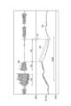
図4~図7は、心肺蘇生の際のTOIの時間的相対変化量を実際に測定した結果を示すグラフである。これらの図において、上段のグラフGaは、患者の頭部の酸素化ヘモグロビン濃度の時間的相対変化量を示し、グラフGaに含まれる振動部分は、胸骨圧迫を行っていること若しくは自発心拍があることを示す。下段のグラフGbは、患者の頭部のTOI(単位:%)の時間的相対変化量を示す。
FIGS. 4 to 7 are graphs showing the results of actually measuring the amount of change in TOI over time during cardiopulmonary resuscitation. In these figures, the upper graph Ga shows the amount of time-relative change in the oxygenated hemoglobin concentration of the patient's head, and the vibrating part included in the graph Ga shows chest compressions or spontaneous heartbeat. Show that. The lower graph Gb shows the amount of time-relative change in the TOI (unit:%) of the patient's head.
期間Paは、胸骨圧迫を行っている期間である。期間Pbは、心電図解析、及び電気ショックのための充電を行っている期間である。矢印A1は、電気ショックを行ったタイミングを示している。なお、これらのグラフにおいて、横軸は時間を表す。但し、図4~図7における時間軸のスケールは互いに異なる。
Period Pa is the period during which chest compressions are being performed. The period Pb is a period during which electrocardiogram analysis and charging for electric shock are performed. The arrow A1 indicates the timing of the electric shock. In these graphs, the horizontal axis represents time. However, the scales of the time axes in FIGS. 4 to 7 are different from each other.
図4を参照すると、胸骨圧迫を行っている期間PaではTOIは徐々に上昇するが、心電図解析を行う期間Pbに入った途端、TOIは下降を始める。そして、期間Pbの間、TOIは下降し続ける(図中の矢印A2)。このようなTOIの下降は、心電図解析を行っている間、胸骨圧迫を中断することに起因する。
Referring to FIG. 4, the TOI gradually increases in the period Pa during chest compressions, but the TOI begins to decrease as soon as the period Pb in which the electrocardiogram analysis is performed is entered. Then, during the period Pb, the TOI continues to decrease (arrow A2 in the figure). Such a decrease in TOI is due to interruption of chest compressions during ECG analysis.
また、図5を参照すると、胸骨圧迫(期間Pa)によってTOIを上昇させても、その途中に複数回の心電図解析(期間Pb)を行うと、そのたびにTOIが下降し、胸骨圧迫によるTOIの増加分の多くを打ち消してしまうことがわかる。その結果、TOIの上昇が緩慢となり、心肺蘇生に時間を要する原因となる。
Further, referring to FIG. 5, even if the TOI is increased by chest compressions (period Pa), the TOI decreases each time the electrocardiogram analysis (period Pb) is performed a plurality of times during the process, and the TOI due to chest compressions is performed. It can be seen that many of the increases in are canceled out. As a result, the increase in TOI slows down, causing time-consuming cardiopulmonary resuscitation.
このような課題に対し、本発明者らは、患者のTOIの大きさが、電気ショックによる除細動の成否に影響することを見出した。図6は、難治性VFに対して除細動が成功した例である。
In response to such problems, the present inventors have found that the size of the patient's TOI affects the success or failure of defibrillation due to electric shock. FIG. 6 is an example of successful defibrillation for a refractory VF.
図6に示す例では、除細動器1を搬入してTOIの測定を開始(矢印A3)した後、電気ショック(DC)を複数回行っている。なお、図中の枠内の数値は、各タイミングにおけるTOIの値である。このうち電気ショック(DC)時の枠内の数値は、心電図解析の直前におけるTOIの値である。1回目の心拍再開(Return of Spontaneous Circulation:ROSC)ののち再び心室細動(VF)が起こり(矢印A4)、その後、電気ショック(DC)による2回目の心拍再開(ROSC)により蘇生が成功している。
In the example shown in FIG. 6, after the defibrillator 1 is carried in and the TOI measurement is started (arrow A3), an electric shock (DC) is performed a plurality of times. The numerical values in the frame in the figure are TOI values at each timing. Of these, the numerical value in the frame at the time of electric shock (DC) is the value of TOI immediately before the electrocardiogram analysis. After the first resumption of heartbeat (Return of Spontaneous Circulation: ROSC), ventricular fibrillation (VF) occurred again (arrow A4), and then resuscitation was successful by the second resumption of heartbeat (ROSC) by electric shock (DC). ing.
図6に示す例を参照すると、除細動器1の搬入時にはTOIの時間的相対変化量が30%であり、その後の胸骨圧迫によってTOIの時間的相対変化量が徐々に上昇している。1回目から3回目の電気ショック(DC)における心電図解析前のTOIは41%~42%であり、これらの電気ショックでは心拍再開(ROSC)は不成功となっている。しかし、4回目の電気ショック(DC)における心電図解析前のTOIの時間的相対変化量は50%であり、1回目の心拍再開(ROSC)に成功している。また、心室細動(VF)に戻ったのちの5回目の電気ショック(DC)における心電図解析前のTOIの時間的相対変化量は62%であり、2回目の心拍再開(ROSC)に成功している。
Referring to the example shown in FIG. 6, the time-relative change amount of TOI is 30% at the time of carrying in the defibrillator 1, and the time-relative change amount of TOI gradually increases due to the subsequent chest compressions. The TOI before electrocardiographic analysis in the first to third electric shocks (DC) was 41% to 42%, and heart rate resumption (ROSC) was unsuccessful in these electric shocks. However, the amount of temporal relative change in TOI before the electrocardiogram analysis in the fourth electric shock (DC) was 50%, and the first heartbeat resumption (ROSC) was successful. In addition, the relative change in TOI before electrocardiographic analysis in the fifth electric shock (DC) after returning to ventricular fibrillation (VF) was 62%, and the second heartbeat resumption (ROSC) was successful. ing.
図7に示す例では、無脈性電気活動(Pulseless Electrical Activity:PEA)ののち、気道確保(Tracheal Intubation:TI)、エピネフリン投与(epi)を経て心室細動(VF)が出現し、1回目の電気ショック(DC)を行っている。その後、2回目の電気ショック(DC)を行っているが、1回目及び2回目とも心拍再開(ROSC)は不成功となっている。その後、3回目の電気ショック(DC)により心拍再開(ROSC)し、蘇生が成功している。1回目及び2回目の電気ショック(DC)における心電図解析前のTOIの時間的相対変化量はそれぞれ43%,45%であり、3回目の電気ショック(DC)における心電図解析前のTOIの時間的相対変化量は56%となっている。
In the example shown in FIG. 7, pulseless electrical activity (PEA) is followed by airway management (Tracheal Intubation: TI) and epinephrine administration (epi), followed by ventricular fibrillation (VF), which is the first time. I am doing an electric shock (DC). After that, a second electric shock (DC) was performed, but the resumption of heartbeat (ROSC) was unsuccessful in both the first and second times. After that, the heartbeat was resumed (ROSC) by the third electric shock (DC), and the resuscitation was successful. The temporal relative changes in the TOI before the electrocardiogram analysis in the first and second electric shocks (DC) were 43% and 45%, respectively, and the temporal changes in the TOI before the electrocardiogram analysis in the third electric shock (DC), respectively. The relative change amount is 56%.
図6及び図7に示された例によれば、患者のTOIが胸骨圧迫によって上昇した後に電気ショックを行うと、除細動の成功率が有意に向上することがわかる。これらの例では、TOIの時間的相対変化量が45%以下であるときに行った電気ショックは全て不成功となり、TOIの時間的相対変化量が50%以上であるときに行った電気ショックは全て成功している。
According to the examples shown in FIGS. 6 and 7, it can be seen that the success rate of defibrillation is significantly improved when the patient's TOI is increased by chest compressions and then an electric shock is applied. In these examples, all electric shocks performed when the relative temporal change in TOI is 45% or less are unsuccessful, and electric shocks performed when the relative temporal change in TOI is 50% or more are unsuccessful. Everything is successful.
したがって、例えば45%~50%の範囲内にしきい値を設定し、TOIの時間的相対変化量がこのしきい値を超えていることを条件に、心電図解析および電気ショックを行い、TOIの時間的相対変化量がこのしきい値を超えない場合には、心電図解析および電気ショックを行わずに胸骨圧迫を優先させる。これにより、除細動の成功率を高め、心電図解析及び電気ショックの回数を減らすことができる。
Therefore, for example, a threshold value is set in the range of 45% to 50%, and an electrocardiogram analysis and an electric shock are performed on the condition that the amount of temporal relative change of TOI exceeds this threshold value, and the time of TOI is performed. If the relative relative change does not exceed this threshold, priority is given to thoracic compression without ECG analysis and electrical shock. This can increase the success rate of defibrillation and reduce the number of electrocardiographic analyzes and electric shocks.
但し、図6及び図7のTOIは時間的相対値なので、周囲の環境、患者の年齢、患者の体型等に応じて変動すると考えられる。したがって、上述した45%~50%という数値範囲はあくまで一例であって、この範囲外の数値をしきい値として設定する方がよい場合もある。
However, since the TOI in FIGS. 6 and 7 is a relative value in time, it is considered that the TOI varies depending on the surrounding environment, the age of the patient, the body shape of the patient, and the like. Therefore, the above-mentioned numerical range of 45% to 50% is just an example, and it may be better to set a numerical value outside this range as a threshold value.
その場合であっても、本発明者らが有する多数のデータから考慮すると、しきい値が40%~60%の範囲内に含まれていれば、除細動の成功率を概ね高めることができる。また、取得するTOIが時間的相対値である場合であっても、TOIの時間的相対値と除細動の成否との関係についてのデータを多くの患者から取得すれば、概ね良好なしきい値を設定することは可能である。
Even in that case, considering the large number of data possessed by the present inventors, if the threshold value is within the range of 40% to 60%, the success rate of defibrillation can be generally increased. can. In addition, even if the acquired TOI is a temporal relative value, if data on the relationship between the temporal relative value of TOI and the success or failure of defibrillation is acquired from many patients, a generally good threshold value is obtained. It is possible to set.
本実施形態では、TOI測定部11(ステップST3)において取得したTOIがしきい値を超えていることを条件として、ECG測定部6(ステップST6)において患者の心電図を測定する。したがって、TOIがしきい値を超えている場合に心電図解析および電気ショックを行い、TOIがしきい値を超えない場合には胸骨圧迫を継続できるので、電気ショックによる除細動の成功率を高め、心電図解析及び電気ショックの回数を減らすことができる。
In the present embodiment, the ECG measuring unit 6 (step ST6) measures the patient's electrocardiogram on condition that the TOI acquired by the TOI measuring unit 11 (step ST3) exceeds the threshold value. Therefore, if the TOI exceeds the threshold, ECG analysis and electric shock can be performed, and if the TOI does not exceed the threshold, thoracic compression can be continued, increasing the success rate of defibrillation due to electric shock. , The number of electrocardiogram analysis and electric shock can be reduced.
本実施形態のように、TOI測定部11は、患者の体内へ測定光を入射する光入射部31と、患者の体内を伝搬した測定光を検出して測定光の強度に応じた検出信号を生成する光検出部32と、検出信号に基づいてTOIに関する数値を算出するTOI演算部5と、を有してもよい。また、TOIに関する数値の取得を開始するステップST3は、患者の体内への測定光の入射を開始する光入射ステップST31と、患者の体内を伝搬した測定光の検出を開始して測定光の強度に応じた検出信号を生成し始める光検出ステップST32と、検出信号に基づいてTOIに関する数値の算出を開始する演算ステップST33と、を含んでもよい。この場合、患者のTOIに関する数値を非侵襲的に且つ簡便に測定できるので、患者及び救助者の負担を軽減できる。
As in the present embodiment, the TOI measurement unit 11 detects the light incident unit 31 that injects the measurement light into the patient's body and the measurement light that has propagated inside the patient's body, and outputs a detection signal according to the intensity of the measurement light. It may have a light detection unit 32 to be generated, and a TOI calculation unit 5 to calculate a numerical value related to TOI based on the detection signal. Further, in step ST3 for starting the acquisition of the numerical value related to TOI, the light incident step ST31 for starting the incident of the measured light into the patient's body and the photoincident step ST31 for starting the detection of the measured light propagating in the patient's body are started and the intensity of the measured light is started. It may include a light detection step ST32 that starts to generate a detection signal according to the above, and a calculation step ST33 that starts calculation of a numerical value related to TOI based on the detection signal. In this case, since the numerical value related to the TOI of the patient can be measured non-invasively and easily, the burden on the patient and the rescuer can be reduced.
本実施形態のように、電気ショック部9は、ECG測定部6による心電図の測定結果に基づいて患者への電気ショックが必要と判断された場合に、電気ショックのための電気エネルギを電極パッド4から出力してもよい。また、ステップST8において患者への電気ショックが必要と判断された場合に、電気ショックステップST9において電気ショックのための電気エネルギを電極パッド4から出力してもよい。これにより、除細動のための電気ショックを好適に行うことができる。
As in the present embodiment, when the electric shock unit 9 determines that an electric shock to the patient is necessary based on the measurement result of the electrocardiogram by the ECG measuring unit 6, the electric shock unit 9 applies electric energy for the electric shock to the electrode pad 4. You may output from. Further, when it is determined in step ST8 that an electric shock to the patient is necessary, the electric energy for the electric shock may be output from the electrode pad 4 in the electric shock step ST9. This makes it possible to suitably perform an electric shock for defibrillation.
本実施形態のように、表示モニタ10は、TOIに関する数値がしきい値を超えない場合に、患者に対する胸骨圧迫を継続すべきことを救助者に知らせてもよい。また、TOIに関する数値がしきい値を超えない場合に、情報伝達ステップST7において患者に対する胸骨圧迫を継続すべきことを救助者に知らせてもよい。これにより、TOIがしきい値を超えない場合に救助者に胸骨圧迫の継続を促して、TOIの低下を抑制することができる。
As in the present embodiment, the display monitor 10 may inform the rescuer that chest compressions on the patient should be continued when the numerical value related to TOI does not exceed the threshold value. The rescuer may also be informed that chest compressions on the patient should be continued in signaling step ST7 if the value for TOI does not exceed the threshold. This can encourage the rescuer to continue chest compressions when the TOI does not exceed the threshold and suppress the decline in the TOI.
本実施形態のように、しきい値は、TOIの時間的相対変化量に換算して、40%~60%の範囲内に含まれるいずれかの値であってもよい。また、しきい値は、TOIの時間的相対変化量に換算して、45%~50%の範囲内に含まれるいずれかの値であってもよい。本発明者らの知見によれば、例えばこのような範囲内の或るしきい値を超えた場合に、電気ショックによる除細動の成功率が顕著に上昇する。
As in the present embodiment, the threshold value may be any value included in the range of 40% to 60% in terms of the amount of relative change in TOI over time. Further, the threshold value may be any value included in the range of 45% to 50% in terms of the amount of relative change over time of TOI. According to the findings of the present inventors, for example, when a certain threshold value within such a range is exceeded, the success rate of defibrillation due to electric shock is significantly increased.
除細動のための装置及び方法は、上述した実施形態及び構成例に限られるものではなく、他に様々な変形が可能である。例えば、上記実施形態では、TOIの測定方法として近赤外分光法を例示したが、TOIの測定方法はこれに限らず、他に様々な方法を用いることができる。
The device and method for defibrillation are not limited to the above-described embodiments and configurations, and various other modifications are possible. For example, in the above embodiment, near-infrared spectroscopy has been exemplified as a method for measuring TOI, but the method for measuring TOI is not limited to this, and various other methods can be used.
上記実施形態による除細動のための装置は、患者の酸素飽和度に関する数値を取得する酸素飽和度測定部と、患者への電気ショックの要否を判断するために患者の心電図を測定する心電図測定部と、酸素飽和度測定部において取得した数値がしきい値を超えていることを条件として、心電図測定部における患者の心電図の測定を開始させる制御部と、を備える。
The device for defibrillation according to the above embodiment has an oxygen saturation measuring unit that acquires a numerical value related to the oxygen saturation of the patient and an electrocardiogram that measures the electrocardiogram of the patient in order to determine the necessity of electric shock to the patient. It includes a measuring unit and a control unit for starting the measurement of the patient's electrocardiogram in the electrocardiogram measuring unit on condition that the numerical value acquired in the oxygen saturation measuring unit exceeds the threshold value.
上記実施形態による除細動のための方法は、患者の酸素飽和度に関する数値の取得を開始するステップと、酸素飽和度に関する数値がしきい値を超えていることを条件として患者の心電図を測定するステップと、心電図の測定結果に基づいて患者への電気ショックの要否を判断するステップと、を含む。
The method for defibrillation according to the above embodiment measures the patient's electrocardiogram on the condition that the acquisition of the oxygen saturation value of the patient is started and the value of the oxygen saturation exceeds the threshold value. And the step of determining the necessity of electric shock to the patient based on the measurement result of the electrocardiogram.
上記の装置において、酸素飽和度測定部は、患者の体内へ測定光を入射する光入射部と、患者の体内を伝搬した測定光を検出して測定光の強度に応じた検出信号を生成する光検出部と、検出信号に基づいて酸素飽和度に関する数値を算出する演算部と、を有する構成としてもよい。
In the above device, the oxygen saturation measuring unit detects the light incident portion that incidents the measurement light into the patient's body and the measurement light that has propagated inside the patient's body, and generates a detection signal according to the intensity of the measurement light. The configuration may include a light detection unit and a calculation unit that calculates a numerical value related to oxygen saturation based on the detection signal.
上記の方法において、酸素飽和度に関する数値の取得を開始するステップは、患者の体内への測定光の入射を開始する光入射ステップと、患者の体内を伝搬した測定光の検出を開始して測定光の強度に応じた検出信号を生成し始める光検出ステップと、検出信号に基づいて酸素飽和度に関する数値の算出を開始する演算ステップと、を含む構成としてもよい。
In the above method, the steps for starting the acquisition of the numerical value related to the oxygen saturation are the light incident step for starting the incident of the measured light into the patient's body and the detection of the measured light propagating in the patient's body for measurement. The configuration may include a light detection step that starts generating a detection signal according to the intensity of light, and a calculation step that starts calculation of a numerical value related to oxygen saturation based on the detection signal.
これらの装置及び方法によれば、患者の酸素飽和度に関する数値を非侵襲的に且つ簡便に測定できるので、患者及び救助者の負担を軽減できる。
According to these devices and methods, the numerical value related to the oxygen saturation of the patient can be measured non-invasively and easily, so that the burden on the patient and the rescuer can be reduced.
上記の装置は、電気ショック部を更に備え、電気ショック部は、心電図測定部による心電図の測定結果に基づいて患者への電気ショックが必要と判断された場合に、電気ショックのための電気エネルギを電極から出力する構成としてもよい。上記の方法は、電気ショックステップを更に含み、判断するステップにおいて患者への電気ショックが必要と判断された場合に、電気ショックステップにおいて電気ショックのための電気エネルギを電極から出力する構成としてもよい。これにより、除細動のための電気ショックを好適に行うことができる。
The above device further includes an electric shock unit, which provides electrical energy for an electric shock when it is determined that an electric shock to the patient is necessary based on the electrocardiogram measurement results of the electrocardiogram measuring unit. It may be configured to output from an electrode. The above method may further include an electric shock step, and when it is determined that an electric shock to the patient is necessary in the determination step, the electric energy for the electric shock may be output from the electrode in the electric shock step. .. This makes it possible to suitably perform an electric shock for defibrillation.
上記の装置は、情報伝達部を更に備え、情報伝達部は、酸素飽和度に関する数値がしきい値を超えない場合に、患者に対する胸骨圧迫を継続すべきことを救助者に知らせる構成としてもよい。上記の方法は、情報伝達ステップを更に含み、酸素飽和度に関する数値がしきい値を超えない場合に、情報伝達ステップにおいて患者に対する胸骨圧迫を継続すべきことを救助者に知らせる構成としてもよい。これにより、酸素飽和度がしきい値を超えない場合に救助者に胸骨圧迫の継続を促して、酸素飽和度の低下を抑制することができる。
The device may further include a transmission unit, which may be configured to inform the rescuer that chest compressions should be continued on the patient if the oxygen saturation value does not exceed the threshold. .. The above method may further include a signal transfer step and may be configured to inform the rescuer that chest compressions on the patient should be continued in the signal transfer step if the oxygen saturation value does not exceed the threshold. This can encourage the rescuer to continue chest compressions when the oxygen saturation does not exceed the threshold and suppress the decrease in oxygen saturation.
上記の装置及び方法において、しきい値は、酸素飽和度の時間的相対変化量に換算して、40%~60%の範囲内に含まれるいずれかの値であってもよい。また、しきい値は、酸素飽和度の時間的相対変化量に換算して、45%~50%の範囲内に含まれるいずれかの値であってもよい。本発明者らの知見によれば、例えばこのような範囲内のしきい値を超えた場合に、電気ショックによる除細動の成功率が顕著に上昇する。
In the above apparatus and method, the threshold value may be any value included in the range of 40% to 60% in terms of the amount of relative change in oxygen saturation over time. Further, the threshold value may be any value included in the range of 45% to 50% in terms of the amount of relative change in oxygen saturation over time. According to the findings of the present inventors, for example, when the threshold value within such a range is exceeded, the success rate of defibrillation due to electric shock is significantly increased.
実施形態は、電気ショックによる除細動の成功率を高め、心電図解析及び電気ショックの回数を減らすことができる除細動のための装置及び方法として利用可能である。
The embodiment can be used as a device and method for defibrillation that can increase the success rate of defibrillation by electric shock and reduce the number of electrocardiographic analysis and electric shock.
1…除細動器、2…本体部、3…NIRSセンサ、4…電極パッド、5…TOI演算部、6…ECG測定部、7…判定部、8…ECG解析部、9…電気ショック部、10…表示モニタ、11…TOI測定部、12…制御部、31…光入射部、32…光検出部、33…ホルダー、34…ケーブル、51…制御部、52…モニタ部、53…指示部、54…指示入力部、321,322…光検出器。
1 ... Defibrillator, 2 ... Main body, 3 ... NIRS sensor, 4 ... Electrode pad, 5 ... TOI calculation unit, 6 ... ECG measurement unit, 7 ... Judgment unit, 8 ... ECG analysis unit, 9 ... Electric shock unit 10, Display monitor, 11 ... TOI measurement unit, 12 ... Control unit, 31 ... Optical incident unit, 32 ... Optical detection unit, 33 ... Holder, 34 ... Cable, 51 ... Control unit, 52 ... Monitor unit, 53 ... Instruction Unit, 54 ... Instruction input unit, 321, 322 ... Photodetector.
Claims (12)
- 患者の酸素飽和度に関する数値を取得する酸素飽和度測定部と、
前記患者への電気ショックの要否を判断するために前記患者の心電図を測定する心電図測定部と、
前記酸素飽和度測定部において取得した数値がしきい値を超えていることを条件として、前記心電図測定部における前記患者の心電図の測定を開始させる制御部と、
を備える、除細動のための装置。 An oxygen saturation measuring unit that acquires numerical values related to the patient's oxygen saturation,
An electrocardiogram measuring unit that measures an electrocardiogram of the patient in order to determine the necessity of electric shock to the patient, and an electrocardiogram measuring unit.
A control unit for starting the measurement of the patient's electrocardiogram in the electrocardiogram measurement unit, provided that the numerical value acquired in the oxygen saturation measurement unit exceeds the threshold value.
A device for defibrillation. - 前記酸素飽和度測定部は、
前記患者の体内へ測定光を入射する光入射部と、
前記患者の体内を伝搬した前記測定光を検出して前記測定光の強度に応じた検出信号を生成する光検出部と、
前記検出信号に基づいて酸素飽和度に関する数値を算出する演算部と、
を有する、請求項1に記載の装置。 The oxygen saturation measuring unit is
The light incident part that injects the measured light into the patient's body,
A photodetector that detects the measurement light propagating in the patient's body and generates a detection signal according to the intensity of the measurement light.
An arithmetic unit that calculates a numerical value related to oxygen saturation based on the detection signal,
The device according to claim 1. - 電気ショック部を更に備え、
前記電気ショック部は、前記心電図測定部による前記心電図の測定結果に基づいて前記患者への電気ショックが必要と判断された場合に、電気ショックのための電気エネルギを電極から出力する、請求項1または2に記載の装置。 Further equipped with an electric shock part,
The electric shock unit outputs electric energy for an electric shock from an electrode when it is determined that an electric shock to the patient is necessary based on the measurement result of the electrocardiogram by the electrocardiogram measuring unit. Or the device according to 2. - 情報伝達部を更に備え、
前記情報伝達部は、前記酸素飽和度測定部により取得された数値が前記しきい値を超えない場合に、前記患者に対する胸骨圧迫を継続すべきことを救助者に知らせる、請求項1~3のいずれか1項に記載の装置。 Further equipped with an information transmission unit,
The information transmission unit informs the rescuer that chest compressions for the patient should be continued when the numerical value acquired by the oxygen saturation measurement unit does not exceed the threshold value, according to claims 1 to 3. The device according to any one item. - 前記しきい値は、酸素飽和度の時間的相対変化量に換算して、40%~60%の範囲内に含まれるいずれかの値である、請求項1~4のいずれか1項に記載の装置。 The threshold value is any one of the values included in the range of 40% to 60% in terms of the amount of relative change in oxygen saturation over time, according to any one of claims 1 to 4. Equipment.
- 前記しきい値は、酸素飽和度の時間的相対変化量に換算して、45%~50%の範囲内に含まれるいずれかの値である、請求項5に記載の装置。 The apparatus according to claim 5, wherein the threshold value is any value included in the range of 45% to 50% in terms of the amount of relative change in oxygen saturation over time.
- 患者の酸素飽和度に関する数値の取得を開始するステップと、
前記酸素飽和度に関する数値がしきい値を超えていることを条件として前記患者の心電図を測定するステップと、
前記心電図の測定結果に基づいて前記患者への電気ショックの要否を判断するステップと、
を含む、除細動のための方法。 Steps to start getting numbers for a patient's oxygen saturation,
The step of measuring the electrocardiogram of the patient on condition that the numerical value related to the oxygen saturation exceeds the threshold value, and
The step of determining the necessity of electric shock to the patient based on the measurement result of the electrocardiogram, and
Methods for defibrillation, including. - 前記酸素飽和度に関する数値の取得を開始するステップは、
前記患者の体内への測定光の入射を開始する光入射ステップと、
前記患者の体内を伝搬した前記測定光の検出を開始して前記測定光の強度に応じた検出信号を生成し始める光検出ステップと、
前記検出信号に基づいて酸素飽和度に関する数値の算出を開始する演算ステップと、
を含む、請求項7に記載の方法。 The step of starting the acquisition of the numerical value regarding the oxygen saturation is
A light incident step that initiates the incident of the measured light into the patient's body,
A photodetection step that starts detecting the measurement light propagating in the patient's body and starts generating a detection signal according to the intensity of the measurement light.
A calculation step for starting calculation of a numerical value related to oxygen saturation based on the detection signal, and
7. The method of claim 7. - 電気ショックステップを更に含み、
前記判断するステップにおいて前記患者への電気ショックが必要と判断された場合に、前記電気ショックステップにおいて電気ショックのための電気エネルギを電極から出力する、請求項7または8に記載の方法。 Including additional electric shock steps,
The method according to claim 7 or 8, wherein when it is determined in the determination step that an electric shock to the patient is necessary, the electric energy for the electric shock is output from the electrode in the electric shock step. - 情報伝達ステップを更に含み、
前記酸素飽和度に関する数値が前記しきい値を超えない場合に、前記情報伝達ステップにおいて前記患者に対する胸骨圧迫を継続すべきことを救助者に知らせる、請求項7~9のいずれか1項に記載の方法。 Including further communication steps,
13. the method of. - 前記しきい値は、酸素飽和度の時間的相対変化量に換算して、40%~60%の範囲内に含まれるいずれかの値である、請求項7~10のいずれか1項に記載の方法。 The threshold value is any one of the values included in the range of 40% to 60% in terms of the amount of relative change in oxygen saturation over time, according to any one of claims 7 to 10. the method of.
- 前記しきい値は、酸素飽和度の時間的相対変化量に換算して、45%~50%の範囲内に含まれるいずれかの値である、請求項11に記載の方法。 The method according to claim 11, wherein the threshold value is any value included in the range of 45% to 50% in terms of the amount of relative change in oxygen saturation over time.
Priority Applications (3)
| Application Number | Priority Date | Filing Date | Title |
|---|---|---|---|
| US18/008,498 US20230210434A1 (en) | 2020-06-19 | 2021-04-19 | Defibrillation device and method |
| EP21826635.1A EP4137200A1 (en) | 2020-06-19 | 2021-04-19 | Defibrillation device and method |
| JP2022532338A JPWO2021256074A1 (en) | 2020-06-19 | 2021-04-19 |
Applications Claiming Priority (2)
| Application Number | Priority Date | Filing Date | Title |
|---|---|---|---|
| JP2020106189 | 2020-06-19 | ||
| JP2020-106189 | 2020-06-19 |
Publications (1)
| Publication Number | Publication Date |
|---|---|
| WO2021256074A1 true WO2021256074A1 (en) | 2021-12-23 |
Family
ID=79267754
Family Applications (1)
| Application Number | Title | Priority Date | Filing Date |
|---|---|---|---|
| PCT/JP2021/015880 WO2021256074A1 (en) | 2020-06-19 | 2021-04-19 | Defibrillation device and method |
Country Status (4)
| Country | Link |
|---|---|
| US (1) | US20230210434A1 (en) |
| EP (1) | EP4137200A1 (en) |
| JP (1) | JPWO2021256074A1 (en) |
| WO (1) | WO2021256074A1 (en) |
Citations (4)
| Publication number | Priority date | Publication date | Assignee | Title |
|---|---|---|---|---|
| JP2005046606A (en) | 2003-06-27 | 2005-02-24 | Zoll Medical Corp | Cardiopulmonary resuscitator equipped with feedback from measurement of pulse and/or oxygen in blood |
| US20150148856A1 (en) * | 2013-11-27 | 2015-05-28 | Zoll Medical Corporation | Rescuer protection from electrical shock during defibrillation |
| JP2016513546A (en) * | 2013-03-14 | 2016-05-16 | ゾール メディカル コーポレイションZOLL Medical Corporation | Identification of shocks based on previous shocks |
| JP2017164033A (en) * | 2016-03-14 | 2017-09-21 | 株式会社フジタ医科器械 | Automated external defibrillator |
-
2021
- 2021-04-19 JP JP2022532338A patent/JPWO2021256074A1/ja active Pending
- 2021-04-19 EP EP21826635.1A patent/EP4137200A1/en active Pending
- 2021-04-19 WO PCT/JP2021/015880 patent/WO2021256074A1/en unknown
- 2021-04-19 US US18/008,498 patent/US20230210434A1/en active Pending
Patent Citations (4)
| Publication number | Priority date | Publication date | Assignee | Title |
|---|---|---|---|---|
| JP2005046606A (en) | 2003-06-27 | 2005-02-24 | Zoll Medical Corp | Cardiopulmonary resuscitator equipped with feedback from measurement of pulse and/or oxygen in blood |
| JP2016513546A (en) * | 2013-03-14 | 2016-05-16 | ゾール メディカル コーポレイションZOLL Medical Corporation | Identification of shocks based on previous shocks |
| US20150148856A1 (en) * | 2013-11-27 | 2015-05-28 | Zoll Medical Corporation | Rescuer protection from electrical shock during defibrillation |
| JP2017164033A (en) * | 2016-03-14 | 2017-09-21 | 株式会社フジタ医科器械 | Automated external defibrillator |
Also Published As
| Publication number | Publication date |
|---|---|
| EP4137200A1 (en) | 2023-02-22 |
| JPWO2021256074A1 (en) | 2021-12-23 |
| US20230210434A1 (en) | 2023-07-06 |
Similar Documents
| Publication | Publication Date | Title |
|---|---|---|
| US20220249026A1 (en) | System and Method for Characterizing Cardiac Arrhythmia | |
| US11350884B2 (en) | Physiological metric estimation rise and fall limiting | |
| US6241684B1 (en) | Exercise workout support device | |
| JP2017512581A (en) | System and method for detecting fluctuations in a user's heart rate | |
| EP3781029B1 (en) | Device, system and method for supporting detection of return of spontaneous circulation during cardiopulmonary resuscitation | |
| US8974396B1 (en) | Mobile plethysmographic device | |
| US20140376788A1 (en) | Compensating for motion induced artifacts in a physiological signal extracted from a single video | |
| JP2018518303A (en) | Determining the return of spontaneous circulatory flow during cardiopulmonary resuscitation | |
| EP2229880A1 (en) | Headband integrated monitoring unit using an accelerometer | |
| US9629562B1 (en) | Mobile plethysmographic device | |
| US11229405B2 (en) | Neck-worn physiological monitor | |
| WO2019138327A1 (en) | Wearable ecg and auscultation monitoring system with sos and remote monitoring | |
| US20170172515A1 (en) | Neck-worn physiological monitor | |
| JP4407135B2 (en) | Exercise load intensity evaluation apparatus and exercise equipment | |
| WO2021256074A1 (en) | Defibrillation device and method | |
| KR102186260B1 (en) | Pad type cardiopulmonaryresuscitation aid device | |
| CN112469333A (en) | Device, system and method for detecting a pulse of a subject | |
| US20210161401A1 (en) | Electrocardiograph | |
| JP4093085B2 (en) | Exercise load intensity evaluation apparatus and exercise equipment | |
| WO2018231193A1 (en) | Apparatus and method for calculating a pulse deficit value | |
| Shimazaki et al. | Design of PPG-based heart rate sensor enabling motion artefact cancellation | |
| US20190246926A1 (en) | Device for detecting atrial fibrillation of a subject | |
| JP6817755B2 (en) | How to operate the concentration measuring device and the concentration measuring device | |
| US11938332B2 (en) | Method to provide computational analysis and feedback during a cardiac rescue | |
| US20230048327A1 (en) | Systems and methods of use for a wearable ultrasound blood flow sensor |
Legal Events
| Date | Code | Title | Description |
|---|---|---|---|
| 121 | Ep: the epo has been informed by wipo that ep was designated in this application |
Ref document number: 21826635 Country of ref document: EP Kind code of ref document: A1 |
|
| ENP | Entry into the national phase |
Ref document number: 2022532338 Country of ref document: JP Kind code of ref document: A |
|
| ENP | Entry into the national phase |
Ref document number: 2021826635 Country of ref document: EP Effective date: 20221115 |
|
| NENP | Non-entry into the national phase |
Ref country code: DE |