WO2021255992A1 - 電解質測定装置 - Google Patents
電解質測定装置 Download PDFInfo
- Publication number
- WO2021255992A1 WO2021255992A1 PCT/JP2021/004486 JP2021004486W WO2021255992A1 WO 2021255992 A1 WO2021255992 A1 WO 2021255992A1 JP 2021004486 W JP2021004486 W JP 2021004486W WO 2021255992 A1 WO2021255992 A1 WO 2021255992A1
- Authority
- WO
- WIPO (PCT)
- Prior art keywords
- noise
- electrode
- potential
- unit
- flow path
- Prior art date
- Legal status (The legal status is an assumption and is not a legal conclusion. Google has not performed a legal analysis and makes no representation as to the accuracy of the status listed.)
- Ceased
Links
Images


Classifications
-
- G—PHYSICS
- G01—MEASURING; TESTING
- G01N—INVESTIGATING OR ANALYSING MATERIALS BY DETERMINING THEIR CHEMICAL OR PHYSICAL PROPERTIES
- G01N27/00—Investigating or analysing materials by the use of electric, electrochemical, or magnetic means
- G01N27/26—Investigating or analysing materials by the use of electric, electrochemical, or magnetic means by investigating electrochemical variables; by using electrolysis or electrophoresis
- G01N27/28—Electrolytic cell components
- G01N27/30—Electrodes, e.g. test electrodes; Half-cells
- G01N27/333—Ion-selective electrodes or membranes
-
- G—PHYSICS
- G01—MEASURING; TESTING
- G01N—INVESTIGATING OR ANALYSING MATERIALS BY DETERMINING THEIR CHEMICAL OR PHYSICAL PROPERTIES
- G01N27/00—Investigating or analysing materials by the use of electric, electrochemical, or magnetic means
- G01N27/26—Investigating or analysing materials by the use of electric, electrochemical, or magnetic means by investigating electrochemical variables; by using electrolysis or electrophoresis
- G01N27/416—Systems
Definitions
- the present invention relates to an electrolyte measuring device.
- An electrolyte analysis unit having multiple ion-selective electrodes (ISE) corresponding to the ions to be detected in order to measure the ion concentration of potassium, sodium, chloride, etc. in biological samples such as blood. , Installed in devices such as automatic analyzers. Since the electrolyte analysis unit can perform clinical tests automatically, quickly, and continuously, it is used by the electrolyte analysis unit alone or as an element of an apparatus such as an automatic biochemical analyzer.
- ISE ion-selective electrodes
- the ion-selective electrode When measuring the ion concentration, the ion-selective electrode is used in combination with the reference electrode, and the target ion concentration can be obtained by measuring the potential difference generated between the ion-selective electrode and the reference electrode.
- samples such as blood (particularly serum and plasma) and urine, which are biological samples.
- these samples are measured as they are using an ion-selective electrode, that is, by a so-called non-dilution method.
- a so-called dilution method in which a predetermined amount of a diluted solution is added to a predetermined amount of a sample to dilute it, and then the measurement is performed using an ion-selective electrode.
- the dilution method has the features that the required amount of sample is small, the concentration of coexisting substances such as proteins and lipids in the measuring solution is low, the influence of contamination by coexisting substances is small, and the stability of the ion-selective electrode is high.
- a flow cell type ion-selective electrode is used in which a sample (measurement liquid) flows inside the ion-selective electrode and a reference liquid flows inside the reference electrode in order to carry out clinical tests quickly and continuously.
- the combination of the dilution method and the flow cell type ion-selective electrode is currently the mainstream.
- a container called a dilution tank is used for diluting the sample, and the diluted sample prepared in the dilution tank is sent to a flow cell type ion-selective electrode through a pipe for measurement. Dispense the internal standard solution into the dilution tank alternately with the sample, and measure alternately with the sample.
- the concentration of electrolytes in the living body is usually maintained in a narrow concentration range, and even a slight change in concentration is significant clinically or therapeutically. Therefore, extremely high measurement accuracy is required for ion-selective electrodes, and various techniques have been developed to reduce measurement errors as much as possible.
- the electrical conduction can be cut off by interrupting the flow of the solution in the measurement flow path and the waste liquid pipe so as to be discontinuous, and the noise induced in the drainage pipe and the drainage tank.
- An electrolyte measuring device has been proposed, which is configured so as not to be mixed with the electrodes of the measuring flow path.
- the electrolyte analysis unit that measures the potential difference between the ion-selective electrode and the reference electrode does not output the normal potential due to the electrical noise mixed in the measurement system. These electrical noises are derived from subtle changes in the state of the components electrically connected to the measurement system and the installation environment of the analyzer.
- Patent Document 1 a method for improving the quantification accuracy such as electrical shielding of the measurement system and measurement at the timing when the mechanical component does not operate is common. There was a problem that the degree of freedom in design was limited.
- the present invention has been made in view of the above problems, and when an electrolyte is detected using an ion-selective electrode, the degree of freedom in design is limited by correcting electrical noise. It is an object of the present invention to provide an electrolyte measuring device that realizes measurement with high quantitative accuracy.
- the electrolyte measuring device includes a noise detection electrode connected to a flow path, and uses the potential of the noise detection electrode to reduce the noise contained in the potential of the ion-selective electrode.
- the degree of freedom in design is not limited by correcting the electrical noise, and the quantification accuracy is high.
- the measurement can be realized.
- FIG. It is a schematic diagram which shows the structure of the electrolyte measuring apparatus 100 which concerns on Embodiment 1.
- FIG. It is a figure which shows the electric resistance which each part of an electrolyte measurement unit 1 has. A modification of the electrolyte measurement unit 1 is shown.
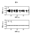
- electrolyte measuring apparatus 100 shows the result of measuring the V and V-V S in the conditions I S and I R is detected.
- FIG. It is a block diagram of the electrolyte measurement unit 1 which concerns on Embodiment 3.
- FIG. It is a block diagram of the electrolyte measuring apparatus 100 which concerns on Embodiment 4.
- FIG. It is a block diagram of the electrolyte measurement unit 1 in Embodiment 5.
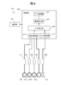
- FIG. 1 is a schematic view showing the configuration of the electrolyte measuring device 100 according to the first embodiment of the present invention.
- the electrolyte measuring device 100 includes an electrolyte measuring unit 1, a display unit 2, an input unit 3, a control unit 4, a concentration calculation unit 5, a noise removing unit 6, a noise detecting unit 7, and a potential measuring unit 8. To prepare for.
- the electrolyte measurement unit 1 includes three types of ion-selective electrodes 101 (chlorine ion electrode 101a, potassium ion electrode 101b, sodium ion electrode 101c), noise detection electrode 102, reference electrode 104, pinch valve 105, vacuum suction nozzle 106, and shipper.
- the ion-selective electrode 101 for example, a flow cell type ion-selective electrode can be used.
- the number of ion electrodes in the ion-selective electrode 101 can be changed according to the number of ion species to be measured.
- the ion-selective electrode 101 generates a potential according to the ion concentration in the sample (sample).
- the noise detection electrode 102 comes into contact with the sample liquid drawn from the shipper nozzle 107, and the noise detection unit 7 and the potential measurement unit 9 measure the potential difference between the common grounds. It is desirable that the noise detection electrode 102 is made of a material having as little electromotive force as possible due to contact with the sample liquid and having low ion selectivity. For example, precious metals such as gold and platinum, alloys and the like can be mentioned. Alternatively, a coating agent satisfying the above conditions may be used to cover the surface in contact with the sample solution.
- the reference liquid is contained in the reference liquid bottle 161, and the reference liquid is introduced into the flow path in the reference electrode 104 by the sipper syringe pump 133.
- the reference liquid for example, an aqueous potassium chloride solution can be used.
- the reference electrode 104 generates an electric potential according to the ion concentration in the reference liquid.
- the internal standard liquid (IS) is contained in the internal standard liquid bottle 141, and the internal standard liquid is dispensed into the diluting tank 110 by the internal standard liquid syringe pump 131 and the internal standard liquid supply nozzle 109.
- the sample is dispensed into the dilution tank 110 by a sampling mechanism (not shown).
- the diluted solution bottle 151 contains the diluted solution, and the diluted solution is dispensed into the diluted solution tank 110 by the syringe pump 132 for the diluted solution and the diluted solution supply nozzle 108 and mixed with the sample.
- the internal standard solution or the measuring solution in which the sample and the diluted solution are mixed (hereinafter referred to as "sample") is introduced into the dilution tank 110.
- the solenoid valve 121 is opened, the pinch valve 105 is closed, and the sipper syringe pump 133 is pulled so that the reference liquid is transferred from the reference liquid bottle 161 to the reference electrode. Introduced into the stream within 104. Further, in order to discharge the liquid accumulated in the shipper syringe pump 133, the solenoid valve 122 is closed, the solenoid valve 125 is opened, and the shipper syringe pump 133 is pushed.
- the reference liquid introduced into the flow path in the reference electrode 104 and the sample introduced into the ion-selective electrode 101 come into contact with each other at the liquid junction 120, and the ion-selective electrode 101 and the reference electrode 104 electrically pass through the liquid. It will be connected to.
- the vacuum suction nozzle 106 is lowered and the vacuum pump 112 is driven to drive the diluting tank.
- the liquid (sample or internal standard liquid) remaining in the 110 is sucked and discarded in the waste liquid tank 111.
- the reference liquid introduced into the reference electrode 104 is discarded in the waste liquid tank 111 by operating the solenoid valve 121, the vacuum pump 112, and the shipper syringe pump 133.
- the potential difference (electromotive force) between the reference electrode 104 and each ion-selective electrode 101 changes depending on the ion concentration of the analysis target in the sample introduced into the flow path in the ion-selective electrode 101.
- the potential measuring unit 9 measures the electromotive force and outputs the measurement result (time transition of the electromotive force, etc.) to the concentration calculation unit 5.
- electromotive force may be simply referred to as "potential”.
- a predetermined time width including a time for calculating the ion concentration may be referred to as a “predetermined time domain”.
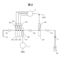
- FIG. 2 is a diagram showing the electrical resistance of each part of the electrolyte measuring unit 1.
- the resistance values of 204, 205, 206, 207, and 208 are R1, R2, R3, R4, R5, R6, and R7, respectively.
- the electric resistance 207 shall be sufficiently smaller than the other electric resistances.
- V E ISE -E REF + I S ⁇ R 2 + (I S + I R) ⁇ R 3 (1)
- V S E x -E REF + I S ⁇ R 2 + (I S + I R) ⁇ R 3 (2)
- the noise removing unit 6 corrects the noise contained in the potential measured by the potential measuring unit 8 (reduces the noise component) by using the equation 3.
- V-V S E ISE -E x (3)
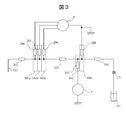
- FIG. 3 shows a modified example of the electrolyte measuring unit 1.
- the noise detection electrode 102 is provided at a position that is in contact with the reference liquid and has the same potential as the potential of the flow path position where the reference electrode 104 is arranged.
- E x can be considered to be the same every measurement. Therefore E ISE of formula 3 can be obtained from the measurement results of V and V S.
- the noise removing unit 6 can perform a correction operation according to this principle.
- the waste liquid containing the sample liquid, the internal standard liquid, and the reference liquid is drawn into the flow path connected from the liquid connection portion 120 to the waste liquid tank 111 by the syringe pump 133, and is discharged to the waste liquid tank 111.
- the mixing ratio of the liquid flowing into the waste liquid flow path is not constant over time, so the ion concentration and temperature of the liquid in the waste liquid flow path fluctuate with each measurement. do. Therefore, when a noise detection electrode is provided in the flow path, it is highly possible that the measured potential includes the potential change due to changes in the ion concentration and temperature of the liquid in addition to the potential change derived from the noise to be detected. , Not suitable for installing noise detection electrodes.
- a method of correcting fluctuations in electrical noise mixed in the flow path from the values of a plurality of ion-selective electrodes without using a noise detection electrode can be considered.
- the effect of electrical noise on the potential is affected by each electrode. different. Therefore, the correction by the equation (3) cannot be performed.
- additional operations such as performing potential calibration for each measurement are required, which may reduce the degree of freedom of the measurement sequence intended by the present invention. be. Therefore, it is desirable to use a noise detection electrode made of a material having low ion selectivity.
- FIG 4 shows the results of using the electrolyte measuring apparatus 100 was measured V and V-V S in the conditions I S and I R is detected. From this result, it can be confirmed that the fluctuation range of the measurement result is reduced by 10 times or more after the noise correction.
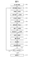
- FIG. 5 is a flowchart illustrating an analysis procedure using the electrolyte measuring device 100. Each step of FIG. 5 will be described below.
- step S501 when the user inputs an operation start instruction from the input unit 3, the control unit 4 drives the electrolyte measurement unit 1 and starts the measurement operation.
- step S502 the electrolyte measuring unit 1 drives the internal standard liquid syringe pump 131, the electromagnetic valves 123 and 126, introduces the internal standard liquid from the internal standard liquid supply nozzle 109 into the diluting tank 110, and introduces the internal standard liquid into the measuring flow path. Introduce the internal standard solution to.
- step S503 the potential measuring unit 9 measures the potential difference (electromotive force) between the reference electrode 104 and each ion-selective electrode 101, and outputs the potential difference (electromotive force) to the noise removing unit 6 as an internal standard liquid potential VIS.
- step S504 the noise potential VS_IS of the internal standard solution measured by the noise detection unit 7 is measured and output to the noise removal unit 6.
- the noise removing unit 6 performs a noise correction operation to correct the internal standard liquid potential VIS .
- the noise removing unit 6 outputs the average value of the corrected internal standard liquid potential VIS at an arbitrary time to the concentration calculation unit 5.
- the electrolyte measuring unit 1 discharges the remaining internal standard solution from the dilution tank 110 before carrying out the next step S507.
- step S507 the electrolyte measurement unit 1 introduces the sample into the dilution tank 110 by a sampling mechanism (not shown in FIG. 1), drives the syringe pump 132 for the diluent, and introduces the diluent from the diluent supply nozzle 108. , Obtain a sample that is a mixture.
- the solenoid valve 121 and the solenoid valve 125 are closed, the pinch valve 105 and the solenoid valve 122 are opened, the shipper nozzle 107 is lowered into the dilution tank 110, and the shipper syringe pump 133 is driven to drive the measurement liquid into the measurement flow path.
- step S508 the potential measuring unit 9 measures the potential difference (electromotive force) between the reference electrode 104 and each ion-selective electrode 101, and outputs the sample potential V samp to the noise removing unit 6.
- step S509 the noise detection unit 7 acquires the noise potential V samp of the sample.
- the noise removing unit 6 performs a noise correction operation to correct the sample potential V samp .
- the noise removing unit 6 outputs the average value of the corrected sample potential V samp potentials at an arbitrary time to the concentration calculation unit 5.
- the electrolyte measurement unit 1 discharges the remaining sample in the dilution tank 110.
- the concentration calculation unit 5 calculates the ion concentration in the sample based on the average value of the corrected internal standard liquid potential VIS and the average value of the corrected sample potential V samp. For example, the difference between the potentials is calculated.
- E X noise detector 7 and the solution is produced by contacting assuming hardly depends on the electrolyte concentration in the sample liquid, the average value of the internal standard solution potential V IS and the sample potential V samp by obtaining the difference between the average value, it is possible to ignore the influence of the electromotive force E X generated by the contact of the noise detection electrode 102 and the sample liquid.
- step S513 the display unit 2 displays the calculated ion concentration (measurement result).
- step S514 the control unit 4 determines whether or not there is the next sample. For example, prior to step S501, the number of samples to be measured is input to the electrolyte measuring device 100 in advance, and the control unit 4 compares the number of samples to be measured with the number of measured samples to prepare the next sample. It is possible to determine the presence or absence of. If there is a next sample (YES), the process returns to step S502 and the ion concentration is measured in the same manner. If there is no next sample (NO), the process proceeds to step S515 to end the measurement.
- the number of samples to be measured is input to the electrolyte measuring device 100 in advance, and the control unit 4 compares the number of samples to be measured with the number of measured samples to prepare the next sample. It is possible to determine the presence or absence of. If there is a next sample (YES), the process returns to step S502 and the ion concentration is measured in the same manner. If there is no next sample (NO), the process proceeds to step S515 to end the measurement.
- Electrolyte measuring apparatus 100 though the potential V detected by the noise detecting electrode 102, it is possible to correct the potential V S potential measuring section 9 was measured. This makes it possible to realize measurement with high quantitative accuracy. Furthermore, by cutting off the flow of solution between the measurement flow path and the waste liquid pipe, electrical conduction is cut off, and it is not necessary to perform measurement at the timing when the mechanical parts do not operate, so measurement accuracy can be improved without reducing the degree of freedom in design. Can be enhanced.
- FIG. 6 is a block diagram of the electrolyte measurement unit 1 in the second embodiment.
- the same reference numbers are given to the same components as those shown in FIG.
- the differences from the apparatus configuration of FIG. 2 will be described in detail.
- Other configurations are the same as those in the first embodiment.
- the noise detection electrodes 601, 602, and 603 are arranged at positions having the same potentials as the potentials generated in each of the shipper nozzle 107, the reference electrode 104, and the reference liquid bottle 161. Each electrode is connected to the noise detection unit 7 and measures the respective potential.
- the electrical resistances 610, 620, and 630 between each noise detection electrode 601 to 603 and the sample liquid or the reference liquid are shown for convenience of explanation.
- the current that becomes noise of the measured potential V acquired by the potential measuring unit 9 may be mixed into the measuring system due to an abnormality of a component or the like.
- a component or the like For example, there are abnormalities such as (a) a shipper nozzle 107, (b) a reference liquid bottle 161 and (c) a flow path between the ion-selective electrode 101 and the reference electrode 104.
- the noise mixing path can be estimated by referring to the potentials of the noise detection electrodes 102, 601, 602, and 603 acquired by the noise detection unit 7.
- the possibility of noise mixing from the shipper nozzle 107 is excluded, and the reference liquid bottle 161 is abnormal or the ion-selective electrode 101 is referred to. It can be narrowed down only to abnormalities in the flow path between the electrode 104 and the flow path. This makes it possible to specify the variable value mixing path by noise correction. Therefore, it is possible to reduce the burden on the operator in the recovery work from the abnormal state of the electrolyte measuring device 100.
- noise detection electrodes 601 to 603 are arranged at positions having the same potentials as the potentials generated in each of the shipper nozzle 107, the reference electrode 104, and the reference liquid bottle 161. Based on the fluctuation of the potential detected by 601 to 603, the mixing path of the current-derived noise is estimated. As a result, the work load of maintenance management can be reduced.
- Embodiment 3 In the second embodiment, a method of reducing the work load of maintenance management by specifying the mixing path of electrical noise has been described. On the other hand, when the order of the values of the electric resistances 201, 202, and 203 for each measurement fluctuates greatly due to the mixing of air bubbles or the like in the flow path through which the sample liquid and the reference liquid pass, the mixing path of electrical noise is used. It will be difficult to identify. In Embodiment 3 of the present invention, a method capable of specifying a noise mixing path even in such a case will be described.
- FIG. 7 is a block diagram of the electrolyte measurement unit 1 according to the third embodiment.
- the same reference numbers are given to the same components as those shown in FIG. 2 or 6.
- the differences from the apparatus configuration of FIG. 2 or FIG. 6 will be described in detail.
- Other configurations are the same as those of the first and second embodiments.
- the ammeter 710 is arranged between the reference electrode 104 and the analog ground. Further, the switches 731, 732, 733, and 734 connected to the noise detection electrodes 102, 601, 602, and 603 are arranged, and the voltage source 720 connected to each switch is arranged. Although not shown here, each switch is connected to the control unit 4 and can be switched individually.
- each switch is set to be connected to the noise detection unit 7.
- the value of the voltage source 720 is known, and a predetermined voltage can be applied to the noise detection electrodes 102, 601, 602, and 603, respectively, by switching the switch.
- the voltage value of the voltage source 720 and the current value acquired by the current meter 710 for each switching operation are obtained. It can be used to determine the values of electrical resistance 201, 202, 203. In particular, since this operation is performed after the measured voltage is measured, this operation does not affect the measured voltage. Further, the ammeter 710 can acquire the current value even when the measured voltage is acquired.
- the measured voltage and the current value show the same fluctuation pattern, it is assumed that it is the influence of the current flowing in the flow path. If the same fluctuation pattern is not shown, it is assumed that it is affected by other noise, and it can also be used to determine the noise type.
- the noise mixing path can be accurately specified even in the case where bubbles are mixed in each flow path and the values of the respective electric resistances 201 to 203 change for each measurement. It is possible to do.
- the electrolyte measuring device 100 switches the switches 731 to 734 so as to apply a voltage to any of the noise detection electrodes 601 to 603, and measures the electric resistances 201 to 203. Thereby, for example, even in the case where the electric resistance of the flow path fluctuates due to the mixing of air bubbles or the like into the flow path, it is possible to specify the mixing path of electrical noise.
- FIG. 8 is a block diagram of the electrolyte measuring device 100 according to the fourth embodiment.
- the electrolyte measuring device 100 in the fourth embodiment includes an ion-selective electrode 101, a noise detection electrode 102, a reference electrode 104, and electrical resistance values of various electrodes 801, 802, 803, 804, 812, a control unit 805, and a power supply unit 806. It includes a data transmission unit 807, a concentration calculation unit 808, a noise removal unit 809, a potential measurement unit 910, and a noise detection unit 711.
- the electrolyte measuring device 100 shown in FIG. 8 can be attached to a living body and fixed, and can measure the electrolyte concentration contained in a sample solution such as sweat or blood that comes into contact with the ion-selective electrode 101 and the noise detection electrode 102 exposed on the outside of the device. .. As a fixing method, it can be attached to the skin using an adhesive or invasively embedded in a living body. As a result, the electrolyte measuring device 100 of FIG. 8 is configured as a wearable device.
- the ion-selective electrode 101 outputs a potential by the ions contained in the sample, as in the first to third embodiments.
- the biological component is measured as a sample.
- the electrolyte measuring device 100 is attached to the skin surface, ions contained in sweat and the like can be measured.
- ions contained in blood and the like can be measured.
- the potential of the reference electrode 104 needs to be kept constant. In the first to third embodiments, this is realized by supplying the reference liquid. In the fourth embodiment, since there is no mechanism for supplying the reference liquid, it is necessary to use an alternative means. For example, by constantly immersing the reference electrode 104 in the reference liquid using an encapsulation tube having a liquid connection portion or by connecting a constant voltage circuit or the like to the reference electrode 104, the reference liquid can be supplied without being supplied. It is possible to realize the same role as the reference electrode 104 in the first to third embodiments.
- the noise removing unit 809 corrects the measurement potential by using the signal of the noise detection electrode 102 installed in the vicinity of the ion-selective electrode 101, so that it is wearable without a special shield structure. Even with an electrolyte measuring device, the measurement accuracy can be improved.
- the noise correction method using the noise detection electrode 102 connected to the measurement flow path realizes measurement with high quantification accuracy without reducing the degree of freedom in design in order to suppress noise mixing. I explained how to do it.
- these methods target the electrical noise flowing in the sample liquid, etc., and cannot correct the electrical noise directly mixed in the ion-selective electrode due to the influence of the electric field caused by the generation of static electricity, etc. ..
- a configuration example for realizing a method for solving these problems will be described.
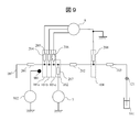
- FIG. 9 is a block diagram of the electrolyte measurement unit 1 in the fifth embodiment.
- the same reference numbers are assigned to the same components as those shown in FIGS. 2 to 8.
- the differences from the apparatus configurations of FIGS. 2 to 8 will be described in detail.
- an electric field noise detection electrode 901 that is not directly connected to the measurement flow path is provided.
- the electric field noise detection electrode 901 is connected to the ammeter 902.
- the amount of the current can be detected by the electric field noise detection electrode 901.
- a shape of the electric field noise detection electrode 901 a sphere, a cylinder / cone, a quadrangular prism / quadrangular prism, a polyhedron, or the like is used.
- the correction when the current I noise mixed in the chlorine ion electrode 101a and flowing through the ground connected to the reference electrode affects the measurement system will be described.
- the potential V noise measured at this time is shown as follows using the electric resistances R 202 , R 204 , R 208 , and the electromotive force V of the chlorine ion electrode 101a.
- V noise V + (R 202 + R 204 + R 208 ) ⁇ I noise (4)
- the I corr measured by the ammeter 902 is not the same value as the Noise , but it is considered that there is some correlation with the Noise.
- This correlation in advance from, for example, an actually measured value and correcting V noise using I corr , it is possible to remove the noise component related to I noise from the potential V.
- V noise ⁇ A ⁇ I corr represents the true value of the potential V according to the equation 4, and remove the noise component by using the coefficient A. Be done.
- Other appropriate calculation formulas may be used.
- a plurality of electric field noise detection electrodes 901 and ammeters 902 can be installed, and each can be measured at the same time.
- the direction of electric field noise generation and the mixing path can be estimated by detecting the state of spatial electric field noise using each position and current amount, so more accurate correction can be made. Will be possible. Further, since it is possible to estimate whether or not the electric field noise is caused by the defect of the component from the state of the spatial electric field noise, it is possible to reduce the burden on the recovery worker when the defect occurs.
- the electrolyte measuring device 100 can correct the electric noise directly mixed in the ion-selective electrode 101 due to the influence of the electric field due to the generation of static electricity and the like, and further improve the quantification accuracy. Can be done.
- the present invention is not limited to the above-described embodiment, and includes various modifications.
- the above-described embodiment has been described in detail in order to explain the present invention in an easy-to-understand manner, and is not necessarily limited to the one including all the described configurations.
- it is possible to replace a part of the configuration of one embodiment with the configuration of another embodiment and it is also possible to add the configuration of another embodiment to the configuration of one embodiment.
- the chlorine ion electrode 101a, the potassium ion electrode 101b, and the sodium ion electrode 101c are exemplified as examples of the ion-selective electrode 101, but the present invention can also be applied to other ion species.
- the functional unit that performs arithmetic processing such as the control unit 4, the concentration calculation unit 5, and the noise removal unit 6 can be configured by using hardware such as a circuit device that implements the functions.
- Software that implements the function can also be configured by executing an arithmetic unit such as a CPU (Central Processing Unit).
- Electrolyte measuring device 1 ... Electrolyte measuring unit 2 ; Display unit 3 ; Input unit 4 ; Control unit 5 ; Concentration calculation unit 6 ; Noise removal unit 7 ... Noise detection unit 8 ... Potential measurement unit 101 ... Ion-selective electrode 102 ... Noise detection electrode 104 ... Reference electrode 105 ... Pinch valve 106 ... Vacuum suction nozzle 107 ... Shipper nozzle 108 ... Diluting liquid supply nozzle 109 ... Internal standard liquid supply nozzle 110 ... Diluting tank 111 ... Waste liquid tank 112 ... Vacuum pump 121-127 ... Electromagnetic valve 131 ... Internal standard liquid Syringe pump 132 ... Diluting liquid syringe pump 133 ... Shipper Syringe pump 141 ... Internal standard liquid bottle 151 ... Diluting liquid bottle 161 ... Reference liquid bottle
Landscapes
- Chemical & Material Sciences (AREA)
- Life Sciences & Earth Sciences (AREA)
- Health & Medical Sciences (AREA)
- Physics & Mathematics (AREA)
- Chemical Kinetics & Catalysis (AREA)
- Electrochemistry (AREA)
- Molecular Biology (AREA)
- Analytical Chemistry (AREA)
- Biochemistry (AREA)
- General Health & Medical Sciences (AREA)
- General Physics & Mathematics (AREA)
- Immunology (AREA)
- Pathology (AREA)
- Automatic Analysis And Handling Materials Therefor (AREA)
- Investigating Or Analyzing Materials By The Use Of Electric Means (AREA)
Applications Claiming Priority (2)
| Application Number | Priority Date | Filing Date | Title |
|---|---|---|---|
| JP2020102837A JP7448422B2 (ja) | 2020-06-15 | 2020-06-15 | 電解質測定装置 |
| JP2020-102837 | 2020-06-15 |
Publications (1)
| Publication Number | Publication Date |
|---|---|
| WO2021255992A1 true WO2021255992A1 (ja) | 2021-12-23 |
Family
ID=79197644
Family Applications (1)
| Application Number | Title | Priority Date | Filing Date |
|---|---|---|---|
| PCT/JP2021/004486 Ceased WO2021255992A1 (ja) | 2020-06-15 | 2021-02-08 | 電解質測定装置 |
Country Status (2)
| Country | Link |
|---|---|
| JP (1) | JP7448422B2 (enExample) |
| WO (1) | WO2021255992A1 (enExample) |
Cited By (1)
| Publication number | Priority date | Publication date | Assignee | Title |
|---|---|---|---|---|
| WO2025207965A1 (en) * | 2024-03-29 | 2025-10-02 | Beckman Coulter, Inc. | Optimization of ion-selective electrode measurement |
Citations (10)
| Publication number | Priority date | Publication date | Assignee | Title |
|---|---|---|---|---|
| JPS63216533A (ja) * | 1987-03-05 | 1988-09-08 | テルモ株式会社 | 生体情報測定装置 |
| JPH01209348A (ja) * | 1988-02-17 | 1989-08-23 | Kuraray Co Ltd | イオン濃度などの測定装置 |
| JPH02236168A (ja) * | 1989-03-09 | 1990-09-19 | New Japan Radio Co Ltd | 接触型試料採取装置と接触型分析装置 |
| JPH06510463A (ja) * | 1991-11-08 | 1994-11-24 | ビア メディカル コーポレイション | 干渉低減回路を有する電気化学式測定装置 |
| JP2006170973A (ja) * | 2004-11-18 | 2006-06-29 | Shotaro Oka | 測定器 |
| JP2011102729A (ja) * | 2009-11-10 | 2011-05-26 | Sharp Corp | 分析チップ装置、分析チップ装置に用いる化学センサチップ収納アダプター及び分析装置ならびに分析チップ装置を用いた分析方法 |
| JP2012528329A (ja) * | 2009-05-29 | 2012-11-12 | ライフ テクノロジーズ コーポレーション | 電気化学的反応を行うための装置および方法 |
| JP3212682U (ja) * | 2017-06-22 | 2017-09-28 | 味の素株式会社 | 体液受入れ構造体およびそれを有する体液分析装置 |
| JP2019219407A (ja) * | 2014-12-19 | 2019-12-26 | スティヒティング・イメック・ネーデルラントStichting IMEC Nederland | ドリフト補償されたイオンセンサ |
| JP2020052005A (ja) * | 2018-09-28 | 2020-04-02 | 株式会社日立ハイテク | 電解質測定装置 |
-
2020
- 2020-06-15 JP JP2020102837A patent/JP7448422B2/ja active Active
-
2021
- 2021-02-08 WO PCT/JP2021/004486 patent/WO2021255992A1/ja not_active Ceased
Patent Citations (10)
| Publication number | Priority date | Publication date | Assignee | Title |
|---|---|---|---|---|
| JPS63216533A (ja) * | 1987-03-05 | 1988-09-08 | テルモ株式会社 | 生体情報測定装置 |
| JPH01209348A (ja) * | 1988-02-17 | 1989-08-23 | Kuraray Co Ltd | イオン濃度などの測定装置 |
| JPH02236168A (ja) * | 1989-03-09 | 1990-09-19 | New Japan Radio Co Ltd | 接触型試料採取装置と接触型分析装置 |
| JPH06510463A (ja) * | 1991-11-08 | 1994-11-24 | ビア メディカル コーポレイション | 干渉低減回路を有する電気化学式測定装置 |
| JP2006170973A (ja) * | 2004-11-18 | 2006-06-29 | Shotaro Oka | 測定器 |
| JP2012528329A (ja) * | 2009-05-29 | 2012-11-12 | ライフ テクノロジーズ コーポレーション | 電気化学的反応を行うための装置および方法 |
| JP2011102729A (ja) * | 2009-11-10 | 2011-05-26 | Sharp Corp | 分析チップ装置、分析チップ装置に用いる化学センサチップ収納アダプター及び分析装置ならびに分析チップ装置を用いた分析方法 |
| JP2019219407A (ja) * | 2014-12-19 | 2019-12-26 | スティヒティング・イメック・ネーデルラントStichting IMEC Nederland | ドリフト補償されたイオンセンサ |
| JP3212682U (ja) * | 2017-06-22 | 2017-09-28 | 味の素株式会社 | 体液受入れ構造体およびそれを有する体液分析装置 |
| JP2020052005A (ja) * | 2018-09-28 | 2020-04-02 | 株式会社日立ハイテク | 電解質測定装置 |
Cited By (1)
| Publication number | Priority date | Publication date | Assignee | Title |
|---|---|---|---|---|
| WO2025207965A1 (en) * | 2024-03-29 | 2025-10-02 | Beckman Coulter, Inc. | Optimization of ion-selective electrode measurement |
Also Published As
| Publication number | Publication date |
|---|---|
| JP7448422B2 (ja) | 2024-03-12 |
| JP2021196261A (ja) | 2021-12-27 |
Similar Documents
| Publication | Publication Date | Title |
|---|---|---|
| US11709147B2 (en) | Electrolyte measuring device | |
| EP4001910A1 (en) | Analysis device and analysis method | |
| US20240345018A1 (en) | Electrolyte analyzer and analysis method | |
| EP4105651B1 (en) | Electrolyte analysis apparatus | |
| WO2021255992A1 (ja) | 電解質測定装置 | |
| JP2022103367A (ja) | 自動分析装置 | |
| CN111788479B (zh) | 自动分析装置、自动分析方法 | |
| JP7789787B2 (ja) | イオン選択性電極分析器における同時かつ選択的な洗浄および検出 | |
| US8888989B2 (en) | Method and apparatus for electrolyte measurements | |
| EP4524559A1 (en) | Analyzing device, and state detecting method | |
| EP4653876A1 (en) | Analysis device and rinsing method for flow path of analysis device | |
| JPH05322843A (ja) | イオン電極を用いた電解質分析装置 | |
| WO2025220386A1 (ja) | 電解質分析装置、制御方法 | |
| JP2003207481A (ja) | 電解質測定装置 | |
| WO2025154515A1 (ja) | 電解質濃度分析装置、電解質濃度分析方法 | |
| JPH04221753A (ja) | イオン濃度分析装置用シリンジ |
Legal Events
| Date | Code | Title | Description |
|---|---|---|---|
| 121 | Ep: the epo has been informed by wipo that ep was designated in this application |
Ref document number: 21824904 Country of ref document: EP Kind code of ref document: A1 |
|
| NENP | Non-entry into the national phase |
Ref country code: DE |
|
| 122 | Ep: pct application non-entry in european phase |
Ref document number: 21824904 Country of ref document: EP Kind code of ref document: A1 |