WO2021255912A1 - Crimp securing structure of bolt, crimp securing method for crimp bolt, and crimping die - Google Patents
Crimp securing structure of bolt, crimp securing method for crimp bolt, and crimping die Download PDFInfo
- Publication number
- WO2021255912A1 WO2021255912A1 PCT/JP2020/024098 JP2020024098W WO2021255912A1 WO 2021255912 A1 WO2021255912 A1 WO 2021255912A1 JP 2020024098 W JP2020024098 W JP 2020024098W WO 2021255912 A1 WO2021255912 A1 WO 2021255912A1
- Authority
- WO
- WIPO (PCT)
- Prior art keywords
- caulking
- bolt
- recess
- die
- crimp
- Prior art date
Links
- 238000002788 crimping Methods 0.000 title claims abstract description 10
- 238000000034 method Methods 0.000 title claims description 9
- 239000002184 metal Substances 0.000 claims abstract description 33
- 239000007769 metal material Substances 0.000 claims abstract description 25
- 230000002093 peripheral effect Effects 0.000 claims abstract description 12
- 239000000463 material Substances 0.000 description 4
- 230000013011 mating Effects 0.000 description 1
Images


Classifications
-
- F—MECHANICAL ENGINEERING; LIGHTING; HEATING; WEAPONS; BLASTING
- F16—ENGINEERING ELEMENTS AND UNITS; GENERAL MEASURES FOR PRODUCING AND MAINTAINING EFFECTIVE FUNCTIONING OF MACHINES OR INSTALLATIONS; THERMAL INSULATION IN GENERAL
- F16B—DEVICES FOR FASTENING OR SECURING CONSTRUCTIONAL ELEMENTS OR MACHINE PARTS TOGETHER, e.g. NAILS, BOLTS, CIRCLIPS, CLAMPS, CLIPS OR WEDGES; JOINTS OR JOINTING
- F16B35/00—Screw-bolts; Stay-bolts; Screw-threaded studs; Screws; Set screws
- F16B35/04—Screw-bolts; Stay-bolts; Screw-threaded studs; Screws; Set screws with specially-shaped head or shaft in order to fix the bolt on or in an object
- F16B35/06—Specially-shaped heads
-
- B—PERFORMING OPERATIONS; TRANSPORTING
- B21—MECHANICAL METAL-WORKING WITHOUT ESSENTIALLY REMOVING MATERIAL; PUNCHING METAL
- B21D—WORKING OR PROCESSING OF SHEET METAL OR METAL TUBES, RODS OR PROFILES WITHOUT ESSENTIALLY REMOVING MATERIAL; PUNCHING METAL
- B21D39/00—Application of procedures in order to connect objects or parts, e.g. coating with sheet metal otherwise than by plating; Tube expanders
-
- F—MECHANICAL ENGINEERING; LIGHTING; HEATING; WEAPONS; BLASTING
- F16—ENGINEERING ELEMENTS AND UNITS; GENERAL MEASURES FOR PRODUCING AND MAINTAINING EFFECTIVE FUNCTIONING OF MACHINES OR INSTALLATIONS; THERMAL INSULATION IN GENERAL
- F16B—DEVICES FOR FASTENING OR SECURING CONSTRUCTIONAL ELEMENTS OR MACHINE PARTS TOGETHER, e.g. NAILS, BOLTS, CIRCLIPS, CLAMPS, CLIPS OR WEDGES; JOINTS OR JOINTING
- F16B37/00—Nuts or like thread-engaging members
- F16B37/04—Devices for fastening nuts to surfaces, e.g. sheets, plates
- F16B37/06—Devices for fastening nuts to surfaces, e.g. sheets, plates by means of welding or riveting
- F16B37/062—Devices for fastening nuts to surfaces, e.g. sheets, plates by means of welding or riveting by means of riveting
- F16B37/068—Devices for fastening nuts to surfaces, e.g. sheets, plates by means of welding or riveting by means of riveting by deforming the material of the support, e.g. the sheet or plate
Definitions
- the present invention relates to a crimping fixing structure for bolts, a caulking fixing method for caulking bolts, and a caulking die.
- the caulking bolt is a bolt that crimps and fixes the head of the bolt to a metal plate. Unlike a weld bolt, the caulking bolt does not need to be heated, so that the metal plate does not deform or discolor, and is widely used in the industrial field. ..
- the caulking bolt is generally a type in which a caulking recess is formed in the head seat surface and a type in which a caulking recess is formed in the upper end portion of the shaft portion immediately below the seat surface.
- a caulking bolt having a caulking recess on the upper surface of the head is also known.
- Japanese Unexamined Patent Publication No. 2017-155860 Japanese Unexamined Patent Publication No. 2019-138368 Japanese Unexamined Patent Publication No. 2004-324913
- an object of the present invention is to solve the above-mentioned conventional problems, and to provide a caulking fixing structure for a caulking bolt capable of firmly caulking and fixing a caulking bolt provided with a caulking recess on the upper surface of the head to a metal plate. It is to provide a caulking fixing method and a caulking die.
- the crimping fixing structure of the bolt of the present invention made to solve the above-mentioned problems is a caulking fixing structure of a bolt in which a caulking bolt is caulked and fixed to a metal plate, and the caulking bolt is provided with a caulking recess on the upper surface of the head.
- the thickness of the metal material press-fitted into the caulking recess is characterized by being thin at the peripheral portion of the caulking recess and thick at the central portion.
- a caulking bolt provided with a caulking recess on the upper surface of the head is placed on the surface of the metal plate with the head facing down, and the die is used.
- a caulking die having a convex portion formed on the surface and a recess for stress relief formed in the center of the convex portion is placed on the back surface of the metal plate, and a caulking bolt is driven into the metal plate with a punch to form a surface of the die. It is characterized in that a metal material is press-fitted into the caulking recess by the convex portion.
- the shape of the stress relaxation recess is not limited to the shape having a flat bottom surface, and various deformations are possible.
- the caulking die of the present invention made to solve the above-mentioned problems is a caulking die used for caulking and fixing a caulking bolt provided with a caulking recess on the upper surface of the head to a metal plate. It is characterized in that a convex portion is formed on the surface and a stress relaxation recess is formed in the central portion of the convex portion.
- the thickness of the metal material pressed into the caulking recess formed on the upper surface of the head of the caulking bolt is increased at the central portion of the caulking recess, and the thickness of the metal material at the central portion is increased.
- the press-fitting distance is smaller than that of the peripheral edge. Therefore, the metal material can flow deep into the caulking recess, the press-fitting distance of the metal material in the central portion is reduced, and the generation of excessive local stress in the caulking recess is suppressed. Therefore, the bolt head is not deformed or destroyed, and firm caulking and fixing are possible.
- caulking is performed using a caulking die having a stress relaxation recess formed in the center of the convex portion and a punch.
- the material can be press-fitted, and by letting a part of the metal material press-fitted into the caulking recess into the stress relaxation recess, it is possible to suppress the generation of excessive local stress. Therefore, the bolt head is not deformed or broken, and strong caulking and fixing are possible.
- caulking bolt It is a perspective view of a caulking bolt. It is a top view of the caulking bolt. It is sectional drawing which shows the caulking structure of the bolt of an embodiment. It is a perspective view of a caulking die. It is sectional drawing which shows the state before the start of caulking. It is sectional drawing which shows the state just before lowering a punch. It is sectional drawing which shows the state which lowered the punch. It is sectional drawing which shows the prior art.
- FIG. 1 is a perspective view of the caulking bolt 10 used in this embodiment
- FIG. 2 is a top view thereof.
- the caulking bolt 10 has a head portion 11 and a shaft portion 12, and a caulking recess 13 is formed on the upper surface of the head portion 11.
- the bottom surface of the caulking recess 13 is a flat surface
- the peripheral inner surface 14 of the caulking recess 13 has a tapered shape extending toward the bottom surface.
- an uneven portion 15 for preventing rotation is formed on the peripheral inner surface 14 of the caulking recess 13.
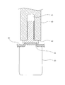
- FIG. 3 shows a caulking structure in which the caulking bolt 10 is caulked and fixed to a metal plate 30.
- the metal material of the metal plate 30 is plastically press-fitted into the caulking recess 13 of the caulking bolt 10, but the thickness of the metal material is thin at the peripheral edge of the caulking recess 13. , It is thicker in the center. That is, the metal material is deeply press-fitted at the peripheral edge of the caulking recess 13, thereby obtaining sufficient caulking strength. Further, the metal material also bites into the anti-rotation uneven portion 15 formed on the peripheral inner surface 14 of the caulking recess 13, and obtains sufficient anti-rotation strength.
- the press-fitting distance of the metal material is smaller than that in the peripheral portion.
- the thickness of the metal material press-fitted into the caulking recess 13 is constant, and this point is characteristic of the caulking structure of the present invention.
- the caulking die 20 is made of a hard metal, the upper surface 21 of the columnar main body is a flat surface, and a circular convex portion 22 is formed in the central portion thereof.
- the convex portion 22 has a role of press-fitting a metal plate into the inside of the caulking recess 13 of the caulking bolt 10 to plastically flow the metal material. Therefore, the outer diameter of the convex portion 22 is formed to be smaller than the inner diameter of the caulking recess 13.
- a stress relaxation recess 23 is formed in the center of the convex portion 22. As shown in FIG. 5, in this embodiment, the bottom surface of the stress relaxation recess 23 is flat. The height of the bottom surface of the stress relaxation recess 23 is an intermediate height between the surface 21 of the die and the convex portion 22. The specific dimensions are determined according to the material and thickness of the metal plate 30 as the mating material.
- the stress relaxation recess 23 is not limited to a shape having a flat bottom surface as in this embodiment, and for example, a conical convex shape, a ring-shaped groove or protrusion, a trapezoidal convex shape, etc. on the bottom surface, etc. Can also be formed into a shape.
- the caulking die 20 is arranged on the back surface of the metal plate 30, and the caulking bolt 10 is used. Is placed on the surface of the metal plate 30 with the head facing down. As in the conventional case, the caulking die 20 and the caulking bolt 10 are positioned so as to be on the same axis. In this state, the metal plate 30 is on the convex portion 22 of the caulking die 20.
- the punch 40 is arranged above the caulking bolt 10. The punch 40 is formed with a recess 41 into which the shaft portion 12 of the caulking bolt 10 is inserted, and the flat lower surface 42 has a larger diameter than the head portion 11 of the caulking bolt 10.
- the metal material of the metal plate is plastically flowed into the caulking recess 13 of the caulking bolt 10 by the convex portion 22 on the surface of the die 20 and press-fitted, and the caulking bolt 10 is caulked and fixed to the metal plate 30.
- the metal material is press-fitted deep into the caulking recess 13 by the circular convex portion 22 of the die 20 and adheres to the peripheral inner surface 14 of the tapered caulking recess 13 extending toward the bottom surface. At the same time, it bites into the uneven portion 15 for preventing rotation. As a result, excellent pull-out strength and anti-rotation strength can be obtained.
- the caulking fixing method of the present invention it is possible to suppress the generation of excessive local stress as compared with the case of using a conventional die having no stress relaxation recess 23. Therefore, the bolt head is not deformed or broken, and as shown in FIG. 3, strong caulking and fixing are possible.
- the area and depth of the stress relaxation recess 23 are determined according to the material and thickness of the metal plate 30, but the height of the bottom surface of the stress relaxation recess 23 is set between the surface 21 of the die and the convex portion 22. If the height is set to the middle, the metal plate 20 is surely pressurized even in the central portion of the stress relaxation recess 23, so that there is no possibility that the caulking strength is lowered.
- the shaft portion 12 of the caulking bolt 10 is used for attaching another member.
Abstract
The present invention is a crimp securing structure of a bolt, the structure being such that a crimp bolt 10 in which a crimping recess 13 is provided in the upper surface of a top part is secured by crimping to a metal sheet 30. The present invention is characterized in that the thickness of a metal material press-fitted into the crimping recess 13 of the crimp bolt is reduced at a central section so as to be less than that at a peripheral edge section of the crimping recess 13. In order to obtain this crimp securing structure, a crimping die 20 in which a stress-relief recess 23 is formed at a protruding central section is used to prevent the occurrence of excessive localized stress in the crimping recess 13.
Description
本発明は、ボルトのかしめ固定構造、かしめボルトのかしめ固定方法及びかしめダイスに関するものである。
The present invention relates to a crimping fixing structure for bolts, a caulking fixing method for caulking bolts, and a caulking die.
かしめボルトは、ボルトの頭部を金属板にかしめ固定するボルトであり、ウエルドボルトのように加熱する必要がないため金属板が変形したり変色することがなく、工業分野において広く用いられている。
The caulking bolt is a bolt that crimps and fixes the head of the bolt to a metal plate. Unlike a weld bolt, the caulking bolt does not need to be heated, so that the metal plate does not deform or discolor, and is widely used in the industrial field. ..
かしめボルトは特許文献1に示されるように、頭部座面にかしめ用凹部を形成したタイプと、座面直下の軸部の上端部にかしめ用凹部を形成したタイプが一般的であるが、特許文献3に示されるように、頭部上面にかしめ用凹部を備えたかしめボルトも知られている。
As shown in Patent Document 1, the caulking bolt is generally a type in which a caulking recess is formed in the head seat surface and a type in which a caulking recess is formed in the upper end portion of the shaft portion immediately below the seat surface. As shown in Patent Document 3, a caulking bolt having a caulking recess on the upper surface of the head is also known.
頭部上面にかしめ用凹部を備えたかしめボルトを金属板にかしめ固定する際には、凸形状のかしめダイスを金属板の裏面に配置し、かしめボルトを頭部を下向きとして金属板の表面に載せ、パンチによりボルト頭部を加圧する。このとき、金属板はかしめダイスの凸状部により加圧されて金属材料がボルトのかしめ用凹部内に圧入され、図8に示すようにかしめ固定が行われる。かしめ固定されたボルトの軸部は金属板から突出しているため、他の部材を取付けるために使用される。
When caulking a caulking bolt with a caulking recess on the upper surface of the head, place a convex caulking die on the back surface of the metal plate and place the caulking bolt on the surface of the metal plate with the head facing down. Place and pressurize the bolt head with a punch. At this time, the metal plate is pressed by the convex portion of the caulking die, the metal material is press-fitted into the caulking recess of the bolt, and the caulking is fixed as shown in FIG. Since the shaft portion of the crimped bolt protrudes from the metal plate, it is used for attaching other members.
強固なかしめ固定を行うためには、かしめ用凹部内に金属材料を塑性的に流動させ充満させる必要がある。しかしそのために加圧力を大きくすると、ダイスの凸状部によってかしめ用凹部内に圧入された金属材料の行き場がなくなり、かしめ用凹部内において過大な局所応力が発生してボルト頭部を変形又は破壊してしまう可能性がある。この場合にはかしめ強度が低下することとなる。またこの現象を避けるために加圧力を落とすと、かしめ用凹部の奥深くまで金属材料を圧入することができず、かしめ強度が低下することとなる。このように、頭部上面にかしめ用凹部を備えたかしめボルトを強固にかしめ固定することは、容易ではなかった。
In order to perform strong caulking fixing, it is necessary to plastically flow and fill the caulking recess with a metal material. However, when the pressing force is increased for that purpose, there is no place for the metal material press-fitted into the caulking recess due to the convex portion of the die, and excessive local stress is generated in the caulking recess to deform or break the bolt head. There is a possibility that it will be done. In this case, the caulking strength will decrease. Further, if the pressing force is reduced to avoid this phenomenon, the metal material cannot be press-fitted deep into the caulking recess, and the caulking strength is lowered. As described above, it has not been easy to firmly caulk and fix the caulking bolt provided with the caulking recess on the upper surface of the head.
従って本発明の目的は上記した従来の問題点を解決し、頭部上面にかしめ用凹部を備えたかしめボルトを、金属板に強固にかしめ固定することができるボルトのかしめ固定構造、かしめボルトのかしめ固定方法及びかしめダイスを提供することである。
Therefore, an object of the present invention is to solve the above-mentioned conventional problems, and to provide a caulking fixing structure for a caulking bolt capable of firmly caulking and fixing a caulking bolt provided with a caulking recess on the upper surface of the head to a metal plate. It is to provide a caulking fixing method and a caulking die.
上記の課題を解決するためになされた本発明のボルトのかしめ固定構造は、かしめボルトを金属板にかしめ固定したボルトのかしめ固定構造であって、かしめボルトは頭部上面にかしめ用凹部を備え、このかしめ用凹部内に圧入された金属材料の厚さを、かしめ用凹部の周縁部では薄く、中央部では厚くしたことを特徴とするものである。
The crimping fixing structure of the bolt of the present invention made to solve the above-mentioned problems is a caulking fixing structure of a bolt in which a caulking bolt is caulked and fixed to a metal plate, and the caulking bolt is provided with a caulking recess on the upper surface of the head. The thickness of the metal material press-fitted into the caulking recess is characterized by being thin at the peripheral portion of the caulking recess and thick at the central portion.
また上記の課題を解決するためになされた本発明のかしめボルトのかしめ固定方法は、頭部上面にかしめ用凹部を備えたかしめボルトを頭部を下向きとして金属板の表面に配置し、ダイスの表面に凸状部を形成するとともに、この凸状部の中央部に応力緩和用凹部を形成したかしめダイスを金属板の裏面に配置し、パンチでかしめボルトを金属板に打ち込み、ダイスの表面の凸状部により金属材料を前記かしめ用凹部内に圧入することを特徴とするものである。後述するように、この応力緩和用凹部の形状は平坦な底面を有する形状に限定されず、様々な変形が可能である。
Further, in the caulking fixing method of the caulking bolt of the present invention, which has been made to solve the above problems, a caulking bolt provided with a caulking recess on the upper surface of the head is placed on the surface of the metal plate with the head facing down, and the die is used. A caulking die having a convex portion formed on the surface and a recess for stress relief formed in the center of the convex portion is placed on the back surface of the metal plate, and a caulking bolt is driven into the metal plate with a punch to form a surface of the die. It is characterized in that a metal material is press-fitted into the caulking recess by the convex portion. As will be described later, the shape of the stress relaxation recess is not limited to the shape having a flat bottom surface, and various deformations are possible.
また、上記の課題を解決するためになされた本発明のかしめダイスは、頭部上面にかしめ用凹部を備えたかしめボルトを金属板にかしめ固定するために用いられるかしめダイスであって、ダイスの表面に凸状部を形成するとともに、この凸状部の中央部に応力緩和用凹部を形成したことを特徴とするものである。
Further, the caulking die of the present invention made to solve the above-mentioned problems is a caulking die used for caulking and fixing a caulking bolt provided with a caulking recess on the upper surface of the head to a metal plate. It is characterized in that a convex portion is formed on the surface and a stress relaxation recess is formed in the central portion of the convex portion.
本発明のボルトのかしめ固定構造は、かしめボルトの頭部上面に形成されたかしめ用凹部内に圧入された金属材料の厚さをかしめ用凹部の中央部では厚くし、中央部における金属材料の圧入距離を周縁部よりも小さくしている。このため、かしめ用凹部の奥深くまで金属材料を流動させることができ、しかも中央部における金属材料の圧入距離を小さくし、かしめ用凹部内における過大な局所応力の発生を抑制する。このため、ボルト頭部を変形させたり破壊してしまうことがなくなり、強固なかしめ固定が可能となる。
In the caulking fixing structure of the bolt of the present invention, the thickness of the metal material pressed into the caulking recess formed on the upper surface of the head of the caulking bolt is increased at the central portion of the caulking recess, and the thickness of the metal material at the central portion is increased. The press-fitting distance is smaller than that of the peripheral edge. Therefore, the metal material can flow deep into the caulking recess, the press-fitting distance of the metal material in the central portion is reduced, and the generation of excessive local stress in the caulking recess is suppressed. Therefore, the bolt head is not deformed or destroyed, and firm caulking and fixing are possible.
また、本発明のかしめボルトのかしめ固定方法は、凸状部の中央部に応力緩和用凹部を形成したかしめダイスとパンチを用いてかしめを行うので、凸状部によってかしめ用凹部の奥深くまで金属材料を圧入することができ、しかもかしめ用凹部内に圧入された金属材料の一部を応力緩和用凹部に逃がすことにより、過大な局所応力の発生を抑制することができる。このためボルト頭部を変形させたり破壊してしまうことがなくなり、強固なかしめ固定が可能となる。
Further, in the caulking fixing method of the caulking bolt of the present invention, caulking is performed using a caulking die having a stress relaxation recess formed in the center of the convex portion and a punch. The material can be press-fitted, and by letting a part of the metal material press-fitted into the caulking recess into the stress relaxation recess, it is possible to suppress the generation of excessive local stress. Therefore, the bolt head is not deformed or broken, and strong caulking and fixing are possible.
以下に本発明の実施形態を説明する。
図1はこの実施形態で用いられるかしめボルト10の斜視図、図2はその上面図である。これらの図に示されるように、このかしめボルト10は頭部11と軸部12を有し、頭部11の上面にかしめ用凹部13が形成されている。かしめ用凹部13の底面は平面であり、かしめ用凹部13の周囲内面14は底面に向かって拡がったテーパ状となっている。またこのかしめ用凹部13の周囲内面14には、回り止め用の凹凸部15が形成されている。 An embodiment of the present invention will be described below.
FIG. 1 is a perspective view of thecaulking bolt 10 used in this embodiment, and FIG. 2 is a top view thereof. As shown in these figures, the caulking bolt 10 has a head portion 11 and a shaft portion 12, and a caulking recess 13 is formed on the upper surface of the head portion 11. The bottom surface of the caulking recess 13 is a flat surface, and the peripheral inner surface 14 of the caulking recess 13 has a tapered shape extending toward the bottom surface. Further, an uneven portion 15 for preventing rotation is formed on the peripheral inner surface 14 of the caulking recess 13.
図1はこの実施形態で用いられるかしめボルト10の斜視図、図2はその上面図である。これらの図に示されるように、このかしめボルト10は頭部11と軸部12を有し、頭部11の上面にかしめ用凹部13が形成されている。かしめ用凹部13の底面は平面であり、かしめ用凹部13の周囲内面14は底面に向かって拡がったテーパ状となっている。またこのかしめ用凹部13の周囲内面14には、回り止め用の凹凸部15が形成されている。 An embodiment of the present invention will be described below.
FIG. 1 is a perspective view of the
図3に、このかしめボルト10を金属板30にかしめ固定したかしめ構造を示す。図示のように、かしめボルト10のかしめ用凹部13の内部には金属板30の金属材料が塑性的に圧入されているが、その金属材料の厚さが、かしめ用凹部13の周縁部では薄く、中央部では厚くなっている。すなわち、かしめ用凹部13の周縁部では金属材料は深く圧入されており、これによって十分なかしめ強度を得ている。また金属材料は、かしめ用凹部13の周囲内面14に形成された回り止め用の凹凸部15にも食い込んでおり、十分な回り止め強度を得ている。
FIG. 3 shows a caulking structure in which the caulking bolt 10 is caulked and fixed to a metal plate 30. As shown in the figure, the metal material of the metal plate 30 is plastically press-fitted into the caulking recess 13 of the caulking bolt 10, but the thickness of the metal material is thin at the peripheral edge of the caulking recess 13. , It is thicker in the center. That is, the metal material is deeply press-fitted at the peripheral edge of the caulking recess 13, thereby obtaining sufficient caulking strength. Further, the metal material also bites into the anti-rotation uneven portion 15 formed on the peripheral inner surface 14 of the caulking recess 13, and obtains sufficient anti-rotation strength.
これに対してかしめ用凹部13の中央部では金属材料の圧入距離が周縁部よりも小さくなっている。図8に示す従来構造ではかしめ用凹部13内に圧入された金属材料の厚さは一定であるから、この点に本発明のかしめ構造の特徴がある。このようにかしめ用凹部13内への金属材料の圧入距離を小さくすることにより、かしめ用凹部13内における過大な局所応力の発生を抑制している。このため、従来のようにボルト頭部を変形させたり破壊してしまうことがなくなり、強固なかしめ固定が可能となる。
On the other hand, in the central portion of the caulking recess 13, the press-fitting distance of the metal material is smaller than that in the peripheral portion. In the conventional structure shown in FIG. 8, the thickness of the metal material press-fitted into the caulking recess 13 is constant, and this point is characteristic of the caulking structure of the present invention. By reducing the press-fitting distance of the metal material into the caulking recess 13 in this way, the generation of excessive local stress in the caulking recess 13 is suppressed. Therefore, unlike the conventional case, the bolt head is not deformed or broken, and strong caulking and fixing are possible.
次に、本発明のかしめボルトのかしめ固定方法を説明する。このかしめ固定方法には、図4に示すような特殊なかしめダイス20が用いられる。このかしめダイス20は硬質金属からなり、円柱状の本体の上部の表面21は平面であり、その中央部に円形の凸状部22が形成されている。この凸状部22は、かしめボルト10のかしめ用凹部13の内部に、金属板を圧入し、金属材料を塑性流動させる役割を持つ。このため、この凸状部22の外径はかしめ用凹部13の内径よりも小さく形成されている。
Next, the caulking fixing method of the caulking bolt of the present invention will be described. As this caulking fixing method, a special caulking die 20 as shown in FIG. 4 is used. The caulking die 20 is made of a hard metal, the upper surface 21 of the columnar main body is a flat surface, and a circular convex portion 22 is formed in the central portion thereof. The convex portion 22 has a role of press-fitting a metal plate into the inside of the caulking recess 13 of the caulking bolt 10 to plastically flow the metal material. Therefore, the outer diameter of the convex portion 22 is formed to be smaller than the inner diameter of the caulking recess 13.
この凸状部22の中央部には、応力緩和用凹部23が形成されている。図5に示すように、この実施形態では応力緩和用凹部23の底面は平坦である。また応力緩和用凹部23の底面の高さは、ダイスの表面21と凸状部22との中間の高さである。具体的な寸法は相手材となる金属板30の材質や板厚に応じて決定される。なお、応力緩和用凹部23はこの実施形態のように平坦な底面を有する形状に限定されるものではなく、例えば底面に円錐状の凸形状、リング状の溝や突起、台形状の突形状などを形成した形状とすることもできる。
A stress relaxation recess 23 is formed in the center of the convex portion 22. As shown in FIG. 5, in this embodiment, the bottom surface of the stress relaxation recess 23 is flat. The height of the bottom surface of the stress relaxation recess 23 is an intermediate height between the surface 21 of the die and the convex portion 22. The specific dimensions are determined according to the material and thickness of the metal plate 30 as the mating material. The stress relaxation recess 23 is not limited to a shape having a flat bottom surface as in this embodiment, and for example, a conical convex shape, a ring-shaped groove or protrusion, a trapezoidal convex shape, etc. on the bottom surface, etc. Can also be formed into a shape.
このように構成されたかしめダイス20を用いてかしめボルト10を金属板30にかしめ固定するには、先ず図5に示すように、かしめダイス20を金属板30の裏面に配置し、かしめボルト10を頭部を下向きとして金属板30の表面に配置する。従来と同様、かしめダイス20とかしめボルト10は同一軸線上にあるように位置決めしておく。この状態では、金属板30はかしめダイス20の凸状部22の上にある。次に図6に示すようにかしめボルト10の上方にパンチ40を配置する。パンチ40にはかしめボルト10の軸部12が挿入される凹部41が形成されており、平坦な下面42はかしめボルト10の頭部11よりも大径となっている。
In order to caulk and fix the caulking bolt 10 to the metal plate 30 using the caulking die 20 configured in this way, first, as shown in FIG. 5, the caulking die 20 is arranged on the back surface of the metal plate 30, and the caulking bolt 10 is used. Is placed on the surface of the metal plate 30 with the head facing down. As in the conventional case, the caulking die 20 and the caulking bolt 10 are positioned so as to be on the same axis. In this state, the metal plate 30 is on the convex portion 22 of the caulking die 20. Next, as shown in FIG. 6, the punch 40 is arranged above the caulking bolt 10. The punch 40 is formed with a recess 41 into which the shaft portion 12 of the caulking bolt 10 is inserted, and the flat lower surface 42 has a larger diameter than the head portion 11 of the caulking bolt 10.
この状態から図7のようにパンチ40を下降させ、かしめボルト10を金属板30に打ち込む。このとき、ダイス20の表面の凸状部22により金属板の金属材料をかしめボルト10のかしめ用凹部13に塑性流動させて圧入し、かしめボルト10を金属板30にかしめ固定する。図6に示されるように、ダイス20の円形の凸状部22により金属材料はかしめ用凹部13の奥深くまで圧入され、底面に向かって拡がったテーパ状のかしめ用凹部13の周囲内面14に密着するとともに、回り止め用の凹凸部15に喰い込む。これにより優れた引き抜き強度及び回り止め強度を得ることができる。
From this state, lower the punch 40 as shown in FIG. 7, and drive the caulking bolt 10 into the metal plate 30. At this time, the metal material of the metal plate is plastically flowed into the caulking recess 13 of the caulking bolt 10 by the convex portion 22 on the surface of the die 20 and press-fitted, and the caulking bolt 10 is caulked and fixed to the metal plate 30. As shown in FIG. 6, the metal material is press-fitted deep into the caulking recess 13 by the circular convex portion 22 of the die 20 and adheres to the peripheral inner surface 14 of the tapered caulking recess 13 extending toward the bottom surface. At the same time, it bites into the uneven portion 15 for preventing rotation. As a result, excellent pull-out strength and anti-rotation strength can be obtained.
またこのかしめ時に、金属材料の一部はダイス20の凸状部22の中央部に形成された応力緩和用凹部23に流動する。この結果、図3に示した本発明のかしめ構造となる。本発明のかしめ固定方法によれば、応力緩和用凹部23がなかった従来のダイスを用いた場合に比較して過大な局所応力の発生を抑制することができる。このためボルト頭部を変形させたり破壊してしまうことがなくなり、図3に示すように強固なかしめ固定が可能となる。応力緩和用凹部23の面積と深さは、金属板30の材質や板厚に応じて決定されるが、応力緩和用凹部23の底面の高さをダイスの表面21と凸状部22との中間の高さとしておけば、応力緩和用凹部23の中心部においても金属板20は確実に加圧されるので、かしめ強度が低下するおそれはない。かしめボルト10の軸部12は、他の部材を取り付けるために使用される。
At the time of this caulking, a part of the metal material flows into the stress relaxation recess 23 formed in the central portion of the convex portion 22 of the die 20. As a result, the caulking structure of the present invention shown in FIG. 3 is obtained. According to the caulking fixing method of the present invention, it is possible to suppress the generation of excessive local stress as compared with the case of using a conventional die having no stress relaxation recess 23. Therefore, the bolt head is not deformed or broken, and as shown in FIG. 3, strong caulking and fixing are possible. The area and depth of the stress relaxation recess 23 are determined according to the material and thickness of the metal plate 30, but the height of the bottom surface of the stress relaxation recess 23 is set between the surface 21 of the die and the convex portion 22. If the height is set to the middle, the metal plate 20 is surely pressurized even in the central portion of the stress relaxation recess 23, so that there is no possibility that the caulking strength is lowered. The shaft portion 12 of the caulking bolt 10 is used for attaching another member.
以上に説明したように、本発明によれば応力緩和用凹部23がなかった従来のダイスを用いた場合に比較して優れたかしめ強度を得ることができる。
As described above, according to the present invention, it is possible to obtain excellent caulking strength as compared with the case of using a conventional die having no stress relaxation recess 23.
10 かしめボルト
11 頭部
12 軸部
13 かしめ用凹部
14 周囲内面
15 回り止め用の凹凸部
20 かしめダイス
21 表面
22 凸状部
23 応力緩和用凹部
30 金属板
40 パンチ
41 凹部
42 下面 10Caulking bolt 11 Head 12 Shaft portion 13 Caulking recess 14 Peripheral inner surface 15 Concavo-convex portion for detenting 20 Caulking die 21 Surface 22 Convex portion 23 Stress relaxation recess 30 Metal plate 40 Punch 41 Recess 42 Bottom surface
11 頭部
12 軸部
13 かしめ用凹部
14 周囲内面
15 回り止め用の凹凸部
20 かしめダイス
21 表面
22 凸状部
23 応力緩和用凹部
30 金属板
40 パンチ
41 凹部
42 下面 10
Claims (3)
- かしめボルトを金属板にかしめ固定したボルトのかしめ固定構造であって、
かしめボルトは頭部上面にかしめ用凹部を備え、
このかしめ用凹部内に圧入された金属材料の厚さを、かしめ用凹部の周縁部では薄く、中央部では厚くしたことを特徴とするボルトのかしめ固定構造。 It is a caulking fixing structure of a bolt that crimps and fixes a caulking bolt to a metal plate.
The caulking bolt has a caulking recess on the upper surface of the head.
A bolt caulking fixing structure characterized in that the thickness of the metal material press-fitted into the caulking recess is thin at the peripheral edge of the caulking recess and thick at the center. - 頭部上面にかしめ用凹部を備えたかしめボルトを頭部を下向きとして金属板の表面に配置し、ダイスの表面に凸状部を形成するとともに、この凸状部の中央部に応力緩和用凹部を形成したかしめダイスを金属板の裏面に配置し、パンチでかしめボルトを金属板に打ち込み、ダイスの表面の凸状部により金属材料を前記かしめ用凹部内に圧入することを特徴とするかしめボルトのかしめ固定方法。 A caulking bolt with a caulking recess on the upper surface of the head is placed on the surface of the metal plate with the head facing down to form a convex portion on the surface of the die, and a stress relaxation recess in the center of the convex portion. The crimping bolt is characterized by arranging the caulking die formed on the back surface of the metal plate, driving the caulking bolt into the metal plate with a punch, and press-fitting the metal material into the caulking recess by the convex portion on the surface of the die. Caulking fixing method.
- 頭部上面にかしめ用凹部を備えたかしめボルトを金属板にかしめ固定するために用いられるかしめダイスであって、
ダイスの表面に凸状部を形成するとともに、この凸状部の中央部に応力緩和用凹部を形成したことを特徴とするかしめダイス。 A caulking die used for caulking and fixing a caulking bolt with a caulking recess on the upper surface of the head to a metal plate.
A caulking die characterized in that a convex portion is formed on the surface of the die and a recess for stress relaxation is formed in the central portion of the convex portion.
Priority Applications (5)
| Application Number | Priority Date | Filing Date | Title |
|---|---|---|---|
| JP2022531212A JPWO2021255912A1 (en) | 2020-06-19 | 2020-06-19 | |
| DE112020007083.2T DE112020007083T5 (en) | 2020-06-19 | 2020-06-19 | Crimp locking structure of a stud, crimp locking method for a crimp stud, and crimp die |
| CN202080101377.XA CN115667736A (en) | 2020-06-19 | 2020-06-19 | Locking and fixing structure of bolt, locking and fixing method of self-locking bolt and locking mold |
| PCT/JP2020/024098 WO2021255912A1 (en) | 2020-06-19 | 2020-06-19 | Crimp securing structure of bolt, crimp securing method for crimp bolt, and crimping die |
| US17/933,165 US20230014756A1 (en) | 2020-06-19 | 2022-09-19 | Crimp securing structure of bolt, crimp securing method for crimp bolt, and crimping die |
Applications Claiming Priority (1)
| Application Number | Priority Date | Filing Date | Title |
|---|---|---|---|
| PCT/JP2020/024098 WO2021255912A1 (en) | 2020-06-19 | 2020-06-19 | Crimp securing structure of bolt, crimp securing method for crimp bolt, and crimping die |
Related Child Applications (1)
| Application Number | Title | Priority Date | Filing Date |
|---|---|---|---|
| US17/933,165 Continuation US20230014756A1 (en) | 2020-06-19 | 2022-09-19 | Crimp securing structure of bolt, crimp securing method for crimp bolt, and crimping die |
Publications (1)
| Publication Number | Publication Date |
|---|---|
| WO2021255912A1 true WO2021255912A1 (en) | 2021-12-23 |
Family
ID=79267699
Family Applications (1)
| Application Number | Title | Priority Date | Filing Date |
|---|---|---|---|
| PCT/JP2020/024098 WO2021255912A1 (en) | 2020-06-19 | 2020-06-19 | Crimp securing structure of bolt, crimp securing method for crimp bolt, and crimping die |
Country Status (5)
| Country | Link |
|---|---|
| US (1) | US20230014756A1 (en) |
| JP (1) | JPWO2021255912A1 (en) |
| CN (1) | CN115667736A (en) |
| DE (1) | DE112020007083T5 (en) |
| WO (1) | WO2021255912A1 (en) |
Citations (7)
| Publication number | Priority date | Publication date | Assignee | Title |
|---|---|---|---|---|
| JPH03260407A (en) * | 1990-03-06 | 1991-11-20 | Multifastener Corp | Riveting fastener |
| JPH07167128A (en) * | 1993-12-14 | 1995-07-04 | Fukui Byora Kk | Simultaneous driving and caulking metal fitting |
| JPH10213108A (en) * | 1996-11-19 | 1998-08-11 | Profil Verbindungstechnik Gmbh & Co Kg | Shield attachment method |
| JP2004324813A (en) * | 2003-04-25 | 2004-11-18 | Honda Motor Co Ltd | Caulking bolt |
| WO2012165151A1 (en) * | 2011-06-02 | 2012-12-06 | 株式会社青山製作所 | Method and device for fitting of fitting member |
| JP2017155860A (en) * | 2016-03-02 | 2017-09-07 | 株式会社青山製作所 | Caulking bolt |
| JP2019138308A (en) * | 2018-02-06 | 2019-08-22 | 株式会社ブリヂストン | Strut upper mount |
-
2020
- 2020-06-19 WO PCT/JP2020/024098 patent/WO2021255912A1/en active Application Filing
- 2020-06-19 CN CN202080101377.XA patent/CN115667736A/en active Pending
- 2020-06-19 DE DE112020007083.2T patent/DE112020007083T5/en active Pending
- 2020-06-19 JP JP2022531212A patent/JPWO2021255912A1/ja active Pending
-
2022
- 2022-09-19 US US17/933,165 patent/US20230014756A1/en active Pending
Patent Citations (7)
| Publication number | Priority date | Publication date | Assignee | Title |
|---|---|---|---|---|
| JPH03260407A (en) * | 1990-03-06 | 1991-11-20 | Multifastener Corp | Riveting fastener |
| JPH07167128A (en) * | 1993-12-14 | 1995-07-04 | Fukui Byora Kk | Simultaneous driving and caulking metal fitting |
| JPH10213108A (en) * | 1996-11-19 | 1998-08-11 | Profil Verbindungstechnik Gmbh & Co Kg | Shield attachment method |
| JP2004324813A (en) * | 2003-04-25 | 2004-11-18 | Honda Motor Co Ltd | Caulking bolt |
| WO2012165151A1 (en) * | 2011-06-02 | 2012-12-06 | 株式会社青山製作所 | Method and device for fitting of fitting member |
| JP2017155860A (en) * | 2016-03-02 | 2017-09-07 | 株式会社青山製作所 | Caulking bolt |
| JP2019138308A (en) * | 2018-02-06 | 2019-08-22 | 株式会社ブリヂストン | Strut upper mount |
Also Published As
| Publication number | Publication date |
|---|---|
| DE112020007083T5 (en) | 2023-02-02 |
| JPWO2021255912A1 (en) | 2021-12-23 |
| US20230014756A1 (en) | 2023-01-19 |
| CN115667736A (en) | 2023-01-31 |
Similar Documents
| Publication | Publication Date | Title |
|---|---|---|
| US9175715B2 (en) | Functional element having features providing security against rotation and also a component assembly consisting of the functional element and a sheet metal part | |
| US9975166B2 (en) | Method for manufacturing caulked assembly | |
| US6408519B1 (en) | Method for securing a bearing in a bearing plate and bearing arrangement | |
| EP1532373B1 (en) | Self-attaching female fastener and method of installation | |
| EP2166237B1 (en) | Clinch bolt | |
| JP6123082B2 (en) | Piercing nut for high-strength steel sheet | |
| JPH11241714A (en) | Raw material, method of fitting raw material to plate-like component, component assembly and die button | |
| US20050091831A1 (en) | Method for connecting two members | |
| CN113302406B (en) | Tight-fitting fastener | |
| JP5056084B2 (en) | A caulking assembly of a metal plate-like body and a columnar body, a manufacturing method thereof, and a manufacturing apparatus. | |
| CN110891725A (en) | Welding auxiliary joint member | |
| JP5143678B2 (en) | Caulking screw and caulking screw joint structure | |
| WO2021255912A1 (en) | Crimp securing structure of bolt, crimp securing method for crimp bolt, and crimping die | |
| JPH07151126A (en) | Nut | |
| JP4361511B2 (en) | Boss member and manufacturing method of boss member | |
| JP4834027B2 (en) | Caulking screw, caulking screw manufacturing method, and caulking screw joining structure | |
| JP2005201409A (en) | Pierce nut | |
| CN114294316A (en) | Locking washer for screw connection and screw connection | |
| JP2019105344A (en) | Fastening structure | |
| JP4560065B2 (en) | Spacer | |
| JP2022136489A (en) | Caulking bolt and caulking/fixing method thereof | |
| JP6420512B1 (en) | Fixing structure between stud bolt and fixed plate and stud bolt | |
| JP7277044B2 (en) | Fixing structure and fixing method of pierce nut to inner surface of mating member with closed cross-sectional shape | |
| JP2004337954A (en) | Plastic connection component and manufacturing method | |
| JP5763901B2 (en) | Spacer and spacer caulking attachment structure |
Legal Events
| Date | Code | Title | Description |
|---|---|---|---|
| 121 | Ep: the epo has been informed by wipo that ep was designated in this application |
Ref document number: 20941167 Country of ref document: EP Kind code of ref document: A1 |
|
| ENP | Entry into the national phase |
Ref document number: 2022531212 Country of ref document: JP Kind code of ref document: A |
|
| 122 | Ep: pct application non-entry in european phase |
Ref document number: 20941167 Country of ref document: EP Kind code of ref document: A1 |