WO2021251121A1 - Batterie secondaire, dispositif électronique et outil électrique - Google Patents
Batterie secondaire, dispositif électronique et outil électrique Download PDFInfo
- Publication number
- WO2021251121A1 WO2021251121A1 PCT/JP2021/019556 JP2021019556W WO2021251121A1 WO 2021251121 A1 WO2021251121 A1 WO 2021251121A1 JP 2021019556 W JP2021019556 W JP 2021019556W WO 2021251121 A1 WO2021251121 A1 WO 2021251121A1
- Authority
- WO
- WIPO (PCT)
- Prior art keywords
- positive electrode
- negative electrode
- tab
- foil
- electrode
- Prior art date
Links
Images


Classifications
-
- H—ELECTRICITY
- H01—ELECTRIC ELEMENTS
- H01M—PROCESSES OR MEANS, e.g. BATTERIES, FOR THE DIRECT CONVERSION OF CHEMICAL ENERGY INTO ELECTRICAL ENERGY
- H01M50/00—Constructional details or processes of manufacture of the non-active parts of electrochemical cells other than fuel cells, e.g. hybrid cells
- H01M50/50—Current conducting connections for cells or batteries
- H01M50/531—Electrode connections inside a battery casing
- H01M50/538—Connection of several leads or tabs of wound or folded electrode stacks
-
- H—ELECTRICITY
- H01—ELECTRIC ELEMENTS
- H01M—PROCESSES OR MEANS, e.g. BATTERIES, FOR THE DIRECT CONVERSION OF CHEMICAL ENERGY INTO ELECTRICAL ENERGY
- H01M50/00—Constructional details or processes of manufacture of the non-active parts of electrochemical cells other than fuel cells, e.g. hybrid cells
- H01M50/50—Current conducting connections for cells or batteries
- H01M50/531—Electrode connections inside a battery casing
- H01M50/533—Electrode connections inside a battery casing characterised by the shape of the leads or tabs
-
- H—ELECTRICITY
- H01—ELECTRIC ELEMENTS
- H01M—PROCESSES OR MEANS, e.g. BATTERIES, FOR THE DIRECT CONVERSION OF CHEMICAL ENERGY INTO ELECTRICAL ENERGY
- H01M10/00—Secondary cells; Manufacture thereof
- H01M10/04—Construction or manufacture in general
-
- H—ELECTRICITY
- H01—ELECTRIC ELEMENTS
- H01M—PROCESSES OR MEANS, e.g. BATTERIES, FOR THE DIRECT CONVERSION OF CHEMICAL ENERGY INTO ELECTRICAL ENERGY
- H01M10/00—Secondary cells; Manufacture thereof
- H01M10/05—Accumulators with non-aqueous electrolyte
- H01M10/052—Li-accumulators
-
- H—ELECTRICITY
- H01—ELECTRIC ELEMENTS
- H01M—PROCESSES OR MEANS, e.g. BATTERIES, FOR THE DIRECT CONVERSION OF CHEMICAL ENERGY INTO ELECTRICAL ENERGY
- H01M10/00—Secondary cells; Manufacture thereof
- H01M10/05—Accumulators with non-aqueous electrolyte
- H01M10/052—Li-accumulators
- H01M10/0525—Rocking-chair batteries, i.e. batteries with lithium insertion or intercalation in both electrodes; Lithium-ion batteries
-
- H—ELECTRICITY
- H01—ELECTRIC ELEMENTS
- H01M—PROCESSES OR MEANS, e.g. BATTERIES, FOR THE DIRECT CONVERSION OF CHEMICAL ENERGY INTO ELECTRICAL ENERGY
- H01M10/00—Secondary cells; Manufacture thereof
- H01M10/05—Accumulators with non-aqueous electrolyte
- H01M10/058—Construction or manufacture
- H01M10/0587—Construction or manufacture of accumulators having only wound construction elements, i.e. wound positive electrodes, wound negative electrodes and wound separators
-
- H—ELECTRICITY
- H01—ELECTRIC ELEMENTS
- H01M—PROCESSES OR MEANS, e.g. BATTERIES, FOR THE DIRECT CONVERSION OF CHEMICAL ENERGY INTO ELECTRICAL ENERGY
- H01M4/00—Electrodes
- H01M4/02—Electrodes composed of, or comprising, active material
- H01M4/13—Electrodes for accumulators with non-aqueous electrolyte, e.g. for lithium-accumulators; Processes of manufacture thereof
- H01M4/134—Electrodes based on metals, Si or alloys
-
- H—ELECTRICITY
- H01—ELECTRIC ELEMENTS
- H01M—PROCESSES OR MEANS, e.g. BATTERIES, FOR THE DIRECT CONVERSION OF CHEMICAL ENERGY INTO ELECTRICAL ENERGY
- H01M4/00—Electrodes
- H01M4/02—Electrodes composed of, or comprising, active material
- H01M4/36—Selection of substances as active materials, active masses, active liquids
- H01M4/48—Selection of substances as active materials, active masses, active liquids of inorganic oxides or hydroxides
-
- H—ELECTRICITY
- H01—ELECTRIC ELEMENTS
- H01M—PROCESSES OR MEANS, e.g. BATTERIES, FOR THE DIRECT CONVERSION OF CHEMICAL ENERGY INTO ELECTRICAL ENERGY
- H01M4/00—Electrodes
- H01M4/02—Electrodes composed of, or comprising, active material
- H01M4/64—Carriers or collectors
- H01M4/66—Selection of materials
- H01M4/661—Metal or alloys, e.g. alloy coatings
-
- H—ELECTRICITY
- H01—ELECTRIC ELEMENTS
- H01M—PROCESSES OR MEANS, e.g. BATTERIES, FOR THE DIRECT CONVERSION OF CHEMICAL ENERGY INTO ELECTRICAL ENERGY
- H01M50/00—Constructional details or processes of manufacture of the non-active parts of electrochemical cells other than fuel cells, e.g. hybrid cells
- H01M50/50—Current conducting connections for cells or batteries
- H01M50/531—Electrode connections inside a battery casing
- H01M50/534—Electrode connections inside a battery casing characterised by the material of the leads or tabs
-
- H—ELECTRICITY
- H01—ELECTRIC ELEMENTS
- H01M—PROCESSES OR MEANS, e.g. BATTERIES, FOR THE DIRECT CONVERSION OF CHEMICAL ENERGY INTO ELECTRICAL ENERGY
- H01M50/00—Constructional details or processes of manufacture of the non-active parts of electrochemical cells other than fuel cells, e.g. hybrid cells
- H01M50/50—Current conducting connections for cells or batteries
- H01M50/531—Electrode connections inside a battery casing
- H01M50/536—Electrode connections inside a battery casing characterised by the method of fixing the leads to the electrodes, e.g. by welding
-
- H—ELECTRICITY
- H01—ELECTRIC ELEMENTS
- H01M—PROCESSES OR MEANS, e.g. BATTERIES, FOR THE DIRECT CONVERSION OF CHEMICAL ENERGY INTO ELECTRICAL ENERGY
- H01M50/00—Constructional details or processes of manufacture of the non-active parts of electrochemical cells other than fuel cells, e.g. hybrid cells
- H01M50/50—Current conducting connections for cells or batteries
- H01M50/543—Terminals
- H01M50/547—Terminals characterised by the disposition of the terminals on the cells
- H01M50/55—Terminals characterised by the disposition of the terminals on the cells on the same side of the cell
-
- H—ELECTRICITY
- H01—ELECTRIC ELEMENTS
- H01M—PROCESSES OR MEANS, e.g. BATTERIES, FOR THE DIRECT CONVERSION OF CHEMICAL ENERGY INTO ELECTRICAL ENERGY
- H01M50/00—Constructional details or processes of manufacture of the non-active parts of electrochemical cells other than fuel cells, e.g. hybrid cells
- H01M50/50—Current conducting connections for cells or batteries
- H01M50/543—Terminals
- H01M50/564—Terminals characterised by their manufacturing process
- H01M50/566—Terminals characterised by their manufacturing process by welding, soldering or brazing
-
- H—ELECTRICITY
- H01—ELECTRIC ELEMENTS
- H01M—PROCESSES OR MEANS, e.g. BATTERIES, FOR THE DIRECT CONVERSION OF CHEMICAL ENERGY INTO ELECTRICAL ENERGY
- H01M10/00—Secondary cells; Manufacture thereof
- H01M10/04—Construction or manufacture in general
- H01M10/0431—Cells with wound or folded electrodes
-
- H—ELECTRICITY
- H01—ELECTRIC ELEMENTS
- H01M—PROCESSES OR MEANS, e.g. BATTERIES, FOR THE DIRECT CONVERSION OF CHEMICAL ENERGY INTO ELECTRICAL ENERGY
- H01M4/00—Electrodes
- H01M4/02—Electrodes composed of, or comprising, active material
- H01M2004/026—Electrodes composed of, or comprising, active material characterised by the polarity
- H01M2004/027—Negative electrodes
-
- H—ELECTRICITY
- H01—ELECTRIC ELEMENTS
- H01M—PROCESSES OR MEANS, e.g. BATTERIES, FOR THE DIRECT CONVERSION OF CHEMICAL ENERGY INTO ELECTRICAL ENERGY
- H01M4/00—Electrodes
- H01M4/02—Electrodes composed of, or comprising, active material
- H01M2004/026—Electrodes composed of, or comprising, active material characterised by the polarity
- H01M2004/028—Positive electrodes
-
- H—ELECTRICITY
- H01—ELECTRIC ELEMENTS
- H01M—PROCESSES OR MEANS, e.g. BATTERIES, FOR THE DIRECT CONVERSION OF CHEMICAL ENERGY INTO ELECTRICAL ENERGY
- H01M2220/00—Batteries for particular applications
- H01M2220/30—Batteries in portable systems, e.g. mobile phone, laptop
-
- Y—GENERAL TAGGING OF NEW TECHNOLOGICAL DEVELOPMENTS; GENERAL TAGGING OF CROSS-SECTIONAL TECHNOLOGIES SPANNING OVER SEVERAL SECTIONS OF THE IPC; TECHNICAL SUBJECTS COVERED BY FORMER USPC CROSS-REFERENCE ART COLLECTIONS [XRACs] AND DIGESTS
- Y02—TECHNOLOGIES OR APPLICATIONS FOR MITIGATION OR ADAPTATION AGAINST CLIMATE CHANGE
- Y02E—REDUCTION OF GREENHOUSE GAS [GHG] EMISSIONS, RELATED TO ENERGY GENERATION, TRANSMISSION OR DISTRIBUTION
- Y02E60/00—Enabling technologies; Technologies with a potential or indirect contribution to GHG emissions mitigation
- Y02E60/10—Energy storage using batteries
-
- Y—GENERAL TAGGING OF NEW TECHNOLOGICAL DEVELOPMENTS; GENERAL TAGGING OF CROSS-SECTIONAL TECHNOLOGIES SPANNING OVER SEVERAL SECTIONS OF THE IPC; TECHNICAL SUBJECTS COVERED BY FORMER USPC CROSS-REFERENCE ART COLLECTIONS [XRACs] AND DIGESTS
- Y02—TECHNOLOGIES OR APPLICATIONS FOR MITIGATION OR ADAPTATION AGAINST CLIMATE CHANGE
- Y02P—CLIMATE CHANGE MITIGATION TECHNOLOGIES IN THE PRODUCTION OR PROCESSING OF GOODS
- Y02P70/00—Climate change mitigation technologies in the production process for final industrial or consumer products
- Y02P70/50—Manufacturing or production processes characterised by the final manufactured product
Definitions
- the present invention relates to a secondary battery, an electronic device and a power tool.
- Lithium-ion batteries are being used more and more in machines and tools, and there is a need for a structure that can withstand repeated charging and discharging.
- the inner peripheral portion of the electrode winding body inside the battery can is deformed and buckled, which may cause an internal short circuit.
- Patent Document 1 discloses that the strength of the inner peripheral portion of the electrode winding body can be increased by arranging the reinforcing plate on the winding start side of the positive electrode and then winding it together with the negative electrode and the separator. There is.
- Patent Document 1 when the positive electrode tab is welded to the reinforcing plate, there is a problem that an internal short circuit is likely to occur because a large step is formed in the inner peripheral portion of the electrode winding body due to the thickness of the positive electrode tab. If the thickness of the positive electrode tab is reduced in an attempt to reduce the step in the inner peripheral portion, there is also a problem that heat is generated when a relatively large current is discharged.
- one of the objects of the present invention is to provide a battery that does not cause buckling or internal short circuit even if it is repeatedly charged and discharged.
- the present invention In a secondary battery in which a band-shaped positive electrode and a band-shaped negative electrode are laminated via a separator and an electrode winding body having a wound structure is housed in a battery can.
- the positive electrode has positive electrode active material layers on both sides of the strip-shaped positive electrode foil.
- the negative electrode has negative electrode active material layers on both sides of the strip-shaped negative electrode foil.
- the electrode winding body has a positive electrode foil tab between the winding start side and the winding end side of the positive electrode, and a negative electrode tab between the winding start side and the winding end side of the negative electrode.
- the positive electrode foil tab has a plate-shaped portion joined at the winding start side of the positive electrode and a comb tooth portion protruding from the positive electrode.
- the comb tooth portion is a secondary battery used as a connection portion of the electrode winding body.
- the present invention it is possible to provide a low resistance battery which has no step on the inner peripheral portion of the electrode winding body and does not cause an internal short circuit even when repeatedly charged and discharged. It should be noted that the contents of the present invention are not limitedly interpreted by the effects exemplified in the present specification.
- FIG. 1 is a schematic cross-sectional view of a battery according to an embodiment.
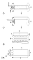
- 2A to 2D are diagrams for explaining an example of a foil tab.
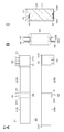
- 3A to 3C are diagrams for explaining the first embodiment.
- 4A to 4C are diagrams for explaining the second embodiment.
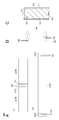
- 5A to 5C are diagrams for explaining the third embodiment.
- 6A to 6C are diagrams for explaining the fourth embodiment.
- 7A to 7C are diagrams for explaining the fifth embodiment.
- 8A to 8C are diagrams for explaining Comparative Example 1.
- 9A to 9C are diagrams for explaining the first modification.
- 10A to 10C are diagrams for explaining the second modification.
- 11A to 11C are diagrams for explaining the modified example 3.
- 12A to 12C are diagrams for explaining the modified example 4.
- FIG. 13A to 13C are diagrams for explaining the modified example 5.
- 14A to 14C are diagrams for explaining the modification 6.
- 15A to 15C are diagrams for explaining the modified example 7.
- 16A to 16C are diagrams for explaining the modified example 8.
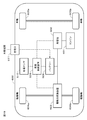
- FIG. 17 is a connection diagram used for explaining a battery pack as an application example of the present invention.
- FIG. 18 is a connection diagram used for explaining a power tool as an application example of the present invention.
- FIG. 19 is a connection diagram used for explaining an electric vehicle as an application example of the present invention.
- a cylindrical lithium ion battery will be described as an example as the secondary battery.
- a battery other than the lithium ion battery or a battery other than the cylindrical shape may be used.
- FIG. 1 is a schematic cross-sectional view of the lithium ion battery 1.
- the lithium ion battery 1 is, for example, a cylindrical lithium ion battery 1 in which an electrode winding body 20 is housed inside a battery can 11.
- the lithium ion battery 1 includes a pair of insulating plates 12 and 13 and an electrode winding body 20 inside a cylindrical battery can 11.
- the lithium ion battery 1 may further include one or more of one or more of a heat-sensitive resistor (Positive Temperature Coefficient Thermal-Resistor or PTC), a reinforcing member, and the like inside the battery can 11.
- a heat-sensitive resistor Positive Temperature Coefficient Thermal-Resistor or PTC
- PTC Heat-sensitive resistor
- the battery can 11 is mainly a member for accommodating the electrode winding body 20.
- the battery can 11 is a cylindrical container in which one end is opened and the other end is closed. That is, the battery can 11 has an open end portion (open end portion 11N).
- the battery can 11 contains any one or more of metal materials such as iron, aluminum and alloys thereof. However, on the surface of the battery can 11, any one or more of the metal materials such as nickel may be plated.
- the insulating plates 12 and 13 are sheet-like members having a surface substantially perpendicular to the winding axis direction (vertical direction in FIG. 1) of the electrode winding body 20.
- the insulating plates 12 and 13 are arranged so as to sandwich the electrode winding body 20 with each other.
- PET polyethylene terephthalate
- PP polypropylene
- bakelite includes paper bakelite and cloth bakelite, which are produced by applying a phenol resin to paper or cloth and then heating it.
- a battery lid 14 and a safety valve mechanism 30 are crimped to the open end portion 11N of the battery can 11 at a bent portion 11P via a gasket 15, and a caulking structure 11R (crimp structure) is formed.
- the battery can 11 is sealed in a state where the electrode winding body 20 and the like are housed inside the battery can 11.
- the battery lid 14 is a member that closes the open end 11N of the battery can 11 in a state where the electrode winding body 20 or the like is housed inside the battery can 11.
- the battery lid 14 contains the same material as the material for forming the battery can 11.
- the central region of the battery lid 14 projects in the vertical direction in FIG.
- a region (peripheral region) of the battery lid 14 other than the central region is in contact with the safety valve mechanism 30 via the PTC element 16.
- the gasket 15 is mainly interposed between the bent portion 11P (also referred to as a crimp portion) of the battery can 11 and the battery lid 14, thereby forming a gap between the bent portion 11P and the battery lid 14. It is a member to be sealed. For example, asphalt or the like may be applied to the surface of the gasket 15.
- Gasket 15 contains an insulating material.
- the type of the insulating material is not particularly limited, but is a polymer material such as polybutylene terephthalate (PBT) and polyp-mouth pyrene (PP). This is because the gap between the bent portion 11P and the battery lid 14 is sufficiently sealed while the battery can 11 and the battery lid 14 are electrically separated from each other.
- PBT polybutylene terephthalate
- PP polyp-mouth pyrene
- the safety valve mechanism 30 mainly releases the internal pressure of the battery can 11 by releasing the sealed state of the battery can 11 as necessary when the internal pressure (internal pressure) of the battery can 11 rises.
- the cause of the increase in the internal pressure of the battery can 11 is gas generated due to the decomposition reaction of the electrolytic solution during charging / discharging.
- a band-shaped positive electrode 21 and a band-shaped negative electrode 22 are wound in a spiral shape with a separator 23 interposed therebetween, and are housed in a battery can 11 in a state of being impregnated with an electrolytic solution.
- the positive electrode 21 and the negative electrode 22 have a positive electrode active material layer and a negative electrode active material layer formed on one or both sides of the positive electrode foil and the negative electrode foil, respectively.
- the material of the positive electrode foil is a metal foil containing aluminum or an aluminum alloy.
- the material of the negative electrode foil is a metal foil containing nickel, nickel alloy, copper and copper alloy.
- the separator 23 is a porous and insulating film that electrically insulates the positive electrode 21 and the negative electrode 22 while allowing the movement of lithium ions.
- a space (central space 20C) created when the positive electrode 21, the negative electrode 22 and the separator 23 are wound is provided at the center of the electrode winding body 20, and the center pin 24 is inserted into the central space 20C. (Fig. 1). However, the center pin 24 can be omitted.
- the positive electrode lead 25 is connected to the positive electrode 21, and the negative electrode lead 26 is connected to the negative electrode 22 (FIG. 1).
- the positive electrode lead 25 contains a conductive material such as aluminum.
- the positive electrode lead 25 is connected to the safety valve mechanism 30 and is electrically connected to the battery lid 14 via the PTC element.
- the negative electrode lead 26 contains a conductive material such as nickel.
- the negative electrode lead 26 is electrically connected to the battery can 11.
- the positive electrode active material layer contains at least a positive electrode material (positive electrode active material) capable of occluding and releasing lithium, and may further contain a positive electrode binder, a positive electrode conductive agent, and the like.
- the positive electrode material is preferably a lithium-containing compound (for example, a lithium-containing composite oxide and a lithium-containing phosphoric acid compound).
- the lithium-containing composite oxide has, for example, a layered rock salt type or spinel type crystal structure.
- the lithium-containing phosphoric acid compound has, for example, an olivine-type crystal structure.
- the positive electrode binder contains synthetic rubber or a polymer compound.
- Synthetic rubbers include styrene-butadiene rubbers, fluororubbers and ethylene propylene dienes.
- the polymer compound is polyvinylidene fluoride (PVdF), polyimide and the like.
- the positive electrode conductive agent is a carbon material such as graphite, carbon black, acetylene black or ketjen black.
- the positive electrode conductive agent may be a metal material or a conductive polymer.
- the surface of the negative electrode foil is preferably roughened. This is because the so-called anchor effect improves the adhesion of the negative electrode active material layer to the negative electrode foil.
- a method of roughening for example, there is a method of forming fine particles by using an electrolytic method and providing unevenness on the surface of the negative electrode foil.
- the copper foil produced by the electrolytic method is generally called an electrolytic copper foil.
- the negative electrode active material layer contains at least a negative electrode material (negative electrode active material) capable of occluding and releasing lithium, and may further contain a negative electrode binder, a negative electrode conductive agent, and the like.
- the negative electrode material includes, for example, a carbon material. This is because a high energy density can be stably obtained because the change in the crystal structure during the occlusion and release of lithium is very small. Further, since the carbon material also functions as a negative electrode conductive agent, the conductivity of the negative electrode active material layer is improved.
- the carbon material is graphitizable carbon, non-graphitizable carbon, graphite, low crystalline carbon, or amorphous carbon.
- the shape of the carbon material is fibrous, spherical, granular or scaly.
- the negative electrode material may include, for example, a metal-based material.
- metal-based materials include Li (lithium), Si (silicon), Sn (tin), Al (aluminum), Zn (zinc), and Ti (titanium).
- Metallic elements form compounds, mixtures or alloys with other elements, such as silicon oxide (SiO x (0 ⁇ x ⁇ 2)), silicon carbide (SiC) or carbon-silicon alloys. , Lithium titanate (Li 4 Ti 5 O 12 ).
- the negative electrode material preferably contains a silicon-containing compound such as silicon oxide or a silicon alloy, or a simple substance of silicon.
- a silicon-containing compound such as silicon oxide or a silicon alloy, or a simple substance of silicon.
- the content of silicon oxide contained in the negative electrode active material layer is preferably 5 wt% or more and 20 wt% or less. This is because if the content is too low, the effect of increasing the capacity cannot be obtained, and if it is too high, silicon expands and impairs the battery characteristics. The same applies to the content of silicon alloys and simple substances of silicon.
- the open circuit voltage that is, the battery voltage
- the same positive electrode active material is used as compared with the case where the open circuit voltage at the time of full charge is low. Also, the amount of lithium released per unit mass increases. This gives a high energy density.
- the separator 23 is a porous film containing a resin, and may be a laminated film of two or more kinds of porous films.
- the resin is polypropylene, polyethylene or the like.
- the separator 23 may have a porous film as a base material layer and may contain a resin layer on one side or both sides thereof. This is because the adhesion of the separator 23 to each of the positive electrode 21 and the negative electrode 22 is improved, so that the distortion of the electrode winding body 20 is suppressed.
- the resin layer contains a resin such as PVdF.
- a solution in which the resin is dissolved in an organic solvent is applied to the base material layer, and then the base material layer is dried. After immersing the base material layer in the solution, the base material layer may be dried.
- the resin layer contains inorganic particles or organic particles from the viewpoint of improving heat resistance and battery safety.
- the types of inorganic particles are aluminum oxide, aluminum nitride, aluminum hydroxide, magnesium hydroxide, boehmite, talc, silica, mica, and the like.
- a surface layer containing inorganic particles as a main component which is formed by a sputtering method, an ALD (atomic layer deposition) method, or the like, may be used.
- the electrolytic solution contains a solvent and an electrolyte salt, and may further contain additives and the like, if necessary.
- the solvent is a non-aqueous solvent such as an organic solvent, or water.
- An electrolytic solution containing a non-aqueous solvent is called a non-aqueous electrolytic solution.
- the non-aqueous solvent is a cyclic carbonate ester, a chain carbonate ester, a lactone, a chain carboxylic acid ester, a nitrile (mononitrile), or the like.
- a typical example of the electrolyte salt is a lithium salt, but a salt other than the lithium salt may be contained.
- Lithium salts include lithium hexafluorophosphate (LiPF 6 ), lithium tetrafluoroborate (LiBF 4 ), lithium perchlorate (LiClO 4 ), lithium methanesulfonate (LiCH 3 SO 3 ), and trifluoromethanesulfonic acid.
- Lithium (LiCF 3 SO 3 ) dilithium hexafluorosilicate (Li 2 SF 6 ), etc.
- These salts can be mixed and used, and among them, it is preferable to use a mixture of LiPF 6 and LiBF 4 from the viewpoint of improving battery characteristics.
- the content of the electrolyte salt is not particularly limited, but is preferably 0.3 mol / kg to 3 mol / kg with respect to the solvent.
- the positive electrode mixture is prepared by mixing the positive electrode active material, the positive electrode binder and the positive electrode conductive agent. Subsequently, the positive electrode mixture is dispersed in an organic solvent to prepare a pace-shaped positive electrode mixture slurry. Subsequently, a positive electrode mixture slurry is applied to both sides of the positive electrode foil and then dried to form a positive electrode active material layer. Subsequently, while heating the positive electrode active material layer, the positive electrode active material layer is compression-molded using a roll press machine to obtain a positive electrode 21.
- the positive electrode lead 25 and the negative electrode lead 26 are connected to the positive electrode foil and the negative electrode foil by a welding method, respectively. Subsequently, after laminating the positive electrode 21 and the negative electrode 22 via the separator 23, they are wound and a fixing tape is attached to the outermost peripheral surface of the separator 23 to form the electrode winding body 20.
- the electrode winding body 20 is housed inside the battery can 11 with the insulator in contact with the exposed side of the negative electrode winding body 20 of the electrode winding body 20, and the can bottom and the negative electrode lead 26 are held together. Connect using the welding method. Next, an insulator is also placed on the side where the positive electrode lead 25 of the electrode winding body 20 is exposed, and one end of the positive electrode lead 25 is connected to the safety valve mechanism 30 by a welding method.
- the battery can 11 is processed using a beading processing machine (grooving processing machine) to form a dent in the battery can 11.
- the electrolytic solution is injected into the inside of the battery can 11 to impregnate the electrode winding body 20.
- the battery lid 14 and the safety valve mechanism 30 are housed together with the gasket 15 inside the battery can 11.
- the caulking structure 11R is formed by caulking the battery lid 14 and the safety valve mechanism 30 at the open end 11N of the battery can 11 via the gasket 15.
- the present invention will be specifically described using the battery 1 produced as described above based on examples of the internal resistance of the battery, the short circuit occurrence rate and the buckling occurrence rate after the low temperature cycle test and the drop test.
- the present invention is not limited to the examples described below.
- the battery size was 18650 (diameter 18 mm, height 65 mm), and the rated capacity was 3000 mAh.
- the material of the positive electrode foil 21A was Al, and the thickness was 0.015 mm.
- the material of the negative electrode foil 22A was Cu, and the thickness was 0.015 mm.
- the separator 23 was made of biaxially stretched polyethylene and had a thickness of 0.010 mm.
- the negative electrode active material contains carbon and silicon. Specifically, the negative electrode active material contains carbon as a main material, and the content of silicon oxide is 15 wt% in Examples and Comparative Examples.
- the positive electrode foil tab 35 and the like shown below correspond to the positive electrode lead 25 in FIG. 1, and the negative electrode tab 52 and the like correspond to the negative electrode lead 26 in FIG.
- the positive electrode foil tab 35 and the negative electrode foil tab 32 will be described as examples.
- the region in which the surface of the positive electrode foil 21A is coated with the positive electrode active material layer is referred to as the positive electrode active material coated portion 21B, and the uncoated region is referred to as the positive electrode active material uncoated portion 21C.
- the region where the surface of the negative electrode foil 22A is coated with the negative electrode active material layer is referred to as the negative electrode active material coated portion 22B, and the uncoated region is referred to as the negative electrode active material uncoated portion 22C.
- the positive electrode 21 or the negative electrode 22 has a positive electrode foil tab 31 or a negative electrode foil tab 32 on the winding start side.
- the foil tab 32 of the negative electrode has a flat plate shape and includes a plate-shaped portion 39 and a comb tooth portion 34.
- the plate-shaped portion 39 of the foil tab 32 has a width of 24 mm, which is larger than that of the conventional tab, and plays a role of collecting current from the negative electrode 22. It has a comb tooth portion 34 at the end of the foil tab 32.
- the comb tooth portion 34 has a comb shape in which one band-shaped protrusion has a width of 3 mm and a length of 5 mm.
- the intervals between the band-shaped protrusions of the comb tooth portion 34 in FIG. 2A are 7 mm and 8 mm from the winding start side, which are not constant values.
- the spacing between the band-shaped protrusions of the comb tooth portion 34 is such that the width of the band-shaped protrusions that overlap due to a lap delay during winding overlaps within approximately ⁇ 1 mm, and there is no problem in welding with the can bottom or the safety valve from the winding start side. It is designed to grow gradually.
- the spacing between the band-shaped protrusions of the foil tab 32 is set to gradually increase from the winding start side so that the band-shaped protrusions of the comb tooth portion 34 form one unified shape when the foil tab 32 is wound. ing. As shown in FIG.
- the plate-shaped portion 39 of the foil tab 32 of the negative electrode is formed on the active material uncoated portion 22C of the negative electrode, which is the winding start side of the negative electrode 22, at three welding points 61 (FIG. It is joined at the part with the dot pattern inside).
- the foil tab 32 is arranged so that the comb tooth portion 34 protrudes from the negative electrode 22. Even in the case of the positive electrode foil tab 31, it is possible to adopt the same configuration as the negative electrode foil tab 32.
- the foil tab 32 is wound together with the negative electrode 22, and as shown in FIG. 2C, the comb tooth portions 34 of the foil tab 32 are offset by one round and overlapped to be put together at one place, whereby one of the foil tabs 32. It is referred to as a connection portion 42.
- the connection portion 42 is joined to the bottom of the battery can 11.
- the comb tooth portion 34 of the foil tab 32 of FIGS. 2A and 2B has three band-shaped protrusions.
- the plate-shaped portion 39 of the foil tab 32 is wound around two turns, and the connecting portion 42 has three band-shaped protrusions. It has an overlapping structure.
- the wound foil tab 32 is a reinforcing material for the inner peripheral portion of the electrode winding body 20, and can prevent buckling and deformation of the inner peripheral portion of the electrode winding body 20 when the battery 1 is charged and discharged.
- the comb tooth portion of the negative electrode foil tab 32 may be divided into, for example, four, six or more comb tooth portions 34, in which case, as shown in FIG. 2D, the foil tab 32 is wound.
- the comb tooth portions 34 of the above are overlapped together at two places to form two connecting portions 42A and 42B facing each other.
- relatively long band-shaped protrusions and relatively short band-shaped protrusions are alternately arranged on the comb tooth portion 34 of the foil tab 32 of the negative electrode (not shown), and when wound, the long band-shaped protrusions and the short band-shaped protrusions are arranged alternately.
- the foil tab 32 has a relatively long connection portion 42A and a relatively short connection portion 42B.
- the positive electrode foil tab 31 has the same shape as the negative electrode foil tab 32, except that the length of the comb tooth portion 33 is relatively large. Similarly, the comb tooth portion 33 protrudes from the positive electrode 21 and is wound together with the positive electrode 21 so that the plurality of band-shaped projections are one or two connecting portions 41. When there are two connecting portions 41, there is no particular difference in the lengths of the two connecting portions 41.
- the plate-shaped portion of the foil tab 31 is joined by welding at the active material uncoated portion 21C of the positive electrode, which is the winding start side of the positive electrode.
- the wound foil tab 31 is a reinforcing material for the inner peripheral portion of the electrode winding body 20, and can prevent buckling and deformation of the inner peripheral portion of the electrode winding body 20 when the battery 1 is charged and discharged.
- the thickness of the foil tabs 31 and 32 is 0 because the foil tabs 31 and 32 need to have a thickness as a reinforcing material for the inner peripheral portion of the electrode winding body 20 and due to structural restrictions in the battery can 11. It is preferably 020 mm or more and 0.100 mm or less. More preferably, the thickness of the foil tabs 31 and 32 is 0.030 mm or more and 0.080 mm or less.
- the material of the foil tab 32 of the negative electrode is preferably any one of copper, copper-nickel alloy, nickel, zinc, copper-zinc alloy, copper-zinc-nickel alloy, or a composite material thereof. Further, the number of turns of the foil tab 32 is preferably 1 or more and 4 or less.
- Examples of the material of the foil tab 31 of the positive electrode include aluminum, titanium, and stainless steel (SUS).
- SUS304 dissolves after heating and aging in a 4.2 V system in which an LCO positive electrode or an NCA positive electrode is used, but is insoluble in a 3.6 V system in which a LiFePO 4 positive electrode or the like is used.
- SUS316 is insoluble even in a 4.2V system in which an LCO positive electrode or an NCA positive electrode is used after heating and aging.
- a material can be appropriately selected and used according to the battery voltage.
- the positive electrode 21 of the embodiment shown below has a positive electrode foil tab 35 between the winding start side and the winding end side.
- the foil tab 35 of the positive electrode has, for example, a flat plate shape, and is composed of a plate-shaped portion and a comb tooth portion 36.
- the plate-shaped portion of the foil tab 35 has a larger width than the conventional tab and plays a role of collecting current from the positive electrode.
- the foil tab 35 has a comb tooth portion 36 composed of two band-shaped protrusions at the end.
- the comb tooth portion 36 of the foil tab 35 has a comb shape in which one band-shaped protrusion has a width of 6 mm and a length of 7 mm. The distance between the two strips is about 20 mm, and the strips of the comb tooth portion 36 are designed to form a single unit when the foil tab 35 is wound together with the positive electrode 21.
- the plate-shaped portion of the foil tab 35 of the positive electrode is joined to the active material uncoated portion 21C of the positive electrode, which is a substantially intermediate position of the positive electrode 21, by welding. At this time, the foil tab 35 is arranged so that the comb tooth portion 36 protrudes from the positive electrode 21.
- the material of the foil tab 35 of the positive electrode the same material as that of the foil tab 31 can be used.
- the thickness of the foil tab 35 is preferably 0.020 mm or more and 0.100 mm or less. More preferably, the thickness of the foil tab 35 is 0.030 mm or more and 0.080 mm or less.
- the foil tab 35 is wound together with the positive electrode 21, and the band-shaped protrusions of the comb tooth portions 36 of the foil tab 35 are offset by one circumference and overlapped to form one connection portion 43 of the foil tab 35.
- the connection portion 43 is joined to the safety valve mechanism 30.
- the comb tooth portion 36 of the foil tab 35 has two strip-shaped protrusions
- the plate-shaped portion of the foil tab 35 is wound around one circumference
- the connecting portion 43 has a structure in which two strip-shaped protrusions are overlapped.
- the wound foil tab 35 is a reinforcing material for the inner peripheral portion of the electrode winding body 20, and can prevent buckling and deformation of the inner peripheral portion of the electrode winding body 20 when the battery 1 is charged and discharged.
- the thickness of the foil tab 35 at the substantially intermediate position of the positive electrode 21 was 0.05 mm, the width of the band-shaped protrusion of the comb tooth portion 36 was 6 mm, and the material was Al.
- the active material uncoated portion 21C of the positive electrode to which the foil tab 35 and the foil tab 35 joined at a substantially intermediate position of the positive electrode 21 was covered with an insulating tape 51.
- the thickness of the tab 52 at the substantially intermediate position of the negative electrode 22 was 0.08 mm, the width was 3 mm, and the material was Cu.
- the active material uncoated portion 22C of the negative electrode to which the tab 52 and the tab 52 bonded to each other at a substantially intermediate position of the negative electrode 22 was covered with an insulating tape 51.
- the thickness of the foil tab 31 on the winding start side of the positive electrode 21 is 0.05 mm
- the width of the band-shaped protrusion of the comb tooth portion 33 is 3 mm
- the material is Al. ..
- the active material uncoated portion 21C of the positive electrode to which the foil tab 31 and the foil tab 31 on the winding start side of the positive electrode 21 were joined was covered with an insulating tape 51.
- the thickness of the foil tab 32 on the winding start side of the negative electrode 22 was 0.04 mm
- the width of the band-shaped protrusion of the comb tooth portion 34 was 3 mm
- the material was Cu.
- the thickness of the tab 55 at the substantially intermediate position of the positive electrode 21 was 0.1 mm, the width was 6 mm, and the material was Al.
- the thickness of the tab 54 on the winding start side of the negative electrode 22 was 0.08 mm, the width was 3 mm, and the material was CuNi.
- the thickness of the tab 53 on the winding end side of the negative electrode 22 was 0.08 mm, the width was 3 mm, and the material was CuNi.
- the thickness of the tabs 52, 53, 54, 55, the thickness of the foil tab 35, and the thickness of the foil tabs 31, 32 were measured using a micrometer (MDC-25MX manufactured by Mitutoyo).
- 3A to 8A (A in each of FIGS. 3 to 8) show a schematic view of the positive electrode 21 before winding on the upper side of each figure, and a schematic view of the negative electrode 22 before winding on the lower side of each figure.
- the right side of each figure is the winding start side, and the left side of each figure is the winding end side.
- 3B to 8B (B in each of FIGS. 3 to 8) show schematic views of the electrode winding body 20 after winding the positive electrode 21 and the negative electrode 22 of FIGS. 3A to 8A together with the separator 23, respectively.
- the upper side of each figure is the battery lid 14 side, and the lower side of each figure is the can bottom side of the battery can 11.
- 3C to 8C (C in each of FIGS. 3 to 8) are schematic views when the electrode winding body 20 of FIGS. 3B to 8B is housed in the battery can 11 and used as the battery 1.
- Example 1 As shown in FIG. 3A, the foil tab 35 was arranged at a substantially intermediate position of the positive electrode 21, and the tab 52 was arranged at a substantially intermediate position of the negative electrode 22.
- the comb tooth portion 36 of the foil tab 35 was composed of two band-shaped protrusions.
- FIG. 3B the positive electrode 21 and the negative electrode 22 are overlapped with each other via the separator 23, and the two strip-shaped protrusions of the comb tooth portion 36 are overlapped and wound so as to be combined with one connection portion 43, and the tab of the negative electrode is formed.
- the number of turns of 52 was set to one lap.
- the material of the foil tab 35 was Al, and the material of the tab 52 was Cu.
- FIG. 3C the electrode winding body 20 to which the foil tab 35 and the tab 52 are joined is arranged in the battery can 11.
- the content of silicon oxide contained in the negative electrode active material was set to 15 wt%.
- Example 2 As shown in FIG. 4A, the foil tab 35 was arranged at a substantially intermediate position of the positive electrode 21, and the foil tab 31 was arranged on the winding start side of the positive electrode 21.
- the comb tooth portion 36 of the foil tab 35 was composed of two band-shaped protrusions
- the comb tooth portion 33 of the foil tab 31 was composed of six band-shaped protrusions.
- the tab 52 was arranged at a substantially intermediate position of the negative electrode 22, and the foil tab 32 was arranged on the winding start side of the negative electrode 22.
- the comb tooth portion 34 of the foil tab 32 was composed of six band-shaped protrusions. As shown in FIG.
- the positive electrode 21 and the negative electrode 22 are overlapped with each other via the separator 23, and the foil tab 35 is wound so that the two band-shaped protrusions of the comb tooth portion 36 are overlapped and combined into one connection portion 43.
- the number of turns of the positive electrode foil tab 35 was set to one turn.
- the six band-shaped protrusions of the comb tooth portions 33 and 34 are overlapped with each other and put together into the two connecting portions 41 and 41 and the two connecting portions 42A and 42B.
- the number of turns of the positive electrode foil tab 31 was set to 2.5 turns
- the number of turns of the negative electrode foil tab 32 was set to 2.5 turns.
- the electrode winding body 20 to which the foil tab 35, the tab 52, and the foil tabs 31 and 32 are joined is arranged in the battery can 11.
- the content of silicon oxide contained in the negative electrode active material was set to 15 wt%.
- Example 3 As shown in FIG. 5A, the foil tab 35 was arranged at a substantially intermediate position of the positive electrode 21, and the foil tab 31 was arranged on the winding start side of the positive electrode 21.
- the comb tooth portion 36 of the foil tab 35 was composed of two band-shaped protrusions
- the comb tooth portion 33 of the foil tab 31 was composed of four band-shaped protrusions.
- the tab 52 was arranged at a substantially intermediate position of the negative electrode 22, and the foil tab 32 was arranged on the winding start side of the negative electrode 22.
- the comb tooth portion 34 of the foil tab 32 was composed of four band-shaped protrusions. As shown in FIG.
- the positive electrode 21 and the negative electrode 22 are overlapped with each other via the separator 23, and the foil tab 35 is wound so that the two band-shaped protrusions of the comb tooth portion 36 are overlapped and combined into one connection portion 43.
- the number of turns of the positive electrode foil tab 35 was set to one turn.
- the four strips of the comb teeth 33 and 34 are overlapped with each other and put together into the two connecting portions 41 and 41 and the two connecting portions 42A and 42B.
- the number of turns of the positive electrode foil tab 31 was 1.5 turns
- the number of turns of the negative electrode foil tab 32 was 1.5 turns.
- the electrode winding body 20 to which the foil tab 35, the tab 52, and the foil tabs 31 and 32 are joined is arranged in the battery can 11.
- the content of silicon oxide contained in the negative electrode active material was set to 15 wt%.
- the foil tab 35 was arranged at a substantially intermediate position of the positive electrode 21, and the foil tab 31 was arranged on the winding start side of the positive electrode 21.
- the comb tooth portion 36 of the foil tab 35 was composed of two band-shaped protrusions
- the comb tooth portion 33 of the foil tab 31 was composed of three band-shaped protrusions.
- the tab 52 was arranged at a substantially intermediate position of the negative electrode 22, and the foil tab 32 was arranged on the winding start side of the negative electrode 22.
- the comb tooth portion 34 of the foil tab 32 was composed of three band-shaped protrusions. As shown in FIG.
- the positive electrode 21 and the negative electrode 22 are overlapped with each other via the separator 23, and the foil tab 35 is wound so that the two strips of the comb tooth portion 36 are overlapped and combined into one connection portion 43.
- the number of turns of the positive electrode foil tab 35 was set to one turn.
- the three strips of the comb teeth 33 and 34 are overlapped with each other and wound so as to be integrated into one connecting portion 41 and one connecting portion 42.
- the number of turns of the positive electrode foil tab 31 was set to 2 turns
- the number of turns of the negative electrode foil tab 32 was set to 2 turns.
- the electrode winding body 20 to which the foil tab 35, the tab 52, and the foil tabs 31 and 32 are joined is arranged in the battery can 11.
- the content of silicon oxide contained in the negative electrode active material was set to 15 wt%.
- Example 5 As shown in FIG. 7A, the foil tab 35 was arranged at a substantially intermediate position of the positive electrode 21, and the foil tab 31 was arranged on the winding start side of the positive electrode 21.
- the comb tooth portion 36 of the foil tab 35 was composed of two band-shaped protrusions
- the comb tooth portion 33 of the foil tab 31 was composed of two band-shaped protrusions.
- the tab 52 was arranged at a substantially intermediate position of the negative electrode 22, and the foil tab 32 was arranged on the winding start side of the negative electrode 22.
- the comb tooth portion 34 of the foil tab 32 was composed of two band-shaped protrusions. As shown in FIG.
- the positive electrode 21 and the negative electrode 22 are overlapped with each other via the separator 23, and the foil tab 35 is wound so that the two band-shaped protrusions of the comb tooth portion 36 are overlapped and combined into one connection portion 43.
- the number of turns of the positive electrode foil tab 35 was set to one turn.
- the two strips of the comb teeth 33 and 34 are overlapped with each other and wound so as to be combined into one connecting portion 41 and one connecting portion 42.
- the number of turns of the positive electrode foil tab 31 was set to one turn, and the number of turns of the negative electrode foil tab 32 was set to one turn.
- the electrode winding body 20 to which the foil tab 35, the tab 52, and the foil tabs 31 and 32 are joined is arranged in the battery can 11.
- the content of silicon oxide contained in the negative electrode active material was set to 15 wt%.
- the tab 55 is arranged at a substantially intermediate position of the positive electrode 21, the tab 54 is arranged on the winding start side of the negative electrode 22, and the tab 53 is arranged on the winding end side of the negative electrode 22.
- the positive electrode 21 and the negative electrode 22 were overlapped and wound via the separator 23.
- the electrode winding body 20 to which the tabs 53, 54, 55 are joined is arranged in the battery can 11.
- the content of silicon oxide contained in the negative electrode active material was set to 15 wt%.
- the internal resistance of the battery was obtained, the short circuit occurrence rate was obtained by performing a drop test after the low temperature cycle test, and the buckling occurrence rate was obtained by CT imaging. Evaluation was performed.
- the internal resistance of the battery, low temperature cycle test, drop test and CT imaging are as follows. ⁇ Battery internal resistance> The internal resistance of the battery was determined from the result of AC impedance measurement at a frequency of 1 kHz.
- ⁇ CT shooting> After the drop test after the low temperature cycle, the inner peripheral portion of the electrode winding body was observed using an X-ray CT imaging device, and the percentage of the battery causing buckling was taken as the buckling occurrence rate. The number of tests was 10.
- Examples 1 to 5 the short circuit occurrence rate and the buckling occurrence rate were 0% or 10%, and the comprehensive evaluation was OK, whereas in Comparative Example 1, these were high values and the comprehensive evaluation was NG. Met.
- the examples 1 and Comparative Example 1 having no foil tabs are used. The internal resistance of the battery was lower than that.
- the inner peripheral portion of the electrode winding body was not distorted and was kept in a perfect circle, whereas in Comparative Example 1, the inner peripheral portion of the electrode winding body was distorted and the perfect circle was formed. I could't keep it.
- the foil tab 35 of the positive electrode is provided between the winding start side and the winding end side of the positive electrode (substantially intermediate position of the positive electrode), and the foil tab 35 has a comb tooth portion 36 protruding from the positive electrode 21.
- the comb tooth portion 36 is used as the connection portion 43 of the electrode winding body 20, it can be determined that the battery 1 does not cause buckling or internal short circuit even if it is repeatedly charged and discharged.
- the tab 56 is further arranged at a position of about 1/3 of the total length from the winding end side to the winding start side of the positive electrode 21, and the thickness of the tab 56 is set to 0.1 mm.
- the width was 5 mm and the material was aluminum.
- the active material uncoated portion 21C of the positive electrode to which the tab 56 and the tab 56 joined at a substantially intermediate position of the positive electrode 21 was covered with an insulating tape 51.
- the thickness of the tab 56 was measured using a micrometer (MDC-25MX manufactured by Mitutoyo).
- the foil tab 37 shown in the modified example is the same as the foil tab 35 except for the spacing between the band-shaped protrusions of the comb tooth portion 38.
- 9A to 16A (A in each of FIGS. 9 to 16) show a schematic view of the positive electrode 21 before winding on the upper side of each figure, and a schematic view of the negative electrode 22 before winding on the lower side of each figure.
- the right side of each figure is the winding start side, and the left side of each figure is the winding end side.
- 9B to 16B (B in each of FIGS. 9 to 16) show schematic views of the electrode winding body 20 after winding the positive electrode 21 and the negative electrode 22 of FIGS. 9A to 16A together with the separator, respectively.
- the upper side of each figure is the battery lid 14 side, and the lower side of each figure is the can bottom side of the battery can 11.
- 9C to 16C (C in each of FIGS. 9 to 16) are schematic views when the electrode winding body 20 of FIGS. 9B to 16B is housed in the battery can 11 and used as the battery 1.
- the negative electrodes of Modifications 1 to 4 have a structure in which a tab 53 is added to the negative electrodes of Examples 2 to 5 and a tab 53 is further added to the winding end side of the negative electrode.
- FIG. 9 shows a modification 1 in which a tab 53 is added to the second embodiment
- FIG. 10 shows a modification 2 in which the tab 53 is added to the third embodiment
- FIG. 11 shows a modification in which the tab 53 is added to the fourth embodiment.
- the modified example 3 is shown
- FIG. 12 shows the modified example 4 in which the tab 53 is added to the fifth embodiment.
- the tab 53 of the negative electrode added in the modification 1 to the modification 4 was welded to the bottom of the battery can together with the connection portion 42 and the like.
- the foil tab 37 is arranged at a position of about 1/3 of the total length from the winding start side of the positive electrode 21 toward the winding end side, and winding starts from the winding end side of the positive electrode 21.
- the tab 56 was arranged at a position of about 1/3 of the total length toward the side, and the foil tab 31 was arranged on the winding start side of the positive electrode 21.
- the comb tooth portion 38 of the foil tab 37 was composed of two band-shaped protrusions, and the comb tooth portion 33 of the foil tab 31 was composed of six band-shaped protrusions.
- the tab 52 is arranged at a position of about 1/3 of the total length from the winding start side of the negative electrode 22 toward the winding end side, the tab 53 is arranged on the winding end side of the negative electrode 22, and the winding start of the negative electrode 22 is started.
- the foil tab 32 was arranged on the side.
- the comb tooth portion 34 of the foil tab 32 was composed of six band-shaped protrusions. As shown in FIG. 13B, the positive electrode 21 and the negative electrode 22 are overlapped with each other via the separator 23, and the foil tab 37 is wound so that the two strips of the comb tooth portion 38 are overlapped and combined into one connection portion 45. The number of turns of the positive electrode foil tab 37 was set to one turn.
- each of the foil tab 31 and the foil tab 32 was made in the same manner as in the second embodiment.
- the electrode winding body 20 to which the foil tab 37, the tabs 52, 53, 56 and the foil tabs 31, 32 are joined is arranged in the battery can 11.
- Modifications 1 to 4 have the same buckling occurrence rate as in Examples 2 to 5, and it is predicted that the resistance value of the electrode winding body will be lower than in Examples 2 to 5.
- Modifications 5 to 8 have the same buckling occurrence rate as those of Examples 2 to 5, and it is predicted that the resistance value of the electrode winding body will be lower than that of Modifications 1 to 4.
- the size of battery 1 was 18650, but other sizes may be used.
- the rated capacity of the battery 1 is 3000 mAh, but other values may be used.
- the thicknesses of the positive electrode foil 21A, the negative electrode foil 22A, and the separator 23 do not have to be the above values.
- the number of band-shaped protrusions of the comb tooth portions 33, 34 is not limited to the examples, and may be other values.
- FIG. 17 is a block diagram showing a circuit configuration example when the battery 1 according to the embodiment or embodiment of the present invention is applied to the battery pack 300.
- the battery pack 300 includes a switch unit 304 including an assembled battery 301, a charge control switch 302a, and a discharge control switch 303a, a current detection resistor 307, a temperature detection element 308, and a control unit 310.
- the control unit 310 can control each device, perform charge / discharge control when abnormal heat generation occurs, and calculate or correct the remaining capacity of the battery pack 300.
- the positive electrode terminal 321 and the negative electrode terminal 322 are connected to the positive electrode terminal and the negative electrode terminal of the charger, respectively, and charging is performed. Further, when the electronic device connected to the battery pack 300 is used, the positive electrode terminal 321 and the negative electrode terminal 322 are connected to the positive electrode terminal and the negative electrode terminal of the electronic device, respectively, and discharge is performed.
- the assembled battery 301 is formed by connecting a plurality of secondary batteries 301a in series and / or in parallel.
- a case where six secondary batteries 301a are connected in two parallels and three series (2P3S) is shown as an example, but any connection method may be used.
- the temperature detection unit 318 is connected to a temperature detection element 308 (for example, a thermistor), measures the temperature of the assembled battery 301 or the battery pack 300, and supplies the measured temperature to the control unit 310.
- the voltage detection unit 311 measures the voltage of the assembled battery 301 and each of the secondary batteries 301a constituting the assembled battery 301, A / D converts the measured voltage, and supplies the measured voltage to the control unit 310.
- the current measuring unit 313 measures the current using the current detection resistor 307, and supplies the measured current to the control unit 310.
- the switch control unit 314 controls the charge control switch 302a and the discharge control switch 303a of the switch unit 304 based on the voltage and current input from the voltage detection unit 311 and the current measurement unit 313.
- the switch control unit 314 controls the switch unit 304 to be OFF when the voltage of any of the secondary batteries 301a becomes equal to or lower than the overcharge detection voltage or the overdischarge detection voltage, or when a large current suddenly flows. By sending a signal, overcharging, overdischarging, and overcurrent charging / discharging are prevented.
- the overcharge detection voltage is determined to be, for example, 4.20 V ⁇ 0.05 V
- the over discharge detection voltage is determined to be, for example, 2.4 V ⁇ 0.1 V.
- the charge control switch 302a or the discharge control switch 303a After the charge control switch 302a or the discharge control switch 303a is turned off, charging or discharging is possible only through the diode 302b or the diode 303b.
- semiconductor switches such as MOSFETs can be used.
- the parasitic diode of the MOSFET functions as the diodes 302b and 303b.
- the switch portion 304 is provided on the + side in FIG. 17, it may be provided on the ⁇ side.
- the memory 317 is composed of a RAM or a ROM, and includes, for example, an EPROM (ErasableProgrammableReadOnlyMemory) which is a non-volatile memory.
- the memory 317 stores in advance the numerical values calculated by the control unit 310, the battery characteristics in the initial state of each secondary battery 301a measured at the stage of the manufacturing process, and the like, and can be rewritten as appropriate. Further, by storing the fully charged capacity of the secondary battery 301a, the remaining capacity can be calculated in cooperation with the control unit 310.
- the battery 1 according to the embodiment or embodiment of the present invention described above can be mounted on a device such as an electronic device, an electric transport device, or a power storage device and used to supply electric power.
- Electronic devices include, for example, notebook computers, smartphones, tablet terminals, PDAs (personal digital assistants), mobile phones, wearable terminals, video movies, digital still cameras, electronic books, music players, headphones, game machines, pacemakers, hearing aids, etc. Examples include electric tools, televisions, lighting equipment, toys, medical equipment, and robots. Further, an electric transport device, a power storage device, a power tool, and an electric unmanned aerial vehicle, which will be described later, may also be included in the electronic device in a broad sense.
- Examples of electric transportation equipment include electric vehicles (including hybrid vehicles), electric motorcycles, electric assisted bicycles, electric buses, electric carts, unmanned transport vehicles (AGV), railway vehicles, and the like. It also includes electric passenger aircraft and electric unmanned aerial vehicles for transportation.
- the secondary battery according to the present invention is used not only as a power source for driving these, but also as an auxiliary power source, a power source for energy regeneration, and the like.
- Examples of the power storage device include a power storage module for commercial or household use, and a power supply for power storage for buildings such as houses, buildings, and offices, or for power generation equipment.
- the electric screwdriver 431 is provided with a motor 433 that transmits rotational power to the shaft 434 and a trigger switch 432 that is operated by the user. By operating the trigger switch 432, a screw or the like is driven into the object by the shaft 434.
- the battery pack 430 and the motor control unit 435 are housed in the lower housing of the handle of the electric screwdriver 431.
- the battery pack 430 the battery pack 300 described above can be used.
- the battery pack 430 is built into the electric screwdriver 431 or is removable.
- the battery pack 430 can be attached to the charging device in a state of being built in or removed from the electric driver 431.
- Each of the battery pack 430 and the motor control unit 435 is equipped with a microcomputer. Power is supplied from the battery pack 430 to the motor control unit 435, and charge / discharge information of the battery pack 430 is communicated between the two microcomputers.
- the motor control unit 435 can control the rotation / stop of the motor 433 and the rotation direction, and can further cut off the power supply to the load (motor 433 and the like) at the time of over-discharging.
- FIG. 19 schematically shows a configuration example of a hybrid vehicle (HV) that employs a series hybrid system.
- the series hybrid system is a vehicle that runs on a power driving force converter using the electric power generated by an engine-powered generator or the electric power temporarily stored in a battery.
- the hybrid vehicle 600 includes an engine 601, a generator 602, a power driving force converter 603 (DC motor or AC motor; hereinafter simply referred to as "motor 603"), drive wheels 604a, drive wheels 604b, wheels 605a, and wheels 605b. , Battery 608, vehicle control device 609, various sensors 610, and charging port 611 are mounted.
- the battery pack 300 of the present invention described above or a power storage module equipped with a plurality of batteries 1 of the present invention can be applied to the battery 608.
- the shape of the secondary battery is cylindrical, square or laminated.
- the motor 603 is operated by the electric power of the battery 608, and the rotational force of the motor 603 is transmitted to the drive wheels 604a and 604b.
- the rotational force of the engine 601 is transmitted to the generator 602, and the electric power generated by the generator 602 by the rotational force can be stored in the battery 608.
- the various sensors 610 control the engine speed via the vehicle control device 609, and control the opening degree of the throttle valve (not shown).
- the various sensors 610 include a speed sensor, an acceleration sensor, an engine speed sensor, and the like.
- the hybrid vehicle 600 When the hybrid vehicle 600 is decelerated by a braking mechanism (not shown), the resistance force at the time of deceleration is applied to the motor 603 as a rotational force, and the regenerative power generated by this rotational force is stored in the battery 608. Further, although not shown, an information processing device (for example, a battery remaining amount display device) that performs information processing related to vehicle control based on information related to the secondary battery may be provided.
- the battery 608 can receive electric power and store electricity by being connected to an external power source via the charging port 611 of the hybrid vehicle 600.
- Such an HV vehicle is referred to as a plug-in hybrid vehicle (PHV or PHEV).
- the present invention can also be applied to a parallel system in which an engine and a motor are used together, or a hybrid vehicle in which a series system and a parallel system are combined. Further, the present invention can be applied to an electric vehicle (EV or BEV) traveling only by a drive motor that does not use an engine, or a fuel cell vehicle (FCV).
- EV or BEV electric vehicle
- FCV fuel cell vehicle
Landscapes
- Chemical & Material Sciences (AREA)
- Chemical Kinetics & Catalysis (AREA)
- Electrochemistry (AREA)
- General Chemical & Material Sciences (AREA)
- Engineering & Computer Science (AREA)
- Manufacturing & Machinery (AREA)
- Materials Engineering (AREA)
- Inorganic Chemistry (AREA)
- Secondary Cells (AREA)
- Connection Of Batteries Or Terminals (AREA)
Abstract
La présente invention porte sur une batterie secondaire dans laquelle un corps d'électrode d'enroulement est logé dans un boîtier de batterie, le corps d'électrode d'enroulement ayant une structure dans laquelle une électrode positive en forme de bande et une électrode négative en forme de bande sont empilées, avec un séparateur interposé entre elles, et enroulées, l'électrode positive ayant des couches de matériau actif d'électrode positive sur les deux surfaces d'une feuille d'électrode positive en forme de bande; l'électrode négative ayant des couches de matériau actif d'électrode négative sur les deux surfaces d'une feuille d'électrode négative en forme de bande; le corps d'électrode d'enroulement ayant une languette de feuille d'électrode positive entre le côté de début d'enroulement et le côté de fin d'enroulement de l'électrode positive, et une languette d'électrode négative entre le côté de début d'enroulement de l'électrode négative et le côté de fin d'enroulement de l'électrode négative; et la languette de feuille d'électrode positive ayant une partie en forme de plaque liée sur le côté de début d'enroulement de l'électrode positive et une partie de dent de peigne faisant saillie à partir de l'électrode positive, la partie de dent de peigne étant conçue comme une partie de connexion du corps d'électrode d'enroulement.
Priority Applications (4)
| Application Number | Priority Date | Filing Date | Title |
|---|---|---|---|
| DE112021003195.3T DE112021003195T5 (de) | 2020-06-09 | 2021-05-24 | Sekuntärbatterie, elektronische einrichtung und elektrowerkzeug |
| CN202180041932.9A CN115699441A (zh) | 2020-06-09 | 2021-05-24 | 二次电池、电子设备以及电动工具 |
| JP2022530105A JP7396481B2 (ja) | 2020-06-09 | 2021-05-24 | 二次電池、電子機器及び電動工具 |
| US18/074,696 US20230102083A1 (en) | 2020-06-09 | 2022-12-05 | Secondary battery, electronic device, and electric tool |
Applications Claiming Priority (2)
| Application Number | Priority Date | Filing Date | Title |
|---|---|---|---|
| JP2020-100252 | 2020-06-09 | ||
| JP2020100252 | 2020-06-09 |
Related Child Applications (1)
| Application Number | Title | Priority Date | Filing Date |
|---|---|---|---|
| US18/074,696 Continuation US20230102083A1 (en) | 2020-06-09 | 2022-12-05 | Secondary battery, electronic device, and electric tool |
Publications (1)
| Publication Number | Publication Date |
|---|---|
| WO2021251121A1 true WO2021251121A1 (fr) | 2021-12-16 |
Family
ID=78846018
Family Applications (1)
| Application Number | Title | Priority Date | Filing Date |
|---|---|---|---|
| PCT/JP2021/019556 WO2021251121A1 (fr) | 2020-06-09 | 2021-05-24 | Batterie secondaire, dispositif électronique et outil électrique |
Country Status (5)
| Country | Link |
|---|---|
| US (1) | US20230102083A1 (fr) |
| JP (1) | JP7396481B2 (fr) |
| CN (1) | CN115699441A (fr) |
| DE (1) | DE112021003195T5 (fr) |
| WO (1) | WO2021251121A1 (fr) |
Cited By (1)
| Publication number | Priority date | Publication date | Assignee | Title |
|---|---|---|---|---|
| WO2022249989A1 (fr) * | 2021-05-25 | 2022-12-01 | 三洋電機株式会社 | Batterie secondaire à électrolyte non aqueux |
Citations (7)
| Publication number | Priority date | Publication date | Assignee | Title |
|---|---|---|---|---|
| JPS5770666U (fr) * | 1980-10-16 | 1982-04-28 | ||
| JPH07192717A (ja) * | 1993-12-24 | 1995-07-28 | Sony Corp | 非水電解液二次電池 |
| JP2009129553A (ja) * | 2007-11-20 | 2009-06-11 | Sony Corp | 電池 |
| JP2011070916A (ja) * | 2009-09-25 | 2011-04-07 | Toshiba Corp | 電極及び非水電解液電池 |
| WO2017159094A1 (fr) * | 2016-03-17 | 2017-09-21 | 日立オートモティブシステムズ株式会社 | Batterie rechargeable |
| WO2018180828A1 (fr) * | 2017-03-29 | 2018-10-04 | 三洋電機株式会社 | Batterie cylindrique |
| WO2019049485A1 (fr) * | 2017-09-11 | 2019-03-14 | パナソニックIpマネジメント株式会社 | Batterie secondaire |
-
2021
- 2021-05-24 DE DE112021003195.3T patent/DE112021003195T5/de active Pending
- 2021-05-24 JP JP2022530105A patent/JP7396481B2/ja active Active
- 2021-05-24 CN CN202180041932.9A patent/CN115699441A/zh active Pending
- 2021-05-24 WO PCT/JP2021/019556 patent/WO2021251121A1/fr active Application Filing
-
2022
- 2022-12-05 US US18/074,696 patent/US20230102083A1/en active Pending
Patent Citations (7)
| Publication number | Priority date | Publication date | Assignee | Title |
|---|---|---|---|---|
| JPS5770666U (fr) * | 1980-10-16 | 1982-04-28 | ||
| JPH07192717A (ja) * | 1993-12-24 | 1995-07-28 | Sony Corp | 非水電解液二次電池 |
| JP2009129553A (ja) * | 2007-11-20 | 2009-06-11 | Sony Corp | 電池 |
| JP2011070916A (ja) * | 2009-09-25 | 2011-04-07 | Toshiba Corp | 電極及び非水電解液電池 |
| WO2017159094A1 (fr) * | 2016-03-17 | 2017-09-21 | 日立オートモティブシステムズ株式会社 | Batterie rechargeable |
| WO2018180828A1 (fr) * | 2017-03-29 | 2018-10-04 | 三洋電機株式会社 | Batterie cylindrique |
| WO2019049485A1 (fr) * | 2017-09-11 | 2019-03-14 | パナソニックIpマネジメント株式会社 | Batterie secondaire |
Cited By (1)
| Publication number | Priority date | Publication date | Assignee | Title |
|---|---|---|---|---|
| WO2022249989A1 (fr) * | 2021-05-25 | 2022-12-01 | 三洋電機株式会社 | Batterie secondaire à électrolyte non aqueux |
Also Published As
| Publication number | Publication date |
|---|---|
| JP7396481B2 (ja) | 2023-12-12 |
| US20230102083A1 (en) | 2023-03-30 |
| JPWO2021251121A1 (fr) | 2021-12-16 |
| CN115699441A (zh) | 2023-02-03 |
| DE112021003195T5 (de) | 2023-04-20 |
Similar Documents
| Publication | Publication Date | Title |
|---|---|---|
| WO2021177149A1 (fr) | Batterie secondaire, dispositif électronique et outil électrique | |
| WO2021176906A1 (fr) | Batterie secondaire, dispositif électronique et outil électrique | |
| JP7047978B2 (ja) | 二次電池、電池パック、電子機器、電動工具及び電動車両 | |
| US20230102083A1 (en) | Secondary battery, electronic device, and electric tool | |
| US20220149445A1 (en) | Secondary battery, battery pack, electronic equipment, electric tool, and electric vehicle | |
| US20220255081A1 (en) | Secondary battery, electronic device, and power tool | |
| WO2021153231A1 (fr) | Batterie secondaire, appareil électronique, et outil électrique | |
| WO2021153230A1 (fr) | Batterie secondaire, dispositif électronique et outil électrique | |
| WO2021187259A1 (fr) | Batterie secondaire, dispositif électronique et outil électrique | |
| JP2021136233A (ja) | 二次電池、電子機器及び電動工具 | |
| WO2021193044A1 (fr) | Batterie secondaire, dispositif électronique et outil électrique | |
| WO2021106763A1 (fr) | Batterie secondaire, dispositif électronique et outil électrique | |
| WO2021177069A1 (fr) | Batterie secondaire, dispositif électronique et outil électrique | |
| WO2021149554A1 (fr) | Batterie secondaire, dispositif électronique et outil électrique | |
| WO2022153647A1 (fr) | Batterie secondaire, dispositif électronique et outil électrique | |
| WO2022070824A1 (fr) | Batterie secondaire, dispositif électronique et outil électrique | |
| WO2022075019A1 (fr) | Batterie secondaire, dispositif électronique et outil électrique | |
| WO2021124828A1 (fr) | Batterie secondaire, procédé de fabrication de batterie secondaire, dispositif électronique et outil électrique | |
| WO2022054642A1 (fr) | Batterie secondaire, appareil électronique et outil électrique | |
| WO2021149555A1 (fr) | Batterie secondaire, dispositif électronique et outil électrique | |
| WO2021024563A1 (fr) | Cellule secondaire, bloc de cellules, dispositif électronique, outil électrique et véhicule électrique | |
| WO2022085561A1 (fr) | Batterie secondaire, dispositif électronique et outil électrique |
Legal Events
| Date | Code | Title | Description |
|---|---|---|---|
| 121 | Ep: the epo has been informed by wipo that ep was designated in this application |
Ref document number: 21822273 Country of ref document: EP Kind code of ref document: A1 |
|
| ENP | Entry into the national phase |
Ref document number: 2022530105 Country of ref document: JP Kind code of ref document: A |
|
| 122 | Ep: pct application non-entry in european phase |
Ref document number: 21822273 Country of ref document: EP Kind code of ref document: A1 |