WO2021251062A1 - 反射成分抑制画像生成装置、反射成分抑制推論モデル生成装置、反射成分抑制画像生成方法、及びプログラム - Google Patents
反射成分抑制画像生成装置、反射成分抑制推論モデル生成装置、反射成分抑制画像生成方法、及びプログラム Download PDFInfo
- Publication number
- WO2021251062A1 WO2021251062A1 PCT/JP2021/018407 JP2021018407W WO2021251062A1 WO 2021251062 A1 WO2021251062 A1 WO 2021251062A1 JP 2021018407 W JP2021018407 W JP 2021018407W WO 2021251062 A1 WO2021251062 A1 WO 2021251062A1
- Authority
- WO
- WIPO (PCT)
- Prior art keywords
- image
- reflection component
- light
- reflection
- component
- Prior art date
- Legal status (The legal status is an assumption and is not a legal conclusion. Google has not performed a legal analysis and makes no representation as to the accuracy of the status listed.)
- Ceased
Links
Images






Classifications
-
- G—PHYSICS
- G06—COMPUTING OR CALCULATING; COUNTING
- G06T—IMAGE DATA PROCESSING OR GENERATION, IN GENERAL
- G06T5/00—Image enhancement or restoration
- G06T5/50—Image enhancement or restoration using two or more images, e.g. averaging or subtraction
-
- G—PHYSICS
- G01—MEASURING; TESTING
- G01M—TESTING STATIC OR DYNAMIC BALANCE OF MACHINES OR STRUCTURES; TESTING OF STRUCTURES OR APPARATUS, NOT OTHERWISE PROVIDED FOR
- G01M3/00—Investigating fluid-tightness of structures
- G01M3/02—Investigating fluid-tightness of structures by using fluid or vacuum
- G01M3/04—Investigating fluid-tightness of structures by using fluid or vacuum by detecting the presence of fluid at the leakage point
-
- G—PHYSICS
- G01—MEASURING; TESTING
- G01M—TESTING STATIC OR DYNAMIC BALANCE OF MACHINES OR STRUCTURES; TESTING OF STRUCTURES OR APPARATUS, NOT OTHERWISE PROVIDED FOR
- G01M3/00—Investigating fluid-tightness of structures
- G01M3/38—Investigating fluid-tightness of structures by using light
-
- G—PHYSICS
- G06—COMPUTING OR CALCULATING; COUNTING
- G06T—IMAGE DATA PROCESSING OR GENERATION, IN GENERAL
- G06T5/00—Image enhancement or restoration
- G06T5/60—Image enhancement or restoration using machine learning, e.g. neural networks
-
- G—PHYSICS
- G06—COMPUTING OR CALCULATING; COUNTING
- G06T—IMAGE DATA PROCESSING OR GENERATION, IN GENERAL
- G06T5/00—Image enhancement or restoration
- G06T5/90—Dynamic range modification of images or parts thereof
- G06T5/94—Dynamic range modification of images or parts thereof based on local image properties, e.g. for local contrast enhancement
-
- G—PHYSICS
- G06—COMPUTING OR CALCULATING; COUNTING
- G06T—IMAGE DATA PROCESSING OR GENERATION, IN GENERAL
- G06T7/00—Image analysis
- G06T7/0002—Inspection of images, e.g. flaw detection
- G06T7/0004—Industrial image inspection
-
- G—PHYSICS
- G06—COMPUTING OR CALCULATING; COUNTING
- G06T—IMAGE DATA PROCESSING OR GENERATION, IN GENERAL
- G06T2207/00—Indexing scheme for image analysis or image enhancement
- G06T2207/10—Image acquisition modality
- G06T2207/10016—Video; Image sequence
-
- G—PHYSICS
- G06—COMPUTING OR CALCULATING; COUNTING
- G06T—IMAGE DATA PROCESSING OR GENERATION, IN GENERAL
- G06T2207/00—Indexing scheme for image analysis or image enhancement
- G06T2207/10—Image acquisition modality
- G06T2207/10048—Infrared image
-
- G—PHYSICS
- G06—COMPUTING OR CALCULATING; COUNTING
- G06T—IMAGE DATA PROCESSING OR GENERATION, IN GENERAL
- G06T2207/00—Indexing scheme for image analysis or image enhancement
- G06T2207/10—Image acquisition modality
- G06T2207/10141—Special mode during image acquisition
- G06T2207/10152—Varying illumination
-
- G—PHYSICS
- G06—COMPUTING OR CALCULATING; COUNTING
- G06T—IMAGE DATA PROCESSING OR GENERATION, IN GENERAL
- G06T2207/00—Indexing scheme for image analysis or image enhancement
- G06T2207/20—Special algorithmic details
- G06T2207/20081—Training; Learning
-
- G—PHYSICS
- G06—COMPUTING OR CALCULATING; COUNTING
- G06T—IMAGE DATA PROCESSING OR GENERATION, IN GENERAL
- G06T2207/00—Indexing scheme for image analysis or image enhancement
- G06T2207/20—Special algorithmic details
- G06T2207/20084—Artificial neural networks [ANN]
-
- G—PHYSICS
- G06—COMPUTING OR CALCULATING; COUNTING
- G06T—IMAGE DATA PROCESSING OR GENERATION, IN GENERAL
- G06T2207/00—Indexing scheme for image analysis or image enhancement
- G06T2207/20—Special algorithmic details
- G06T2207/20212—Image combination
-
- G—PHYSICS
- G06—COMPUTING OR CALCULATING; COUNTING
- G06T—IMAGE DATA PROCESSING OR GENERATION, IN GENERAL
- G06T2207/00—Indexing scheme for image analysis or image enhancement
- G06T2207/30—Subject of image; Context of image processing
- G06T2207/30108—Industrial image inspection
-
- H—ELECTRICITY
- H04—ELECTRIC COMMUNICATION TECHNIQUE
- H04N—PICTORIAL COMMUNICATION, e.g. TELEVISION
- H04N23/00—Cameras or camera modules comprising electronic image sensors; Control thereof
- H04N23/56—Cameras or camera modules comprising electronic image sensors; Control thereof provided with illuminating means
Definitions
- the present disclosure relates to a reflection component suppression image generator, a reflection component suppression inference model generation device, a reflection component suppression image generation method, and a program, and in particular, a machine of an image component including high-intensity reflected light generated by a flare stack of a gas facility or the like. Regarding detection and suppression using learning.
- Gas equipment Equipment that uses gas, such as production facilities that produce natural gas and petroleum, production plants that produce chemical products using gas, gas transmission equipment, petrochemical plants and thermal power plants, and steel-related facilities (hereinafter referred to as "" (Sometimes referred to as "gas equipment”), the danger of gas leakage is recognized due to aging of the facility and operational mistakes, and a gas detection device is installed to minimize gas leakage.
- gas plants and petrochemical plants are generally equipped with equipment called flare stacks that burn surplus gas in order to detoxify the surplus gas generated during operation. Since the tip of the flare stack becomes extremely hot due to the flame generated by gas combustion, a large amount of infrared rays are radiated from that part.
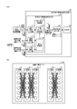
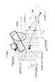
- FIG. 17 is a schematic diagram showing an aspect of reflected light based on a flare stack in a gas facility.
- the equipment around the flare stack is illuminated by the emitted infrared rays and observed as a high-intensity reflection component.
- the illuminance of the high-luminance reflection component also changes from moment to moment.
- the present disclosure has been made in view of the above problems, and is a reflection component suppression image generator and a reflection component suppression inference that reduce the influence of changes in the amount of infrared rays due to a high-intensity light source in gas equipment from the output image of the gas visualization image pickup device. It is an object of the present invention to provide a model generator, a reflection component suppression image generation method, and a program.
- the reflection component suppression image generator is an inspection image in which a region where gas exists in space is visualized and a gas distribution image including an image portion irradiated with light is received as an input.
- An input unit, a first image including an image portion irradiated with light on an object, and an image portion not irradiated with light on the object are included, and elements other than the image portion are equivalent to the first image.
- a high-brightness light source in a gas facility is obtained from the output image of the gas visualization image pickup device. It is possible to reduce the influence of the change in the amount of infrared rays due to the above, and it is possible to contribute to the improvement of the detection quality in the gas leakage detection.
- (A) is a functional block diagram of the control unit 21, and
- (b) is a schematic diagram showing an outline of the logical configuration of the machine learning model. It is a schematic diagram for demonstrating the feature of the image component of the reflected light based on a flare stack in a gas distribution image. It is a functional block diagram of the data generation apparatus 30 for machine learning. It is a functional block diagram in the control part of the machine learning data generation apparatus 30.
- (A) and (b) are schematic diagrams showing the data structures of the structure three-dimensional data and the optical reflection three-dimensional image data, respectively. It is a schematic diagram for demonstrating the outline of the optical reflection image calculation method in 2D single viewpoint optical reflection image conversion processing. It is a flowchart which shows the outline of the 2D optical reflection image generation processing as a teacher image in the machine learning data generation apparatus 30. It is a flowchart which shows the outline of the 2D single-viewpoint reflection component image conversion processing. It is a flowchart which shows the operation of the reflection component suppression image generation apparatus 20 in a learning phase. It is a flowchart which shows the operation of the reflection component suppression image generation apparatus 20 in the operation phase.
- FIG. It is a process diagram which shows the outline of the imaging process of a teacher's image. It is a functional block diagram in the control part of the machine learning data generation apparatus 30A which concerns on Embodiment 2.
- FIG. It is a flowchart which shows the outline of the reflection component enhancement process in the machine learning data generation apparatus 30A. It is a schematic diagram which shows the mode of the reflected light based on the flare stack in a gas facility.
- Embodiment 1 >> ⁇ Configuration of reflection component suppression image generation system 1>
- a reflection component suppression image generation that suppresses an image component of reflected light in an inspection image including a background image portion irradiated with high-intensity light such as a flare stack is performed. It is realized as system 1.
- the reflection component suppression image generation system 1 according to the embodiment will be described in detail with reference to the drawings.
- FIG. 1 is a schematic configuration diagram of a reflection component suppression image generation system 1 according to an embodiment.
- the reflection component suppression image generation system 1 includes a plurality of gas visualization image pickup devices 10 connected to a communication network N, a reflection component suppression image generation device 20, a machine learning data generation device 30, and a storage means. It is composed of 40.
- the communication network N is, for example, the Internet, and is connected so that a gas visualization image pickup device 10, a reflection component suppression image generation device 20, a plurality of machine learning data generation devices 30, and a storage means 40 can exchange information with each other. ing.
- the gas visualization image pickup device 10 is a device or system that images a monitored object using infrared rays and provides an infrared image in which the gas is visualized to the reflection component suppression image generation device 20.
- the gas visualization image pickup device 10 includes an imaging means (not shown) including an infrared camera that detects and captures infrared rays, and an interface circuit (not shown) that outputs to the communication network N.
- Images taken with an infrared camera are generally used for detecting hydrocarbon gases.
- an image sensor having a sensitivity wavelength band at least a part of infrared light wavelengths of 3 ⁇ m to 5 ⁇ m, more preferably, for example, detecting and imaging infrared light having a wavelength of 3.2 to 3.4 ⁇ m. It is an infrared camera and can detect hydrocarbon-based gases such as methane, ethane, ethylene, and propylene.
- the gas visualization image pickup device 10 is installed so that the monitoring target 300 is included in the field of view range 310 of the infrared camera.
- the obtained inspection image is, for example, a video signal for transmitting an image of 30 frames per second.
- the gas visualization image pickup device 10 converts the captured image into a predetermined video signal.
- the infrared image signal acquired from the infrared camera is restored into an image and processed as a moving image composed of a plurality of frames.
- the image is an infrared photograph of the monitored object, and has the intensity of infrared rays as a pixel value.
- the number of pixels of the gas distribution image is 224 ⁇ 224 pixels, and the number of frames is 16.
- the gas visualization imager detects the presence of gas by capturing changes in the amount of electromagnetic waves radiated from a background object with an absolute temperature of 0 (K) or higher.
- the change in the amount of electromagnetic waves is mainly caused by the absorption of electromagnetic waves in the infrared region by the gas or the generation of blackbody radiation from the gas itself.
- the gas leak can be captured as an image by photographing the monitored space, so that the gas can be captured earlier than the conventional detection probe type that can only monitor the grid-like location. Leakage can be detected and the location of gas can be accurately detected.
- the visualized inspection image is temporarily stored in a memory or the like, and is transferred to and stored in the storage means 40 via the communication network N based on the operation input.
- the gas visualization image pickup device 10 is not limited to this, and may be any image pickup device capable of detecting the gas to be monitored.
- the monitoring target is a gas that can be detected by visible light such as white smoked water vapor. It may be a general visible light camera.
- the gas refers to a gas leaked from a closed space such as a pipe or a tank, and is not intentionally diffused into the atmosphere.
- the storage means 40 is a storage device for storing inspection images transmitted from the gas visualization image pickup device 10, and is a volatile memory such as a DRAM (Dynamic Random Access Memory) and a non-volatile memory such as a hard disk. It is configured to include sexual memory.
- a volatile memory such as a DRAM (Dynamic Random Access Memory) and a non-volatile memory such as a hard disk. It is configured to include sexual memory.
- the reflection component suppression image generation device 20 acquires an inspection image of the monitored object from the gas visualization image pickup device 10, and the image component of the reflected light in the background image portion where the imaged object is irradiated with high-intensity light such as a flare stack. It is a device that provides a reflected component suppressed image in which the image component of the reflected light is suppressed to the user through the display unit 24.
- the reflection component suppression image generation device 20 is realized as, for example, a computer including a general CPU (Central Processing Unit), a RAM (Random Access Memory), and a program executed by these. As will be described later, the reflection component suppression image generation device 20 may further include a GPU (Graphics Processing Unit) and a RAM as arithmetic units.
- FIG. 3 is a diagram showing the configuration of the reflection component suppression image generation device 20.
- the reflection component suppression image generation device 20 includes a control unit (CPU) 21, a communication unit 22, a storage unit 23, a display unit 24, and an operation input unit 25, and a gas leak detection program is provided by the control unit 21. It is realized as a computer that executes.
- the communication unit 22 transmits / receives information to / from the reflection component suppression image generation device 20 and the storage means 40.
- the display unit 24 is, for example, a liquid crystal panel or the like, and displays a display screen generated by the CPU 21.
- the storage unit 23 stores the program 231 and the like necessary for the reflection component suppression image generation device 20 to operate, and also has a function as a temporary storage area for temporarily storing the calculation result of the CPU 21.
- the storage unit 23 includes, for example, a volatile memory such as a DRAM and a non-volatile memory such as a hard disk.
- the control unit 21 realizes each function of the reflection component suppression image generation device 20 by executing the gas leak detection program 231 in the storage unit 23.
- FIG. 4A is a functional block diagram of the control unit 21.
- the reflection component suppression image generation device 20 includes an inspection image input unit 211, a training image input unit 212, a correct image input unit 213, a machine learning unit 2141, a learning model holding unit 2142, and a determination result.
- the output unit 215 is provided.
- the machine learning unit 2141 and the learning model holding unit 2142 form a reflection component suppressing unit 214.
- the inspection image input unit 211, the training image input unit 212, the correct answer image input unit 213, the reflection component suppression unit 214, and the determination result output unit 215 constitute the reflection component suppression image generation unit 210.
- the inspection image input unit 211 is a circuit for acquiring an inspection image from the gas visualization image pickup device 10.
- a device such as an image capture board that captures image data into a processing device such as a computer can be used.
- the inspection image is an infrared image captured by an infrared camera, and is an image showing a gas distribution that visualizes a gas leak portion to be inspected.
- the inspection image may be a moving image including time series data of a plurality of frames.
- the inspection image may include a background image portion generated by the light emitted to the image pickup target such as a gas facility. be.
- Gain adjustment, offset adjustment, image inversion processing, and the like may be performed as necessary in the post-stage processing.
- the training image input unit 212 is an image having the same format as the inspection image generated by the gas visualization image pickup device 10, and is an image portion in which a target such as a gas facility is irradiated with high-intensity light generated by a flare stack or the like. It is a circuit that accepts an input of a reflection component-containing image (hereinafter, may be referred to as a "first image") including an image component of high-intensity reflected light.
- the first image may be a moving image including time series data of a plurality of frames.
- the first image is output to the machine learning unit 2141 as a training image for machine learning.
- the training image input unit 212 performs processing such as cutting out and scaling so that the acquired image has the same format. You may. Further, for example, when the acquired image is three-dimensional voxel data, it may be converted into a two-dimensional image of a viewpoint from one point.
- the correct image input unit 213 is an image having the same format as the inspection image generated by the gas visualization image pickup device 10, and is an image portion in which a target such as a gas facility is irradiated with high-intensity light generated by a flare stack or the like. It is a circuit that accepts an input of a reflection component-free image (hereinafter, may be referred to as a "second image") that does not contain an image component of high-intensity reflected light.
- the second image may also be a moving image including time series data of a plurality of frames.
- the second image is an image captured or generated under the same conditions for elements other than the image component of the reflected light for the same object as the first image forming a pair as a pair.
- the second image is output to the machine learning unit 2141 as a correct image for machine learning.
- the machine learning unit 2141 executes machine learning based on the combination of the first image received by the training image input unit 212 and the second image received by the correct answer image input unit 213, and generates a machine learning model. It is a circuit.
- machine learning for example, a convolutional neural network (CNN) can be used, and known software such as PyTorch can be used.
- CNN convolutional neural network
- FIG. 4B is a functional block diagram of the machine learning unit 2141 in the control unit 21.
- the machine learning model includes an input layer 51, an intermediate layer 52-1, an intermediate layer 52-2, ..., An intermediate layer 52-n, and an output layer 53, and the interlayer filter is optimized by learning.
- the input layer 51 accepts a 224 ⁇ 224 ⁇ 16 three-dimensional tensor in which the pixel value of the image to be processed is input.
- the intermediate layer 52-1 is, for example, a convolution layer, and receives a 224 ⁇ 224 ⁇ 16 three-dimensional tensor generated by a convolution operation from the data of the input layer 51.
- the intermediate layer 52-2 is, for example, a pooling layer, and accepts a three-dimensional tensor obtained by resizing the data of the intermediate layer 52-1.
- the intermediate layer 52-n is, for example, a fully connected layer, and the data of the intermediate layer 52- (n-1) is converted into a two-dimensional vector showing coordinate values.
- the configuration of the intermediate layer is an example, and the number n of the intermediate layers is about 3 to 5, but the number n is not limited to this. Further, in FIG. 4B, the number of neurons in each layer is drawn as the same, but each layer may have an arbitrary number of neurons.
- the machine learning unit 2141 receives a moving image as a processing target image, performs learning with the gas leakage position as the correct answer, generates a machine learning model, and outputs it to the learning model holding unit 2142.
- the machine learning unit 2141 includes a machine learning model including an input layer 51, an intermediate layer 52, and an output layer 53, and a model learning processing program.
- Each of the intermediate layers 52-1, 52-2 ... 52-n is composed of a plurality of processing layers such as a convolution layer and a MaxPooling layer, and the input layer 51 does not contain a reflection component of the same scene as a correct image.
- An image and an image containing a reflection component to which a reflection component is added are input via the training image input unit 212 and the correct answer image input unit 213, respectively.
- the output layer 53 is a part where the result during learning is output for each learning step.
- the machine through the procedure of modifying the parameters (weight, gain, etc. of each node) of the intermediate layers 52-1, 52-2 ... 52-n while comparing the output result with the correct image by the model learning processing program.
- a learning model is formed.
- Machine learning is performed by inputting a large number of learning data, which is a set of a correct image that is a high-intensity reflection component-free image and a high-intensity reflection component-containing image to which a high-intensity reflection component is added, into the machine learning unit 2141.
- the learning accuracy of the model can be improved.
- the machine learning unit 2141 may be realized by the GPU and software when the reflection component suppression image generation device 20 includes a GPU and a RAM as arithmetic units.
- the location where the reflection component is generated is estimated by capturing the changed portion of the synchronized high-luminance signal appearing in the input image, and the reflection component suppression image is generated. be able to.
- a learning model that generates an image in which the high-intensity reflection component is suppressed is estimated based on the following characteristics of the high-intensity reflected light image component.
- FIG. 5 is a schematic diagram for explaining the characteristics of the image component of the high-intensity reflected light based on the flare stack in the gas distribution image.
- the image component of the high-intensity reflected light based on the flare stack is an image taken by the gas visualization image pickup apparatus 10 when the light based on the flare stack is reflected on the structure.
- This high-intensity reflected light image component has the following features. Specifically, (1) the position of the high-intensity reflected light image component in the gas distribution image is fixed. (2) The time change is synchronized between a plurality of high-intensity reflected light image components in the gas distribution image.
- the machine learning model has, for example, the absolute value of the luminance, the outer peripheral shape, the luminance distribution, the area, the position, and the position of the image component of the high luminance reflected light in the image portion where the light in the gas distribution image is applied to the object.
- a machine learning estimation model is constructed and high brightness reflection is performed. It is formed to predict the generation and magnitude of image components of light.
- the learning model holding unit 2142 holds the machine learning model generated by the machine learning unit 2141, and targets the high-brightness light generated by the flare stack or the like acquired by the inspection image input unit 211 using the machine learning model. It is a circuit that generates and outputs a reflection component suppression image in which the image component of high-intensity reflected light is suppressed in a gas distribution image including an image portion irradiated with.
- the reflection component suppression unit 214 has the same high brightness as the initial inspection image acquired from the inspection image input unit 211. Based on the machine learning model generated by the machine learning unit 2141 based on the correspondence with the reflection component, the high-intensity reflection component reduction in the inspection image is reduced with respect to the input initial inspection image. An image is formed, and the error between the formed high-intensity reflection component-reduced image and the correct image is calculated. Then, in order to reduce the error, the update amount of the parameters (weight, gain, etc. of each node) of the intermediate layers 52-1, 52-2 ...
- the parameter update amount can be calculated using, for example, a known algorithm such as a gradient method, a nearest neighbor method, or an error back propagation method. As a result, an image with a reduced reflection component is generated and output based on the inspection image consisting of the input gas visualization image.
- the learning model holding unit 2142 produces an image in which the high-intensity reflection component of the inspection image is reduced based on the inspection image consisting of the input gas visualization image based on the machine learning model generated by the machine learning unit 2141. Generate and output.
- the determination result output unit 215 is a circuit that generates a display image for displaying the second image output by the learning model holding unit 2142 on the display unit 24.
- FIG. 6 is a diagram showing the configuration of the machine learning data generation device 30.
- the machine learning data generation device 30 includes a control unit (CPU) 31, a communication unit 32, a storage unit 33, a display unit 34, and an operation input unit 35, and the control unit 31 provides machine learning data. It is realized as a computer that executes the generator.
- the control unit 31 realizes the function of the machine learning data generation device 30 by executing the machine learning data generation program 331 in the storage unit 33.
- FIG. 7 is a functional block diagram of the control unit of the machine learning data generation device 30.
- the condition parameters required for the processing input in each functional block in FIG. 7A are as shown in the table below.
- the machine learning data generation device 30 has a three-dimensional structure modeling unit 311 and each unit temperature setting unit 312, a three-dimensional optical illumination analysis simulation execution unit 313, and a two-dimensional single-viewpoint reflection component image.
- a conversion processing unit 314 is provided.
- the 3D structure modeling unit 311 designs a 3D structure unit model based on the operation input of the condition parameter CP1 from the operator to the operation input unit 35, and lays out the structure in the 3D space. Modeling is performed and the structure 3D data DTstr is output to the subsequent stage.
- Conditional parameter CP1 includes, for example, parameters related to structural conditions such as structure position, structural surface optical characteristics such as reflectance and emissivity.
- the three-dimensional structure data DTstr is shape data representing, for example, the three-dimensional shape of a pipe or other plant facility.
- Commercially available 3D CAD (Computer-Aided Design) software can be used for 3D structure modeling.
- FIG. 8A is a schematic diagram showing the data structure of the three-dimensional structure data DTstr.
- the X direction, the Y direction, and the Z direction in each figure are the width direction, the depth direction, and the height direction, respectively.
- the structure three-dimensional data DTstr is three-dimensional boxel data representing a three-dimensional space, and is derived from the structure identification information Std arranged at the coordinates in the X direction, the Y direction, and the Z direction. It is composed. Since the structure identification information Std is expressed as three-dimensional shape data, it may be recorded as a binary image with 0 and 1 such as "with structure" and "without structure". Alternatively, the structure three-dimensional data DTstr may be assigned a value indicating the classification of the structure surface for each pixel and recorded as a multi-valued image such as 0, 1, 2, 3, ....
- the surface classification Std is a classification number classified based on, for example, the optical characteristics of the surface of the structure.
- the unpainted pipe may be set to 1
- the painted pipe may be set to 2
- the concrete may be set to 3.
- the position of the structure and the optical characteristic conditions of the surface of the structure are set as shown in the structural conditions.
- the temperature setting unit 312 of each unit acquires the structure 3D data DTstr as an input, and further, the structure with respect to the structure 3D data DTstr based on the operation input of the condition parameter CP2 from the operator to the operation input unit 35. Temperature conditions are assigned to each part of the object surface, and the structure radiation 3D data DTemt on the surface of the structure laid out in the 3D space is output to the subsequent stage. Examples of the condition parameter CP2 include parameters related to temperature conditions such as the structure temperature and the ambient temperature of the structure. The temperature of the structure itself and the temperature around the structure are set, and for example, changes in the amount of infrared rays depending on the season can be reflected in learning.
- the 3D optical illumination analysis simulation execution unit 313 acquires the structure radiation 3D data DTemt as an input, and further, based on the operation input from the operator to the operation input unit 35 of the condition parameter CP3, performs an optical illumination analysis simulation. Acquire the required condition parameter CP3.
- the condition parameter CP3 is, for example, on / off of a high-intensity illumination light source such as a flare stack, quantity, position, emission intensity, time change thereof, and time of background illumination intensity such as sunshine conditions, as shown in Table 1. It is a parameter that determines the setting conditions required for optical lighting analysis simulation, which are mainly related to lighting conditions, such as changes.
- Background lighting is lighting for reproducing illuminance changes due to weather, and its intensity is sufficiently lower than that of high-intensity lighting, and changes slowly over time.
- High-luminance lighting is lighting that generates a reflective component. In addition to the time change of intensity, set the position and number. By generating an image by changing many kinds of these conditional parameters, it is possible to generate a large number of training data.
- the 3D optical illumination analysis simulation is performed, and the 3D optical reflection image data DTrf is generated and output to the subsequent stage.
- the three-dimensional optical reflection image data DTrf is data including at least three-dimensional optical reflection characteristic distribution. The calculation is performed using commercially available optical illumination analysis simulation software, and for example, ANSYS SPEOS may be used.
- FIG. 8B is a schematic diagram showing the data structure of the three-dimensional optical reflection image data DTrf.
- the three-dimensional optical reflection image data DTrf is three-dimensional boxel data representing a three-dimensional space, and the optical reflection surface of the boxel arranged at the coordinates in the X direction, the Y direction, and the Z direction. It may be composed of a normal vector or optical reflection brightness data Lu (W / m 2).
- the optical reflection luminance data Lu of each voxel may have an aspect in which the absolute value changes based on the viewpoint position SP (X, Y, Z) described later.
- the three-dimensional optical reflection image data DTrf may be a moving image including a plurality of three-dimensional voxel time-series data in time series.
- the two-dimensional single-viewpoint reflection component image conversion processing unit 314 inputs and acquires three-dimensional optical reflection image data DTrf, and further, based on the operation input of the condition parameter CP4 from the operator to the operation input unit 35, two-dimensional. Acquire the condition parameter CP4 required for the conversion process to the single-viewpoint image.
- the condition parameter CP4 is a parameter related to the imaging conditions of the gas visualization image pickup device, such as the angle of view of the image pickup device, the line-of-sight direction, the distance, and the image resolution, as shown in Table 1, for example.
- the two-dimensional single-viewpoint reflection component image conversion processing unit 314 converts the three-dimensional optical reflection image data DTrf into the two-dimensional optical reflection image data DTrf2 observed from a predetermined viewpoint position.
- a two-dimensional image captured by the image pickup device is generated based on the structure three-dimensional data output by the three-dimensional structure model design and the image pickup conditions.
- the two-dimensional optical reflection image data DTrf2 may be a moving image including time-series data of a plurality of frames.
- the high-intensity reflection component-containing image data DTrfon based on the three-dimensional optical illumination analysis simulation under the condition that the high-intensity illumination light source is turned on (hereinafter, "reflection component-containing image”).
- reflection component-containing image based on the three-dimensional optical illumination analysis simulation under the condition that the high-intensity illumination light source is turned on
- reflection component-free image data DTrfoff high-intensity reflection component-free image data DTrfoff based on three-dimensional optical illumination analysis simulation under the condition that the high-intensity illumination light source is off (hereinafter, "May be referred to as” reflection component-free image data DTrfoff ”) and is generated as a pair.
- Two-dimensional optical reflection image data DTrf2 generated as a pair that is, a set of reflection component-containing image data DTrfon and reflection component-free image data DTrfoff are output to the reflection component suppression image generation device 20 as teacher data for machine learning. Will be done.
- the two-dimensional optical reflection image data DTrf2 is an image corresponding to an inspection image acquired by the gas visualization image pickup apparatus 10, and is an image showing how the object can be seen from a viewpoint. Further, by considering the information of the three-dimensional structure data DTstr, it is possible to generate the two-dimensional optical reflection image data DTrf2 that is blocked by the structure and does not reflect the target portion that cannot be observed from the viewpoint.
- FIG. 9 is a schematic diagram for explaining an outline of a calculation method of two-dimensional optical reflection image data DTrf2 in a two-dimensional single-viewpoint reflection component image conversion process.
- the two-dimensional single-viewpoint reflection component image conversion processing unit 314 determines the value when the optical reflection image indicated by the three-dimensional optical reflection image data DTrf is observed in the line-of-sight direction from a preset viewpoint position (X, Y, Z).
- a plurality of values of the obtained optical reflection images are generated by changing the angles ⁇ and ⁇ in the line-of-sight direction, and the values of the obtained optical reflection images are arranged two-dimensionally to generate the two-dimensional optical reflection image data DTrf2.
- an arbitrary viewpoint position SP (X, Y, Z) is set in the three-dimensional space, and the three-dimensional optical reflection image data DTrf is set from the viewpoint position SP (X, Y, Z).
- the virtual image plane VF is set at a position separated by a predetermined distance in the direction of the three-dimensional structure indicated by. At this time, the virtual image plane VF is set so that the center O intersects the viewpoint position SP (X, Y, Z) and the straight line passing through the center voxel of the three-dimensional optical reflection image data DTrf. Further, the image frame of the virtual image plane VF is set according to the angle of view of the gas visualization image pickup apparatus 10.
- the line-of-sight direction DA directed from the viewpoint position SP (X, Y, Z) toward the pixel A (x, y) of interest on the virtual image plane VF is the line-of-sight direction DO toward the central pixel O, that is, a gas visualization image pickup device.
- the angle ⁇ is in the X direction, the angle is ⁇ in the Y direction, and the direction is tilted with respect to the line-of-sight direction DO.
- a voxel of 3D optical reflection image data that first intersects the line of sight is detected along the line-of-sight direction DA corresponding to the pixel A (x, y) of interest.
- the voxel that first intersects the line of sight starting from the viewpoint position SP (X, Y, Z) exists in the visible region when viewed from the viewpoint position SP (X, Y, Z). Therefore, among the optical reflection brightness data Lu in the voxel, the optical reflection brightness data Lu emitted in the line-of-sight direction DA is calculated as the value of the two-dimensional optical reflection image data DTrf2 relating to the pixel A (x, y) of interest.
- the viewpoint position SP (X, For voxels existing behind the structure when viewed from Y, Z)
- the two-dimensional optical reflection image data DTrf2 is not calculated for the pixel A (x, y) of interest.
- the two-dimensional optical reflection image data DTrf2 is calculated by repeating the calculation of the value of the two-dimensional optical reflection image data as A (x, y).
- the storage unit 33 stores the program 331 and the like necessary for the machine learning data generation device 30 to operate, and also serves as a temporary storage area for temporarily storing the calculation result of the control unit 31. Has the function of.
- the storage unit 33 includes a volatile memory such as a DRAM and a non-volatile memory such as a hard disk.
- the communication unit 32 transmits / receives information to / from the machine learning data generation device 30 and the storage means 40.
- the display unit 34 is, for example, a liquid crystal panel or the like, and displays a display screen generated by the CPU 31.
- FIG. 10 is a flowchart showing an outline of a two-dimensional optical reflection image generation process as a teacher image in the machine learning data generation device 30.
- the 3D structure modeling unit 311 designs the 3D structure model (step S101), and outputs the 3D structure data DTstr to the subsequent stage.
- step S102 based on the operation input of the condition parameter CP2 regarding the temperature condition, the temperature of the structure and the surface of the structure is set in the temperature setting unit 312 of each part (step S102), and the temperature condition is assigned to each part of the surface of the structure.
- the structure radiation 3D data DTemt on the surface of the structure laid out in the 3D space is output.
- the high-intensity lighting by the flare stack / the background lighting by the weather is set (step S103), and the viewpoint position and the distance are set.
- the 3D optical illumination analysis simulation execution unit 313 uses known optical illumination analysis simulation software to set the 3D reflected light and brightness on the surface of the structure to high-intensity illumination on / off conditions.
- Step S104 a pair of three-dimensional optical reflection image data DTrf corresponding to high-intensity illumination on / off is generated and output to the subsequent stage.
- the two-dimensional single-viewpoint reflection component image conversion processing unit 314 performs the two-dimensional single-viewpoint image conversion processing to generate a reflection component-containing / non-reflection component-containing image (step S105). ),
- the pair of reflection component-containing image data DTrfon corresponding to high-intensity illumination on / off and the reflection component-free image data DTrfoff are output as teacher data for machine learning.
- FIG. 11 is a flowchart showing an outline of the two-dimensional single-viewpoint reflection component image conversion process. The processing is executed by the two-dimensional single-viewpoint reflection component image conversion processing unit 314 whose function is configured by the control unit 31.
- the two-dimensional single-viewpoint reflection component image conversion processing unit 314 acquires the structure three-dimensional data DTstr (step S401) and acquires the three-dimensional optical reflection image data DTrf (flare / high-intensity illumination on condition). Further, the three-dimensional optical reflection image data DTrf is acquired (non-flare / high-intensity illumination off condition) (step S402).
- the condition parameter CP4 for example, the input of information regarding the angle of view of the image pickup device, the line-of-sight direction, the distance, and the image resolution is accepted (step S403). Further, based on the operation input, the viewpoint position SP (X, Y, Z) corresponding to the position of the image pickup portion of the gas visualization image pickup apparatus 10 is set in the three-dimensional space (step S404).
- a virtual image plane VF separated from the viewpoint position SP (X, Y, Z) in the direction of the three-dimensional structure by a predetermined distance is set, and as described above, the position of the image frame of the virtual image plane VF is gas-visualized and imaged. It is calculated according to the angle of view of the device 10 (step S405).
- step S406 the coordinates of the pixel of interest A (x, y) are set to the initial value (step S406), and the pixel of interest A (x, y) on the virtual image plane VF is changed from the viewpoint position SP (X, Y, Z).
- the position LV on the line of sight is set to the initial value (step S407).
- step 408 when the structure 3D data DTstr that intersects the line of sight is “with structure”, the brightness at the intersection voxel with the 3D optical reflection image data DTrf (high brightness illumination on condition) at the time of flare stack.
- the value data (Lu) is output as an image with a reflection component (step S409), and the brightness value data (Lu) at the intersection voxel with the three-dimensional optical reflection image data DTrf (high brightness illumination off condition) at the time of non-flare stack is output. It is output as an image with a reflection component (step S410), the position of the pixel A (x, y) of interest is gradually moved (step S411), and the process returns to step S407.
- step S412 it is determined whether or not the calculation is completed for the total length of the line of sight corresponding to the range where the line of sight and the voxel intersect (step S412), and if it is not completed, the line of sight is not completed.
- the position LV on the line is incremented by the unit length (step S413), and the process returns to step S408.
- step S414 it is determined whether or not the calculation is completed for all the pixels on the virtual image surface VF (step S414), and if it is not completed, the pixel A (x, y) of interest is determined.
- the standard value set when there is no structure is determined as the luminance value data in the pixel A of interest.
- the standard value is, for example, luminance value data corresponding to the ground or the sky in a real space.
- a standard value can be obtained by appropriately setting the conditions indicated by the condition parameters CP1 and CP2.
- the two-dimensional optical reflection image data DTrf2 at the time of flare stack and at the time of non-flare stack is generated for all the pixels on the virtual image plane VF, respectively. That is, a set of reflection component-containing image data DTrfon and a reflection component-free image data DTrfoff regarding the virtual image surface VF are generated.
- step S416 it is determined whether or not the generation of the two-dimensional optical reflection image data DTrf2 is completed for all the viewpoint positions SP (X, Y, Z) to be calculated (step S416), and if not, it is determined.
- step S404 the two-dimensional optical reflection image data DTrf2 is generated for the new viewpoint position SP (X, Y, Z) input by the operation, and if it is completed, the process is terminated.
- 3D optical illumination analysis simulation is performed while changing various setting conditions, and from the results, 3D optical reflection image data is acquired under the high-intensity illumination off condition and the high-intensity illumination on condition, respectively. Then, by converting it into two-dimensional optical reflection image data by a two-dimensional single-viewpoint processing, a large amount of training data set consisting of a pair of reflection component-free image data and reflection component-containing image data under the same conditions can be efficiently combined. Can be generated in.
- machine learning In the inspection of gas equipment, it is considered effective to identify the position of the gas leak source hidden behind the equipment such as piping that is complicatedly complicated from the inspection image by using machine learning.
- machine learning generally requires 10,000 units of correct answer data, and in order to realize it, it is necessary to efficiently acquire a large amount of learning data for teachers regarding gas equipment.
- FIG. 12 is a flowchart showing the operation of the reflection component suppression image generation device 20 in the learning phase.
- the machine learning data generation device 30 creates a combination of a pair of reflection component-containing image data DTrfon corresponding to high-intensity lighting on / off and reflection component-free image data DTrfoff under equivalent conditions (step S10).
- Each set of teacher images consists of multiple frames of time-series data.
- a pair of reflection component-containing image data corresponding to high-intensity illumination on / off As reflection component-free image data DTrfoff under the same conditions as DTrfon, three-dimensional optical reflection image data is observed from a predetermined viewpoint position in two-dimensional optics. Reflected image data can be used.
- the three-dimensional optical reflection image data may be based on a three-dimensional optical illumination analysis simulation. For example, 3D CAD (Computer-Aided Design) software on the market is used to model the 3D concept of gas equipment, and 3D optical illumination analysis simulation software on the market is used in consideration of the structure model.
- An optical illumination analysis simulation may be performed, and the three-dimensional optical reflection image data obtained as a simulation result may be converted into a two-dimensional image observed from a predetermined viewpoint position and generated.
- step S11 a combination of a pair of reflection component-containing image data DTrfon corresponding to high-intensity illumination on / off and reflection component-free image data DTrfoff under equivalent conditions is used, and the reflection component-free image is used as the correct image, and the machine learning unit 2141 is used.
- the reflection component-containing image data DTrfon is input to the training image input unit 212, and the corresponding reflection component-free image data DTrfoff is input to the correct image input unit 213.
- image data that has undergone processing such as gain adjustment may be input.
- step S12 input data to the convolutional neural network and execute machine learning (step S12).
- the parameters are optimized by trial and error by deep learning, and a machine-learned model is formed.
- the formed machine-learned model is held in the learning model holding unit 2142.
- a machine-learned model that outputs an image in which the high-intensity reflection component is suppressed is formed based on the characteristics of the image containing the high-intensity reflected light.
- FIG. 13 is a flowchart showing the operation of the reflection component suppression image generation device 20 in the operation phase.
- the inspection image acquired by the gas visualization image pickup apparatus 10 is input from the inspection image input unit 211 to the trained model holding unit 2142 (step S30).
- the inspection image is image data in the same format as the teacher image, and consists of time-series data of a plurality of frames.
- the inspection image is an infrared image captured by the infrared camera of the gas visualization image pickup device 10, and is a moving image showing a gas distribution that visualizes a gas leak portion to be inspected. Offset component subtraction and gain adjustment may be performed on the inspection image.
- the inspection image When high-intensity light generated by a flare stack or the like is imaged, the inspection image includes a background image portion in which the light is applied to an imaged object such as a gas facility as a high-intensity reflection component. A part of each frame of the captured image may be cut out so as to include all the pixels in which gas is detected, and an inspection image may be generated as a frame of the gas distribution image.
- a reflection component suppression image is generated using the trained model (step S31).
- a reflection component suppression image in which the high-luminance reflection component contained in the inspection image is reduced is generated by using the inspection image as an input.
- the high-intensity reflection component suppression image is displayed on the display unit (step S32).
- a reflection component suppression image is generated.
- Patent Document 3 discloses a technique for inputting at least two types of captured images having different exposure times and removing flicker components. ing. This is a technique for removing flicker generated by an illumination light source such as a fluorescent lamp, but the flicker to be removed is periodic, and it is difficult to remove a random luminance change such as a flare stack.
- the reflection component suppression image generation device 20 according to the actual embodiment, a learning model obtained by machine learning using an image illuminated by a high-intensity light source and an image not illuminated as a learning set. Since the image with the reflection component removed by the high-intensity light source illumination is generated from the gas leak image using the above, the influence of the change in the amount of infrared rays due to the high-intensity light source can be eliminated and the detection rate of gas leakage is improved. can.
- the reflection component suppression image generator it is possible to reduce the influence of the change in the amount of infrared rays due to the high-intensity light source in the gas equipment from the output image of the gas visualization image pickup device, and gas leakage. It can contribute to the improvement of detection quality in detection.
- FIG. 14 is a process diagram showing an outline of the image capturing process for teacher images.
- step S10A place the structure in a studio or the like (step S10A).
- the structure arrangement setting as shown in the structural conditions in Table 1, the position of the structure to be photographed and the optical characteristic conditions of the structure surface are set.
- a simulated plant equipment that imitates the plant equipment and a structure such as a model structure that can be photographed under illumination by a high-intensity illumination light source are used.
- Surface processing such as painting is applied to make the optical characteristics of the surface of the structure equal to the actual plant equipment.
- step S11A the temperature of the structure and the temperature of the surface of the structure are set using a heating device.
- the temperature of the structure itself and the temperature around the structure are set as shown in the temperature conditions of Table 1 in order to reflect the change in the amount of infrared rays depending on the season in the learning.
- a high-intensity illumination light source is used to set high-intensity illumination by flare stack, and natural light or normal illumination is used to set background illumination by weather (step S12A).
- the high-intensity illumination is the illumination that generates the reflection component to be removed in this case.
- the background lighting is a lighting for reproducing the illuminance change due to the weather, and its intensity is sufficiently lower than that of the high-luminance lighting, and it is assumed that the lighting changes slowly with time.
- the image pickup conditions such as the image pickup position, the distance, the angle of view, and the resolution are set (step S13A), and the moving image is obtained by the gas visualization image pickup device in the condition with / without high-brightness illumination. Take a picture (step S14A).
- the image pickup conditions such as the angle of view and the viewpoint of the image pickup apparatus are set.
- an image containing no reflective component is acquired by taking an image with the high-intensity lighting off, and then an image containing a reflective component is acquired by taking an image with the high-intensity illumination turned on. And various learning data can be acquired.
- FIG. 15 is a functional block diagram of the control unit of the machine learning data generation device 30A.
- the condition parameters required for the processing input in each functional block in FIG. 15 are as shown in the above table.
- the same components as those of the machine learning data generation device 30 are assigned the same numbers, and the description thereof will be omitted.
- the machine learning data generation device 30A is different from the machine learning data generation device 30 in that a reflection component enhancement processing unit 315A is newly provided after the two-dimensional single-viewpoint reflection component image conversion processing unit 314.
- the reflection component enhancement process is an enhancement process for a predetermined frequency for a time-series image so that the behavior of an image component irradiated to a target by high-luminance light generated by a flare stack or the like can be emphasized.
- the reflection component enhancement processing unit 315A extracts a specific frequency component from the image data DTrfon containing a high-intensity reflection component, and performs various enhancement processing on the high-intensity reflection image component caused by a flare stack or the like. Generates reflected component-enhanced image data DTrem.
- FIG. 16 is a flowchart showing an outline of the reflection component enhancement process.
- the reflection component enhancement processing unit 315A acquires time-series data of the high-intensity reflection component-containing image data DTrfon (flare / high-intensity illumination on condition) (step S201).
- the time-series signal of the brightness of each pixel is decomposed into time-frequency components (step S202).
- a method such as Fourier transform or wavelet transform is used for time-frequency decomposition.
- the restored image is generated by restoring the time-series signal of the brightness of each pixel (step S204).
- a method such as an inverse Fourier transform or an inverse wavelet transform corresponding to the method used at the time-frequency decomposition is used.
- the machine learning data generator 30A performs various enhancement processes on the high-brightness reflected image components caused by flare stacks and the like by changing the gain adjustment for each frequency component, thereby performing various reflection components.
- the enhanced image data DTrem can be generated.
- the generated reflection component-enhanced image data DTrem and the reflection component-free image data DTrfoff can be used as a set as teacher data for machine learning used in the reflection component suppression image generation device 20, and a large amount of training data can be efficiently set. It can be generated as a target and can contribute to the improvement of learning accuracy.
- a gas plant is illustrated as a gas facility as an example of an inspection image.
- the present disclosure is not limited to this, and may be applied to the generation of display images in equipment, devices, laboratories, laboratories, factories, and business establishments that use gas.
- the present invention is a computer system including a microprocessor and a memory, and the memory may store the computer program, and the microprocessor may operate according to the computer program.
- a computer system having a computer program for processing in the reflection component suppression image generation system 1 of the present disclosure or a component thereof, and operating according to this program (or instructing each connected part to operate). May be good.
- the processing in the reflection component suppression image generation system 1 or its constituent elements is configured by a computer system composed of a microprocessor, a recording medium such as a ROM, a RAM, a hard disk unit, and the like. Included in the invention.
- the RAM or the hard disk unit stores a computer program that achieves the same operation as each of the above devices. When the microprocessor operates according to the computer program, each device achieves its function.
- a system LSI is a super-multifunctional LSI manufactured by integrating a plurality of components on one chip, and specifically, is a computer system including a microprocessor, ROM, RAM, and the like. .. These may be individually integrated into one chip, or may be integrated into one chip so as to include a part or all of them.
- a computer program that achieves the same operation as each of the above devices is stored in the RAM. When the microprocessor operates according to the computer program, the system LSI achieves its function.
- the present invention may also be a case where the processing in the reflection component suppression image generation system 1 or its constituent elements is stored as an LSI program, and this LSI is inserted into a computer to execute a predetermined program (gas inspection management method).
- a predetermined program gas inspection management method
- the method of making an integrated circuit is not limited to LSI, and may be realized by a dedicated circuit or a general-purpose processor.
- An FPGA Field Programmable Gate Array
- a reconfigurable processor that can reconfigure the connection and settings of the circuit cells inside the LSI may be used.
- a part or all of the functions of the reflection component suppression image generation system 1 or its components may be realized by executing a program by a processor such as a CPU. It may be a non-temporary computer-readable recording medium in which a program for performing the operation of the reflection component suppression image generation system 1 or its components is recorded. By recording a program or signal on a recording medium and transferring it, the program may be executed by another independent computer system. Needless to say, the above program can be distributed via a transmission medium such as the Internet.
- the reflection component suppression image generation system 1 or each component thereof according to the above embodiment may be configured to be realized by a programmable device such as a CPU, a GPU (Graphics Processing Unit) or a processor, and software.
- a programmable device such as a CPU, a GPU (Graphics Processing Unit) or a processor, and software.
- These components can be a single circuit component or an aggregate of a plurality of circuit components. Further, a plurality of components can be combined into one circuit component, or an aggregate of a plurality of circuit components can be formed.
- Division of functional blocks is an example, and even if multiple functional blocks are realized as one functional block, one functional block is divided into multiple, or some functions are transferred to other functional blocks. good. Further, the functions of a plurality of functional blocks having similar functions may be processed by a single hardware or software in parallel or in a time division manner.
- the order in which the above steps are executed is for exemplifying in order to specifically explain the present invention, and may be an order other than the above. Further, a part of the above steps may be executed simultaneously with other steps (parallel).
- the region where the gas exists in the space is visualized, and the gas distribution image including the image portion where the light is applied to the target is input.
- the inspection image input unit that accepts, A first image including an image portion irradiated with light on an object, and a second image equivalent to the first image with respect to elements other than the image portion including an image portion not irradiated with light on the object.
- Reflection that generates a reflection component suppression image that suppresses the image component of the reflected light in the image portion of the gas distribution image received by the inspection image input unit using a machine-learned estimation model using the combination with and as teacher data. It is characterized by including a component suppression image generation unit.
- the guessing model may be configured to be a machine-learned guessing model using the second image as a correct answer image.
- the image input to the inspection image input unit, the first image, and the second image are moving images including a plurality of frames. May be.
- the image component of the reflected light may be configured to be a time-varying component in the image portion irradiated with the light.
- the first image may be an image obtained by amplifying a specific frequency component in the time direction.
- the first image may be configured to be an image obtained by simulation.
- the light emitted to the target may be the light emitted from the light source based on the flare stack.
- the image portion of the first image irradiated with light comprises an image component of reflected light based on the flare stack.
- the image portion where the target is not irradiated with light may be configured not to include the image component of the reflected light based on the flare stack.
- the reflection component suppression inference model generation device includes an image input unit and A first image including an image portion irradiated with light on an object, and a second image equivalent to the first image with respect to elements other than the image portion including an image portion not irradiated with light on the object.
- An inference model that uses the combination with and as teacher data, executes machine learning by inputting an image including an image portion irradiated with light to the target, and outputs a reflection component suppression image in which the image component of the reflected light in the image portion is suppressed. It may be configured to include a machine learning unit for generating an image.
- the image input to the inspection image input unit, the first image, and the second image are moving images including a plurality of frames. May be.
- the image component of the reflected light may be configured to be a time-varying component of a high-luminance portion in the image portion irradiated with the light.
- the first image may be an image obtained by amplifying a specific frequency component in the time direction.
- a gas distribution image including an image portion in which a gas existing region in space is visualized and light is irradiated to the target is accepted as an input.
- the program according to the present embodiment is a program for causing a computer to perform a reflection component suppression image generation process.
- the reflection component suppression image generation process is performed.
- the gas distribution image including the image part where the existence area of the gas in the space is visualized and the object is irradiated with light is accepted as an input.
- a configuration for generating a reflection component suppression image in which the image component of reflected light in the image portion of the gas distribution image received by the inspection image input unit is suppressed. May be.
- the order in which the above method is executed is for exemplifying for concretely explaining the present invention, and may be an order other than the above. Moreover, a part of the above-mentioned method may be executed at the same time (parallel) with another method.
- the machine learning data generation device, the machine learning data generation method, and the learning data set according to the embodiment of the present disclosure can be widely applied to a system that uses a gas leak in a gas facility for inspection.
- Reflection component suppression image generation system 10 Gas visualization image pickup device 20 Reflection component suppression image generation device 21 Control unit (CPU) 210 Reflection component suppression image generation unit 211 Inspection image input unit 212 Training image input unit 213 Correct image input unit 214 Reflection component suppression unit 2141 Machine learning unit 2142 Learning model holding unit 215 Judgment result output unit 22 Communication unit 23 Storage unit 231 Program 24 Display unit 25 Operation input unit 30 Machine learning data generator 31 Control unit (CPU) 311 3D structure modeling unit 312 Each part Temperature setting unit 313 3D optical lighting analysis simulation execution unit 314 2D single-viewpoint reflection component image conversion processing unit 315 Reflection component enhancement processing unit 32 Communication unit 33 Storage unit 331 Program 34 Display unit 35 Operation input unit 40 Storage means
Landscapes
- Physics & Mathematics (AREA)
- General Physics & Mathematics (AREA)
- Engineering & Computer Science (AREA)
- Theoretical Computer Science (AREA)
- Quality & Reliability (AREA)
- Computer Vision & Pattern Recognition (AREA)
- Investigating Or Analysing Materials By Optical Means (AREA)
- Image Analysis (AREA)
Priority Applications (2)
| Application Number | Priority Date | Filing Date | Title |
|---|---|---|---|
| JP2022530079A JP7746990B2 (ja) | 2020-06-10 | 2021-05-14 | 反射成分抑制画像生成装置、反射成分抑制推論モデル生成装置、反射成分抑制画像生成方法、及びプログラム |
| US17/925,231 US20230351568A1 (en) | 2020-06-10 | 2021-05-14 | Reflection-component-reduced image generating device, reflection component reduction inference model generating device, reflection-component-reduced image generating method, and program |
Applications Claiming Priority (2)
| Application Number | Priority Date | Filing Date | Title |
|---|---|---|---|
| JP2020-100650 | 2020-06-10 | ||
| JP2020100650 | 2020-06-10 |
Publications (1)
| Publication Number | Publication Date |
|---|---|
| WO2021251062A1 true WO2021251062A1 (ja) | 2021-12-16 |
Family
ID=78847195
Family Applications (1)
| Application Number | Title | Priority Date | Filing Date |
|---|---|---|---|
| PCT/JP2021/018407 Ceased WO2021251062A1 (ja) | 2020-06-10 | 2021-05-14 | 反射成分抑制画像生成装置、反射成分抑制推論モデル生成装置、反射成分抑制画像生成方法、及びプログラム |
Country Status (3)
| Country | Link |
|---|---|
| US (1) | US20230351568A1 (https=) |
| JP (1) | JP7746990B2 (https=) |
| WO (1) | WO2021251062A1 (https=) |
Cited By (5)
| Publication number | Priority date | Publication date | Assignee | Title |
|---|---|---|---|---|
| US12518529B2 (en) | 2022-11-15 | 2026-01-06 | Cisco Technology, Inc. | Reflection detection in video analytics |
| US12524670B2 (en) | 2022-12-23 | 2026-01-13 | Cisco Technology, Inc. | Automated ground truth generation using a neuro-symbolic metamodel |
| US12536800B2 (en) | 2023-02-23 | 2026-01-27 | Cisco Technology, Inc. | Privacy preserving person reidentification |
| US12548371B2 (en) | 2023-02-09 | 2026-02-10 | Cisco Technology, Inc. | Behavioral group analytics for video |
| US12608938B2 (en) | 2022-11-14 | 2026-04-21 | Cisco Technology, Inc. | Self-supervised learning for video analytics |
Families Citing this family (2)
| Publication number | Priority date | Publication date | Assignee | Title |
|---|---|---|---|---|
| WO2023239351A1 (en) * | 2022-06-06 | 2023-12-14 | Landmark Graphics Corporation | Emissions estimations at a hydrocarbon operation location using a data-driven approach |
| US20250265694A1 (en) * | 2024-02-15 | 2025-08-21 | Kla Corporation | Deep learning model diagnostics tools using stacked images |
Citations (8)
| Publication number | Priority date | Publication date | Assignee | Title |
|---|---|---|---|---|
| US20180197048A1 (en) * | 2017-01-11 | 2018-07-12 | Ford Global Technologies, Llc | Generating Training Data for Automatic Vehicle Leak Detection |
| JP2019074777A (ja) * | 2017-10-12 | 2019-05-16 | キヤノン株式会社 | 画像処理方法、画像処理装置、および撮像装置 |
| JP2019144899A (ja) * | 2018-02-21 | 2019-08-29 | 株式会社豊田中央研究所 | 反射モデル学習装置、画像生成装置、評価装置及びプログラム |
| JP2019148940A (ja) * | 2018-02-26 | 2019-09-05 | パナソニック株式会社 | 学習処理方法、サーバ装置及び反射検知システム |
| JP2020008326A (ja) * | 2018-07-03 | 2020-01-16 | コニカミノルタ株式会社 | ガス可視化用画像処理装置、ガス可視化用画像処理方法、ガス可視化用画像処理プログラム、及び、ガス検知システム |
| CN110827207A (zh) * | 2019-09-17 | 2020-02-21 | 北京大学 | 一种基于协同分合学习机制的反射消除方法 |
| JP2020042760A (ja) * | 2018-09-07 | 2020-03-19 | パナソニック インテレクチュアル プロパティ コーポレーション オブ アメリカPanasonic Intellectual Property Corporation of America | 情報処理方法、情報処理装置、及びプログラム |
| JP2020063955A (ja) * | 2018-10-16 | 2020-04-23 | 千代田化工建設株式会社 | 流体漏洩検知システム、流体漏洩検知装置、及び学習装置 |
Family Cites Families (6)
| Publication number | Priority date | Publication date | Assignee | Title |
|---|---|---|---|---|
| US6468069B2 (en) * | 1999-10-25 | 2002-10-22 | Jerome H. Lemelson | Automatically optimized combustion control |
| CN106161875B (zh) * | 2015-03-25 | 2019-02-15 | 瑞昱半导体股份有限公司 | 图像处理装置与方法 |
| US10675955B2 (en) * | 2016-11-14 | 2020-06-09 | Google Llc | Adaptive glare removal and/or color correction |
| CN106780519B (zh) * | 2017-02-13 | 2019-05-17 | 杭州电子科技大学 | 基于快速张量鲁棒模型的视频前景提取方法 |
| KR102410834B1 (ko) * | 2017-10-27 | 2022-06-20 | 삼성전자주식회사 | 반사 영역을 제거하는 방법, 사용자의 눈을 추적하는 방법 및 그 장치 |
| CN113168670A (zh) * | 2018-11-07 | 2021-07-23 | 光谱Optix有限公司 | 使用神经网络的亮点去除 |
-
2021
- 2021-05-14 US US17/925,231 patent/US20230351568A1/en active Pending
- 2021-05-14 WO PCT/JP2021/018407 patent/WO2021251062A1/ja not_active Ceased
- 2021-05-14 JP JP2022530079A patent/JP7746990B2/ja active Active
Patent Citations (8)
| Publication number | Priority date | Publication date | Assignee | Title |
|---|---|---|---|---|
| US20180197048A1 (en) * | 2017-01-11 | 2018-07-12 | Ford Global Technologies, Llc | Generating Training Data for Automatic Vehicle Leak Detection |
| JP2019074777A (ja) * | 2017-10-12 | 2019-05-16 | キヤノン株式会社 | 画像処理方法、画像処理装置、および撮像装置 |
| JP2019144899A (ja) * | 2018-02-21 | 2019-08-29 | 株式会社豊田中央研究所 | 反射モデル学習装置、画像生成装置、評価装置及びプログラム |
| JP2019148940A (ja) * | 2018-02-26 | 2019-09-05 | パナソニック株式会社 | 学習処理方法、サーバ装置及び反射検知システム |
| JP2020008326A (ja) * | 2018-07-03 | 2020-01-16 | コニカミノルタ株式会社 | ガス可視化用画像処理装置、ガス可視化用画像処理方法、ガス可視化用画像処理プログラム、及び、ガス検知システム |
| JP2020042760A (ja) * | 2018-09-07 | 2020-03-19 | パナソニック インテレクチュアル プロパティ コーポレーション オブ アメリカPanasonic Intellectual Property Corporation of America | 情報処理方法、情報処理装置、及びプログラム |
| JP2020063955A (ja) * | 2018-10-16 | 2020-04-23 | 千代田化工建設株式会社 | 流体漏洩検知システム、流体漏洩検知装置、及び学習装置 |
| CN110827207A (zh) * | 2019-09-17 | 2020-02-21 | 北京大学 | 一种基于协同分合学习机制的反射消除方法 |
Cited By (5)
| Publication number | Priority date | Publication date | Assignee | Title |
|---|---|---|---|---|
| US12608938B2 (en) | 2022-11-14 | 2026-04-21 | Cisco Technology, Inc. | Self-supervised learning for video analytics |
| US12518529B2 (en) | 2022-11-15 | 2026-01-06 | Cisco Technology, Inc. | Reflection detection in video analytics |
| US12524670B2 (en) | 2022-12-23 | 2026-01-13 | Cisco Technology, Inc. | Automated ground truth generation using a neuro-symbolic metamodel |
| US12548371B2 (en) | 2023-02-09 | 2026-02-10 | Cisco Technology, Inc. | Behavioral group analytics for video |
| US12536800B2 (en) | 2023-02-23 | 2026-01-27 | Cisco Technology, Inc. | Privacy preserving person reidentification |
Also Published As
| Publication number | Publication date |
|---|---|
| JP7746990B2 (ja) | 2025-10-01 |
| US20230351568A1 (en) | 2023-11-02 |
| JPWO2021251062A1 (https=) | 2021-12-16 |
Similar Documents
| Publication | Publication Date | Title |
|---|---|---|
| WO2021251062A1 (ja) | 反射成分抑制画像生成装置、反射成分抑制推論モデル生成装置、反射成分抑制画像生成方法、及びプログラム | |
| JP7104098B2 (ja) | 結像、照明、および投影を用途とする効率的、動的、高コントラストなレンジング方法及び装置 | |
| CN114616587B (zh) | 基于学习的镜头眩光移除 | |
| US10628989B2 (en) | Photometric image processing | |
| JP2021502733A (ja) | カメラ内で処理を行う方法及び装置 | |
| US11526067B2 (en) | Lighting assembly for producing realistic photo images | |
| JP2007199716A (ja) | デジタル・プロジェクタとデジタル・カメラとを関連づける光輸送係数を生成する方法、および少なくとも1つのデジタル・プロジェクタと1つのデジタル・カメラとを持つプロジェクタ−カメラ・システムをキャリブレートする方法 | |
| CN103778621B (zh) | 对外来物体碎片的识别方法 | |
| CN105378573B (zh) | 信息处理装置、检查范围的计算方法 | |
| JP7772067B2 (ja) | ガス濃度特徴量推定装置、ガス濃度特徴量推定方法、プログラム、およびガス濃度特徴量推論モデル生成装置 | |
| CN115661002B (zh) | 基于gan的多时相遥感数据修复方法 | |
| CN108364292A (zh) | 一种基于多幅视角图像的光照估计方法 | |
| GB2577661A (en) | Determination of lithography effective dose uniformity | |
| US20130141420A1 (en) | Simulation of Three-Dimensional (3D) Cameras | |
| CN115330926B (zh) | 阴影估计方法、装置、电子设备和可读存储介质 | |
| JP2010281786A (ja) | 視覚検査装置の評価システム | |
| CN205749284U (zh) | 多波长同时照明的非相干叠层衍射成像系统 | |
| Li et al. | Dpcs: Path tracing-based differentiable projector-camera systems | |
| WO2021246210A1 (ja) | 機械学習用データ生成装置、機械学習用データ生成方法、プログラム及び学習用データセット | |
| US20240394964A1 (en) | Method of determining illumination pattern for three-dimensional scene and method and apparatus for modeling three-dimensional scene | |
| CN109446945A (zh) | 三维模型处理方法和装置、电子设备、计算机可读存储介质 | |
| JP2023554337A (ja) | 画像分類方法及び物体の光学検査方法 | |
| CN113592995A (zh) | 一种基于并行单像素成像的多次反射光分离方法 | |
| CN116452459B (zh) | 阴影遮罩生成方法、阴影去除方法及装置 | |
| CN119152007B (zh) | 一种雾天场景下的图像深度补全方法 |
Legal Events
| Date | Code | Title | Description |
|---|---|---|---|
| 121 | Ep: the epo has been informed by wipo that ep was designated in this application |
Ref document number: 21821018 Country of ref document: EP Kind code of ref document: A1 |
|
| ENP | Entry into the national phase |
Ref document number: 2022530079 Country of ref document: JP Kind code of ref document: A |
|
| NENP | Non-entry into the national phase |
Ref country code: DE |
|
| 122 | Ep: pct application non-entry in european phase |
Ref document number: 21821018 Country of ref document: EP Kind code of ref document: A1 |